


ENGLISH
INSTRUCTION MANUAL
* "CompactFlash(TM)" is the registered trademark of SanDisk Corporation, U.S.A.
– i –
CONTENTS
1. SETUP OF HARDWARE .................................................................................................1
1-1. Installing IPOP circuit board .........................................................................................................1
1-2. Installing the panel.........................................................................................................................1
2. HOW TO USE THE OPERATION PANEL .......................................................................2
2-1. Names and functions of each components .................................................................................2
2-2. Adjusting the contrast of the operation panel display ...............................................................4
2-3. Production control switch connecting connector ......................................................................4
2-4. Screen list .......................................................................................................................................5
2-5. How to operate the operation panel for sewing stitching patterns ...........................................7
(1) Free stitching pattern .........................................................................................................................7
(2) Constant dimension stitching pattern ..............................................................................................8
(3) Overlapped stitching pattern .............................................................................................................9
(4) Square stitching pattern ...................................................................................................................10
2-6. How to use the bobbin thread counter ......................................................................................12
2-7. Sewing counter ............................................................................................................................13
2-8. Needle up/down compensation switch ......................................................................................13
2-9. ON/OFF switch of the material edge sensor .......................................................................13
2-10. Automatic thread trimming switch .....................................................................................13
2-11. One-shot automatic stitching switch .................................................................................13
2-12. Thread trimming prohibition switch ...................................................................................14
3. INFORMATION ..............................................................................................................14
3-1. Operator level ...............................................................................................................................14
(1) Sewing management information ...................................................................................................14
(2) Production control function .............................................................................................................17
(3) Working measurement function ......................................................................................................19
3-2. Maintenance personnel level ......................................................................................................20
(1) Sewing common data function ........................................................................................................20
3-3. Setting for functions ....................................................................................................................41
(1) How to change over to the function setting mode ........................................................................41
(2) Function setting list ..........................................................................................................................43
4. EXTERNAL INTERFACE ...............................................................................................46
5. ERROR DISPLAY ..........................................................................................................46
– ii –
1. SETUP OF HARDWARE
Refer to Instruction Manual for SC-510 together with this Instruction Manual.
WARNING :
• To prevent personal injury caused by abrupt start of the sewing machine, carry out the work after turning OFF
the power switch and a lapse of 5 minutes or more.
• To prevent damage of device caused by maloperation and wrong specifications, be sure to connect all the
corresponding connectors to the specied places.
• To prevent personal injury caused by maloperation, be sure to lock the connector with lock.
• As for the details of handling respective devices, read carefully the Instruction Manuals supplied with the
devices before handling the devices.
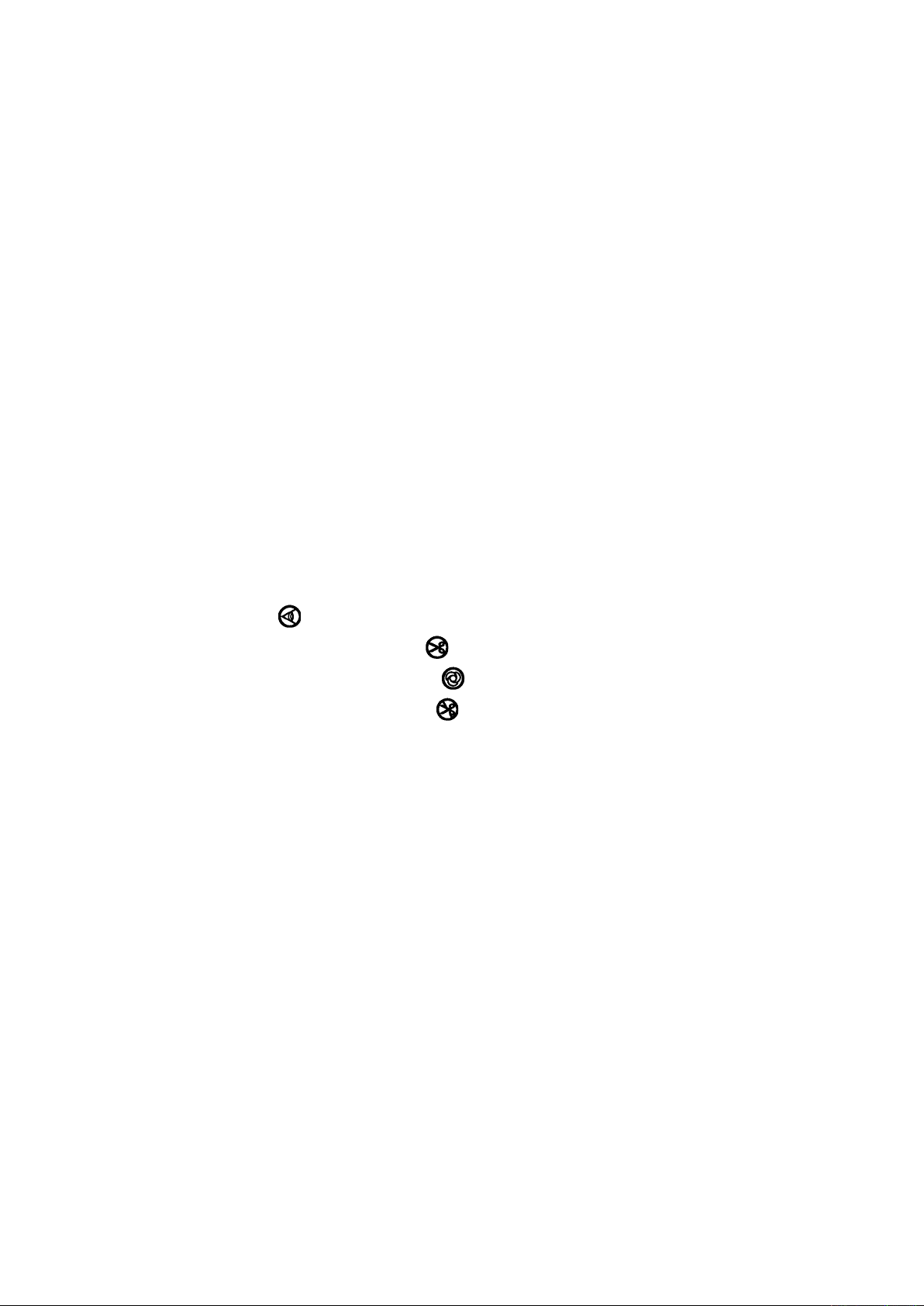
1-1. Installing IPOP circuit board
IPOP circuit
board
1
45˚
1
CN41
1) Loosen two screws in the front cover of control
box and open the front cover.
2) Remove connectors and ground wire of the circuit
board attached to the front cover.
3) Place the front cover at an angle of approximate
45°, draw it in the direction of arrow, and remove
it from the box main unit.
Do not draw the front cover forcibly since
there is the possibility that the click of front
cover is broken.
4)
Securely insert CN41 of IPOP circuit board supplied
as accessories to white connector CN41 on the
front cover circuit board from the upper side.
5) Fix IPOP circuit board with two screws 1 supplied
as accessories.
6) Place the front cover at an angle of approximate
45°, attach it to the box main unit, and attach
connectors and ground wire which have been
removed in step 2).
When removing IPOP c ircuit board, turn
OFF the power and remove it after 5 minutes
or more have passed.
1-2. Installing the panel
1
2
3
4
1) Install operation panel
using screws
supplied as accessories.
4
Do not disassemble the operation panel to
prevent it from breakage.
, washers
2
1
3
on the machine head
and spring washers
3
2
4
CN121
5
2) Set the panel cord same as the other machine
head cords, insert it to CN121 of the control box,
and lock it.
3) Put it together with other machine head cords and
bundle them with clip band 5.
4) Close the front cover and tighten two screws,
while taking care not to put the cords in the front
cover.
– 1 –

– 2 –
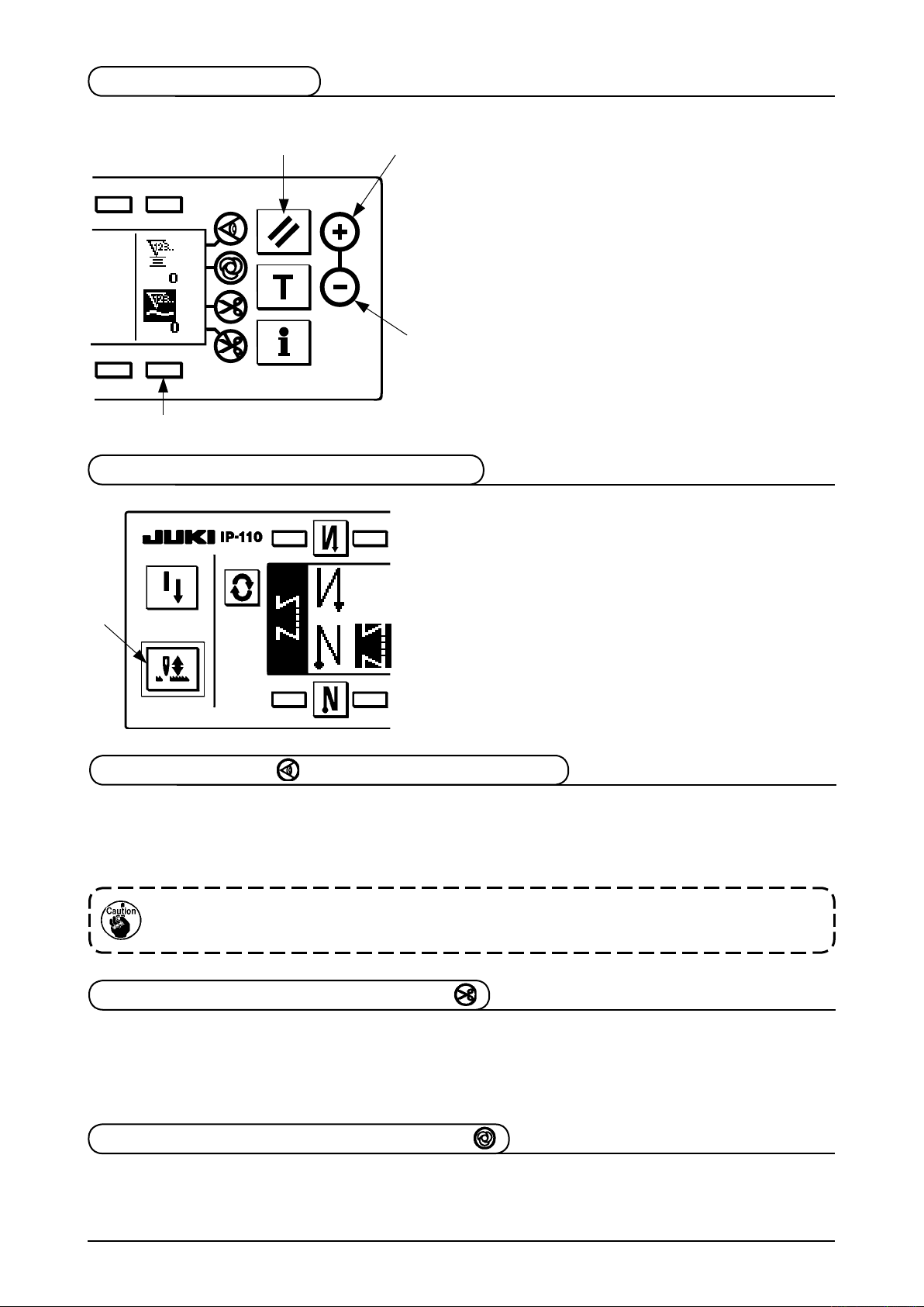
2. HOW TO USE THE OPERATION PANEL
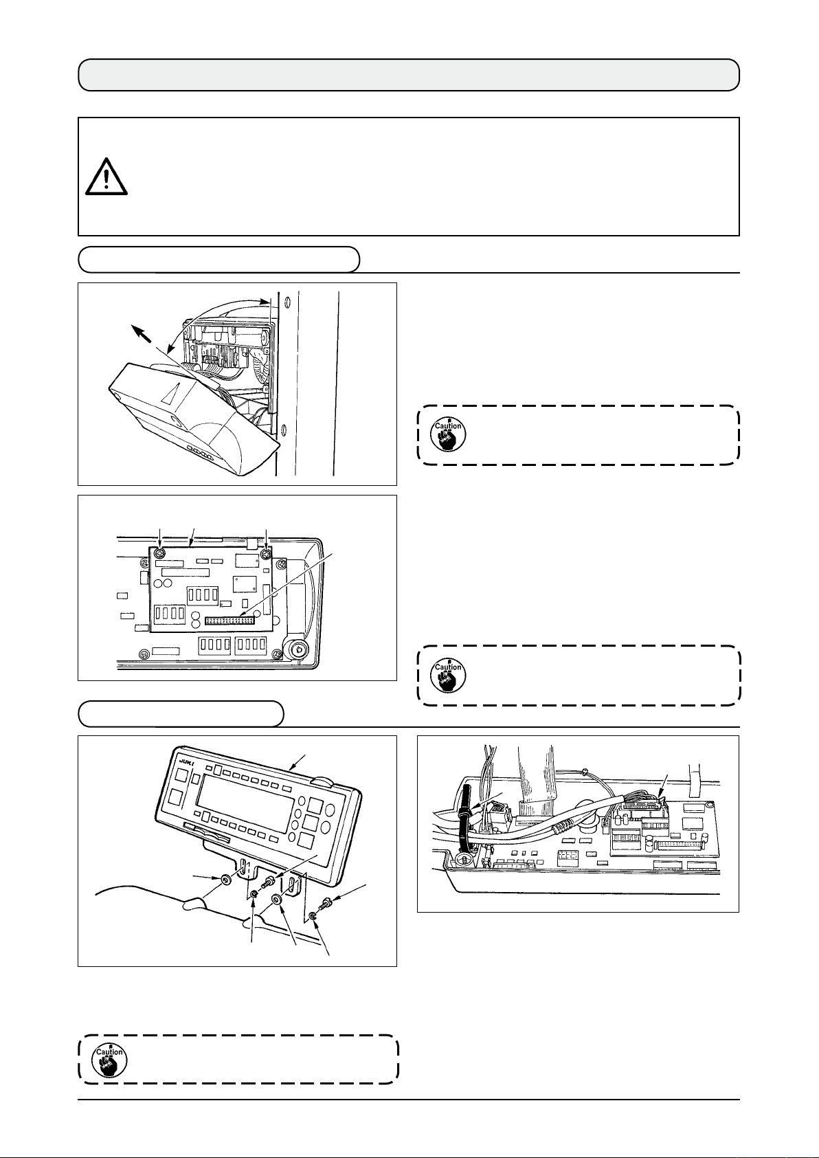
2-1. Names and functions of each components
!6
!8
!7
2
Re-sewing switch
1
Needle up/down compensating switch
2
Screen changeover switch
3
With/without reverse feed stitch at
4
sewing start switch
With/without reverse feed stitch at
5
sewing end switch
Reset switch
6
Teaching switch
7
1
3
5
8
9
!0
!1
!2
!3
!4
4
!4
Information switch
Material edge sensor switch
One-shot stitching switch
With/without automatic thread trimmer
switch
Thread trimming prohibiting switch
Counter value setting switch
Max.speed limitation variable resistor
!1
!0
9
!5
!2
Power display lamp
!5
Media cover
!6
Media slot (Media inserting opening)
!7
CompactFlash(TM)
!8
(Optional: Part No. 40000100)
8
6
!3
7
Re-sewing switch
1
Needle up/down
2
compensating switch
Unused
This is the switch to perform needle up/down compensating stitching.
(Needle up/down compensating stitching and one stitch compensating
stitching can be changed over with function setting No. 22.)
Screen changeover
3
This is the switch to change over the screen.
switch
With/without reverse feed
4
stitch at sewing start
switch
This is the switch to turn ON/OFF automatic reverse feed stitch at
sewing start.
* This switch cannot be used with the sewing machine which is not
provided with automatic reverse feed stitching device.
With/without reverse
5
feed stitch at sewing end
switch
This is the switch to turn ON/OFF automatic reverse feed stitch at
sewing end.
* This switch cannot be used with the sewing machine which is not
provided with automatic reverse feed stitching device.
Reset switch This is the switch to make the value of bobbin thread counter or
6
sewing counter the set value.
Teaching switch
7
Information switch This is the switch to perform various function settings.
8
Unused
Material edge sensor
9
switch
One-shot stitching switch
!0
With/without automatic
!1
thread trimmer switch
Thread trimming
!2
prohibiting switch
Counter value setting
!3
switch
Rendered effective when the material edge sensor is installed on
the machine.
Used for selecting whether or not the material edge sensor is used
during sewing.
When this switch is set to effective, the sewing machine
automatically operates up to the specied number of stitches.
When this switch is set to effective, the sewing machine
automatically performs thread trimming when the specied number
of stitches has been completed.
This switch prohibits all thread trimmings.
* This switch cannot be used with the sewing machine which is not
provided with the automatic thread trimming device.
This is the switch to set the value of bobbin thread counter or No. of
pcs. counter.
Max. speed limitation
!4
variable resistor
Power display lamp This lamp lights up when the power switch is turned ON.
!5
Media slot cover This is the cover for media inserting opening.
!6
Media slot (Media inserting opening)
!7
When moving the resistor in the left direction, max. speed is limited.
To open the cover, place your ngers on the notch located on the
side of the cover as shown in the gure and push the cover in the
direction of left slanting rear.
* There are some functions that are not able to be operated
with the cover opened. Do not close the cover unless the
CompactFlash(TM) is completely inserted.
To set the CompactFlash(TM), place the label face of the
CompactFlash(TM) to the front and insert the part that has a small
hole (place the notch of the edge to the rear) to the panel.
To remove the CompactFlash(TM), hold it between your ngers and
draw it out.
* When the inserting direction of the CompactFlash(TM) is wrong,
the panel and the CompactFlash(TM) may be damaged. Do not
insert anything other than the CompactFlash(TM).
– 3 –
– 4 –
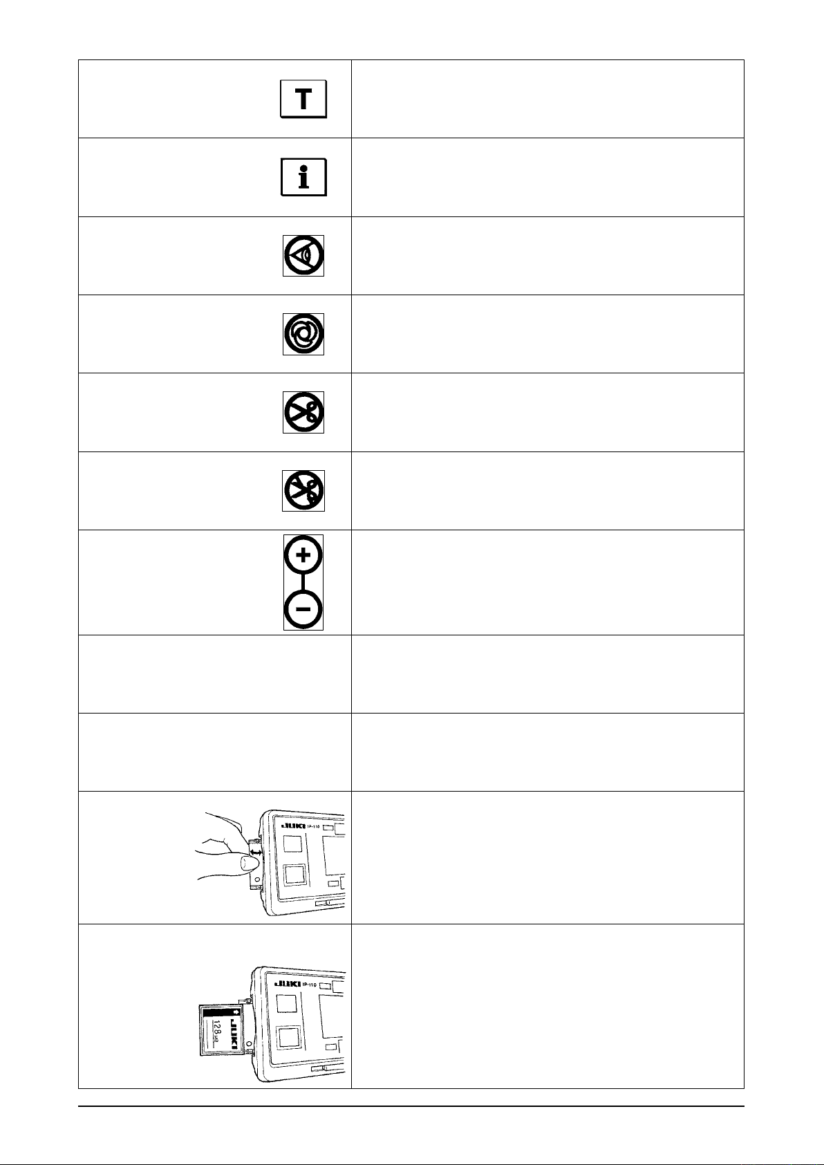
2-2. Adjusting the contrast of the operation panel display
1) Press in the direction of arrow mark the click of
section A of cord outlet cover
Light
2
A
Shade
3
1
the rear of operation panel
cover.
2) Turn LCD screen display brightness adjustment
var i able res i stor
(contrast) of LCD screen.
1. To prevent the operation panel from
breakage, do not touch the circuit board
pattern and the connector terminal.
2. Do not disassemble the operation panel
to prevent it from breakage.
assembled in
2
and remove the
1
t o adjust the brig h tness
3
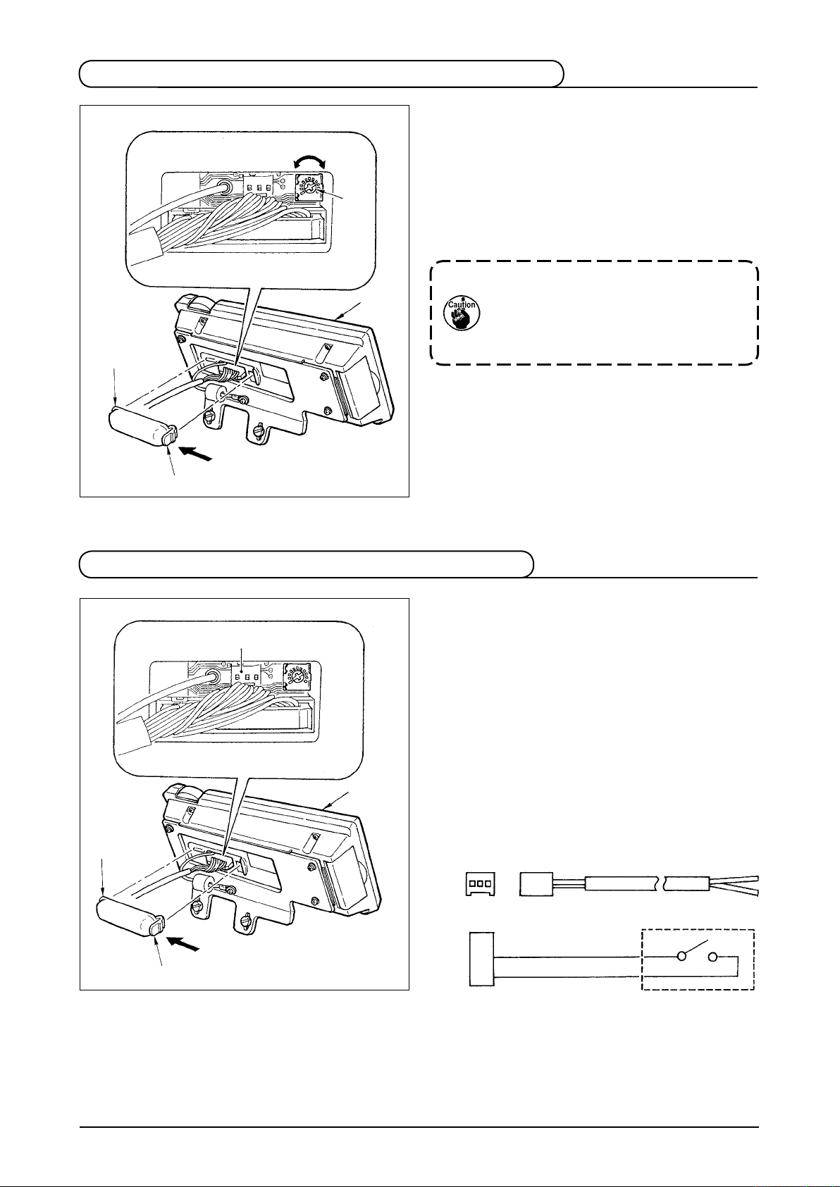
2-3. Production control switch connecting connector
1) Press in the direction of arrow mark the click of
section A of cord outlet cover
3
1
2
A
the rear of operation panel
cover.
2) Connect t h e optional r e l ay cable con n e ctor
to CN105
connecting connector.
Note) Prepare the switch main unit by the
customers or ask JUKI business ofce
about it.
Optional relay cable A (asm.)
JUKI Part No. 40008168
3 2 1
CN105
1
+ 5V
2
SW
GND
3
assembled in
2
and remove the
1
of the production control switch
3
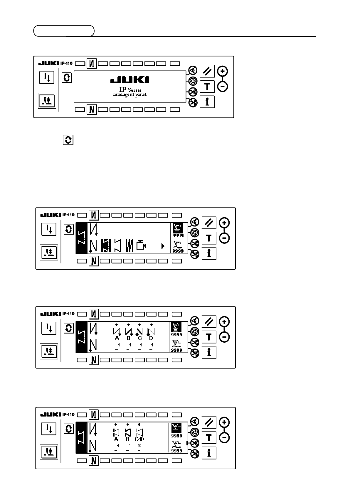
2-4. Screen list
WELCOME screen is displayed immediately after turning ON the power.
The screen immediately after WELCOME screen becomes the setting screen of pattern selection.
Every time
When connecting with the sewing machine of MO system, MF system, MH system and DLN system, or setting
1 of Function setting No. 6 Clutch motor function or 1 of the setting No. 106 Pattern control function, the output
display screen is displayed.
Pattern list screen
■
Selection of the respective shapes is performed.
Number of stitches of free stitching setting screen
■
Setting of number of stitches of free stitching is performed.
switch is pressed, the screen changes.
Number of stitches of constant dimension stitching setting screen
■
Setting of number of stitches of constant dimension stitching is performed.
– 5 –
– 6 –
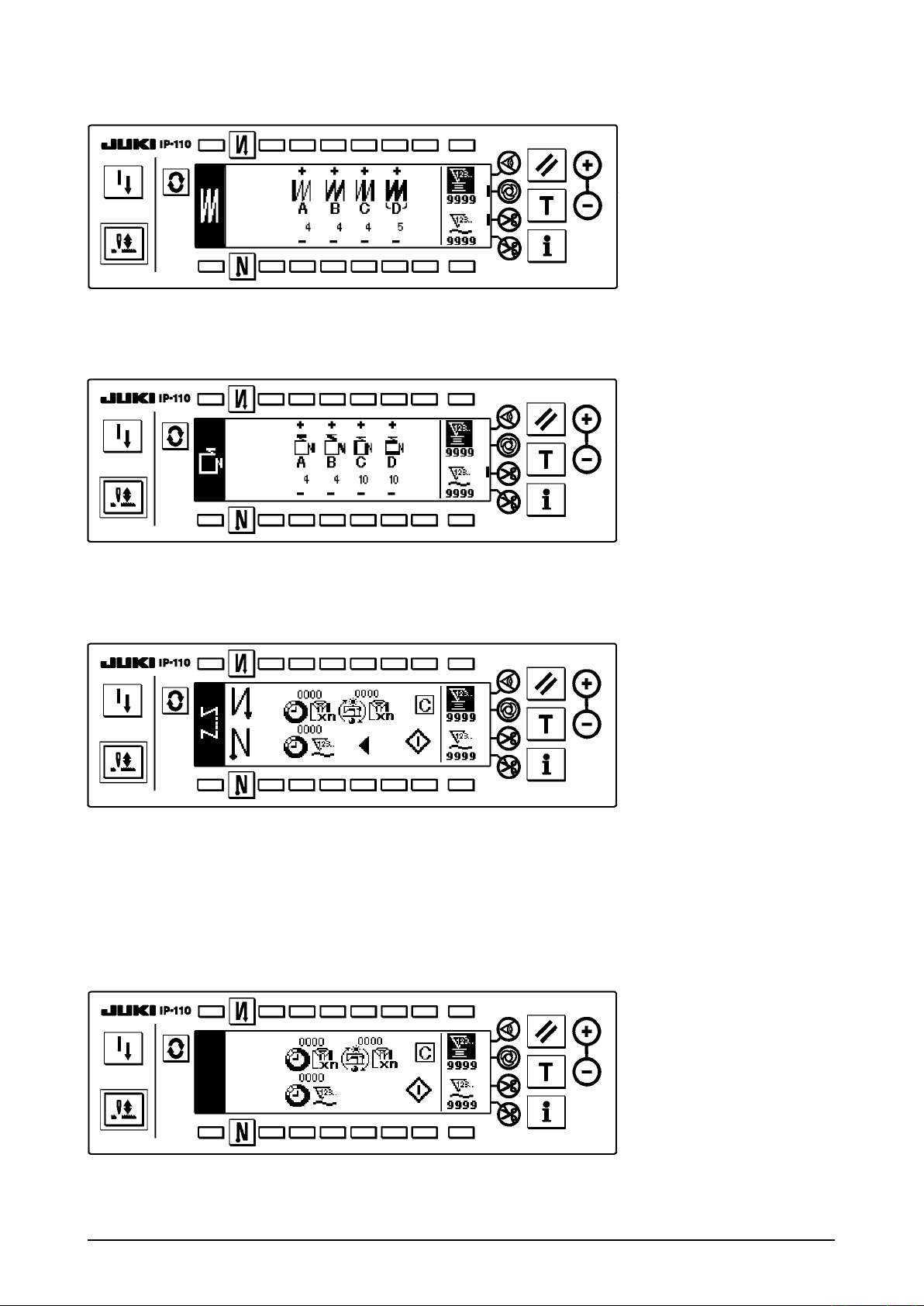
Number of stitches of overlapped stitching setting screen
■
Setting of number of stitches of overlapped stitching is performed.
Number of stitches of square stitching setting screen
■
Setting of number of stitches of square stitching is performed.
Output display screen
■
Final target set value, current target value and actual results up to now are displayed.
Output display screen (for sewing machines of MO system, MF system, MH system and DLN system)
■
Final target set value, current target value and actual results up to now are displayed.
In case of the sewing machines of MO system, MF system, MH system and DLN system, only this screen
is displayed.
When Function setting No. 76 Clutch motor function is set to 1 or the setting No. 106 Pattern control
function is set to 1, also only this screen is displayed.
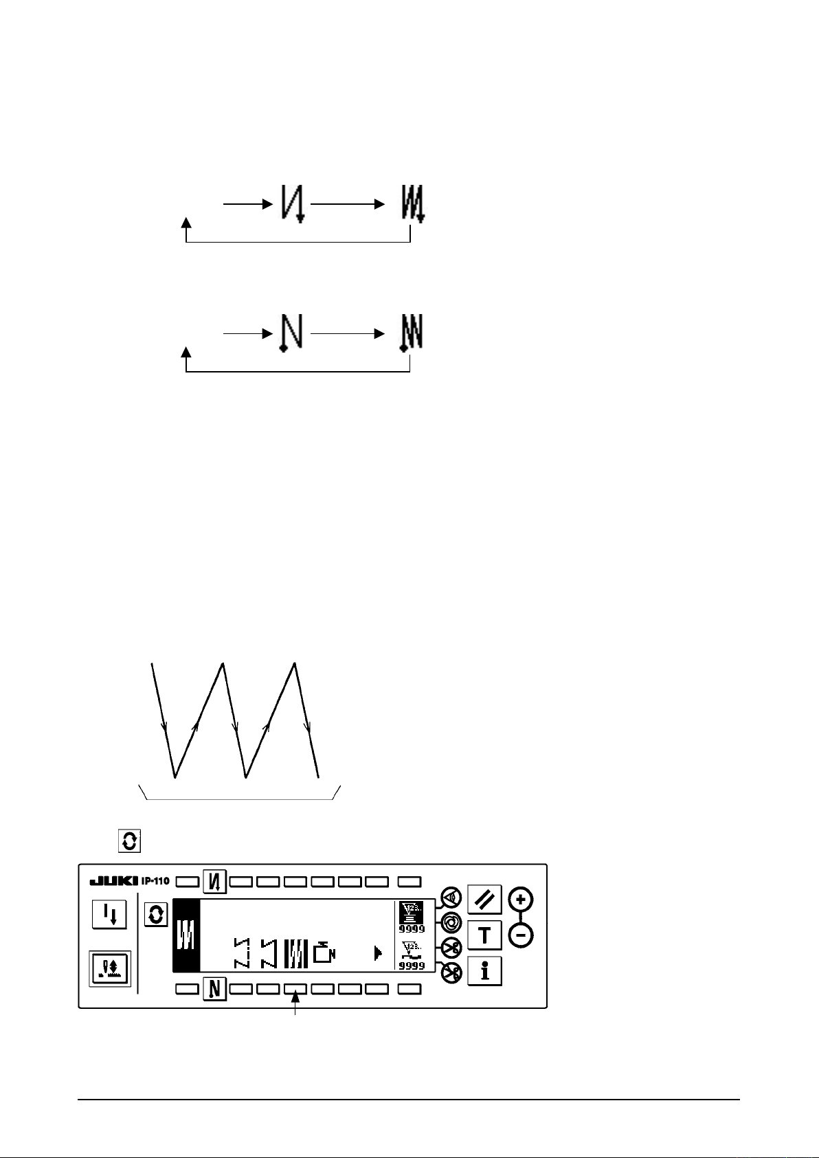
2-5. How to operate the operation panel for sewing stitching patterns
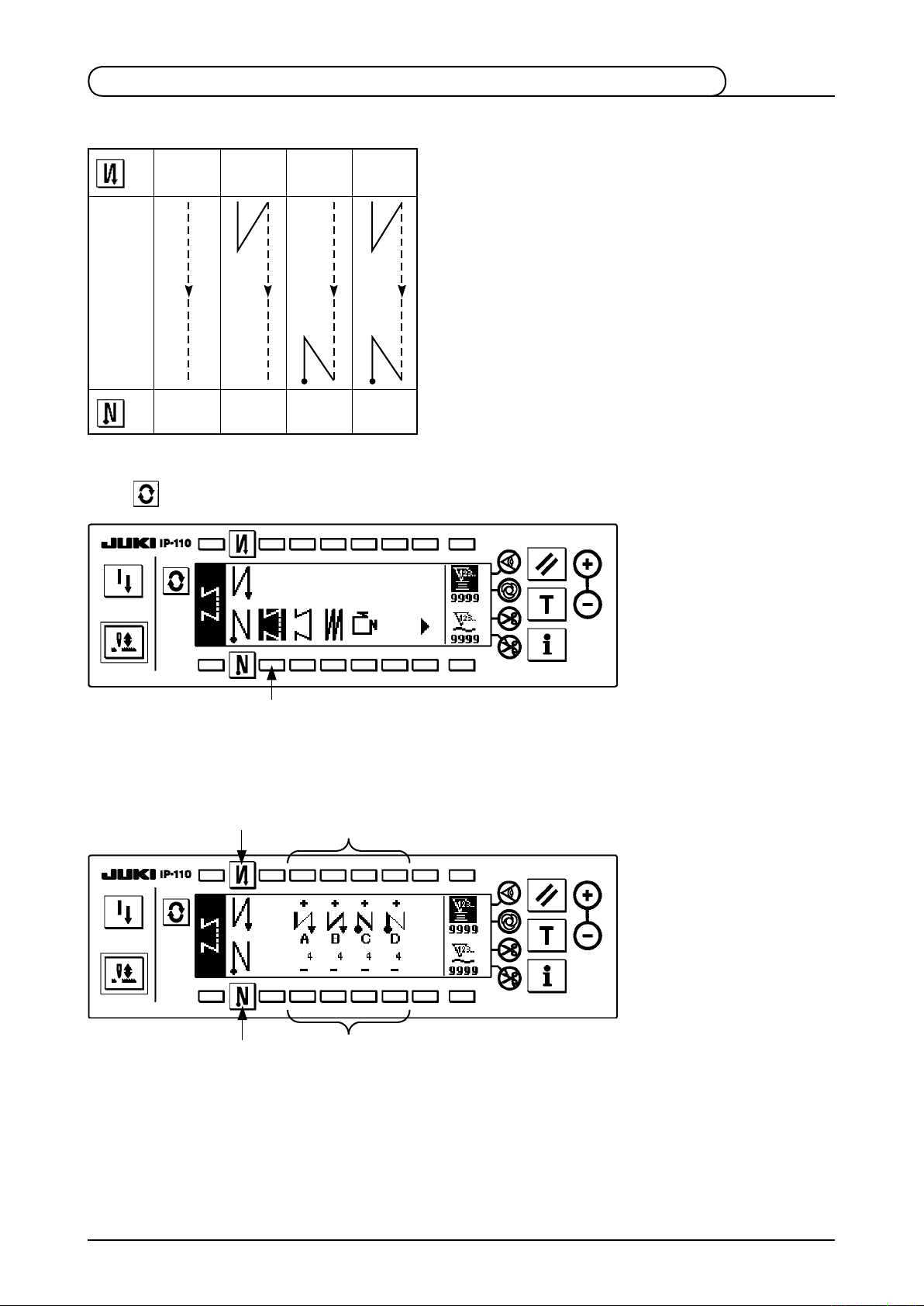
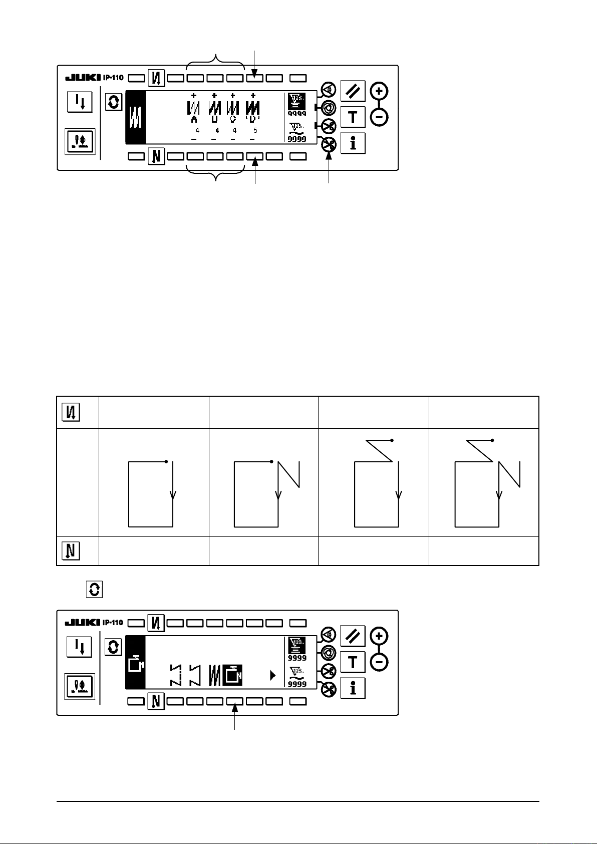
(1) Free stitching pattern
2
OFF ON ON
OFF
A
B
Sewing
pattern
C
D
OFF OFF
3
ON ON
Press to display the pattern list screen.
A
B
C
D
1
1) Press switch
to select the free stitching pattern, and the screen is automatically changed over to
1
the number of stitches of free stitching setting screen to display the number of stitches which has been
already set.
2
3
2) When changing the number of stitches, change it with switches
4
5
and 5 for setting the number of
4
stitches A through D.
(The range of the number of stitches that can be changed : 0 to 99 stitches)
– 7 –
– 8 –
3) Press switch
to set the reverse stitching at the start of sewing.
2
No setting Reverse stitching
at the start of sewing
4) Press switch
to set the reverse stitching at the end of sewing.
3
No setting Reverse stitching
at the end of sewing
(2) Constant dimension stitching pattern
2
Sewing
pattern
OFF ON ON
A
B
C D
C D C D
OFF
B
A
A
B
C D
B
A
Double reverse stitching
at the start of sewing
Double reverse stitching
at the end of sewing
3
OFF OFF
1) Press switch
ON ON
1
to select the constant dimension stitching pattern, and the screen is automatically
1
Press to display the pattern list screen.
changed over to the number of stitches of constant dimension stitching setting screen to display the
number of stitches which has been already set.
2
4
6
!0
3
5
7
8
9
2) When changing the number of stitches of the reverse stitching, change it with switches
setting the number of stitches of A and B.
In addition, when changing the number of stitches of the constant dimension stitching, change it with
switches 6 and
(The range of the number of stitches that can be changed : A and B = 0 to 19 stitches, C D = 0 to 500 stitches)
for setting the number of stitches of C D.
7
and 5 for
4
3) Press switch
4) Press switch 3 to set the reverse stitching at the end of sewing.
5)
When automatic thread trimming switch
processes C D have been completed. (When setting the reverse stitching at the end of sewing, thread
trimming is automatically performed after the reverse stitching at the end of sewing has been completed.
When automatic thread trimming switch 8 is not selected, press the touch-back switch after processes C
D have been completed, and the sewing machine rotates at low speed. (Compensation stitching operation)
In addition, when the pedal is returned to the neutral position and the front part of it is depressed again,
the sewing can be continued regardless of the setting of the number of stitches.
6) When thread trimming prohibiting switch 9 is selected, the sewing machine will stop with the needle up
without performing thread trimming.
7) When one-shot automatic stitching switch
without a break by depressing the front part of the pedal.
to set the reverse stitching at the start of sewing.
2
No setting
No setting Reverse stitching
Reverse stitching
at the start of sewing
at the end of sewing
8
!0
Double reverse stitching
at the start of sewing
Double reverse stitching
at the end of sewing
is selected, thread trimming is automatically performed after
is selected, automatic sewing is performed at the set speed
(3) Overlapped stitching pattern
A C C
B B
D
Press to display the pattern list screen.
1
1) Press switch 1 to select the overlapped stitching pattern, and the screen is automatically changed over to
the number of stitches of overlapped stitching setting screen to display the number of stitches which has
already been set.
– 9 –
– 10 –
2
4
3 5 6
2) When changing the number of stitches, change it with switches
2
and
for setting the number of
3
stitches for processes A through C. To change the number of times of the whole processes, change it with
switches
4
and
for setting the number of processes D.
5
(The range of the number of stitches A, B and C that can be changed : 0 to 19 stitches. The range of the
number of processes D that can be changed : 0 to 9 times)
3) Depress the front part of the pedal once, and the sewing machine will repeat the normal stitching and
reverse stitching as many as the number of specied times. Then the sewing machine will automatically
make the thread trimmer actuate and will stop to complete the overlapped stitching procedure. (The oneshot automatic stitching cannot be turned OFF.)
4) When thread trimming prohibiting function
is selected, the machine will stop with the needle up upon
6
completion of the overlapped stitching procedure without performing thread trimming.
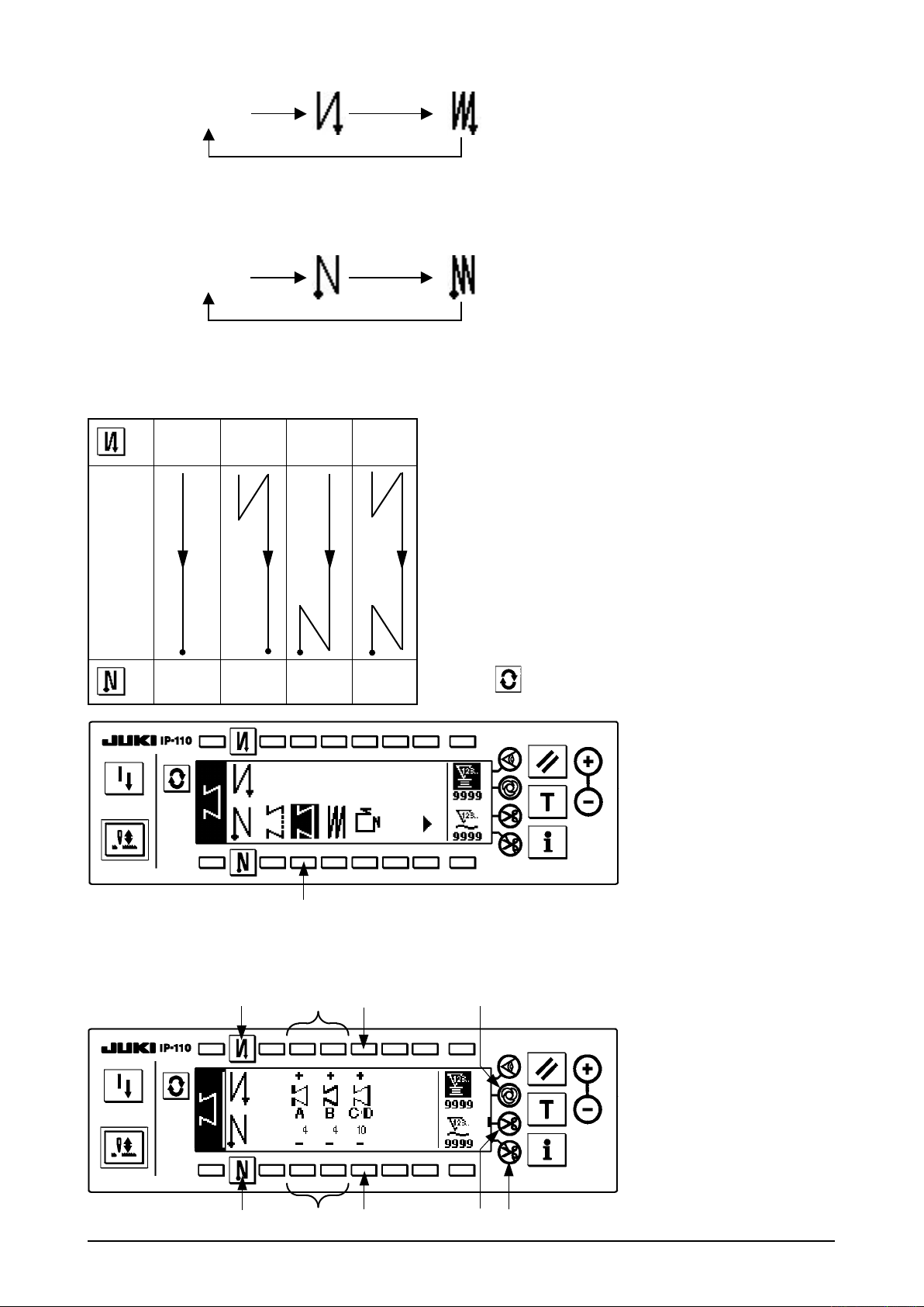
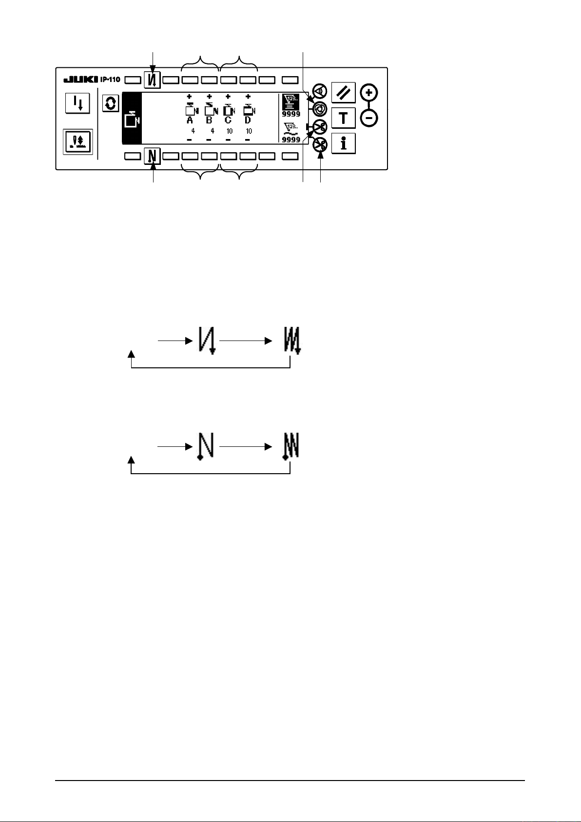
(4) Square stitching pattern
2
Sewing
pattern
OFF
D
C
C
D
C
A
B
C
OFFON ON
A
B
D
C
C
C
A
B
D
A
B
C
3
D
OFF
D
D
ONOFF
D
ON
Press to display the pattern list screen.
1
1) Press switch 1 to select the square stitching pattern, and the screen is automatically changed over to
the number of stitches of square stitching setting screen to display the number of stitches which has been
already set.
2
4
6
!0
53 9
2) When changing the number of stitches of reverse stitching, change it with switches
the number of stitches of A and B.
In addition, when changing the number of stitches of square stitching, change it with switches 6 and 7
for setting the number of stitches of C and D.
(The range of the number of stitches that can be changed : A and B = 0 to 19 stitches, C and D = 0 to 99
stitches)
3) Press switch
No setting Reverse stitching
4) Press switch
to set the reverse stitching at the start of sewing.
2
at the start of sewing
to set the reverse stitching at the end of sewing.
3
7 8
Double reverse stitching
at the start of sewing
and 5 for setting
4
No setting Reverse stitching
at the end of sewing
5) The sewing machine automatically stops after completion of the process at processes C and D. At this
time, the sewing machine rotates at low speed when the touch-back switch is pressed (compensation
stitching operation). In addition, when the pedal is returned to the neutral position and the front part of it is
depressed again, the sewing can be continued regardless of the setting of the number of stitches.
6) When automatic thread trimming switch 8 is selected, thread trimming is automatically performed after
completion of the last process. (When the reverse feed stitching at the end of sewing is set, the reverse
feed stitching at the end of sewing becomes the last process, and automatic thread trimming is performed
after completion of the process.)
7) When thread trimming prohibiting switch 9 is selected, the sewing machine will stop with the needle up
without performing thread trimming.
8) When one-shot automatic stitching switch
without a break by depressing the front part of pedal at processes C and D.
9) When the sewing machine is provided with auto-lifter, the presser foot automatically goes up after
completion of the process at processes C and D.
Double reverse stitching
at the end of sewing
is selected, automatic sewing is performed at the set speed
!0
– 11 –
– 12 –
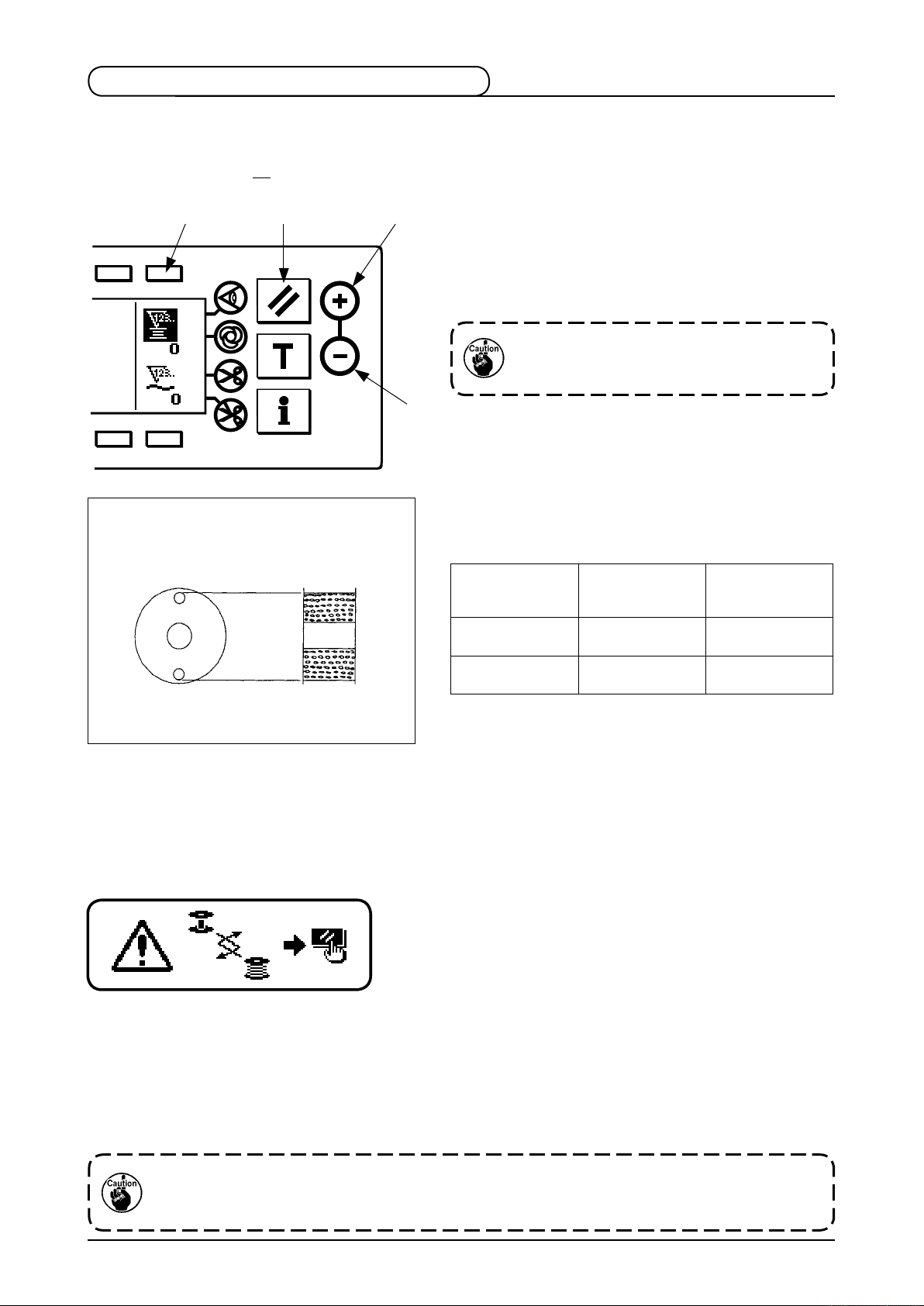
2-6. How to use the bobbin thread counter
The machine detects the number of stitches. The preset value on the bobbin thread counter is subtracted in
accordance with the number of stitches detected. (Every time the detector detects 10 stitches, 1 is subtracted
from the preset value on the bobbin thread counter.) When the value on the counter becomes a minus value
........
as (
→
change the bobbin thread has come.
Initial value on the bobbin thread counter
for reference
0 → –1), the buzzer (peeps three times) and the pop-up display inform that the time to
1
→
1 2
3
1) Press switch
to select the bobbin thread counter.
1
Then press counter reset switch
to return the
2
value indicated on the bobbin thread counter to the
initial value (it has been factory-set to “0” at the time
of delivery).
The bobbin thread counter cannot be reset
during sewing. In this case, make the thread
trimmer actuate once.
4
2) Set an init ial v alue u sing c ounter value setti ng
switches 3 and 4.
The table below gives the initial setting values for
reference when the bobbin is wound with thread to the
extent that the pinhole in the outside of the bobbin case
is reached as shown in the gure on the left side.
Length of thread
Thread used
Polyester spun
thread #50
Cotton thread #50 31 m
wound round the
bobbin
36 m
Thread tension rate 100 %
Value on bobbin
thread counter
1200
(stitch length : 3 mm)
1000
(stitch length : 3 mm)
* Actually, the bobbin thread counter is affected by
the material thickness and the sewing speed. So,
adjust the initial value of the bobbin thread counter in
accordance with the operating conditions.
3) Once the initial value is specied, start the sewing machine.
4) When a minus value is shown on the counter, the buzzer peeps three times and the pop-up display
appears, replace the bobbin thread.
Bobbin thread replacement warning pop-up
5) After the bobbin thread has been properly replaced, press counter reset switch 2 to return the value on
the bobbin thread counter to the initial value. Now, re-start the sewing machine.
6) If the remaining amount of bobbin thread is excessive or the bobbin thread runs out before the bobbin
thread counter indicates a minus value, adjust the initial value appropriately using counter value setting
switches 3 and 4.
If the remaining amount of bobbin thread is excessive ..... Increase the initial value using the “+” switch.
If the remaining amount of bobbin thread is insufcient .... Decrease the initial value using “–” switch.
If the bobbin thread counter is used in combination with the bobbin thread remaining amount
detecting device, the bobbin thread counter indicates the number of times of detection of the bobbin
thread remaining amount detecting device. So, be sure to use the device after carefully reading the
Instruction Manual for the bobbin thread remaining amount detecting device.
2-7. Sewing counter
Count-up is performed every time thread trimming is performed. (0
4
1
2
After selecting the sewing counter by pressing switch 1,
the counter value can be modified using counter value
setting switches 2 and
value returns to "0" by pressing counter reset switch
3
2-8. Needle up/down compensation switch
Every time needle up/down compensation switch 1
is pressed, the needle goes up when it is in its lowest
position or comes down when it is in its highest position.
This compensates the stitch by a half of the predetermined
stitch length.
Note, however, that the machine does not run
1
continuously at a low speed even if you keep the switch
held pressed.
Also, note that the needle up/down compensation switch
is inoperative after turning the handwheel by hand.
Thread trimming is operative only at the time of stitch
compensation after depressing the front part of the pedal
once.
→
1
...........
→
2
3
→ 9999)
. In addition, the sewing counter
4
.
2-9. ON/OFF switch of the material edge sensor
• When the material edge sensor, which is optionally available, is connected to the operation panel, the ON/
OFF switch of the material edge sensor becomes effective.
• If the material edge sensor is specied, the sewing machine will automatically stop running or perform
thread trimming when the sensor detects the material edge.
If the material edge sensor is used in combination with the operation panel, carefully read the
Instruction Manual for the material edge sensor beforehand.
2-10. Automatic thread trimming switch
• This switch is used to automatically actuate the thread trimmer in a process where the sewing machine
automatically stops or when the material edge sensor is used.
(if the automatic reverse stitching (for end) is specied, the thread trimmer will actuate after the sewing
machine completes the automatic reverse stitching (for end).)
2-11. One-shot automatic stitching switch
• This switch is used, in the constant-dimension stitching mode, rectangular stitching mode, or in the process
where the material edge sensor is specied, to make the sewing machine automatically perform sewing at
the specied speed until the end of the process is reached only by driving the sewing machine once.
– 13 –
 Loading...