


INSTRUCTION MANUAL
* "CompactFlash(TM)" is the registered trademark of SanDisk Corporation, U.S.A.
ENGLISH
CONTENTS
1. INSTALLING THE OPERATION PANEL ................................................................... 1
2. CONNECTING THE CORD ........................................................................................ 2
3. HOW TO USE THE OPERATION PANEL ................................................................. 3
3-1. Names and functions of each components .....................................................3
3-2. Adjusting the contrast of the operation panel display ....................................5
3-3. Production control switch connecting connector ...........................................5
4. STANDARD PANEL ................................................................................................... 6
4-1. Basic screen ........................................................................................................6
4-2. How to operate the operation panel for sewing stitching patterns ...............8
(1) Reverse stitching pattern ...................................................................................................................8
(2) Overlapped stitching pattern ...........................................................................................................10
(3) Programmed stitching pattern .........................................................................................................11
(4) Cycle sewing pattern ........................................................................................................................15
4-3. How to use the bobbin thread counter ...........................................................17
4-4. No. of pcs. counter ...........................................................................................18
4-5. Re-sewing switch ..............................................................................................18
4-6. Needle up/down compensation switch ...........................................................19
4-7. ON/OFF switch of the material edge sensor .............................................19
4-8. Automatic thread trimming switch ............................................................19
4-9. One-shot automatic stitching switch ........................................................19
4-10. Thread trimming prohibition switch ........................................................20
4-11. Key lock ...........................................................................................................20
4-12. Information ......................................................................................................21
(1) Maintenance management function ................................................................................................21
(2) Production control function .............................................................................................................25
(3) Working measurement function ......................................................................................................27
4-13. Setting for functions .......................................................................................29
(1) How to change over to the function setting mode ........................................................................29
(2) Function setting list ..........................................................................................................................32
5. PANEL FOR LH-4168/4188 ..................................................................................... 37
5-1. Basic screen ......................................................................................................37
5-2. How to operate the operation panel for sewing stitching patterns .............41
(1) Reverse stitching pattern .................................................................................................................41
(2) Overlapped stitching pattern ...........................................................................................................43
(3) Corner pattern ...................................................................................................................................44
(4) Step pattern .......................................................................................................................................50
(5) Cycle sewing pattern ........................................................................................................................53
5-3. How to use the bobbin thread counter ...........................................................54
5-4. No. of pcs. counter ...........................................................................................55
5-5. Re-sewing switch ..............................................................................................56
5-6. Needle up/down compensation switch ...........................................................57

5-7. ON/OFF switch of the material edge sensor .............................................57
5-8. Automatic thread trimming switch ............................................................57
5-9. One-shot automatic stitching switch ........................................................57
5-10. Thread trimming prohibition switch ........................................................58
5-11. Key lock ...........................................................................................................58
5-12. Information ......................................................................................................59
(1) Maintenance management function ................................................................................................59
(2) Production control function .............................................................................................................63
(3) Working measurement function ......................................................................................................65
5-13. Setting for functions .......................................................................................67
(1) How to change over to the function setting mode ........................................................................67
(2) Function setting list ..........................................................................................................................70
(3) Communication mode ......................................................................................................................77
6. EXTERNAL INTERFACE .........................................................................................81
7. ERROR DISPLAY ....................................................................................................81
7-1. Error code list (Error display in panel) ...........................................................82
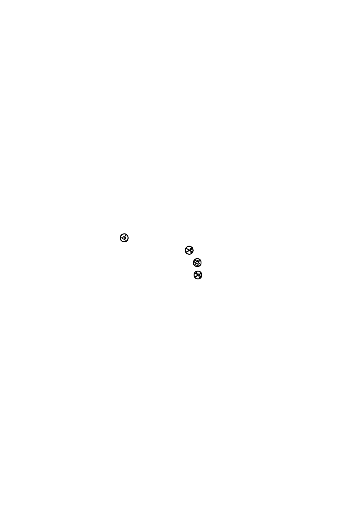
1. INSTALLING THE OPERATION PANEL
WARNING :
To protect against possible personal injury due to abrupt start of the machine, be sure to start the
following work after turning the power off and ascertaining that the motor is at rest.
Type B (Type name plate TYPE B0*)
1
Type C (Type name plate TYPE C0*)
2
3
4
2
3
4
1
2
4
3
5
5
1) Attach operation panel 1 to the machine head using screw 2, plain washer 3, toothed lock washer 4
and spacer 5 (for type C) supplied with the operation panel. Select and use screw 2 referring to the table.
2) The positions of the holes in the bracket for installing the operation panel are different from each other
according to the respective models. Refer to the table below.
IP-110 / bracket type classied by model correspondence table
Type B
1
2
3
No. Mounted machine head Bracket type
1 DDL-9000 Type B
2 DLN-9010 Type B
3 LH-31
4 LZ-228*N Type B
5 DDL-5550N Type C
6 DDL-8700 Type C
7 DLN-5410N Type C
8 DLU-5494N Type C
9 LH-41
** ,
**
LH-35
**
5
4
Type B
Type B
Installing
hole used
2-4
2-4
1-5
3-4
1-3
1-3
1-3
1-3
2-4
Type C
2
1
Part No. of screw Remarks
SS4121415SP(3/16-28)
SS4121415SP(3/16-28)
SS6111210SP(11/64-40)
SS4121415SP(3/16-28)
SS7121410SN(3/16-24)
SS7121410SN(3/16-24)
SS7121410SN(3/16-24)
SS7121410SN(3/16-24)
SM6051000SP(M5)
3
To be xed on the exclusive
bracket for installing standard
panel
Use 2 – 3 in case of optional
unit (V0 and the like).
Use screw and washers that
are used for machine head.
– 1 –
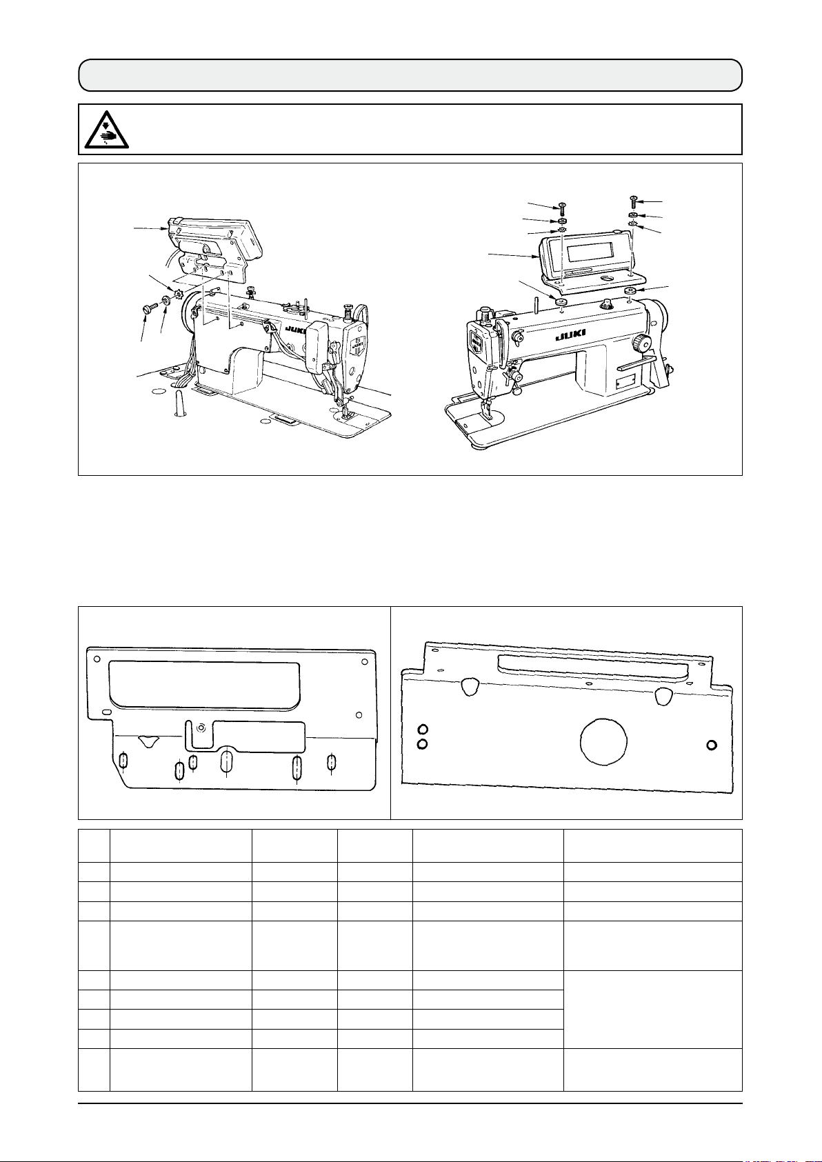
2. CONNECTING THE CORD
WARNING :
Turn OFF the power and start the work after 5 minutes or more have passed so as to prevent
accidents caused by abrupt start of the sewing machine.
2
A
1
1) Pass cord 1 and FG cord 3 (for type C) of the
operation panel through hole A in the machine
table to route it to the underside of the table.
3
4
3
1
2) Connect the connector of cord 1 to connector
CN34 2 in the control box.
Bottom surface of table
5
3) For type C, x FG cord 3 to the power switch with wood screw 4 supplied with the panel as accessories.
Wire FG cord 3 after bundling it with the power cable and the like with cable clip band 5 supplied with
the panel as accessories.
– 2 –
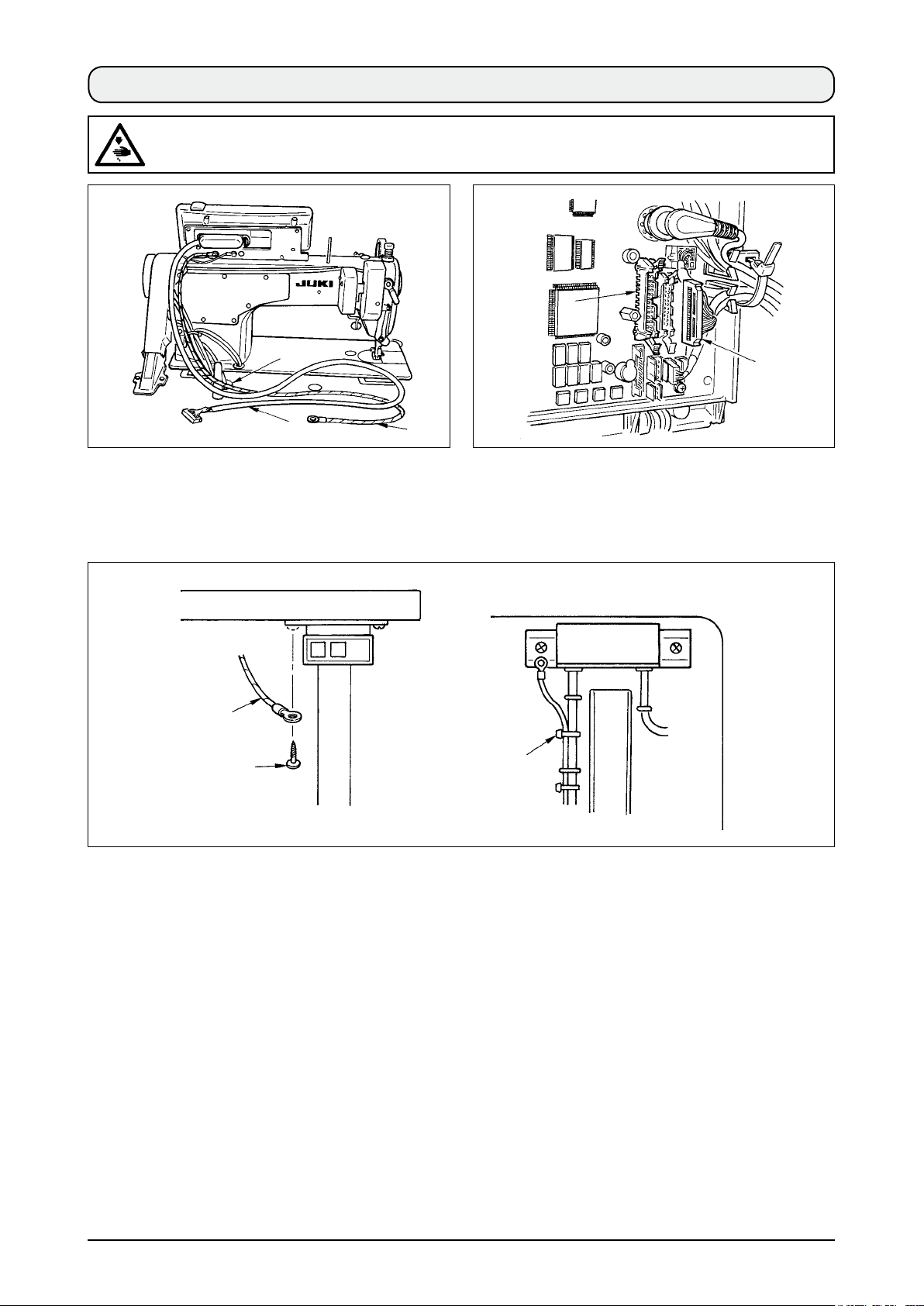
3. HOW TO USE THE OPERATION PANEL
3-1. Names and functions of each components
!8
1
!6
!7
3
4
!0
9
!5
6
!3
7
2
Re-sewing switch
1
Needle up/down compensating switch
2
Screen changeover switch
3
With/without reverse feed stitch at sewing start switch
4
With/without reverse feed stitch at sewing end switch
5
Reset switch
6
Teaching switch
7
Re-sewing switch
1
Needle up/down
2
5
compensating switch
Screen changeover
3
switch
!4
Information switch
8
Material edge sensor switch
9
One-shot stitching switch
!0
With/without automatic thread trimmer switch
!1
Thread trimming prohibiting switch
!2
Counter value setting switch
!3
Max.speed limitation variable resistor
!4
!1
!2
8
Power display lamp
!5
Media cover
!6
Media slot
!7
(Media inserting opening)
CompactFlash(TM)
!8
(Optional : Part No.40000100)
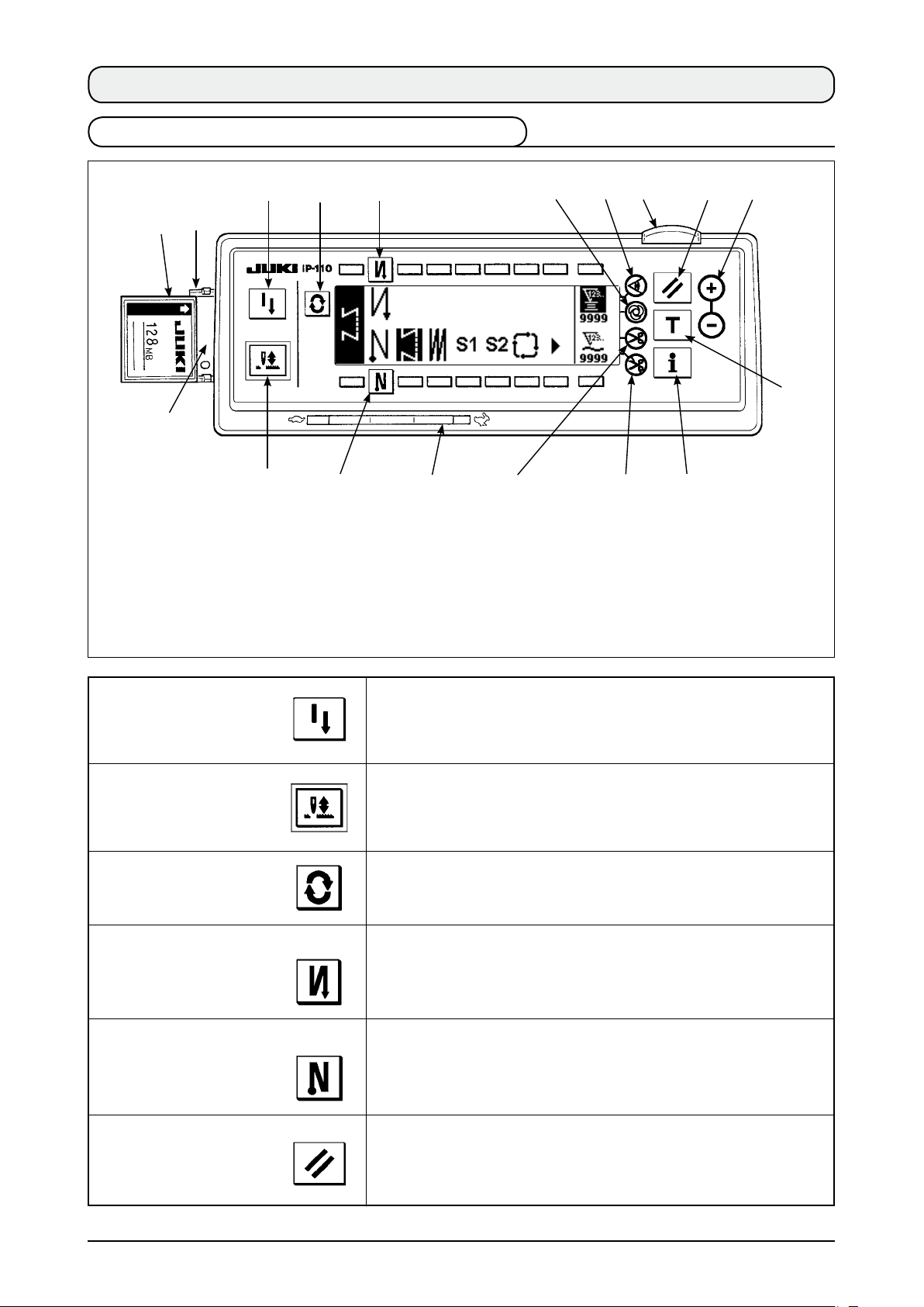
This switch is used to continue sewing from the step on the way
after replacing bobbin thread when bobbin thread has run out
during program stitching step.
This is the switch to perform needle up/down compensating stitching.
(Needle up/down compensating stitching and one stitch compensating
stitching can be changed over with function setting No. 22.)
This is the switch to change over the screen.
With/without reverse feed stitch
4
at sewing start switch
With/without reverse feed stitch
5
at sewing end switch
Reset switch
6
This is the switch to turn ON/OFF automatic reverse feed stitch
at sewing start.
* This switch cannot be used with the sewing machine which is
not provided with automatic reverse feed stitching device.
This is the switch to turn ON/OFF automatic reverse feed stitch
at sewing end.
* This switch cannot be used with the sewing machine which is
not provided with automatic reverse feed stitching device.
This is the switch to make the value of bobbin thread counter or
sewing counter the set value.
– 3 –
Teaching switch
7
Information switch
8
Material edge sensor switch
9
One-shot stitching switch
!0
With/without automatic
!1
thread trimmer switch
Thread trimming
!2
prohibiting switch
This is the switch to set the setting of the number of stitches with
the value of number of stitches which has been actually sewn.
This is the switch to perform various function settings.
Rendered effective when the material edge sensor is installed on
the machine.
Used for selecting whether or not the material edge sensor is
used during sewing.
When this switch is set to effective at the time of program
stitching, the sewing machine automatically operates up to the
specied number of stitches.
When this switch is set to effective at the time of program stitching,
the sewing machine automatically performs thread trimming when
the specied number of stitches has been completed.
This switch prohibits all thread trimmings.
* This switch cannot be used with the sewing machine which is
not provided with the automatic thread trimming device.
Counter value setting
!3
switch
Max. speed limitation variable
!4
resistor
Power display lamp
!5
Media slot cover
!6
Media slot
!7
(Media inserting opening)
This is the switch to set the value of bobbin thread counter or No.
of pcs. counter.
When moving the resistor in the left direction, max. speed is limited.
This lamp lights up when the power switch is turned ON.
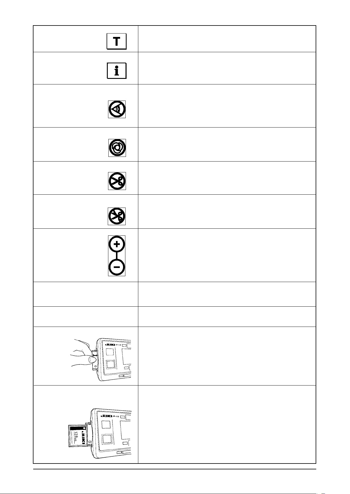
This is the cover for media inserting opening.
To open the cover, place your nger on the notch located on the
side of the cover as shown in the gure and push the cover in the
direction of left slanting rear.
* There are some functions that are not able to be operated
with the cover opened. Do not close the cover unless the
CompactFlash(TM) is completely inserted.
To set CompactFlash(TM), place the label face of the
CompactFlash(TM) to the front and insert the part that has a
small hole (place the notch of the edge to the rear) to the panel.
To remove the CompactFlash(TM), hold it between your ngers
and draw it out.
* When the inserting direction of the CompactFlash(TM) is wrong,
the panel and the CompactFlash(TM) may be damaged. Do not
insert anything other than the CompactFlash(TM).
– 4 –
3-2. Adjusting the contrast of the operation panel display
1) Press in the direction of arrow mark the click of
section A of cord outlet cover 2 assembled in
the rear of operation panel 1 and remove the
cover.
2) Turn LCD screen display brightness adjustment
variable resistor 3 to adju s t th e brig h t n es s
(contrast) of LCD screen.
1. To prevent the operati on panel
from breakage, do not touch the
ci rcu it bo ard p a tt e rn an d t he
connector terminal.
2. Do not disassemble the operation
panel to prevent it from breakage.
2
A
Light
Shade
3
1
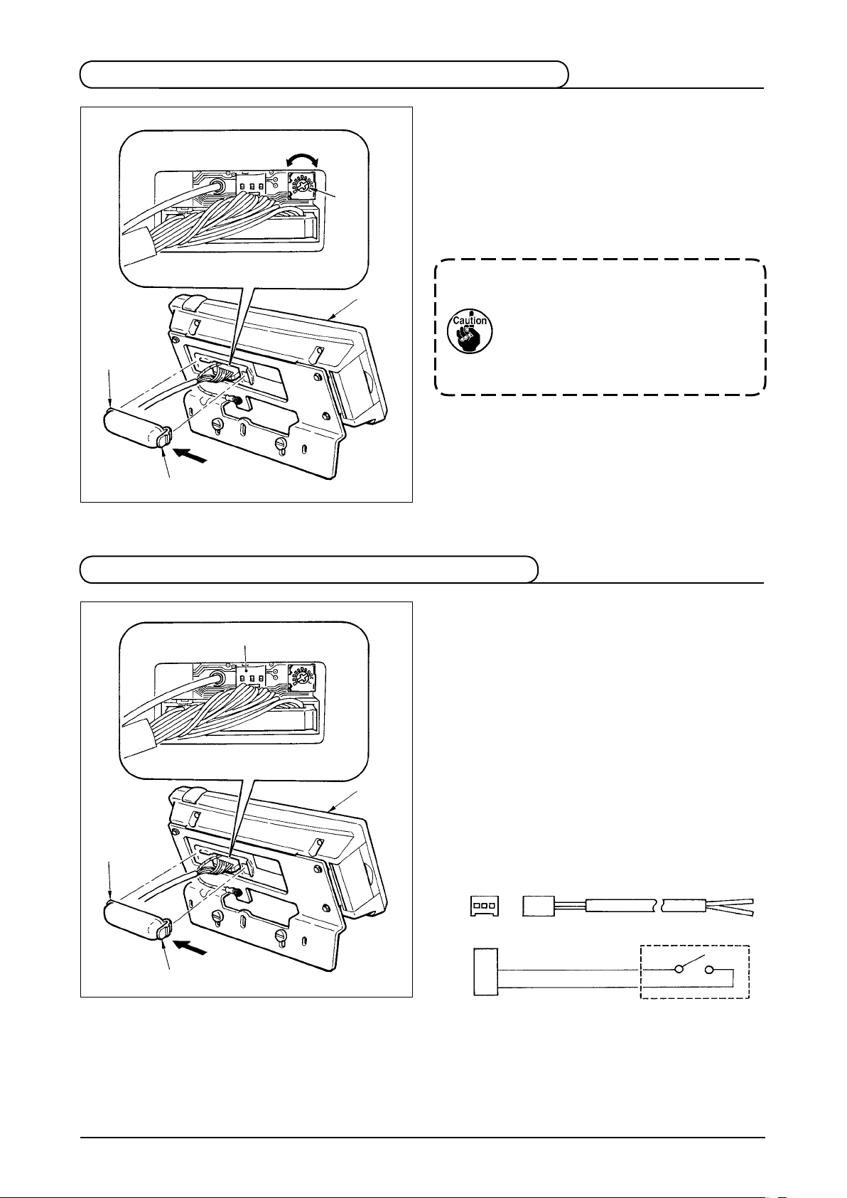
3-3. Production control switch connecting connector
1) Press in the direction of arrow mark the click of
3
1
2
A
section A of cord outlet cover 2 assembled in
the rear of operation panel 1 and remove the
cover.
2) C o n ne ct the opti o na l r el ay cable co n ne c to r
to CN105 3 of the product ion control swi tch
connecting connector.
Note) Prepare the switch main unit by the
customers or ask JUKI business ofce
about it.
Optional relay cable A (asm.)
JUKI Part No. 40008168
3 2 1
CN105
1
+ 5V
2
SW
3
GND
– 5 –
4. STANDARD PANEL
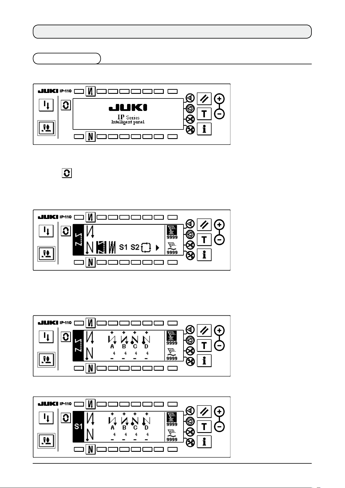
4-1. Basic screen
WELCOME screen is displayed immediately after turning ON the power.
The screen immediately after WELCOME screen becomes the screen that performs the sewing pattern
setting that was selected when turning OFF the power previously.
Every time switch is pressed, the screen changes.
Pattern list screen
■
Selection of the respective shapes is performed.
Number of stitches of back tuck stitching setting screen
■
Setting of number of stitches of reverse stitching is performed.
When reverse stitching pattern is selected
<
When programmed stitching pattern 1 is selected
<
>
>
– 6 –
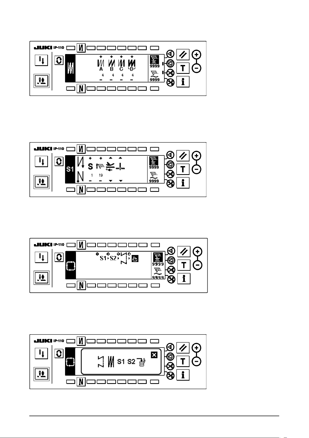
Number of stitches of overlapped stitching setting screen
■
Setting of number of stitches of overlapped stitching is performed.
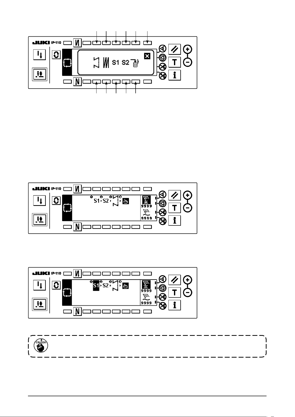
Programmed stitching setting screen
■
Setting of the respective conditions of programmed stitching is performed.
When programmed stitching pattern 1 is selected
<
>
Cycle sewing setting screen
■
Setting of the step of cycle sewing is performed.
Cycle sewing pattern setting pop-up
■
Setting of the pattern of cycle sewing is performed.
– 7 –
Output display screen
■
Final target set value, current target value and actual results up to now are displayed.
4-2. How to operate the operation panel for sewing stitching patterns
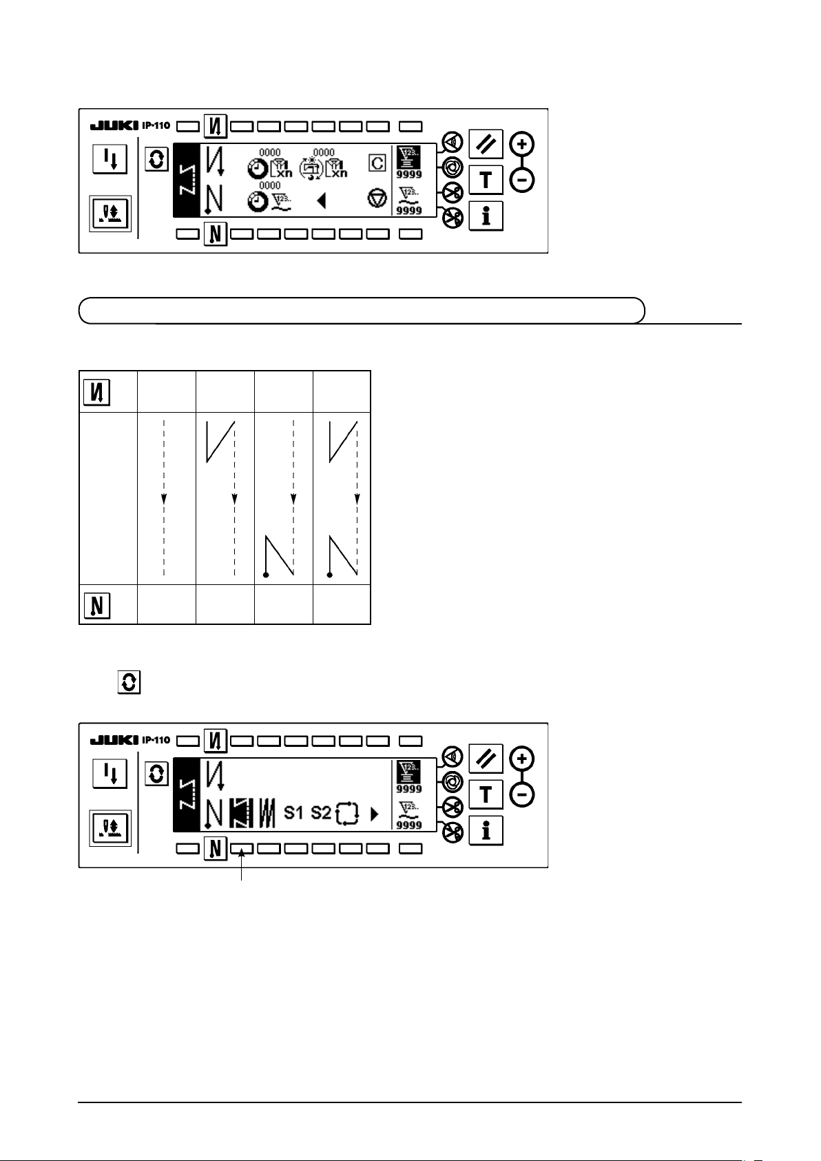
(1) Reverse stitching pattern
2
OFF ON ON
OFF
A
B
Sewing
pattern
C
D
OFF OFF
3
ON ON
Press to display the pattern list screen.
A
B
C
D
1
1) Press switch 1 to select the reverse stitching pattern, and the screen is automatically changed over to the
number of stitches of reverse stitching setting screen to display the number of stitches which has already
been set.
– 8 –
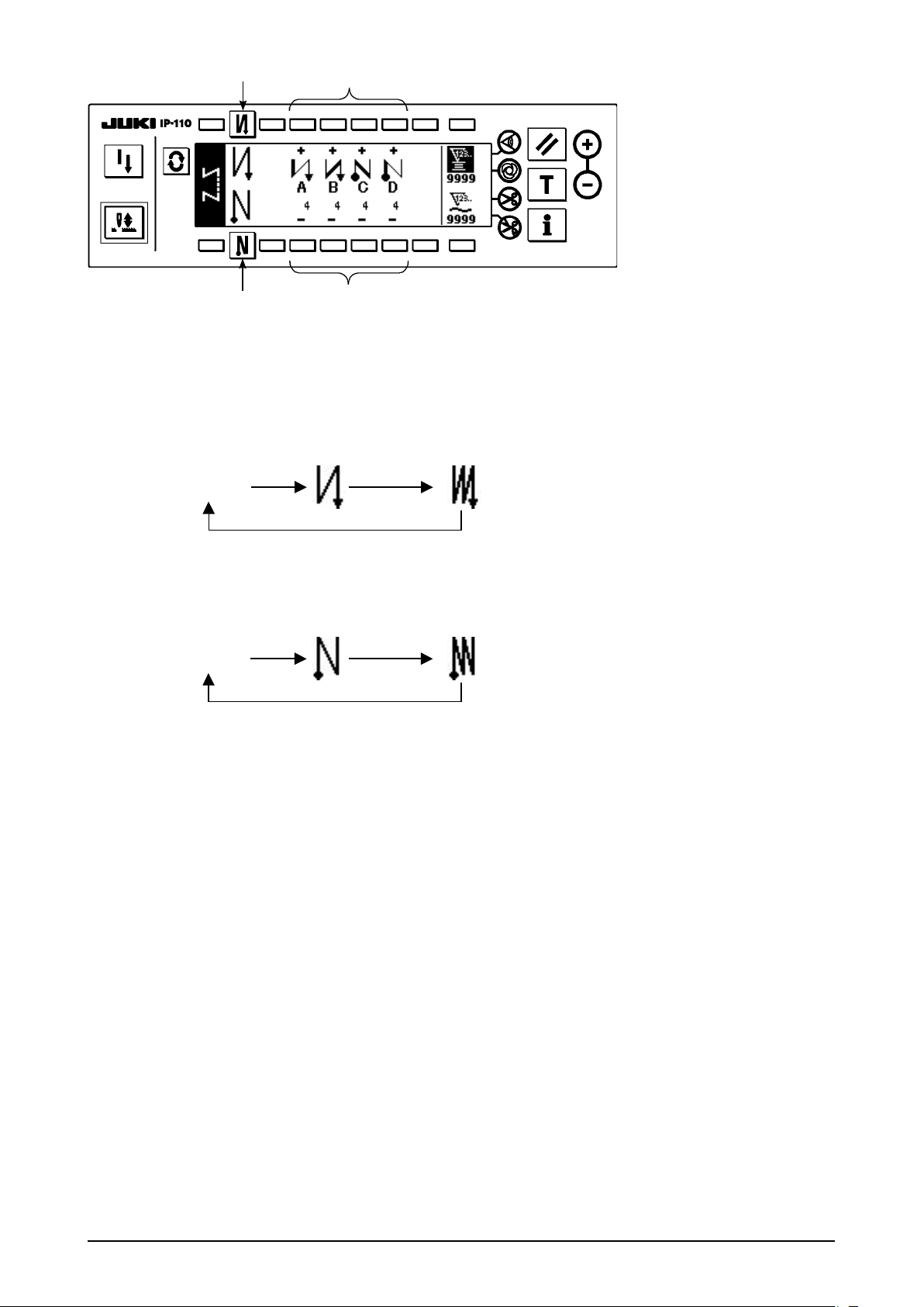
2
4
3
2) When changing the number of stitches, change it with switches 4 and 5 for setting the number of
stitches A through D.
(The range of the number of stitches that can be changed : 0 to 99 stitches)
3) Press switch 2 to set the reverse stitching at the start of sewing.
No setting Reverse stitching
at the start of sewing
4) Press switch 3 to set the reverse stitching at the end of sewing.
No setting Reverse stitching
at the end of sewing
5
Double reverse stitching
at the start of sewing
Double reverse stitching
at the end of sewing
– 9 –
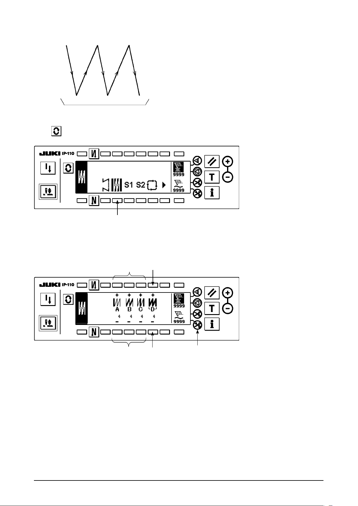
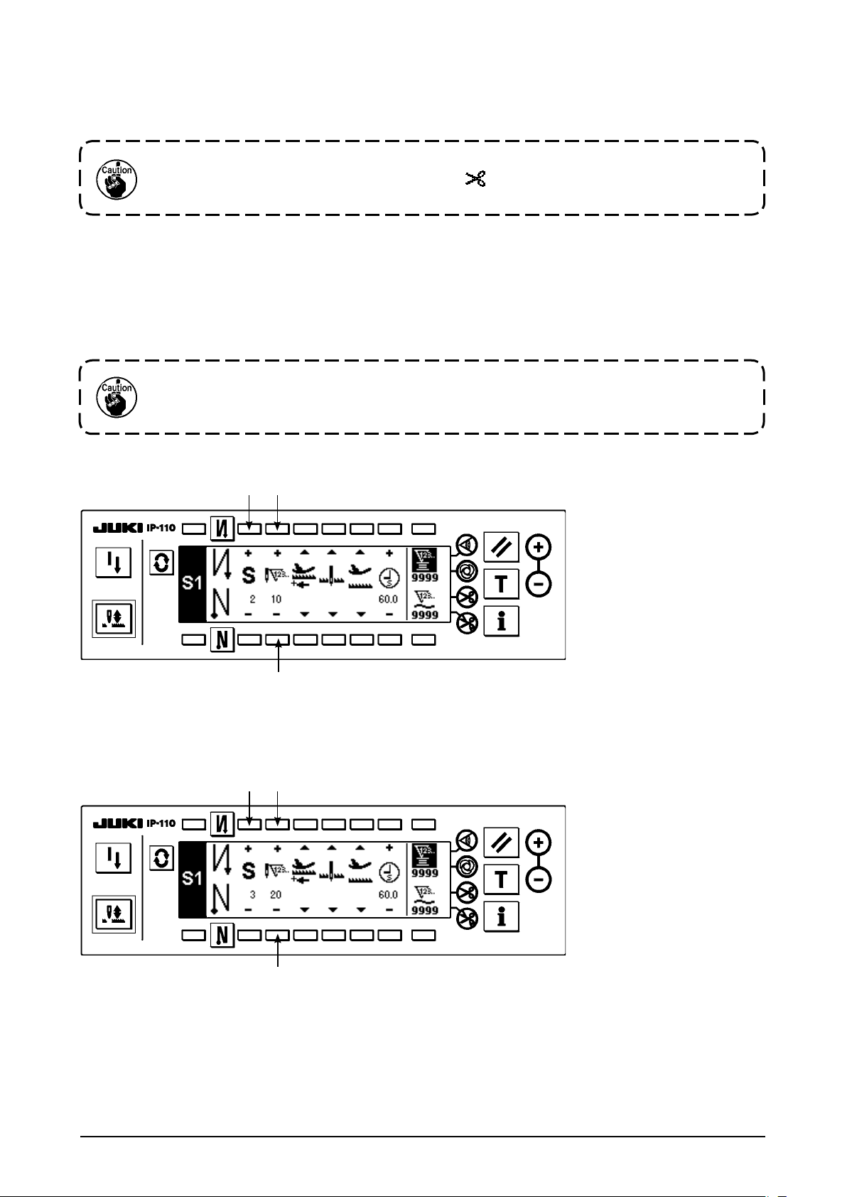
(2) Overlapped stitching pattern
A C C
B B
D
Press to display the pattern list screen.
1
1) Press switch 1 to select the overlapped stitching pattern, and the screen is automatically changed over to
the number of stitches of overlapped stitching setting screen to display the number of stitches which has
already been set.
2
3
2) When changing the number of stitches, change it with switches 2 and 3 for setting the number of
stitches for processes A through C. To change the number of times of the whole processes, change it with
switches 4 and 5 for setting the number of processes D.
(The range of the number of stitches A, B and C that can be changed : 0 to 19 stitches. The range of the
number of processes D that can be changed : 0 to 9 times)
3) Depress the front part of the pedal once, and the sewing machine will repeat the normal stitching and
reverse stitching as many as the number of specied times. Then the sewing machine will automatically
make the thread trimmer actuate and will stop to complete the overlapped stitching procedure. (The one-
shot automatic stitching cannot be turned OFF.)
4) When thread trimming prohibiting function 6 is selected, the machine will stop with the needle up upon
completion of the overlapped stitching procedure without performing thread trimming.
4
5
6
– 10 –
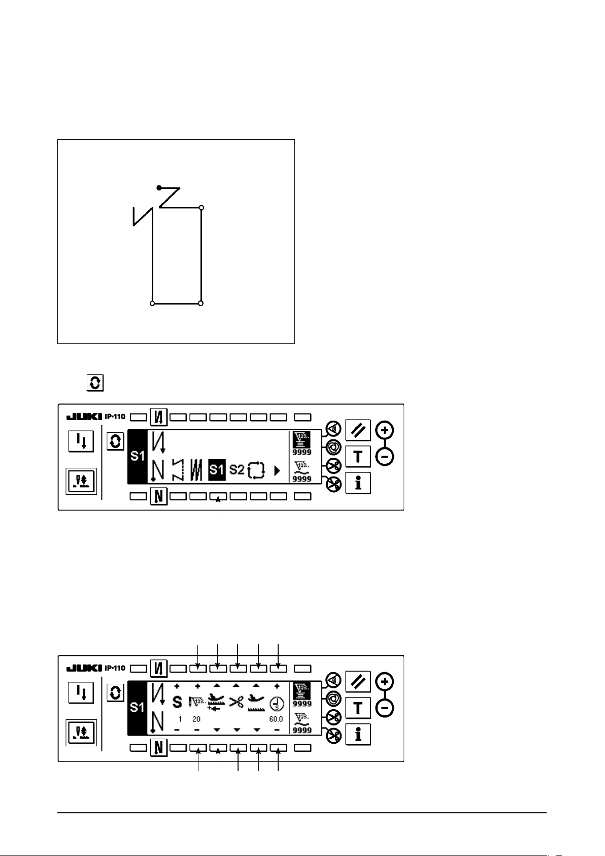
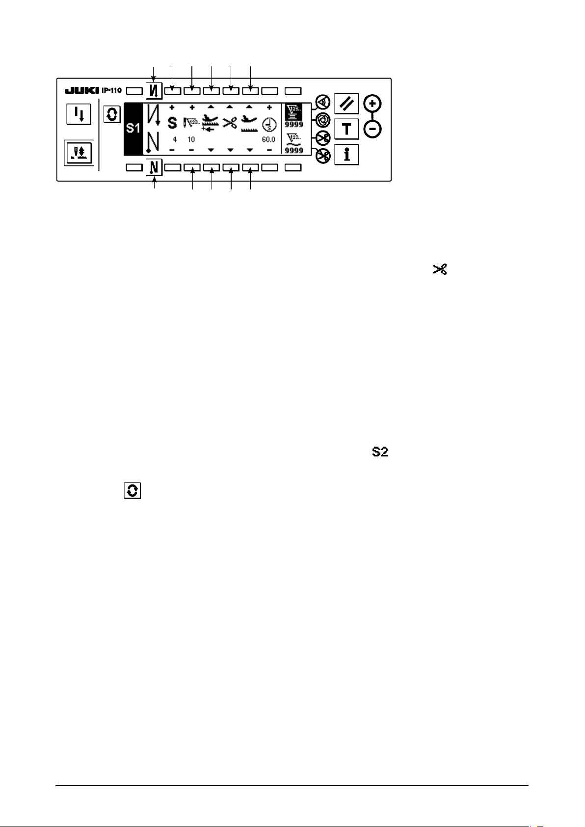
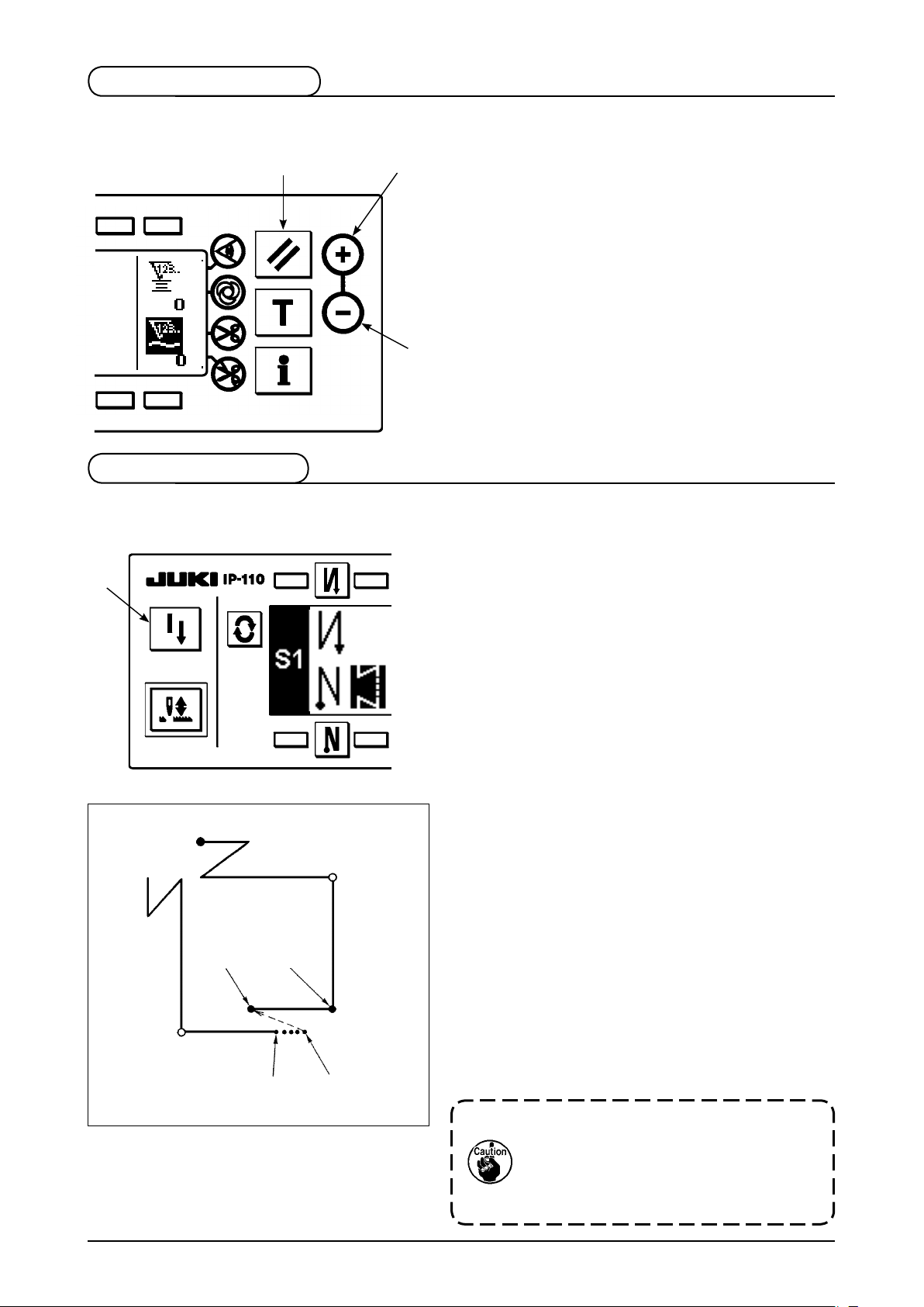
(3) Programmed stitching pattern
The constant-dimension stitching process can be programmed as many as 20 operation steps. The sewing
conditions including the number of stitches, needle up/down stop mode, automatic thread trimming,
continuous operation steps, lifting/lowering of presser foot and normal/reverse feed stitching can be
separately specified for the respective operation steps. If the lifting of presser foot is specified, the time
during which the presser foot is raised can be also specied.
Example of programmed stitching pattern
4
Step 4
4
4
4
20 20
10
Step 3Step 1
10
Step 2
Press to display the pattern list screen.
Programm ing pro cedure is described below
taking the pattern on the left side as an example.
1
1) Press switch 1 to select the programmed stitching pattern, and the screen is automatically changed over
to the programmed stitching setting screen to display the number of stitches and data on the operation
step 1 which have already been specied.
[Step 1]
2 4 6
3 5 7 9
8
!0
!1
– 11 –
1) Conrm that step 1 is displayed on the panel. Now, set the number of stitches to 20 using switches 2 and 3.
2) Set the feeding direction to the normal direction using switches 4 and 5.
3) Set the stop state of the sewing machine to the needle-down stop mode using switches 8 and 9.
If the number of stitches is set to 0 stitch or the stop-state of the sewing machine is
set to the automatic thread trimming mode
subsequent operation step.
4) Set the position of the presser foot, when the sewing machine stops, to the upper stop position using
switches 8 and 9.
(If you want to specify, In particular, the length of time during which the presser foot Is raised, set It as
desired using switches !0 and !1. In the Initial state, the length of time Is 60 seconds. Possible setting
range of the time during which the presser foot Is raised : 0.1 sec. to 99.9 sec.)
Setting with switches 8 and 9, or !0 and !1 is possible only in the state that the use of
auto lifter can be performed (FL ON). It is possible to change over FL ON / OFF by turning
ON the power while pressing UP switch of the control box.
, the machine will not proceed to the
[Step 2]
5) Press switch !2 once to display step 2.
6) Set the number of stitches to 10 using switches 2 and 3.
[Step 3]
!2
!2
2
3
2
3
7) Set the feeding direction to the normal direction, the stop-state of the sewing machine to the needle-down
stop mode and the position of the presser foot to the upper stop position as in the case of step 1.
8) Press switch !2 once to display step 3.
9) Set the number of stitches to 20 using switches 2 and 3.
10) Set the feeding direction to the normal direction, the stop state of the sewing machine to the needle-
down stop mode and the position of the presser foot to the upper stop position as in the case of steps 1
and 2.
– 12 –
[Step 4]
!3
!2
2 4 6 8
!4
11) Press switch !2 once to display step 4.
12) Set the number of stitches to 10 using switches 2 and 3.
13) Set the feeding direction to the normal direction using switches 4 and 5.
14) Set the stop state of the sewing machine to the automatic thread trimming mode
and 7.
15) Set the position of the presser foot, when the sewing machine stops, to the upper stop position using
switches 8 and 9.
16) Select the reverse stitching using switches !3 and !4. This completes the data setting procedure.
17) It is also possible to specify the double reverse stitching using switches !3 and !4.
Every time each step is nished, operate the touch-back switch, and the sewing machine runs at a low
speed (stitch compensation operation).
You can program another sewing processes in the programmed stitching pattern 2 following the
aforementioned procedure.
In case of pattern 2, the display on the left end of the screen becomes .
3 5 7 9
using switches 6
When switch is pressed in the programmed stitching setting screen, the screen is changed over to the
number of stitches of reverse stitching screen and the number of stitches of reverse stitching at the time
of programmed stitching can be set. The number of stitches of reverse stitching can be separately set for
patterns 1 and 2.
– 13 –
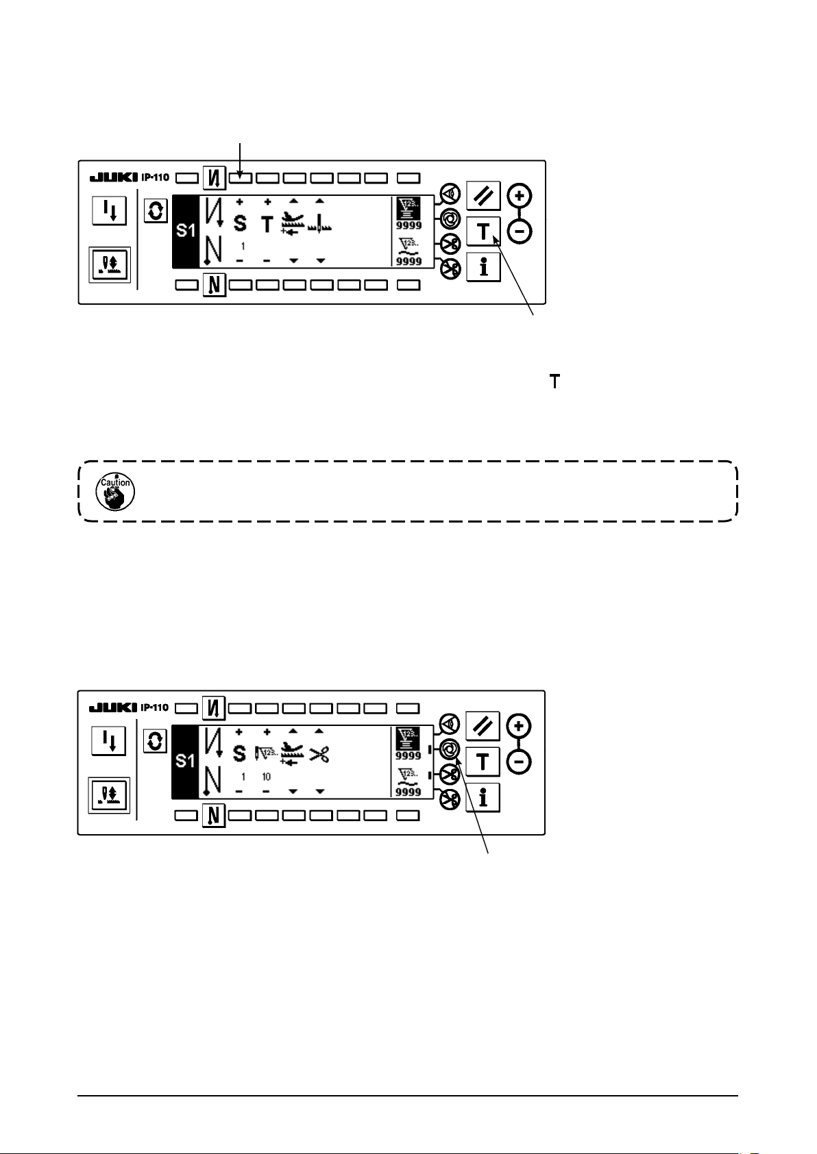
Teaching mode
<
In the teaching mode, it is possible to set the number of stitches of the step in a programmed stitching pattern
to the number of stitches that has been actually sewn.
1) In the programmed stitching setting screen, press teaching switch 1 to select the teaching mode.
2) The indication shown on the number of stitches input section changes to . This shows that the sewing
machine has entered the teaching mode.
3) Depress the front part of the pedal to make the sewing machine perform sewing until the last stitch of the
current operation step is reached.
>
2
1
The number of stitches cannot be inputted by turning the hand wheel by hand or
operating the needle up/down switch.
4) Return the pedal to its neutral position to make the sewing machine stop running. Now, the number of
stitches which has been sewn is displayed.
5) Proceed to the subsequent step using switch 2 or make the sewing machine perform thread trimming.
This completes the input of the number of stitches for operation step 1.
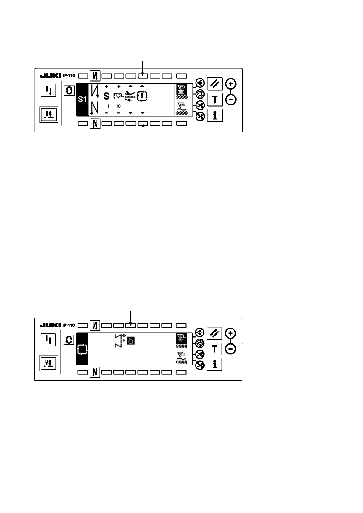
One-shot automatic stitching
<
The one-shot automatic stitching function can be separately set by steps.
>
1
1) In the programmed stitching pattern setting screen, press one-shot automatic stitching switch 1 to select
the one-shot automatic stitching function.
2) A mark is displayed on LCD section of the switch, which shows the one-shot automatic stitching function
has been selected.
3) In the step where the one-shot automatic stitching function has been selected, the sewing machine
will automatically continue sewing, once the sewing machine starts running, until the end of the step is
reached.
– 14 –
Continuous stitching mode
<
In this mode, it is possible to make the sewing machine execute the subsequent step after the completion of
the current step.
1) In the programmed stitching pattern setting screen, select the continuous stitching mode using switches
and 2.
1
2) As long as the continuous stitching mode is selected, you can make the sewing machine execute the
subsequent step set in the program after the completion of the current step by depressing the front part of
the pedal.
>
1
2
To operate the operation panel in combination with the material edge sensor
<
• When the operation panel is used in combination with the material edge sensor, the sewing process can
be completed not by the predetermined number of stitches but by the input signal of the material edge
sensor.
• Carefully read the Instruction Manual for the material edge sensor before using the sensor with the
operation panel.
>
(4) Cycle sewing pattern
Reverse stitching pattern, overlapped stitching pattern, programmed stitching pattern 1 and programmed
stitching pattern 2 can be set and sewn as desired. (As many as eight different patterns can be set.)
1
1) Press switch 1 to display the cycle sewing edit pattern setting pop-up.
– 15 –
4 6 8
2
!0 !2
5 7 9
3
Switches 2 and 3 : These switches set the reverse stitching pattern.
Switches 4 and 5 : These switches set the overlapped stitching pattern.
Switches 6 and 7 : These switches set the programmed stitching pattern 1.
Switches 8 and 9 : These switches set the programmed stitching pattern 2.
Switches !0 and !1 : These switches delete the editing step.
Switch !2 : The screen returns to the cycle sewing setting screen.
[Example of setting]
!1
2) Every time the thread trimmer actuates, the machine proceeds to the subsequent pattern which has been
selected. (The step which is being executed is shown in reverse video during execution.)
If the thread trimmer actuates before completion of a pattern, the machine will proceed
to the subsequent program.
– 16 –
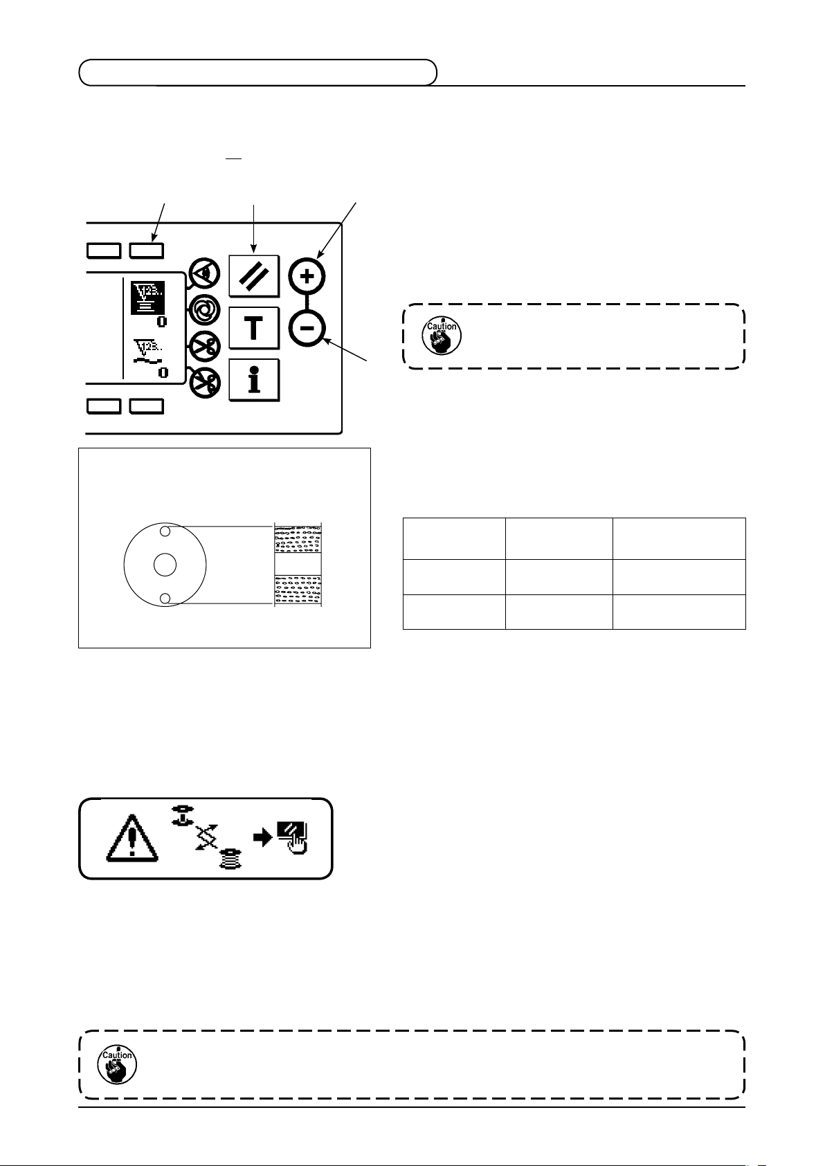
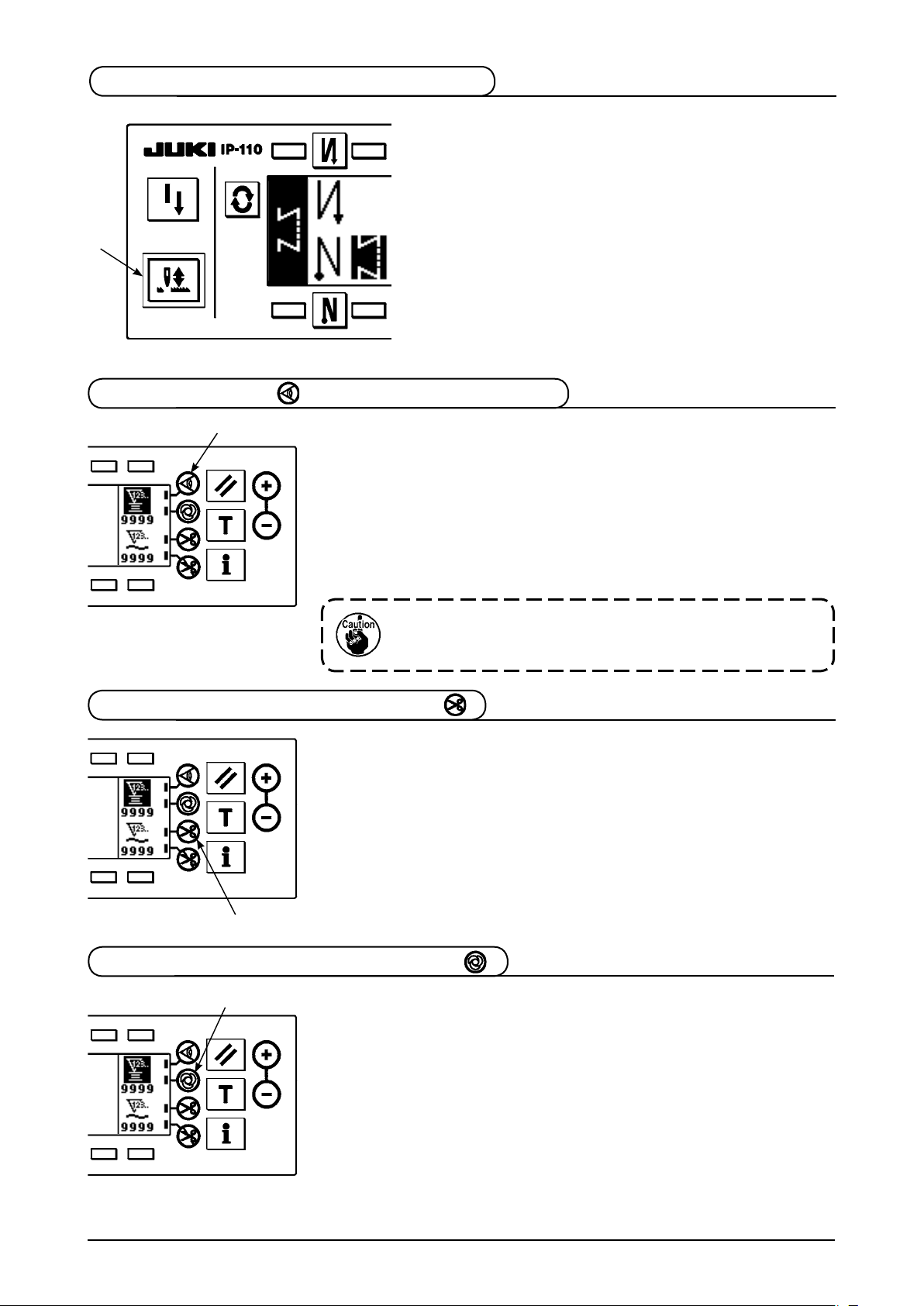
4-3. How to use the bobbin thread counter
The machine detects the number of stitches. The preset value on the bobbin thread counter is subtracted in
accordance with the number of stitches detected. (Every time the detector detects 10 stitches, 1 is subtracted
from the preset value on the bobbin thread counter.) When the value on the counter becomes a minus value
........
as (
→ 1 → 0 → –1), the buzzer (peeps three times) and the pop-up display inform that the time to
change the bobbin thread has come.
1
2
3
Initial value on the bobbin thread counter
for reference
1) Press switch 1 to select the bobbin thread counter.
Then press counter reset switch 2 to return the
value indicated on the bobbin thread counter to the
initial value (it has been factory-set to “0” at the time
of delivery).
The bobbin thread counter cannot be
reset during sewing. In this case, make
4
the thread trimmer actuate once.
2) Set an initial va l u e using counter value setting
switches 3 and 4.
The table below gives the initia l setting values for
reference when the bobbin is wound with thread to the
extent that the pinhole in the outside of the bobbin case
is reached as shown in the gure on the left side.
Thread
used
Polyester spun
thread #50
Cotton thread #50
Length of thread
wound round the
bobbin
36 m
31 m
Value on bobbin
thread counter
1200
(stitch length : 3 mm)
1000
(stitch length : 3 mm)
Thread tension rate 100 %
* Actually, the bobbin thread counter is affected by the material thickness and the sewing speed. So, adjust
the initial value of the bobbin thread counter in accordance with the operating conditions.
3) Once the initial value is specied, start the sewing machine.
4) When a minus value is shown on the counter, the buzzer peeps three times and the pop-up display
appears, replace the bobbin thread.
Bobbin thread replacement warning pop-up
5) After the bobbin thread has been properly replaced, press counter reset switch 2 to return the value on
the bobbin thread counter to the initial value. Now, re-start the sewing machine.
6) If the remaining amount of bobbin thread is excessive or the bobbin thread runs out before the bobbin
thread counter indicates a minus value, adjust the initial value appropriately using counter value setting
switches 3 and 4.
If the remaining amount of bobbin thread is excessive ..... Increase the initial value using the “+” switch.
If the remaining amount of bobbin thread is insufcient .... Decrease the initial value using “–” switch.
If the bobbin thread counter is used in combination with the bobbin thread remaining amount
detecting device, the bobbin thread counter indicates the number of times of detection of the
bobbin thread remaining amount detecting device. So, be sure to use the device after carefully
reading the Instruction Manual for the bobbin thread remaining amount detecting device.
– 17 –
4-4. No. of pcs. counter
The No. of pcs. counter counts up the number of nished products every time the machine performs thread
trimming. (0 → 1 → 2
...........
→ 9999)
2
3
The value on the No. of pcs. counter can be modied
using counter value setting switches 3 and 4. The
value on the No. of pcs. counter is res et to "0" by
pressing counter reset switch 2.
4
4-5. Re-sewing switch
The re-sewing switch is used when the bobbin thread runs out during the programmed stitching pattern
sewing steps or the like.
1) The bobbin thread runs out during the operations
1
steps for sewing.
2) Bring the pedal to its neutral position to make the
sewing machine stop. Now, depress the back part of
the pedal to make the thread trimmer actuate.
3) Turn ON re-sewing switch 1.
4) Replace the bobbin. Slightly feed the material on the
machine in the reverse direction to return the material
to the position where the sewing was interrupted to
allow the sewing machine to sew over the nished
seam in step 2. d
5) Depress the front part of the pedal until stop position
of step 2 is reached.
e
6) Turn ON re-sewing switch e again at position 1
where the sewing has been interrupted, and the next
D
C
Step 4
B
A
step will be indicated on the operation panel. Now,
you can re-start sewing of the programmed stitching
pattern.
* If th e needle thr e a d breaks or any other trouble
occurs, which is caused by re-sewing switch 1 during
the operation steps (d → e) in the free sewing
d
Step 3Step 1
e
mode, bring the pedal to its neutral position, Then
depress the back part of the pedal to actuate the
thread trimmer. Thread the machine head and slightly
feed the material in the reverse direction, and press
re-sewing switch 1. This enables the sewing machine
to continue the sewing under the free sewing mode.
Step 2
a
b c
Then operate the operation panel as described in the
aforementioned steps 5) and 6).
a
b
c
– 18 –
To return to the rst step of the programmed
stitching pattern without using re-sewing
switch 1, depress the back part of the pedal
to actuate the thread trimmer. This makes
the operation panel give the step indication 1.
Now, you can start sewing from the rst step
of the programmed stitching pattern.
4-6. Needle up/down compensation switch
Every time needle up/down compensation switch 1
is pressed, the needle goes up when it is in its lowest
position or comes down when it is in its highest position.
This compensates the stitch by a half of the predetermined
stitch length.
Note, however, that the machine does not run continuously
1
at a low speed even if you keep the switch held pressed.
Also, note that the needle up/down compensation switch is
inoperative after turning the handwheel by hand.
Thread trimming is operative only at the time of stitch
compensation after depressing the front part of the pedal
once.
4-7. ON/OFF switch of the material edge sensor
1
• When material edge sensor 1 is pressed, ON/OFF of the material edge
sensor is changed over.
• When the material edge sensor, which is optionall y avai l a b le, is
connected to the operation panel, the ON/OFF switch of the material
edge sensor becomes effective.
• If th e material edge se n s o r is specified, th e sewing machine wi l l
automatically stop running or perform thread trimming when the sensor
detects the material edge.
If the material edge sensor is used in combination with
the operation panel, carefully read the Instruction Manual
for the material edge sensor beforehand.
4-8. Automatic thread trimming switch
• When automatic thread trimming switch 1 is pressed, ON/OFF of the
automatic thread trimming is changed over.
• This switch is used to automatically actuate the thread trimmer in a
process where the sewing machine automatically stops or when the
material edge sensor is used.
(if the automatic reverse stitching (for end) is specified, the thread
trimmer will actuate after the sewing machine completes the automatic
reverse stitching (for end).)
1
4-9. One-shot automatic stitching switch
1
• When one-shot automatic stitching switch 1 is pressed, ON/OFF of the
one-shot automatic stitching is changed over.
• This switch is used, in the constant-dimension stitching mode, rectangular
stitching mode, or in the process where the material edge sensor is
specied, to make the sewing machine automatically perform sewing at
the specied speed until the end of the process is reached only by driving
the sewing machine once.
– 19 –
4-10. Thread trimming prohibition switch
• When thread trimming prohibition switch 1 is pressed, ON/OFF of the
thread trimming prohibition is changed over.
• This switch is used to temporarily make the thread trimming function
inoperative.
The other performance of sewing machine is not affected by this switch.
(If the automatic reverse stitching (for end) is specified, the sewing
machine will perform the automatic reverse stitching at the end of
sewing.)
1
• If the automatic thread trimming switch and the thread trimming
prohibition switch are both specied, the machine will not perform
thread trimming but stop with its needle up.
4-11. Key lock
• In order to prevent the specied data on the number of stitches or the processes (A, B, C and D, or step
information) from changing by mistake, the setting switch can be locked. (Even with the setting key locked,
the pattern to be sewn and the value on the bobbin thread counter can be changed.)
• For the setting procedure, refer to 4-13 Setting for functions and set function No. 17, Key lock function (key
lock is effective with setting of “1”).
– 20 –
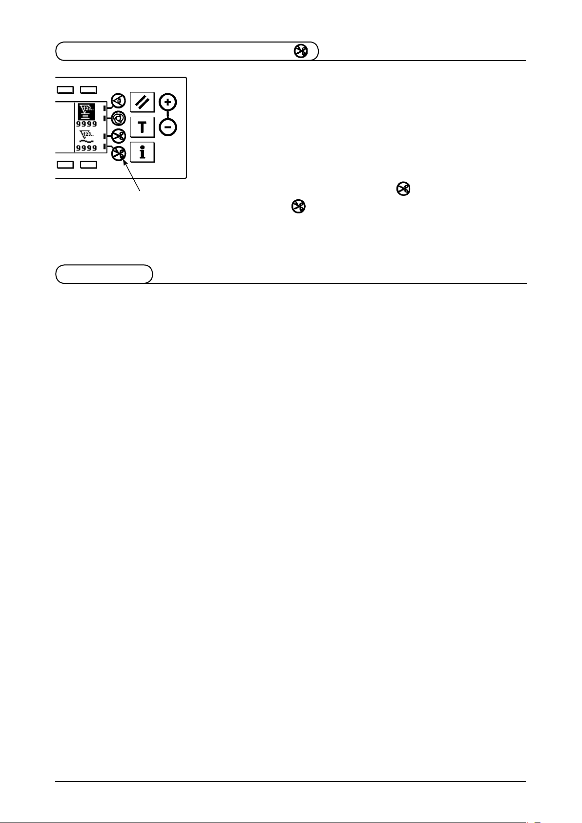
4-12. Information
Setting and checking of various data can be performed with the information.
For the information, there are the operator level and the maintenance personnel level.
Operator level
1) Turn ON the power.
2) Press switch 1 to display the information screen.
Information screen (operator level)
■
1
Sewing management information
●
For the sewing management information, there are the maintenance management function, production
control function and working measurement function.
1
: Sewing management
1
information
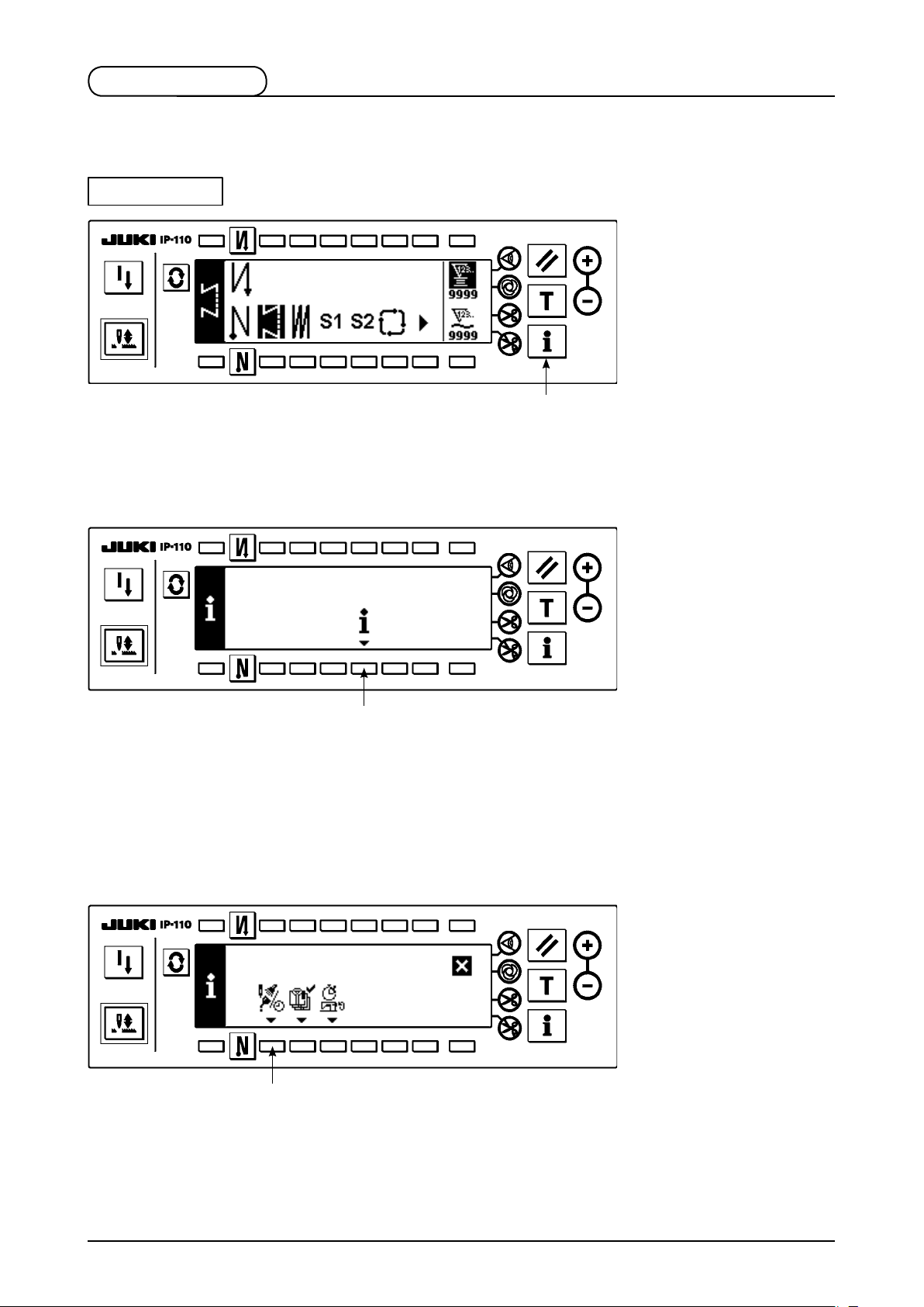
(1) Maintenance management function
1
1) Press 1 to display the maintenance function screen.
– 21 –
Maintenance function screen
■
2
4
[Explanation of the respective items]
Time of replacement of needle ......... Unit : X 1,000 stitches
2
3
4
[Explanation of the contents of display]
(Numerator / denominator)
* Number of remaining stitches up to *thousand stitches /
Time of cleaning .............................. Unit : Hour
Time of replacement of oil ................ Unit : Hour
3
Example) Replacement of needle
100 / 1600 k
Time of replacement of needle is informed every 1,600 thousand stitches.
thousand stitches
**
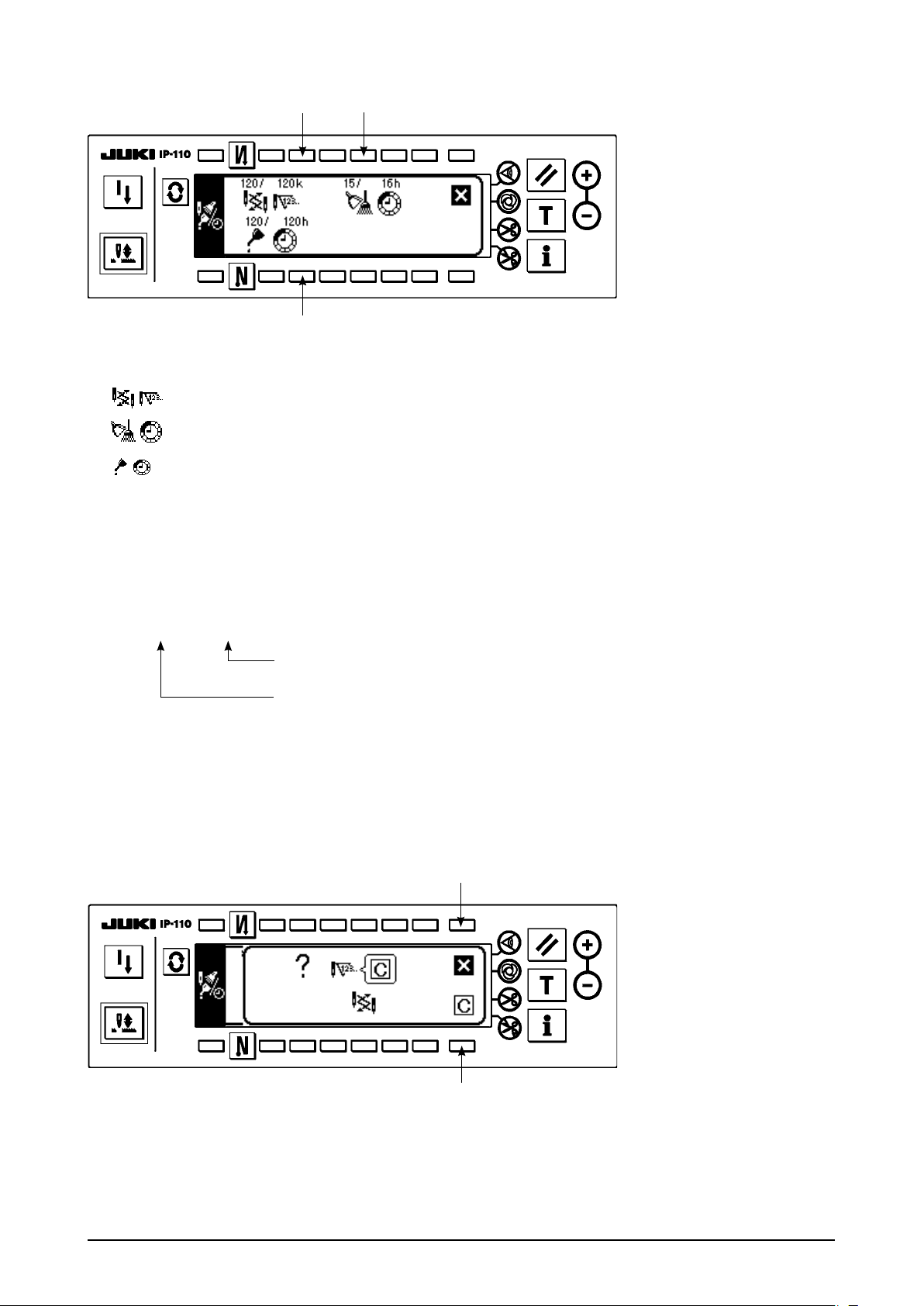
When 2, 3 and 4 switches are pressed, the clear checking screen is displayed.
Clear screen
■
: The screen returns to the maintenance function screen without performing clearing.
1
: The screen returns to the maintenance function screen after executing clearing.
2
Time of replacement of needle is informed after 100 thousand stitches.
1
2
– 22 –
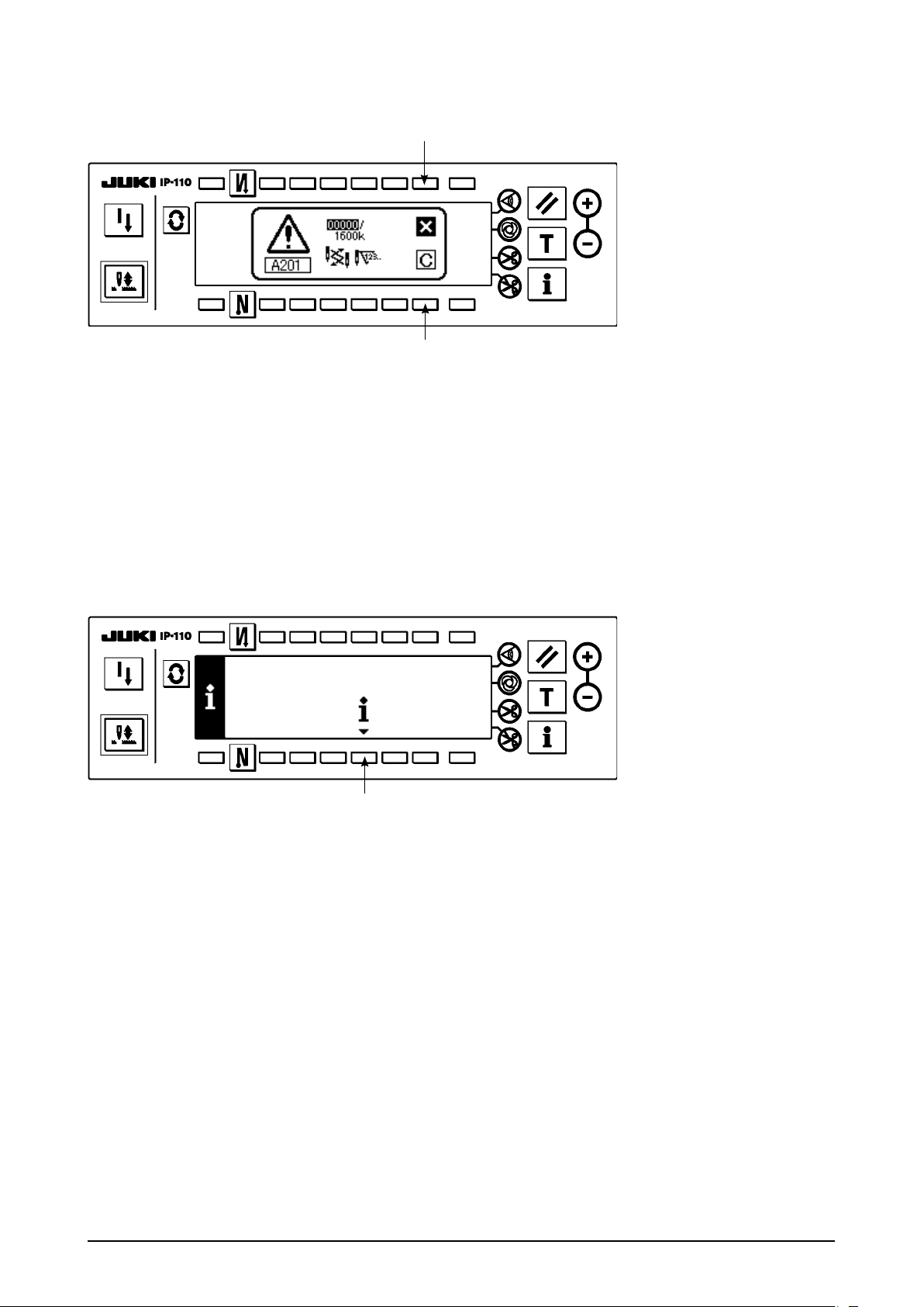
Warning screen
■
Warning screen is displayed when the warning time is reached.
1
2
: When 1 is pressed, the screen can be cleared. However, the counter itself cannot be cleared. In case
1
of the replacement of needle, the warning screen is displayed at intervals of 10 minutes until clearing
is performed. In case of other warnings, the warning screen is displayed at the time of turning ON the
power until the counter is cleared.
: When 2 is pressed, the screen is cleared and the counter value is cleared as well. From this time,
2
counting starts newly.
[Setting of the warning setting time]
Infomation screen
■
1
1) Press switch 1 for approximately three seconds in the information screen.
– 23 –

Sewing management information selection screen
■
2
2) Press 2 to display the maintenance function screen.
(For other functions, refer to the Engineer’s Manual.)
Maintenance function screen
■
3
5
3, 4, 5
6 : Number of times of thread trimming per sewing ... Unit : Number of times
■
: Inspection time (number of times of thread trimming) input screen is displayed.
Inspection time (number of times of thread trimming) input screen
4
6
7
Clear checking screen is displayed in 7. (It is not displayed when the number of times of thread trimming is
specied.)
After inputting the setting time, determine the time with 8.
In case of stopping the warning function, set the set value to “0”.
It is possible to individually set replacement of needle, cleaning, and replacement of oil
respectively.
In case of stopping all, set “0” to each.
8
– 24 –

(2) Production control function
1
1) Press 1 to display the production control screen.
Production control screen
■
2
4
[Explanation of the respective items]
Number of pcs. of current target ........... Unit : Piece
Number of pcs. of nal target ................ Unit : Piece
Current output ....................................... Unit : Piece
Time required to sew one piece (pitch time) ............ Unit : Second
This item displays that the measurement is stopped.
3
5
This item displays that the measurement is
being performed.
2) Press 2, 3, 4 and 5 to display the production control input screen.
– 25 –

Production control input screen
■
6
3) Set the respective setting items with 7. Setting time inputted in 6 is shown in reverse video.
Minimum setting possible value of pitch time is 0.50 seconds.
When 0.00 second is set, make the current target non-display.
7
7
8
4) Press 8 in the shape list screen.
Output display screen
■
9
!0
5) The output display screen is displayed. Sewing is possible with this screen.
Set value can be changed with switches 9 and !0 (Editing of the nal target value and pitch time cannot
be performed in this screen.)
The current target value and the current output can be cleared (make them “0”) with switch !1.
Setting of start/stop of the output display function can be performed with switch !2.
!1
!2
– 26 –

(3) Working measurement function
1
1) Press 1 to display the working measurement function screen.
Working measurement function screen
■
2
3
[Explanation of the respective items]
Working factor ..................................Unit : %
Working mean speed .......................Unit : rpm
Pitch time .........................................Unit : Second
Machine time ...................................Unit : Second
2) Press 3 to start the working measurement.
3) To stop the measurement, press 3 again.
4) The result of measurement can be cleared with 2.
When “Clear” is not executed, the measurement from the last time can be continued.
– 27 –

Maintenance personnel level
1
1) Turn ON the power.
2) Press switch 1 for approximately three seconds to display the information screen.
Information screen (maintenance personnel level)
■
2 3 4 5 6
Ver display ..... For the details, refer to the Engineer’s Manual.
2
Function setting ..... Refer to the item “Function setting procedure”.
3
Sewing management information
4
Communication mode ..... For the details, refer to the Engineer’s Manual.
5
Media format .... For the details, refer to Engineer's Manual.
6
When the media format is executed, all of the data that have been recorded at present
disappear. Be careful not to use it other than initialization of the media.
– 28 –

4-13. Setting for functions
(1) How to change over to the function setting mode
Do not perform switch operations other than those described in the following explanations.
Be sure to re-turn the power switch ON after one second or more has passed. If the power is
turned ON immediately after turning it OFF, the sewing machine may not work normally. In this
case, turn ON the power again.
WARNING :
To avoid possible personal injuries caused by movement other than that you desired, do not operate
the switches in the procedure other than those required, as described below, to specify the functions.
There are two kinds of function settings, Level 1 and Level 2.
Level 1 : Change of setting can be performed without turning OFF the power switch.
Level 2 : It is necessary to turn OFF the power switch after change of setting.
For the details of setting No., see P.32.
[Setting procedure of Level 2]
1) Turn ON the power. When the needle bar is not in its UP position, turn the handwheel to bring the needle
bar to its UP position.
2) Press switch 1 for
approximately three
seconds.
3
3
2
Setting No. Set value
1
3) Press switch 2 for
approximately three
seconds.
4) This screen is the function
setting screen.
Change the setting No.
with “+/–” Key of switch 3.
For the details of setting
No., see P. 32.
Example) Changing the
icker reducing
function
(Setting No. 5)
4
– 29 –
Change the setting No. to “5”
with “+” Key of switch 3 in
the gure above.
Press switch 4.
・

5
5
6
7
Change set value with
・
“+/–” Key of switch 5.
The set value has been
changed from “0” to “3”.
When this changed value
・
is acceptable, press switch
.
7
When you desire to return
the value to the previous
one, press switch 6.
[Setting procedure of Level 1]
Turn OFF the power switch
・
and turn ON the power
switch after approximately
one second.
Change of the set value
・
is determined by turning
OFF the power switch.
1) Press switch 1 for
approximately three
seconds.
1
2
2) Press switch 2.
– 30 –

3
3) This screen is the function
setting screen.
Change the setting No.
with “+/–” Key of switch
.
3
For the details of setting
No., see P. 32.
3
Setting No.
4
5
Set value
Example) Changing
the number
of rotation
of reverse
feed stitching
(Setting No. 8)
Change the setting No. to “8”
with “+” Key of switch 3 in
the gure above.
Press switch 4.
・
Change the set value with
・
“+/–” Key of switch 5.
5
6
7
Set value has been
・
changed from 1350 to
1250.
When this changed value
・
is acceptable, press switch
.
7
Press switch 6 when you
desire to return the value
to the former one.
Press switch 8 in case of
・
sewing.
– 31 –
8

(2) Function setting list
For the details of the items, refer to the Instruction Manual for SC-910.
* DDL-8700 is given as an example here. However, initial value changes according to the machine head to be
connected.
3000
Panel display
Standard set
value
N-SOFT
1
T-ACC
0
SCBOB
1
RATIO
0
S-BT
1500
NPS
0
SOUND
1
SW2
0
ASCNT
0
NTO
1
BTDS
1
KEYLOCK
0
No. Item Description
1 Soft start function The number of stitches to be sewn at a low speed when the soft-
start function is used at the start of sewing.
0 : Soft-start function is not operative.
5 Flicker reducing
function
6 Bobbin thread
counting function
7 Bobbin thread
count unit
8 Number of
rotation of reverse
feed stitching
10 Setting of needle
bar stop position
when the sewing
machine stops.
11 Click sound of key
switch mounted
on PSC
12 Optinal switch
function selection
13 Function of
prohibiting start
of the sewing
machine by
bobbin thread
counter
14 Sewing counter Counting function of sewing (number of completion of process)
15 Number of times
of detection of
run-out of bobbin
thread remaining
amount
17 Key lock function Key lock function
Flicker reducing function (If the hand lamp ickers).
0 : Flicker reducing function is not operative.
1 : Less effective
Bobbin thread counting function
0 : Bobbin thread counting function is not operative.
1 : Bobbin thread counting function is operative.
Unit of bobbin thread counting down
0 : Count/10 stitches
1 : Count/15 stitches
2 : Count/20 stitches
Sewing speed of reverse feed stitching
Position of needle bar is specied when the sewing machine stops.
0 : Predetermined lowest position
1 : Predetermined highest position
Click sound of key switch mounted on PSC is specied.
0 : Click is not operative.
1 : Click is operative.
Switching of function of optional switch.
0 : No function
1 : Needle up/down compensating stitching
2 : Back compensating stitching
3 : Function of canceling once reverse feed stitching at the
end of sewing
4 : Thread trimming function
5 : Presser foot lifting function
6 : One stitch compensating stitching
7 : Function of simultaneously canceling reverse feed
stitching at the start and end of sewing
8 : Function of neutral presser foot lifting changeover
Function of prohibiting start of the sewing machine by bobbin
thread counting
0 : When counting is out (-1 or less) Function of prohibiting
start of the sewing machine is not operative.
1 : When counting is out (-1 or less) Function of prohibiting
start of the sewing machine after thread trimming is operative.
2 : When counting is out (-1 or less), the sewing machine
stops once. Function of prohibiting start of the sewing
machine after thread trimming is operative.
0 : Sewing counter function is not operative.
1 : Sewing counter function is operative.
Number of times of detection of run-out of bobbin thread remaining
amount
0 :
1 to 19 : Number of times during which the signal is not made even
if run-out of bobbin thread remaining amount is detected.
0 : Without key lock
1 : With key lock
Function of bobbin thread remaining amount is not operative.
8 : Highly effective
/
Setting
level
1 0 to 9
2 0 to 8
1 0 to 1
1 0 to 2
1
2 0 to 1
2 0 to 1
2 0 to 8
2 0 to 2
2 0 to 1
2 0 to 19
2 0 to 1
Setting
range
150 to
– 32 –

No. Item Description
18 Bird’s nest preven-
tion function
19 Needle thread
release function at
the sewing start
20 Number of
condensation
stitches
21 Function of neutral
presser lifting
22 Function of
changeover of
compensating switch
on the operation
panel function
24 Function of ne
adjustment of
number of rotation
25 Thread trimming
motion condition
26 Function of setting
the holding force
after stop
27 Function of setting
the reaction force at
the time of retry
28 Number of stitches
of needle thread
release
29 Back solenoid initial
motion suction time
30 Function of reverse
feed stitching on the
way
31 Number of stitches
of reverse feed
stitching on the way
32 Effective condition
of reverse feed
stitching on the way
when the sewing
machine is stopping.
33 Thread trimming
function by reverse
feed stitching on the
way
This function is effective in combination with the machine head
with bird's nest prevention function (optional unit A is necessary).
0 : Bird's nest prevention function is not operative.
1 : Bird's nest prevention function is operative.
2 :
Bird's nest prevention function is operative (with thread release).
This function is effective in combination with the machine head
with bird's nest prevention function (optional unit A is necessary).
0 : Needle thread release function is not operative.
1 : Needle thread release function is operative.
This function is effective in combination with the machine head
with bird's nest prevention function (optional unit A is necessary).
0 : Condensation function is not operative.
1 to 9 : Number of condensation stitches
Function of lifting presser foot when the pedal is in neutral position.
0 :
Function of neutral automatic presser lifting is not operative.
1 : Selection of function of neutral presser lifting.
Function of needle up/down compensating switch on the operation panel can be changed.
0 : Needle up/down compensation
1 : One stitch compensation
Number of rotation can be compensated.
Be sure to normally use this function with "0". 2
This function sets the thread trimming motion after DOWN position has been off by turning handwheel by hand.
0 :
Thread trimming after turning handwheel by hand is permitted.
1 : Thread trimming after turning handwheel by hand is
prohibited.
This function prevents the sewing machine from the reverse rotation after it has stopped.
0 : Initial value
1 : Less effective / 9 : Highly effective
This function sets the magnitude of return force of the needle
bar before the retry motion.
1 : Less return force / 100 : High return force
This function is effective in combination with the machine head
with bird's nest prevention function (optional unit A is necessary).
This function sets the number of stitches grasping thread at the
sewing start.
0 to 30 stitches
This function sets the suction time of initial motion of back-tack
solenoid.
50 ms to 300 ms
Function of reverse feed stitching on the way
0 : Function of reverse stitching on the way is not operative.
1 : Function of reverse feed stitching on the way is operative.
Number of stitches of reverse feed stitching on the way.
Effective condition of reverse feed stitching on the way
0 : Function is not operative when the sewing machine stops.
1 : Function is operative when the sewing machine stops. 2 0 to 1
Thread trimming function by reverse feed stitching on the way
0 : Automatic thread trimming function after completion
of reverse feed stitching on the way is not operative.
1 : Automatic thread trimming after completion of
reverse feed stitching on the way is performed.
Setting
level
2 0 to 2
2 0 to 1
1 0 to 9
1 0 to 1
2 0 to 1
2 0 to 1
2 0 to 9
2
1 0 to 30
2
2 0 to 1
2 0 to 19
2 0 to 1
Setting
range
–15 to
15
1 to
100
50 to
300
Panel display
Standard set
value
BNC
0
THOLD
0
N-CS
0
N-NPL
0
F-CMSP
0
F-FAS
0
F-TRMC
1
F-RTPC
0
F-RTRC
50
F-UTHR
1
T-RSS
250
OBT
0
N-OBT
4
OBTS
0
OBTT
0
– 33 –

No. Item Description
35 Number of rotation at
a low speed
36 Number of rotation of
thread trimming
37 Number of rotation of
soft-start
38 One-shot speed One-shot speed (The max. value depends on the number of
39 Pedal stroke at the
start of rotation
40 Low speed section of
pedal
41 Starting position of
lifting presser foot by
pedal
42 Starting position of
lowering presser foot
43 Pedal stroke 2 for
starting thread
trimming
44 Pedal stroke for
reaching the maximum
number of rotation
45 Compensation of
neutral point of the
pedal
46 Auto-lifter selecting
function
47 Auto-lifter selecting
function
48 Pedal stroke 1 for
starting thread
trimming
49 Lowering time of
presser foot
51 Compensation of
solenoid-on timing of
reverse feed stitching
at the start of sewing
52 Compensation of
solenoid-off timing of
reverse feed stitching
at the start of sewing
53 Compensation of
solenoid-off timing of
reverse feed stitching
at the end of sewing
55 Foot lift after thread
trimming
Lowest speed by pedal
Thread trimming speed
(Caution) Do not change the set value. When it is changed,
the sewing machine may be damaged.
Sewing speed at the start of sewing (soft-start)
rotation of the sewing machine head.)
Position where the sewing machine starts rotating from pedal
neutral position (Pedal stroke)
Position where the sewing machine starts accelerating from
pedal neutral position (Pedal stroke)
Position where the cloth presser starts lifting from pedal neutral position (Pedal stroke) 2
Starting position of lowering presser foot
Stroke from the neutral position
Position 2 where the thread trimming starts from pedal neutral
position(When the function of lifting presser foot by pedal is
provided.) (Pedal stroke)
Position where the sewing machine reaches its highest sewing
speed from pedal neutral position (Pedal stroke) 2
Compensation value of the pedal sensor
Auto-lifter selection
0 : Solenoid drive system
1 : Pneumatic drive system
Limitation time of waiting for lifting solenoid type auto-lifter
device
Position where thread trimming starts from pedal neutral
position (Standard pedal) (Pedal stroke) 2
Lowering time of presser foot after the pedal has been
depressed.
(Start of rotation of the sewing machine is delayed during this
time.)
Compensation of starting the solenoid for reverse feed stitching when reverse feed stitching at the start of sewing is performed.
Compen sation of releasin g the solenoid for reve rse feed
stitching when reverse feed stitching at the start of sewing is
performed.
Compen sation of releasin g the solenoid for reve rse feed
stitching when reverse feed stitching at the end of sewing is
performed.
Function of lifting presser foot at the time of (after) thread
trimming
0 : Not provided with the function of lifting presser foot
after thread trimming
1 : Provided with the function of lifting presser foot
automatically after thread trimming
Setting
level
1
2
1
1
2
2
2 8 to 50
2
2
2 0 to 1
2
2
1
1
1
2 0 to 1
Setting
range
20 to
400
20 to
250
150 to
5500
200 to
Max
10 to
50
10 to
100
– 60 to
– 10
– 60 to
– 10
10 to
150
– 15 to
15
10 to
600
– 60 to
– 10
0 to
250
– 36 to
36
– 36 to
36
– 36 to
36
Panel display
Standard set
value
S-POS
200
S-TRM
210
S-SOFT
800
S-ASS
2000
P-SSP
30
P-LSA
60
P-FLW
– 21
P-FLD
10
P-TRM2
– 51
P-MAX
150
P-ANP
0
FLSEL
0
T-FL
60
P-TRM1
– 35
T-FLWT
140
T-SON
10
T-SOFF
16
T-EOFF
18
FLAT
1
– 34 –

No. Item Description
56 Reverse revolution
to lift the needle after
thread trimming
57 Bobbin thread
remaining amount
detection function
58 Function of holding
predetermined upper/
lower position of the
needle bar
59 Function of Auto/
Manual changeover of reverse feed
stitching at the start of
sewing
60 Function of stop
immediately after
reverse feed stitching
at the start of sewing
61 Function of starting
prohibition of the
sewing machine by
detection of bobbin
thread remaining
amount
64 Change-over speed of
condensation stitch or
EBT (end back tack)
65 On-timing of solenoid
for condensation stitch
(when condensation
stitch is performed by
1 stitch.)
66 On-timing of solenoid
for condensation stitch
(when condensation
stitch is performed by
2 stitches.)
67 Presser foot lifting
solenoid output duty
setting
70 Function of soft-down
of presser foot
71 Function of limitation
of re-acceleration from
reduction of speed
Function of reverse revolution to lift the needle at the time of
(after) thread trimming
0 : Not provided with the function of reverse revolution to
lift the needle after thread trimming
1 : Provided with the function of reverse revolution to lift
the needle after thread trimming
Function of detecting bobbin thread remaining amount at the
time of (after thread trimming
0 : Not provided with the function of detecting bobbin
thread remaining amount
1 : Provided with the function of detecting bobbin thread
remaining amount
unction of holding predetermined upper/lower position of the
needle bar
0 : Not provided with the function of holding predetermined
upper/lower position of the needle bar
1 : Provided with the function of holding predetermined
upper/lower position of the needle bar
This function can specify the sewing speed of reverse feed
stitching at the start of sewing.
0 : The speed will depend on the manual operation by
pedal, etc.
1 : The speed will depend on the specied reverse feed
stitching speed (No. 8).
Function at the time of completion of reverse feed stitching at
the start of sewing
0 : Not provided with the function of temporary stop of
the sewing machine at the time of completion of
reverse feed stitching at the start of sewing.
1 : Provided with the function of temporary stop of the
sewing machine at the time of completion of reverse
feed stitching at the start of sewing.
Function of starting prohibition of the sewing machine by detection of bobbin thread remaining amount
0 : This function does not stop the sewing machine when
counting is out (-1 or less).
1 : This function stops the sewing machine when
counting is out (-1 or less).
Initial speed when starting condensation stitch or EBT
Starting (compensation) timing of solenoid for compensation
stitch : -1
Compensation value of starting the solenoid when condensation stitch is performed by 1 stitch.
Starting (compensation) timing of solenoid for condensation
stitch : -2
Compensation value of starting the solenoid when condensation stitch is performed by 2 stitches.
Duty of presser foot lifting solenoid output [%]
Presser foot is slowly lowered.
0 : Presser foot is rapidly lowered.
1 : Presser foot is slowly lowered.
Speed limitation is performed at the time of re-acceleration on
the way of reducing speed of the sewing machine.
It is effective when operating inching sewing.
Setting
level
2 0 to 1
2 0 to 1
2 0 to 1
2 0 to 1
2 0 to 1
2 0 to 1
2
2
2
2 5 to 40
2 0 to 1
2 0 to 5
Setting
range
0 to
250
– 36 to
– 36 to
Panel display
Standard set
value
0
0
RATRM
0
BTDF
0
HPOS
0
SBTO
1
SBTQ
0
ASBOB
1
S-WAIT
180
T-CS1
– 15
T-CS2
– 15
FLDTY
20
F-SDFL
0
F-ACRA
0
– 35 –

No. Item Description
72 Function of limitation
of acceleration at the
start of rotation
Speed limitation is performed at the time of start-up of the
sewing machine (excluding the start of sewing).
It is effective when operating inching sewing.
73 Retry function This function is used when needle cannot pierce materials.
0 : Normal
1 : Retry function is provided.
75 Rotating direction of
motor
Normal rotating direction of motor
0 : Clockwise
1 : Counterclockwise
76 Function to select the
start-up speed of the
sewing machine
84 Initial motion suction
Starting curve of the sewing machine is selected.
0 : Normal curve
1 : More sharp curve
Suction motion time of presser foot lifting solenoid
time of presser foot
lifting solenoid
87 Function of pedal
curve selection
89 Tension release
Pedal curve is selected. (Improving pedal inching operation)
2
Number of rotations
0
1
Pedal stroke
Unused
function
91 Function of prohibiting
compensation
operation after turning
handwheel by hand
92 Function of reducing
speed of reverse feed
stitching at the start of
sewing
93 Function added to
needle up/down
compensating switch
94 Continuous stitching
+ one-shot stitching
non-stop function
It is effective in combination with the machine head provided
with tension release function.
0 : Tension release function is ineffective.
1 : Tension release function is effective.
Function to reduce speed at the time of completion of reverse
feed stitching at the start of sewing.
0 : Speed is not reduced.
1 : Speed is reduced.
Function to reduce speed at the time of completion of reverse
feed stitching at the start of sewing.
0 : Speed is not reduced.
1 : Speed is reduced. (Upper stop
upper stop)
→
In IP-110 program functions, a function that does not stop the
sewing machine by combining continuous stitching with one-
shot stitching when the step is changed.
0 : Normal (The sewing machine stops when a step is
completed.)
1 : The sewing machine does not stop when a step is
completed and proceeds to next step.
96 Max. number of
rotation setting
Max. number of rotation of the sewing machine head can be
set.
* Setting differs according to the resistor pack to be connected.
101 Sewing counter input
function
This function selects the input destination of the sewing
counter.
0 : Every time thread trimming is performed, the counter
automatically counts up.
1 : The counter counts up by inputting of the external
sewing counter SW
Setting
level
1 0 to 5
1 0 to 1
2 0 to 1
2 0 to 1
2
2 0 to 2
2 0 to 1
2 0 to 1
2 0 to 1
2 0 to 1
2 0 to 1
2
2 0 to 1
Setting
range
40 to
300
50 to
Max
Panel display
Standard set
value
F-ACR
0
F-RET
1
DM
0
F-SCS
0
T-PUT
100
F-PCS
0
TRS
0
F-PMAT
1
F-DSBT
0
F-MADF
0
F-SBTC
0
S-MAX
4000
F-MAC
0
– 36 –

5. PANEL FOR LH-4168/4188
5-1. Basic screen
WELCOME screen is displayed immediately after turning ON the power.
The screen immediately after WELCOME screen becomes the screen that performs the sewing pattern
setting that was selected when turning OFF the power previously.
Every time switch is pressed, the screen changes.
Pattern list screen
■
Selection of the respective shapes is performed.
Corner pattern selection pop-up
■
Corner pattern No. is selected.
Step pattern selection pop-up
■
Step pattern No. is selected.
– 37 –

– 38 –
Number of stitches of back tuck stitching setting screen
■
Setting of number of stitches of reverse stitching is performed.
<When reverse stitching pattern is selected>
<When corner pattern is selected>
<When step pattern is selected>
Number of stitches of overlapped stitching setting screen
■
Setting of number of stitches of overlapped stitching is performed.

Corner pattern setting screen
■
Setting of the corner pattern is displayed.
Step edit screen
■
Contents of the step are set.
Corner edit screen
■
Contents of the corner are set.
Step pattern setting screen
■
Setting of the respective conditions of the step pattern is performed.
– 39 –

– 40 –
Cycle sewing setting screen
■
Setting of the step of cycle sewing is performed.
Cycle sewing step setting pop-up
■
Setting of the step of cycle sewing is performed.
Cycle sewing step No. selection pop-up
■
Setting of the corner pattern and the step cycle sewing is performed.
Output display screen
■
Final target set value, current target value and actual results up to now are displayed.

5-2. How to operate the operation panel for sewing stitching patterns
(1) Reverse stitching pattern
2
OFF ON ON
OFF
A
B
Sewing
pattern
C
D
3
OFF OFF
ON ON
Press to display the pattern list screen.
A
B
C
D
1
1) Press switch 1 to select the reverse stitching pattern, and the screen is automatically changed over to the
number of stitches of reverse stitching setting screen to display the number of stitches which has already
been set.
– 41 –

– 42 –
2
4
3
2) When changing the number of stitches, change it with switches 4 and 5 for setting the number of
stitches A through D.
(The range of the number of stitches that can be changed : 0 to 99 stitches)
3) Press switch 2 to set the reverse stitching at the start of sewing.
No setting Reverse stitching
at the start of sewing
4) Press switch 3 to set the reverse stitching at the end of sewing.
No setting Reverse stitching
at the end of sewing
5
Double reverse stitching
at the start of sewing
Double reverse stitching
at the end of sewing

(2) Overlapped stitching pattern
A
C
B
Press to display the pattern list screen.
B
D
C
1
1) Press switch 1 to select the overlapped stitching pattern, and the screen is automatically changed over to
the number of stitches of overlapped stitching setting screen to display the number of stitches which has
already been set.
2
3
2) When changing the number of stitches, change it with switches 2 and 3 for setting the number of
stitches for processes A through C. To change the number of times of the whole processes, change it with
switches 4 and 5 for setting the number of processes D.
(The range of the number of stitches A, B and C that can be changed : 0 to 19 stitches. The range of the
number of processes D that can be changed : 0 to 9 times)
3) Depress the front part of the pedal once, and the sewing machine will repeat the normal stitching and
reverse stitching as many as the number of specied times. Then the sewing machine will automatically
make the thread trimmer actuate and will stop to complete the overlapped stitching procedure. (The oneshot automatic stitching cannot be turned OFF.)
4) When thread trimming prohibiting function 6 is selected, the machine will stop with the needle up upon
completion of the overlapped stitching procedure without performing thread trimming.
4
5
6
– 43 –

– 44 –
(3) Corner pattern
The corner stitching process can be programmed as many as 8 processes (as many as 16 processes when
repeating is effective) in advance. The needle bar to be stopped and the number of stitches of sewing with
single needle can be specied in advance for the respective processes.
Press switch to display the pattern list screen.
1
1) Press switch 1 to display the corner pattern No. selection pop-up.
2
2) When switches 2 are pressed and the corner pattern No. is selected, the screen is automatically changed
over to the corner pattern setting screen to display the state of the pattern which has been already
specied.

3) The table below shows the initial setting of each pattern.
Pattern
No.
1
2
3 to 8
Indication
Corner type of the corner
stitching processes
A
G / A
/
/
/
/
C
F
A
/
/
/
/
C
F
/
C
/
C
/
/
Example of sewing
Attaching pocket on jeans or
the like
Sewing collars
of ja c ket s o r
the like
– 45 –

– 46 –
4) The table below shows the initial setting of each corner type.
Corner
type
A
B
C
Indicating
section
Needle bar to be
stopped and the
number of stitches
Left-hand needle bar
Inside corner
1 stitch
Outside corner
1 stitch
Right-hand needle bar
Inside corner
1 stitch
Outside corner
1 stitch
Left-hand needle bar
Inside corner
2 stitch
Outside corner
2 stitch
Example of sewing
Corner
type
F
G
H
Indicating
section
Needle bar to be
stopped and the
number of stitches
Right-hand needle bar
Inside corner
3 stitch
Outside corner
3 stitch
Left-hand needle bar
Inside corner
1 stitch
Outside corner
0 stitch
Right-hand needle bar
Inside corner
1 stitch
Outside corner
0 stitch
Example of sewing
Left-hand nee-
D
E
Right-hand needle bar
Inside corner
2 stitch
Outside corner
2 stitch
Left-hand needle bar
Inside corner
3 stitch
Outside corner
3 stitch
L
R
dle bar
Inside
corner
Outside
corner
Number of stitches
is determined by
operating the pedal.
Right-hand needle bar
Inside
corner
Outside
corner
Number of stitches
is determined by
operating the pedal.

5) Modication of the pattern
[To add the step]
1. When adding the step, press the switch to which nothing is registered (example in the illustration is
SW 1).
1
2. Corner type which is used in the step and the kind of return are selected in the step edit pop-up.
1
2
and 2 : These switches select the corner type.
1
and 4 : These switches select the kind of return.
3
: Change is determined and the screen returns to the step setting screen.
5
There are 4 kinds of returns in total.
: Return is performed after executing the selected corner step.
: Return is not performed.
: It is the step on the way of return. It cannot be selected in the last step.
: 2-needle sewing is performed after executing the selected corner, and return is performed.
3
4 5
When or is selected in the kinds of returns, the step after it is deleted.
– 47 –

– 48 –
[To change the step]
1. In order to edit the step which has been already registered, press the switch of the step you desire to
edit.
(Example in the illustration is switch of 1)
1
Setting procedure is the same as that of adding the step.
[To delete the step]
1. When deleting the step, press the switch 1 of step which is one before the process you desire to
delete.
(As an example, select the step in which "B" exists to delete after "C".)
1

2. Set the kind of return to or with switch 2 in the step pop-up screen.
Even when or is selected on the way of return, it is not reected.
3. Step after the set step is deleted. (Screen is the case where is set in the kinds of returns.)
6) Edit of the corner
Contents of the corners A to H are edited.
Press switch 1 to display the corner edit pop-up.
1
1 3 5
2
4 6 8
and 2 : These switches change the corner type of the object to be edited.
1
and 4 : These switches select the needle bar to be stopped for inside corner.
3
and 6 : These switches set the number of stitches for inside corner.
5
and 8 : These switches select the needle bar to be stopped for outside corner.
7
and !0 : These switches set the number of stitches for outside corner.
9
: This switch stores the data of all corners which have been edited, and the screen returns to
!1
the step setting screen.
7 9
!0
!1
Edit of corner L and corner R cannot be performed.
– 49 –

– 50 –
(4) Step pattern
The constant-dimension stitching process can be programmed as many as 20 operation steps. The sewing
conditions including the number of stitches, needle bar to be stopped, up/down stop mode, automatic
thread trimming, continuous steps, lifting/lowering of presser foot and normal/reverse feed stitching can be
separately specied for the respective operation steps.
Programming procedure is described below taking
the pattern on the left side as an example.
Step 10
Step 9
Step 8
Step 7
Step 6
Step 5
Step 4
Press to display the pattern list screen.
Step 1
Step 2
Step 3
1
1) Press switch 1 to display the step pattern No. selection pop-up.
2
2) When switches 2 are pressed and step pattern No. is selected, the screen is automatically changed
over to the step pattern setting screen to display the state of the pattern which has been already
specied.

[Step 1]
Conrm that step 1 is displayed on the panel. Now, set the number of stitches to 39 using switches
3)
4) Change the needle bar to be stopped to the needle bar not to be stopped using switches
5) Set the stop state of the sewing machine to the needle-down stop mode using switches
6) Set the feeding direction to the normal direction using switches
1 3 5
2 4 6
7 9
!0
8
7
and
8
and
1
and
3
and 6.
5
4
.
.
When the number of stitches is “0” or the stop state selects automatic thread trimming
, it is not possible to go to the next step.
2
.
7) Set the state of the presser foot at the time of stop to the down stop using switches
9
and
!0
.
8) Input the steps after the operations above as shown in the table below.
State of presser foot
at the time of stop
Up stop
Step 2
Step 3
Step 4
Step 5
Step 6
Step 7
Step 8
Step 9
Step 10
Teaching
■
Number of
stitches
2 Left Normal direction Needle-down stop Up stop
2 Left Normal direction Needle-down stop Down stop
20 Without stop Normal direction Needle-down stop Down stop
2 Left Normal direction Needle-down stop Up stop
2 Left Normal direction Needle-down stop Down stop
20 Without stop Normal direction Needle-down stop Down stop
2 Left Normal direction Needle-down stop Up stop
2 Left Normal direction Needle-down stop Down stop
39 Without stop Normal direction
Needle bar to
be stopped
Feeding direction Stop state
Automatic thread trimming
The number of stitches of the step during inputting can be inputted by the number of stitches actually sewn with teaching.
1) When switch is pressed in the step sewing edit screen, the mode becomes the teaching mode.
2) Depress the front part of the pedal and perform sewing up to the last stitch of the step.
* At this time, it is not possible to input the number of stitches with turning the machine by hand or needle
up/down compensating stitching switch.
3) Set the pedal to the neutral position and stop the sewing machine, and number of stitches that has been
sewn is displayed at
: Step can be corrected with "+" and "-".
1
: Number of stitches that has been sewn can be corrected with "+" and "-" by manual operation.
2
4) Proceed the step of
.
2
to the next or perform thread trimming, and the input of the number of switches of
1
the step is completed.
*
Motion of the separately driven needle changeover is not performed when changing the step during teaching.
Teaching screen
■
1 2
2
– 51 –

– 52 –
(Reference) In case of sewing of lapels of jacket or the like, refer to the table below.
Step 11
Step 12
Step 17
Step 18
Step 13
Step 19
Step 16
Step 15
State of presser foot
at the time of stop
Step 2
Step 1
Number of
stitches
Step 8
Step 3
Step 7
Step 4
Needle bar to
Step 9
Step 5
be stopped
Step 10
Step 6
Step 14
Feeding direction Stop state
Step 1 35 Without stop Normal direction Needle-down stop Down stop
Step 2 2 Left Normal direction Needle-down stop Up stop
Step 3 2 Left Normal direction Needle-down stop Down stop
Step 4 15 Without stop Normal direction Needle-down stop Down stop
Step 5 5 Right Normal direction Needle-down stop Up stop
Step 6 5 Right Normal direction Needle-down stop Down stop
Step 7 20 Without stop Normal direction Needle-down stop Down stop
Step 8 2 Left Normal direction Needle-down stop Up stop
Step 9 2 Left Normal direction Needle-down stop Down stop
Step 10 126 Without stop Normal direction Needle-down stop Down stop
Step 11 2 Left Normal direction Needle-down stop Up stop
Step 12 2 Left Normal direction Needle-down stop Down stop
Step 13 20 Without stop Normal direction Needle-down stop Down stop
Step 14 5 Right Normal direction Needle-down stop Up stop
Step 15 5 Right Normal direction Needle-down stop Down stop
Step 16 15 Without stop Normal direction Needle-down stop Down stop
Step 17 2 Left Normal direction Needle-down stop Up stop
Step 18 2 Left Normal direction Needle-down stop Down stop
Step 19 35 Without stop Normal direction
Automatic thread
trimming
Up stop

(5) Cycle sewing pattern
Reverse stitching pattern, overlapped stitching pattern, corner pattern and step pattern can be set and
sewn as desired. (As many as eight patterns can be set.)
1
1) Press switch 1 to the cycle sewing edit pattern setting pop-up.
1 3 5 7
2 4 6
Switches 1 and 2 : These switches set the reverse stitching pattern.
Switches 3 and 4 : These switches set the overlapped stitching pattern.
Switches 5 and 6 : These switches display the corner pattern No. setting pop-up.
Switches 7 and 8 : These switches display the step pattern No. setting pop-up.
Switches 9 and !0: These switches delete the editing step.
Switch !1 : The screen returns to the cycle sewing setting screen.
8
2
9
!0
!1
When registering the corner pattern or the step pattern to the cycle sewing step, select pattern No.
using switches of 2 in the pattern No. setting screen.
– 53 –

– 54 –
[Example of setting]
2) Every tine the thread trimmer actuates, the machine proceeds to the subsequent pattern which has
been selected. (The step which is being executed is shown in reverse video during execution.)
If the thread trimmer actuates before completion of a pattern, the machine will proceed to
the subsequent program.
5-3. How to use the bobbin thread counter
The machine detects the number of stitches. The preset value on the bobbin thread counter is subtracted in
accordance with the number of stitches detected. (Every time the detector detects 10 stitches, 1 is subtracted
from the preset value on the bobbin thread counter.) When the value on the counter becomes a minus value
........
as (
→ 1 → 0 → –1), the buzzer (peeps three times) and the pop-up display inform that the time to
change the bobbin thread has come.
When IP-100 is mounted on LH-4168 and LH-4188, the bobbin thread counters are separately installed for
left-hand bobbin and right-hand bobbin . However, the display on the panel is either one of them, and the
display can be changed with switch 1.
1
2
3
1) Press switch 1 to select the bobbin thread counter.
Then press counter reset switch 2 to return the
value indicated on the bobbin thread counter to the
initial value (it has been factory-set to “0” at the time
of delivery).
4
The bobbin thread counter cannot be
reset during sewing. In this case, make
the thread trimmer actuate once.
2) Set an initial va l u e using counter value setting
switches 3 and 4.

Initial value on the bobbin thread counter
for reference
The table below gives the initia l setting values for
reference when the bobbin is wound with thread to the
extent that the pinhole in the outside of the bobbin case
is reached as shown in the gure on the left side.
Thread tension rate 100 %
Sewing machine Thread used
Polyester spun thread #60 Approx. 51 m 2000 (stitch length : 2.5 mm)
LH-4168
LH-4188 Core spun thread #20 Approx. 27 m 770 (stitch length : 3.5 mm)
Polyester lament #80 Approx. 130 m 6500 (stitch length : 2 mm)
Core spun thread #20 Approx. 14 m 400 (stitch length : 3.5 mm)
Length of thread wound
round the bobbin
Value on bobbin thread counter
* Actually, the bobbin thread counter is affected by the material thickness and the sewing speed. So, adjust
the initial value of the bobbin thread counter in accordance with the operating conditions.
3) Once the initial value is specied, start the sewing machine.
4) When a minus value is shown on the counter, the buzzer peeps three times and the pop-up display
appears, replace the bobbin thread.
Bobbin thread replacement warning pop-up
5) After the bobbin thread has been properly replaced, press counter reset switch 2 to return the value on
the bobbin thread counter to the initial value. Now, re-start the sewing machine.
6) If the remaining amount of bobbin thread is excessive or the bobbin thread runs out before the bobbin
thread counter indicates a minus value, adjust the initial value appropriately using counter value setting
switches 3 and 4.
If the remaining amount of bobbin thread is excessive ..... Increase the initial value using the “+” switch.
If the remaining amount of bobbin thread is insufcient .... Decrease the initial value using “–” switch.
5-4. No. of pcs. counter
The No. of pcs. counter counts up the number of nished products every time the machine performs thread
trimming. (0 → 1 → 2
...........
2
→ 9999)
3
The value on the No. of pcs. counter can be modied
using counter value setting switches 3 and 4. The
value on the No. of pcs. counter is reset to "0" by
pressing counter reset switch 2.
4
– 55 –

– 56 –
5-5. Re-sewing switch
The re-sewing switch is used when the bobbin thread runs out during the corner pattern sewing step or
the step pattern sewing step. Explanation of the re-sewing switch is given using the corner pattern as an
1) When the bobbin thread has run out during the sewing of
C
b
a
d
1
a corner a, take the position at which you have noticed
run out of the bobbin thread as b. Bring the pedal to its
neutral position to allow the sewing machine to stop.
2) Depress the back part of the pedal to perform thread
trimming.
3) Press re-sewing switch 1.
4) Replace the bobbin with a new bobbin and sew over the
nished seam.
5) Depress the front part of the pedal and continue to de-
press the pedal until the stop position of the current step.
6) When re-sewing switch 1is turned ON again at the stop
position, the step is changed over to the subsequent step,
and the corner pattern can be continued.
* When thread breakage or the like occurs during the free
stitching operation d using re-sewing switch 1, set the
pedal to neutral and perform thread trimming operation
by depressing the back part of the pedal. Perform threading and slightly return the material edge. Then press resewing switch 1 and the free stitching can be continued.
After this, the operation is the same as steps 5) and 6).
d
c
When returning to the rst step without
using re-sewing switch 1, the step
display returns to “1” and the sewing
can be performed from the rst by
depressing the back part of the pedal to
perform thread trimming.

5-6. Needle up/down compensation switch
Every time needle up/down compensation switch 1 is
pressed, the needle goes up when it is in its lowest position
or comes down when it is in its highest positio n. This
compensates the stitch by a half of the predetermined stitch
length.
1
Note, however, that the machine does not run continuously
at a low speed even if you keep the switch held pressed.
Also, note that the needle up/down compensation switch is
inoperative after turning the handwheel by hand.
Thread trimming is operative only at the time of stitch
compensation after depressing the front part of the pedal
once.
5-7. ON/OFF switch of the material edge sensor
1
• When material edge sensor 1 is pressed, ON/OFF of the material edge
sensor is changed over.
• When the material edge sensor, which is optionall y avai l a b le, is
connected to the operation panel, the ON/OFF switch of the material
edge sensor becomes effective.
• If th e material edge se n s o r is specified, th e sewing machine wi l l
automatically stop running or perform thread trimming when the sensor
detects the material edge.
If the material edge sensor is used in combination with
the operation panel, carefully read the Instruction Manual
for the material edge sensor beforehand.
5-8. Automatic thread trimming switch
• When automatic thread trimming switch 1 is pressed, ON/OFF of the
automatic thread trimming is changed over.
• This switch is used to automatically actuate the thread trimmer in a
process where the sewing machine automatically stops or when the
material edge sensor is used.
(if the automatic reverse stitching (for end) is specified, the thread
trimmer will actuate after the sewing machine completes the automatic
reverse stitching (for end).)
1
5-9. One-shot automatic stitching switch
1
• When one-shot automatic stitching switch 1 is pressed, ON/OFF of the
one-shot automatic stitching is changed over.
• This switch is used, in the constant-dimension stitching mode, rectangular
stitching mode, or in the process where the material edge sensor is
specied, to make the sewing machine automatically perform sewing at
the specied speed until the end of the process is reached only by driving
the sewing machine once.
– 57 –

5-10. Thread trimming prohibition switch
• When thread trimming prohibition switch 1 is pressed, ON/OFF of the
thread trimming prohibition is changed over.
• This switch is used to temporarily make the thread trimming function
inoperative.
The other performance of sewing machine is not affected by this switch.
(If the automatic reverse stitching (for end) is specified, the sewing
machine will perform the automatic reverse stitching at the end of
sewing.)
1
• If the automatic thread trimming switch and the thread trimming
prohibition switch are both specified, the machine will not perform
thread trimming but stop with its needle up.
5-11. Key lock
• In order to prevent the specied data on the number of stitches or the processes (A, B, C and D, or step
information) from changing by mistake, the setting switch can be locked. (Even with the setting key locked,
the pattern to be sewn and the value on the bobbin thread counter can be changed.)
• For the setting procedure, refer to 5-13 Setting for functions and set function No. 17, Key lock function (key
lock is effective with setting of “1”).
– 58 –

5-12. Information
Setting and checking of various data can be performed with the information.
For the information, there are the operator level and the maintenance personnel level.
Operator level
1
1) Turn ON the power.
2) Press switch 1 to display the information screen.
Information screen (operator level)
■
: Sewing management
1
information
1
Sewing management information
●
For the sewing management information, there are the maintenance management function, production
control function and working measurement function.
(1) Maintenance management function
1
1) Press 1 to display the maintenance function screen.
– 59 –

– 60 –
Maintenance function screen
■
2
4
[Explanation of the respective items]
2
3
4
[Explanation of the contents of display]
(Numerator / denominator)
* Number of remaining stitches up to *thousand stitches /
Time of replacement of needle ..... Unit : X 1,000 stitches
Time of cleaning ............................ Unit : Hour
Time of replacement of oil ............ Unit : Hour
3
Example) Replacement of needle
100 / 1600 k
thousand stitches
**
Time of replacement of needle is informed every 1,600 thousand stitches.
Time of replacement of needle is informed after 100 thousand stitches.
When 2, 3 and 4 switches are pressed, the clear checking screen is displayed.
Clear screen
■
1
2
: The screen returns to the maintenance function screen without performing clearing.
1
: The screen returns to the maintenance function screen after executing clearing.
2

Warning screen
■
Warning screen is displayed when the warning time is reached.
1
2
: When 1 is pressed, the screen can be cleared. However, the counter itself cannot be cleared. In case
1
of the replacement of needle, the warning screen is displayed at intervals of 10 minutes until clearing
is performed. In case of other warnings, the warning screen is displayed at the time of turning ON the
power until the counter is cleared.
: When 2 is pressed, the screen is cleared and the counter value is cleared as well. From this time,
2
counting starts newly.
[Setting of the warning setting time]
Infomation screen
■
1
1) Press switch 1 for approximately three seconds in the information screen.
– 61 –

– 62 –
Sewing management information selection screen
■
2
2) Press 2 to display the maintenance function screen.
(For other functions, refer to the Engineer’s Manual.)
Maintenance function screen
■
3
5
3, 4, 5
6
Inspection time (number of times of thread trimming) input screen
■
: Inspection time (number of times of thread trimming) input screen is displayed.
: Number of times of thread trimming per sewing ... Unit : Number of times
4
6
7 8
Clear checking screen is displayed in 7. (It is not displayed when the number of times of thread trimming is
specied.)
After inputting the setting time, determine the time with 8.
In case of stopping the warning function, set the set value to “0”.
It is possible to individually set replacement of needle, cleaning, and replacement of oil
respectively.
In case of stopping all, set “0” to each.

(2) Production control function
1
1) Press 1 to display the production control screen.
Production control screen
■
2
4
[Explanation of the respective items]
Number of pcs. of current target ........... Unit : Piece
Number of pcs. of nal target ................ Unit : Piece
Current output ....................................... Unit : Piece
Time required to sew one piece (pitch time) ............ Unit : Second
This item displays that the measurement is stopped.
3
5
This item displays that the measurement is
being performed.
2) Press 2, 3, 4 and 5 to display the production control input screen.
– 63 –

– 64 –
Production control input screen
■
6
3) Set the respective setting items with 7. Setting time inputted in 6 is shown in reverse video.
Minimum setting possible value of pitch time is 0.50 seconds.
When 0.00 second is set, make the current target non-display.
7
7
8
4) Press 8 in the shape list screen.
Output display screen
■
9
!0
5) The output display screen is displayed. Sewing is possible with this screen.
Set value can be changed with switches 9 and !0 (Editing of the nal target value and pitch time cannot
be performed in this screen.)
The current target value and the current output can be cleared (make them “0”) with switch !1.
Setting of start/stop of the output display function can be performed with switch !2.
!1
!2

(3) Working measurement function
1
1) Press 1 to display the working measurement function screen.
Working measurement function screen
■
2
3
[Explanation of the respective items]
2) Press 3 to start the working measurement.
3) To stop the measurement, press 3 again.
4) The result of measurement can be cleared with 2.
When “Clear” is not executed, the measurement from the last time can be continued.
Working factor ............................... Unit : %
Working mean speed ..................... Unit : rpm
Pitch time ........................................ Unit : Second
Machine time .................................. Unit : Second
– 65 –

– 66 –
Maintenance personnel level
1
1) Turn ON the power.
2) Press switch 1 for approximately three seconds to display the information screen.
Information screen (maintenance personnel level)
■
2 3 4 5 6
Ver display ..... For the details, refer to the Engineer’s Manual.
2
Function setting ..... Refer to the item “Function setting procedure”.
3
Sewing management information
4
Communication mode ..... For the details, refer to the Engineer’s Manual.
5
Media format ..... For the details, refer to Engineer's Manual.
6
When the media format is executed, all of the data that have been recorded at present
disappear. Be careful not to use it other than initialization of the media.

5-13. Setting for functions
(1) How to change over to the function setting mode
Do not perform switch operations other than those described in the following explanations.
Be sure to re-turn the power switch ON after one second or more has passed. If the power is
turned ON immediately after turning it OFF, the sewing machine may not work normally. In this
case, turn ON the power again.
WARNING :
To avoid possible personal injuries caused by movement other than that you desired, do not operate
the switches in the procedure other than those required, as described below, to specify the functions.
There are two kinds of function settings, Level 1 and Level 2.
Level 1 : Change of setting can be performed without turning OFF the power switch.
Level 2 : It is necessary to turn OFF the power switch after change of setting.
For the details of setting No., see P.70.
[Setting procedure of Level 2]
1) Turn ON the power. When the needle bar is not in its UP position, turn the handwheel to bring the needle
bar to its UP position.
2) Press switch 1 for
approximately three
seconds.
3
3
2
Setting No.
Set value
1
3) Press switch 2 for
approximately three
seconds.
4) This screen is the function
setting screen.
Change the setting No.
with “+/–” Key of switch 3.
For the details of setting
No., see P.70.
Example) Changing the
icker reducing
function
(Setting No. 5)
4
Change the setting No. to “5”
with “+” Key of switch 3 in
the gure above.
• Press switch 4.
– 67 –

– 68 –
5
5
6
7
• Change set value with
“+/–” Key of switch 5.
The set value has been
changed from “0” to “3”.
• When this changed value
is acceptable, press switch
.
7
When you desire to return
the value to the previous
one, press switch 6.
[Setting procedure of Level 1]
• Turn OFF the power switch
and turn ON the power
switch after approximately
one second.
• Change of the set value
is determined by turning
OFF the power switch.
1) Press switch 1 for
approximately three
seconds.
1
2
2) Press switch 2.

3
3) This screen is the function
setting screen.
Change the setting No.
with “+/–” Key of switch
.
3
For the details of setting
No., see P.70.
3
Setting No.
4
5
Set value
Example) Changing
the number
of rotation
of reverse
feed stitching
(Setting No. 8)
Change the setting No. to “8”
with “+” Key of switch 3 in
the gure above.
• Press switch 4.
• Change the set value with
“+/–” Key of switch 5.
5
6
7
• Set value has been
changed from 1350 to
1250.
• When this changed value
is acceptable, press switch
.
7
Press switch 6 when you
desire to return the value
to the former one.
• Press switch 8 in case of
sewing.
– 69 –
8

– 70 –
(2) Function setting list
For the details of the items, refer to the Instruction Manual for SC-910.
* LH-4168S is given as an example here. However, initial value changes according to the machine
head to be connected.
No. Item Description
1 Soft start function The number of stitches to be sewn at a low speed when the soft-
start function is used at the start of sewing.
0 : Soft-start function is not operative.
5 Flicker reducing
function
6 Bobbin thread
counting function
7 Bobbin thread
count unit
8 Number of
rotation of reverse
feed stitching
10 Setting of needle
bar stop position
when the sewing
machine stops.
11 Click sound of key
switch mounted
on PSC
12 Optinal switch
function selection
13 Function of
prohibiting start
of the sewing
machine by
bobbin thread
counter
14 Sewing counter Counting function of sewing (number of completion of process)
15 Number of times
of detection of
run-out of bobbin
thread remaining
amount
17 Key lock function Key lock function
Flicker reducing function (If the hand lamp ickers).
0 : Flicker reducing function is not operative.
1 : Less effective
Bobbin thread counting function
0 : Bobbin thread counting function is not operative.
1 : Bobbin thread counting function is operative.
Unit of bobbin thread counting down
0 : Count/10 stitches
1 : Count/15 stitches
2 : Count/20 stitches
Sewing speed of reverse feed stitching
Position of needle bar is specied when the sewing machine stops.
0 : Predetermined lowest position
1 : Predetermined highest position
Click sound of key switch mounted on PSC is specied.
0 : Click is not operative.
1 : Click is operative.
Switching of function of optional switch.
0 : No function
1 : Needle up/down compensating stitching
2 : Back compensating stitching
3 : Function of canceling once reverse feed stitching at the
end of sewing
4 : Thread trimming function
5 : Presser foot lifting function
6 : One stitch compensating stitching
7 : Function of simultaneously canceling reverse feed
stitching at the start and end of sewing
8 : Function of neutral presser foot lifting changeover
Function of prohibiting start of the sewing machine by bobbin
thread counting
0 : When counting is out (-1 or less) Function of prohibiting
start of the sewing machine is not operative.
1 : When counting is out (-1 or less) Function of prohibiting
start of the sewing machine after thread trimming is operative.
2 : When counting is out (-1 or less), the sewing machine
stops once. Function of prohibiting start of the sewing
machine after thread trimming is operative.
0 : Sewing counter function is not operative.
1 : Sewing counter function is operative.
Number of times of detection of run-out of bobbin thread remaining
amount
0 :
1 to 19 : Number of times during which the signal is not made even
if run-out of bobbin thread remaining amount is detected.
0 : Without key lock
1 : With key lock
Function of bobbin thread remaining amount is not operative.
8 : Highly effective
/
Setting
level
1 0 to 9
2 0 to 8
1 0 to 1
1 0 to 2
1
2 0 to 1
2 0 to 1
2 0 to 8
2 0 to 2
2 0 to 1
2 0 to 19
2 0 to 1
Setting
range
150 to
3000
Panel display
Standard set
value
N-SOFT
1
T-ACC
0
SCBOB
1
RATIO
0
S-BT
1500
NPS
0
SOUND
1
SW2
0
ASCNT
0
NTO
1
BTDS
1
KEYLOCK
0

No. Item Description
18 Bird’s nest preven-
tion function
19 Needle thread
release function at
the sewing start
20 Number of
condensation
stitches
21 Function of neutral
presser lifting
22 Function of
changeover of
compensating switch
on the operation
panel function
24 Function of ne
adjustment of
number of rotation
25 Thread trimming
motion condition
26 Function of setting
the holding force
after stop
27 Function of setting
the reaction force at
the time of retry
28 Number of stitches
of needle thread
release
29 Back solenoid initial
motion suction time
30 Function of reverse
feed stitching on the
way
31 Number of stitches
of reverse feed
stitching on the way
32 Effective condition
of reverse feed
stitching on the way
when the sewing
machine is stopping.
33 Thread trimming
function by reverse
feed stitching on the
way
This function is effective in combination with the machine head
with bird's nest prevention function (optional unit A is necessary).
0 : Bird's nest prevention function is not operative.
1 : Bird's nest prevention function is operative.
2 :
Bird's nest prevention function is operative (with thread release).
This function is effective in combination with the machine head
with bird's nest prevention function (optional unit A is necessary).
0 : Needle thread release function is not operative.
1 : Needle thread release function is operative.
This function is effective in combination with the machine head
with bird's nest prevention function (optional unit A is necessary).
0 : Condensation function is not operative.
1 to 9 : Number of condensation stitches
Function of lifting presser foot when the pedal is in neutral position.
0 :
Function of neutral automatic presser lifting is not operative.
1 : Selection of function of neutral presser lifting.
Function of needle up/down compensating switch on the operation panel can be changed.
0 : Needle up/down compensation
1 : One stitch compensation
Number of rotation can be compensated.
Be sure to normally use this function with "0". 2
This function sets the thread trimming motion after DOWN position has been off by turning handwheel by hand.
0 :
Thread trimming after turning handwheel by hand is permitted.
1 : Thread trimming after turning handwheel by hand is
prohibited.
This function prevents the sewing machine from the reverse rotation after it has stopped.
0 : Initial value
1 : Less effective / 9 : Highly effective
This function sets the magnitude of return force of the needle
bar before the retry motion.
1 : Less return force / 100 : High return force
This function is effective in combination with the machine head
with bird's nest prevention function (optional unit A is necessary).
This function sets the number of stitches grasping thread at the
sewing start.
0 to 30 stitches
This function sets the suction time of initial motion of back-tack
solenoid.
50 ms to 300 ms
Function of reverse feed stitching on the way
0 : Function of reverse stitching on the way is not operative.
1 : Function of reverse feed stitching on the way is operative.
Number of stitches of reverse feed stitching on the way.
Effective condition of reverse feed stitching on the way
0 : Function is not operative when the sewing machine stops.
1 : Function is operative when the sewing machine stops. 2 0 to 1
Thread trimming function by reverse feed stitching on the way
0 : Automatic thread trimming function after completion
of reverse feed stitching on the way is not operative.
1 : Automatic thread trimming after completion of
reverse feed stitching on the way is performed.
Setting
level
2 0 to 2
2 0 to 1
1 0 to 9
1 0 to 1
2 0 to 1
2 0 to 1
2 0 to 9
2
1 0 to 30
2
2 0 to 1
2 0 to 19
2 0 to 1
Setting
range
–15 to
15
1 to
100
50 to
300
Panel display
Standard set
value
BNC
0
THOLD
0
N-CS
0
N-NPL
0
F-CMSP
0
F-FAS
0
F-TRMC
1
F-RTPC
0
F-RTRC
50
F-UTHR
1
T-RSS
250
OBT
0
N-OBT
4
OBTS
0
OBTT
0
– 71 –

– 72 –
No. Item Description
35 Number of rotation at
a low speed
36 Number of rotation of
thread trimming
37 Number of rotation of
soft-start
38 One-shot speed One-shot speed (The max. value depends on the number of
39 Pedal stroke at the
start of rotation
40 Low speed section of
pedal
41 Starting position of
lifting presser foot by
pedal
42 Starting position of
lowering presser foot
43 Pedal stroke 2 for
starting thread
trimming
44 Pedal stroke for
reaching the maximum
number of rotation
45 Compensation of
neutral point of the
pedal
46 Auto-lifter selecting
function
47 Auto-lifter selecting
function
48 Pedal stroke 1 for
starting thread
trimming
49 Lowering time of
presser foot
51 Compensation of
solenoid-on timing of
reverse feed stitching
at the start of sewing
52 Compensation of
solenoid-off timing of
reverse feed stitching
at the start of sewing
53 Compensation of
solenoid-off timing of
reverse feed stitching
at the end of sewing
55 Foot lift after thread
trimming
Lowest speed by pedal
Thread trimming speed
(Caution) Do not change the set value. When it is changed,
the sewing machine may be damaged.
Sewing speed at the start of sewing (soft-start)
rotation of the sewing machine head.)
Position where the sewing machine starts rotating from pedal
neutral position (Pedal stroke)
Position where the sewing machine starts accelerating from
pedal neutral position (Pedal stroke)
Position where the cloth presser starts lifting from pedal neutral position (Pedal stroke) 2
Starting position of lowering presser foot
Stroke from the neutral position
Position 2 where the thread trimming starts from pedal neutral
position(When the function of lifting presser foot by pedal is
provided.) (Pedal stroke)
Position where the sewing machine reaches its highest sewing
speed from pedal neutral position (Pedal stroke) 2
Compensation value of the pedal sensor
Auto-lifter selection
0 : Solenoid drive system
1 : Pneumatic drive system
Limitation time of waiting for lifting solenoid type auto-lifter
device
Position where thread trimming starts from pedal neutral
position (Standard pedal) (Pedal stroke) 2
Lowering time of presser foot after the pedal has been
depressed.
(Start of rotation of the sewing machine is delayed during this
time.)
Compensation of starting the solenoid for reverse feed stitching when reverse feed stitching at the start of sewing is performed.
Compen sation of releasin g the solenoid for reve rse feed
stitching when reverse feed stitching at the start of sewing is
performed.
Compen sation of releasin g the solenoid for reve rse feed
stitching when reverse feed stitching at the end of sewing is
performed.
Function of lifting presser foot at the time of (after) thread
trimming
0 : Not provided with the function of lifting presser foot
after thread trimming
1 : Provided with the function of lifting presser foot
automatically after thread trimming
Setting
level
1
2
1
1
2
2
2 8 to 50
2
2
2 0 to 1
2
2
1
1
1
2 0 to 1
Setting
range
20 to
400
20 to
250
150 to
5500
200 to
Max
10 to
50
10 to
100
– 60 to
– 10
– 60 to
– 10
10 to
150
– 15 to
15
10 to
600
– 60 to
– 10
0 to
250
– 36 to
36
– 36 to
36
– 36 to
36
Panel display
Standard set
value
S-POS
200
S-TRM
155
S-SOFT
600
S-ASS
1500
P-SSP
30
P-LSA
60
P-FLW
– 21
P-FLD
10
P-TRM2
– 51
P-MAX
150
P-ANP
0
FLSEL
0
T-FL
60
P-TRM1
– 35
T-FLWT
140
T-SON
10
T-SOFF
20
T-EOFF
25
FLAT
1

No. Item Description
56 Reverse revolution
to lift the needle after
thread trimming
57 Bobbin thread
remaining amount
detection function
58 Function of holding
predetermined upper/
lower position of the
needle bar
59 Function of Auto/
Manual changeover of reverse feed
stitching at the start of
sewing
60 Function of stop
immediately after
reverse feed stitching
at the start of sewing
61 Function of starting
prohibition of the
sewing machine by
detection of bobbin
thread remaining
amount
64 Change-over speed of
condensation stitch or
EBT (end back tack)
65 On-timing of solenoid
for condensation stitch
(when condensation
stitch is performed by
1 stitch.)
66 On-timing of solenoid
for condensation stitch
(when condensation
stitch is performed by
2 stitches.)
67 Presser foot lifting
solenoid output duty
setting
68 LH separately driven
needle changeover
speed-up function
Function of reverse revolution to lift the needle at the time of
(after) thread trimming
0 : Not provided with the function of reverse revolution to
lift the needle after thread trimming
1 : Provided with the function of reverse revolution to lift
the needle after thread trimming
Function of detecting bobbin thread remaining amount at the
time of (after thread trimming
0 : Not provided with the function of detecting bobbin
thread remaining amount
1 : Provided with the function of detecting bobbin thread
remaining amount
unction of holding predetermined upper/lower position of the
needle bar
0 : Not provided with the function of holding predetermined
upper/lower position of the needle bar
1 : Provided with the function of holding predetermined
upper/lower position of the needle bar
This function can specify the sewing speed of reverse feed
stitching at the start of sewing.
0 : The speed will depend on the manual operation by
pedal, etc.
1 : The speed will depend on the specied reverse feed
stitching speed (No. 8).
Function at the time of completion of reverse feed stitching at
the start of sewing
0 : Not provided with the function of temporary stop of
the sewing machine at the time of completion of
reverse feed stitching at the start of sewing.
1 : Provided with the function of temporary stop of the
sewing machine at the time of completion of reverse
feed stitching at the start of sewing.
Function of starting prohibition of the sewing machine by detection of bobbin thread remaining amount
0 : This function does not stop the sewing machine when
counting is out (-1 or less).
1 : This function stops the sewing machine when
counting is out (-1 or less).
Initial speed when starting condensation stitch or EBT
Starting (compensation) timing of solenoid for compensation
stitch : -1
Compensation value of starting the solenoid when condensation stitch is performed by 1 stitch.
Starting (compensation) timing of solenoid for condensation
stitch : -2
Compensation value of starting the solenoid when condensation stitch is performed by 2 stitches.
Duty of presser foot lifting solenoid output [%]
Function to speed up the speed at he time of changing over
the separately driven needle.
0 : Standard speed
1 : High speed
* Possible to set when sele cting the head of LH-4 168 or
LH4188.
Setting
level
2 0 to 1
2 0 to 1
2 0 to 1
2 0 to 1
2 0 to 1
2 0 to 1
2
2
2
2 5 to 40
2 0 / 1
Setting
range
0 to
250
– 36 to
– 36 to
Panel display
Standard set
value
0
0
RATRM
0
BTDF
0
HPOS
0
SBTO
1
SBTQ
0
ASBOB
1
S-WAIT
150
T-CS1
– 15
T-CS2
– 15
FLDTY
20
F-LHNS
0
– 73 –

– 74 –
No. Item Description
70 Function of soft-down
of presser foot
Presser foot is slowly lowered.
0 : Presser foot is rapidly lowered.
1 : Presser foot is slowly lowered.
71 Function of limitation
of re-acceleration from
reduction of speed
72 Function of limitation
of acceleration at the
start of rotation
Speed limitation is performed at the time of re-acceleration on
the way of reducing speed of the sewing machine.
It is effective when operating inching sewing.
Speed limitation is performed at the time of start-up of the
sewing machine (excluding the start of sewing).
It is effective when operating inching sewing.
73 Retry function This function is used when needle cannot pierce materials.
0 : Normal
1 : Retry function is provided.
75 Rotating direction of
motor
Normal rotating direction of motor
0 : Clockwise
1 : Counterclockwise
76 Function to select the
start-up speed of the
sewing machine
84 Initial motion suction
Starting curve of the sewing machine is selected.
0 : Normal curve
1 : More sharp curve
Suction motion time of presser foot lifting solenoid
time of presser foot
lifting solenoid
87 Function of pedal
curve selection
Pedal curve is selected. (Improving pedal inching operation)
2
Number of rotations
0
1
Setting
level
2 0 to 1
2 0 to 5
1 0 to 5
1 0 to 1
2 0 to 1
2 0 to 1
2
2 0 to 2
Setting
range
40 to
300
Panel display
Standard set
value
F-SDFL
0
F-ACRA
0
F-ACR
0
F-RET
1
DM
0
F-SCS
0
T-PUT
100
F-PCS
0
89 Tension release
function
91 Function of prohibiting
compensation
operation after turning
handwheel by hand
92 Function of reducing
speed of reverse feed
stitching at the start of
sewing
93 Function added to
needle up/down
compensating switch
94 Continuous stitching
+ one-shot stitching
non-stop function
96 Max. number of
rotation setting
101 Sewing counter input
function
Pedal stroke
Unused
It is effective in combination with the machine head provided
with tension release function.
0 : Tension release function is ineffective.
1 : Tension release function is effective.
Function to reduce speed at the time of completion of reverse
feed stitching at the start of sewing.
0 : Speed is not reduced.
1 : Speed is reduced.
Function to reduce speed at the time of completion of reverse
feed stitching at the start of sewing.
0 : Speed is not reduced.
1 : Speed is reduced. (Upper stop→upper stop)pper stop)
In IP-110 program functions, a function that does not stop the
sewing machine by combining continuous stitching with
one-shot stitching when the step is changed.
0 : Normal (The sewing machine stops when a step is
completed.)
1 : The sewing machine does not stop when a step is
completed and proceeds to next step.
Max. number of rotation of the sewing machine head can
be set.
* Setting differs according to the resistor pack to be connected.
This function selects the input destination of the sewing
counter.
0 : Every time thread trimming is performed, the counter
automatically counts up.
1 : The counter counts up by inputting of the external
sewing counter SW
2 0 to 1
2 0 to 1
2 0 to 1
2 0 to 1
2 0 to 1
2
50 to
Max
2 0 to 1
TRS
0
F-PMAT
1
F-DSBT
0
F-MADF
0
F-SBTC
0
S-MAX
3200
F-MAC
0

No. Item Description
105 Touch back switch
needle up/down
compensating
stitching function
When connecting IP-110 and selecting the corner pattern, this
function performs compensating stitching during sewing in-corner
with the touch back switch.
0 : Touch back switch compensating stitching is invalid.
1 : Touch back switch compensating stitching is valid.
* Possible to set when selecting the head of LH-4168 or LH4188.
Setting
level
2 0 to 1
Setting
range
Panel display
Standard set
value
C-BT
0
106 Presser lifting
switch one stitch
compensating
function
107 In-corner sewing
one-shot function
108 In-corner presser
lifting function
109 Resewing function When connecting IP-110, this function stops/uses resewing (re-
When connecting IP-110 and selecting the corner pattern, this
function performs compensating stitching during sewing in-corner
with the presser lifting switch.
0 : Presser lifting switch compensating stitching is invalid.
1 : Presser lifting switch compensating stitching is valid.
* Possible to set when selecting the head of LH-4168 or LH4188.
* When using this function, set the presser lifting switch function
selection (No. 117) to "0" (function invalid).
When connecting IP-110 and selecting the corner pattern, this
function performs the in-corner sewing with the one-shot automatic
sewing.
0 : One-shot automatic sewing of the in-corner sewing is invalid.
1 : One-shot automatic sewing of the in-corner sewing is valid.
* Possible to set when selecting the head of LH-4168 or LH4188.
When connecting IP-110 and selecting the corner pattern, this
function automatically lifts the presser after completion of the incorner sewing.
0 : Automatic presser lifting after the in-corner sewing is invalid.
1 : Automatic presser lifting after the in-corner sewing is valid.
* Possible to set when selecting the head of LH-4168 or LH4188.
* This function is valid only when Auto-lifter (AK) is connected.
sewing from a point on the way).
0 : Resewing function is invalid.
1 : Resewing function is valid.
* Possible to set when selecting the head of LH-4168 or LH4188.
2 0 to 1
2 0 to 1
2 0 to 1
2 0 to 1
C-FT
1
A1-1
0
ALIF
1
STRT
1
110 Separately
driven needle
changeover
function (free
stitching/
overlapped
stitching)
111 Separately
driven needle
changeover
function (corner
pattern)
When selecting reverse stitching pattern/overlapped stitching pattern, this function stops/uses the separately driven needle changeover function.
When "0" (invalid) is sel ected, the separatel y driv en n eedle
changeover is not possible with reverse stitching pattern/overlapped stitching pattern.
0 : Separately driven needle changeover function (during free
stitching) is invalid.
1 : Separately driven needle changeover function (during free
stitching) is valid.
* Possible to set when selecting the head of LH-4168 or LH4188.
When connecting IP-110 and selecting the corner pattern, this
function stops/uses the separately driven needle changeover
function.
When "0" 'invalid) is selected, it is not possible to optionally
perform the separately driven needle changeover with the corner
pattern.
0 : Separately driven needle changeover function (during corner
pattern) is invalid.
1 : Separately driven needle changeover function (during corner
pattern) is valid.
* Possible to set when selecting the head of LH-4168 or LH4188.
2 0 to 1
2 0 to 1
MEDL
1
ANDL
1
– 75 –

– 76 –
No. Item Description
112 Teaching motion
selection
113 Number of
stitches of
teaching replay
114 Left bobbin
thread counter
function
115 Right bobbin
thread counter
function
116 Corner teaching
start switch
selection
117 Presser lifting
switch function
selection
118 Grease-up error
release
Selection of the motion when pressing the teaching switch
0 : Normal (teaching motion with teaching + separately driven
needle changeover)
1 : Teaching motion with separately driven needle changeover
only (when starting teaching motion, it is not necessary to
press the teaching switch.)
2 : Teaching motion in the state of two needles is prohibited.
(Set the state to the separately driven needle state and press
the teaching switch.)
* Possible to set when selecting the head of LH-4168 or LH4188.
This function selects the number of stitches of replay when performing corner teaching (measurement of number of stitches of separately driven needle sewing)
0 : Number of stitches of replay corresponds to that of
measurement.
1 : Number of stitches of replay is that which is subtracted one
stitch from number of stitches of measurement.
* Possible to set when selecting the head of LH-4168 or LH4188.
When connecting IP-110, this function stops/uses left bobbin thread
counter function.
0 : Left bobbin thread counter is stopped.
1 : Left bobbin thread counter is used.
* Possible to set when selecting the head of LH-4168 or LH4188.
When connecting IP-110, this function stops/uses right bobbin
thread counter function.
0 : Right bobbin thread counter is stopped.
1 : Right bobbin thread counter is used.
* Possible to set when selecting the head of LH-4168 or LH4188.
When connecting IP-110, this function selects the switch to start incorner sewing in the corner pattern sewing.
0 : No function
1 : Left needle changeover switch
2 : Right needle changeover switch
3 : Teaching switch
4 : Optional switch
5 : Knee switch and presser lifting switch
6 : No function (do not set.)
* When selecting 1 : Left needle changeover switch, 2 : Right
needle changeover switch or 3 : Teaching switch for in-corner
changeover switch, be sure to set No. 111 Separately driven needle
changeover function (corner pattern) to “0” (function invalid).
* Possible to set when selecting the head of LH-4168 or LH4188.
When connecting knee switch, this function selects stop/use of
automatic presser lifting function by knee switch.
0 : Automatic presser lifting by knee switch is stopped.
1 : Automatic presser lifting by knee switch is used.
* Possible to set when selecting the head of LH-4168 or LH4188.
* When using this function, set the presser lifting switch one stitch
compensating function (No. 106) to “0” (function invalid).
When grease-up error (E220 or E221) has occurred, the error is released by setting the value to 1.
0 : Normal state
1 : Grease-up error is released when turning ON the power next
time. (This function is also released after releasing grease-up
error.)
* When releasing grease-up error, be sure to execute grease-up.
* It is possible to set only to the machine heads that require greaseup (LH-4100 and some of LH-3500 series)
Setting
level
2 0 to 2
2 0 to 1
2 0 to 1
2 0 to 1
2 0 to 6
2 0 to 1
2 0 to 1
Setting
range
Panel display
Standard set
value
TCMD
0
TCRN
0
L-TR
1
R-TR
1
A2-1
5
F-FPL
0
GN-CLR
0

(3) Communication mode
Changing procedure to the communication mode
Do not perform switch operations other than those described in the following explanations.
Be sure to re-turn the power switch ON after one second or more has passed. If the power is
turned ON immediately after turning it OFF, the sewing machine may not work normally. In this
case, turn ON the power again.
WARNING :
To avoid possible personal injuries caused by movement other than that you desired, do not operate
the switches in the procedure other than those required, as described below, to specify the functions.
1) Turn ON the power. When the needle bar is not in the UP position, turn the handwheel to bring the needle
bar to the UP position.
2) Press switch 1for approximately three seconds.
1
3) Press switch 2for approximately three seconds. The screen changes to the communication mode
screen.
2
Communication mode screen
■
– 77 –

– 78 –
Example of download
Example) Parameter le No. 70 of the media is downloaded to the sewing pattern No. 7.
. Open the media cover and insert the CompactFlash(TM) (Optional Part No. : 40000100) from the
1
insertion opening.
* Panel function does not work with the cover opened.
. Selection of data
2
EPD is selected from the beginning since the data of EPD form only is handled for LH4168/4188.
. Selection of communication method
3
Press 2 in the communication setting screen to display the communication method setting screen.
■
Communication setting screen
Com mun i cat ion me t hod
which is selected at present
is shown in reverse video.
152 3 4
[Explanation of the pictograph]
: Down load from the media
1
3
Press
■
: Upload to the media
to select download from the media. Then press 5 to determine.
1
. Selection of the le No. of the media
4
Press
File No. input screen
in the communication setting screen to display the le No. input screen of the media.
3
2
: Download from SU-1
2
: Upload to SU-1
4
3 1
Input the le No. of the media with 2. The le No. which has been inputted is displayed in . The No. is
determined with 1 after inputting the le No.
2

. Custom pattern No. setting
5
Press 4 and 5 in the communication setting screen to set the custom pattern No.
Communication setting screen
■
4
5
. Start of download
6
When all setting procedures have been completed, press 6 in the communication setting screen to
start downloading.
During communication screen
■
When the screen returns to the communication setting screen after display of the during communication
screen, communication is completed.
6
Example of upload
Example) Sewing pattern No. 8 is uploaded as the parameter format le No. 15 of the media.
. Open the media cover and insert the CompactFlash(TM) (Optional Part No. : 40000100) from the
1
insertion opening.
* Panel function does not work with the cover opened.
. Selection of data
2
EPD is selected from the beginning since the data of EPD form only is handled for LH4168,4188.
. Selection of communication method
3
Press 2 in the communication setting screen to display the communication method setting screen.
[Explanation of the pictograph]
Down load from the media
1
Download from SU-1
2
Upload to the media
3
Upload to SU-1
4
Press 3 to select the upload to the media. Then press 5 to determine.
– 79 –

– 80 –
. Setting of the custom pattern No.
4
Press 4 and 5 in the communication setting screen to set the custom pattern No.
. Selection of the le No. of the media
5
Press 3 in the communication setting screen to display the le No. input screen of the media.
Input the le No. of the media. The inputted le No. is displayed in . After inputting the le No.,
determine it with 1.
. Start of the upload
6
When all setting procedures have been completed, press 6 in the communication setting screen to
start uploading.
Communication setting screen
■
5 3 2146
When the screen returns to the communication setting screen after display of the during communication
screen, communication is completed.
[How to delete the le of the media]
Press switch 3 after selecting the No. you desire to delete in the le No. input screen of the media, and the
screen moves to the deletion conrmation screen.
■
Deletion conrmation screen
1
2
Press 1 and the deletion is discontinued. Then the screen returns to the le No. input screen. Press 2 and
the deletion is executed. Then the screen returns to the le No. input screen.
The deleted le is not restored. Be very careful when executing the deletion.

6. EXTERNAL INTERFACE
External interface means the section to connect the operation panel and the system which is different from
the operation panel.
For the use and details, refer to the Engineer's Manual.
1) Media slot
Media slot is installed in the face cover located on the left side of operation panel.
2) RS-232C port
RS-232C connector is installed in the rubber cap located on the back side of operation panel.
3) General input port (Production control switch connecting connector)
General input connector, CN105 is installed in the cord outlet cover located on the back side of operation
panel.
7. ERROR DISPLAY
Error is informed by means of the panel display and control box buzzer.
Three different kinds of screens of the panel display screen appear due to the difference of the procedures.
1) Err or s cr e e n d is ap pe a rs w he n t he
operator removes the cause.
2) Press the reset switch, and remove the
cause of error after era sing the error
screen.
– 81 –
3) Remove the cause of error after turning
OFF the power.

– 82 –
7-1. Error code list (Error display in panel)
There are the following error codes in this device. These error codes interlock (or limit function) and inform
the problem so that the problem is not enlarged when any problem is discovered. When you request our
service, please conrm the error codes.
turning OFF the power switch (sewin g mach i n e
operation is prohibited for safety sake).
in the sewing machine or the like and has broken.
in something.
connection and disconnection.
Check whethe r the machine h ead i s ti lted wi thou t
• Check whether the fall detection switch cord is caught
•
the power is turned ON.
• When fall detection switch is inputted in the state that
• When machine head is replaced.
• When initializing operation is executed.
• Check whether the fall detection switch lever is caught
• Check the synchronizer connector (CN30) for loose
• Check whether the synchronizer cord has broken since
sewing machine head synchronizer.
• When the synchronizer has broken.
the cord is caught in the machine head or the like.
loose connection and disconnection.
since the cord is caught in the machine head or the
• Check whether the operation panel cord has broken
• Operation panel has broken.
like.
• Check the operation panel connector (CN34,CN35) for
motor pulley.
• Check whether the thread has been entangled in the
• Check the motor output connector (4P) for loose
guarantee of the machine head.
• Wh en sew i n g extr a - he av y ma te ri al beyo n d th e
• When the machine head is locked.
by hand.
• Check whether there is any draw when turning motor
• Motor or driver is broken.
connection and disconnection.
Check the machine head connector (CN31) for loose
• When the machine head connector is not properly read. •
connection and disconnection.
• When the motor does not run.
Turn OFF the power.
Turn OFF the power.
Turn OFF the power.
Turn OFF the power.
Turn OFF the power.
Turn OFF the power.
Turn OFF the power.
• Turn OFF the power.
• Turn OFF the power.
• Connect the proper panel.
control box.
• When model code of panel does not agree with that of
kind which is not supposed.
When executing initialization operation with the panel.
Media cover open • Lid of media slot is open. • Close the lid.
-
No. Description of error detected Cause Item to be checked or corrective measure
000 Execution of data initialization (Not error)
(When safety switch works)
302 Fall detection switch failure
(Resistance pack)
003 Synchronizer lower position sensor failure • When position detection signal is not inputted from the
004 Synchronizer lower position sensor failure
005 Synchronizer upper position sensor failure
906 Operation panel transmission failure • Disconnection of operation panel cord
007 Overload of motor
008 Machine head connector failure
011 Media not inserted • Media is not inserted. •
012 Read error • Data read from media is not possible. •
013 Write error • Data write to media is not possible. •
015 Format error • Formatting cannot be performed. •
016 External media capacity over • Media capacity of media is short. •
019 File size over • File is too big. •
032 File compatibility error • There is no le compatibility. •
053 Execution of panel backup data initialization
(Not error)
703 Connection of panel which is not supposed • When panel connected to the sewing machine is the

be checked or corrective measure
to
Item
• Consist system versions with each other.
more.
0% or
1
changeover connector is
solenoid is short-circuited.
the
rated voltage + (plus)
whether
the
than
• Check
• Check whether the applied power voltage is higher
• Check whether 100V/200V
be
has
is
board
resistance
POWER circuit
set by mistake.
broken. In the above cases,
broken.
• Check whether fuse or regenerative
rated
the
less.
votage is lower than
the
(minus) 10% or
−
voltagw
• Check whether
• Check whether 100V/200V changeover connector is
or regenerative resistance is
fuse
set by mistake.
broken.
• Check whether
since
broken
has
AE device is
of
cord
motor signal
the
loose connection and disconnection.
• Check whether
the cord is caught in the machine head or the like.
proper position.
the
returned to
• Check whether the detection rod
AE
set.
23) of
1
CN
is wrongly
and
1
No. 57
(CN12
function setting
connectors
are loosened or disconnected.
whether
whether
Check
Check
device
•
•
loose
for
machine head.
by
device is broken due to
AE
like
of
connector (CN139)
the
cord
detecting
pinching of cord or
• Check whether
• Check the
is not
39) is
(CN1
and disconnection.
connection
wrongly inserted.
wrongly inserted.
• Check whether the detecting connector
• Check whether the detecting connector (CN128,129) is
29) is
1
28,
1
wrongly inserted.
• Check whether the detecting connector (CN
set Function No. 118 to "1". When grease fill-up cannot
• After turning OFF the power, perform grease fill-up, and
error can be
be performed during sewing, release of
Function
and set
panel.
the
fill-up,
grease
performed with the reset key of
• Immediately perform
1".
No. 118 to "
solenoid is desired to
Cause
are inconsistent. • Turn OFF the power.
versions
short- circuited
the
system
• When
error detected
of
of system versions
Description
one is inputted.
guaranteed
upper than
driven.
100V setting.
for
• When 200V is inputted
one is inputted.
setting.
200V
guaranteed
for
than
lower
00V is inputted
voltage
1
• When
• When
overvoltage.
due to applied
broken.
has
circuit is broken
Internal
•
inputted. • Check the motor signal connector (CN38,CN39) for
properly
is not
motor signal
the
failure
sensor
device is out of
AE
of
rod
detection
of
position
position.
the
home
the
When
•
sensor
amount
thread remaining
trouble
unit
power.
ON the
of the stepping motor
of turning
time
the
at
the origin position
detected
• When
motor origin retrieval error
the time of
over at the time
over at
changed
not changed
needle.
is
error • When the left needle
Left needle lock
right needle.
left
the
the
right needle is not
stopping/driving
stopping/driving
of
error • When the
Right needle lock
place has
specified
to the
fill-up time
come
passed
has
When the period of grease fill-up time to the specified
place
No.
810 Solenoid short-circuit • When
704 Inconsistency
811 Overvoltage • When voltage
3 Low voltage
1
8
924 Motor driver failure •Motor driver
930 Encoder failure • When
343 Bobbin
931 Motor hole
–83 –
939 Stepping
944
945
220 Grease fill-up time information • When grease
221 Grease fill-up warning error •
 Loading...