

Page 1

R
HIGH-SPEED 1-NEEDLE LOCKSTITCH MACHINE WITH
AUTOMATIC THREAD TRIMMER
DDL-9000
ENGINEER’S MANUAL
29338001
No.00
Page 2

PREFACE
This Engineer’s Manual is written for the technical personnel who are responsible for the service and maintenance of
the machine.
The Instruction Manual for this machine intended for the maintenance personnel and operators at an apparel factory
contains operating instructions in detail. And this manual describes “Standard Adjustment, “Adjustment Procedures”,
“Results of Improper Adjustment”, and other important information which are not covered in the Instruction Manual.
It is advisable to use the relevant Instruction Manual and Parts List together with this Engineer’s Manual when carrying
out the maintenance of this machine.
Page 3

CONTENTS
1. OUTLINE .................................................................................................................................1
1-1 Features.........................................................................................................................................................1
1-2 Specifications (Table of DDL-9000 series specifications) ........................................................................2
1-3 Application ....................................................................................................................................................4
1-4 Cautions when operating.............................................................................................................................4
2. OPERATION............................................................................................................................5
2-1 Configuration ................................................................................................................................................5
2-2 Check points before trial operation and operation ................................................................................... 5
3. CONFIGURATION...................................................................................................................9
3-1 Adjusting the needle stop position.............................................................................................................9
3-2 Adjusting the wiper (WB type).....................................................................................................................9
3-3 Principle of thread trimming......................................................................................................................10
3-4 Sequence of thread trimming ....................................................................................................................10
3-5 Observing and adjusting the thread trimmer cam timing.......................................................................12
3-6 Adjusting the position of moving knife movement .................................................................................13
3-7 Properly installing the counter knife ........................................................................................................ 15
3-8 Rising amount of the thread tension disk No. 2 ......................................................................................16
3-9 Sharpening the knife blade........................................................................................................................16
3-10 Replacing the moving knife ..................................................................................................................... 17
3-11 Replacing the thread guide for knife ......................................................................................................18
3-12 Adjusting the thread take-up picker .......................................................................................................18
3-13 Adjusting the clutch plate and the thread trimmer solenoid................................................................19
3-14 Driving arm stopper..................................................................................................................................19
3-15 Installing/removing the knife installing base .........................................................................................20
3-16 Adjusting the position of the touch-back switch...................................................................................21
3-17 Adjusting the position of the handwheel ............................................................................................... 21
3-18 Adjusting the automatic presser lifter (AK118) .....................................................................................21
3-19 Optionals (Presser foot micro-lifter) ....................................................................................................... 25
3-20 AE-8 (Bobbin thread remaining amount detector) ................................................................................25
3-21 ED-4 (Compact material end sensor)......................................................................................................25
3-22 PK-70 and -71 (3-step pedal)....................................................................................................................25
3-23 Adjusting the tension release change-over ...........................................................................................26
3-24 Adjusting the presser foot micro-lifter ...................................................................................................26
3-25 Installing the operation panel..................................................................................................................26
3-26 Dimensions of table..................................................................................................................................27
3-27 Points of adjustment and assembly of the feed mechanism ............................................................... 28
3-29 Points of adjusting and assembling the thread take-up and the needle bar mechanism .................34
3-29 Replacing the motor ................................................................................................................................. 35
3-30 Replacing the timing belt ......................................................................................................................... 35
3-31 Points of adjusting and assembling of the bobbin winder...................................................................36
3-32 Points of adjusting and assembling of the lubrication mechanism (SS, SH) .....................................37
3-33 Applying the exclusive grease ................................................................................................................38
3-34 Removing/attaching the gear box cover ................................................................................................39
3-35 Points of adjuting the sewing..................................................................................................................40
3-36 Adjusting the amount of oil in the hook ................................................................................................. 42
4. TROUBLES AND CORRECTIVE MEASURES (MECHANICAL PARTS)............................ 44
5. TROUBLES IN SEWING AND CORRECTIVE MEASURES ................................................50
6. BOBBIN CASE WITH IDLE-PREVENTION SPRING ........................................................... 60
* For the control box and the operation panel, read the Instruction Manual for the SC-900.
Page 4

1. OUTLINE
1-1 Features
1) Different from the conventional sewing machines with oil pan type, this machine has no oil reservoir and stain
of the materials and oil stain when performing maintenance or moving the machine do not occur.
2) For DS type, an exclusive complete dry hook is employed and there is no oil tank. It is possible to completely
protect the sewing materials from oil stain.
3) A compact AC servomotor is built in the machine head. It is not necessary to fix the belt on the machine head
when setting up the machine, and to perform adjustment as before. In addition, there is no stain from the worn
powder of V-belt.
4) Workability such as handling of materials, easy-to observe needle entry area, etc. is taken seriously. Sewing
space is enough expanded.
5) Noise and vibration when sewing are decreased to improve the sewing environment and to decrease the
operator’s burden.
6) Smooth feeding of materials has been obtained by the improvement of feed dog and thread take-up lever. As
a result, low-tension sewing has been realized.
7) Calibration markings have been added to the respective adjusting sections such as presser spring regulator
and so on considering adjusting operations.
8) The superior portions of JUKI existing lockstitch machines with automatic thread trimmer have been succeeded
to the operation panel and the control box of these machines, and reliability and easy operability have been
improved.
−1 −
Page 5

1-2 Specifications (Table of DDL-9000 series specifications)
SS (Minute-quantity lubrication type)
1
Max. sewing speed
2
Bed size
3
Number of revolution of resistor pack
4
Max. stitch length (normal/reverse
feed)
5
Needle bar stroke
6
Thread trimming system
7
Bobbin winder
8
Wiper (WB only)
9
Automatic reverse feed
10
Lubrication system
11
No. of needle used
12
Lift of presser foot (knee lifter)
13
Throat plate
14
Feed dog (Part No.)
15
Presser foot (standard)
16
Kind of hook (Part No.)
17
Part No. of needle bar
18
Thread tension (asm.) (Part No.)
19
Thread take-up spring
20
Thread tension spring
21
Presser spring
22
Bobbin case asm.
23
Bobbin
24
Feed dog height (reference)
25
Lubrication of needle bar
26
Drive system
27
Transmission mechanism
28
Motor output
29
Power supply
30
Solenoid drive power source
31
Additional function
32
Device/optional
* 4,000 rpm or less when stitch length is 4 mm
or more and RP hook is used.
4,000 rpm (excluding a part of export territory)
Built-in at top surface of machine head type
(with bobbin thread retainer)
Side sweeping type driven by solenoid
Lubricating to oil tank for hook lubrication
Use New Defrix Oil No. 1.
By plunger pump
Equivalent to DB X 1 #9 to 18 (Equivalent to
SCHMETZ Nm65 to 110)
10 mm (max. 15 mm, AK : max. 10 mm)
Standard : 3-row 11028008
Export standard : 4-row B1109012i0B
B1613012A00 (3-row feed dog),
B1613012i00 (4-row feed dog)
B15240120BA (excluding a part of export
territory)
Lubrication hook (11038650)
Lubrication hook with needle guard
(11141355)
For DB X 1 (11035003)
FOR SCHMETZ (11141207)
Standard with calibration markings (23626054)
11038759 (standard with spring)
B9117552A00 (aluminum)
For export B911701200 (iron)
0.75 to 0.85 mm (standard)
Minute-quantity lubrication by oil wick
Built-in compact AC servomotor
3-phase 200V, single phase 100V
Micro-lifter screw is provided as standard.
Tension release reset function when sewing
thick overlapped section
AK-118 (window plate type auto-lifter)
AE-8 (bobbin thread remaining amount
detector)
ED-4 (compact material end detector)
Dial micro-lifter
Turret presser (existing one can be used.)
Optional switch (23632656)
Exclusive grease for maintenance
500g tin (Part No. 23640204)
5,000 rpm
178 mm X 517 mm
5 mm
30.7 mm
Horizontal type
Built-in solenoid type
(with engraved marker line)
Standard (22921605)
Standard (22921704)
Standard (B1505227000A)
Timing belt system
Rated output 450W
DC 34V
DS (dry-head type)
4,000 rpm
←
←
←
←
←
←
←
←
Oil tank is not provided (complete
nonlubrication).
←
←
←
←
←
RP hook (22890206)
RP hook with needle guard (22890404)
For DB X 1 (22886907)
For SCHMETZ (22887004)
←
←
←
←
22896252 (with spring for dry-head)
←
←
Nonlubrication
←
←
←
←
←
←
←
←
AE-8 (bobbin thread remaining amount
detector)
* Replace with existing RP hook (11079456).
This device can be used only when sewing
speed is 3,000 rpm or less.
←
←
←
←
←
−2 −
Page 6

(Table of DDL-9000 series specifications)
DF
(for extra-light-weight materials, foundation)
1
Max. sewing speed
2
Bed size
3
Number of revolution of resistor pack
4
Max. stitch length (normal/reverse
feed)
5
Needle bar stroke
6
Thread trimming system
7
Bobbin winder
8
Wiper (WB only)
9
Automatic reverse feed
10
Lubrication system
11
No. of needle used
12
Lift of presser foot (knee lifter)
13
Throat plate
14
Feed dog (Part No.)
15
Presser foot (standard)
16
Kind of hook (Part No.)
17
Part No. of needle bar
18
Thread tension (asm.) (Part No.)
19
Thread take-up spring
20
Thread tension spring
21
Presser spring
22
Bobbin case asm.
23
Bobbin
24
Feed dog height (reference)
25
Lubrication of needle bar
26
Drive system
27
Transmission mechanism
28
Motor output
29
Power supply
30
Solenoid drive power source
31
Additional function
32
Device/optional
3,500 rpm (excluding a part of export territory)
Built-in at top surface of machine head type
(with bobbin thread retainer)
Side sweeping type driven by solenoid
Oil tank is not provided (complete
nonlubrication).
Equivalent to DB X 1 #8 to 11 (Equivalent to
SCHMETZ Nm65 to 75)
Equivalent to DB X 1SF #9 to 11
10 mm (max. 15 mm), AK : max. 10 mm
Standard : 4-row 11001906 (with engraved
marker line)
Export standard : 4-row B1109012i0B
B1613155W00 (4-row feed dog),
B1613012i00 (4-row feed dog)
B1524555DBB (excluding a part of export
territory)
RP hook (22890206)
Hook with needle guard (22890404)
For DB X 1 (22886907)
For SCHMETZ (22887004)
For light-weight materials with calibration
markings (23627250)
Micro-lifter screw is provided as standard.
Tension release reset function when sewing
thick overlapped section
AK-118 (window plate type auto-lifter)
AE-8 (bobbin thread remaining amount
detector)
* Replace with existing RP hook (11079456).
This device can be used only when sewing
speed is 3,000 rpm or less.
ED-4 (compact material end detector)
Turret presser (existing one can be used.)
Exclusive grease for maintenance
500g tin (Part No. 23640204)
178 mm X 517 mm
Built-in solenoid type
Low tension (D3128555D00)
Low tension (D3129555D00)
Extra low tension (11162104)
22896252 (with spring for dry-head)
B9117552A00 (aluminum)
0.75 to 0.85 mm (standard)
Built-in compact AC servomotor
Timing belt system
Rated output 450W
3-phase 200V, single phase 100V
Optional switch (23632656)
3,500 rpm
4 mm
30.7 mm
Horizontal type
Nonlubrication
DC 34V
Dial micro-lifter
SH for heavy-weight material)
4,500 rpm
(4,000 rpm or less when stitch length is 4 mm
or more.)
←
4,000 rpm
5 mm
35 mm
Moving knife for thick thread with bobbin thread
clamp
←
←
←
Lubricating to oil tank for hook lubrication. Use
New Defrix Oil No. 1. Plunger pump is used.
Equivalent to DB X 1 #19 to 23
(Equivalent to SCHMETZ Nm120 to 160)
←
Standard : 4-row 11400801
11403003 (4-row feed dog)
D1524555EBL
Lubrication hook (11092251)
H type (11091303)
For heavy-weight materials with calibration
markings (23626062)
Standard (22921605)
High tension (22962005)
High tension (B1505552000A)
11038759 (standard with spring)
B9117012000 (iron)
1 to 1.2 mm (standard)
Minute-quantity lubrication by oil wick
←
←
←
←
←
←
←
←
AE-8 (bobbin thread remaining amount
detector)
←
←
←
←
←
−3 −
Page 7

1-3 Application
1) Standard type (SS)
It is suited for the wide using range from light-weight general fabrics to medium- and heavy-weight fabrics.
(It is especially suited for the process for which a high speed revolution of the sewing machine is required or
the process for which hook lubrication is required in accordance with the nature of thread used.)
2) Dry type (DS)
It is suited for the wide using range from light-weight general fabrics to medium- and heavy-weight fabrics.
(It is most suited for the process of sewing newly developed materials in the market of ladies’ wear, shirts, silk,
coat, etc., or the complete dry process of light-weight fabric, etc. to which the oil stain is particularly disliked.
3) For hard-to-sew materials and foundation garment (DF)
It is suited for the process for which handling performance under low speed and low pressure of presser foot
is particularly required when sewing foundation garment or the like.
(Particularly, this type is effective for the assembly process of brassieres or the like, or sewing hard-to-sew
materials. It is suited for the process for which handling at low speed is required.)
4) For heavy-weight materials (SH)
It is suited for sewing heavy-weight materials such as denim, vinyl leather, etc.
1-4 Cautions when operating
1) Be sure to drain oil from oil tank and attach the air vent cap (red rubber cap) attached to the air vent (gold
bushing) located on the side of machine bed when transporting the sewing machine.
2) When placing the SS or SH type sewing machine head on a stand or the like before setting up the sewing
machine head on the table, take care whether there is a protrusion under the machine head to protect the oil
tank from damage.
3) Even when using RP hook with the SS type machine, do not drain oil from oil tank. (Seizure of hook shaft
metal will result.)
In addition, when using the RP hook, loosen the oil amount adjusting screw until it will go no further and adjust
so that oil does not come out from the front of hook shaft.
4) To protect accident when performing maintenance, be sure to securely set the safety switch connector to the
control box.
5) Oil is kept in the gear box for lubrication. Replacement of oil is not necessary. Do not remove the lid of gear
box unless it is necessary.
* When the lid of the box has been removed, it is necessary to replace the packing with a new one.
6) When making the sewing machine run idle, be sure to operate the sewing machine after removing the bobbin
case.
When the bobbin thread is in the bobbin case, the thread is protruded from the bobbin case by running idle of
the machine and the thread is entangled in hook race or hook shaft. As a result, the machine will be out of
order.
−4 −
Page 8

2. OPERATION
2-1 Configuration
(9)
(12)
(8)
(13)
(16)
(2)
(6)
(4)
(19)
(3)
(10)
(11)
(14)
(1)
(17)
(18)
(15)
(7)
Fig. 1
(5)
(1) Power switch (8) Touch-back switch (14) Tension release change-over screw
(2) Operation panel (9) Wiper device (15) Micro-lifter screw
(3) Pulley cover (10) Screw for level adjustment (16) Under cover
(4) Thread stand of table/stand (Caster) (17) Oil hole
(5) PSC box (11) Resistor pack (18) Air vent
(6) Max. speed control knob (12) Bobbin winder
(19) Oil amount indication window (SS, SH)
(7) Operation pedal (13) Thread trimmer retainer
2-2 Check points before trial operation and operation
1) Make sure that the wiring to the control box is securely performed.
2) Make sure that the safety switch securely works. (Check whether the warning buzzer beeps when the sewing
machine head is tilted.)
3) Check that the red rubber cap of air vent (17) located on the front side of machine bed has been removed.
4) First, make the sewing machine run at low speed and check that there is no abnormal noise.
5) Depress the back part of the pedal and check that the thread trimmer securely functions.
6) For the SS type, check that oil is kept in oil tank.
7) For the SS type, check that the amount of oil in the hook is appropriate.
−5 −
Page 9

(1) Power switch
Power switch for motor, PSC, operation panel, etc.
(2) Operation panel
This panel can set automatic reverse feed stitching, pattern sewing, etc.
(3) Pulley cover
This is a cover for safety and prevents dust which enters inside motor.
(4) Thread stand
(5) PSC box
Circuits to control the sewing machine and motor, output circuits to function the respective outputs (thread
trimmer solenoid, back solenoid, etc.), pedal sensor to detect the pedal operation, and power circuits to function
the respective functions are stored in this box.
(6) Max. speed control knob (Max. speed limitation variable resistor)
This is a variable resistor to limit the maximum speed by analog.
(7) Operation pedal
Speed control of sewing machine, thread trimming operation or presser lifting operation (for AK-118 type only)
can be performed through the operation of depressing the front part or back part of the pedal.
(8) Touch-back switch
This is a hand operated switch to perform reverse feed stitching.
(9) Wiper device
Needle thread after thread trimming is wiped out by wiper signal output from the PSC box.
(10) Screw for level adjustment of table/stand (Caster)
Adjust the screw in accordance with the floor on which the operator works so that there is no play and less
vibration.
(11) Resistor pack
This is used to automatically identify the model of sewing machine used.
(12) Bobbin winder
This is a bobbin winder built in the machine hed.
(13) Thread trimmer retainer
This works to cut and retain bobbin thread wound with the bobbin winder.
(14) Tension release change-over screw
When handling the materials at the corner of thick overlapped section or the like by using the knee lifter, this
screw makes thread release work and prevents thread from partial defective thread tightness.
(15) Micro-lifter screw
When sewing hard-to-sew materials such as velvet or the like, sewing can be performed in a condition that
the presser foot is slightly lifted.
(16) Under cover
This cover prevents lint or dust which occurs at the time of sewing from falling on the floor.
(17) Oil hole
For the SS and SH types, when oiling into oil tank, use this hole after removing the cap.
(18) Air vent
This is used to prevent the inside pressure from being increased due to rise of tempearture in the gear box
when the sewing machine is operated.
(19) Oil amount indication window (SS, SH)
This indicates the oil amount in oil tank. Fill oil when the top end of indication rod comes to the lower engraved
marker line.
−6 −
Page 10

(Trial operation)
1) Operation when the power is turned ON
When turning ON the power switch, the sewing machine rotates up to the needle-up position excluding the
case where the needle position at that time is the position other than the up-stop position and stops at needleup position.
2) Pedal operation
Pedal can be operated in four steps.
High speed
Low speed
Stop
Thread
trimming
High speed
Low speed
Stop (neutral)
Thread trimming
Fig. 2
① The machine runs at low sewing speed when you lightly depress the front part of the pedal.
② The machine runs at high sewing speed when you further depress the front part of the pedal. (However, when
the automatic reverse feed stitching switch is preset, the machine runs at high speed after it completes reverse
feed stitching.)
③ The machine stops (with its needle up or down according to the set of stop position) when you reset the pedal
to stop (neutral).
④ The machine trims threads and stops with its needle up when you fully depress the back part of the pedal.
○ The machine will completely perform thread trimming even if you reset the pedal to its neutral position
immediately after the machine started thread trimming action.
At this time, if you depress the front part of the pedal instead of neutral, thread trimming is performed
normally. However, safety circuit works and the machine continues to stop after completing thread trimming.
At this time, return the pedal to the neutral position once.
○ Wiper works when the wiper is provided (WB type).
−7 −
Page 11

3) Pedal operation with the pedal type auto-lifter (AK118)
Pedal can be operated in five steps.
High speed
Low speed
Stop
Presser foot lifting
Thread trimming
High speed
Low speed
Stop (neutral)
Presser foot lifting
Thread trimming
Fig. 3
① The machine runs at low speed when you lightly depress the front part of the pedal.
② The machine runs at high speed when you further depress the front part of the pedal. (However, when the
automatic reverse feed stitching switch is preset, the machine runs at high speed after it completes reverse
feed stitching.)
③ The machine stops (with its needle down) when you reset the pedal to stop (neutral).
④ The presser foot goes up when you lightly depress the back part of the pedal.
⑤ If you furthrer depress the back part, the presser foot comes down and the thread trimmer is actuated. After
the machine has stopped with its needle up, the presser foot goes up.
○ Wiper works when the wiper is provided (WB type).
−8 −
Page 12

3. CONFIGURATION
3-1 Adjusting the needle stop position
1) Adjusting the upper stop position (Upper stop position
after thread trimming)
The standrad needle stop position is obtained, when
needle stops after thread trimming, by aligning the red
marker dot on the machine arm with the white marker
dot on the handwheel.
Stop the needle in its highest position, and loosen screw
(A) in the figure on the right to perform adjustment within
the slot of the screw.
○ To advance needle stop position → Direction (1)
○ To delay needle stop position → Direction (2)
2) Adjusting the lower stop position
The lower needle stop position when the pedal is
returned to the neutral position after the front part of
the pedal is depressed can be adjusted by loosening
screw (B) in the figure on the right and adjusting within
the slot of the screw.
○ To advance needle stop position → Direction (1)
○ To delay needle stop position → Direction (2)
[Caution] Do not rotate the machine with screws (A)
and (B) loosened.Just loosen the screws,
and do not remove them.
(2)
Fig. 4
(2)
Fig. 5
(1)
(A)
Handwheel
(1)
(B)
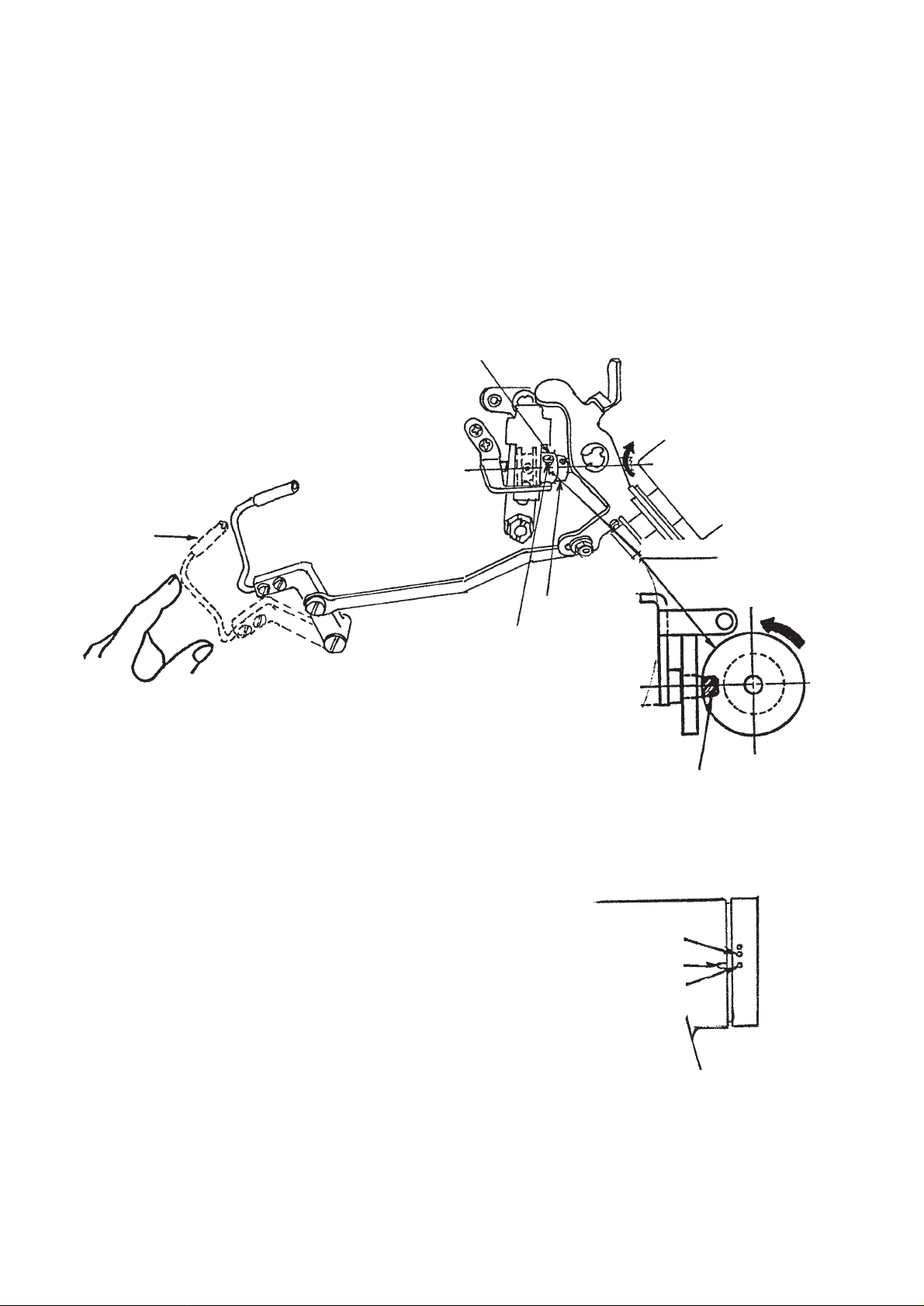
3-2 Adjusting the wiper (WB type)
1. Adjusting the wiper position
Adjust the wiper position in accordance with the thickness
of fabric to be sewn.
Normally, adjust it as follows :
1) Turn the handwheel in the normal direction to align white
marker dot (1) with marker dot (2) on the machine arm.
2) Insert wiper (3) into wiper shaft (4) so that a clearance
of 2 mm is provided between the top end of the wiper
and the top end of the needle. At this time, adjust so
that the distance from the flat section of the wiper to
the center of the needle is 1 mm. Securely fix the wiper
with wiper adjusting screw (5) as if pressing wiper (3)
with wiper collar (6) .
[Caution] Do not loosen the wiper solenoid setscrew.
When the wiper is not used, turn OFF the
wiper seesaw switch.
Wiper seesaw
switch
(4)
(3)
Fig. 6
1 mm
Fig. 7
2 mm
(2)
(1)
(6)
(5)
−9 −
Fig. 8
Page 13

3-3 Principle of thread trimming
1. Blade point of hook scoops needle thread.
Fig. 9
3. Moving knife catches needle and bobbin threads (advances).
Fig. 10
3-4 Sequence of thread trimming
Knife catches
Low speed to
high speed
Depress front part
of pedal
Depress back
part of pedal
Detection
Thread handling
Thread trimmer
solenoid is actuated.
2. Moving knife handles threads (recedes).
4. Thread trimming
thread.
End of tension release
Cam and roller are
disengaged.
Power
switch ON
Thread
trimming
Up-stop
signal
Thread trimmer solenoid OFF
Sewing machine stops
with needle up.
Needle goes up.
Reverse feed stitching at
sewing start
Pedal neutral
position
Needle down
stop
Sewing machine rotates from
needle down to needle up.
Cam engagement
Tension release
Reverse feed stitching
at sewing end
[Caution] This sequence shows the state that the automatic reverse feed stitching switch is turned ON at
the start of sewing and at the end of sewing.
−10 −
Page 14

(Reference) 1. M arke r dot on th e handwheel shows the standard value of cam timing. The timing can be more advanced
by 2˚ or more delayed by 5˚ than that in case of cotton thread or synthetic thread. At this time, however,
confirm that moving knife securely separates two pieces of needle thread at the bottom face of throat
plate. If the cam timing is excessively advanced or delayed, the needle thread remaining at the top of
needle will be shorter and may slip from the needle immediately after thread trimming. In addition,
roller may not enter the groove of thread trimmer cam. So, be careful.
2. Basically, the thread trimmer cam timing is common to cotton thread and synthetic thread. For the thin
synthetic thread, however, if the following troubles occur :
① One or several stitches skip at the start of sewing.
② Thread slips from needle at the start of sewing.
Perform the following adjustments for synthetic thread (special) (In case of thin threads)
③ Align marker dot on the machine arm (Fig 13 (3)) with green marker dot on the handwheel (Fig.
13 (1)) and adjust thread tension No. 1 to lengthen the thread remaining on the needle after
thread trimming within the range that nothing interferes with the finish of sewing.
④ Make one stitch of soft start at the start of sewing.
[Caution] Adjustment ① is not applied to thick threads.
When thread trimmer cam timing is delayed (in the direction of green), phenomena such as
dispersion of adjustment, non-trimming of thread without completing thread trimming depending
on the kinds of threads may occur.
In this case, slightly delay the needle upper stop position.
−11 −
Page 15
3-5 Observing and adjusting the thread trimmer cam timing
1) Proper observing of the thread trimmer cam timing
Thread trimmer cam timing for both cotton and synthetic threads can be easily adjusted by aligning marker dot
on the machine arm with that on the handwheel.
Tilt the machine head, turn the handwheel by hand until the thread take-up lever goes up slightly near the
upper dead point, press thread take-up picker (Fig. 12 (1)) to the right with fingers, and roller enters the cam
groove of thread trimmer cam to engage with each other. At the same state, turn the handwheel in the reverse
direction as against the normal operation of the sewing machine, and there is a position where the sewing
machine does not rotate. At this time, adjust the cam timing so that marker dot (Fig. 13 (1)) of the machine arm
shown in Fig. 13 is aligned with marker dot (Fig. 13 (1)) on the handwheel. This is the cam timing for cotton
thread and synthetic thread.
Thread trimmer cam
(1)
2) Adjusting the thread trimmer cam timing
First, loosen two setscrews (Fig. 12) in the thread
trimmer cam in the order of No. 1 and No. 2, and align
marker dot on the hand wheel with marker dot on the
machine arm. (Fig. 13 (1) and red (2) or green (3) )
Next, pressing thread take-up picker (Fig. 12 (1) ) to
the right, engsage cam and roller, turn cam only with
finger top in the reverse direction as against the rotating
direction of hook driving shaft without turning the hook
driving shaft (arrow mark in Fig. 12). Press the cam to
roller (Fig. 12) at the position where the cam does not
rotate, and tighten setscrews in the cam in the order of
No. 2 and No. 1.
When the cam collar has not been moved, press the
thread trimmer cam to the cam collar and tighten the
setscrews in the order of No. 2 and No. 1.
Setscrew No. 2
Fig. 12
Cam collar
Thread trimmer cam
Turn cam by hand in
this direction.
Roller
(3)
Green
(1)
(2)
Red
Fig. 13
−12 −
Page 16

3-6 Adjusting the position of moving knife movement
1) Proper movement of the moving knife
The position of moving knife when it moves until it will go no further is the position where the front top end of
moving knife is receded 2.5 to 3 mm from the center of the needle. When the amount of recession is excessively
small, the moving knife cannot scoop needle thread or bobbin thread when trimming thread, and if the amount
is excessively large, feed dog may come in contact with moving knife. Therefore, properly adjust the moving
knife position.
Reference for positioning the moving knife at the predetermined position is the position where the V groove
indicated on the knife installing base is aligned with the periphery of moving knife.
Moving knife
V groove for positioning
moving knife
2.5 to 3 mm
0.5 mm
(0.2 to 0.7)
Center of needle
When moving knife recedes most.
Fig. 14
Predetermined position
2) Adjusting the moving knife position
Adjustment is performed by changing the right and left positions of moving knife link pin (Fig. 15 (1)) when the
sewing machine stops.
① Loosen the lock nut of moving knife link pin (Fig. 15 (1)).
② Following the predetermined position in Fig. 14, move the moving knife link pin to the left and right so that
V groove (Fig. 14) for positioning moving knife on the knife installing base is aligned with the periphery of
moving knife.
③ Tighten the lock nut of moving knife link pin at the proper position.
Set the position of moving knife pin to the right to increase the amount of recession, and to the left to
decrease the amount.
3) When adjustment cannot be performed by moving knife link pin only
① Loosen the lock nut of moving knife link pin (Fig. 15 (1)).
−13 −
Page 17

② Adjust so that the center of moving knife link pin
is aligned with V groove (Fig. 15 (2)) of the center
of slot in knife driving arm (Fig. 15 (3)), and tighten
the lock nut to fix the pin.
③ Loosen two setscrews (Fig. 15 (4)) in driving arm
stopper (Fig. 15 (5)).
④ Move knife driving arm (Fig. 15 (2)) so that V
groove (Fig. 14) on the knife installing base is
aligned with the periphery of moving knife, press
it to driving arm stopper (Fig. 15 (4)) at that
position, and tighten setscrews (Fig. 15 (5)).
(4)
(5)
(2)
(7)
(6)
(3)
(1)
Fig. 15
⑤ Loosen the respective two setscrews in thread trimmer cam (Fig. 15 (7)) and cam collar (Fig. 15 (6)).
⑥ Align marker dot (red : Fig. 13 (2) or green (3)) on the handwheel with marker dot (Fig. 13 (1)) on the
machine arm.
⑦ Turn with finger top setscrew No. 2 (Fig. 15 (7)) in the thread trimmer cam so that it comes to this side, and
press the thread take-up picker to the right when the setscrew comes to this side.
⑧ Move the cam to the right and left to engage the cam with the roller.
⑨ In this state, lightly pulling the cam to the right, move it in the direction of arrow (this side) until it will rotate
no further.
⑩ Temporarily tighten setscrew No. 2 (Fig. 15 (7))
in the cam.
⑪At this time, check the following matters :
a) Marker dot on the handwheel is aligned with
that on the machine arm.
b) Roller smoothly enters the groove in the cam.
c) Amount of recession of knife is 2.5 to 3 mm
(SH : 3 to 3.5 mm).
⑫ Securely tighten two setscrews in the cam.
⑬ Press cam collar to the cam, and tighten one
setscrew.
Fig. 16
[Caution] ○ Amount of recession of knife is largely affected even when adjustment of left and right
positions of moving knife link pin is finely performed.
○ Check whether moving knife handles thread as shown in Fig. 16.
−14 −
Page 18

3-7 Properly installing the counter knife
The dimension of proper installation of the counter knife is as shown in Fig. 17. The standard distance from thread
guide for knife attached so that needle enters the center of window to the top end of counter knife blade is 0.5
mm.
At this time, a clearance of approximate
4 mm is provided between the center of
needle and the top end of counter knife
blade.
The top end of counter knife blade is 0.6
mm above the installing face. (Fig. 18)
Sharpness will change when installing
angle of the top end of counter knife blade
Moving knife
Thread guide
for knife
Center of needle
Approx.
4 mm
is changed. Sharpness is shown only
when cutting blade sections of counter
0.5 mm
knife and moving knife are closely
engaged with each other.
When adjusting or replacing the counter
knife, be sure to check the sharpness and
(3)
(2)
Shorter Longer
Length of thread after trimming
adjust the installing angle of counter knife.
Counter knife can be installed by moving
Fig. 17
to the right from the standard installing
position.
At this time, the feeding length of needle
thread and bobbin thread is lengthened
more not only as much as the moving
Counter knife
distance of knife than the standard time,
but also thread trimming timing is delayed.
As a result, the length of needle thread
0.6 mm
Fig. 18
remaining at the top end of needle is extra
lengthened. (Fig. 20)
For the synthetic thread, move counter knife to the right to delay thread trimming timing.
To completely adjust, however, it is also necessary to adjust thread trimmer cam timing.
Bottom section of throat
plate (Machine bed)
Counter knife
(1)
Moving knife
To be center
Counter knife
Fig. 19
−15 −
Hook
When counter knife is
moved to the right
Standard
Moving knife
Thread take-up picker
Fig. 20
Page 19

Properly installing the thread guide for knife
Install the thread guide for knife so that the needle enters just in the center of the window (hole).
3-8 Rising amount of the thread tension disk No. 2
1) Observing the rising amount of the thread tension disk No. 2
Lift the presser foot at the position where the thread take-up lever comes slightly to this side of its upper dead
point. Then, check that the rising amount of the thread tension disk No. 2 is 0.5 to 1mm when thread take-up
picker (Fig. 12 (1)) is pressed to the right.
2) Adjusting the rising amount of the thread tension
disk No. 2
① To increase the rising amount, loosen screw
(Fig. 21 (1)) and move thread release wire (2)
to the right.
② To decrease the rising amount, loosen screw
(1) and move thread release wire (2) to the
left. After performing adjustment, securely
tighten screw (1).
Fig. 21
(2)
(1)
3-9 Sharpening the knife blade
The shape of blade top of the counter knife affects most the sharpness of the knife.
In many cases, the sharpness is improved by sharpening the blade of the counter knife only.
It is important that the blade face of the counter knife comes in contact with the blade section of the moving knife.
○ The sharpness is improved by sharpening face A in Fig. 22 only. (Pay attention to the angle shown in Fig. 22.)
Moving knife
Take corner and polish well.
Sharpen this face. (Face A)
Blade top (Face B)
X
Fig. 22
Counter knife
C and D sections of moving knife should
simultaneously come in contact with counter knife.
D
Fig. 23
○ The sharpness is deteriorated when the top end of face B has been worn out and got round. Carefully sharpen
the blade without changing the angle.
Counter knife
C
−16 −
Page 20

○ When the sharpness is insufficient although the blade
face is enough sharpened, it is because the left and
right blade faces of moving knife and counter knife
do not simulataneously come in contact with each
other. At this time, adjust the inclination of the counter
knife.
(Reference) To improve the contact of the blades
of moving knife and counter knife, it is
effective to change the angle of the
arrow mark shown in Fig. 24.
When the side of D in Fig. 23 is hard to
cut, decrease this angle, and when the
side of C is hard to cut, increase the
angle.
3-10 Replacing the moving knife
When replacing the moving knife, replace it in the
following procedure.
1) Remove moving knife hinge screw (Fig. 26 (1)).
2) Slide moving knife link (Fig. 26 (2)) to this side, and
draw moving knife link (2) from knife forked pin (Fig.
26 (3)).
3) Loosen and take out moving knife hinge screw (Fig.
25 (3)) using 3 mm hexagonal wrenck key (Fig. 25
(4)).
4) Loosen and remove knife forked base hinge screw
(Fig. 25 (1)). Lift up knife forked base (Fig. 25 (2))
and remove the pin of moving knife from the forked
groove in the knife forked base.
5) Remover the pin of moving knife, slide the moving
knife to the left and take it out from the bottom face
of knife forked base.
Counter knife
Fig. 24
(1)
(2)
(3)
(4)
Fig. 25
Perform installation in the reverse order of the
aforementioned procedure.
When tightening the moving knife hinge screw, move
the moving knife by hand and check that it smoothly
moves without play.
Next, securely insert the forked groove in the knife forked
base into the moving knife pin, and tighten the knife
forked base hinge screw.
Insert the moving knife link into knife forked pin (Fig. 26
(3)), and attch moving knife link hinge screw
(Fig. 26
(1)
Finally, move the moving knife link to the left and right,
and check that the moving knife moves.
−17 −
(1)
).
(2)
(3)
Fig. 26
Page 21

3-11 Replacing the thread guide for knife
When replacing the thread guide for knife, loosen screws (2) and (3) shown in Fig. 17, and replace it with screw
(1) tightened.
If the installing angle of counter knife is moved, perform re-adjustment referring to the item of 3-7 “Properly
installing the counter knife”.
3-12 Adjusting the thread take-up picker
If thread take-up picker (Fig. 27 (3)) excessively enters in the direction of bobbin case when trimming thread,
bobbin does not rotate and bobbin thread is trimmed shorter than the standard. As a result, slip-off of thread
occurs at the start of sewing.
On the contrary, if it insufficiently enters, needle thread slips from the top end of thread take-up picker when
trimming thread. As a result, needle thread remaining at the needle top after thread trimming is shorter resulting
in slip-off of thread.
Marker line
(3)
(4)
Fig. 27
1) Proper position of the thread take-up picker
Adjust the thread take-up picker so that bobbin thread is
lightly pulled out in the state that clutch plate (Fig. 27 (1))
is pressed in the direction of the arrow mark (right side).
At this time, as shown in Fig. 28, adjust so that a clearance
of 1.0 to 1.5 mm is provided between the top end of thread
take-up picker (bobbin presser) and the notch in the upper
section of bobbin. In addtion, after the clutch plate has
been pressed to the right, lightly press thread take-up
picker (3) and adjust so that the rear end of bobbin presser
is aligned with the marker line on the thread take-up picker
in the state that the play is removed.
(2)
(1)
1.0 to 1.5 mm
Fig. 28
2) Adjusting the thread take-up picker
Loosen screws (Fig. 27 (4)) and adjust so that the top end (bobbin presser) of thread take-up picker is located
as shown in Fig. 28.
To adjust the depth of thread take-up picker, move the position of picker link pin (Fig. 27 (2)).
After performing adjustment, tighten the lock nut of picker lik pin.
−18 −
Page 22

3-13 Adjusting the clutch plate and the thread trimmer solenoid
The stroke of thread trimmer solenoid is 6 mm.
Installing positions of the clutch plate and the solenoid are the positions where the clearance of section A is 0.1 to
0.5 mm when the thread trimmer solenoid is drawn (Fig. 30).
In this state, tighten solenoid setscrew (Fig. 30 (10)).
(3)
Solenoid stroke 6 mm
(4)
3-14 Driving arm stopper
Driving arm
stopper
Section A
Fig. 30
Driving arm
(10)
(1)
(2)
Stopper section
stopper
A
Roller arm
Fig. 31
−19 −
Page 23

Needle
Moving knife
Needle entry position
Fig. 32
1) Press the roller arm in the direction of the arrow mark to press it to the stopper section of the thread trimmer
control plate.
2) At this time, adjust with screws (1) and (2) so that the stopper section works at the position where the moving
knife does not reach the needle entry position.
3-15 Installing/removing the knife installing base
1) Remove the hook and the bobbin case holder.
2) Lift up moving knife link (Fig. 33 (1)) to this side and remove it from knife forkd pin (Fig. 33 (2)) after removing
moving knife link hinge screw (Fig. 33 (3)).
3) Remove knife installing base setscrew (Fig. 33 (5)), and remove knife installing base (Fig. 25 (4)).
Perform the installation in the reverse order of the aforementioned procedure.
(5)
(2)
(3)
(4)
(5)
Fig. 33
(1)
−20 −
Page 24

3-16 Adjusting the position of the touch-back switch
The height of the touch-back switch can be changed by turning push button (1). When you desire to further
change the position, loosen setscrew (2) to slide it up or down, or loosen setscrew (3) to move it up or down
together with switch base (4).
In addition, tightening torque of setscrew (2) should be moderate since the screw is tightened in the plastic base.
And, securely and strongly tighten setscrew (3).
(3)
(2)
(4)
(1)
3-17 Adjusting the position of the handwheel
When removing the handwheel, be sure to check the following matters for adjustment.
1) Provide a clearance of 1 mm between handwheel
(1) and the pulley cover. If the clearance is too narrow,
the position detector solenoid comes in contact with
the synchronizer. If it is too wide, defective detection
may occur.
2) Be sure to adjust screw No. 1 in the handwheel to
the flat section of the motor shaft, and tighten the
screws in the order of No. 1 and No. 2.
1 mm
3-18 Adjusting the automatic presser lifter (AK118)
1) Remove the side plate of the sewing machine head
and remove hinge screw (2) of knee lifter side rod (1).
(2)
(1)
−21 −
Page 25

2) Remove hinge screw (4) in knee lifter link (3),
replace the link with knee lifter link (5) to which
spring (6) supplied with the machine is set, and
install it with hinge screw (7).
At this time, tilt the machine head and check that
knee lifter connecting rod (8) enters in the hole of
connecting rod guide (9).
3) Tighten knee lifter side rod pin (10) with knee lifter
link (5) which has been replaced using screw.
Then, install knee lifter side rod with pin (1).
(3)
(4)
(Caution) 1. Knee lifter side rod is easily
loosened. Securely tighten it.
2. Apply grease to the respective
hinge screw sections.
4) Install knee lifter link spring retainer (14) on wire
presser base (15) so that tension release wire (12)
and oil pipe (13) are pressed with the hook. At
this time, pay attention to the routing of oil pipe
(13) and wire (12).
5) Hook knee lifter link spring (6) to the notch of knee
lifter link spring retainer (14).
6) Install the AK device (asm.) (16) on the machine
arm.
At this time, install it so that the slot of solenoid
link (17) is set to knee lifter side rod pin (10).
(Caution) Apply grease to the slot of solenoid link
(17).
(8)
(5)
(7)
(6)
(10)
(1)
(11)
(9)
(8)
(16)
Slot
Apply grease.
(10)
−22 −
(6)
(10)
(14)
(12)
(13)
(15)
Notch
(14)
Page 26

7) Pass cord (16) of AK device (asm.) through the
hole of the table and insert 2P connector (18) into
2P connector (19) (2P white CN9) located on the
control circuit board.
Arrange the cord with other cords using cord
clamp (20) and cable band (21) so that they do
not hang loose.
8) Bundle the cord with other cords using the cord
band supplied with the machine.
(18)
(20)
(21)
9) Remove the face plate of the machine head, and
lower the presser foot to make a state that lifting
plate (22)is pressed down. Turn solenoid shaft
(23) to the left with screwdriver (A) and tighten
screw (24) using hexagonal wrench key (B). At
this time, set the solenoid in the state that it is
pressed in the direction of the arrow mark.
(Caution) Check that there is a clearance
between the bottom face of presser bar
guide bracket (25) and the top end of
lifting plate (22) in the state that the
presser foot comes in close contact
with the throat plate.
10) When using the AK device, use it after removing
the head support rod on the table.
(22)
(A)
(24)
(B)
(23)
Clearance
−23 −
(25)
Page 27
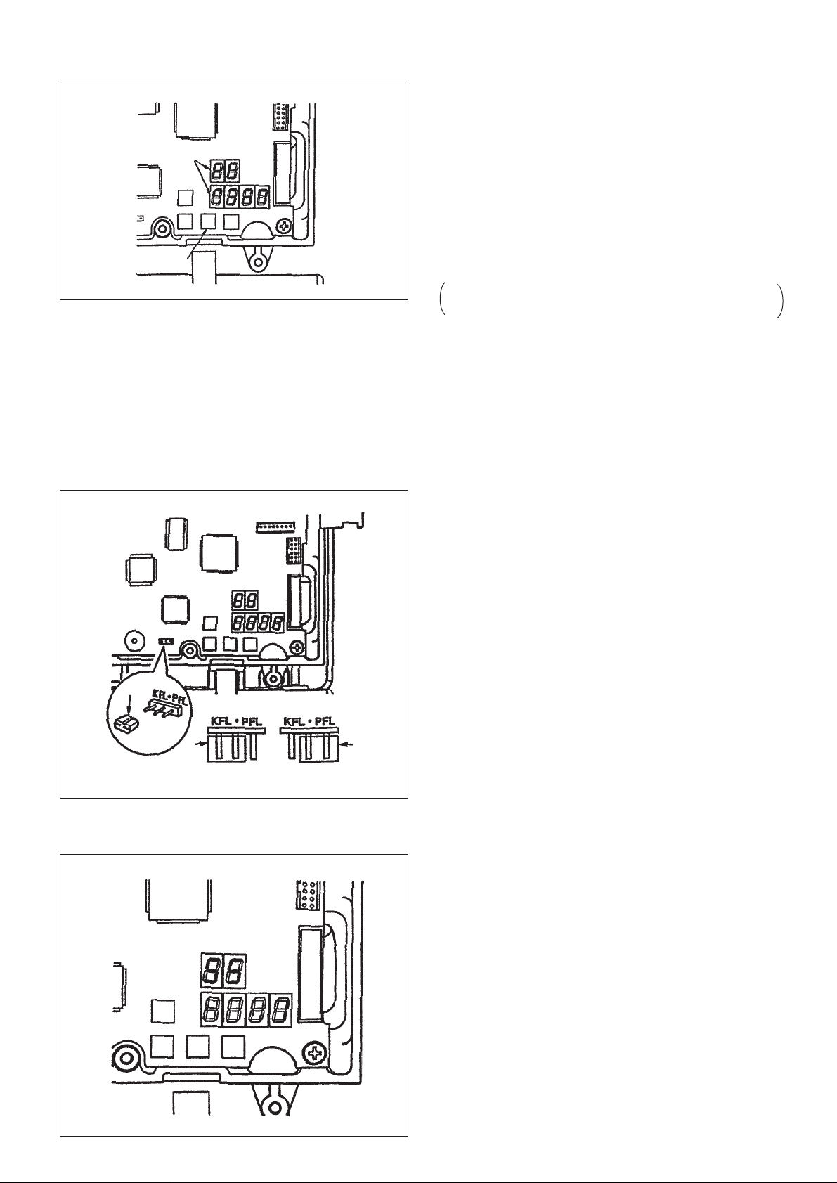
Selecting the automatic presser lifting function
1) Pressing switch (1) in the control box, turn ON the
power switch.
2) LED will be displayed (2) (FL ON) with “beep”, and
the automatic presser lifting function becomes
(2)
effective.
3) Turn OFF the switch once and again turn it ON.
4) Repeat operations 1) through 3), and LED display will
be “FL ON. The automatic presser lifting function does
not work.
FL ON : Automatic presser lifting function is effective.
(1)
FL OFF : Automatic presser lifting function does not work.
Similarly, the presser foot does not automatically go
up when programmed stitching is completed.
(Caution) 1. Turn ON the power again after one second or more has passed without fail.
(If the action of ON/OFF of the power is quick, setting may not be well changed over.)
2. If this function is not properly selected, the automatic presser lifter does not work.
3. If “FL ON” is selected without installing the automatic presser lifter, the starting at the start
of sewing is momentarily delayed. In addition, the touch-back switch may not work. Be sure
to select “FL OFF” when the automatic presser lifter is not installed.
Selecting the presser foot lifting by pedal
The presser foot can be lifted with the operation of
depressing the back part of the pedal by changing jumper
(1) located on the control circuit board.
Follow the silk screen indication located on the upper side
of the jumper to change.
PFL : Presser foot can be lifted by depressing the back
part of the pedal.
KFL : Presser lifting operation by pedal is not performed.
(Caution) 1. When changing the jumper, be sure to
do the work after turning OFF the power.
(1)
If the jumper is changed while the power
is ON, the setting does not change. The
main unit may be broken.
2. When PFL is selected, the thread
(1)
KFL setting PFL setting
(1)
trimming point will automatically
descends.
Selecting the automatic presser foot lifting after thread trimming
1) This function can be selected by function setting No.
55 of the SC-900.
1 : Presser foot automatically goes up after thread
trimming.
(Standard setting at the time of delivery)
(When the programmed stitcing is selected with CP-
360 panel, it works according to the setting of the
operation panel.)
0 : Automatic presser foot lifting after thread trimming
is not performed.
(Similarly, the presser foot does not automatically
go up when the programmed stitching is
completed.)
(Caution) For the details of the function setting, refer
−24 −
to the Instruction Manual for the SC-900.
Page 28

3-19 Optionals (Presser foot micro-lifter)
When straight stitching is not performed since slip-off of fabrics occurs dut to the pressure of presser foot in case
of fluffy masterials such as velevet or the like, or hard-to-sew materials, if presser foot micro-lifter (2311056) is
used, the presser foot can be minutely lifted at the face plate section with ease, and sewing can be performed. As
a result, handling and finish of fabrics are improved.
(Assembling the presser foot micro-lifter)
1) Remove the setscrew in the hand lifter, and remove the plastic
hand lifter.
2) Remove the face plate, insert micro-lifter hand lifter (1) into hand
lifter cam shaft (2) while pressing hand lifter cam shaft (2) with
fingers so that it does not move in the direction of inside of the
machine arm, and securely tighten it with setscrew (3).
3) Temporarily tighten two setscrews under the face plate, insert
collar (4) supplied with the machine into the upper setscrew
section, insert guide hole A of installing base (5) into the top
end of hand lifter cam shaft, and securely tighten the micro-lifter
with setscrew (6) through washer (7) while checking that microlifter hand lifter (1) lightly moves.
(Adjustment)
1) Loosen micro-lifter nut (8), turn micro-lifter hand lifter knob (9) to
this side, and the presser foot gradually goes up.
2) Tighten nut (8) to fix the micro-lifter at the position where the
optimum condition of the sewing materials is obtained after trial
sewing.
A
(A)
(3)
(1)
(7)
(6)
(8)
(5)
(9)
(2)
3-20 AE-8 (Bobbin thread remaining amount detector)
When the amount of remaining bobbin thread reaches the set value, buzzer will sound to warn the operator not to
perform the next operation of depressing the front part of the pedal.
It is especially effective for the splicing and the process where resewing is not possible.
For installation, optional printed circuit board A (M97014610A0) which is separately available is required.
For the details, refer to the Instruction Manual attached at the time of purcahse of the device.
(Caution) This device cannot be used with DS and DF types. When it is compelled, use this device with
existing RP hook 11079456 and at sewing speed of 3,000 rpm or less.
3-21 ED-4 (Compact material end sensor)
When the sensor detects a material end, the sewing machine automatically stops and thread trimming is
performed.This enhances productivity by allowing the operator to conduct sewing work without running to look
out for missing stitches.
For installation, optional printed circuit board A (M9701460A0) which is separately available is required.
Refer to the Instruction Manual attached at the time of purchase of the device.
3-22 PK-70 and -71 (3-step pedal)
Refer to the Instruction Manual attached at the time of purchase of the device.
−25 −
Page 29

3-23 Adjusting the tension release change-over
When the sole of the presser foot is lifted 3.5 mm or more with the knee pad or AK device, the tension release
works and the thread tension disk rises. As a result, tension is not applied to the needle thread.
When the presser foot is lifted by the thickness of the overlapped section of the fabric instead of the knee lifter, the
tension release does not work.
Especially when the knee lifter is used at the thick section to handle the material during sewing, thread tension
may become deffective.
In this case, the tension release can be released by performing the following adjustments.
(Thread trimming function is not affected since the tension release works when thread trimming.)
1) Remove rubber cap (1) located on the rear face of face plate of
the machine head.
When the machine is provided with the wiper, perform the work
after removing the wiper base.
2) Loosen change-over screw (2) with 3 mm hexagonal wrenck
key. Turn it downward until it will go no further, and tighten it
again. Tension release is possible with the knee lifter. Turn it
upward until it will go no further, and tighten it again. Tension
release is not possible with the knee lifter.
(1)
(2)
3-24 Adjusting the presser foot micro-lifter
The presser foot can be minutely lifted with ease using the microlifter screw installed on the machine head to perform the sewing.
1) Loosen micro-lifter nut (1), and turn micro-lifter screw (2) to the
right to gradually lift the presser foot.
2) Tightn and fix nut (1) at the position where the optimum condition
of the sewing material is obtained through trial sewing.
(Caution) When the micro-lifter is not used, make the height of
micro-lifter screw (2) from its installing face on the
machine arm 11 mm or more.
when the micro-lifter is working, the presser foot is
in the state that it is rising under the standard sewing
condition. As a result, feed force is excessively
deteriorated.
3-25 Installing the operation panel
If the installation of the operation panel is improper, noise of snarl
may occur when the machine runs at high speed.
When installing the panel, remove two setscrews (2) in the side
plate and install it with the screws supplied with the panel in the
state that rubber (1) of the panel installing plate is securely pressed
to the upper face of the machine arm.
(1)
(2)
(1)
11mm or more
(1)
−26 −
(2)
Page 30

3-26 Dimensions of table
The bed size of this machine is the same as that of JUKI LH model. This machine cannot be set to the table for the
exising lockstitch sewing machines.
Refer to the following dimensions only when JUKI exclusive table is not used since the main dimensions of the
table are described below.
[Reference dimensions of table]
C
Section C
Rubber cushion installing
drawing for reference
C1 chamfer
E
Section E
1
ø26
± 0.5
8
19.5
Section A (3 places)
Section D (2 places)
23.5 ± 0.5
Section E (2 places)
ø8.5
B
A
C
C1 chamfer
JUKI stand installing position
D
F (reverse side)
17.5 ±0.5
Section C (2 places)
E
ø16
ø26
9.5 ± 1
Section B (1 place)
32 ± 1
R2
25
R30
Section F
R2
C1.5 to 2.5 chamfer
(To prevent machine from
being caught when tilting
it)
(40)
−27 −
Page 31

3-27 Points of adjustment and assembly of the feed mechanism
(Adjusting the feed driving components)
* To obtain the movement in the direction of the horizontal feed, feed rocker shaft (1) is rocked by means of feed
rocker cam attached to feed driving shaft (2), connecting links A (4) and B (3) of feed rocker rod (19), feed
adjusting link (5), and feed rocker arm (6).
* Seizure, abnormal exothermic, pitch error, lever snarl, or defective return of lever will result due to the torque
of the sewing machine unless centering and play adjustment of the aforementiond parts are securly performed.
Perform readjustment in the following procedure when these phenomena are likely to occur.
1) Remove the lid of the gear box.
Refer to the item 3-34 for removing and attaching it.
2) Remove rubber cap (7) located on the side face of
the machine bed and loosen setscrew (8) in the feed
rocker arm.
* Apply sealant to the rubber cap to prevent it from oil
blurredness when attaching it again.
3) Loosen two setscrews (13) in the feed rocker cam.
When attaching the setscrew No. 1 again, check that
it is set on the flat section.
When loosening amount of the setscrew No. 1 is
small, it can be saved for the setscrew to be slipped
from the flat section.
4) When there is no trouble with feed adjusting link (5),
the strain can be removed by adjusting the lateral
position of the feed rocker cam or the feed rocker
arm. Turn the handwheel several times and the feed
rocker cam moves to the position where there is no
strain. In this state, quietly tighten setscrew No. 1.
Further, tighten setscrew No. 2.
5) Then, similarly, turning the handwheel by hand, adjust
feed rocker arm (6) to the position where there is no
strain, and tighten the setscrew.
6) If there is a play when pressing feed adjusting link
(5) to the right and left, perform the following
adjustments before adjustments 4) and 5).
7) Remove rubber cap (9) in the adjusting link fulcrum
shaft and loosen setscrew (10) in the fulcrum shaft,
insert a screwdriver from the hole from which the
rubber cap is removed to lightly press the fulcrum
shaft, then securely tighten setscrew (10) in the
fulcrum shaft.
The play in this section will affect largely the lever
snarl. It is the point to assemble it while lightly pressing
the fulcrum shaft.
* When the adjusting link does not smoothly move
although there is no lateral play in adjusting link
connecting link (14), remove rubber cap (11) in the
adjusting link fulcrum shaft, loosen setscrew (12) in
the fulcrum shaft on this side, move the feed lever up
and down to fit adjusting link (5), and adjust fulcrum
shaft (15) to the position where the strain does not
occur.
(1)
(11)
(19)
(15)
(12)
(8)
(4)
(3)
(7)
(6)
(5)
(14)
(13)
(10)
(9)
(16)
(2)
(17)
(18)
−28 −
Page 32

(Adjusting the feed adjustment components)
* When there is a lateral play in feed changing shaft (16),
lever snarl, or longitudinal play of the feed dog will be
large. Securely tighten setscrew (17) in the feed changing
shaft arm A with a rather large-sized screwdriver, and
assemble the shaft with thrust collar (18) so that it smoothly
turns without play. (Refer to the illustraion on the previous
page.)
[Adjusting the feed “0” point]
Adjust the initial position from the adjusting link to the feed
adjusting base in the following procedure.
1) Remove the side plate, loosen two setscrews (4) in the
feed adjusting base, turn feed adjusting pin (5) with
wrench, and temporarily tighten two setscrews (4) of the
feed adjusting pin in the state that notch A of the pin comes
to the side plate side.
2) Remove the reverse feed solenoid, and set the feed dial
to “0”.
3) Loosen setscrew (7) in feed changing shaft arm B (6),
move adjusting link (5) (illustration on the previous page)
with fingers, and securely tighten setscrew (7) in feed
changing shaft arm B (6) at the position where connecting
link A (8) is aligned with connecting link B (9).
* Set the lateral position of feed changing shaft arm B to
the position where a clearance of 1 mm is provided
between the arm and the metal, and check that strain does
not occur in adjusting rod (11).
(5)
A
(4)
(11)
(10)
(18)
Clearance
[Adjusting the ratio of normal to reverse feed]
1) After adjusting feed “0” point, and actually place a piece
of paper under the presser foot. Then, make normal feed
of 10 stitches and reverse feed of 10 stitches by operation
of the feed lever to check that proper ratio of normal to
reverse feed is obtained. Adjust the feed dial with three
graduations. If the ratio of normal to reverse feed is not
proper, gradually turn the feed adjusting base pin with
wrench and securely tighten two setscrews (4) of the pin
at the position where the ratio of normal to reverse feed is
proper since feed adjusting base pin (5) is eccentric.
* Turning clockwise feed adjusting base pin (5) increases
normal feed, and counterclockwise increases reverse feed.
[Adjusting the position of the feed lever]
1) Adjust the tightening position of feed lever arm (10), when
the feed dial is set to graduation “5”, so that a clearance is
provided between the arm and the claw section of feed
adjusting rod (11).
After the adjustment, make a slight play when the
graduation of the feed dial is “5” and the feed lever is lightly
pressed. If the play is excessive, operability is deteriorated,
and if it is excessively small, the feed lever may move by
the shock at the time of automatic reverse feed.
[Automatic back solenoid]
1) Loosen setscrew (1) and move the solenoid up or down
to adjust the position of the automatic back solenoid.
Setting the graduation of the feed dial at “5”, press the
feed lever until it will go no further. At this time, make a
state that plunger rubber (2) in the solenoid exactly moves,
and securely tighten setscrew (1) in the solenoid installing
base with a rather large-sized screwdriver.
(6)
(7)
(8)
(8)
To be aligned.
(9)
(9)
(1)
(1)
(2)
−29 −
Page 33

(Adjusting the feed mechanism of feed base components)
[Adjusting the longitudinal position of the feed dog]
1) Adjust the marker dot of feed driving base pin (1) to
the right and feed rocker base pin (2) to the upper
right at approximately 45˚.
(Adjust in the state when adjustment of the feed base
pin has been completed.)
2) Set the feed dial at “5”.
3) Temporarily tighten the setscrew in feed rocker base
arm (3), turn the handwheel to observe the symmetry
of the feed dog in terms of the groove of the throat
plate. Tighten the setscrew in feed rocker base arm
(3) at the position where the central symmetry is
obtained.
[Adjusting the lateral position of the feed dog]
1) After adjusting the longitudinal position of the feed
dog, in the state that the feed dog is fixed in the almost
center of the setscrew in the feed base, check the
clearance in the lateral direction of the throat plate.
If the slippage is small, it can be adjusted with the
play in the installing hole of the feed dog. If it is large,
however, readjust the lateral position of feed driving
base arm (4) and feed rocker base arm (3).
* Loosen setscrew (4) in the feed driving cam, loosen
the swetscrew in the feed rocker base arm (3), and
adjust the lateral position of the feed dog.
Determine the longitudinal position of feed rocker arm
(3) referring to the points of adjusting the longitudinal
position of the feed dog.
* Tighten setscrew (4) in the feed driving cam in the
state that the central marker line on feed driving cam
plate (5) is aligned with marker line (6) in the feed
driving shaft.
Turn the handwheel several times to and fro by hand
before tightening to prevent the adjustment from the
state that the feed driving base arm in terms of the
feed rocker base arm is improperly positioned.
When the feed driving cam does not lightly turn before
tightening the setscrew in the feed driving cam, there
is a defective part. So, be careful.
(1)
(5)
(6)
(4)
(2)
45˚
(3)
−30 −
Page 34

(Adjusting the feed timing and dimensions of the feed base components
[Inclination and height of the feed dog]
* Standard adjustment value of the inclination of the
feed dog : Marker dot (6) in feed rocker base pin
(3) is positioned to the upper right 45˚ and marker
(1)
(5)
(3)
(6)
dot (5) in feed driving base pin (1) is positioned to
the right for reference. At this time,the inclination
(2)
of the feed dog is slightly raised to this side when
it starts going up from the top surface of the throat
plate and coming down from it.
* Making this side of the feed dog raised, bite of the fabric is improved and material slippage is decreased.
When improving puller effect with this side of the feed dog raised or changing the inclination in accordance
with the sewing conditions, loosen screws (2) and (4), and turn feed rocker base shaft (3) and feed driving
base shaft (1) with screwdriver to adjust it.
After the adjustment, fix the feed dog with screws (5) and (6) while lightly pressing with fingers feed driving and
feed rocker base shafts (1) and (3) to the rear side.
(Caution) If there is a play in the feed base, noise or defective straight stitching will result.
Max. front up
Marker dot
45˚
(4)
Marker dot
Max. this side up
Marker dot
Marker dot
Fig. 1
Fig. 2
Turn the marker dot in feed driving shaft base (1) in the upper direction to tilt the feed dog with its front up. (Fig. 1)
Turn the marker dot in feed driving shaft base (1) in the lower direction to tilt the feed dog with this side up. (Fig. 2)
However, if adjusting it with feed driving shaft base (1) only, the maximum height of the feed dog is changed.
Simultaneously perform the adjustment of raising and lowering the marker dot in feed rocker base shaft (3) when
you do not desire to change the height.
* The standard height of the feed dog is 0.8 to 0.85
mm. If the height of the feed dog is raised, feed
force is improved.However, jumping of the presser
foot at high speed or defects of light-weight
0.8 to 0.85
A
materials is likely to occur.
* If the height of the feed dog is excessively raised,
return on this side (section A side) of the feed
dog occurs and feed of materials may be affected.
If it is compelled to raise the height, adjust the
inclination of the feed dog with its front up to
decrease the return.
−31 −
Page 35

[Locus and timing of the feed dog]
☆ Locus of feed and feed driving timing in terms of the
needle can be changed by loosening setscrew (10)
in feed driving cam (9).
* Standard adjustment value is the state that marker
dot (7) is aligned with marker dot (8) in the center.
(9)
(10)
★ Loosen setscrew (9) in feed driving cam (10) and turn
it to this side (direction C), and adjust the marker line
to “-” side (Fig. A). Then, feed driving timing in terms
of feed rocker is advanced. Change in the horizontal
direction at the start of feed is decreased and the
fabric is securely fed resulting in decrease of irregular
stitches.
• Feed force is slightly decreased since the feed
dog near the end of feed lowers faster.
★ Loosen setscrew (9) in feed driving cam (10) and turn
it to the front side (direction D) , and adjust the marker
line to “+” side (Fig. B). Then, feed driving timing in
terms of feed rocker is delayed. Start of feed is smooth
and light-weight materials become hard to be
damaged although bite to the fabric is slightly
deteriorated. In addition, the feed dog securely feeds
fabric at the end of feed and puckering is reduced
due to puller effect.
Standard adjustment
(7)
(8)
(7)
Fig. A
(8)
(7)
(8)
Fig. B
(Caution) Whenever the timing of feed driving cam (9) is changed, the feed timing in terms of the needle
will be changed.
When the timing of feed driving cam is excessively changed, readjust it referring to [Adjusting
the needle and feed timing].
(Reference for the position of the feed driving shaft in terms of the needle bar)
Whether the timing of the needle and the assembling position of the feed driving shaft are in the normal position
can be checked by the following manner.
◎ When “+1” to “+3” of the marker line are positioned right above in the state that the marker line at the top end of
feed driving shaft is adjusted to the “0” position of the feed driving cam plate when the needle bar is brought to
its upper dead point, the position is normal although it is slighly different by the adjustment of timing.
Right above around here
* Reference for the position of the
feed driving cam at the needle
bar upper dead point
−32 −
Page 36

[Adjusting the needle and feed timing]
When performing adjustment of feed driving cam timing, or inclination and height of the feed dog, the needle and
feed timing will change. As a result, defective sewing or needle breakage may result.
In this case, adjust the timing in the following procedure.
1) Checking the timing of lowering of the feed dog
Turn the handwheel by hand and check the top end of needle eyelet in the state that the top end of the feed
dog is aligned with the top surface of the throat plate at the end of feed.
In this state, when the top end of the needle eyelet has been already lowered from the top surface of the throat
plate, the needle pierces the material in the state that the material is being fed when sewing the thick section,
and needle breakage due to needle bend may result.
On the contrary, when the top end of the needle eyelet is excessively positioned above the top surface of the
throat plate, stitch tightness is deteriorated.
↓
Perform adjustment in the following procedure so that the feed dog is lowered at the top end of the needle
eyelet except when intentionally changing the adjustment.
2) Adjusting the timing
☆Adjusting places are three, lower sprocket, thread trimmer cam and hook.
① Tilt the machine head, and loosen two setscrews (A) in the lower sprocket.
② Fix the feed driving cam at the feed dog lowering timing (position where the top end of the feed dog is
aligned with the top surface of the throat plate), turn the handwheel gradually to the position where the top
end of the needle eyelet is aligned with the top surface of the throat plate. In this state, tighten the two
setscrews in the lower sprocket.
(Reference value for tightening torque : 4.5N•m)
③ Loosen two setscrews in the thread trimmer cam, and adjust the cam timing to the position of the red
marker dot (green marker dot when the length of remaining needle thread is short). (Refer to the item 3-5.)
④ Adjust the hook timing by aligning the marker line on the needle bar with the bottom end of needle bar lower
bushing.
* After the aforementioned adjustment is completed, operate the sewing machine and check whether noise
occurs or thread trimmer normally works.
(A)
−33 −
Page 37

3-29 Points of adjusting and assembling the thread take-up and the needle bar mechanism
[Thread take-up]
* It is not necessary to lubricate to the thread take-up since the grease-sealed ball bearing is used.
Defective position of the thread take-up crank largely affects the durability of thread take-up and noise occurrence.
Adjust the thread take-up crank shaft in the following procedure.
1) Loosen setscrew (1) in the thread take-up crank shaft.
2) Remove the thrust of thread take-up crank (3) with thread takeup crank shaft thrust collar (2).
3) Turn the handwheel two to three times by hand to fit the position
of the thread take-up crank shaft.
4) Further, move the top end of the thread take-up to the right and
left with a finger at the position near the upper dead point of the
thread take-up, and check that there is a play.
5) Turn the handwheel again by hand at the position near the center
of the play, and securely tighten setscrew (1) in the crank shaft
in this state.
[Needle bar]
* Forced lubrication and reflux function, different from the existing sewing machines, is not provided in the face
plate section.
For SS and SH types, minimized amount of oil is supplied to the needle bar with oil wick since the maximum
number of revolution is high.
Pay attention to the following matters in order to maintain the reliability of the needle bar.
(3)
(2)
(1)
(SS, SH)
1) Check that oil wick located at the top of the oil wick support
securely comes in contact with the needle bar at the position of
approximately 5 mm below the needle bar upper metal and when
it does not, adjust the position of the oil wick support.
2) When centering of needle bar upper and lower metals is not
properly performed, seizure will result.
Touch with fingers the periphery of the needle bar lower metal
when running the sewing machine continuously for approximately
30 seconds at the speed of around 4,000 rpm, and when you
feel abnormal exothermic, there is a possibility of defective
centering.
5 mm
Correct the metal or replace it with a new one.
(DS, DF)
Different from SS and SH, the machine is not provided with the function of lubrication with oil wick.
Special grease is enclosed inside of the needle bar lower metal, and maintenance is not required until the sewing
machine runs at the speed of 4,000 rpm.
When it is compelled to replace the needle bar, however, enclose the seaparately-available exclusive grease
inside of the needle bar lower metal.
Temperature will slightly rise at the beginning of enclosing grease, and return to the normal condition when
making the machine run idle for 2 to 3 minutes at the initial stage and dirty grease of initial abration is discharged.
In this case, perform break-in operation for a few minutes, and use the machine from the state that grease is not
discharged.
* For both SS and DS, apply a rather large quantity of the exclusive grease (23640204) to the groove of the
needle bar roller.
−34 −
Page 38

3-29 Replacing the motor
1) Lossen the setscrews in the handwheel in the order
of No. 2 (2) and No. 1 (1).
2) Remove four setscrews (4) in pulley cover (3) with 4
mm hexagonal wrench key.
3) Remove the pulley cover while taking care of LED
(5) of the synchronizer.
4) Remove the side plate, and loosen coupling
setscrews (8) fixed to the motor shaft in the order of
No. 2 and No. 1.
5) Remove four motor setscrews (7) with 4 mm
hexagonal wrench key.
6-1) Gently draw out the motor, loosen coupling setscrew
(6), and remove the coupling from the motor.
6-2) Insert the coupling with small hole diameter into the
new motor, adjust No. 1 of setscrews (6) to the flat
section and tighten it. At this time, set the clearlance
betweein the motor and the coupling to 0.5 mm.
6-3) Insert the motor into the machine arm, adjust No. 1
of coupling setscrews (8) to the flat section of the
main shaft, and tighten it.
7) After installing the pulley cover, tighten the setscrews
in the order of No. 1 and No. 2 at the position where
a clearance of approximately 1 mm is provided
between the handwheel and the pulley cover.
(Caution) There is the release section A in the shaft
section of encoder case B located in the
rear of the motor.
If the handwheel is held removed, dust
enters from this section and damages the
sensor section. As a result, malfunction
of the motor may result.
When replacing the motor, take care not
to allow dust to enter from the handwheel
section, and quickly install the handwheel.
When storing the motor itself for a long
period of time, install the encoder cover
(installed at the time of delivery of motor).
(1)
(2)
(5)
(3)
(7)
(4)
(6) (8)
A
B
3-30 Replacing the timing belt
* Timing belt (23607302) is not necessary to replace unless a special trouble occtrs since the best quality
product is used.
1) Perform removing/installing of the motor referring to [3-29 Replacing the motor].
When there is no trouble with the motor, however, loosen coupling setscrew (6) without loosening setscrew
(8) , and remove the motor with couping attached.
−35 −
Page 39

* When the motor is separated from the coupling, set the
clearance between the end face of motor and the end face
of coupling to 0.5 mm when assembling them again.
2) Tilt the machine head, remove the setscrew and washer
(9) located on the rear side of the machine bed, and take
out connectingrod guide (10).
3) Pressing timing belt (11) in the right direction, turn the
timing belt to this side with fingers to remove it.
4) Replace the timing belt and assemble it in the reverse
order of the aforementioned procedure.
0.5
(11)
3-31 Points of adjusting and assembling of the bobbin winder
* Refer to the Instruction Manual for adjusting bobbin thread amount or uneven winding.
Perform the following adjustment when bobbin winder shaft (6) does not rotate.
1) Remove bobbin winder (asm.), and check whether the
rubber of bobbin winder friction wheel (7) has been
excessively worn out. If it has been excessively worn out,
replace bobbin winder friction wheel (23636301).
2) If the rubber has not been worn out so much, adjust the
position of the bobbin winder driving wheel in the following
procedure.
3) Fix the position of bobbin lever (3) of the bobbin winder
with setscrew (2) so that a clearance of approximately 1
mm is provided between bobbin winder adjust plate (2)
and lever (3). Lightly press the bobbin lever in the direction
of A at the position where the bobbin lever is released,
and remove the play. Then, tighten lever setscrew (4) so
that a clearance of approximately 11.5 mm is provided
between bobbin winder shaft (6) and adjusting plate (4).
4) Install the bobbin winder onto the machine arm.
At this time, take care not to tighten the setscrew more
strongly than necessary since the bobbin fitting base is
made of plastic.
5) Open the side plate.
6) Loosen setscrew (8) in bobbin winder driving wheel (9).
7) Pressing bobbin winder driving wheel (8) to bobbin winder
friction wheel (7) in the state that bobbin lever (3) is pressed
to bobbin winder shaft (6), fix it with setscrew (9).
8) Make bobbin lever (3) in the released state, and check
that bobbin winder shaft (6) does not rotate when turning
the handwheel. If it rotates, adjust again the pressing
pressure of bobbin winder driving wheel (8), and fix
setscrew (9) in bobbin winder driving wheel.
* After the adjustment, actually wind bobbin thread round a
bobbin, and adjust the amount of bobbin thread with bobbin
winder adjust plate (1).
(4)
(5)
B
(9)
(8)
(9)(10)
A
11.5 mm
(6)
(2)
(3)
(1)
1 mm
(7)
−36 −
Page 40

3-32 Points of adjusting and assembling of the lubrication mechanism (SS, SH)
For the SS and SH machine heads, forced lubrication to the hook is performed by the plunger pump arranged in
the hook shaft front metal. In addition, minute-quantity oil is lubricated to the needle bar through oil wick.
☆ Fill oil tank with JUKI New Defrix Oil No. 1 from the oil hole up to the marker line of the oil tank using oiler
supplied with the machine in the state that the machine head is tilted when the top end of the gauge of oil
amount indication window comes down to the lower marker line. Even when the gauge comes down to the
lower marker line, oil still remains in the oil tank for safety. However, fill oil tank with oil as soon as possible.
☆ Approximate amount of 150 cc of oil can be filled when AK device is not provided. When the AK device is
provided, the amount of oil is slightly less since the falling angle of the machine head is small.
☆ For the H type, especially pay attention to the decrease of oil since the amount of oil in the hook is large.
☆ When using the sewing machine with the head tilted to this side, the state in the oil amount indication window
does not act as reference. So, be careful. (Fill oil periodically.)
☆ To adjust the amount of oil in the hook, run the sewing machine at least for approximately 30 seconds continuously
and check in the state that the oil amount is stabilized.
☆ If the oil amount adjustment screw is excessively loosened, the O ring is removed and oil spurts out. Do not
loosen it more than 8 turns.
☆ Do not drain oil in the oil tank even when using the RP hook at the sewing speed of 4,000 rpm or less.
Oil is not lubricated to the hook shaft front metal and the needle bar. As a result, seizure may occur.
Set oil amount to “0” with the oil amount adjustment screw when using the RP hook.
☆ When removing the machine head from the table and placing it on the stand, if the machine head is laid or laid
in the opposite side, oil leaks from air vent in the oil tank. In this case, remove drain screw in the oil tank to
drain the oil, then start the work.
In addition, when attaching the drain screw, tighten it with loose tightening torque of approximate 1N•m using
a small screwdriver.
☆ Oil pipe once removed is likely to slip out resulting in oil leakage. When the pipe is removed, be sure to replace
it with a new one.
☆ When assembling the respective pipes, take care not allow them
to come in contact with moving components.
☆ When removing the hook shaft, be sure to remove the plunger
screw (1), and draw out the plunger from the groove of the hook
shaft.
(1)
[Phenomena and corrective measures of defective lubrication]
1) Oil does not come to the oil wick of the needle bar.
Phenomenon
Oil wick of the needle bar is dried up.
Cause and corrective measure
• Check whether the routing of oil wick from the float case is broken.
• Apply oil to pump oil into the oil wick when the machine has not been
used for a long period of time.
−37 −
Page 41

2) Oil amount in the hook does not appear or is small.
Phenomenon
Plunger pump does not work.
(Oil in the pipe coming from machine bed
section does not move.)
24 mm
Needle entry
position
Oil amount is small although oil in the pipe
moves.
• Plunger is not fit in the plunger groove of the hook shaft. Remove plunger
screw, spring and plunger, and check that the plunger groove is placed in
the center of the hole of machine bed.
Longitudinal position of the hook shaft is slipped or the position of the
hook shaft front metal is slipped.
End face of the hook shaft front metal is 24 mm from the needle entry
position.
When this distance is proper, correct the position of the hook shaft.
(Adjust the plunger groove to the center of the hole of machine bed.)
(It is necessary to open the gear box and correct the positions of the
gear, hook shaft bearing support and thread trimmer cam.)
• Abration or burr at the top end of the plunger
Replace the plunger.
• Defective shape at the top end of oil amount adjustment screw →
Replace.
• Hook shaft front stopper plug felt is clogged. → Replace.
• Oil hole in the lubricating hook is clogged. → Replace.
• Re-check the adjustment of oil amount (Item 3-36)
Cause and corrective measure
↓ At the time of NG (no good)
↓ At the time of NG (no good)
3) Noise of the gear is large.
Phenomena
Oil is not contained or is short in the gear box.
(1)
• Oil inside the gear box has leaked since air vent cap was not provided at
the time of transportation.
Remove cap (1) in the front face of machine bed, insert a rather hard
string into the gear box to check that oil is enough contained inside of it.
→ when oil is short, open the gear box cover and suck out with vinyl pipe
all oil contained inside the gear box. Then, fill the gear box with JUKI
New Defrix Oil No. 2 of 140 cc.
When attaching stopper plug (1), apply sealant to it.
Cause and corrective measure
3-33 Applying the exclusive grease
* For the parts other than the lubrication components, the exclusive grease (23640204) is applied to the parts
where the lubrication is necessary. Never use other grease.
Additional grease is not necessary if the machine is normally used.
When the machine is used under the severe conditions, it is effective to fill grease periodically (once in every
one or two years).
[Notes when applying grease]
1) Needle bar metal section of DS and DF machine heads
There is a grease groove inside the needle bar lower metal. Draw out the needle bar and fill the exclusive
grease to the groove section. Apply a small quantity of grease to the lower end section of the upper metal.
When filling the grease newly, make the sewing machine run idle for every 10 seconds, discharge extra
grease that occurs at this time, and wipe it out. Perform this operation several times, and use the machine
after the grease stops coming out.
−38 −
Page 42
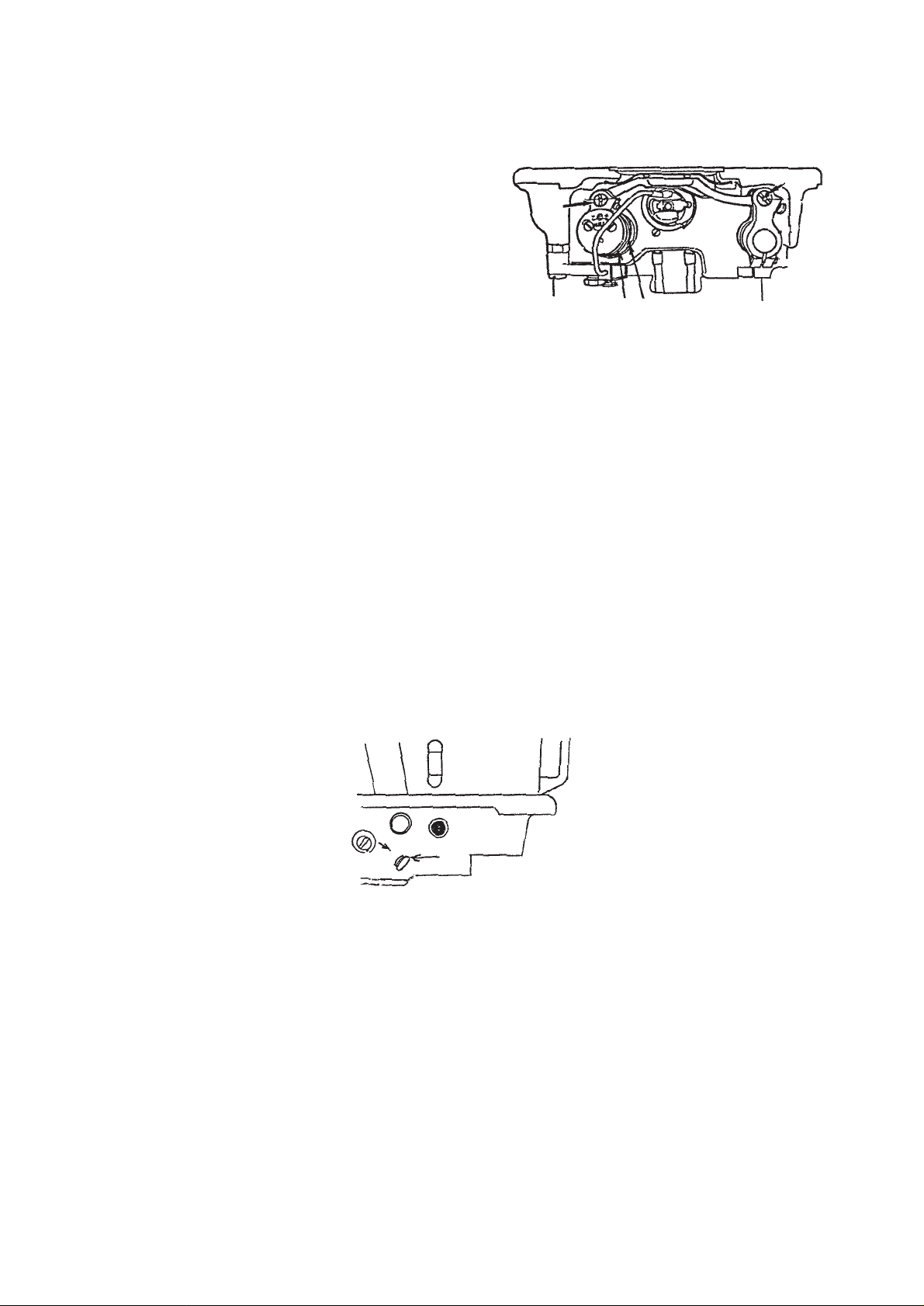
2) Feed driving base pin (2) and feed rocker base pin (3) of DS and DF machine heads
There are grease grooves in feed driving base pin (2), and feed rocker base pin (3).
When using the machine under especially severe conditions, draw out the pins, and fill periodically the exclusive
grease into the grease grooves.
3) Feed driving base arm and feed driving cam
Exclusive grease is filled to the bearing section inside
(2)
feed driving base arm (5) and feed driving cam (4).
For DS machine head, when the machine is used
under especially severe conditions, it is effective to
periodically add a few amount of grease to this
(5) (4)
section.
3-34 Removing/attaching the gear box cover
Do not open the gear box unless a trouble occurs.
When it is compelled to open it, take care of the following matters.
* Prepare a new gear box cover packing (23628100) before starting the work.
1) Tilt the machine head and prepare an oil receiver under the gear box.
2) Loosen the tension release wire presser and the pipe presser screw, and remove the wire and the pipe from
the cover.
3) Remove the gear box setscrew, and drain oil contained inside the box.
4) When the maintenance of the inside is completed, close the gear box cover.
At this time, replace the packing with a new one. In addition, wipe clean the oil on the cover and the bed
connecting plane.
Turn the setscrews one more to tighten further after tightening all setscrews to securely tighten them.
5) Remove plug (1) in the front face of machine bed, and fill JUKI Defrix Oil No. 2 of 140 cc.
When attaching plug (1) , apply sealant to it.
(3)
(1)
−39 −
Page 43

3-35 Points of adjuting the sewing
Adjusting the needle and the hook
Align hook blade point (1) with the center of needle (2) when the needle bar goes up from its lowest poisition and
the lower end of the needle bar metal is aligned with marker line B on the needle bar.
At this time, the standard clearance between the needle and the hook blade point is approximately 0.04 to 0.1
mm.
* If the clearance between the hook blade point and the needle is smaller than the specified value, the hook
blade point is damaged resulting in thread breakage.
* When the needle No. is changed, be sure to check the clearance between the hook blade point and the
needle.
* If the clearance is especially smaller than the specified value, the lower part of the hook blade point comes
near to the needle when the hook slightly advances. Check whether there is a contact in this section.
* Adjust the needle with its indented part facing exactly to the horizontal direction. For the synthetic thread, the
direction of attaching the needle is better for thread trimming when the indented part is faced slightly to the
rear.
When the indented part faces to this side is likely to affect the sewing adversely.
Reference for adjustment value of the thread tension
* Main materials and threads are described. Based on the reference value, adjust the thread tension in accordance
with materials and threads.
Needle thread
Cloth Thread Needle Pitch (mm)
T/C broad Tetron #80 DBX1#11 2 0.2 to 0.4 0.15 to 0.25 12 to 15 0.06 to 0.1
Woolen gabardine Tetron #50 DBX1#11 2.5 0.3 to 0.7 0.15 to 0.25 10 to 16 0.1 to 0.15
Coat cloth Tetron #30 DBX1#14 3 0.6 to 1.4 0.25 to 0.35 10 to 16 0.15 to 0.2
Cotton gabardine Spun #60 DBX1#14 2.5 0.4 to 1.3 0.2 to 0.3 10 to 16 0.1 to 0.15
Cotton gabardine Spun #80 DBX1#11 2 0.4 to 1.0 0.15 to 0.25 10 to 16 0.1 to 0.15
Comber broad Spun #80 DBX1#11 2 0.4 to 1.0 0.15 to 0.25 10 to 16 0.1 to 0.15
T/C broad Spun #80 DBX1#11 2 0.4 to 0.9 0.15 to 0.25 10 to 16 0.1 to 0.15
T/C broad Tetron #60 DBX1#11 2 0.3 to 0.6 0.15 to 0.25 12 to 15 0.06 to 0.4
tension (N)
[Reference
value]
Bobbin thread
tension (N) (Top
surface of throat
plate) (Aim)
Thread take-up
spring stroke
(mm) (Aim)
Thread take-up
spring tension (N)
(Aim)
* Bobbin thread tension is the tension when pulling thread to this side in the direction of 45˚ from the top surface
of the throat plate.
* Thread take-up spring stroke is the amount of thread take-up from the start to the end of spring movement.
* Thread take-up spring tension is the tension when the spring moves 0 to 1 mm at the start of movement.
(B)
(2)
0.04 to 0.1 mm
(1)
−40 −
Page 44

Points of adjusting sewing
When using the plastic race hook for DS and DF, if the balance of adjustment of the thread take-up spring and the
tension spring is not proper, thread breakage when sewing at high speed, thread breakage when performing
reverse feed stitching, hangnail of thread, or thread breakage when performing concealed seam under stitching
is likely to occur.
(Cautions when performing adjustment)
* When filament thread is used, if the indented part of the needle is tilted to this side, the loop of thread becomes
unstable. As a result, thread breakage or hangnail of thread is likely to occur. For the thread with which such
phenomenon is likely to occur, it is effective to slightly tilt the indented part to the operator’s side.
Direction of
inserting thread
Direction of
indented part
Direction of
needle eyele
Operator’s side
* Comparing with the existing lubricating hook, the plastic race hook makes better loops, and is likely to be
affected by the adjustment of the thread take-up spring.
When defective stitches are apt to occur, adjust the thread take-up spring so that the stroke is longer and the
tension is lower than those of the sewing machine with the lubricating hook (level to such an extent that the
spring works up to the end when pulling out thread).
It is effective to increase the stroke of the thread take-up spring to stabilize the loop, however, the spring does
not show its effect enough if the adjustment is performed as shown in the illustrations below.
Adjust the tension of the thread take-up spring to the lower than the specified value so that the thread take-up
spring works up to the last when the thread is pulled out in the direction of the arrow.
X
B
A
When thread take-up
spring moves on the way,
since the tension is high,
thread is fed out from A.
Thread take-up spring
works up to the end.
* To make the size of loop small, hook adjusting timing of DF and DS types is 1.8 mm. It is less by 0.2 mm than
the standard value of 2 mm. (Part No. of needle bar : 22886907)
* When even the aforementioned adjustments cannot solve sewing conditions, change the needle bar thread
guide to B1418227T00. It gives resistance to needle thread, stabilizes loop and prevents thread from thread
breakage.
−41 −
Page 45

3-36 Adjusting the amount of oil in the hook
Adjusting procedure and points of the amount of oil in the hook
★ Before adjustment ...
• Perform carefully to check the amount of oil since the hook is rotating at high speed.
• Perform adjusting the amount of oil at the sewing speed of 400 rpm.
• When adjusting and checking the amount of oil, remove bobbin, bobbin case, needle and needle thread
from thread take-up.
• Remove slide plate, and check the amount of oil using oil splash confirmation paper.
• If the machine has not been sufficiently warmed up for operation, make the machine run idle for approximately
three minutes. (Moderate intermittent operation)
● When the amount of oil is small, perform the adjustment from step 1) described below.
● When the amount of oil is much or you desire to slightly adjust the amount, perform the adjustment from step
3) described below.
● When adjusting the amount of oil to a small quantity (dotted line), perform the adjustment from step 1) described
below.
☆ Adjusting steps of the amount of oil in the hook
1) Tighten the oil amount adjustment screw until it will go no futrther to maximize the amount of oil, and
operate the machine for approximately 30 seconds in order to pull out a big quantity of oil, circulate oil to all
the lubricating routing including the hook, and stablize the oil path.
2) Loosen the oil amount adjustment screw by two turns and check the amount of oil. In this case, check the
amount of oil for five seconds after making the sewing machine run idle for approximately 30 seconds.
(Continuous operation for 35 seconds) Place the oil splash confirmation paper under the hook while the
sewing machine is operated.) (Refer to Fig. 2.)
3) Determine the turning amount of the oil amount adjustment screw from the amount of oil of this time
referring to (Fig. 1), adjust the amount of oil again, and check the amount of oil for five seconds after
making the sewing machine run idle for 30 seconds.
4) Adjust the position of the screw in the order of steps 2) to 3) until the appropriate amount of oil is obtained.
★ Cautions and points
(Note 1) When replacing the hook or for the machine head after an extended period of disuse (including
the new machine head), it takes approximately 10 to 20 seconds (at the sewing speed of 4,000
rpm) until oil comes out from the hook. Take care of seizure and adjust the number of revolution
at the start.
(Point 1) Perform the adjustment in the direction of squeeze (direction of loosening the screw), and more stable
adjustment can be performed.
(Point 2) Standard for adjustment is generally as follows :
• Standard position of the oil adjustment screw is in the range of loosening the screw by 2 to 3 turns
from the position where the screw is tightened until it will go no further.
• If the amount of oil is too much : Loosen the screw by 90˚ (1/4 turn).
• If the amount of oil is much : Loosen the screw by 45˚ (1/8 turn).
• When the adjustment is nearly completed, adjust the screw to such an extent of the length of slot of
the screw. When adjusting finely, take care not to excessively turn the screw since the amount of oil
changes even when slightly turning the screw.
Amount of oil is too
much.
90˚
Amount of oil is
much.
45˚
Fine adjustment
of amount of oil
Extent of slot
Decrease Increase
(Fig. 1) Standard for adjusting screw
(Point 3) Perform measuring the amount of oil at least three times, and check that the amount of oil is stabilized.
(Point 4) When adjusting the amount of oil, if the amount of oil is much before adjustment, operate the sewing
machine continuously for approximately one minute to discharge enough the oil adhered to the hook
and the remaining oil in oil path. Especially, be carefull when using the machine with a small quantity of
oil (dotted line).
(Point 5) When using the machine with a small quantity of oil (dotted line), perform checking the amount of oil
periodically since the hook is affected by dust of fabric or the like.
−42 −
Page 46

★ Amount of oil in the hook
• Standard for the amount of oil in the hook and cautions are as follow :
○ Dotted line of amount of oil • • • When the oil stain is especially disliked
(Caution) Hook is apt to be affected by dust or the like as described in the previous page. It is
necessary to check the state of amount of oil periodically.
Take care of seizure of the hook under the severe conditions (continuous operation at
high speed or the like). In addition, take care of thread breakage.
○ Amount of oil is much (2 mm to up) : In case of severe conditions such as continuous operation at high
speed or the like
(Caution) If the amount of oil is too much, the sewing product may be stained with oil and oil in oil
tank reduces earlier than expected.
3 to 10 mm
Approx. 25 mm
Approx. 70 mm
Oil splash confirmation paper
(Fig. 2) Confirming method of amount of oil in the hook
Dotted line
1 to 1.5 mm
Oil splash
confirmation paper
Machine bed
1.5 to 2 mm
Small quantity of oil
Large quantity of oil
Appropriate range
(Fig. 3) Amount of oil in the hook
−43 −
Page 47

Check needle thread routing, thread entangled on thread guide
rod or the direction, and position of thread stand or thread
entangled on it.
Turn thread tension nut of thread tension disk No. 1 to the left to
decrease tension.
Check that rising amount of thread tension disk No. 2 is 0.5 to 1
mm when thread take-up picker is pressed until the top end comes
in contact with bobbin.
Adjust the rising amount with the position of thread tension release
wire (3-8) in the rear side on machine bed. Check that the disk is
loosened paralell. If not, turn thread tension spring by 180˚ or
correct the tilt of the spring.
Check and adjust thread trimmer cam timing referring to (3-5).
Change the red dot to green dot adjustment.
Press plunger with finger so that thread trimmer solenoid is in
sucked state, and when thread take-up picker is pressed until
the top end comes in contact with bobbin and there is a clearance
at the top end of thread take-up picker, readjust the thread take-
Needle thread path is defective, and needle
thread tension when trimming thread is too
high.
Tension of thread tension disk No. 1 is too
high.
Rising amount of thread tension disk No. 2
when trimming thread is incomplete.
Thread trimmer cam timing is too early.
Position of thread take-up picker is
improper, and needle thread slips off when
trimmming thread.
up picker referring to (3-12).
Remove throat plate, and check position of counter knife or
scratch on moving knife to adjust them. (3-7)
Check scratches on hook (especially hook blade point) and hole
of knife thread guide. If there are scratches on them, polish enough
with buff. Replace the part if scratch is large.
Lift of the auto-lifter is too high, presser bar thread guide lifts
quickly and needle thread is pulled with the thread take-up spring.
As a result, needle thread becomes short.
Readjust the lift of AK device to approximately 9 mm. When using
AK device, make the remaining amount of needle thread slightly
longer.
Counter knife is excessively near to needle.
Blade point is too sharp.
There are scratches on knife thread guide,
moving knife or hook.
Lifting amount of auto lifter (AK118) is too
large.
Needle thread remaining at the top of
needle after thread trimming is too short.
Troubles Cause (1) Cause (2) Checking orders and corrective measures
the sewing start.
4. TROUBLES AND CORRECTIVE MEASURES (MECHANICAL PARTS)
1. Stitch skipping of 1 to 2 stitches occurs at
−44 −
▼
To the next page
Page 48

R of sections B and C < 0.3 mm
recess (or the like) at sections B and C are good.
Check sections A and B of the presser foot and section C of
throat plate.
* When using synthetic thread for tricot cloth : A < 0.8 mm
sections A, B, and C are good if stitch tightness is good.
* When using synthetic thread : A < 1.2 mm and parts without
* When using cotton thread, parts with smaller recesses at
Use thin needle, or T-type needle bar thread guide (B141822T00).
B
C
A
Dimension A of presser foot is too large.
Recess on the rear face of B is too large
and needle thread sewn cannot be pressed
when stitch length is small.
Recess on section C of throat plate is too
large.
Needle hole on the sewing material cannot
recover, and thread is not retained and is
apt to slip off. Similarly, if there is a
clearance on the material, thread is apt to
Thin needle is good if stitch tightness of needle thread is good.
Replace it with one with smaller needle hole.
Increase the tension with the presser spring regulator to such an
extent that feed force is not deteriorated (extent that stitchesZ
are not clogged).
Check the needle bar height and adjust it to the marker line on
needle bar. For the cloth such as knit, knitted fabric, etc, slightly
lower the needle bar to delay the timing.
Decrease tension and stroke.
Correct the hook blade point, or replace the hook.
slip off.
Needle is too thick.
Needle hole in the throat plate is too large.
Presser foot pressure is too low.
Needle-to-hook timing is improper.
Tension or stroke of the thread take-up
spring is too high or too large.
Abration of hook blade tip
Adjust the tilt of needle. When needle is bent, replace it.
Attaching of needle is improper.
Needle, throat plate, or presser foot used
is not proper. Or, presser foot pressure is
too low.
From the previous page
Troubles Cause (1) Cause (2) Checking orders and corrective measures
Needle hole on the sewing material is apt
to be largely marked, or there is a clearance
on the material.
−45 −
Hook blade point fails to catch needle
thread. (Stitch skipping)
▼
To the next page
Page 49

Increase tension of bobbin case holder.
Increase bobbin thread pressure.
Decrease pressure. However, take care of idle running of bobbin.
Correct scratch on the hook, or replace the hook.
Perform one to two stitches of soft start at the sewing start.
Top end of bobbin thread is pulled in bobbin
case due to running idle of bobbin.
Pressure of bobbin case holder is too high.
Bobbin thread is cut short since there are
scratches on the hook.
Speed of the sewing machine at the sewing
start is high and bobbin thread is hard to
be interlaced.
Increase tension of thread tension No.1.
Checkc and adjust the cam timing referring to the item (3-5).
Adjust the counter knife referring to the item (3-7).
Tension of thread tension No. 1 is too low.
Thread trimming timing is too late.
Counter knife excessively recedes.
Refer to the previous item [Needle thread remaining at the top
end of needle after thread trimming is too long.]
Refer to the previous item [Needle thread
remaining at the top end of needle after
Refer to the previous item [Needle, throat plate and presser foot
used are improper. Presser foot pressure is too low.]
thread trimming is too long.]
Refer to the previous item [Needle, throat
plate and presser foot used are improper.
Presser foot pressure is too low.]
Length of bobbin thread at the sewing start
is too short.
Knotting of needle and bobbin threads at
the sewing start is hard to be performed.
Needle thread remaining at the top end of
needle after thread trimmingis too long.
From the previous page
Troubles Cause (1) Cause (2) Checking orders and corrective measures
fabric at the sewing start.
2. Top end of needle thread appears on the
Needle thread remaining at the top end of
needle after thread trimming is too long.
is dirty. (Needle thread remains long under
3. The wrong side of fabric at the sewing start
−46 −
Needle thread remaining at the top end of
needle after thread trimming cannot be
short since throat plate, needle and presser
foot are improper.
the fabric.)
Page 50

Turn OFF the power switch, press by hand thread take-up picker
to bobbin csase at the position where needle is lowered, slowly
turn handwheel by hand to this side, perform thread trimming,
and stop the thread take-up at the upper dead point.
At this time, if the length of needle thread remaining at the top
end of needle is shorter by 10 mm or more than that when
performing thread trimming by pedal operation, the thread is
trimmed on the way. In this case, advance thread trimmer cam
timing, or decrease the tension of thread tension No. 1.
Adjust the thread take-up picker referring to the item (3-12).
Tension of thread tension No. 1 is too high
since thread trimming timing is too late, and
thread is trimmed before moving knife
engages with counter knife. (Trimming on
the way)
Depth of thread take-up picker to enter
bobbin case is shallow, and needle thread
Resharpen the counter knife, or replace the counter knife referring
to the item (3-9).
Correct the scratches with buff, or replace the parts.
Replace the needle with a thin one.
slips off thread take-up picker from time to
time.
Sharpening the blade of counter knife is
improper. (Too sharp)
There are scratches on knife thread guide,
moving knife or hook.
Needle is too thick.
If needle thread slips off immediately after thread trimming, it is
because needle thread remaining on the needle is trimmed due
to defective thread separation of the moving knife. In this case,
thread waste of approximately 40 mm falls under throat plate or
under cover.
At this time, delay the thread trimmer cam timing.
Perform one to two stitches of soft start at the sewing start.
Timing is too early, or hook timing is too
late. Moving knife trims the needle thread
since moving knife clamps three threads
before separating threads.
Speed of the sewing machine at the sewing
start is high, and needle and bobbin threads
Adjust the thread take-up picker referring to the item (3-12).
Adjust the thread take-up picker referring to the item (3-12).
Adjust the tension of the idle-prevention spring of bobbin case.
Increase needle thread tension or bobbin thread tension.
are hard to be interlaced with each other.
Installation of thread take-up picker is
improper.
Bobbin runs idle and bobbin thread tension
at the sewing start is low.
Bobbin thread tension or needle thread
tension is too low.
Refer to the previous item [Needle, throat plate and presser foot
used are improper. Presser foot pressure is too low.]
Presser foot or throat plate is improper.
Length of needle thread remaining at the
top end of needle after thread trimming
varies.
Same cause and corrective measure as “1.
Stitch skipping of 1 to 2 stitches occurs at
the sewing start.”
Troubles Cause (1) Cause (2) Checking orders and corrective measures
sewing start.
4. Thread slips off the needle eyelet at the
Needle thread slips off needle eyelet
immediately after thread trimming.
−47 −
Knotting of needle and bobbin threads at
the sewing start is hard to be performed.
Needle thread tension at the sewing start
is too low.
start
5. Defective stitching tightness at the sewing
Page 51

Properly attach the needle. Check whether the needle is bent.
Decrease the stroke of thread take-up spring.
Check stitch skipping by operating the machine at low speed.
Readjust the hook.
(Advance the hook timing.)
Remove throat plate, move the knife by hand, and cut
approximately three pieces of cotton thread #50.
The knife is good if the three threads can be cut equally. If not,
sharpen the blade of counter knife, correct tilting angle at the top
Attaching of needle is improper.
Stroke of thread take-up spring is too large.
Hook adjusting is improper.
Blade sections of moving knife and counter
knife do not engage closely with each other
when trimming thread.
(Installing angle, position, and tilt of blade
end, or readjust the installing position of counter knife.
top face of the counter knife are not
Check the amount of recession of moving knife, and adjust the
lateral position of thread trimmer cam so that the amount of
recession of moving knife is 2.5 to 3 mm.
Check whether there is the bobbin thread guide groove on the
adjusted to the blade section of the moving
knife.)
Adjustment of amount of recession of the
moving knife is improper.(Lateral position
of knife actuating shaft and lateral position
of thread trimmer cam are improper.)
Hook other than specified is used.
hook. If not, replace the hook with one for thread trimmer.
Readjust the installation of wiper.
Adjust the timing referring to the item (3-5).
Adjust the position referring to the item (3-1).
Adjust the timing of disk rising with the thread tension setscrew.
Loosen thread tension release wire presser (lower) and readjust
the position of wire.
Check whether the top end of needle is blunt. Replace the needle,
or use the ball-point needle.
Check hook timing or the clearance.
Check scratches on hook blade point or other thread paths, and
correct them with buff or the like.
Thread trimming timing is improper.
Upper stop position is improper.
Thread tension disk does not rise when
trimming thread.
Hangnail of thread
Use optimum gauges or needle for the thread thickness.
Stitch skipping at the last stitch
Sharpness of a part of blade of knife is
defective.
Amount of recession of moving knife is
Troubles Cause (1) Cause (2) Checking orders and corrective measures
thread is trimmed.)
6. Needle thread is not trimmed. (Bobbin
7. Bobbin thread is not trimmed. (Needle
short.
thread is trimmed.)
Position of bobbin thread when trimming
thread is not stable.
−48 −
Height of installation of wiper is improper.
Defective timing of the respective sections
8. Wiper comes in contact with needle.
9. Moving knife breaks.
Needle thread is tensed when trimming
thread.
▼
To the next page
Page 52

Adjust the position referring to the item (3-14).
Replace the timing belt.
Adjust the engagement of counter knife and moving knife.
Consider to correct the counter knife.
Adjust the position referring to the item (3-6). (Amount of recession
of the moving knife)
Adjust the position referring to the item (3-7). (Engagement of
the counter knife)
Properly adjust the relation of the positions of cam groove and
roller.
Installing position is improper.
Tension of timing belt is low.
Knife pressure is too high.
Thread is not trimmed.
Cam roller is not removed from the groove
in thread trimmer cam in the resting section.
Thread trimmer control plate fails to work.
Timing belt slips.
Moving knife fixed position is improper.
Thread trimmer works at the start of next
sewing after thread trimming.
From the previous page
Troubles Cause (1) Cause (2) Checking orders and corrective measures
−49 −
Page 53
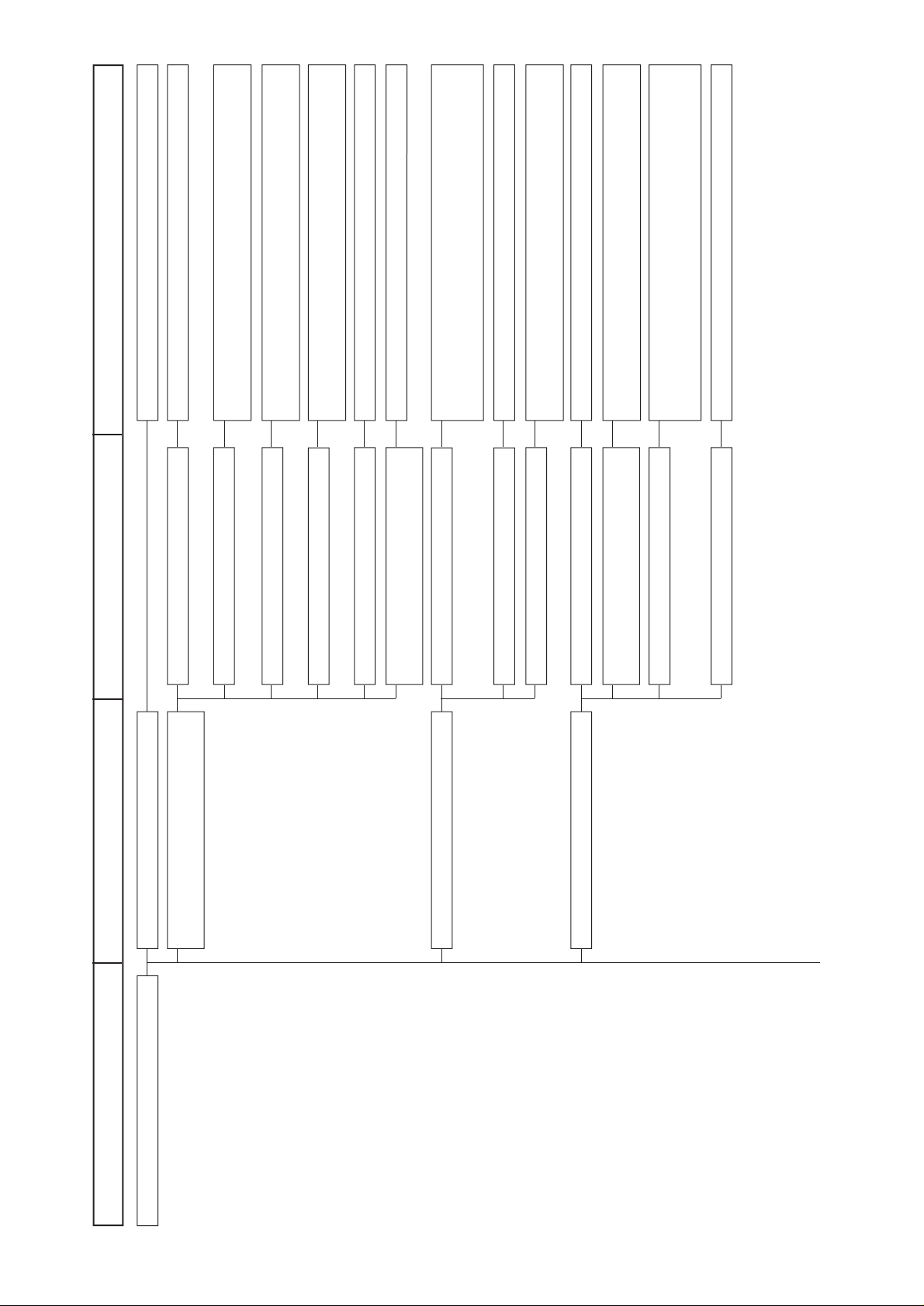
Use a thin needle if possible. KN or SPP needle is effective.
Finish the thread path.
Advance the hook timing to such an extent that stitch skipping
does not occur, and improve thread slipping.
Delay feed in terms of needle so that thread is pulled by feed
force.
Move arm thread guide to the right, and decrease thread supply
amount by the thread take-up.
Increase the stroke.
Use silicon.
Minimize the pressure. For some materials, it is effective to use
the micro-lifter screw and sew in the state that the presser foot is
Thread path is not smooth.
Hook timing is too late.
Feed timing is too early.
Stroke of the thread take-up is too large.
Stroke of the thread take-up is too small.
Material through which thread is hard to be
slided.
Presser foot pressure is too high.
slightly raised..
Polish with buff or the like to improve the slide.
Use the teflon presser foot or specially processed (teflon, etc.)
presser foot.
Replace it with gauge with small needle hole.
Use the presser foot with small recess on the sole or without
recess on it.
Replace the presser foot. Or, loosen the presser bar guide bracket
screw and correct the needle entry position and bend of presser
Finish of presser foot sole is bad.
Material is hard to be slided.
Needle hole of throat plate is too large.
Recess for thread on presser foot sole is
too large.
Parallelism of presser foot is defective.
foot when needle entry position is improper.
Replace the needle.
Top end of needle is blunt.
Thread tension (needle thread or bobbin
thread) is too high.
Presser foot is defective.
Fabric is floppy.
Troubles Cause (1) Cause (2) Checking orders and corrective measures
5. TROUBLES IN SEWING AND CORRECTIVE MEASURES
Puckering Needle is too thick.
−50 −
▼
To the next page
Page 54

Lower the height of feed dog (standard 0.8 mm), or increase the
pressure of the presser foot to protect it from jumping.
Sharpen the top ends of teeth with diamond file or the like, or
replace it with a new one.
Replace the feed dog with one with fine pitch.
Change the position of feed driving base pin, and tilt the feed
dog with its front up to make the puller effect.
Replace the feed dog.
Decrease the number of revolution.
Use a gauge having a small clearance between groove of throat
plate and moving direction of feed dog in the range that the feed
dog does not come in contact with the throat plate when the feed
dog is moving if the feed dog pitch is small.
Lower the height of feed dog (standard 0.8 mm), or increase the
pressure of the presser foot to protect it from jumping.
Height of feed dog is too high and jumping
of the feed dog occurs at high speed.
Abration of top ends of teeth of feed dog
Feed dog pitch is too coarse.
Tilt of feed dog is defective.
Parallelism of feed dog is defective.
Number of revolution is too high.
Others
Height of feed dog is too high.
Adjust the feed driving cam timing referring to [Adjusting feed
timing and dimensions of the feed base].
Adjust the feed driving cam to marker line (-).
Sharpen the top ends.
Use the feed dog with fine pitch.
Tilt the feed dog with its front down.
Locus of feed dog is defective.
Abration of top ends of teeth of feed dog
Feed dog pitch is to coarse.
Tilt of feed dog is defective.
Defective feed
From the previous page
Troubles Cause (1) Cause (2) Checking orders and corrective measures
Defective feed
▼
To the next page
Irregular stitches
−51 −
Page 55

Minimize the pressure. For some materials, it is effective to use
the micro-lifter screw and sew in the state that the presser foot is
slightly raised.
Polish with buff or the like to improve the slide.
Use the teflon presser foot, or specially processed (teflon, etc.)
presser foot.
Decrease the number of revolution.
Increase the tension of thread tension No. 2.
Balloon stitch or thread breakage is apt to occur if the stroke of
thread take-up spring is small since the released thread is not
pulled up enough. Adjust the stroke of thread take-up spring to a
rather large value.
If the tensin is too low, when the machine runs at high speed, the
spring cannot follow up and pulling-up of thread is deteriorated.
As a result, balloon stitch or thread breakage is apt to occur.
If the top end of thread take-up spring is opened, thread may be
caught with it when thread is slackened. Close the top end with
fingers when it is excessively opened.
The weak thread take-up spring of A type does not show the
effect enough for the thread of # 60 or more since the tension at
the end of motion does not become large. In this case, replace it
with the standard thread take-up spring (or thread tension).
Move the arm thread guide to the right to decrease the supplying
amount of thread by the thread take-up.
Presser foot pressure is too high.
Presser foot is defective.
Finish of presser foot sole is bad.
Material is hard to be slipped.
Number of revolution is high.
Stroke of thread take-up spring is small.
Thread tension is low.
Thread take-up spring is improperly
adjusted.
From the previous page
Troubles Cause (1) Cause (2) Checking orders and corrective measures
Tension is low.
Shape of thread take-up spring is improper.
Strength of thread take-up spring is weak.
Follow-up capability at high speed is
defective.
Stroke of thread take-up is large.
▼
To the next page
Balloon stitches
−52 −
Page 56

For cotton thread and spun thread, adjust the timing to the
standard, or slightly delay the timing.
For filament thread, adjust the timing to the standard, or slightly
advance the timing.
Increase the clearance to improve the slide of thread.
Properly adjust the amount of oil.
Replace the hook.
Finish the thread path.
Finish the thread path.
Correct threading.
Replace the bobbin or bobbin case.
Hook timing is too early.
Hook timing is too late.
Clearance between hook and bobbin case
holder is small.
Amount of oil in the hook is small.
Hook is defective (Thread is caught in the
hook.)
Thread path is not smooth.
There is a scratch in the thread path.
There is a burr in the thread path.
Bobbin thread is caught in the bobbin case
due to improper engagement of bobbin with
Adjust the tension or position of bobbin winder thread tension. In
addition, take care of uneven winding.
Replace the bobbin case.
Adjust the pressure of idle-prevention spring referring to the item
(7).
Correct the burr of scratched part, or replace the bobbin.
Slightly delay the feed timing. (Cotton thread and spun thread)
Or, advance the timing. (Filament thread)
Raise the heigt of feed dog.
bobbin case.
Bobbin thread is caught in the bobbin since
thread is improperly wound round the
bobbin.
Tension adjusting spring of bobbin case is
defective.
Bobbin thread in the bobbin case runs idle.
There is a scratch in the bobbin.
Feed timing is improper, or feed dog height
is low.
Places related to the hook are defective.
Thread path is defective
From the previous page
Troubles Cause (1) Cause (2) Checking orders and corrective measures
Bobbin or bobbin case is defective.
−53 −
Feed is defective.
▼
To the next page
Page 57
Adjust the clearance between presser bar guide bracket and lifting
plate. (A clearance of 0.8 to 1 mm should be provided when the
presser foot comes closely in contact with the lifting plate.)
Use the presser foot with the large recess on the sole.
Adjust the timing of thread tension disk rising referring to the
item (3-8).
Use the throat plate with large needle hole.
Replace the needle or the thread used.
Replace the needle.
Replace the needle.
Re-attach the needle. Replace the needle clamp screw. Defective
stitching is apt to occur when attaching the needle with its indented
part facing to this side.
Replace the needle.
Replace the needle.
Raise the height of the feed dog.
Corrrect the blade point of the hook or replace the hook.
Readjust the timing (advance the timing when needle thread loop
can be easily formed, and delay the timing when needle thread
loop is hard to be formed in accordance with the conditions of
fabric and thread.
Adjust the height of needle bar in terms of the blade point of the
hook to upper or lower.
Decrease the clearance between the blade point and the needle.
Turn thread around the needle, or use T-type needle bar thread
guide (B1418227T00).
Replace the hook with one with needle guard.
For SS : 1141355, For DS : 22890404
Presser foot is rising.
Presser foot is defective.
Recess for thread on the rear side of
presser foot is not provided, or small.
Presser foot does not work especially when
the pitch is large, or thick thread is used.
Thread tension disk is rising.
Thread tension is defective.
Needle hole of throat plate is small.
There is a burr on the top end of needle.
Needle is thin for thread used.
Needle is defective.
From the previous page
Troubles Cause (1) Cause (2) Checking orders and corrective measures
Needle is bent.
Attaching direction of needle is improper.
Or, it is not inserted until it will go no further.
Top of needle is blunt.
Needle is too thin for the thread used.
Feed force is weak.
Top end of needle is blunt, or worn out.
Needle is defective.
Places related to the hook
Hook timing is defective.
Height of needle bar is improper.
Clearance between blade point of hook and
needle is improper.
Loop formation is unstable. (When net
material or the like is used.)
There is no needle guard.
▼
To the next page
Stitch skipping
−54 −
Page 58

Decrease the tension. Use silicon.
Decrease the number of revolution.
Advance the feed timing.
Decrease the stroke.
Decrease the tension.
Adjust the clearance between presser bar guide bracket and lifting
plate.
Needle is bent at the thich section.
Stroke is large.
Tension is high.
Presser foot is rising.
Use the throat plate with small needle hole.
Use the presser foot with small recess on the sole, or without
recess.
Replace the presser foot, or loosen presser bar guide bracket
screw to adjust the bend of the presser foot.
Finish the thread path.
Finish the thread path.
Recheck threading to correct.
Properly adjust the tension.
Adjust so that thread between thread tension No. 1 and No. 2
does not run around.
Adjust the stroke.
Needle hole of throat plate is large.
Recess on the presser foot sole is large.
Parallelism of presser foot is defective.
Thread path is not smooth.
There is a scratch in the thread path.
There is a burr in the thread path.
The tension is too high or too low.
Tension of thread tension No. 1 is too low.
The stroke is too large or too small.
Adjust the tension.
In case of A type thread tension, replace the spring with standard
one. (In case of thick thread of #60 or more)
The tension is too high or too low.
Selection of the spring for the kind of thread
is improper.
Needle thread tension is too high.
Number of revolution is too high.
Feed timing is defective. (Needle bend)
Thread take-up spring is improperly
adjusted.
Cloth is floppy.
From the previous page
Troubles Cause (1) Cause (2) Checking orders and corrective measures
Thread path is defective (including throat
plate and presser foot).
Needle thread breakage
−55 −
Needle thread tension is improper.
Thread take-up spring is improperly
adjusted.
▼
To the next page
Page 59

Replace the needle.
Replace the needle.
Replace the needle.
Reattach the needle. Defective stitching is apt to occur when
attaching the needle with its indented part facing to this side.
Needle is bent.
There is a scratch on the needle.
Top end of the needle is blunt.
Attaching direction of the needle is
improper.
Replace the needle.
Use the ball-point needle.
Replace the needle.
Needle is too thin or too thick for the thread
used.
Top end of the needle is too sharp.
There are scratches on the hook thread
Correct the hook blade point, or replace the hook.
Increase the clearance to improve the slide of thread.
path.
Blade point of the hook is blunt, or worn
out.
Clearance between hook and bobbin case
holder is small.
Properly adjust the amount of oil in the hook.
Replace the needle.
Amount of oil in the hook is small.
There are scratches on the hook thread
Attach the needle with its indented part facing slightly to anti-
operator’s side (approx. 10˚) from the exact lateral side.
Adjust the thread take-up spring so that thread is not fed from
the thread tension disk before the thread take-up spring moves
to the end of stroke.
(It is effective to adjust the spring pressure to lower, and the stroke
to larger than the specified values.)
Turn thread around the needle, or change the needle bar thread
path.
Attching direction of the needle is improper.
Thread take-up spring is improperly
adjusted.
guide to T-type one (B1418227T00).
Needle is defective.
Places related to the hook are defective.
From the previous page
Troubles Cause (1) Cause (2) Checking orders and corrective measures
−56 −
Places related to the hook are defective.
Attaching direction of the needle is
improper.
Thread breaks when reverse feed stitching
or back-tack stitching is performed.
▼
To the next page
Page 60

Adjust the hook in the state that the timing is earlier by 0.2 mm
than the lower marker line of needle bar.
Or, change the needle bar to needle bar of 22886907. Interval of
the marker lines of needle bar of 22886907 is narrower by o.2
mm than that of the standard.
Adjust the stroke.
Adjust the tension.
In case of A type thread tension, replace the spring with the
standard one. (In case of thick thread of #60 or more)
Same adjustment as [Thread breaks when performing reverse
If the hook timing is delayed, needle thread
loop becomes too big and is deformed. As
a result, thread breakage occurs since the
blade point catches thread twice.
Stroke is too large or too small.
Tension is too high or too low.
Selection of the spring is improper for the
kind of thread.
feed stitching or back-tack stitching]
Same cause as [Thread breaks when
performing reverse feed stitching or back-
Adjust so that needle drops in the center of the hole.
tack stitching]
Raise the needle bar.
Decrease the tension.
Replace the needle.
Replace the needle.
Use a thick needle. Use the double-step needle in case of KN
Needle is bent.
Top end of the needle is blunt.
Needle is too thin.
needle (one step needle).
Use a short needle. Or, use a needle with long shank. (DAX1)
Decrease the number of revolution.
Needle is too long.
Hook timing is delayed.
Thread take-up spring is improperly
adjusted.
Same cause as [Thread breaks when
performing reverse feed stitching or back-
From the previous page
Troubles Cause (1) Cause (2) Checking orders and corrective measures
Thread breaks when performing idle stitching
or jump stitching.
tack stitching]
Position of the knife thread guide is
improper.
Needle bar is positioned low.
Needle thread tension is too high.
Needle is defective.
Uneven stitches
−57 −
Number of revolution is too high.
▼
To the next page
Page 61

Replace the feed dog.
Correct the installation.
Remove the play in the state that the feed driving base pin and
the feed rocker base pin are slightly pressed.
Readjust the position of presser bar guide bracket.
Replace the presser foot. Or, loosen the presser bar guide bracket
screw and adjust the bend of presser foot.
Parallelism of feed dog is defective.
Feed dog is slantly installed.
There is a lateral play in the feed base.
Presser foot is rising.
Parallelism of presser foot is defective.
Increase the presser foot pressure.
Correct the threading.
Try to use B1418227T00 or B1418552A00.
Use silicon.
Use a thin needle that is as thin as possible.
Replace the needle.
Presser foot pressure is too low.
Threading of needle thread is wrong.
Needle bar thread guide is defective.
Heat of needle is high.
Needle is too thick.
Top end of needle is blunt.
Use the ball-point needle (KN, S, J, B, U, Y, etc.)
Shape of the top end of needle is defective.
Decrease the number of revolution.
Use the throat plate with large needle hole.
Decrease the pressure as low as possible.
Lower the position as low as possible.
(Kind of needle)
Needle hole of throat plate is small.
Presser foot pressure is too high.
Feed dog is positioned high.
Keep the humidity at approximately 65% to protect the needle
from heat and charge friction.
Make the pitch as large as possible.
Use the hook with needle guard corresponding to the needle
equivalent to #11.
For SS : 11141355, for DS : 22890404
Defective feed
Presser foot is defective.
Threading is improper.
From the previous page
Troubles Cause (1) Cause (2) Checking orders and corrective measures
Needle is defective.
Broken material
−58 −
Number of revolution is too high.
Cloth is excessively tensed.
Humidity of guide is too low.
Feed pitch is too small.
Bobbin is damaged by the bend of needle.
Bobbin is damaged.
Page 62

Properly adjust the amount of oil.
Replace the hook, or correct the thread path.
Replace the bobbin or bobbin case.
Amount of oil in the hook is too many or
too small.
Defective hook (thread is caught in the
hook, thread path is defective, etc.)
Bobbin thread is caught in the bobbin case
Adjust the tension or position of the bobbin winder thread tension.
In addition, take care of uneven winding.
Replace the bobbin case.
due to the defective engagement of bobbin
with bobbin case.
Bobbin thread is caught in the bobbin case
due to defective thread winding round the
bobbin.
Tension adjusting spring of bobbin case is
defective.
Adjust the tension of idle-prevention spring referring to the item
7.
Refer to the item 7. Reverse revolution of the bobbin improves
irregular stitches.
Increase the tension.
Adjust the stroke of the thread take-up spring.
Adjust the tension.
Finish the thread path.
Finish the thread path.
Correct the threading.
Replace it with gauge with small needle hole.
Use the presser foot with small recess on the sole or without
recess.
Replace the presser foot. Or, when the needle entry position is
Bobbin thread in the bobbin case runs idle.
Setting direction of bobbin into bobbin case
is improper.
Stroke of thread take-up spring is large or
small.
The tension is high or low.
Thread path is not smooth.
There is a scratch in the thread path.
There is a burr in the thread path.
Needle hole of throat plate is too large.
Recess for thread on the presser foot sole
is too large.
Parallelism of the presser foot is defective.
improper, loosen the presser bar guide brackect screw and correct
the needle entry position or the bend of the presser foot.
Adjust the clearance between the presser bar guide bracket and
the lifting plate.
Check the looseness in the feed driving section and remove the
looseness.
Move the arm thread guide to the right and decrease the supply
of thread from the thread take-up.
Use D1113126WA0.
Presser foot is rising.
Pitch changes according to the number of
revolution and irregular stitches occur.
Places related to th hook are defective.
Bobbin or bobbin case is defective.
Troubles Cause (1) Cause (2) Checking orders and corrective measures
Irregular stitches
Needle thread or bobbin thread tension is
too low.
Thread take-up spring is improperly
adjusted.
−59 −
Thread path is defective.
Cloth is floppy.
Looseness in feed movement direction
Stroke of the thread take-up is large.
There is no resistance in the thread guide
rod.
Page 63

6. BOBBIN CASE WITH IDLE-PREVENTION SPRING
For the DDL-9000 series, bobbin case with idle-prevention spring is used.
Adjust the tension of the idle-prevention spring in the following procedure.
When the bobbin runs idle Increase the tension of the idle-prevention spring.
When the thread is not well tightened Decrease the tension of the idle-prevention spring.
* Adjusting the idle-prevention spring
1) Insert an old sewing needle or the like into the bobbin as shown in the illustration, and remove the spring in a
manner of just lifting it.
(Prevent the spring from jumping out with your thumb.)
2) To change the pressure of the spring, change the height of arched section of the spring.
(Take care so that the free end pf the spring does not rise from the bobbin case.)
3) First, set the ear (1), insert a sewing needle into the bobbin, and set the ear (2) in the state that the central part
of the spring is raised.
(Part No. of bobbin case spring : D1837555B0B)
To change
the height
▼
▼
Ear
(2)
0.3 ± 0.2
(1)
1) 2) 3)
* When using the bobbin case with idle-prevention spring, be sure to set it in the direction of winding as shown in
the illustration.
Rotation of bobbin
(Irregular stitches at high or low speed)
When the thread is excessively tightened at low speed Adjust the tension of bobbin thread and that of
Rotation of bobbin
When the bobbin case
without idle-prevention
spring is used.
▼
idle-prevention spring to rather higher.
When the thread is insufficiently tightened at low spped Adjust the tension of bobbin thread and that of
* When idle running of bobbin or irregular stitch at high or low speed makes troubles, it is effective to use the
bobbin case with idle-prevention spring.
−60 −
▼
idle-prevention spring to rather lower.
Page 64

R
INTERNATIONAL SALES H.Q.
8-2-1, KOKURYO-CHO,
CHOFU-SHI, TOKYO 182-8655, JAPAN
PHONE : (81)3-3430-4001 to 4005
FAX : (81)3-3430-4909 • 4914 • 4984
TELEX : J22967
Copyright (C) 1999 JUKI CORPORATION.
All rights reserved throughout the world.
Please do not hesitate to contact our distributors or agents in your area for further information when necessary.
*The description covered in this engineer's manual is subject to change for improvement of the
commodity without notice.
99 · 08 Printed in Japan (E)
 Loading...