

Page 1

ENGLISH
DDL-8700A-7
INSTRUCTION MANUAL
i
Page 2

CONTENTS
!
. SPECIFICATIONS ..................................................................................... 1
@
. SET-UP ...................................................................................................... 3
1. Installation .................................................................................................................. 3
2. Installing the pedal sensor ....................................................................................... 4
3. Installing the power switch ....................................................................................... 4
4. Attaching the connecting rod ................................................................................... 6
5. Winding the bobbin thread ....................................................................................... 7
6. Adjusting the height of the knee lifter ..................................................................... 8
7. Installing the thread stand ........................................................................................ 8
8. Lubrication ................................................................................................................. 9
9. Adjusting the amount of oil (oil splashes) .............................................................. 9
10. Attaching the needle ...............................................................................................11
11. Setting the bobbin into the bobbin case ............................................................. 12
12. Adjusting the stitch length .................................................................................... 12
13. Presser foot pressure ............................................................................................ 12
14. Hand lifter ............................................................................................................... 12
15. Adjusting the height of the presser bar ............................................................... 13
16. Threading the machine head ................................................................................ 13
17. Thread tension ....................................................................................................... 14
18. Thread take-up spring ........................................................................................... 14
19. Adjusting the thread take-up stroke .................................................................... 14
20. Needle-to-hook relationship ................................................................................. 15
21. Height of the feed dog ........................................................................................... 15
22. Tilt of the feed dog ................................................................................................. 16
23. Adjusting the feed timing ...................................................................................... 16
24. Cunter knife ............................................................................................................ 17
25. Pedal pressure and pedal stroke ......................................................................... 17
26. Adjustment of the pedal ........................................................................................ 18
#
. FOR THE OPERATOR ............................................................................ 19
1. Operating procedure of the sewing machine ........................................................ 19
2. Built-in panel of the machine head ........................................................................ 21
3. Operating procedure of the sewing pattern .......................................................... 22
4. One-touch setting .................................................................................................... 24
5. Production support function .................................................................................. 25
6. Setting of functions ................................................................................................. 28
7. Function setting list ................................................................................................. 29
8. Detailed explanation of selection of functions ..................................................... 33
9. Automatic compensation of neutral point of the pedal sensor ........................... 43
10. Selection of the pedal specications ................................................................... 43
i
Page 3

11. Setting of the auto lifter function ......................................................................... 44
12. Selecting procedure of the key-lock function ..................................................... 45
13. Removing the rear cover ....................................................................................... 46
14. Connection of the pedal of standing-work machine .......................................... 48
15. External input / output connector ........................................................................ 48
16. Connection of the material end sensor ............................................................... 49
17. Initialization of the setting data ............................................................................ 50
$
. MAINTENANCE ...................................................................................... 51
1. Replacing the fuse ................................................................................................... 51
2. Adjusting the machine head ................................................................................... 52
3. Connector layout drawing ...................................................................................... 53
4. Error codes ............................................................................................................... 54
ii
Page 4
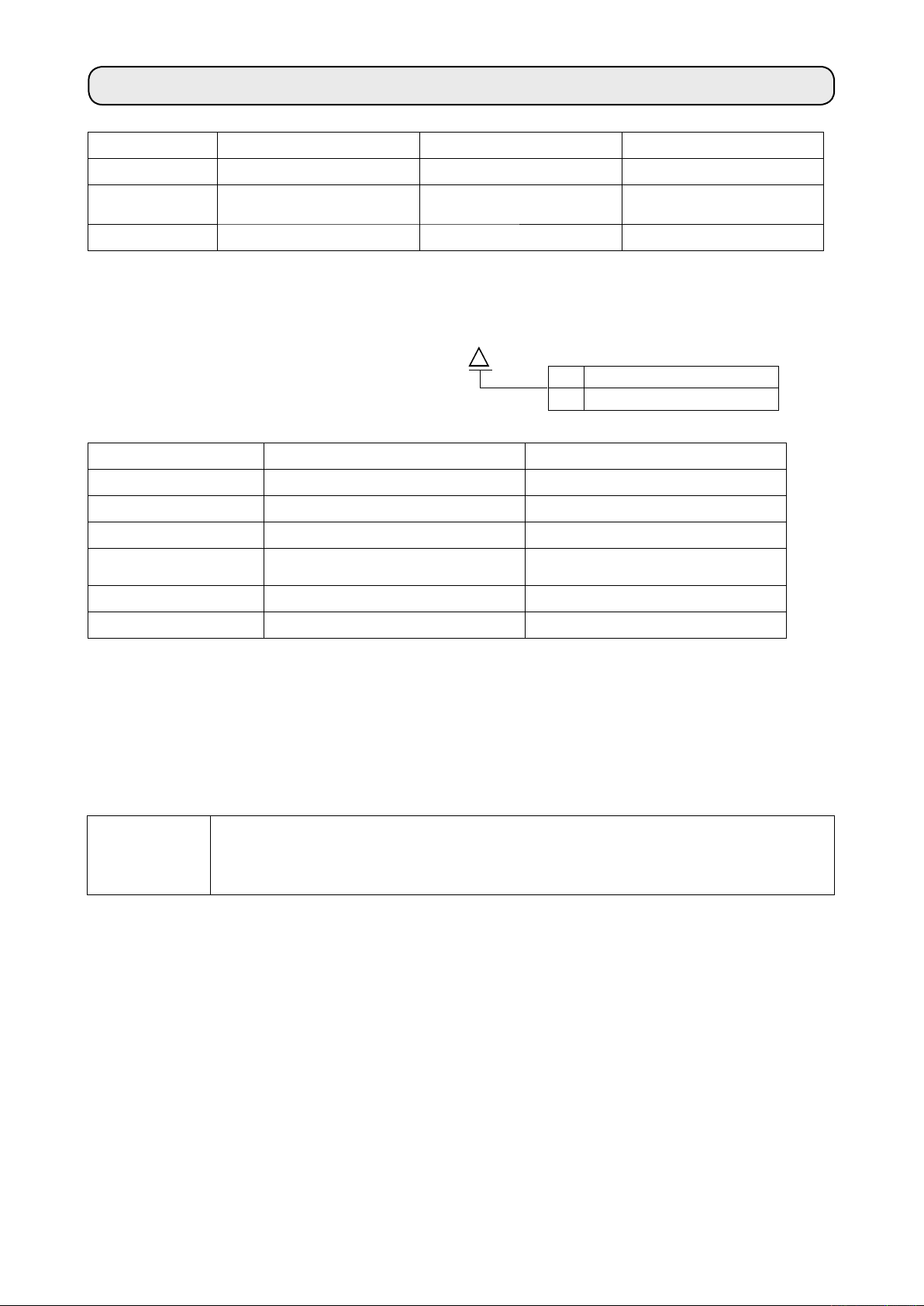
!
. SPECIFICATIONS
Supply voltage Single phase 100 to 120V 3-phase 200 to 240V Single phase 220 to 240V
Frequency 50Hz/60Hz 50Hz/60Hz 50Hz/60Hz
ing environ-
Operat
ment
Input 2
Temperature : 5 to 35˚C
Hum
idity 35 - 85 % or less
10VA 210VA 210VA
Temperature : 5 to 35˚C
Humidity 35 - 85 % or less
Temperature : 5 to 35˚C
Humidity 35 - 85 % or less
DDL-8700A - 7
S :
Medium-weight materials
H : Heavy-weight materials
DDL-8700AS-7 DDL-8700AH-7
Max. sewing speed 5,000 sti/min 4,000 sti/min
Thread trimming speed 300 sti/min 300 sti/min
Stitch length
Presser foot l
(by knee l
Needle
Lubricating oil JUKI MACHINE OIL #7 JUKI MACHINE OIL #7
• The sewing speed will vary depending on the sewing conditions.
• The sewing speed preset at the time of shipping ......AS-7 : 4,000sti/min.
...... AH-7 : 3,500sti/min.
1
: Needle used depends on the destination.
*
*1
ift
ifter)
DB x 1 (#14) #9 to 18 DB x 1 (#21) #20 to 23
4mm 5mm
13 mm 13 mm
Noise
- Equivalent continuous emission sound pressure level (LpA) at the workstation :
A-weighted value of 79.5 dB; (Includes KpA = 2.5 dB); according to ISO 10821- C.6.2 -ISO
11204 GR2 at 4,000 sti/min.
– 1 –
Page 5
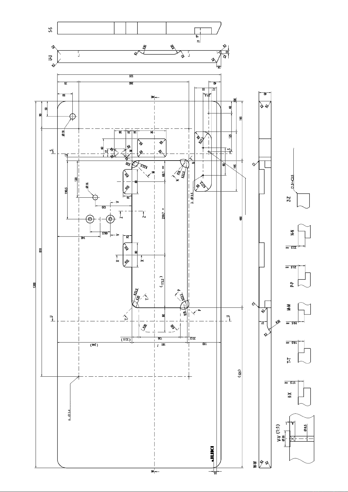
depth 10
DRAWING OF TABLE
(Hinge side only)
2-ø3.4 bottom surface, depth 10
bottom surface, depth 20
– 2 –
Page 6
@
. SET-UP
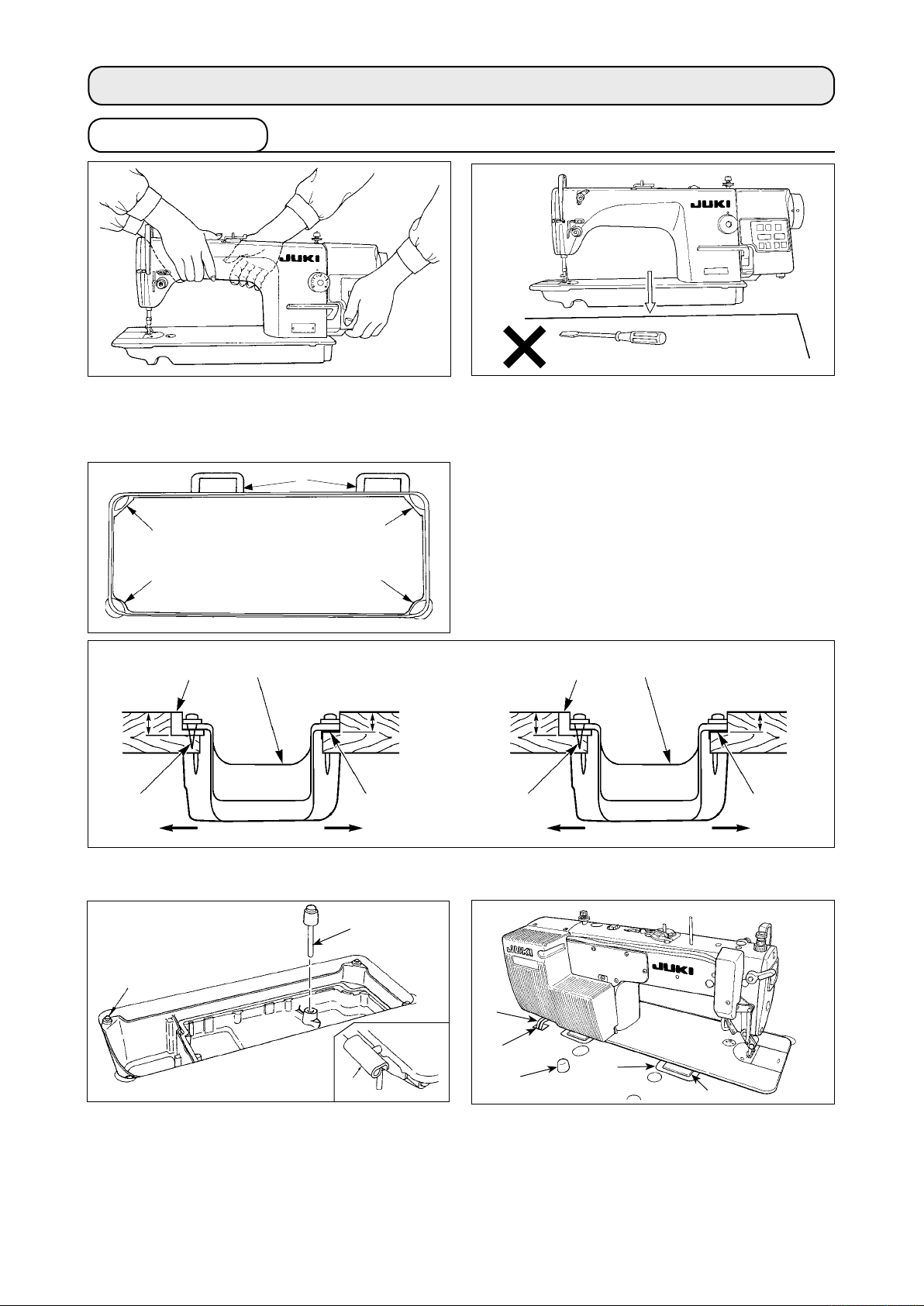
1. Installation
1) Carry the sewing machine with two persons as
shown in the gure above.
(Caution) Do not hold the handwheel.
8
3
1
Needle bar side
1
23.5mm
2
4
A
B
3
1
19.5mm
3
2) Do not put protruding articles such as the screw-
driver and the like at the location where the sew-
ing machine is placed.
3) The under cover should rest on the four cor-
ners of the mach
ine table groove. Mount rubber
hinge seat 8 on the table and x it on the table
ith a nail.
w
ontrol box side
C
1
23mm
2
4
19.5mm
3
A
B
4) Fix two rubber seats 1 on side A (operator’s s
on side B (h
3
9
5) Fit knee lifter pressing rod 6. F
to table rubber h
6)
Securely attach head support rod !0 to the table unt
(Caution) Be sure to install the machine head support bar supplied with the unit.
inged side) using a rubber-based adhesive. Then place under cover 4 on the xed seats.
6
7
it hinge 7 into the opening in the machine bed, and t the machine head
inge 8 before plac
ing the machine head on cushions 9 on the four corners.
ide) using nails 2 as
!1
!2
!0
il it goes no further.
illustrated above. Fix two cushion seats
8
7) Draw out cable !1 of the control box through cable draw-out hole !2 to route
sewing machine table.
– 3 –
7
it to the underside of the
Page 7

2. Installing the pedal sensor
1
1
The explanation applies to the case the
pedal sensor is installed on the table for
the DDL-8700A-7.
1) Install the pedal sensor on the table
by means of mounting bolt asm. 1
supplied with the unit. At this time,
insert the nut and washer supplied
with the unit as accessories as shown
in the gure so that the control box is
securely xed.
2) After the completion of installation of
the pedal sensor on the table, place
the sewing machine head on the
table.
washer
WARNING :
• To protect against personal injury resulting from abrupt start of the sewing machine, be sure to
turn the power OFF, unplug the machine and wait for ve minutes or more before installing the
pedal sensor.
•
To prevent damage of device caused by maloperation and wrong specifications, be sure to
connect all the corresponding connectors to the specied places. (If any of the connectors is
inserted into a wrong connector, not only the device corresponding to the connector can break
but also it can start abruptly, inviting the risk of personal injury.)
•
To prevent personal injury caused by maloperation, be sure to lock the connector with lock.
• As for the details of handling respective devices, read carefully the Instruction Manuals supplied
with the devices before handling the devices.
3. Installing the power switch
Plain
Spring
washer
Hexagonal
nat
(Caution) Do not insert the power plug into the plug receptacle.
1
1) Remove screw 1 on the side face of the power
switch cover to open the power switch cover.
– 4 –
2
2)
Pass AC input cord 2 coming from the control box
3
through the rear face of the power switch. Bundle
the cord with cable clip band 3 to secure it.
Page 8
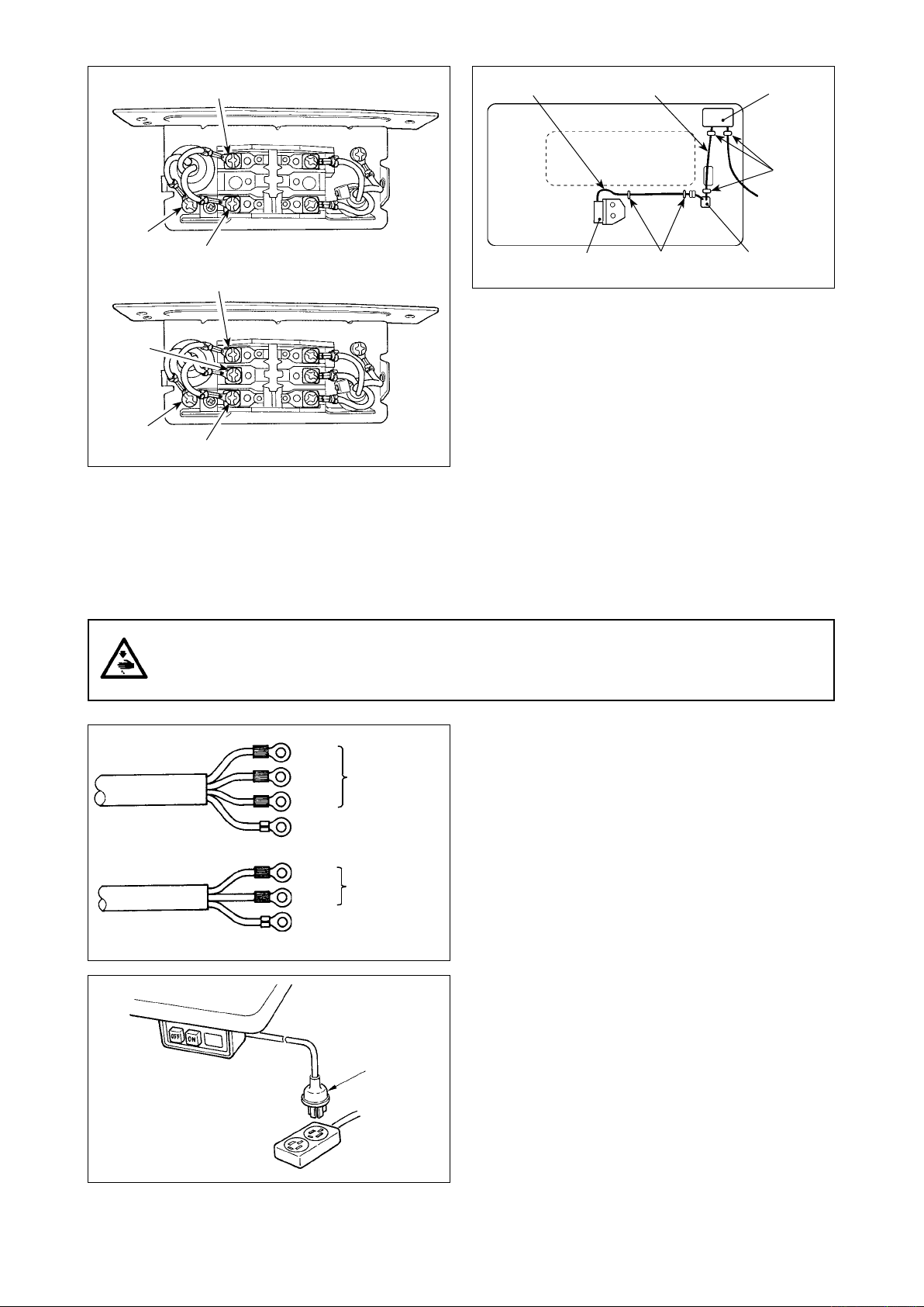
1ø 100V-120V
220V-240V
White
Pedal sensor cable
AC cable
Power switch
Staples
(large)
Green/
Yellow
3ø 200V-240V
Black
Green/
Yellow
Black
White
R
ed
3) Securely x the terminals of the AC input cord
by tightening the screws at the specied loca-
tions.
4) Close the power switch cover. Tighten screw 1
on the side face of the power switch cover.
WARNING :
1. Be sure to attach the ground wire (green/yellow) to the specied location (on the ground side).
2. Take care not to allow terminals to come in contact with each other.
3. When closing the power switch cover, take care not to allow the cord to be caught under it.
C
Pedal sensor
Staples (small)
able draw-out
hole
5) Firstly attach the staple supplied with the unit as
accessories to the cable. Then, hammer them
into the sewing machine table.
At this time, attach the staples at the locations
shown in the gure.
3ø 200V-240V
1ø 100V-120V
220V-240V
Black
C 200V-240V
ed
A
AC 100V-120V
AC 220V-240V
3
R
White
Green / Yellow
(ground wire)
Black
White
Green / Yellow
(ground wire)
6) Connect the power cord to the power plug.
As shown in the gure, connect the white and black
(and red) wires to the power supply side and the
green/yellow one to the grounding side.
(Caution) 1. Be sure to prepare the power plug
3
which conforms to the safety stan-
dard.
2.
Be sure to connect the ground lead
(green/yellow) to the grounding side.
7) Check that the power switch is in the OFF state.
Then, insert the power plug coming from the power
switch into the plug receptacle.
(Caution) In prior to the connection of the power
plug, re-check the supply voltage speci-
cation indicated on the power box.
– 5 –
Page 9
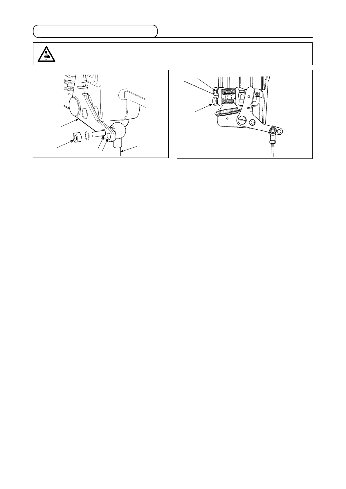
4. Attaching the connecting rod
WARNING :
To protect against possible personal injury due to abrupt start of the machine, be sure to start the
following work after turning the power off and a lapse of 5 minutes or more.
2
5
4
3
B
A
1) Fix connecting rod 1 to
installing hole B of
1
pedal lever 2 with nut 3.
2)
Installing connecting rod 1 to
w
ill lengthen the pedal depressing stroke, and
installing hole A
the pedal operation at a medium speed will be
easier.
3) The pressure increases as you turn reverse de-
pressing regulator screw 4
in, and decreases as
you turn the screw out.
(Caution) 1. If the screw is excessively loosened,
the spring will come off.
Loosen the screw to such an extent
that the top of the screw can be observed from the case.
2.
W hen eve r y ou have adjusted the
screw, be sure to secure the screw by
tightening metal nut 5 to prevent the
screw from loosening.
– 6 –
Page 10
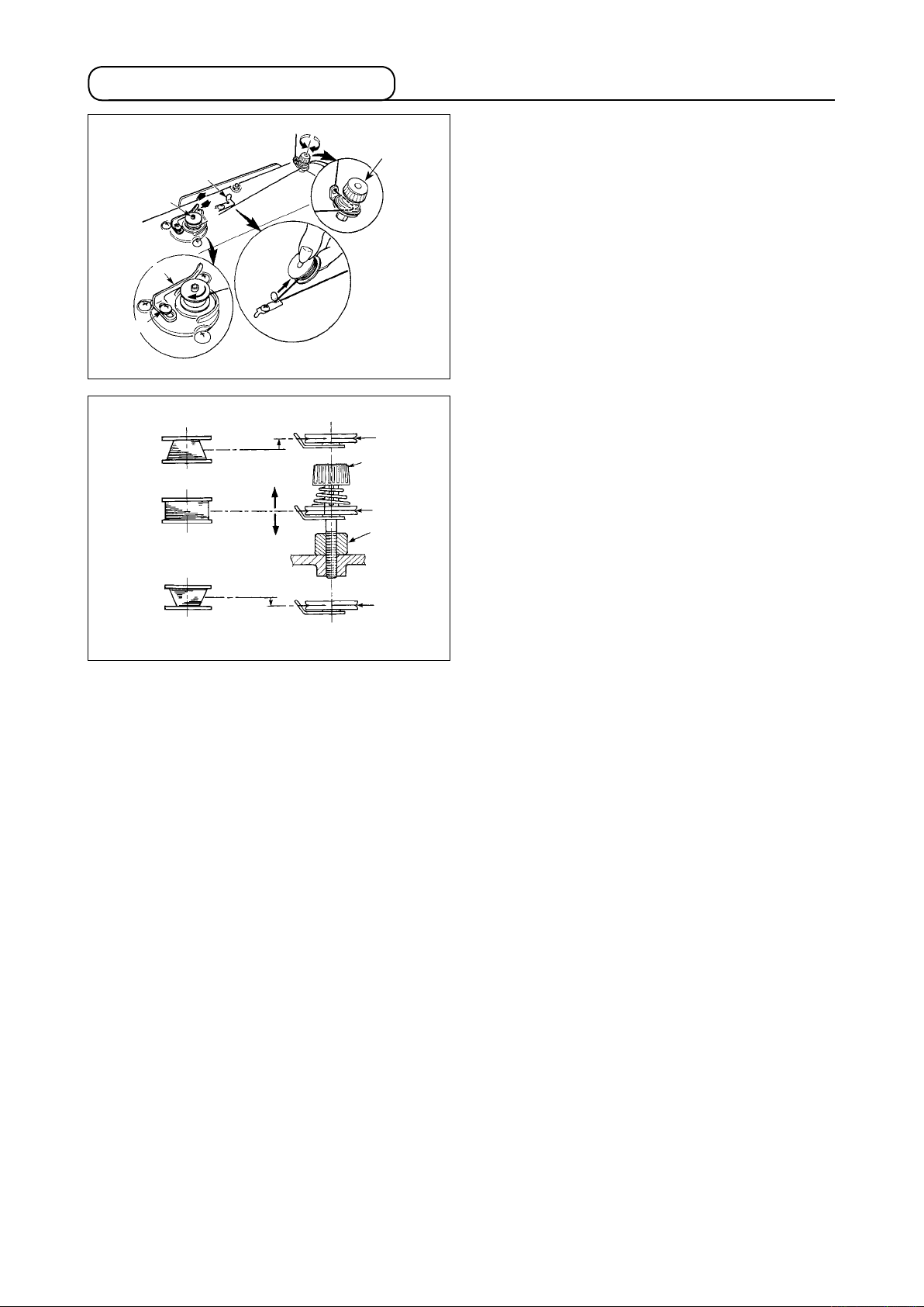
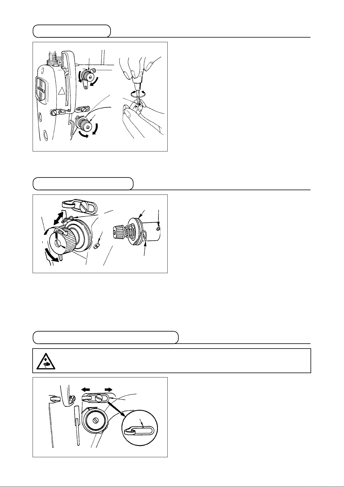
5. Winding the bobbin thread
3
B
1
2
4
A
C
D
E
7
5
6
6
6
8
1) Insert the bobbin deep into the bobbin winder
spindle 1 unt
il it will go no further.
2) Pass the bobbin thread pulled out from the
spool rested on the right side of the thread stand
following the order as shown in the gure on the
left.
Then, wind clockwise the end of the bobbin
thread on the bobbin several times.
(In case of the aluminum bobbin, after winding
clockwise the end of the bobbin thread, wind
counterclockwise the thread coming from the
bobbin thread tension several times to wind the
bobbin thread with ease.)
3) Press the bobbin winder trip latch 2
direction of A and start the sew
in the
ing machine.
The bobbin rotates in the direction of C and the
bobb
in thread is wound up. The bobbin winder
spindle 1 automat
ically as soon as the winding
is nished.
4) Remove the bobbin and cut the bobbin thread
with the thread cut retainer 3.
5) When adjusting the winding amount of the bob-
bin thread, loosen setscrew 4 and move bobbin
winding lever 2 to the direction of A or B. Then
tighten setscrew 4.
To the direction of A : Decrease
To the direction of B : Increase
6) In case that the bobbin thread is not wound evenly on the bobbin, remove the handwheel, loosen screw
and adjust the he
5
•
It is the standard that the center of the bobbin is as high as the center of thread tension disk 6.
• Adjust the position of thread tension disk 6 to the d
ight of bobbin thread tension 8.
irection of D when the winding amount of the bobbin
thread on the lower part of the bobbin is excessive and to the direction E when the winding amount of
the bobbin thread on the upper part of the bobbin is excessive.
After the adjustment, tighten screw 5.
7) To adjust the tension of the bobbin winder, turn the thread tension nut 7.
(Caution)
1. When winding the bobbin thread, start the winding in the state that the thread between the bobbin
and thread tension disk 6 is tense.
2. When winding the bobbin thread in the state that sewing is not performed, remove the needle thread
from the thread path of thread take-up and remove the bobbin from the hook.
3. There is the possibility that the thread pulled out from the thread stand is loosened due to the inu-
ence (direction) of the wind and may be entangled in the handwheel. Be careful of the direction of
the wind.
– 7 –
Page 11
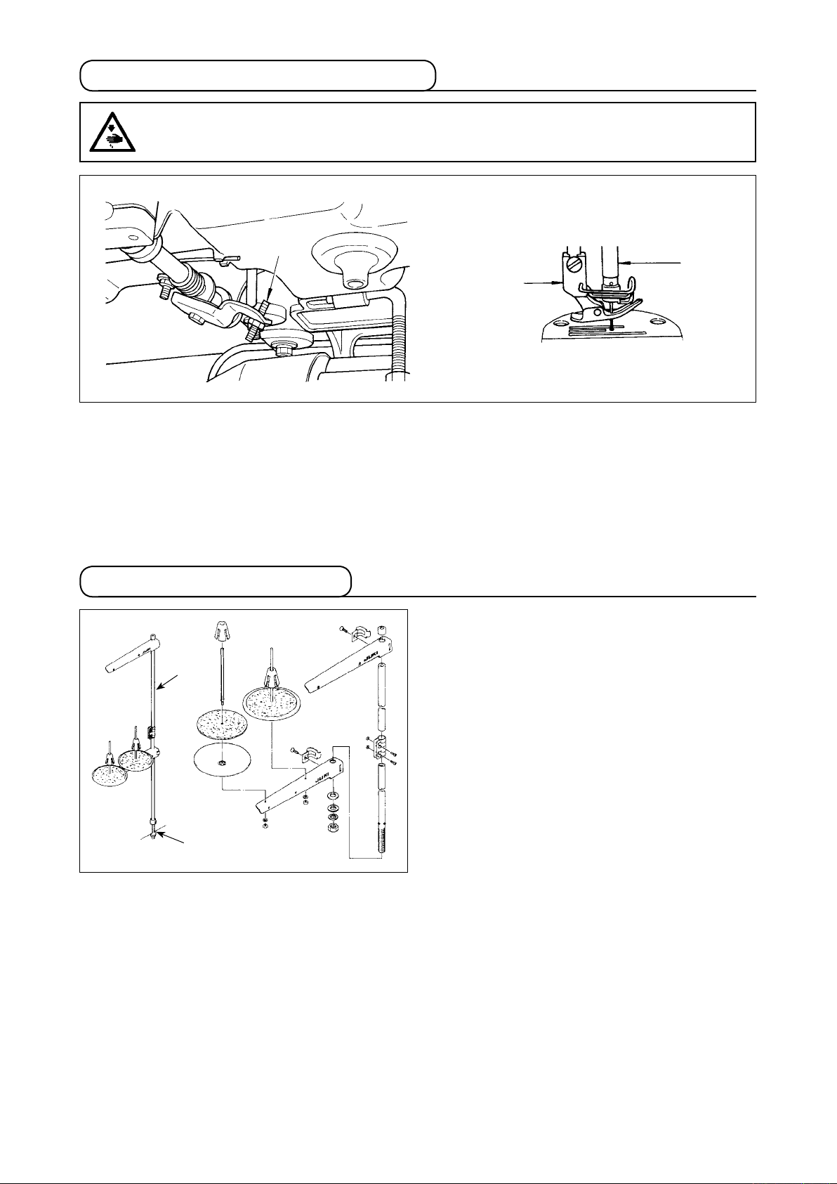
6. Adjusting the height of the knee lifter
WARNING :
Be sure to turn the power OFF before the following work in order to prevent personal injury due to
unintentional starting of the sewing machine.
1
2
3
1) The standard height of the presser foot lifted using the knee lifter is 10 mm.
2) You can adjust the presser foot lift up to 13 mm using knee lifter adjust screw 1.
3) When you have adjusted the presser foot lift to over 10 mm, be sure that the bottom end of needle bar
in its lowest position does not hit presser foot 3.
2
7. Installing the thread stand
2
1
1) Assemble the thread stand unit, and insert it in
the hole in the machine table.
2) Tighten nut 1.
3) For ceiling wiring, pass the power cord through
spool rest rod 2.
– 8 –
Page 12
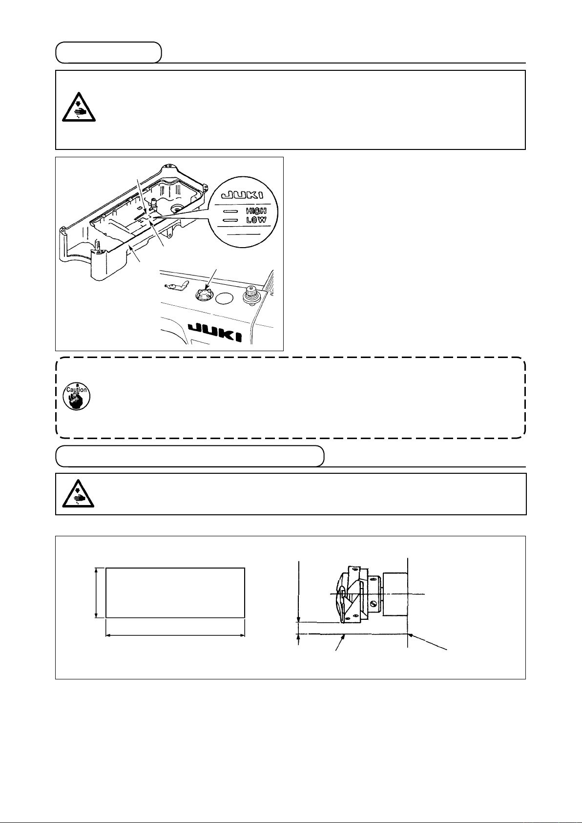
8. Lubrication
WARNING :
1. Do not connect the power plug until the lubrication has been completed so as to prevent
accidents due to abrupt start of the sewing machine,
2.
To prevent the occurrence of an inammation or rash, immediately wash the related portions if
oil adheres to your eyes or other parts of your body.
3.
If oil is mistakenly swallowed, diarrhea or vomitting may occur. Put oil in a place where children
cannot reach.
A
1
B
2
1) Before starting the sewing machine, ll oil pan
with JUKI MACHINE OIL #7 up to HIGH mark
1
.
A
2)
When the oil level lowers below LOW mark B,
rell the oil pan with the specied oil.
3) When you operate the machine after lubrica-
tion, you will see splashing oil through oil sight
window 2
if the lubrication is adequate.
4) Note that the amount of the splashing oil is un-
related to the amount of the lubr
icating oil.
1. When you use a new sewing machine or a sewing machine after an extended period of dis-
use, use the sewing machine after performing break-in at 2,000 sti/min or less.
2. For the oil for hook lubrication, purchase JUKI NEW DEFRIX OIL No. 1 (Part No. : MD-
FRX1600C0) or JUKI MACHINE OIL #7 (Part No. : MML007600CA).
3. Be sure to lubricate clean oil.
9. Adjusting the amount of oil (oil splashes)
WARNING :
Be extremely careful about the operation of the machine since the amount of oil has to be checked
by turning the hook at a high speed.
(1) Conrmation of the amount of oil in the hook
Amount of oil (oil splashes) conrmation paper
1
25 mm
70 mm
Position to conrm the amount of oil (oil splashes)
2
3 - 10 mm
Oil splashes conrmation paper
Closely t the paper against the wall
surface of the bed.
* When carrying out the procedure described below in 2, remove the slide plate and take extreme caution
not to allow your ngers to come in contact with the hook.
1) If the machine has not been sufciently warmed up for operation, make the machine run idle for approxi-
mately three minutes. (Moderate intermittent operation)
2) Place the amount of oil (oil spots) conrmation paper under the hook immediately after the machine
stops running.
3) Conrm the height of the oil surface in the oil reservoir is within the range between “HIGH” and “LOW”.
4) Conrmation of the amount of oil should be completed in ve seconds. (Check the period of time with a
watch.)
– 9 –
Page 13
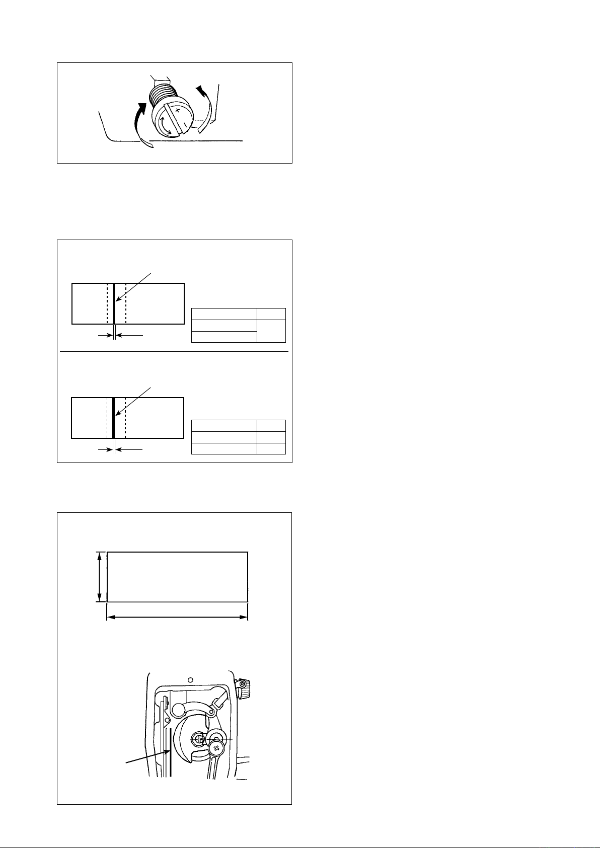
(2) Adjusting the amount of oil (oil spots) in the hook
1) Turning the oil amount adjustment screw attached
on the hook driving shaft front bushing in the “+”
direction (in direction A) w
oil (oil spots) in the hook, or in the “–” direction (in
d
B
A
irection B) w
2) After the amount of oil in the hook has been prop-
erly adjusted w
make the sewing machine run idle for approximately
30 seconds to check the amount of oil in the hook.
(3) Sample showing the appropriate amount of oil in the hook
ill increase the amount of
ill decrease it.
ith the oil amount adjustment screw,
Appropriate amount of oil (small)
Splashes of oil from the hook
should be nely adjusted in accordance with sewing
processes.
Be careful not to excessively increase/decrease the
amount of oil in the hook. (If the amount of oil is too
1) The amount of oil shown in the samples on the left
* mm
DDL-8700AS-7
DDL-8700AH-7
* mm
1mm
small, the hook will be seized (the hook will be hot).
If the amount of oil is too much, the sewing product
may be stained with oil.)
Appropriate amount of oil (large)
Splashes of oil from the hook
2) Adjust the amount of oil in the hook so that the
oil amount (oil splashes) should not change while
checking the oil amount three times (on the three
sheets of paper).
* mm
* mm
DDL-8700AS-7
DDL-8700
AH-7
2mm
3mm
(4) Conrmation of the amount of oil supplied to the face plate parts
Amount of oil (oil splashes) conrmation paper
1
25 mm
70 mm
Position to conrm the amount of oil
2
(oil splashes)
Oil splashes
conrmation paper
* When carrying out the work described below in
2), remove the face plate and take extreme cau-
tion not to allow your ngers to come in contact
with the thread take-up lever.
1) If the machine has not been sufciently warmed
up for operation, make the machine run idle for
approximately three minutes. (Moderate inter-
mittent operation)
2) Place the amount of oil (oil spots) conrmation
paper under the hook immediately after the ma-
chine stops running.
3) Conrm the height of the oil surface in the oil
reservoir is within the range between “HIGH”
and “LOW”.
4) The time required for the conrmation of the
amount of oil (oil splashes) should be completed
in ten seconds. (Measure the period of time with
a watch.)
– 10 –
Page 14
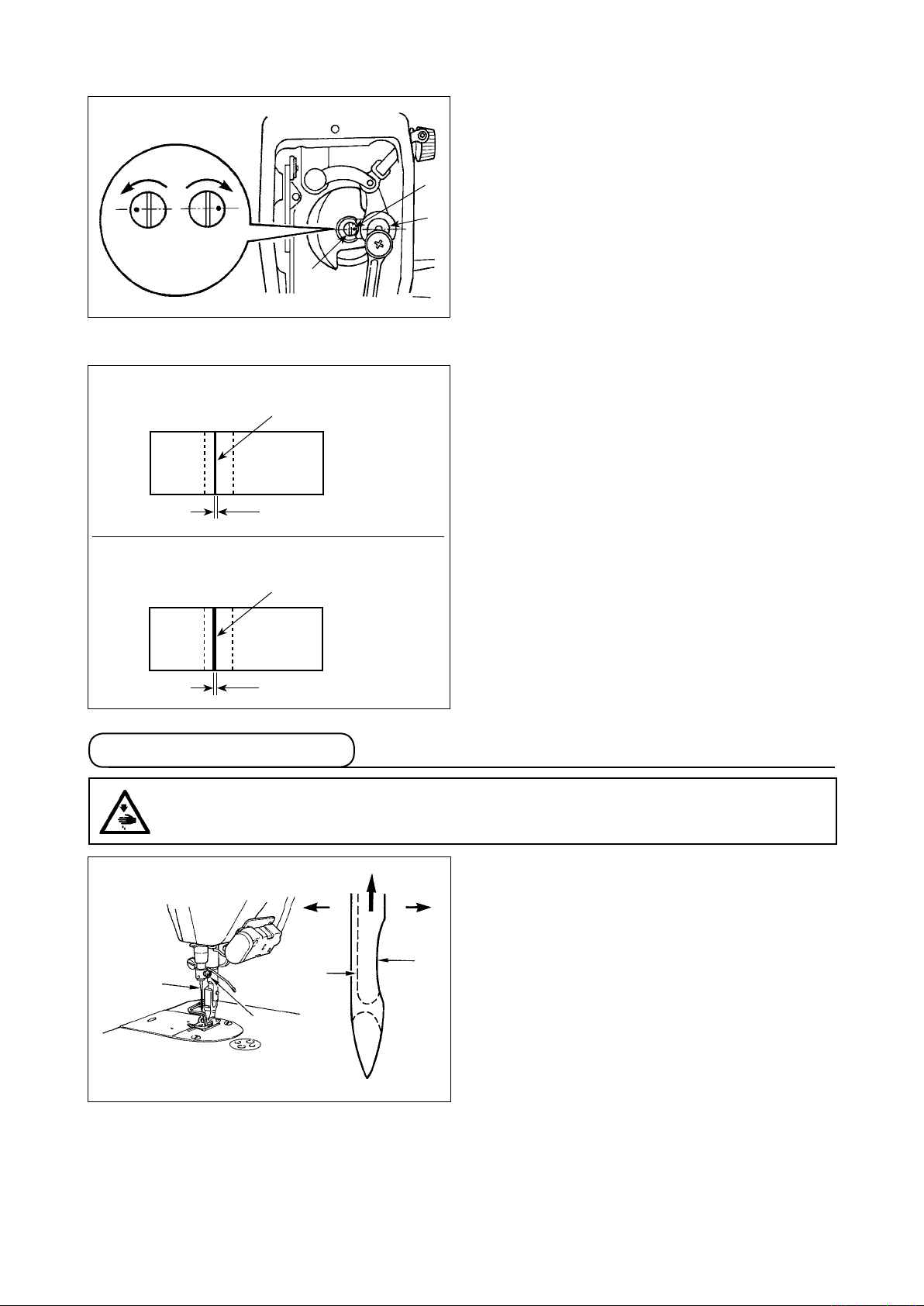
(5) Adjusting the amount of oil supplied to the face plate parts
1) Adjust the amount of oil supplied to the thread
take-up and needle bar crank 2 by turn
just p
in 1.
C
maximum
1
minimum
B
1
A
2) The minimum amount of oil is reached when
is brought close to needle bar
is brought to the position just op-
2
marker dot A
crank 2 by turning the adjust pin in direction B.
3)
The maximum amount of oil is reached when
marker dot A
pos
ite from the needle bar crank by turning the
adjust pin in direction C.
(6) Sample showing the appropriate amount of oil supplied to the face plate parts
ing ad-
Appropriate amount of oil (small)
S
plashes of oil from the thread take-up lever
1 mm
Appropriate amount of oil (large)
S
plashes of oil from the thread take-up lever
2 mm
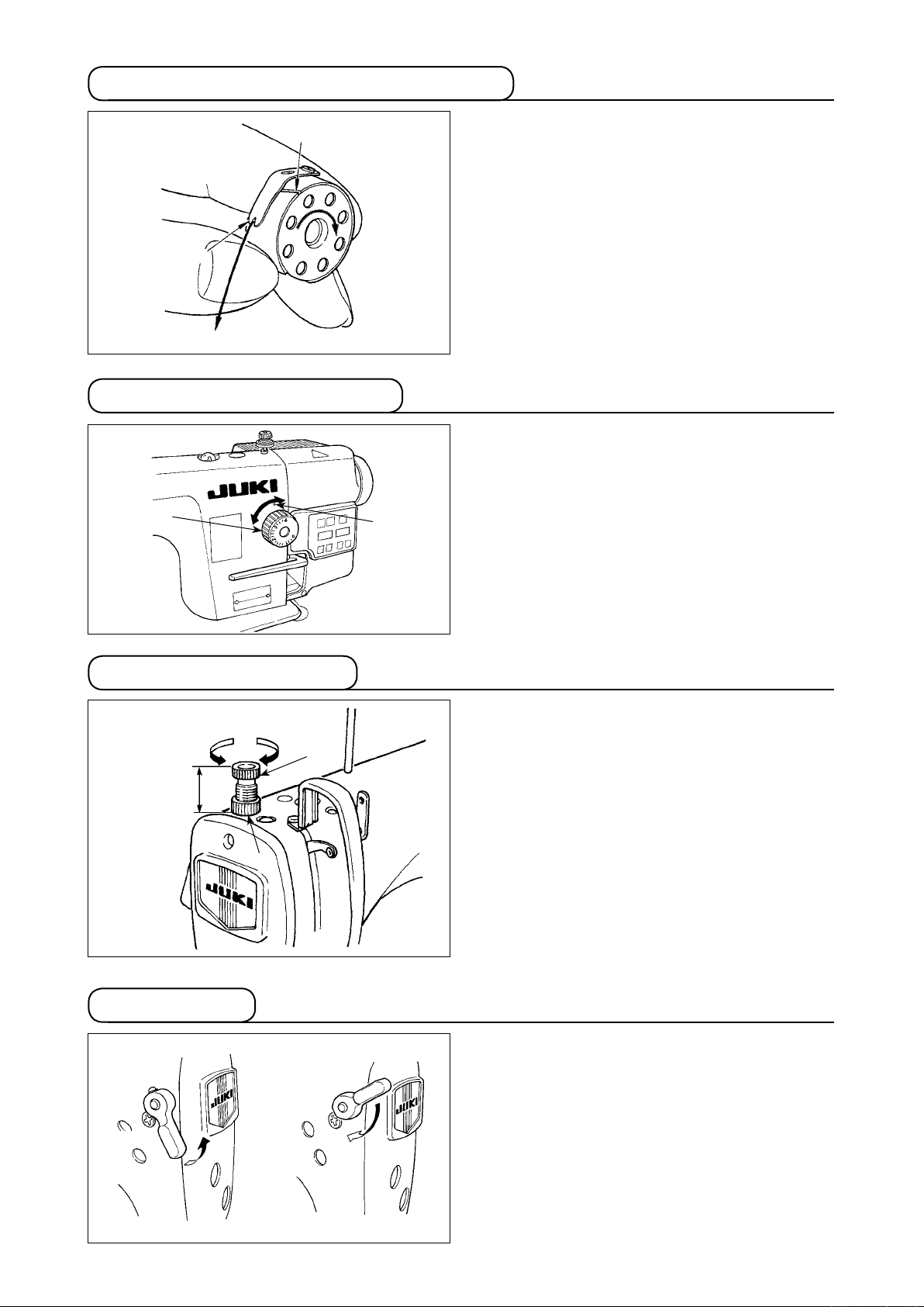
10. Attaching the needle
WARNING :
Be sure to turn the power OFF before the following work in order to prevent personal injury due to
unintentional starting of the sewing machine.
1) The state given in the gure shows the appropr
ate amount of o
il (oil splashes). It is necessary
to nely adjust the amount of oil in accordance
with the sewing processes. However, do not
excessively increase/decrease the amount of oil
in the hook. (If the amount of oil is too small, the
hook will be seized (the hook will be hot). If the
amount of oil is too much, the sewing product
may be stained with oil.)
2) Adjust the amount of oil in the hook so that the
oil amount (oil splashes) should not change
while checking the oil amount three times (on
the three sheets of paper).
i-
Use the specied needle for the machine. Use the
p
roper needle in accordance with the thickness of
D
B
thread used and the kinds of the materials.
1) Turn the handwheel until the needle bar reaches
the highest point of its stroke.
2) Loosen screw 2, and hold needle 1 w
ith its
indented part A facing exactly to the right in
direction B.
3)
Insert the needle fully into the hole in the needle
1
C
A
2
bar in the direction of the arrow until the end of
hole is reached.
4) Securely tighten screw 2.
5) Check that long groove C of the needle
(Caution) When polyester lament thread is used, if the indented part of the needle is tilted toward opera-
tor's side, the loop of thread becomes unstable. As a result, hangnail of thread or thread breakage may
occur. For the thread that such phenomenon is likely to occur, it is effective to attach the needle with its
indented part slightly slanting on the rear side.
is facing exactly to the left in direction D.
– 11 –
Page 15
11. Setting the bobbin into the bobbin case
A
B
C
12. Adjusting the stitch length
1
A
1) Pass the thread through thread slit A, and
pull the thread in direction C. By so do
ing, the
thread will pass under the tension spring and
come out from notch B.
2)
Check that the bobbin rotates in the direction of
the arrow when thread is pulled.
* The dial calibration is in millimeters.
1) Turn stitch length dial 1
in the direction of the
arrow, and align the desired number to marker
dot A on the machine arm.
13. Presser foot pressure
B
29 to 32 mm
A
1
2
14. Hand lifter
1) Loosen nut 2.
As you turn presser spring regu-
lator 1 clockwise (in direction A), the presser
foot pressure will be increased.
2) As you turn the presser spring regulator counter-
clockwise (in direction B), the pressure will be
decreased.
3) After adjustment, tighten nut 2.
The standard value of the pressure regulating thumb
screw is 29 to 32 mm.
1) The presser foot is lifted by moving the lever
upward.
2)
The presser foot is lowered by moving the lever
downward.
– 12 –
Page 16
15. Adjusting the height of the presser bar
WARNING :
Be sure to turn the power OFF before the following work in order to prevent personal injury due to
unintentional starting of the sewing machine.
1
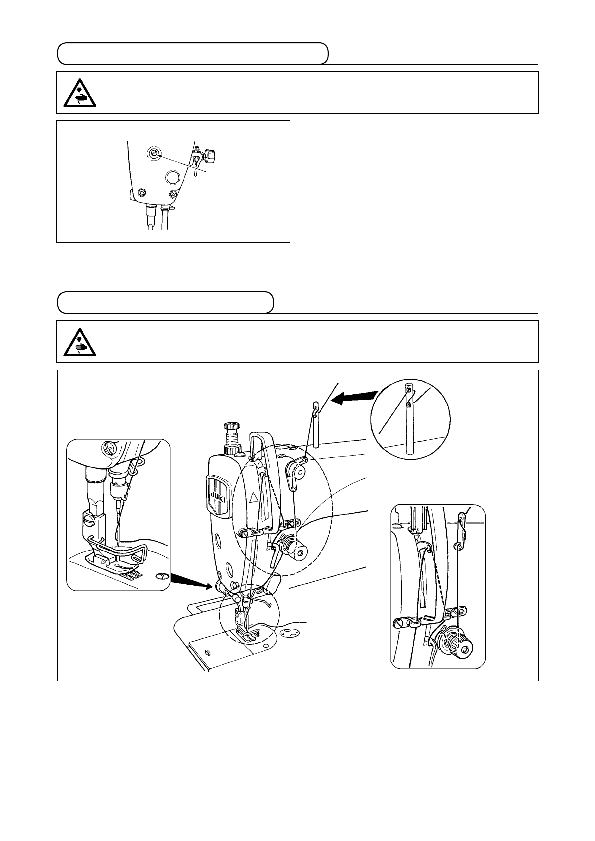
16. Threading the machine head
WARNING :
Be sure to turn the power OFF before the following work in order to prevent personal injury due to
unintentional starting of the sewing machine.
1) Loosen setscrew 1, and adjust the presser bar
height or the angle of the presser foot.
2) After adjustment, securely tighten the setscrew
.
1
– 13 –
Page 17
17. Thread tension
1
B
A
2
3
E
F
(1) Adjusting the needle thread tension
1) The length of thread remaining at the needle
tip after thread trimming is shortened by turning tension regulating nut No. 1 1 clockw
direction A.
2)
It is lengthened by turning the nut counterclock-
wise in direction B.
3) The needle thread tension is increased by turning tension regulating nut No. 2 2 clockw
direction C.
4)
It is decreased by turning the nut counterclock-
wise in direction D.
ise in
ise in
C
D
18. Thread take-up spring
1
2
A
B
3
1
5
4
(2) Adjusting the bobbin thread tension
1) The bobbin thread tension is increased by turning tension regulating screw 3 clockw
ise in
direction E.
2)
It is decreased by turning the screw counter-
clockwise in direction F.
(1) Changing the stroke of thread take-up
spring
1) Loosen setscrew 2.
2) As you turn tension post 3 clockw
t
will be increased.
3) As you turn the knob counterclockwise (in direct
1
ise (in direc-
ion A), the stroke of the thread take-up spr
ion B), the stroke w
ill be decreased.
ing
(2) Changing the pressure of thread take-up
spring
1) Loosen setscrew 2,
2)
Loosen setscrew 4.
3) As you turn tension post 3 clockw
t
4) As you turn the tension post counterclockwise (in
direction B), the pressure will be decreased.
1
and remove tension post 3.
ion A), the pressure w
ise (in direc-
ill be increased.
19. Adjusting the thread take-up stroke
WARNING :
Be sure to turn the power OFF before the following work in order to prevent personal injury due to
unintentional starting of the sewing machine.
BA
1
C
1) When sewing heavy-weight materials, move
thread guide 1 to the left (in direction A) to
increase the length of thread pulled out by the
thread take-up.
2) When sewing light-weight materials, move
thread guide 1 to the right (in direction B) to
decrease the length of thread pulled out by the
thread take-up.
3) Normally, thread guide 1 is positioned in a way
that marker line C is aligned with the center of
the screw.
– 14 –
Page 18
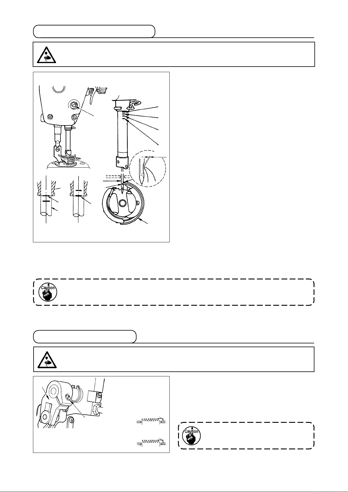
20. Needle-to-hook relationship
WARNING :
Be sure to turn the power OFF before the following work in order to prevent personal injury due to
unintentional starting of the sewing machine.
1
4
3
A
2
5
B
C
D
A
B
0.04 to 0.1 mm
a
(1) Adjust the timing between the needle and
the hook as follows :
1) Turn the handwheel to bright the needle bar
down to the lowest point of its stroke, and
loosen setscrew 1.
(Adjusting the needle bar height)
2)
(For a DB needle)
needle bar 2 with the bottom end of needle bar
lower bushing 3, then tighten setscrew 1.
(For a D
A needle)
needle bar 2 w
lower bushing 3, then tighten setscrew 1.
Align marker line A on
Align marker line C on
ith the bottom end of needle bar
(Adjusting position of the hook a)
3)
(For a DB needle)
setscrews, turn the handwheel and align marker
line B on ascend
tom end of needle bar lower bush
(For a DA needle)
setscrews, turn the handwheel and align marker
line D on ascend
tom end of needle bar lower bush
Loosen the three hook
ing needle bar 2 with the bot-
ing 3.
Loosen the three hook
ing needle bar 2 with the bot-
ing 3.
4) After making the adjustments mentioned in the above steps, align hook blade point 5 with the center
of needle 4. Provide a clearance of 0.04 mm to 0.1 mm (DDL-8700AH-7 : 0.06 to 0.17mm) (reference
value) between the needle and the hook, then securely tighten setscrews in the hook.
If the clearance between the blade point of hook and the needle is smaller than the specied
value, the blade point of hook will be damaged. If the clearance is larger, stitch skipping will
result.
21. Height of the feed dog
WARNING :
Be sure to turn the power OFF before the following work in order to prevent personal injury due to
unintentional starting of the sewing machine.
1
2
0.75 to 0.85 mm
DDL-8700AS-7
1.15 to 1.25 mm
DDL-8700
AH-7
To adjust the height of the feed dog :
Loosen screw 2 of crank 1.
1
Move the feed bar up or down to make adjust-
2
ment.
Securely t
3
If the clamping pressure is insufcient,
ighten screw 2.
th e motion of the forked po rtion becomes heavy.
– 15 –
Page 19

22. Tilt of the feed dog
WARNING :
Be sure to turn the power OFF before the following work in order to prevent personal injury due to
unintentional starting of the sewing machine.
B
A
Front up
a
Front down
c
1
b
d
Standard
T
hroat plate
1) The standard tilt (horizontal) of the feed dog
a
is obtained when marker dot A on the feed
bar shaft is aligned with marker dot B on feed
b
d
rocker 1.
2) To tilt the feed dog with its front up in order to
c
prevent puckering, loosen the setscrew, and
turn the feed bar shaft 90˚ in the direction of the
arrow, using a screwdriver.
3) To tilt the feed dog with its front down in order
to prevent uneven material feed, turn the feed
bar shaft 90˚ in the opposite direction from the
arrow.
Whenever the feed dog tilt is adjusted,
the feed dog height will be changed. So,
it is necessary to check the height after
tilt adjustment.
23. Adjusting the feed timing
WARNING :
Be sure to turn the power OFF before the following work in order to prevent personal injury due to
unintentional starting of the sewing machine.
Standard feed timing
1
2
Advanced feed timing
3
Delayed feed timing
1) Loosen screws 2 and 3 in feed eccentric cam
, move the feed eccentric cam in the direction
1
of the arrow or opposite direction of the arrow,
and rmly tighten the screws.
2)
For the standard adjustment, adjust so that the
top surface of feed dog and the top end of needle
eyelet are ush with the top surface of throat plate
when the feed dog descends below the throat
plate.
3) To advance the feed timing in order to prevent
uneven material feed, move the feed eccentric
cam in the direction of the arrow.
4) To delay the feed timing in order to increase
stitch tightness, move the feed eccentric cam in
the opposite direction from the arrow.
Be careful not to move the feed eccen-
tric cam too far, or else needle breakage
may result.
– 16 –
Page 20

24. Cunter knife
WARNING :
Be sure to turn the power OFF before the following work in order to prevent personal injury due to
unintentional starting of the sewing machine.
a
C
Moving knife
a
Standard : 4.0mm (DDL-8700AH-7: 4.5mm)
c
1
b
c
B
Center of needle
b
A
1
If the knife does not cut thread sharply, immediately
re-sharpen counter knife 1
and re-
install it properly.
as illustrated in Fig. C
1) If the mounting position of the counter knife is
moved in direction A from the standard mount-
ing position, the thread length after thread trim-
ming will be increased accordingly.
2) If the mounting position is moved in direction B,
the thread length will be decreased accordingly.
When sharpening again the knife blade,
extra special care must be taken on the
handling of the knife.
25. Pedal pressure and pedal stroke
WARNING :
Be sure to turn the power OFF before the following work in order to prevent personal injury due to
unintentional starting of the sewing machine.
2
1
3
(1) Adjusting the pressure required to de-
press the front part of the pedal
When the pedal pressure spring 1
the lower side, the pedal pressure will decrease,
and when hooked to the upper side, the pedal
pressure will increase.
is hooked to
(2) Adjusting the pressure required to de-
press the back part of the pedal
The pressure increases as you turn reverse de-
pressing regulator screw 2
in, and decreases as
you turn the screw out.
(3) Adjusting the pedal stroke
The pedal stroke decreases when you insert con-
necting rod 3
into the left hole.
– 17 –
Page 21

26. Adjustment of the pedal
WARNING :
Be sure to turn the power OFF before the following work in order to prevent personal injury due to
unintentional starting of the sewing machine.
1
2
5
4
(1) Installing the connecting rod
1) Move pedal 3 to the r
by the arrows so that motor control lever 1 and
connect
(2) Adjusting the pedal angle
ing rod 2 are stra
1) The pedal tilt can be freely adjusted by changing
the length of the connecting rod.
2) Loosen adjust screw 4, and adjust the length of
connecting rod 2.
ight or left as illustrated
ightened.
3
– 18 –
Page 22

#
. FOR THE OPERATOR
1. Operating procedure of the sewing machine
itch to turn ON
3
3
4
5
1
1) Press ON button 1 of the power sw
the power.
(
Caution) If the backlight of the operation panel
does not light up after the power switch
turned ON, immediately turn the power
is
OFF and check the voltage. In addition,
in such a case as this, re-turn ON the
power swit ch when 2 to 3 minutes or
have passed after turning OFF the
more
power switch.
When the needle bar is not in UP position, it auto-
2)
mat
ically turns to the UP position.
(Caution) When turning ON the power for the rst
time, there is the case where the timing is slightly retarded to perform the
initialization
power, the needle bar moves. Do not put
your hands or things under the needle.
3)
The pedal is operated in the following four steps:
a. The machine runs at low sewing speed when you
lightly depress the front part of the pedal.
b. The machine runs at high sewing speed when you
further depress the front part of the pedal. 3
(If the automat
preset, the machine runs at high speed after it com-
pletes reverse feed stitching.)
c. The machine stops (with its needle up or down)
when you reset the pedal to its original position.
d. The machine trims threads when you fully depress
the back part of the pedal.
work. When turning ON the
ic reverse feed stitching has been
5
* When the auto-lifer (AK device) is used, one more operating switch is provided between the sewing
machine stop switch and thread trimming switch. The presser foot goes up when you lightly depress the
back part of the pedal 4, and
When start
ing sewing from the state that the presser foot has been lifted with the Auto-lifter and you
if you further depress the back part 5, the thread trimmer is actuated.
depress the back part of the pedal, the presser foot only comes down.
• If you reset the pedal to its neutral position during the automatic reverse feed stitching at seam start, the
machine stops after it completes the reverse feed stitching.
• The machine will perform normal thread trimming even if you depress the back part of the pedal immedi-
ately following high or low speed sewing.
• The machine will completely perform thread trimming even if you reset the pedal to its neutral position
immediately after the machine started thread trimming action.
Presser foot operation by
pedal
Pedal depressing depth for
thread trimming
PFL KFL
Enabled D
Deep Shallow
isabled
– 19 –
Page 23

– 20 –
7
4) Reverse feed stitching at the beginning of sewing, reverse feed stitching at the end of sewing
and various sewing patterns can be set on builtin panel 6 of the machine head.
6
5) For some types of the sewing machine heads,
reverse feed is performed by pressing touch-back
switch 7.
2
6) When sewing is completed, press OFF button 2 of
the power switch to turn OFF the power switch after
conrming that the sewing machine has stopped.
Caution) In the case the machine is not used for
(
a long time, remove the power plug from
the plug receptacle.
Page 24

2. Built-in panel of the machine head
1
E
7
B
A
3
1
DC
2
4 5 6
switch : Used for changing over effective/ineffective of the reverse feed stitching pattern.
2
3
switch : Used for changing over effective/ineffective of the overlapped stitching pattern.
switch : Used for conrming the contents of setting and for changing over effective/ineffective of
the reverse feed stitching at sewing start.
4
switch : Used for selecting the process (A, B, C, D) the number of stitches for which is to be
changed.
* The selected process ashes on and off.
switch : Used for changing the content of the selected display (ashing section) and for changing
5
over effective/ineffective of the reverse stitch at sewing end.
switch : Used for changing the content of the selected display (ashing section).
6
7
switch : It is used to call the production support function and to call the one-touch setting (it
should be held pressed for one second).
icators A and B : Various pieces of information are displayed.
Ind
LED C : Lights up when the reverse feed stitching pattern is effective.
LED D : Lights up when the overlapped stitching pattern is effective.
LED E : Lights up when the production support function is displayed.
– 21 –
Page 25

– 22 –
3. Operating procedure of the sewing pattern
(Caution) Refer to the Instruction Manual for each operation panel for how to operate sewing patterns us-
ing other operation panel than the built-in panel of the machine head.
(1) Reverse feed stitching pattern
Reverse feed stitching at sewing start and reverse feed stitching at sewing end can be separately pro-
grammed.
C
1 2
[Setting procedure of the reverse feed stitching]
) Effective/ineffective of the reverse feed stitching
1
A
B
pattern can be changed over by pressing
switch 1.
When the reverse feed st
dered effective, LED C l
itching pattern is ren-
ights up, the number of
stitches of the reverse feed stitching at sew-
i
ng start is displayed on A, and the number of
stitches of the reverse feed stitching at sewing
end is displayed on indicator B.
Select a process (A, B, C or D) the number of
stitches for which is to be changed by using
543
6
switch 4.
The number which is ashing on and of
f repre-
sents the process which is being set.
Change the number of stitches for the selected
process by using
.
6
Press
switch 3 to conrm the
switch 5 and switch
change you
have made. (The number of stitches that can be
set is 0 to 15.)
(Caution) The sewing machine cannot perform sew-
ing when the display of the number of stitches
for a process is ashing on and off.
Without reverse
stitching
everse
R
stitching
Double reverse
stitching
53
play is not ashing on and off, every press on
switch 3 changes over the reverse feed
stitching mode from the "reverse feed stitching
at sewing start," "double reverse feed stitching
at sewing start" and "no reverse feed stitching at
sewing start."
2) When the number of reverse feed stitches dis-
In addition, every time
switch 5
is pressed,
the reverse feed stitching feature changes over
from the reverse feed stitching at sewing end to
the double reverse stitch at sewing end, then to
no reverse feed stitching at sewing end, in turn.
Page 26

(2) Overlapped stitching pattern
Overlapped stitching pattern can be programmed.
A
C
D
C
B
D
2
A
B
A : Number of stitches of normal stitching setting
0 to 15 stitches
B : Number of stitches of reverse stitching setting
0 to 15 stitches
C : Number of stitches of normal stitching setting
0 to 15 stitches
D : Number of times of repetition
0 to 9 times
(Caution) When process D is set to 5 times, the sewing is repeat
ed as A / B /
C / B / C.
[Setting procedure of the overlapped stitching]
1
) Effective/ineffective of the overlapped stitching
pattern can be changed over by pressing
B
switch 2.
When the overlapped st
dered effective, LED D l
itching pattern is ren-
ights up.
-
2) Select a process (A, B, C or D) the number of
stitches for which is to be changed by using
switch 4.
The number which is ashing on and of
f repre-
sents the process which is being set.
543
3) Change the number of stitches for the selected process by using
4) Press
switch 3 to conrm the change you have made.
(The sewing machine does not run unless the setting has been conrmed by pressing
(Caution) The overlapped stitching pattern is carried out under automatic operation mode. Once the pedal
is depressed, the sewing machine will automatically perform sewing of the number of overlapped
stitches.
6
switch 5 and switch 6.
switch 3.)
– 23 –
Page 27

– 24 –
4. One-touch setting
A part of function setting items can be easily changed in the normal sewing state.
(Caution) For the setting of functions other than those covered in this part, refer to "#-6. Setting of func-
tions" p. 28.
Thread trimming function (
1
: Thread trimming operation is not performed (solenoid output prohibition: Thread trimmer, wiper)
: Thread trimming operation is effective.
7
543
6
)
[One-touch setting procedure]
1) Keep
switch 7 held pressed for one second
to place the panel in the function setting mode.
2) Change over the item to be set by using
switch 3 or switch 4. Then, the set value
can be changed by using switch 5 and
switch 6.
3) To return to the normal sewing state, press
switch 7.
(Caution) The setting is conrmed by pressing
switch 7. On
edge sensor, thread trimming by the material
edge sensor and the number of stitches of the
material edge sensor are not displayed in the
default setting at the time of delivery.
e-shot automatic sewing, material
Wiper function (
2
One-shot automatic stitching function (
3
(Caution) This function is rendered effective when the material end sensor function is set. It is not pos-
sible to prohibit the one-shot operation during overlapped sewing operation. The number of revolution
is the value which is set for setting No. 38.
Setting of the max. speed of stitch (
4
: Wiper does not operate after thread trimming.
:
One-shot automatic stitching function is ineffective.
)
: Wiper operates after thread trimming
)
:
One-shot automatic stitching is effective.
)
The highest speed of stitch of the machine head is set. The upper limit of the set value differs with the
type of machine head to which the SC is connected.
Setting range : 150 - Max. value [sti/min]
Material end sensor function (
5
: Material end sensor function is ineffective.
: Once the material end is detected, the sewing machine stops running after having sewn the
number of stitches set with
* This function is rendered effective when the material edge sensor is set with function setting No. 12.
Thread trimming function by material end sensor (
6
: Automatic thread trimming function after the detection of material end is ineffective.
: Once the material end is detected, the sewing machine performs thread trimming after having
sewn the number of stitches set with
* This function is rendered effective when the material edge sensor is set with function setting No. 12.
)
7
(
7
).
(
)
).
Number of stitches for material end sensor (
7
The number of stitches to be sewn from the detection of material end to the stop of the sewing machine
)
Number of stitches that can be set: 0 to 19 (stitches)
(Caution) This function is rendered effective when the material end sensor function is set.
stitches specied is inadequate, the sewing machine can fail to stop within the preset number of stitches
depending on the number of revolutions of the sewing machine.
Adjustment of quantity of light of LED light (
8
The quant
ity of light of the LED light is adjusted
)
If the number of
Setting range : 0 to 100
Page 28

5. Production support function
The production support function consists of three different functions (six different modes) such as the produc-
tion volume management function, operation measuring function and bobbin counter function. Each of them
has its own production support effect. Select the appropriate function (mode) as required.
Production volume management function
■
arget No. of pcs. display mode [F100]
T
Target/actual No. of pcs difference display mode [F200]
The target number of pieces, actual number of pieces and the difference between the target and actual
number of pieces along with the operation time are displayed to notify the operators of a delay and ad-
vance
in real time. Sewing machine operators are allowed to engage sewing while constantly checking
his/her work pace. This helps raise target awareness, thereby increasing productivity. In addition, a delay
in work can be found at an early stage to enable early detection of problems and early implementation of
corrective measures.
Operation measuring function
■
Sewing machine availability rate display mode [F300]
Pitch time display mode [F400]
Average number of revolutions display mode [F500]
Sewing machine availability status is automatically measured and displayed on the control panel. The
data obtained can be used as basic data to perform process analyses, line arrangement and equipment
efciency checkup.
Bobbin counter function
■
Bobb
In order to change bobbins before the current bobbin runs out of thread, the time for replacing the bob-
in counter display mode
bin is notied.
[
To use the production support mode]
721
543
(Caution) Modes F100 to F500 have been factory-
set in the OFF state at the time of delivery.
The mode state is changed over to ON/OFF ac-
cording to the setting of the bobbin thread coun-
ter function (function setting No. 6).
6
Keep
switch 7 held pressed (one second) in
the normal sewing state to call the one-touch setting
screen.
Then, press
switch 1 or switch 2 to set
each production support mode in ON/OFF state to
call the one-touch setting screen.
Press
switch 3 or switch 4 to select the
mode to be set in the ON/OFF state.
ON/OFF of the display can be changed over by
press
ing
switch 5 or switch 6.
To return to the normal sewing state, press
switch 7.
– 25 –
Page 29

– 26 –
Sewing can be performed with the production support data displayed on the control panel.
[Basic operation of the production support modes]
E
7
When
1)
switch 7 is pressed in the normal
sewing state, LED E lights up to enter the pro-
duction support mode.
2)
Production support function can be changed
over by pressing
switch 3 or switch 4.
A
B
3) Data attached marked with (*1) in Table 1 "In-
" can be changed by means of
A
switch 6.
4) When you keep
dicator
switch 5 and
543
6
switch 6 held pressed for two seconds, indicator B and LED E ash on and
off. While they are ashing on and off, data marked with (*2) in Table 1 "Display under modes" can be
changed by pressing
When you press
switch 5 and switch 6.
switch 7, the value marked with (*2) is conrmed and indicator B and LED E stop
ashing on and off.
5)
The value with a sharp mark (*3) in Table 1 "Display of modes" can be changed only immediately after
resetting by using
switch 5 and switch 6.
6) Refer to the table "Mode resetting operation," for the resetting procedure of data.
7) To return to the normal sewing state, press
switch 7.
Data to be displayed under the respective modes are as described in the table below.
Table 1: Display of modes
Mode name Indicator
Target No . of pcs. display
mode (F100)
Target/actual No. of pcs. difference display mode [F200]
Sewing machine availability
rate display mode (F300)
Pit c h t i me d isp l ay m ode
(F400)
Average number of revolutions display mode (F500)
Bobbin co u n t e r display
mode
A
Actual number of pieces
: piece)
Difference between target
number of pieces and actual
number of pieces (d : piece)
(*1)
oP-r Sewing machine availability
Pi-T Pitch time in the previous
ASPd Average number of revolu-
bbn Bobbin counter value (*3) -
(*1)
(Unit
Target number of pieces
: piece)
Target pitch time
(Unit : 100 msec) (*2)
rate in the previous sewing
(Unit : %)
sewing (Unit : 1sec)
tions in the previous sewing
(Unit : sti/min)
Indicator
(*2)
B
Ind ica tor B (when
switch 5 is pressed)
(Unit
-
-
Display of average availability rate of sewing
machine (Unit : %)
Display of average pitch
time (Unit : 100 msec)
Display of average number
of revolutions
(Unit : sti/min)
Page 30

Table 2: Mode resetting operation
Mode name
arget No. of pcs. display mode
T
(F100)
arget/actual No. of pcs. difference
T
display mode (F200)
ewing machine availability rate
S
display mode (F300)
Pitch time display mode (F400) Resets average pitch time Resets average availability rate of sewing
Average number o f revolutions
display mode (F500)
Bobbin counter display mode Resets the bobbin counter value
Switch 5 (held pressed for 2
seconds)
Resets the actual number of pieces
Resets the difference between target
number of pieces and actual number
of pieces
Resets the actual number of pieces
Resets the difference between target
number of pieces and actual number
of pieces
Resets average availability rate of
sewing machine
Resets average number of revolu-
t
ions of sewing machine.
(Note that only the bobbin counter is
Switch 5 (held pressed for 4 sec-
onds)
-
-
Resets average availability rate of sewing
machine.
Resets average pitch time.
Resets average number of revolutions of
sewing machine.
machine.
Resets average pitch time.
Resets average number of revolutions of
sewing machine.
Resets average availability rate of sewing
machine.
Resets average pitch time.
Resets average number of revolutions of
sewing machine.
-
immediately reset by pressing
switch 5.)
[Detailed setting of production volume management function (F101, F102)]
721
When
switch 7 is held pressed (for three sec-
onds) under the target No. of pcs. display mode
(F100) or the target/actual No. of pcs. difference
display mode (F200), the detailed setting of the pro-
duct
ion volume management function can be carried
out.
The setting state of the number of times of thread
trimming (F101) and that of the target achievement
buzzer (F102) can be changed over by pressing
switch 3 or
switch 4.
The number of times of thread trimming for sewing
543
6
one piece of garment can be set by pressing
switch 5 or
switch 6
in the setting state of the number of times of thread trimming (F101).
It is possible to set whether the buzzer sounds or not when the actual number of pieces has reached the tar-
get
volume by pressing
switch 5 or switch 6 i
n the setting state of the target achievement buzzer
(F102).
– 27 –
Page 31

– 28 –
6. Setting of functions
Functions can be selected and specied.
(Caution) Refer to the Instruction Manual for each operation panel for how to operate sewing patterns us-
ing other operation panel than the built-in panel of the machine head.
1) Turn ON the power with switch 7 held
7
pressed.
(The
item which has been changed during the
previous work is displayed.)
* If the screen display does not change, re-carry
out operation described in step 1).
(Caution)
Be sure to re-turn ON the power switch
when one or more seconds have passed after
t
urning it OFF. If the power switch is re-turned
ON immediately after turning it OFF, the sewing
machine may fail to operate normally. In such a
case,
be sure to turn ON the power switch again
properly.
2) To move the setting No. forward, press
switch 4.
press
(Caution) If the setting No. is moved forward (or
backward), the previous (or subsequent) content
of the setting is conrmed. Be careful when the
content of a setting is changed (when the
switch is touched).
To move the setting No. backward,
switch 3.
/
Example) Changing the maximum number of revolu-
tions (setting No. 96)
Press
543
6
ting No. "96."
switch 3 or switch 4 to call set-
The current set value is displayed on indicator B.
Press
switch 5 to change the sett
ing to
"2500."
The content of setting of the setting No. returns
*
to the initial value by pressing
switch 5 and
switch 6 s
3)
After completion of the changing procedure, press
imultaneously.
switch 3 or switch 4 to conrm the updat-
ed value.
(Caution) If the power is turned OFF before carry-
ing out this procedure, the changed content is
543
setting No. When
No. After completion of the operation, the machine is returned to the normal sewing state by turning
OFF the power and re-turning it ON.
switch 4 is pressed, the display on the panel changes to the subsequent setting
6
not updated. When
display on the panel changes to the previous
switch 3 is pressed, the
Page 32

7. Function setting list
No.
1 Soft start
2 Mater
3
4 Number of
5 F
6 Bobb
7 Unit of bobbin
*
8 Number of
*
9 Thread
10 Setting of
11 Operat
12 Optinal switch
13 Function of
*
14 Sewing counter Counting function of sewing (number of completion of process)
15 Thread wiping
Item Description
function
ial end
sensor function
Thread trimming
function by
material end
sensor
itches for
st
material end
sensor
licker reducing
function
in thread
counting
function
thread counting
down
rotation of
reverse feed
stitching
trimming
prohibiting
function
needle bar stop
pos
ition when
the sewing
machine stops.
ion
conrmation
sound for
operation panel
function
selection
prohibiting start
of the sewing
machine by
bobbin thread
counter
function after
thread trimming
The number of stitches to be sewn at a low speed when the softstart function is used at the start of sewing.
0 : The function is not selected.
1 to 9 : The number of stitches to be sewn under the soft-
start mode.
Material end sensor function.
0 : Material end detection function is not operative.
1 : After detecting material end, the specified number of
stitches (No. 4) will be sewn, and the sewing machine will
stop.
Thread trimming function by material end sensor.
0 : Automatic thread trimming function after detection of ma-
terial end is not operative.
1 : After detecting material end, the specified number of
stitches (No. 4) will be sewn, and the sewing machine will
stop and perform automatic thread trimming.
Number of stitches for material end sensor.
Number of stitches from detection of material end to stop of the
sewing machine.
Flicker reducing function
0 : Flicker reducing function is not operative.
1 : Flicker reducing function is effective
Bobbin thread counting function
0 : Bobbin thread counting function is not operative.
1 : Bobbin thread counting function is operative.
Unit of bobbin thread counting down
0 : 1 Count/10 stitches
1 : 1 Count/15 stitches
2 : 1 Count/20 stitches
3 : 1 Count/thread trimming
Sewing speed of reverse feed stitching
Thread trimming prohibiting function.
0 : Thread trimming is effective.
1 : Thread trimming is prohibited.
(Output of solenoid is prohibited. : Thread trimmer and wiper)
Position of needle bar is specified when the sewing machine
stops.
0: The needle bar stops at its lower position.
1: The needle bar stops at its upper position.
Operation conrmation sound for operation panel
0 : Operation conrmation sound is not generated
1 : Operation conrmation sound is generated.
Switching of function of optional switch.
Function of prohibiting start of the sewing machine by bobbin thread counting
0 : When counting is out (-1 or less) Function of prohibiting
start of the sewing machine is not operative.
1 : When counting is out (-1 or less) Function of prohibiting
start of the sewing machine after thread trimming is operative.
2 : When counting is out (-1 or less), the sewing machine
stops once. Function of prohibiting start of the sewing
machine after thread trimming is operative.
0 : Sewing counter function is not operative.
1 : Sewing counter function is operative. (Every time thread
trimming is performed)
2 : With the sewing counting switch input function
Thread wiping operation after thread trimming is specied.
Thread wiping is not carried out after thread trimming
0 :
1 : Thread wiping is carried out after thread trimming
Setting range
0 to 9
(Stitches)
0/1
0/1
0 to 19
(Stitches)
0/1
0/1
0 to 3
150 to 3,000
(sti/min)
0/1
0/1
1
0/
0 to 2
0 to 2
0/1
Indication of function setting
1
2
3
4
5
6
7
8 1 9 0 0
9
1 0
1 1
1 2 o P T _
1 3
1 4
1 5
0
0
0
5
0
1
0
0
0
1
0
1
1
Ref. page
33
33
33
33
33
33
33
33
33
34
37
21 Function of
automatic
presser foot
lifting at pedal's
neutral position
Function of lifting presser foot when the pedal is in neutral position.
0 : Function of neutral automatic presser lifting is not opera-
tive.
1 : Selection of function of neutral presser lifting.
0/1
2 1
0
37
* Do not change the set values with asterisk (*) mark as they are functions for maintenance. If the standard set value set at the
time of delivery is changed, it is in danger of causing the machine to be broken or the performance to be deteriorated.
If it is necessary to change the set value, please purchase the Engineer’s Manual and follow the instructions.
– 29 –
Page 33

– 30 –
No.
22 Needle up/down
25 T
29 Setting of one-
30 Funct
31
32 Ef
33 T
35 Number of
*
36 Number of
*
37 Number of
38 One-shot speed One-shot speed (The max. value depends on the number of ro-
39 Pedal stroke
*
40 Low speed
*
41 Starting position
*
42 Starting position
*
43
*
44
*
45
*
47
48
*
49
Item Description
correction
switch
changeover
function
hread trimming
operation after
turning the
handwheel by
han
touch type
reverse feed
solenoid pull-in
time
ion of
reverse feed
stitching on the
way
Number of
stitches of reverse
feed stitching on
the way
fective
condition of
reverse feed
stitching on the
way when the
sewing machine
is stopping.
hread trimming
function by
reverse feed
stitching on the
way
rotation at a low
speed
rotation of
thread trimming
rotation of softstart
at the start of
rotation
section of pedal
of lifting presser
foot by pedal
of lowering
presser foot
Pedal stroke 2 for
starting thread
trimming
Pedal stroke
for reaching the
maximum number
of rotation
Compensation of
neutral point of
the pedal
Auto-lifter
selecting function
Pedal stroke 1 for
starting thread
trimming
Lowering time of
presser foot
Function of the needle up/down correction switch is changed
over.
0 : Needle up/down compensation
1 : One stitch compensation
Thread trimming operation after moving the needle away from
its upper or lower position by turning the handwheel by hand is
specied.
0 : Thread trimming operation is carried out after turning the
handwheel by hand
1 : Thread trimming operation is not carried out after turning
the handwheel by hand
This function sets the suction time of initial motion of back-tack
solenoid.
50 ms to 500 ms
Function of reverse feed stitching on the way
0 : Normal one-touch type reverse feed stitching function
1 : Function of reverse feed stitching on the way is operative.
Number of stitches of reverse feed stitching on the way.
Effective condition of reverse feed stitching on the way
0 : Function is not operative when the sewing machine stops.
1 : Function is operative when the sewing machine stops.
Thread trimming function by reverse feed stitching on the way
0 : Automatic thread trimming function after completion of
reverse feed stitching on the way is not operative.
1 : Automatic thread trimming after completion of reverse
feed stitching on the way is performed.
Lowest speed by pedal
(The MAX value differs by machine head.)
Thread trimming speed
(The MAX value differs by machine head.)
Sewing speed at the start of sewing (soft-start)
(The MAX value differs by machine head.)
ion of the sewing machine head.)
tat
Position where the sewing machine starts rotating from pedal
neutral position (Pedal stroke)
Position where the sewing machine starts accelerating from
pedal neutral position (Pedal stroke)
Position where the cloth presser starts lifting from pedal neutral
position (Pedal stroke)
Starting position of lowering presser foot
Stroke from the neutral position
Position 2 where the thread trimming starts from pedal neutral
position (When the function of lifting presser foot by pedal is provided.) (Pedal stroke)
(Effective only when Item No. 50 is set at 1.)
Position where the sewing machine reaches its highest sewing
speed from pedal neutral position (Pedal stroke) 10 to 150
Compensation value of the pedal sensor
Limitation time of waiting for lifting solenoid type auto-lifter device
Position where thread trimming starts from pedal neutral position
(Standard pedal) (Pedal stroke)
(Effective only when Item No. 50 is set at 0.)
Sets the time required until the lowering of the presser foot is
completed after a depress on the pedal
Setting range
0/1
0/1
50 to 500
(ms)
0/1
0 to 19
(Stitches)
0/1
0/1
150 to MAX
(sti/min)
100 to MAX
(sti/min)
100 to MAX
(sti/min)
150 to MAX
(sti/min)
10 to 50
(0.1 mm)
10 to 100
(0.1 mm)
– 60 to –10
(0.1mm)
8 to 50
(0.
1 mm)
– 60 to –10
(0.1 mm)
(0.1 mm)
–15 to 15
10 to 600
(second)
– 60
10
to –
(0.1 mm)
0
to 500
10 ms)
(
Indication of function setting
2 2
2 5
2 9
3 0
3 1
3 2
3 3
3 5
3 6
3 7
2 5 0
2 0 0
3 0 0
8 0 0
3 8 2 5 0 0
3 9
4 0
4 1
4 2
4 3
4 4
4 5
4 7
4 8
4 9
3 0
6 0
– 2 1
1 0
– 5 1
1 5 0
6 0
– 3 5
1 4 0
0
1
0
4
0
0
0
Ref. page
37
37
38
38
38
38
33
38
39
41
* Do not change the set values with asterisk (*) mark as they are functions for maintenance. If the standard set value set at the
time of delivery is changed, it is in danger of causing the machine to be broken or the performance to be deteriorated.
If it is necessary to change the set value, please purchase the Engineer’s Manual and follow the instructions.
Page 34

No.
50
Pedal
specication
51 Compensation of
solenoid-on timing
of reverse feed
stitching at the
start of sewing
52 Compensation of
solenoid-off timing
of reverse feed
stitching at the
start of sewing
53 Compensation
of solenoid-off
timing of reverse
feed stitching at
the end of sewing
Foot lift after
55
thread trimming
Reverse
56
revolut
the needle after
thread trimming
Function
58
of holding
predetermined
upper/lower
pos
ition of the
needle bar
Function of Auto/
59
Manual changeover of reverse
feed st
the start of sewing
Function of stop
60
immediately after
reverse feed
st
itching at the
start of sewing
Change-
64
over speed of
condensat
stitch or EBT (end
back tack)
Function of soft-
70
down of presser
foot
Double reverse
71
feed stitching
function
Sewing
72
machine startup
selecting
function
Retry function
73
One-shot function
76
84
Initial motion
suction time of
*
presser foot lifting
solenoid
Item Description
Type of pedal sensor is selected.
0 : KFL
1 : PFL
Refer to
“#-10. Selection of the pedal specications” p.43.
Compensation of starting the solenoid for reverse feed stitching
when reverse feed stitching at the start of sewing is performed.
Compensation of releasing the solenoid for reverse feed stitching when reverse feed stitching at the start of sewing is performed.
Compensation of releasing the solenoid for reverse feed stitching when reverse feed stitching at the end of sewing is performed.
Function of lifting presser foot at the time of (after) thread trimming
0 : Not provided with the function of automatic lifting of work-
clamp after thread trimming
1 : Provided with the function of lifting presser foot
after thread trimming
ion to lift
itching at
ion
Function of reverse revolution to lift the needle at the time of (after) thread trimming
0 : Not provided with the function of reverse revolution to lift
the needle after thread trimming
1 : Provided with the function of reverse revolution to lift the
needle after thread trimming
Function of holding predetermined upper/lower position of the needle bar
0 : Not provided with the function of holding predetermined
upper/lower position of the needle bar
1 : Provided with the function of holding predetermined upper/
lower position of the needle bar (holding force is weak.)
2 : Provided with the function of holding predetermined upper/
lower position of the needle bar (holding force is medium.)
3 : Provided with the function of holding predetermined upper/
lower position of the needle bar (holding force is strong.)
This function can specify the sewing speed of reverse feed
stitching at the start of sewing.
0 : The speed will depend on the manual operation by pedal, etc.
1 :
The speed will depend on the specied reverse feed stitching speed (No. 8).
Function at the time of completion of reverse feed stitching at
the start of sewing
0 : Not provided with the function of temporary stop of the
sewing machine at the time of completion of reverse feed
stitching at the start of sewing
1 : Provided with the function of temporary stop of the sew
ing machine at the time of completion of reverse feed
stitching at the start of sewing.
Initial speed when starting condensation stitch or EBT
Presser foot is slowly lowered.
0 : Presser foot is rapidly lowered.
1 : Presser foot is slowly lowered.
Effective/ineffective of double reverse feed stitching is changed
over.
Current limit at the startup of sewing machine is specied.
This function is used when needle cannot pierce materials .
(Needle-bar returning force before re-trying: 1 (small) - 10 (large))
One-shot operation up to the material end is specied.
Suction motion time of presser foot lifting solenoid
fective
0 : Inef
1 : Effective
0 : Normal (Current limit is applied during startup)
1 : Rapid (Current limit is not applied during startup)
0 : Re-try function is not provided
1 - 10: Re-try function is provided
0 : One-shot operation is not performed.
1 : One-shot operation is performed.
automatically
Setting range
– 36 to 36
– 36 to 36
– 36 to 36
0 to 3
-
0 to 250
(sti/min)
50 to 500
0/1
(10°)
(10°)
(10°)
0/1
0/1
0/1
0/1
0/1
0/1
0/1
0/1
0/1
(ms)
Indication of function setting
5 0
5 1
5 2
5 3
5 5
5 6
5 8
5 9
6 0
6 4
7 0
7 1
7 2
7 3
7 6
8 4
1 2
1 8
1 6
1 8 0
2 5 0
1
1
0
0
1
0
0
1
0
1
0
Ref. page
43
39
39
39
40
40
40
40
40
41
41
33
41
* Do not change the set values with asterisk (*) mark as they are functions for maintenance. If the standard set value set at the
time of delivery is changed, it is in danger of causing the machine to be broken or the performance to be deteriorated.
If it is necessary to change the set value, please purchase the Engineer’s Manual and follow the instructions.
– 31 –
Page 35

– 32 –
No.
87
Function of pedal
curve selection
Item Description
Pedal curve is selected. (Improving pedal inching operation)
Number of rotations
2
0
1
Pedal stroke
Setting range
0/1/2
Indication of function setting
8 7
0
Ref. page
41
Initial motion up
90
stop function
Function of prohibiting
91
compensation
operation after turning
handwheel by hand
Function of
92
reducing speed
of reverse feed
itching at the
st
start of sewing
Function added to
93
needle up/down
compensat
switch
Continuous +
94
One-shot nonstop
ion
funct
Head select
95
function
Max. number of
96
rotation setting
Number of
100
itches sewn
st
before thread
clamp works at
the beg
sewing
Needle cooler
103
output OFF
delay t
ime
LED light
109
dimmer utility
setting
Main shaft
120
reference angle
compensat
Up position
121
starting angle
compensation
DOWN position
122
starting angle
compensation
Setting of
124
energy-saving
function during
standby
ing
ion
inning of
ion
Automatic UP stop function is set immediately after turning ON the
power.
0 : off
1 : on
It is effective in combination with the machine head provided
with tension release function.
0 : Tension release function is ineffective.
1 : Tension release function is effective.
Function to reduce speed at the time of completion of reverse
feed stitching at the start of sewing.
0 : Speed is not reduced.
1 : Speed is reduced.
Operation of needle up/down compensating switch is changed
after turning ON the power or thread trimming.
0 : Normal (needle up/down compensating stitching only)
1 : One stitch compensating stitching is performed only when
aforementioned changeover is made. (Upper stop
per stop)
The function that does not stop the sewing machine by combining continuous stitching with one-shot stitching using the
program sewing function which is available in the IT operation
panel.
0 : Normal (The sewing machine stops when a step is com-
pleted.)
: The sewing machine does not stop when a step is com-
1
pleted and proceeds to next step.
Machine head to be used is selected.
(When the machine head is changed, each setting item is changed
to the initial value of the machine head.)
Max. number of rotation of the sewing machine head can be set.
(The MAX value differs by machine head.)
Sets the number of stitches to be sewn at the beginning of sew
i
ng before the thread clamp solenoid (CN36-7) starts operating
0: Thread clamp solenoid does not operate.
1-9: The number of stitches to be sewn before the thread clamp
solenoid operates
Delay time from the stop of sewing machine to the output OFF is
specied using the needle cooler output function.
Used to adjust brightness of the LED light
0: Output OFF
Main shaft reference angle is compensated.
Angle to detect UP position starting is compensated.
Angle to detect DOWN position starting is compensated.
ing to reduce the power consumption while the sewing ma-
Sett
chine is in standby state
0: Energy-saving mode is ineffective
1: Energy-saving mode is effective
up-
/
150 to MAX
(sti/min)
-
(st
2000 ms
0 to
–60 to 60
–15 to 15
–15 to 15
0/1
0/1
0/1
0/1
0/1
0-9
itches)
100 to
100%
0/1
9 0
9 1
9 2
9 3
9 4
9 5 8 7 A S
9 6 4 0 0 0
1 0 0
1 0 3
1 0 9
1 2 0
1 2 1
1 2 2
1 2 4
5 0 0
1 0 0
– 1 3
1
42
1
0
41
0
42
0
42
42
0
42
42
5
42
0
42
0
42
* Do not change the set values with asterisk (*) mark as they are functions for maintenance. If the standard set value set at the
time of delivery is changed, it is in danger of causing the machine to be broken or the performance to be deteriorated.
If it is necessary to change the set value, please purchase the Engineer’s Manual and follow the instructions.
Page 36

8. Detailed explanation of selection of functions
Selection of the soft-start function (Function setting No. 1)
1
The needle thread may fail to interlace with the bobbin thread at the start of sewing when the stitching pitch
(stitch length) is small or a thick needle is used. To solve such problem, this function (called “soft-start”) is
used to l
The sewing speed limited by the soft-start function can be changed. (Function setting No. 37)
2
Th
For details, refer to "#-16. C
the mater
3
The function reduces ickering of the hand lamp at the start of sewing.
imit the sewing speed, thereby assuring successful formation of the starting stitches.
0 : The function is not selected.
1 0
1 to 9 : The number of stitches to be sewn under the soft-start mode.
Data sett
3 7 08 0
ing range
100 to MAX sti/min <10 sti/min> (The MAX value differs by machine head.)
Material end sensor function (Function setting No. 2 to 4, 76)
is function is possible when the material end sensor is attached.
onnection of the material and sensor" p. 49
and the Instruction Manual for
ial end sensor.
Flicker reducing function (Function setting No. 5)
0 : Fl
5 0
icker reducing function is ineffective
1 : Flicker reducing function is effective
(Caution) When the icker reducing function is set at the "Flicker reducing function is effective," the
startup speed of the sewing machine decreases.
Bobbin thread counting function (Function setting No. 6)
4
When the control panel is used, the function subtracts from the predetermined value and indicates the used
amount of bobbin thread.
For the details, refer to the instruction manual for the control panel.
0 : Bobbin thread counting function is not operative.
6 1
1 : Bobbin thread counting function is operative.
(Caution) If “0” is set, the LCD indication on the control panel will go out and the bobbin thread count-
ing function will be invalid.
Thread trimming prohibiting function (Function setting No. 9)
5
This function turns OFF thread trimming solenoid output and wiper solenoid output when thread trimming is
actuated.
By this function, separate sewing material can be spliced and sewn without trimming thread.
0 : off Thread trimming is operative. (thread can be trimmed).
1 : on Thread trimming is inoperative. (thread can not be trimmed).
Setting of the needle bar stop position when the sewing machine stops (Function setting No. 10)
6
9 0
The position of the needle bar when the pedal is in its neutral position is specied.
0 : Down
1 0 0
The needle bar stops in the lowest position of its stroke.
1 : Up The needle bar stops in the highest position of its stroke.
(Caution) If the stop position of the needle bar is set to the highest position, the thread trimming action
will be taken after the needle bar comes down once to the lowest position.
Panel operating sound (Function setting No. 11)
7
Whether the panel operation generates sound or not can be selected.
0 : off Operation conrmation sound is not generated
1 1 1
1 : on Operation conrmation sound is generated.
– 33 –
Page 37

– 34 –
Selection of the optional input/output function (Function setting No. 12)
8
2 TPo _
21
7
1
Select function setting No. 12 with the operating pro-
cedure of function setting procedures 1) through 3).
A
B
0i 1 ** *
<? <?
1i 7
0o 1 ** *
0o 3
o
TP
_
nE_ d
_ni _
Tuo _
Select the items of "End", "in" and "ouT" with keys 5
and 6.
543
6
[When "in" is selected]
The i
nput function setting connector indication number is shown on indicat-
i
ng section A.
Spec
ify the function of the pin of the connector corresponding to the indica-
Designate the indication number by means of key 3 or 4.
tion number by means of key 5 or 6.
Function code and abbreviation are displayed alternately on indicator B.
(For the relation between signal input No. and connector pin array, refer to
the separate list.)
[When "ouT" is selected]
The output function setting connector indication number is shown on indicating section A.
Spec
ify the function of the pin of the connector corresponding to the indica-
Designate the indication number by means of key 3 or 4.
tion number by means of key 5 or 6.
Function code and abbreviation are displayed alternately on indicator B.
(Refer to the separate table for the relation between the signal output num-
bers and the connector pin conguration.)
Example) To assign the thread trimming function to the input function setting connector indication number "i01" (CN36-4)
*
1 2 TPo _
1. Select function setting No. 12 with the operating procedure of function
setting procedures 1) through 3).
o
TP
_
0i 1 on P
0i 1 ST W
0i 1
_ni _
[\
Lighting alternately
L 4
L 4
[\
2. Select the item of "in" with keys 5 and 6.
3. Select the port of the indication number "i01" by means of key 4.
4. Select the thread trimming function, "TSW" with keys 5 and 6.
5. Determine the thread trimming function, "TSW" with key 4.
6. Set ACTIVE of the signal with keys 5 and 6.
Set the display to "L" when the signal is "Low" and performing thread
trimming, and set the display to "H" when the signal is "High" and per-
H 4
0i 2 SFS W
o
TP
_
_ni _
forming thread trimming.
7. Determine the aforementioned function with key 4.
8. Finish the optional input with key 4.
o
TP
_
nE_ d
9. Select the item of "End" with keys 5 and 6
t
ing mode.
to return to the function set-
Page 38

Input function list
Function
code
0 noP No funct
1 HS N
2 bHS Back compensat
3 EbT Function of c anceling once re-
4 TSW Thread tr
5 FL Presser foot l
6 oHS One st
7 SEbT Funct
8 PnFL P
9 Ed Mater
10 LinH Function of prohibiting depressing
11 Ti
12 LSSW Low speed command
13 HSSW H
14 USW Needle l
15 bT R
16 SoFT Soft start sw
17
18
1
20
21
22
23 Tii
24 USTP Lsw
Abbrev
ia-
ion
t
eedle up / down compensating
stitching
verse feed stitching at the end of
sewing
stitching at start/end
resser lifting function when pedal
is neutral
front part of pedal
nH Fun ction of pro hibit ing t hread
trimming output
igh speed command input This function works as high speed switch for standing
everse feed stitching switch in-
put
oSSW
bKoS
9
SFSW
MES
AUbT
CUnT
One-shot
input
Backward one-shot speed command sw
Safety sw
Thread
put
A
utomatic reverse feed stitching
cancellation/addition switch
Sewing counter input
n Tsw command prohibition input Thread trimming command is prohibited.
up stop input
Function item
ion (Standard setting)
ing stitching
imming function This function is actuated as the thread trimming switch.
ifting function This function is actuated as the foot lifter switch.
itch compensating stitching Every time the switch is pressed, one stitch stitching op-
ion of cancel of reverse feed
ial edge sensor input
input This function works as low speed switch for standing
ifting function UP stop motion is performed when switch is pressed dur-
itch input The speed of stitch is limited to the predetermined soft-
speed command switch
itch input
itch input Rotation is prohibited.
trimming safety switch in-
command prohibition/needle-
Remarks
Every time the switch is pressed, normal feed stitching
by half stitch is performed. (Same operation as that of up
/ down compensating stitching switch on the panel.)
Reverse feed stitching is performed at low speed while the
switch is held pressing.
By depressing the back part of the pedal after pressing
the switch, operation of reverse feed stitching is can
celed once.
eration is executed.
By operating the optional switch, ineffective/effective can
be alternately changed over.
Every time the switch is pressed, the function whether
automatically lifting the presser foot when the pedal is
neutral or not can be selected.
This function works as the input signal of material edge sensor.
Rotat
ion by pedal is prohibited.
Output of thread trimming is prohibited.
sewing machine.
sewing machine.
ing DOWN stop.
Reverse feed stitching is output as long as the switch is
held pressed.
start speed as long as the switch is held pressed.
This function works as one-shot speed command as long
as the switch is pressed.
Reverse feed stitching is performed in accordance with
the one-shot speed command as long as the switch is
held pressed.
I
t operates as an input signal of the thread trimmer safety
switch.
Every time the switch is pressed, reverse feed stitching
at sewing start or reverse feed stitching at sewing end is
cancelled or added.
Every time the switch is pressed, the sewing counter
value is increased.
Sewing by means of the pedal switch is prohibited.
The sewing machine stops with its needle up during
sewing.
-
– 35 –
Page 39

– 36 –
Input function setting connectors
Connector No. Pin No. Display No. Initial value of function setting
CN36 4 i
CN54 3 i
CN50 1
CN36 5 i
CN50 11 i
CN39
CN57 1 i1
2 i03 SoFT (Soft-start speed limit input)
7 i
11 i
9 i
5 i
01 noP (No function setting)
02 noP (No function setting)
04 bT (Reverse feed stitching switch input)
05 LinH (Input of prohibition of depress on front part of pedal)
06 TSW (Thread trimming switch input)
07 LSSW (Low-speed revolution switch input)
08 HSSW (High-speed revolution switch input)
09 FL (Presser foot lifting switch input)
0 CUnT (Sewing counter input)
i11 noP (No function setting)
i12 noP (No function setting)
i13 noP (No function setting)
Built-in panel
* The built-in panel settings i11 to i17 are only enabled when the external panel is connected to the sewing machine.
Their numbers are not displayed when the external panel is not connected to the sewing machine.
i14 noP (No function setting)
i15 noP (No function setting)
i16 noP (No function setting)
i17 noP (No function setting)
Output function list
Function
code
10 CooL Needle cooler output Output for needle cooler
11 bUZ Buzzer output
12 LSWo Revolut
13 TSWo T
Abbrev
ia-
ion
t
0 noP No funct
1 TrM Thread trimming output Output of thread trimming signal
2 W
3 TL Thread release output Output of thread release s
4 FL Presser l
5 bT Reverse feed st
6 EbT EBT
7 SEbT R
8 AUbT S
9 SSTA Sew
iP Thread wiper output Output of thread wiper signal
everse feed stitching at start/end
cancel monitor output
ewing start/end cancellation/addi-
tion monitor output
sw command monitor output Thread trimming command status is output.
Function item
ion
ifter output Output of presser lifting signal
itching output Output of reverse feed stitching signal
cancel monitor output State of one time cancel of reverse feed stitching at end
ing machine stop state output Sewing machine stop state is output.
ion command output Revolution demanding command state is output.
(Standard setting)
function is output.
State of cancel of reverse feed stitching at start/end is
output.
State of cancel or addition of automatic reverse feed
stitching is output.
It i
s output when the bobbin counter set value has been
exceeded, an error has occurred or the bobbin thread
remaining amount is detected.
Remarks
ignal
Output function setting connector
Connector No. Pin No. Display No. Initial value of function setting
1 bT (Reverse feed stitching output)
rM (Thread trimming output)
o (Revolution request input)
CN50
7 o0
8 o02 T
9 o03 LSW
Page 40

Sewing counting function (Function setting No. 14)
9
The function counts up every time thread trimming is completed and counts the number of completion of the
sewing process.
0 : off Sewing counting function is inoperative.
1
4 1
1 : on Sewing counting function is operative. (Every time thread trimming
is performed)
2 : on External sewing counter switch input.
The counter indication changes as shown below according to the combination of setting No. 6 and setting
No. 14.
Setting No. 6 Setting No. 14 Counter
1 1 Bobb
1 0 Bobb
0 1 Sew
0 0 Counter funct
in counter
in counter
ing counter
ion is ineffective.
Neutral automatic presser lifting function (with A
!0
K device only) (Functionsetting No. 21)
This function can automatically lift the presser foot when the pedal is in the neutral position.
Automatic lifting time of the pedal depends on the automatic lifting time after thread trimming and when the
presser foot is automatically lowered, it is automatically lifted at the second neutral position after it has come
off the neutral position once.
0 : off Function of neutral automatic presser lifting is not operative.
2 1 0
1 : on Selection of function of neutral automatic presser lifting
Needle up/down switch function changeover function (Function setting No. 22)
!1
The
needle up/down switch function can be changed over between the needle up/down compensation and
one stitch compensation.
0 : Needle up / down compensating stitching
2 2 0
1 : One stitch compensating stitching
Setting of the suction time of the back-tack solenoid (Function setting No. 29)
!2
is function can change the suction time of the back-tack solenoid.
Th
It is effective to decrease the value when the heat is high.
(Caution) When the value is excessively decreased, failure of motion or defective pitch will follow.
Be careful when changing the value.
Setting range : 50 to 500 ms <10 / ms>
2 9 52 0
– 37 –
Page 41

– 38 –
Function of reverse feed stitching on the way (Function setting Nos. 30 to 33)
!3
Functions of the limit of number of stitches and thread trimming command can be added to the touch back
switch on the sewing machine head.
Function setting No. 30 Function of reverse feed stitching on the way is selected.
0 : off Normal back-tack function
3 0 0
1 : on Function of reverse feed stitching on the way
Function setting No. 31 Number of stitches performing reverse feed stitching is set.
Setting range
3 1 4
0 to 19 stitches
Function setting No. 32 Effective condition of reverse feed stitching on the way
3 2 0
0 : off Inoperative when the sewing machine stops. (Reverse feed stitch-
ing on the way functions only when the sewing machine is running.)
1 : on Operative when the sewing machine stops.
(Reverse feed stitching on the way functions both when the sew-
ng machine is running and stops.)
i
(Caution) Either condition is operative when the sewing machine is running.
Function setting No. 33
0 : off Without thread trimming
3 3 0
Thread trimming is performed when reverse feed stitching on the way is completed.
1 : on Thread trimming is executed.
Application
1
2
3
4
5
Function setting
No.30 No.32 No.33
0 0 or
1 0 0
1 1 0
1 0 1
1 1 1
1 0 or 1 It works as normal touch-back switch.
Output function
hen operating touch-back switch at the time of depressing front part of the
W
pedal, reverse feed stitching as many as the number of stitches specied by the
function setting No. 31 can be performed.
hen operating touch-back switch at the time of either stop of the sewing machine
W
or depressing front part of the pedal, reverse feed stitching as many as the number
of stitches specied by the function setting No. 31 can be performed.
When operating touch-back switch at the time of depressing front part of the pedal,
automatic thread trimming is performed after reverse feed stitching as many as the
number of stitches specied by the function setting No. 31 has been performed.
When operating touch-back switch at the time of either stop of the sewing ma-
hine or depressing front part of the pedal, automatic thread trimming is per-
c
formed after reverse feed stitching as many as the number of stitches specied
by the funct
ion setting No. 31 has been performed.
Actions under each setting state
Used as the normal reverse feed stitching touch-back switch.
1
Used for reinforcing seam (press sewing) of the pleats. (It works only when the sewing machine is running.)
2
Used for reinforcing seam (press sewing) of the pleats.
3
(It works either when the sewing machine stops or when the sewing machine is running.)
Used as start
4
(Used as the substitute for thread trimming by depressing back part of the pedal. It works only when the sewing
machine is running. It is especially effective when the sewing machine is used as the standing-work machine.)
Used as start
5
(Used as the substitute for thread trimming by depressing back part of the pedal. It works either when the sewing
machine stops or when the sewing machine is running. It is especially effective when the sewing machine is used
as the standing-work machine.)
ing switch for reverse feed stitching at the sewing end.
ing switch for reverse feed stitching at the sewing end.
Number of rotation of one-shot stitching (Function setting No. 38)
!4
Th
is function can set, by the pedal operation of one time, the sewing speed of one-shot stitching when the
sewing machine continues stitching until completing the number of stitches specied or detecting the material
end.
Sett
3 8 052 0
ing range
150 to MAX. sti/min. <50 / sti/min>
(Caution) The max. number of rotation of one-shot stitching is limited by the model of the sewing ma-
chine head.
Page 42

Holding time of lifting presser foot (Function setting No. 47)
!5
Th
is function automatically lowers the presser foot when the time set with the setting No. 47 has passed after
lifting the presser foot.
When the pneumatic type presser foot lifter is selected, the holding time control of lifting presser foot is limit
less regardless of the set value.
Sett
7 6 0
4
ing range
10 to 600 sec <10 / sec>
ompensation of timing of the solenoid for reverse feed stitching (Function setting No. 51 to 53)
C
!6
When the normal and reverse feed stitches are not uniform under the automatic reverse feed stitching action, this
function can change the ON / OFF timing of the solenoid for back tack and compensate the timing.
Compensation of on-timing of solenoid for reverse feed stitching at the start of sewing (Function setting
1
No. 51)
On-timing of solenoid for reverse feed stitching at the start of sewing can be compensated by the unit of angle.
Adjusting range
– 36 to 36 <1 / 10˚>
5 1 1 2
Set value
36
–
8
1
–
0 0
8 180
1
36 360
Compensation angle
360
–
゜ –
180
–
゜ –
゜
゜
゜
Number of stitches of compensation
1
0.5
0
0.5
1
– 360˚
– 180˚
180˚
360˚
* When the point
before 1 stitch is
regarded as 0˚,
compensation is
0˚
possible by 360˚ (1
stitch) in front and in
the rear.
-
Compensation of off-timing of solenoid for reverse feed stitching at the start of sewing (Function setting No. 52)
2
Off-timing of solenoid for reverse feed stitching at the start of sewing can be compensated by the unit of angle.
Adjusting range
– 36 to 36 <1 / 10˚>
Compensation of off-timing of solenoid for reverse feed stitching at the end of sewing (Function setting No. 53)
3
5 2 1 8
Set value
36
–
8
1
–
0 0
8 180
1
36 360
Compensation angle
360
–
゜ –
180
–
゜ –
゜
゜
゜
Number of stitches of compensation
1
0.5
0
0.5
1
– 360˚
– 180˚
0˚
180˚
360˚
Off-timing of solenoid for reverse feed stitching at the start of sewing can be compensated by the unit of angle.
Adjusting range
5 3 1 6
– 36 to 36 <1 / 10˚>
Set value
36
–
8
1
–
0 0
8 180
1
36 360
Compensation angle
360
–
゜ –
180
–
゜ –
゜
゜
゜
Number of stitches of compensation
1
0.5
0
0.5
1
– 360˚
– 180˚
0˚
180˚
360˚
– 39 –
Page 43

– 40 –
Foot lift function after thread trimming (Function setting No. 55)
!7
This function can automatically lift the presser foot after thread trimming. This function is effective only when
it is used in combination with the AK device.
0 : off Function of automatically lifting the presser foot is not provided.
5
5 1
(Presser foot does not automatically go up after thread trimming.)
1 : on Function of automatically lifting the presser foot is provided.
(Presser foot automatically goes up after thread trimming.)
Reverse revolution to lift the needle after thread trimming (Function setting No. 56)
!8
This function is used to make the sewing machine rotate in the reverse direction after thread trimming to lift
the needle bar almost to highest position. Use this function when the needle appears under the presser foot
and it is likely to make scratches on the sewing products of heavy-weight material or the like.
0 : off Function of making the sewing machine rotate in the reverse direc
5 6 0
ion to lift the needle after thread trimming is not provided.
t
1 : on Function of making the sewing machine rotate in the reverse direc-
tion to lift the needle after thread trimming is provided.
(Caution) The needle bar is raised, by rotating the machine in the reverse direction, almost to the high-
est dead point. This may result in slip-off of the needle thread. It is therefore necessary to
adjust the length of thread remaining after thread trimming properly.
-
Function of holding predetermined upper / lower position of the needle bar (Function setting No. 58)
!9
When the needle bar is in the upper position or in the lower position, this function holds the needle bar by applying a brake slightly.
0 : off Not provided with the function of holding predetermined upper/low-
5 8 0
er position of the needle bar
1 : on Provided with the function of holding predetermined upper/lower
position of the needle bar (holding force is weak.)
2 : on Provided with the function of holding predetermined upper/lower
position of the needle bar (holding force is medium.)
3 : on Provided with the function of holding predetermined upper/lower
position of the needle bar (holding force is strong.)
C
hange-over function of AUTO / Pedal for sewing speed of the reverse feed stitching at the start
@0
of sewing (Function setting No. 59)
This function selects whether the reverse feed stitching at the start of sewing is performed without a break at
the speed set by the function setting No. 8 or the stitching is performed at the speed by the pedal operation.
0 : Manual The speed is indicated by the pedal operation.
5 9 1
1 : Auto Automatic stitching at the specied speed
(Caution)
1. The max. sewing speed of the reverse feed stitching at the start of sewing is limited to the speed set
by the function setting No. 8 regardless of the pedal.
2.
When “0” is selected, stitches of reverse feed stitching may not match those of normal feed stitching.
Function of stop immediately after the reverse feed stitching at the start of sewing (Function setting No. 60)
@1
This function temporarily stops the sewing machine even when keeping depressing the front part of the pedal at the
time of completion of process of reverse feed stitching at the start of sewing.
It is used when sewing a short length by reverse feed stitching at the start of sewing.
6 0 0
0 : Not provided with the function of temporary stop of the
sewing machine immediately after the reverse feed
stitching at the start of sewing
1 : Provided with the function of temporary stop of the
Stop the sewing machine
temporarily to change
direction of sewing products.
sewing machine immediately after the reverse feed
stitching at the start of sewing
Page 44

Function of soft-down of presser foot (with AK device only) (Function setting No. 70 and 49)
@2
This function can softly lower the presser foot.
This function can be used when it is necessary to decrease contact noise, cloth defect, or slippage of cloth at
the time of lowering the presser foot.
Note : Change the time of function setting No. 49 together at the time of selecting the function of soft-
down since the sufcient effect cannot be obtained unless the time of function setting No. 49 is
set longer when lowering the presser foot by depressing the pedal.
0 to 500 ms
4 9 41 0
10 ms/Step
0 : Function of soft-down of presser foot is not operative. (Presser foot is
7 0 0
rapidly lowered.)
1 : Selection of function of soft-down of presser foot
Function of reducing speed of reverse feed stitching at the start of sewing (Function setting No. 92)
@3
Function to reduce speed at the time of completion of reverse feed stitching at the start of sewing : Normal
use depending on the pedal condition (Speed is accelerated to the highest without a break.)
This function is used when temporary stop is used properly. (Cuff and cuff attaching)
0 : Speed is not reduced.
9 2 0
1 : Speed is reduced.
Temporary stop
Retry function (Function setting No. 73)
@4
Sew without stopping
without a break.
When the retry function is used, if the sewing material is thick and not pierced with needle, this function
makes the needle pierce in the material with ease.
0 : Re-try funct
7 3 1
ion is not provided
1 - 10 : Re-try function is provided
(Needle-bar returning force before re-trying: 1 (small) - 10 (large))
Presser foot lifting solenoid suction time setting (Function setting No. 84)
@5
Suction time of presser foot lifting solenoid can be changed. When heating is great, it is effective to lessen
the value.
(Caution) When the value is excessively small, malfunction will be caused. So, be careful when chang-
ing the value.
Setting range : 50 to 500ms <10/ms>
8 4 52 0
Function of pedal curve selection (Function setting No. 87)
@6
Th
is function can perform the selection of the curve of number of rotation of the sewing machine against the
depressing amount of the pedal.
Change to this function when you feel that inching operation is hard or that pedal response is slow.
7 0
8
0 : Number of rotation of the sewing
2
machine in terms of the depress-
ng amount of the pedal increases
i
0
linearly.
1 : Reaction to intermediate speed in
terms of the depressing amount of
Number of rotation
the pedal is delayed.
(sti/min)
Pedal stroke (mm)
2 : Reaction to intermediate speed in
terms of the depressing amount of
the pedal is advanced.
– 41 –
1
Page 45

Initial motion
7
@
Effective/ineffective of automatic return to UP stop position immediately after turning ON the power can be set.
0 : Ineffective
1 : Effective
Function added to the needle up / down compensating switch (Function setting No. 93)
@8
One stitch operation can be performed only when the needle up / down compensating switch is pressed at the time of
upper stop immediately after turning ON the power switch or upper stop immediately after thread trimming.
0 : Normal (Only needle up / down compensating stitching operation)
1 : One stitch compensating stitching operation (upper stop / upper stop)
Continuous stitching + one shot stitching nonstop function (Function setting No. 94)
@9
This function is used to proceed a step to the next one without stopping the sewing machine at the end of the
step when performing sewing with the continuous sewing and one-shot sewing combined using the program
ing function of the operation panel IT.
m
0 : Normal (Stop when a step has completed.)
1 : The sewing machine proceeds to next step without stopping after a
Setting of max. number of rotation of the sewing machine head (Function setting No. 96)
#0
Th
is function can set the max. number of rotation of the sewing machine head you desire to use.
Upper limit of the set value varies in accordance with the sewing machine head to be connected.
150 to Max. [sti/min] <50 / sti/min>
UP stop position move function (Function setting No. 90)
0 1
9
9 3 0
is performed only when aforementioned changeover is made.
9 4 0
step has completed.
9 6 004 0
-
LED light dimmer utility setting (Function setting No. 109)
#1
Used to adjust br
Sett
1 9 01 0
0 to 100
Main shaft reference angle compensation (Function setting No. 120)
#2
Ma
in shaft reference angle is compensated
Sett
1 0 2– 3
– 60 to 60˚ <1 / ˚>
UP position starting angle compensation (Function setting No. 121)
#3
Angle to detect UP position starting is compensated.
Sett
– 15 to 15˚ <1 / ˚>
D
OWN position starting angle compensation (Function setting No. 122)
#4
Angle to detect DOWN position starting is compensated.
Sett
– 15 to 15˚ <1 / ˚>
Setting of energy saving function during standby (Function setting No. 124)
#5
It i
s possible to reduce power consumption while the sewing machine is in standby state. It should be noted
that the startup of the sewing machine may delay for a moment if this function is set.
ightness of the LED light
0
2
21 1 5
21 2 0
21 4 0
ing range
ing range
ing range
ing range
0 : Energy-saving mode is ineffective.
1 : Energy-saving mode is effective.
– 42 –
Page 46

9. Automatic compensation of neutral point of the pedal sensor
Whenever the pedal sensor, spring, etc. are replaced, be sure to perform following operation :
4
1) Pressing switch
4, turn ON the power
switch.
2) Compensated value is displayed on indicator B.
B
(Caution) 1. At this time, the pedal sensor does
not work properly if the pedal is de-
pressed. Do not place the foot or any
object on the pedal. Warning sound
"blips" and the correct compensa-
tion value is not displayed.
2. If any display ("-0-" or "-8-") other
than a num eri c val ue appea rs on
indicator B, refer to the Engineer's
Manual.
3) Turn OFF the power switch, and turn ON the
power switch again to return to the normal
mode.
(Caution) Be sure to re-turn ON the power switch
when one or more seconds have passed
after turning it OFF. (If the ON-OFF oper-
ation is carried out faster than the above,
the setting may not change normally.)
10. Selection of the pedal specications
When the pedal sensor has been replaced, change the set value of function setting No. 50 according to the
newly connected pedal specications.
0 : KFL
1 : PFL
(Caution) Pedal sensor with two springs located
at the back part of the pedal type is PFL,
and that with one spring type is KFL. Set
the pedal sensor to PFL when lifting the
presser foot by depressing the back part
of the pedal
.
– 43 –
Page 47

– 44 –
11. Setting of the auto lifter function
WARNING :
When the solenoid is used with the air drive setting, the solenoid may be burned out. So, do not
mistake the setting.
When the auto-lifter device (AK) is attached, this function makes the function of auto-lifter work.
1) Turn ON the power switch with switch 5
B
2)
A
"FL ON" is displayed on indicators A and B
with a blip to make the auto lifter function effec-
tive.
3) Turn OFF the power switch, and turn ON the
power switch again to return to the normal
mode.
4) Repeat the operation 1) to 3), and LED display
is turned to (FL OFF). Then, the function of auto-
lifter does not work.
held pressed.
5
6
FL ON : Auto-lifter device becomes effective. Selection of the auto-lifter device of solenoid drive (+33V)
or of air drive (+24V) can be performed with
switch 6.
(Changeover is performed to drive power +33V or +24V of CN37.)
Solenoid drive display (+33V)
ir drive display (+24V)
A
FL OFF : Auto-lifter function does not work. (Similarly, the presser foot is not automatically lifted when pro-
grammed st
itching is completed.)
(Caution) 1. To perform re-turning ON of the power, be sure to perform after the time of one second or
more has passed. (If ON / OFF operation of the power is performed quickly, setting may be
not changed over well.)
2. Auto-lifter is not actuated unless this function is properly selected.
3. When “FL ON” is selected without installing the auto-lifter device, starting is momentarily
delayed at the start of sewing. In addition, be sure to select “FL OFF” when the auto-lifter is
not installed since the touch-back switch may not work.
Page 48

12. Selecting procedure of the key-lock function
Setting of the number of stitches for a pattern can be prohibited by enabling the key lock function.
21
A
7
1) Turn ON the power switch with
B
and
switch 6 held pressed.
2) "KEY LOCK" is displayed on indicators A and
ith a blip to make the key-lock function ef-
w
B
fect
ive.
switch 5
3) The panel returns to the normal operation after
displaying "KEY LOCK" on the indicators.
4) While the key lock function is effective, "KEY
LOCK" is displayed on the indicators when turn-
ing the power ON.
543
6
5) When you carry out steps 1) to 3) in repetition, "KEY LOCK" is not displayed when turning the power ON
and the key lock function is rendered ineffective.
• KEY LOCK display when turning the power ON
Display appears: The key lock function is effective.
Display does not appear: The key lock function is ineffective.
In the case the key lock function is effective, the operation of the panel will be as shown in the table be-
low. (Pattern indication number)
In the case the operation is disabled Setting of the number of stitches for a pattern (4)
・
Funct
・
ions that are operated in the same pro-
edure as in the case of normal operation
c
state
Change of the sew
Changeover of the reverse feed st
Product
ion support function (7)
ing pattern (1 and 2)
itching (3 and 5)
– 45 –
Page 49

– 46 –
13. Removing the rear cover
WARNING :
To prevent personal injuries caused by electric shock hazards or abrupt start of the sewing machine,
remove the cover after turning OFF the power switch and a lapse of 5 minutes or more. To
personal injuries, when a fuse has blown out, be sure to replace it with a new one with the same
capacity after turning
OFF the power switch and removing the cause of the blown-out of the fuse.
prevent
1) Press the OFF button of the power switch to turn
OFF the power after conrming that the sewing
machine has stopped.
2) Draw out the power cord coming from the power
plug socket after conrming that the power
switch is turned OFF. Perform the work of step
3) after conrming that the power has been cut
and it has passed for 5 minutes or more.
Panel PWB
1
1
3) Remove three screws 1 wh
ich fasten the front
cover and rear cover together.
4)
Remove the front cover partly. Remove the pan-
el cable, wh
ich is connected to the panel PWB
inside the cover, from connector 2 (CN200:
4P).
2
Front cover
Page 50

3
4
5) Remove two screws 3 from the lower part of
the rear cover.
6) Remove screw 4 from the rear face of the rear
cover.
7)
Move the rear cover backward and carefully tilt
it.
– 47 –
Page 51

– 48 –
14. Connection of the pedal of standing-work machine
1
15. External input / output connector
1) Open the cover referring to
ing the rear cover" p.46
2)
Insert the PK-70 and -71 connectors into
connectors 1 (CN39:
(Caution) Be sure to turn OFF the power before
connecting the connector.
"#-13.
.
12P).
Remov
External input/output connector (CN50) 1
-
which
can take out the following signals that are conve-
n
ient when installing counter or the like outside is
prepared.
(Caution) When using the connector, note that
1
the engineer who has the electrical
knowledge has to work.
Table of assignment of connector and signal
CN50 Signal name Input / output Description Electric spec.
1 +5V - Power source
2 MA Output Rotat
3 MB Output – DC5V
4 UDET(N) Output “L” is output when needle bar is at LOW position. DC5V
5 DDET(N) Output “L” is output when needle bar is at UP position. DC5V
6 HS(N) Output Rotat
7 BTD(N) Output “L” is output when the back-tack solenoid works. DC5V
8 TRMD(N) Output “L” is output when the thread trimmer solenoid works. DC5V
9 LSWO(P) Output Rotat
10 S.STATE(N) Output “L” is output when the sewing machine is in the stop state. DC5V
11 LSWINH(N) Input
12 SOFT Input Rotation speed is limited to the soft-speed while “L” signal is
13 SGND - 0V
ion signal 360 pulses/rotation DC5V
ion signal 45 pulses/rotation DC5V
ion request (pedal or the like) monitor signal DC5V
Rotation by pedal is prohibited while “L” signal is being inputted.
ing inputted.
be
DC5V, –5mA
DC5V, –5mA
JUKI genuine part No. Connector : Part No. HK016510130
Pin contact : Part No. HK016540000
Page 52

16. Connection of the material end sensor
1
Pin No. Signal name Remarks
1 +12V
2 +5V
3 OPT_S
4 GND
Power supply
according to the sensor
used.
Sensor
the material end sensor.
is selected
input is assigned to
1) Open the cover referring to
the rear cover" p.46
Connect the connector of material end sensor to
2)
.
"#-13.
Removing
connector 1 (CN54 : 4P).
3) Assign CN54 to the material end sensor input
referring to
"#-8-8. Selection of the optional
input/output function (Function setting No.
12) p.34
.
4) To use the material end sensor, set up the sensor functions on the control box through the
function setting procedure. Selectable functions
and the corresponding selection numbers are as
follows:
・
Material end sensor function (function setting No. 2)
The material end sensor is enabled.
2
1
0: Material end sensor is not used.
1: Material end sensor is enabled.
・ Thread tr
ial end sensor (function setting No. 3)
r
imming function by means of the mate-
The automatic thread trimmer is activated after
the detection of the material end.
3
1
0: Automatic thread trimming is not carried out.
1: Automatic thread trimming is carried out.
・ The number of st
itches after the activation of the
material end sensor (function setting No. 4)
The number of stitches to be sewn until the sew-
ng machine stops after the material end sensor
i
has detected the material end can be specied.
4
5
Data setting range: 0 - 19 <1/stitch>
・ One-shot funct
ion (function setting No. 76)
The one-shot operation until the material end is
detected can be set.
7 6
0: One-shot operat
0
ion is not carried out.
1: One-shot operation is carried out.
(Caution) 1. Be sure to turn OFF the power before
connecting the connector.
2. For the use of the material end sensor, refer to the Instruction Manual
attached to the material end sensor.
JUKI genuine part number Connector HK042310040
Pin contact HK042340000
– 49 –
Page 53

– 50 –
17. Initialization of the setting data
All contents of function setting of DDL-8700A-7 can be returned to the standard set values.
1) Turn ON the POWER switch with all of switch
4, switch 5 and switch 6 held
B
pressed.
2)
"rS" is displayed on indicator B w
ith a blip to
start initialization.
3) The buzzer sounds after approximately one sec-
ond (single sound three times, “peep”, “peep”,
and “peep”), and the setting data returns to the
standard sett
(Caution) Do not turn OFF the power on the way
54
6
4) Turn OFF the power switch and turn ON the
ing value.
of initializing operation. Program of the
main unit may be broken.
power switch after closing the front cover. The
machine returns to the normal motion.
(Caution) 1. When you carry out the aforementioned operation, the neutral position correction value for
the pedal sensor is also initialized. It is therefore necessary to carry out automatic correc-
tion of the pedal sensor neutral position before using the sewing machine. (Refer “
tomatic compensation of neutral point of the pedal sensor” p.43.)
2.
3. Even when this operation is performed, the sewing data set by the operation panel cannot
When you carry out the aforementioned operation, the machine-head adjustment values are
also initialized. It is therefore necessary to carry out adjustment of the machine head before
using the sewing machine. (Refer “$-2. Adjusting the machine head” p.52.)
be initialized.
#
-9. A
u
-
Page 54

$
. MAINTENANCE
1. Replacing the fuse
1
2
3
1) Check that the sew-
ing machine is at rest.
Press the OFF button
of the power switch to
turn the power OFF.
2) Check that the power
switch is in the OFF
state. Remove the
power cord from the
plug receptacle.
3) Open the cover refer-
ring to
"#-13.
ing the rear cover"
.
p.46
Remov
-
4)
Remove fuses 1 and 2 by hold
(Caution) This work poses a risk of electric shock. Be sure to remove the fuses after LED 3 has com-
pletely gone out.
5) Use the fuse which has the specied fuse capacity.
Part number: KF000000080 Part number: KF000000030
15 A/250 V Time-lag fuse
: 3.
1
ing their glass section.
: 6.3 A/250 V Time-lag fuse
2
– 51 –
Page 55

– 52 –
2. Adjusting the machine head
(Caution) When the slip between the white marker dot on the handwheel and the concave of the cover is
excessive after thread trimming, adjust the angle of the machine head by the operation below.
1) Simultaneously pressing switch 4 and
A
switch 5, turn ON the power sw
2)
is displayed (A) in the indicator and the
itch.
mode is changed over to the adjustment mode.
54
3) Turn the pulley of the machine head by hand
until the main-shaft reference signal is detected.
At this time, the degree of an angle from the
B
main-shaft reference signal is displayed on the
indicator B. (The value
is the reference value.)
8
7
4) In this state, align the white dot 7 of the hand-
wheel w
ith the concave 8 of the pulley cover as
shown in the gure.
5) Press
switch 6 to nish the adjustment
work. (The value is the reference value.)
6
Page 56

3. Connector layout drawing
WARNING :
• To protect against personal injury resulting from abrupt start of the sewing machine, be sure to
turn the power OFF, unplug the machine and wait for ve minutes or more before connecting the
connectors.
•
To prevent damage of device caused by maloperation and wrong specifications, be sure to
connect all the corresponding connectors to the specied places. (If any of the connectors is
inserted into a wrong connector, not only the device corresponding to the connector can break
but also it can start abruptly, inviting the risk of personal injury.)
•
To prevent personal injury caused by maloperation, be sure to lock the connector with lock.
• As for the details of handling respective devices, read carefully the Instruction Manuals supplied
with the devices before handling the devices.
Following connectors are prepared on the front face of MAIN board.
Connect the connectors coming from the machine head to the corresponding places so as to t the devices
mounted on the machine head.
CN12 : Connector for relay cord
1
CN34 : Pedal sensor
2
CN30 : Motor encoder
3
CN60 : Mach
4
CN38 : CP/IP panel
5
CN39 : Stand
6
CN57 : Product
7
CN54 : OPTION INPUT
8
CN50 : OPTION I/O
9
11 : Regenerative resistance
CN
!0
ine head panel
ing-work machine
ion control
– 53 –
CN52 : CPU INSYSTEM
!1
CN53 : JTAG
!2
CN36 : Mach
!3
CN37 : Presser foot l
!4
CN58 : Fan
!5
CN55 : LED l
!6
Motor cable
!7
Panel cable
!8
Power cord
!9
ine head solenoid
ight
ifter solenoid
Page 57

– 54 –
4. Error codes
In case of the following, check again before you judge the case as trouble.
Phenomenon Cause Corrective measure
When tilting the sewing machine, the
buzzer beeps and the sewing machine
cannot be operated.
Soleno
ids for thread trimming
ids for thread trimming, reverse
Soleno
feed, wiper, etc. fail to work. Hand
lamp does not light up.
Even when depressing the pedal immed
iately after turning ON the power,
the sewing machine does not run.
When depressing the pedal after depress
ing the back part of pedal once,
the sewing machine runs.
The sewing machine does not stop
even when the pedal is returned to its
neutral position.
Presser foot does not go up even
when auto-l
ouch-back switch fails to work. Presser foot is going up by auto-liter
T
Sewing machine fails to run. Motor output cord (4P) is disconnected. Connect the cord properly.
ifter device is attached.
When tilting the sewing machine with-
turning OFF the power switch, Ac-
out
t
ion given on the left side is taken for
safety sake.
When the fuse for solenoid power
protection has blown out
Neutral position of the pedal has var
ed.
i
(Neutral position may be shifted when
changing spring pressure of the pedal
or the like.)
Auto-lifter function is OFF. Select “FL ON” by auto-lifter function
Pedal system is set to KFL system
Cord of auto-l
nected to connector (CN37).
device.
Auto-l
ifter device is not attached. How-
, auto-lifter function is ON.
ever
Connector (CN30) of motor s
is disconnected.
ifter device is not con-
ignal cord
Til
t the sewing machine after turning
OFF the power.
Check the fuse for solenoid power pro-
ion.
tect
Execute the automatic neutral correc-
tion function of the pedal sensor.
selection.
.
Change the jumper to PFL setting to
lift the presser foot by depressing the
back part of the pedal.
Connect the cord properly.
Operate the switch after the presser
foot lowered.
Select “FL OFF” when auto-lifter device is not attached.
Connect the cord properly.
Page 58

In addition, there are the following error codes in this device. These error codes interlock (or limit function)
and inform the problem so that the problem is not enlarged when any problem is discovered. When you re-
quest our service, please conrm the error codes.
Checking procedure of the error code]
[
43
Error code list
No.
Description of error detected
E000 Execution of data initializa-
tion (This is not the error.)
E003 D
E004 Synchron
E005 Synchron
E007 Overload of motor •
isconnection of synchro-
nizer connector
izer lower position
sensor failure
izer upper position
sensor failure
1) Turn ON the power switch with
held pressed.
B
2) The latest error number is displayed on indicator
ith a blip.
w
B
3) Contents of previous errors can be checked by
pressing
switch 3 or
(When the conrmation of the contents of previ-
ous error advanced to the last, the warn
sound peeps in single tone two times.)
(Caution) When sw itc h 3 i s press ed, the
previ ous error cod e o f the curren tly
displayed one is displayed. When
switch 4 is pressed, the next error code
of the currently displayed one is displayed.
Cause of occurrence expected Items to be checked
• When the machine head is changed.
• When the initialization operation is executed.
• When position detection signal is not input
from the sewing machine head synchron
izer.
• When the synchronizer has broken.
• Belt is loose.
• Machine head is not proper.
• Motor pulley is not proper.
When the machine head is locked.
•
When sewing extra-heavy material beyond
the guarantee of the machine head.
• When the motor does not run.
• Motor or driver is broken.
• Check the synchronizer connector (CN33)
for loose connection and disconnection.
• Check whether the synchronizer cord has
broken since the cord is caught in the machine head.
• Check the belt tension.
• Check the setting of the machine head.
• Check the setting of the motor pulley.
• Check whether the thread has been entangled in the motor pulley.
• Check the motor output connector (4P) for
loose connection and disconnection.
• C heck whether ther e is any holdup when
turning the motor by hand.
switch 3
switch 4.
ing
E070 Sl
E071 Disconnection of motor out-
E072
E079
E220
E221
ip of belt • When the machine head is locked.
put connector
Overload of motor at the time
of thread trimming motion
A
utomatic operation over-
load error
Grease-up warn
Grease-up error •
ing • Wh en the pr ede te r mi ned nu mbe r o f
• Check whether there is any holdup when
turning the motor by hand.
• Belt is loose.
•
Disconnection of motor connector. • Check the motor output connector for loose
• Same as E007. • Same as E007.
•
Not used • Not used
stitches has been reached.
W h en th e pred ete rmi ned nu mb er of
stitches has been reached and the sewing
is not possible.
• Check the belt tension.
connection and disconnection.
• Replenish the specied places with grease
and reset.
(For
the details, refer to the data of the ma-
chine head.)
• Replenish the specied places with grease
and reset.
(For the details, refer to the data of the ma-
chine head.)
– 55 –
Page 59

– 56 –
No.
Description of error detected
E302 Fall detection switch failure
(Wh en th e sa fe ty swi tch
works)
E303 S
E331 Tape cutter device sensors
E332 T
E499 Data fault •
E704 Data fault •
E730 Encoder fa
E731 Motor hole sensor failure
E733
E799
E808 Soleno
E809 Hold
E810 Solenoid current abnormal-
emicircular plate sensor
error
are turne d ON simu ltaneously
ape cutter device sensors
are turned OFF simultaneously
ilure • When the motor signal is not properly in-
Inverse rotat
hread trimming operation
T
time-out
i
ty
ion of motor • This error occurs when the motor is run-
id short circuit • Solenoid power does not become normal
ing motion failure • Solenoid is not changed over to holding
Cause of occurrence expected Items to be checked
• When fall detection switch is input in the
state that the power is turned ON.
• Thread trimming knife position is not correct.
• Machine-head tilt detector's connector has
come off.
• Semicircular plate sensor signal cannot be
detected.
•
Faulty operation of the tape cutter device. • Check whether the tape cutter device is con-
• F aulty assembly and adj ustment of the
tape cutter device.
The stored data have broken. • Reset all data on the function setting to the
The stored data have broken. • Reset all data on the function setting to the
putted.
n
ing at 500 sti/min or more in the opposite
direction of that of rotation indication during motor is running.
• The thread trimmer control operation is
not completed within the predetermined
time period.
voltage.
motion.
• Solenoid rare short-circuit. • Solenoid resistance.
• Check whether the machine head is tilted
without turning OFF the power switch (sewing machine operation is prohibited for safety
sake).
• Check whether the fall detection switch cord
is caught in the sewing machine or the like.
• Check whether the fall detection switch lever
is caught in something.
• Check whether the contact of the tilt detection switch lever with the machine table is
inadequate. (The tabl e has a dent or the
mounting location of the bed strut is too far.)
• Check the machine-head tilt detector's connector (CN48) for looseness and slip-off.
• C heck whet her the machin e head corr esponds with the machine type setting.
• Check whether the motor encoder connector
is disconnected.
nected properly.
• Check whether the pneumatic pressure is
adequate.
• C he ck whether th e ta pe cutter dev ice is
properly assembled.
• Check whether the pneumatic pressure is
adequate.
default values ref erring to "Init ializing the
function setting data" in the Engineer's Manual.
default values ref erring to "Init ializing the
function setting data" in the Engineer's Manual.
• Check the motor signal connector (CN30) for
loose connection and disconnection.
• Check whether the motor signal cord has
broken since the cord is caught in the machine head.
• Check whether the inserting direction of the
motor encoder connector is wrong.
• C onnection of the encoder of main shaft
motor is wrong.
• Connection for the electric power of main
shaft motor is wrong.
• Check whether the function setting No. 95
(Head selection function) has been set correctly.
•
Check whether the motor pulley diameter
agrees with the setting.
• Check whether the belt has slackened.
• C heck whether the machine head cord is
caught in the pulley cover or the like.
• Check whether the solenoid is abnormally
heated. (CTL circuit board asm. Circuit is
broken.)
Page 60

No.
Description of error detected
E811 Overvoltage • When voltage higher than guaranteed one
E813 Low voltage •
E815 Regeneration resistor is not
connected
E906 Operat
E922 Ma
E924 Motor dr
ion panel transmis-
sion failure
in shaft uncontrollable • In the case the main shaft cannot be con-
iver failure • Motor driver has broken.
Cause of occurrence expected Items to be checked
is inputted.
• 200V has been inputted to 100V specica-
tions.
• 220V is applied to 120V box.
• CE : 400V is applied to 230V box.
When voltage lower than guaranteed one
is inputted.
• 100V has been inputted to 200V specica-
tions.
• 120V is applied to 220V box.
• Inner circuit is broken by the applied overvoltage.
•
CN11: Not connected • C heck whether the generation resister is
• Disconnection of operation panel cord.
• Operation panel has broken.
trolled.
• Check whether the applied power voltage is
higher than the rated voltage + (plus) 10% or
more.
• Check whether 100V/200V changeover connector is improperly set.
In the aforementioned cases, POWER p.c.b is
broken.
• Check whether the voltage is lower than the
rated voltage - (minus) 10% or less.
• Check whether 100V/200V changeover connector is improperly set.
• Check whether fuse or regenerative resistance is broken.
connected to CN11.
• Check the operation panel connector (CN38)
for loose connection and disconnection.
• Check whether the operation panel cord has
broken since the cord is caught in the machine head.
• Turn the power OFF.
E930 Faulty encoder •
E931 Motor hole sensor failure
E942 Faulty EEPROM •
In the case a motor signal cannot be input
correctly.
Data cannot be written on the EEPROM. • Turn the power OFF.
• Check the motor signal connector (CN30) for
looseness and slip-off.
• C heck whether th e mo to r si gnal cord is
caught in the machine head or has a break.
– 57 –
 Loading...