


FAA Approved Installation Manual for the EDM-960 |
Report No 909 |
Primary Engine Data Management System |
Page 1 of 46 Rev D |
|
Date 2-6-2014 |
TABLE OF CONTENTS
1.Revisions_____________________________________________________________________________2
2.Read This First ________________________________________________________________________2
3.Instrument Marking_____________________________________________________________________3
4.Primary TSO Label _____________________________________________________________________3
5.Operation and Abbreviations_____________________________________________________________4
6.Dimming______________________________________________________________________________5
7.Locating and Installing the Indicator and Remote Alarm Display, RAD __________________________6
8.EDM-960 Display Installation _____________________________________________________________7
9.EDM-960 Key Card Installation ___________________________________________________________8
10.EDM-960 in aircraft with wing-mounted engines _____________________________________________9
11.EDM-960 in aircraft with centerline thrust engines __________________________________________10
12.Wiring harness for 950 _________________________________________________________________11
13.Wiring harness for Display _____________________________________________________________11
14.Pressurized Aircraft wire Routing ________________________________________________________12
15.Power Connection ____________________________________________________________________12
16.Probe Wiring _________________________________________________________________________12
17.Wiring Markings ______________________________________________________________________13
18.Exhaust Gas Temperature Probe (EGT) Installation _________________________________________13
19.Turbine Inlet Temperature (TIT) Probe Installation (optional) _________________________________14
20.Cylinder Head Temperature (CHT) Probe Installation ________________________________________14
21.Outside Air Temperature (OAT) Probe Installation __________________________________________15
22.Compressor Discharge Temp Probe Installation (optional) ___________________________________15
23.Carburetor Probe Installation (optional)___________________________________________________15
24.Oil Temperature Probe Installation _______________________________________________________15
25.Oil Pressure Sensor Installation _________________________________________________________15
26.Ammeter Shunt Installation _____________________________________________________________17
27.General Fuel Flow Transducer Installation_________________________________________________18
28.Fuel Level Interface Installation _________________________________________________________19 28.3 Fuel Tank Calibration __________________________________________________________________21
29.Capturing the sender reading at each calibration point: _____________________________________22
30.GPS Interface ________________________________________________________________________25
31.Manifold Pressure (MAP) Sensor ________________________________________________________26
32.RPM Sensor installation________________________________________________________________27
33.EDM-960 system Specifications and Limitations____________________________________________28
34.EMI Radio Test:_______________________________________________________________________29
35.Component Parts List__________________________________________________________________30
36.Weight and Balance Data _______________________________________________________________32
37.Pilot Programming ____________________________________________________________________32
38.Programming the K factor ______________________________________________________________35
39.Trouble Shooting _____________________________________________________________________36
40.Connector Pin Assignments EDM-950, J1 through J5 _______________________________________37
41.P8 Harness Display PN 790807 __________________________________________________________43
42.Interconnection between Display, DAU’s and GPS __________________________________________46
43.Instructions for Continued Airworthiness (ICA) ___________________________________________46
The Owner of the EDM-960 must keep this manual
J.P. INSTRUMENTS
PO BOX 7033
HUNTINGTON BEACH CA
Last printed 5/8/2014 1:08:00 PM
|
FAA Approved Installation Manual for the EDM-960 system Report No 909 |
||||
Primary Engine Data Management System |
Page 2 of 46 Rev D |
||||
|
|
|
|
Date 2-6-2014 |
|
1. |
Revisions |
|
|
|
|
|
|
|
|
|
|
REV |
Description |
|
Date |
Approval |
|
|
|
|
|
|
|
A |
|
New diagrams added |
|
2-10-2006 |
jfp |
|
|
|
|
|
|
B |
|
Added Revision box, new pictures of 900 and 930, page 6. Abbreviations page 4. |
|
9-28-2011 |
jfp |
|
|
Revised how the |
|
|
|
|
|
|
|
|
|
C |
|
Added new Pictures of fuel pressure and oil pressure transducers |
|
12-12-12 |
jfp |
|
|
|
|
|
|
D |
|
Added new ICA and Pressure bulkhead paragraph |
|
2-6-2014 |
jfp |
|
|
|
|
|
|
2.Read This First
The following notes apply to a new installation. Read this section before proceeding.
The JPI warranty found in the back of the pilots guide clearly states that JPI will replace defective parts under warranty, but does NOT cover labor to remove or install any parts.
The most common cause of probe problems is poor terminal crimps. Crimp ring terminals with AMP tool or equivalent. Fold back the wire double before crimping terminals.
This installation will require some parts unique to your aircraft that are not supplied with the kit, (including but not limited to tie-wraps, hoses and fittings). Acquire all the necessary parts prior to beginning the installation.
Do not use aluminum fittings or Teflon tape or pipe sealant with the FXT-201 or FXT-231 fuel flow transducer.
Write down the K-factor engraved on the side of the fuel flow transducer here _______. Once the transducer is installed and covered with the fire sleeve, you will not be able to access this K factor.
Determine the locations of all holes before drilling to ensure that nothing interferes with the probe, clamp, clamp screw or wire.
Provide service loops at the instrument so that it can be moved for maintenance or troubleshooting.
Thermocouple wire length is not critical. Trim to required length, allowing for service loops at the engine so that probes can be swapped with probes on adjacent cylinders for troubleshooting purposes.
Dress all wires away from high temperature components such as exhaust stacks.
Never splice thermocouple wire using copper wire. Use only K-type thermocouple wire. Solder using zinc chloride flux such as Nokorode brand – rosin flux alone won’t work.
Observe correct polarity on all probe wires. Connect like colors together (red to red, yellow to yellow).
The DAU EDM-950 must be grounded at the engine, not at the avionics ground.
Record the installation of the EDM-960 on a FAA form 337. Make an entry in the aircraft logbook.

FAA Approved Installation Manual for the EDM-960 system Report No 909
Primary Engine Data Management System |
Page 3 of 46 Rev D |
|
Date 2-6-2014 |
3. Instrument Marking
The TSO label on the instrument is marked as to the instrument’s configuration and DO-160 and DO-178 testing.
The EDM-960 system consists of one (1) EDM-930 Display P/N 790000-C-120, two (2) EDM-950’s P/N 790000-B- (xxx), two RADs P/N-790749, and all related wiring and connectors.
Model Number / Part Number |
|
Description |
|
|
|
||||
|
|
|
|
|
|
|
|||
EDM-930 PN 790000-C- [120] |
Display only with TFT (liquid crystal) Type |
|
|||||||
|
|
|
|
|
|
|
|
||
EDM-950 PN 790000-B- [XXX] |
DAU (Data Acquisition Unit) |
|
|
|
|||||
|
|
|
|
|
|
|
|
|
|
PN 790749 |
|
|
|
|
RAD (Remote Alarm Display) |
|
|
|
|
|
|
|
|
|
|
|
|
||
PRIMARY INSTRUMENTS |
|
|
NON-PRIMARY INSTRUMENTS |
||||||
|
|
|
|
|
EGT |
Time to |
|
OAT, AMP, VOLTS, CARB, IAT |
|
EGT |
FUEL |
|
Remote |
|
|||||
|
FLOW |
|
Display |
|
4-9 |
empty |
|
|
|
CHT |
FUEL |
|
TIT |
|
OAT |
Required to |
|
Shock Cooling |
|
|
PRESS |
|
|
|
CARB |
WP |
|
Lean Find |
|
OIL TEMP |
RPM |
|
CDT |
|
Volts |
Reserve at |
|
Differential EGT |
|
|
|
|
|
|
Amps |
WP |
|
|
|
OIL |
MAP |
|
FUEL |
|
IAT |
MPG |
|
Percent of HP |
|
PRESS |
|
|
Quantity |
|
|
|
|
|
|
Example PN 790000-(X)-(XXX) (X) denotes EDM-900 or EDM-930, (XXX) denotes Part Number for a specific aircraft with or without and engine STC. Each PN is specific to a Make and Model Aircraft with or without STC. In which the information is gathered from the Aircraft POH or STC Data sheet.
|
Aircraft type |
JPI assigned Data Base Part No. per |
Part No. Displayed on 930 |
|
w/engine STC No. if |
Limits found in the POH or engine STC |
RAD at Start-up or 900 |
|
applicable |
for a specific aircraft |
message area |
|
Cessna 182-P |
534 |
790000-X-534 |
|
|
|
790000-X-875 |
|
Cessna 182-P, STC12345NW |
875 |
|
|
|
|
|
4. Primary TSO Label
FAA Approved Installation Manual for the EDM-960 system Report No 909
|
Primary Engine Data Management System |
Page 4 of 46 Rev D |
||||||
|
|
|
|
|
|
|
|
Date 2-6-2014 |
5. Operation and Abbreviations |
|
|||||||
|
|
|
|
|
|
|
|
|
|
|
Gauge Function |
|
|
Message Area |
|
|
|
|
|
|
|
Alarm Abbreviation |
|
|
|
|
|
|
|
|
|
|
|
|
|
|
|
Primary |
|
Primary |
|
|
||
|
|
Engine rotational speed |
|
RPM xxxx |
|
|
||
|
|
|
|
|
|
|
||
|
|
Engine Manifold Pressure |
|
MAP xx.x in hg |
|
|
||
|
|
|
|
|
|
|
||
|
|
Engine Cylinder Head Temp |
|
CHT2 xxx oF |
|
|
||
|
|
Engine Oil Temperature |
|
O-T xxx oF |
|
|
||
|
|
Engine Oil Pressure |
|
O-P xxx oF |
|
|
||
|
|
Fuel Pressure |
|
F-P xx PSI |
|
|
||
|
|
|
|
|
|
|
||
|
|
Fuel Flow to engine |
|
F-F xx.x GPH |
|
|
||
|
|
|
|
|
|
|
||
|
|
Comp. Discharge Temp. |
|
CDT xxx oF |
|
|
||
|
|
Turbine inlet Temp. Left side |
|
TIT-L xxxx oF |
|
|
||
|
|
Turbine Inlet Temp. Right side |
|
TIT-R xxxx oF |
|
|
||
|
|
Single Turbine Inlet Temp. |
|
TIT xxxx oF |
|
|
||
|
|
Non-Primary |
|
Non-Primary |
|
|
||
|
|
|
|
|
|
|
||
|
|
Exhaust Gas Temp. |
|
EGT2 xxxx oF |
|
|
||
|
|
Shock Cooling of CHT |
|
CLD xx o/MIN |
|
|
||
|
|
Differential Temp. of EGT |
|
DIF xx oF |
|
|
||
|
|
Bus Voltage |
|
Volts xx.x |
|
|
||
|
|
|
|
|
|
|||
|
|
Amperage Load |
AMPS xx |
|
|
|||
|
|
|
|
|
|
|
||
|
|
Outside Air Temp. |
|
OAT xx oF |
|
|
||
|
|
Estimated Time to Empty |
Est. T to E xx:xx H:M |
|
|
|||
|
|
|
|
|
|
|
||
|
|
Fuel used to date |
|
USED xx.x GAL |
|
|
||
|
|
|
|
|
|
|
||
|
|
Estimated Remaining fuel |
|
Est. REM xx GAL |
|
|
||
|
|
|
|
|
|
|||
|
|
Estimated Fuel required to Waypoint |
Est. WP REQ xx GAL |
|
|
|||
|
|
|
|
|
|
|
||
|
|
Estimated Fuel Remaining at Waypoint |
|
Est. WP RES xx GAL |
|
|
||
|
|
|
|
|
|
|
||
|
|
Nautical Miles per Gallon |
|
ECON xx.x MPG |
|
|
||
|
|
|
|
|
|
|||
|
|
Brightness, Dim control |
DIM/BRT |
|
|
|||
|
|
|
|
|
|
|
|
|
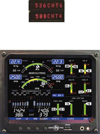
The EDM-960 is a combined electronic indicating system made up of one Display Unit and two Data Acquision Units one mounted behind each engine. Which displays to the pilot powerplant parameters. It replaces all previous primary digital and/or analog instruments: The display has a message area below the EGT/CHT”s Above are Abbreviation’s used in the Message Area, the parenthesis. (X)* denotes cylinder No.
Remote Alarm Display Operation (RAD)
The RAD is composed of two (one per engine) red 0.2” high by 8 character displays. The RAD displays flashing alert messages when any of the parameters reaches its preset trigger point, otherwise the RAD is dark. The RAD also serves as an alert back-up if the main LCD display screen becomes inoperative. The RAD will extinguish when no primary alarms exist or when the pilot acknowledges the alarm by tapping the STEP button on the EDM-960. On initial startup or whenever power is turned on, the words ‘EDM-960 PRIMARY’ are displayed, followed by the make and model of the aircraft for which the primary limits are set.

FAA Approved Installation Manual for the EDM-960 system Report No 909
Primary Engine Data Management System |
Page 5 of 46 Rev D |
|
Date 2-6-2014 |
Alarm hierarchy
When a measurement limit is reached, the pilot can momentarily tap the STEP button on the EDM-960 instrument to extinguish the particular flashing alarm acronyms. If another measurement has also reached its limit, that label will then begin to flash. The pilot should continue to monitor the affected parameters (just as he would using a conventional analog display that had reached a limit). The bar graph functions of CHT, EGT, and TIT remain displayed
for easy reference should one of these limits be reached. |
|
|
|
|
|||
1. |
OILP_LO. |
6. |
FLVL. |
11. |
CLD. |
16. |
AMPS. |
2. |
FP_LO. |
7. |
REM. |
12. |
RPM. |
17. |
CDT. |
3. |
OILT_HI. |
8. |
FP_HI. |
13. |
OILT_LO. |
18. |
RES. |
4. |
CHT. |
9. |
MAP. |
14. |
VOLTS. |
19. |
EGT. |
5. |
TIT. |
10. |
DIF. |
15. |
OILP_HI. |
20. |
Fuel Flow. |
6. Dimming
Automatic dimming is provided to dim both the panel display and the remote alarm display, RAD. Dimming can also be accomplished manually to change the Automatic setting. Tapping the third right button will bring up the Dim/Bright menu making the 3 and 4th button Dim or Bright in % Bright. Continuously holding this button increases brightness mode display.
Each EDM-950 has four mounting holes to mount to the avionics equipment rack or to the cold side of the firewall. The data ports are then connected to the display unit via a harness terminating at the EDM-930 display with a 25 pin D-Sub connector.
Remote Alarm Display PN 790749
DAU EDM-950 P/N 790000-B

FAA Approved Installation Manual for the EDM-960 system Report No 909
Primary Engine Data Management System |
Page 6 of 46 Rev D |
|
Date 2-6-2014 |
7. Locating and Installing the Indicator and Remote Alarm Display, RAD
A)The diagram below should be used as a guide for cutting and drilling the mounting and buttonholes in the instrument panel. The dimensions shown are for the final cutouts. Allow extra clearance for any panel finish such as powder coat. The plastic button caps are removable by grasping and pulling each off. The EDM-930 mounts in a 6x4.5 cutout. Mount the indicator using the figure below as a guide. If the panel has too many holes for a clean installation, it is recommended that an .10” aluminum overlay panel be constructed and installed over the original instrument panel and the EDM be installed into this overlay panel.
B)The Remote Alarm Display PN-790749 mounts in a 5/8 inch hole in the panel immediately above the Attitude Gyro / D.G. / HSI +/- 0.5 inches from their centerline directly in front of the pilot.
EDM-930/960 PANEL CUTOUT
FAA Approved Installation Manual for the EDM-960 system Report No 909
Primary Engine Data Management System |
Page 7 of 46 Rev D |
||
|
|
Date 2-6-2014 |
|
|
|
|
|
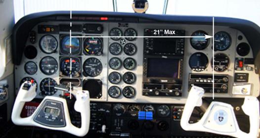
Figure 2: EDM-960 Mounting Area
8. EDM-960 Display Installation
Choose the Proper Installation Location
The display is best located within the natural scan and easy reach of the pilot. The recommended mounting location is defined as the distance from the vertical centerline of the Primary Flight Instruments to the outer edge of the further most gage displayed on the EDM-930.
HORIZONTAL ORIENTATION:
The EDM-960 display may be mounted from the vertical centerline of the Primary Flight
Instrument “T” to a maximum of 21” to the further most gage of the EDM-930 display and to the left of the centerline as much as needed. See fig 2
VERTICAL ORIENTATION:
The EDM-960 to be mounted within +/- 10” from the horizontal centerline of the Primary Flight Instrument “T”. The installer should insure that the EDM-960 display is not obstructed by either the glare shield or the control wheel.
The installing A&P and IA should decide that where the installation is to occur does not conflict with the viewing angle requirements listed above.
Note: Any appliances that are installed under the original Type Certificate (TC) that require relocation should be relocated in accordance with the guidance provided in AC.23.1311-1B, Section 15.4 (presented below). Special care should be exercised to insure that proper pilot visibility of displays and pilot access to controls in not interfered with, with respect to relocated instruments and non-relocated instruments.

FAA Approved Installation Manual for the EDM-960 system Report No 909
Primary Engine Data Management System |
Page 8 of 46 Rev D |
|
Date 2-6-2014 |
9. EDM-960 Key Card Installation
The EDM Key Card activates the primary engine instrument limits for you engine monitor. This key card contains the primary engine POH markings data. After installation do not remove the Key Card from the instrument. The key card is programmed with the serial number of your EDM and the make, model and year of your aircraft. Every time you power up the EDM, the Remote Auxiliary Display (RAD) will show your aircraft make and model in the right engine RAD. The Left RAD will display “EDM-960”
Each system is configured to a specific aircraft type. Therefore for example, a Cessna 310R would have a different series Part number than a Cessna 310Q.
Installation
With the EDM removed from the aircraft, position it on a flat surface with the rear of the instrument facing you as shown below. You do not have to remove any cables if you have sufficient service loop available. Follow the appropriate instructions below.
Open the small access door on the side of the
EDM-930/960 Display using the appropriate tool.
UP
KEY
CARD
Hold the Key Card so that the UP arrow is facing up and in insertion arrow is facing to the right.
Insert the Key Card in the guide rails until you feel it snap into place. Secure the access door.
Power up the EDM and confirm that your aircraft make and model is initially shown in the RAD upon power up. Install the EDM back into the aircraft. Your installation of the Key Card is complete.
If your EDM should ever have to be replaced with a unit with a different serial number, the factory will reprogram your Key Card to match the new serial number. You should always retain your fuel quantity calibration records, as these may need to be manually re-entered in a different or serviced unit.

FAA Approved Installation Manual for the EDM-960 system Report No 909
Primary Engine Data Management System |
Page 9 of 46 Rev D |
|
Date 2-6-2014 |
10. EDM-960 in aircraft with wing-mounted engines
Figure 1
RAD: Left/Right engine
Cockpit Display unit
Back of Display unit
FAA Approved Installation Manual for the EDM-960 system Report No 909
Primary Engine Data Management System |
Page 10 of 46 Rev D |
|
Date 2-6-2014 |
11. EDM-960 in aircraft with centerline thrust engines
FRONT/REAR engine RAD’s must be oriented top to bottom as shown below.
FRONT
REAR
EDM-960 centerline thrust display
FAA Approved Installation Manual for the EDM-960 system Report No 909
Primary Engine Data Management System |
Page 11 of 46 Rev D |
|
Date 2-6-2014 |
12. Wiring harness for 950
Five connectors are protruding from each of the two EDM-950 DAU’s, one for each engine. Connect the five wiring harnesses to the rear of the 950 DAU mounted on the cold side of the firewall and run the cables through the firewall into the engine compartment. Allow sufficient service loop to facilitate removal of the connectors for servicing. These wiring harnesses are labeled as follows:
EDM-950 |
Harness PN |
|
DAU |
|
Oil temperature, Induction temperature, Carburetor temperature, Outside air |
P1 |
790200 |
|
|
|
temperature, Turbine inlet temperature, Turbine inlet temperature 2, Engine ground. |
P2 |
700700 |
CHT, EGT 6 cylinder 10 feet |
|
700702 |
CHT, EGT 4 cylinder 10 feet |
P3 |
790422 |
RPM, MAP, Oil pressure |
P4 |
700708 |
Fuel flow transducers FX-201, GPS |
P5 |
790723 |
Fuel pressure , amperes, Voltage, and fuel level. |
P6 |
790827 |
Part of fuel qty sensor interface. Connects with J6 and P5 |
P7 |
790811 |
FQ, interface to Fuel tank. |
P8 |
790807 |
Power for, GPS , Aux Light to display on cockpit display |
Route the wires from the connectors through the firewall using fireproof rubber grommets and flame retarding silicone. Use an existing hole if possible. All wires must be routed away from high temperature areas (exhaust stacks, turbochargers, etc.). Secure probe and sensor leads to a convenient location on the engine approximately 8 to 12 inches from the probe or sensor, being sure there is sufficient slack to absorb engine torque. It is essential in routing the probe wire that this wire not be allowed to touch metal parts of the air-frame or engine since abrasion will destroy this high temperature wire. Secure wires along the route to the indicator. Secure wire using original clamps, tape or tie wrap if possible.
13. Wiring harness for Display
EDM-930 Display |
Harness PN |
Description |
|
|
|
LEFT/FRONT RAD |
790749 |
Category 5 jack and cable for RAD Right engine |
|
|
|
RIGHT/REAR RAD |
790749 |
Category 5 jack and cable for RAD Left engine |
|
|
|
P8 |
790807 |
25 pin D-Sub - GPS RS232, GND, Aux Tank Intfc. |
|
|
|
LEFT/FRONT ENGINE (P9) |
790808 |
Canon Plug (Installer wired) - Power, RS232 MFD data |
|
|
|
RIGHT/REAR ENGINE (P10) |
790808 |
Canon Plug (Installer wired) - Power, RS232 MFD data |
|
|
|
P9/P10 |
174203 |
Connector Lft/Rt Data (field installed to P11) |
P11 |
790808 |
Power DAU, Data for DAU |
P12 |
790810 |
Optional—Aux Light interface cable to J12 on P8 |
CAUTION: Be sure any wiring does not obstruct the control movement under the instrument panel.
The probe wires must not be tied in with ignition, alternator or engine cabin heater ignition wires because of potential interference with readings.
The temperature probe wiring harness is made of Chromel-Alumel alloy wires that must not be substituted or extended with copper wire. The power and ground wire are normal copper. Temperature probe leads may be spliced with additional Chromel-Alumel wire using copper butt splices.

FAA Approved Installation Manual for the EDM-960 system Report No 909
Primary Engine Data Management System |
Page 12 of 46 Rev D |
|
Date 2-6-2014 |
When the installation is complete all wires should be secured using ties and carefully checked for interference, rubbing or chafing with flight control cables or other moving parts.
14. Pressurized Aircraft wire Routing
Pressurized twin Engine Aircraft have a factory installed pressure bulkhead pass thru boot or connector at each wing root where all electrical wires from the engine pass through to the cockpit. If you can not find the opening follow the wires from the engine to the pressure vessel. If a boot with sealant is used remove the sealant, pass the three RS232 signal wires from the Data Acquisition Unit mounted in the engine compartment to the Display. Upon accomplishing this reseal the hole with factory recommended sealant.
An alternate method for a cannon connector is to use existing wires in the aircraft going thru the pressure bulkhead. The EDM-960 replaces the RPM, MAP, Oil Temperature, Oil Pressure and TIT gauges which have wires going thru the pressure bulkhead. Any combination of three wires can be used to transmit signal to the cockpit display. Making a new hole in the pressure bulkhead is beyond the scope of this document and will require a DER or other FAA
approval.
15. Power Connection
The EDM-960 automatically accommodates either a 14 or a 28-volt electrical system. Master Bus power must be individually provided, via three 5 amp circuit breakers, to the two DAU units and the EDM-960 head.
IMPORTANT: Insure the DAU ground wires are connected to the engine block. Any wiring extensions or additions beyond JPI supplied wiring must be MIL-W-32759/16 or equivalent. The EDM-960 has a 8-second warm-up. No connection to the aircraft dimmer system is required because the instrument dims automatically with reductions in ambient light. The instrument is designed to reset at less than 10 vdc bus power, therefore the instrument may reset on engine start (typical for 14 vdc systems). This is normal due to the starter loading down the battery output to below 10 vdc.
16. Probe Wiring
When cutting the pair of leads to the proper length to connect to the probes, leave enough slack in the wiring so that probe may be interchanged to an adjacent cylinder if necessary for trouble-shooting and servicing. Thermocouple wire length is not critical and should be trimmed to any length as required for a clean installation.
The Temperature probe must be wired with the correct polarity. The temperature probe connects to its temperature indicator with yellow jacket Teflon Chromel-Alumel wire supplied. Strip the wires as shown below—observing colorcoding.
Thermocouple wire harness
|
|
2 1/4" |
|
|
|
|
|
|
|
|
|
|
|
|||
|
|
|
|
|
yellow |
|
|
|
|
|
||||||
|
|
|
|
|
|
|
|
|
|
|
|
|
|
|||
|
|
|
|
|
|
|
|
|
|
|
|
|
Fold back wire |
|||
|
|
|
|
|
|
|
|
|
|
|
|
|
|
|
|
double before |
|
red |
|
|
|
|
|
|
|
|
|
|
|
|
|
|
crimping terminals |
|
|
|
|
1/4" |
|
|
|
1 1/2" |
|
|
|
|
|
|
||
|
|
|
|
|
|
|
|
|
|
|
||||||
Terminate each wire with a crimp-on ring terminal, provided. The ring terminals may be crimped with a “service-type” tool, however AMP part number 48518 crimp tool is recommended. Verify the quality of each crimp with a sharp tug on the wire. The terminal should be impossible to pull off when crimped correctly.
 ring terminal
shrink tubing
Place a ¼ x 4-inch sleeve over each pair of wires in the wiring. Connect the wire ring lug to the probe ring lug using the supplied number 4 screws and nuts, placing the star washer between the ring lugs, not against the nut.
|
|
|
Important: place star waster between two ring |
to instrument |
|
|
terminals and tighten nut and bolt as |
|
|
necessary |
|
|
|||
|
|
|
|
to probe

FAA Approved Installation Manual for the EDM-960 system Report No 909
Primary Engine Data Management System |
Page 13 of 46 Rev D |
|
Date 2-6-2014 |
Slide the sleeve over the joint and secure with three tie-wraps.
tie-wrap 3 places
1/4 x 4" sleeve
The most common installation problems are related to poor quality terminations.
17. Wiring Markings
The EDM-960 is supplied with special Teflon insulated Chromel Alumel factory assembled wiring harness configured for the correct number of cylinders. The wire harness is marked E1= EGT-1, C1= CHT-1, etc.
NOTE: Unlike most other EGT & CHT installations the probe wire length is not critical and should be trimmed to any length as required for a clean installation. Do not extend the thermocouple wire with copper wire.
18. Exhaust Gas Temperature Probe (EGT) Installation
Use the J2 connector harness 700700 or 700702 labeled E1 through E4 or E6. Remove the existing EGT gage and Probe. Replace with JPI probe M-111 in all exhaust stacks.
CHT probe
 stack exhaust


EGT probe Drill no. 40 pilot hole, then no. 30 hole.
2" to 4"
The Model M-111 Probe will fit any engines where the existing holes in the exhaust stack are 1/8" to 1/4" in diameter. If no hole exists, it will require the drilling of a 1/8" diameter hole and ream to fit. It is important that each probe be mounted the same distance from its exhaust stack flange. A nominal distance of 2 to 4 inches from the exhaust flange is recommended. If the recommended distance is impractical because of obstructions, slip joints or bends in the exhaust system then position the probes a uniform distance from the flange as space permits. Do not mount probes in slip joints. Be certain to locate all holes BEFORE drilling to ensure that nothing interferes with the probe, clamp, screw or wire. Careful matching of probe position will provide best temperature readings.
Insert the probe in the exhaust or previously drilled hole so that the tip of the probe is in the center of the exhaust stream. Tighten the stainless steel clamp to a torque of 45 in/Lbs. Cut off the excess strap close to the screw.

FAA Approved Installation Manual for the EDM-960 system Report No 909
Primary Engine Data Management System |
Page 14 of 46 Rev D |
|
Date 2-6-2014 |
Clamp |
|
Seal Washer |
|
Thimble |
Position probe |
note orientation of |
in approximate |
slot |
center of |
Probe |
exhaust |
RADIAL ENGINE EGT
Radial engine exhaust, require a larger EGT clamp (supplied) to fit the 2.5 inch exhaust pipe. The EGT probe is installed in the same fashion as a Lycoming or Continental engine and should be placed between the exhaust pipe flange and the accumulator at a distance of 2 to 3 inches form the engine exhaust flange. Cylinder head temperatures are measured with a spark plug gasket type probe placed under the front sparkplugs. Front spark plugs will read 15 to 20 degrees cooler than the rear plugs. Refer to the engine manufactures recommended location. Do not route the EGT/CHT harness in with the ignition harness. Do not extend the yellow thermocouple leads with copper wire.
19. Turbine Inlet Temperature (TIT) Probe Installation (optional)
Use the J1 connector harness 790200 and insert the yellow wire into the connector pin 16 and the red wire into pin 17. The standard TIT probe PN M111-T with a #48 clamp is placed in the exhaust stack accumulator to a maximum depth of 1/2 inch and approximately 4 inches from the turbine inlet if possible, on the waste-gate side of the turbine.
19.1 Using the Factory original TIT Probe
The factory installed TIT probe (K-calibration) is compatible with the JPI EDM-960 System. Connect the JPI wire marked TIT. Replacement probes should be purchased per part number from the aircraft manufacturer.
The EDM-960 permits you to remove the factory installed TIT indicator and leave the TIT probe installed. Connect the JPI wire marked TIT directly to the probe noting color polarity. The TIT probe should now have only the JPI leads attached to it. No calibration of the EDM-960 is necessary.
20. Cylinder Head Temperature (CHT) Probe Installation
Use the J2 connector harness 700700 or 700702 labeled C1 through C4 or C6. The JPI probe is a bayonet probe P/N 5050-T that has a captive 3/8-24 boss that is screwed into the head of each cylinder.
For Indicator replacement, replace your existing CHT probe and adapter, a bayonet or screw in type with one supplied by JPI. Install the probe on the same cylinder from which you removed the original equipment probe. Your current CHT probe is installed in the hottest cylinder as determined by the airframe manufacturer.
RADIAL ENGINE (CHT) SPARK PLUG GASKET
The spark plug gasket probe, P/N M-113, replaces the standard copper spark plug gasket on one spark plug. The probe is usually placed on the Rear plugs. After many removals the probe may be annealed for re-use. Heat to 1100 oF and quench in water.
 Loading...