


EDM-760 Quick Reference Guide
How to use LeanFind™ (page 13)
|
|
|
PEAKEGT |
|
Pre-lean |
TapLF |
Lean the |
Stopat |
Enrich to |
themixture |
button |
mixture |
peak |
peak or |
|
|
|
|
100° richof |
|
|
|
|
peak |
How to Change Modes (page 7)
EDM-760 enters Automatic indexing mode two minutes after power up
A U T O |
I N |
D |
E X |
: |
p a r a |
m e |
t e |
r s |
|
in d e x e d |
|
|
||
a u t o m a t i c a l ly |
|
|||
|
|
|
t a p |
|
|
t a |
p |
S T E |
P |
|
t a p S T |
E P b u t t o n |
||||||
t a p L F b u t t o n , t h e n S T E P |
||||||||
L F b u t t o n |
L E A |
N F I N D : |
||||||
b u t t o n |
|
s |
t a |
r t s |
|
|||
L |
e |
a |
n |
F |
in |
d |
||
|
||||||||
|
p |
r o |
c |
e |
d |
u |
r e |
|
M |
A N |
U A L |
||
|
I N D |
E |
X |
: |
p |
a r a m |
e |
t e |
r s |
in d e x e |
d |
w h e n |
||
b u t t o n |
S T E P is t a p p e d |
|
|
|
L F |
|
h o ld L F b u t t o n |
r e le a s e L F b u t t o n |
|
t a p
b o t h
S T E P a n d L F  s im u lt a n e o u s ly
r e |
le |
a |
s |
e |
|
|
b |
u |
t t o |
n |
s |
|
|
D is |
p |
la |
y |
s |
p e |
a k |
E |
G |
T |
|
v a lu |
e |
|
T |
o |
g g |
le |
|
i n |
c |
l u |
d |
e / |
e x |
c |
l u |
d |
e |
p a r a m |
e t e r i n |
in d e |
x i n g |
How to …
interpret CHT trends page 6
lean turbocharged engines page 19 diagnose engine problems page 23 calibrate OAT readings page 37 change from °F to °C page 37, 44 dump data to a PC page 36
reset an alarm page 26 set start up fuel page 29
accumulate total fuel page 30 reset fuel used page 30
set fuel tank capacity page 47 set K factor page 41
Note Tank size can be entered by holding in the step button upon start-up.
Specifications
FAA Approved
Indicator TSO & STC
Fuel Flow Option STC
Display Size:
3 1/8 in panel mount
3.5 in. sq., 7.5 in. deep
Common Mode Range:
+ 4v, rejection > 80db
Analog Thermocouples
Response curve: All Linearized. Resolution: 1.0 oF
Accuracy: + 1.0 oF
Calibration: type K (J CHT avail.)
Operating Temperature Range:
-40 to 195 oF
Temperature Range:
EGT bar graph: variable
EGT, TIT digital: -40 to 2500 oF CHT, OAT, IAT: -40 to 800 oF
Analog input channels:
12 Exhaust Gas Temperature (EGT)
12 Cylinder Head Temperature (CHT)
2 Turbine Inlet Temperature (TIT)
2 additional channels
(either OIL, CRB or second TIT) 1 Outside Air Temperature (OAT) 1 System Bus Voltage (BAT)
Resolution and Display Range (Fuel Flow Option)
display |
|
maximum display value |
|
resolution |
|
K factor range: |
5,000 to 99,990 |
10 |
|
||
Fuel flow: |
Accuracy (8 to 60 GPH) |
1 % |
|||
|
140.0 |
GPH at K factor 85,000 |
0.1 |
GPH |
|
|
410.0 |
GPH at K factor 29,000 |
0.1 |
GPH |
|
|
820 PPH at K factor 85,000 |
1 |
PPH |
||
|
2400 |
PPH at K factor 29,000 |
1 |
PPH |
|
|
560 LPH at K factor 85,000 |
1 |
LPH |
||
|
1640 |
LPH at K factor 29,000 |
1 |
LPH |
|
|
372 KPH at K factor 85,000 |
1 |
KPH |
||
Fuel Remaining: |
1088 |
KPH at K factor 29,000 |
1 |
KPH |
|
999.9 |
Gal |
0.1 |
Gal |
||
Fuel Used: |
999 Lbs., L, or Kg |
1 |
Lb., L, or Kg |
||
999.9 |
Gal. |
0.1 |
Gal |
||
Time to Empty: |
9999 |
Lbs., L, or Kg |
1 |
Lb., L, or Kg |
|
50 hours |
1 minute |
||||
Long Term Memory
Data capacity: up to 17 hours sampled every 6 seconds Recording rate: programmable, every 2 seconds to 500 seconds
Pilot’s Guide
EDM-760 TWIN
Copyright © 1999, 2001, 2003, 2004, 2005 J.P. Instruments, Inc.
All Rights Reserved
Printed in the United States of America
J.P.INSTRUMENTS
Information: P. O. Box 7033
Huntington Beach, CA 92646
Factory: 3185-B Airway Avenue Costa Mesa, CA 92626
(714) 557-5434 Fax (714) 557-9840 jpinstruments.com ,
JPITech.com and BUYJPI.com
Rev L
3/15/2012 13:29:00 a3/p3
Table of Contents
Section 1 - |
Introduction |
1 |
Section 2 - |
Displays and Controls |
4 |
Section 3 - |
Operating Procedures |
11 |
Section 4 - |
Diagnosing Engine Problems |
23 |
Fuel Flow Option Operation |
28 |
|
Long Term Memory |
34 |
|
Personalizing |
37 |
|
Fuel Flow Option—Formats, Diagnostics |
48 |
|
Section 5 - |
Option Connector Pin Assignments |
50 |
Reference Reading |
51 |
|
Section 6 - |
Technical Support |
51 |
Limited Warranty |
52 |
|
Index |
|
53 |
Section 1 - Introduction
Product Features
EDM-760 Standard Instrument:
∙Hands-free, automatic scanning
∙Bar graph
∙LeanFind™ mode
∙Battery voltage
∙Normalize view
∙DIF low to high EGT spread
∙Shows largest EGT variance
∙Oil temperature option
∙EGTs to 1°F resolution
∙Shock cooling monitoring
∙Outside air temperature (OAT) option
∙User selectable index rate
∙Alarm “red line” limits
∙Fast response probes
∙Real-time serial data port
Engine Data Management
Fuel Flow Option:
∙Solid-state pulse generating rotor fuel flow transducer
∙Fuel quantity measured in gallons, kilograms, liters, or pounds
∙Low fuel quantity alarm
∙Low fuel time alarm
∙GPS interface
∙Instantaneous fuel flow rate,
∙Total amount of fuel consumed,
∙Total fuel remaining, and
∙Time to empty at the current fuel flow rate.
Long Term Memory:
∙Records and stores data every 2 to 500 seconds
∙Non-volatile memory
∙Post-flight data retrieval
∙Data retrieval software
∙17 hours data capacity at 6 second sample rate
The EDM-760 Engine Data Management system is the most advanced and accurate piston engine monitoring instrument on the market. Using the latest microprocessor technology, the EDM-760 will monitor up to twenty-four critical measurements in your engines, three times a second, with a linearized thermocouple accuracy of better than 0.1 percent or 2°F.
As your built-in flight engineer, the EDM-760 is constantly “red line” checking: all critical measurements are automatically checked several times a second, regardless of the current display status. Leaning is
accomplished quickly and automatically using the LeanFind™ procedure.

With the EDM-760 it is now possible to have substantially more diagnostic information available to you in a timely and usable manner.
The included data memory permits you to record all measurements for later down loading to your laptop or Palm handheld.
Benefits of Proper Mixture Control
∙Improved engine efficiency
∙Greater fuel economy
∙Smoother engine operation
∙Longer spark plug life
JPI Probes
Temperature information processed by the EDM-760 is captured by fast response, grounded JPI temperature probes, that accurately measure the small temperature changes—as small as 1°F—that occur during mixture adjustment.
Temperature and Mixture
∙Reduced maintenance
costs
∙Reduced operating costs
∙Proper engine temperatures
∙Reduced engine vibration
|
CHT probe |
cylinder |
exhaust |
head |
manifold |
|
EGT probe |
In a piston engine only a small portion of the energy from combustion produces movement of the piston during the power stroke. The majority of energy passes into the exhaust pipe as hot gasses. By monitoring the temperature of these exhaust gasses you will have an indication of the quality of the combustion process. Low compression, non-uniform fuel distribution, faulty ignition, and clogged injectors diminish the efficiency of the combustion process that generates power.
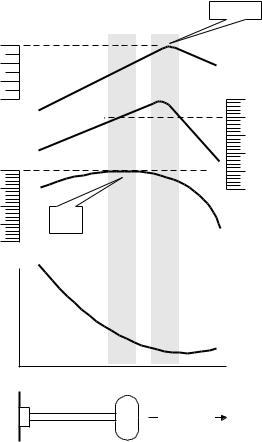
From the cockpit you can adjust the fuel/air ratio by a process called leaning. Retarding the mixture control changes the fuel/air ratio and hence the resulting Exhaust Gas Temperature (EGT).
The following figure depicts the mixture and temperature relationship.
Page 2 |
Engine Data Management |
0
|
-100 |
|
belowpeak |
-200 |
|
-300 |
||
EGT °F |
|
|
|
100 |
|
|
95 |
|
power |
90 |
|
85 |
||
of best |
||
80 |
||
Percent |
||
|
Best |
Best |
PeakEGT |
|
|
power |
economy |
|
|
|
|
|
|
||
range |
range |
|
|
|
T |
|
|
|
|
G |
|
|
|
|
E |
|
|
|
|
|
|
20 |
|
|
T |
|
0 |
|
|
|
|
|
|
|
CH |
|
-20 |
|
|
|
|
changefrom |
powerbest |
|
Percent power |
|
-40 |
||
|
|
|
||
|
|
|
|
|
|
|
-60 |
CHT °F |
|
|
|
-80 |
|
|
|
|
|
|
Peak
Power
|
S |
|
|
|
|
pe |
|
|
|
|
cific |
|
|
|
|
fu |
|
|
|
|
el |
|
|
|
|
c |
|
|
|
|
on |
|
|
|
|
|
su |
|
|
|
|
m |
|
|
|
|
p |
|
|
|
|
ti |
|
|
|
|
on |
|
|
Full Rich |
Rich |
|
Lean |
Too |
(Take-off) |
|
|
|
lean |
Leaner Mixture
As the mixture is leaned, EGT rises to a peak temperature, and then drops as the mixture is further leaned. Peak power occurs at a mixture using more fuel than at peak EGT. Best economy occurs at peak EGT. Accurate leaning yields optimal engine temperatures. By being able to precisely adjust the mixture, your engines can produce either the highest fuel economy or maximum power, whichever you choose.
A single EGT gauge merely gives you an average of each cylinder’s temperature: some cylinders can be too rich, while others too lean. Variations produced by differences in fuel distribution, ignition, and compression will cause each cylinder to follow its own mixture and temperature relationship such that one cylinder will reach peak before another.
For Your Safe Flight |
Page 3 |
Section 2 - Displays and Controls
The EDM-760 monitors engine temperatures and voltages, assists in adjusting the fuel/air mixture, and helps diagnose engine malfunctions. There are three components of the user interface:
∙Analog display including cylinder number and index dot
∙Digital display for numeric readouts and messages
∙Two front panel operating buttons.
Displays
Analog Display
The upper half of the face of the EDM-760 is the analog display.
D |
ig |
it a |
l |
|
t e m p e r a t u r e |
||||
in |
° F |
o r |
° C |
|
C |
H |
T |
s h o w n |
|
o |
n |
c a |
lib |
r a t e d |
s |
c a |
le |
|
|
E G T b a r g r a p h
r a |
n |
g e |
is |
|
||
8 |
2 |
5 |
° F |
( h |
a l f |
|
r e |
d |
lin |
e |
) |
t o |
|
1 |
6 |
5 |
0 |
° F |
|
|
D o t in d ic a t e s w h ic h |
|
|
|
|
N o r P |
|||||||||||||||||||||||||||||||
|
|
c y lin d |
e r t e m p |
e r a t u |
r e |
s |
|
|
|
|
|
|
|
in d |
||||||||||||||||||||||
|
|
|
|
|
a r e s h o w n in t h e |
|
|
|
|
|
|
|
|
|
|
N o r |
||||||||||||||||||||
|
|
|
|
|
|
|
|
ig it a l d is p la y |
|
|
|
|
|
|
|
|
|
|
P e r c |
|||||||||||||||||
|
|
|
|
|
|
|
|
|
|
|
|
|
|
|
|
|
|
|
|
|
|
|
|
|
|
|
|
|
|
|
P |
|
|
|
|
|
|
|
|
|
|
|
|
|
|
|
|
|
|
|
|
|
|
|
|
|
1 |
2 |
3 |
4 |
5 |
6 |
|
|
|
||||||||
C H |
T |
|
|
|
|
|
|
|
|
|
|
|
|
|
|
|
|
|
|
|
|
|
|
|
|
|
|
|
|
|
|
|
||||
5 0 |
0 |
|
|
|
|
|
|
|
|
|
|
|
|
|
|
|
|
|
|
|
|
|
|
|
|
|
|
|
|
|
|
|
|
|
|
|
|
|
|
|
|
|
|
|
|
|
|
|
|
|
|
|
|
|
|
|
|
|
|
|
|
|
|
|
|
|
|
|
|
|
|||
|
|
|
|
|
|
|
|
|
|
|
|
|
|
|
|
|
|
|
|
|
|
|
|
|
|
|
|
|
|
|
||||||
4 |
0 0 |
|
|
|
|
|
|
|
|
|
|
|
|
|
|
|
|
|
|
|
|
|
|
|
|
|
|
|
|
|
|
|
|
|
|
|
|
|
|
|
|
|
|
|
|
|
|
|
|
|
|
|
|
|
|
|
|
|
|
|
|
|
|
|
|
|
|
|
|
|
|||
|
|
|
|
|
|
|
|
|
|
|
|
|
|
|
|
|
|
|
|
|
|
|
|
|
|
|
|
|
|
|
|
|
|
|||
|
|
|
|
|
|
|
|
|
|
|
|
|
|
|
|
|
|
|
|
|
|
|
|
|
|
|
|
|
|
|
|
|
|
|||
|
|
|
|
|
|
|
|
|
|
|
|
|
|
|
|
|
|
|
|
|
|
|
|
|
|
|
|
|
|
|
||||||
3 0 0 |
|
|
|
|
|
|
|
|
|
|
|
|
|
|
|
|
|
|
|
|
|
|
|
|
|
|
|
|
|
|
|
|
|
|
||
|
|
|
|
|
|
|
|
|
|
|
|
|
|
|
|
|
|
|
|
|
|
|
|
|
|
|
|
|
|
|
|
|
|
|||
|
|
|
|
|
|
|
|
|
|
|
|
|
|
|
|
|
|
|
|
|
|
|
|
|
|
|
|
|
|
|
|
|
|
|||
|
|
|
|
|
|
|
|
|
|
|
|
|
|
|
|
|
|
|
|
|
|
|
|
|
|
|
|
|
|
|
||||||
|
|
|
|
|
|
|
|
|
I4 |
0 |
|
|
I |
|
E G T |
|
|
|
|
I4 |
5 |
|
|
|
|
|
||||||||||
|
|
|
|
|
|
|
|
3 9 0 |
|
|
C H |
T |
|
|
|
3 6 |
|
|
|
|
|
|
|
|||||||||||||
|
|
|
|
|
|
|
|
S T E P |
|
|
E D M |
- 7 6 |
0 |
|
|
|
|
|
|
|
|
|
|
|
|
|
|
|||||||||
|
|
|
|
|
|
|
|
|
|
J P I |
|
|
|
|
|
|
|
|
|
|
|
|
|
|
|
|||||||||||
|
|
|
|
|
|
|
|
|
|
|
|
|
|
|
|
|
|
|
|
|
|
|
|
|
|
|
|
|
|
|
|
|
||||
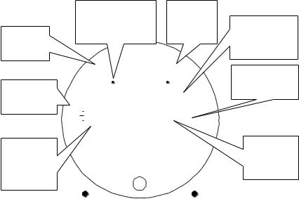
E x h |
a u |
s t G a |
s |
T e m p e r a t u r e |
|||
( E G T |
) is t h e t o p |
||
o f t h e |
c o lu m |
n |
|
C y |
lin |
d |
e |
r |
H |
e |
a d |
T e m p e r a t u r e |
|||||||
is |
s h |
o |
w |
n |
a |
s |
a |
m |
is |
s |
in |
g |
b |
a |
r |
The following is a description of the analog display, from top to bottom. Numbers in circles refer to features in the above diagram.
Temperature Units (°F or °C)
∙°F temperatures in the digital display are in Fahrenheit degrees.
∙°C temperatures in the digital display are in Celsius degrees.
Page 4 |
Engine Data Management |
To change the display of OAT see “Pilot Programming” on page 37. To change the display of engine temperatures see “Changing the Alarm Limits” on page 44.
Cylinder Numbers and Dot Index
A row of numbers 1 through 6 and the letter T are the column labels for the analog display. The 1 through 6 are the cylinder numbers. If the TIT option is installed, the T denotes the last column is displaying Turbine Input Temperature (TIT). If the T is absent and the Oil temperature option is installed, the last column displays Oil temperature. If both TIT and Oil temperature options are installed, the last column displays TIT and the missing segment displays OIL. A round dot under the numbers 1 through 6 indicates that particular column is shown numerically in the EGT and CHT digital display.
Normalize and Percentage View Indicators
∙Percentage view: when there is a P at the top of the display,
the columns indicate percent of EGT red line. Each column is composed of a stack of segments. A maximum height column depicts 100 percent of red line and a one segment-high column depicts 50 percent of red line. For example, if the red line is 1650°F, a maximum height column represents 1650°F and a one segment-high column represents half that value, or 825°F. The Percentage view permits comparison of EGTs across all cylinders. Hotter cylinders display higher columns than cooler cylinders.
∙Normalize view: when there is an N at the top of the display,
the EGT columns are displayed normalized. When you change to the Normalize view, all column peaks are set to the same half-height level for trend analysis. Any changes are shown as an increase or decrease in column height. A onesegment change in column height represents a 10°F change. The Normalize view permits rapid visualization of EGT trends, rather than a percentage of red line. You may use normalize in level cruise.
To toggle between Percentage and the Normalize views, hold the LF button for three seconds. The analog display becomes half height and the display changes to the Normalize view. Selecting the Normalize view does not affect the digital display nor alter the measurement sequence. The
For Your Safe Flight |
Page 5 |

CHT display—described later—is not affected by the Normalize or Percentage view.
You may select the Normalize view in either the Manual or Automatic indexing mode. Normalize view is most helpful for engine trend monitoring of each cylinder’s operation. For example using the Normalize view during engine run-up, a fouled spark plug will appear as a higher column.
A common mistake is to be in the Normalize view and then change your power setting, causing all columns to go off scale, high or low. Set to the Percentage view before adding or reducing power. Always set Percentage View when beginning your descent.
Bar Graph EGT and CHT
Each column in the bar graph is composed of a stack of segments. The total height of each column represents the EGT and the missing segment in the column represents the CHT trend.
∙ In the Percentage view, the EGT and TIT (or
Oil temperature) columns’ resolutions depend on the programmed red line limits.
C H T
5 0 0
4 0 0
∙ CHT is displayed by a missing segment or a |
3 |
0 |
0 |
single isolated lighted segment, in 25°F increments. The CHT display is the not affected by mode or view.
Digital Display
Beneath the bar graph is the 9-segment alphanumeric display.
EGT and CHT
When the dot index is beneath a cylinder number, 1 through 6, the digital display shows the EGTs on the top (four digits for each engine) and the CHTs on the bottom (three digits for each engine). Other measurements are displayed in the digital display as described in the subsection “Measurement Indexing—without Fuel Flow Option” on
page 10.
Page 6 |
Engine Data Management |
C |
H |
T |
|
s h o w n |
||||||
o |
n |
|
c |
a |
|
lib |
r a |
t e d |
||
s |
c |
a |
le |
|
|
|
|
|
|
|
|
|
|
4 |
|
|
d |
ig |
it |
|
|
|
|
d |
is |
p |
la y |
o |
f |
|||
|
|
|
|
E |
G |
T |
|
|
||
|
L |
e |
f t |
|
E n g in e |
|||||
3 |
|
d |
ig |
|
it |
d |
is |
p |
la y |
|
|
|
|
o |
f |
|
C |
H |
T |
|
|
|
L |
e |
f t |
|
E |
n |
g |
in |
e |
|
Display Dimming
|
|
|
|
|
|
° |
|
F |
|
|
|
L |
|
|
R |
P |
||||||||||||||||||
|
|
1 |
2 |
3 4 |
|
5 |
|
6 T |
1 |
2 3 4 |
|
5 6 T |
||||||||||||||||||||||
|
|
|
|
|
|
|
|
|
|
|
|
|
|
|
|
|
|
|
|
|
|
|
|
|
|
|
|
_ |
||||||
H |
T |
|
|
|
|
|
|
|
|
|
|
|
|
|
|
|
|
|
|
|
|
|
|
|
|
|
|
|
|
|
|
|||
5 |
0 0 |
|
|
|
|
|
|
|
|
|
|
|
|
|
|
|
|
|
|
|
|
|
|
|
|
|
|
|
|
|
|
|
|
|
|
|
|
|
|
|
|
|
|
|
|
|
|
|
|
|
|
|
|
|
|
|
|
|
|
|
|
|
|
|
|
|
|||
|
|
|
|
|
|
|
|
|
|
|
|
|
|
|
|
|
|
|
|
|
|
|
|
|
|
|
|
|
|
|
|
|||
|
|
|
|
|
|
|
|
|
|
|
|
|
|
|
|
|
|
|
|
|
|
|
|
|
|
|
|
|
|
|||||
4 0 |
0 |
|
|
|
|
|
|
|
|
|
|
|
|
|
|
|
|
|
|
|
|
|
|
|
|
|
|
|
|
|
|
|
|
|
|
|
|
|
|
|
|
|
|
|
|
|
|
|
|
|
|
|
|
|
|
|
|
|
|
|
|
|
|
|
|
|
|||
|
|
|
|
|
|
|
|
|
|
|
|
|
|
|
|
|
|
|
|
|
|
|
|
|
|
|
|
|
|
|
|
|||
|
|
|
|
|
|
|
|
|
|
|
|
|
|
|
|
|
|
|
|
|
|
|
|
|
|
|
|
|
|
|||||
3 0 0 |
|
|
|
|
|
|
|
|
|
|
|
|
|
|
|
|
|
|
|
|
|
|
|
|
|
|
|
|
|
|||||
|
|
|
|
|
|
|
|
|
|
|
|
|
|
|
|
|
|
|
|
|
|
|
|
|
|
|
|
|
|
|
||||
|
|
|
|
|
|
|
|
|
|
|
|
|
|
|
|
|
|
|
|
|
|
|
|
|
|
|
|
|
|
|
||||
|
|
|
|
|
|
|
|
|
|
|
|
|
|
|
|
|
|
|
|
|
|
|
|
|
|
|
|
|
||||||
|
|
|
|
|
I4 |
0 |
0 |
I |
|
E |
G T |
|
|
I4 5 2 |
||||||||||||||||||||
|
|
|
|
|
|
3 9 |
|
|
|
C H |
T |
3 6 |
3 |
|
|
|
||||||||||||||||||
|
|
|
|
|
|
|
S |
T E P |
|
|
|
|
E D M - 7 6 |
0 |
|
|
|
|
|
|
|
L F |
||||||||||||
|
|
|
|
|
|
|
|
|
|
|
J P I |
|
|
|
|
|
|
|
|
|
|
|||||||||||||
|
|
|
|
|
|
|
|
|
|
|
|
|
|
|
|
|
|
|
|
|
|
|
|
|
|
|
|
|
|
|
|
|
||
|
|
4 |
|
d |
ig |
it |
|
|
|
d |
is |
p |
la y |
|
o f |
|
|
|
|
|
E |
G |
T |
|
|
|
R |
ig h |
t |
E |
n |
g |
in |
e |
|
3 |
d |
ig |
it |
d |
is |
p |
la |
y |
|
|
o f |
C |
H |
T |
|
|
|
R |
ig |
h |
t |
E |
n |
g |
in |
e |
The entire display panel features automatic dimming. Allow ten seconds for the display to adjust to ambient lighting conditions.
Modes
There are three standard operating modes of the EDM-760: Automatic indexing, Manual indexing, and LeanFind. These modes will be described in more detail beginning on page 11. Most of the time you will operate the EDM-760 in the Automatic indexing mode. When you first turn on the power the EDM-760 starts in the Manual indexing mode, but will enter the Automatic indexing mode after two minutes. The three modes affect primarily the digital display.
Automatic Indexing Mode
Just tap the LF button, then tap the STEP button. No user intervention is required to use this mode. Each cylinder and each measurement value is automatically sequenced and shown in the digital display for a few seconds.
Manual Indexing Mode
Just tap the STEP button. Automatic Indexing stops. Each indexed measurement is frozen in the digital display until you manually index to the next measurement by tapping the STEP button.
For Your Safe Flight |
Page 7 |
LeanFind Mode
Simply pre-lean, tap the LF button and begin leaning. The EDM-760 will assist you in finding the first cylinder to peak.
Buttons
Buttons, Front Panel
Two operating buttons control all functions of the EDM-760.
The term tap will be used to denote pressing a button momentarily. The term hold will be used to denote pressing and holding a button for five seconds or longer.
STEP Button
Located on the lower left side near the instrument face.
∙In the Automatic indexing mode, tapping the STEP button will
stop indexing and change to the Manual indexing mode. Then each tap of the STEP button will display the next measurement in the sequence.
∙In the LeanFind mode tapping the STEP button will terminate the LeanFind mode and change to the Automatic indexing mode.
Secondary functions of the STEP button include:
∙In the Manual indexing mode holding the STEP button will
display the previous measurements in the sequence (rapidly backwards).
∙In the programming procedures, described on page 37, tapping the STEP button will advance to the next item in the list.
∙When an alarm is displayed (“Alarms” are described on page 43),
tapping the STEP button will temporarily delete that measurement from the sequence for the next ten minutes.
∙When an alarm is displayed, holding the STEP button until the
word OFF appears will delete that measurement from the sequence for the remainder of the flight.
Page 8 |
Engine Data Management |

LF Button
Located on the lower right side near the instrument face.
∙In Automatic or Manual indexing modes, tapping the LF button will change to the LeanFind mode.
∙In Automatic or Manual indexing modes holding the LF
button for three seconds will toggle between Percentage and Normalize views.
P:Percentageview |
holdLFbutton |
N: Normalize view |
|
for 3 seconds |
|||
|
|
∙In the LF mode holding the LF button after peak EGT is found will display peak EGT.
∙In the LF mode tapping the LF button twice will mark a data record in memory.
Secondary functions of the LF button include:
∙In the pilot programming procedure, holding or tapping the
LF button is used to increment or decrement parameter values and toggle between yes and no answers to questions.
STEP and LF Buttons
∙Holding both the STEP and LF buttons simultaneously for five seconds changes to the pilot programming procedure.
∙Holding both the STEP and LF buttons simultaneously for
five seconds after tapping LF but before beginning to lean will toggle between Rich of Peak and Lean of Peak
∙Tapping both the STEP and LF buttons simultaneously in
Manual indexing mode toggles to include or exclude the displayed measurement from the Automatic indexing mode. It has no affect on the displayed measurements in the Manual indexing mode.
For Your Safe Flight |
Page 9 |

Measurement Indexing—without Fuel Flow Option
The EDM-760 steps through the engine measurements in a specific sequence. Listed below is the indexing sequence, measurement description and example of the digital display.
|
Measurement |
Example |
Comments |
|
|
Voltage, System Bus |
I4.2 |
Battery voltage and OAT °F |
|
|
Outside Air |
8I BAT |
or °C |
|
|
Temperature |
OAT |
|
|
|
|
|
|
|
|
|
|
|
|
|
Difference between |
80 EGT |
Dot indicates most widely |
|
|
hottest and coolest |
52 |
deviating cylinder |
|
|
|
|
||
|
EGT |
DIF |
|
|
|
|
|
|
|
|
|
DIF |
|
|
|
|
|
|
|
|
EGT, CHT |
I340 |
EGT, left, CHT, right. Dot |
|
|
|
I430 |
indicates cylinder |
|
|
|
376 |
|
|
|
|
385 |
|
|
|
TIT, Turbine Inlet |
I370 |
|
|
|
Temperature |
I450 |
|
|
|
|
TIT |
|
|
|
|
TIT |
|
|
|
|
|
|
|
|
Oil Temperature |
I 7 7 |
|
|
|
|
I80 |
|
|
|
|
OIL |
|
|
|
|
OIL |
|
|
|
|
|
Only one of these three |
|
|
TIT #2 Second Turbine |
I450 |
|
|
|
Inlet Temperature |
I460 |
options may be installed in |
|
|
|
the aircraft |
|
|
|
|
T I2 |
|
|
|
|
|
|
|
|
|
T I2 |
|
|
|
|
|
|
|
|
Carburetor Temperature |
20 |
|
|
|
|
25 |
|
|
|
|
CRB |
|
|
|
|
CRB |
|
|
|
|
|
|
|
Page 10 |
Engine Data Management |
|||

|
|
|
Shock Cooling |
-30 |
Dot indicates fastest |
|
-40 |
cooling cylinder |
|
CLD |
|
|
CLD |
|
The display will pause at each measurement for four seconds in the Automatic indexing mode. (The four second indexing rate can be changed. See “Pilot Programming” on page 37.) In the Manual indexing mode, tap the STEP button to advance to next measurement. Only the measurements for the options that are installed will be displayed; uninstalled measurements will not appear.
Section 3 - Operating Procedures
Diagnostic Testing on Startup and During Flight
When your EDM-760 is first turned on, all digits light up for a few seconds, permitting you to check for non-functional segments. Then each column is self-tested in sequence while the EDM-760 tests internal
components, calibration and integrity of the probes. If a problem is found, it will be displayed as OPEN PRB or CAL ERR, followed by the name
of the probe or channel. During flight, probes are constantly checked for inconsistent or intermittent signals. A faulty channel or probe encountered during start-up or during flight will be deleted from the sequence, producing a missing column or blank digital data.
Modes
The EDM-760 has three different operating modes: Automatic indexing, Manual indexing and LeanFind. When you first turn on the power the EDM-760 starts in the Manual indexing mode, but will enter the Automatic indexing mode after a few minutes. The Automatic indexing mode provides you with engine monitoring information for the majority of flight conditions. To adjust the mixture, use the LeanFind mode. And to display specific measurements, use the Manual indexing mode. In both the Automatic and Manual indexing modes the analog display shows a bar graph of EGT and CHT for each cylinder and the TIT, if installed (or Oil temperature, if it is installed and TIT is not installed).
For Your Safe Flight |
Page 11 |
Automatic Indexing Mode
Just tap the LF button, then tap the STEP button. No user intervention is required to use this mode. In the Automatic indexing mode the EDM760 displays the measurement sequence at a user-selected indexing rate (see “Personalizing” on page 37).
Individual measurements can be excluded from the Automatic indexing mode: tap STEP to enter the Manual indexing mode. Tap STEP to index to the measurement you want to exclude. Then tap both the STEP and LF buttons simultaneously. Excluded measurements display a decimal point before the measurement name.
For example: |
↓ |
|
|
Included I84 OIL |
Excluded I84 OIL |
Tapping the STEP and LF buttons simultaneously will toggle back and forth between include and exclude.
∙You can program whether every time you turn on the EDM-760, it
will remember which measurements were excluded or defaults to none excluded. See on page 45.
∙All installed measurements are always displayed in the Manual
indexing mode. Exclusion only applies to the Automatic indexing mode.
∙All measurements are checked for alarm conditions every second regardless of their included or excluded status.
Manual Indexing Mode
Just tap the STEP button. Use the Manual indexing mode when you want to monitor one specific measurement such as shock cooling during descent, or a particular cylinder temperature during climbs. To change to the Manual indexing mode, tap the STEP button once. Subsequent taps will index the digital display through the measurement sequence (see “Measurement Indexing—without Fuel Flow Option” on page 10). To exit the Manual indexing mode and return to the Automatic indexing mode, either tap the LF button and then tap the STEP button (see “How
Page 12 |
Engine Data Management |
to Change Views” in the front of this manual). You may disable the Automatic indexing mode. See “Personalizing” on page 37.
LeanFind Mode—Leaning Rich of Peak
∙JPI’s EDM-760 provides two methods of leaning: lean
rich of peak (LEAN R) or lean of peak (LEAN L). The standard method is to lean about 20° rich of peak. With the advent of GAMI injectors it is now possible to set the mixture lean of peak—saving fuel and running the engine cooler. Teledyne Continental recommends lean of peak for the Malibu. This manual primarily describes the rich of peak method, and provides the procedure for the lean of peak method. The factory default method is set to rich of peak, but you can change this to lean of peak. See Changing the Alarm Limits Procedure on page 45.
Simply pre-lean, tap the LF button and begin leaning. Upon reaching cruise configuration, you will use the LeanFind mode to identify the first cylinder to reach peak EGT.
A more detailed explanation of the LeanFind procedure follows this step- by-step procedure.
For Your Safe Flight |
Page 13 |
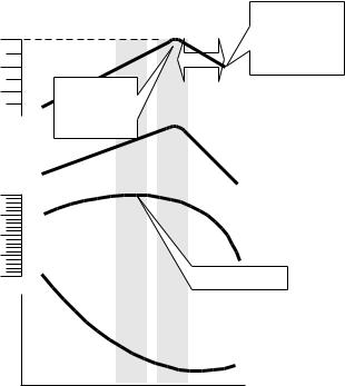
EGT °F below peak
Percent of best power
0
-50
-100
100
95
90
85
80
Best |
Best |
Last |
cylinderto |
power |
economy |
||
range |
range |
peak.Usefor |
|
LeanofPeak leaningwithGAMI injectors
|
|
|
|
T First cylinderto |
|
|
|
|
|
|
|
|
|
|
|
|
|
|
|
|
GAMI |
|
|||||||||||||||||||||||
|
|
|
|
|
|
|
|
|
|
|
|
|
|
|
|
|
|
|
|
spread |
|
||||||||||||||||||||||||
|
G |
|
peak. Usefor |
|
|
|
|
|
|
|
|
|
|
|
|
|
|
|
|
|
|
|
|
||||||||||||||||||||||
E |
|
|
|
|
|
|
|
|
|
|
|
|
|
|
|
|
|
|
|
|
|
|
|
|
|
|
|
|
|
|
|
|
|
|
|
|
from |
||||||||
|
|
|
|
|
|
|
RichofPeak |
|
|
|
|
|
|
|
|
|
|
|
|
|
|
|
|
|
|
|
|
|
|
|
|
|
|
|
|
|
|
20 |
|
||||||
|
|
|
|
|
|
|
leaning |
|
|
|
|
|
|
|
|
|
|
|
|
|
|
|
|
|
|
|
|
|
|
|
|
|
|
|
|
|
|
|
|
|
|
0 |
change°F powerbest |
||
|
|
|
|
|
|
|
|
|
|
|
|
|
|
|
|
|
|
|
|
|
|
|
|
|
|
|
|
|
|
|
|
|
|
|
|
|
|
|
|||||||
|
|
|
|
|
|
|
|
|
|
|
|
|
|
|
|
|
|
|
|
|
|
|
|
|
|
|
|
|
|
|
|
|
|
|
|
|
|
|
|
|
|||||
|
|
|
|
|
|
|
|
|
|
|
|
|
|
|
|
|
|
|
|
|
|
|
|
|
|
|
|
|
|
|
|
|
|
|
|
|
|
|
|
||||||
|
|
|
|
|
|
T |
|
|
|
|
|
|
|
|
|
|
|
|
|
|
|
|
|
|
|
|
|
|
|
|
|
|
|
|
|
|
|
|
|
|
-20 |
||||
|
|
|
|
|
|
|
|
|
|
|
|
|
|
|
|
|
|
|
|
|
|
|
|
|
|
|
|
|
|
|
|
|
|
|
|
|
|
|
|
||||||
|
|
|
|
|
|
|
|
|
|
|
|
|
|
|
|
|
|
|
|
|
|
|
|
|
|
|
|
|
|
|
|
|
|
|
|
|
|
|
|
||||||
|
|
|
|
|
|
|
|
|
|
|
|
|
|
|
|
|
|
|
|
|
|
|
|
|
|
|
|
|
|
|
|
|
|
|
|
|
|
|
|
|
|||||
|
|
|
|
|
|
|
|
|
|
|
|
|
|
|
|
|
|
|
|||||||||||||||||||||||||||
|
|
|
|
|
|
|
|
|
|
|
|
|
|
|
|
|
|
|
|
|
|
|
|
|
|
|
|
|
|
|
|
|
|
|
|
|
|
|
|
|
|
||||
|
|
|
|
|
H |
|
|
|
|
|
|
|
|
|
|
|
|
|
|
|
|
|
|
|
|
|
|
|
|
|
|
|
|
|
|
|
|
|
|
|
|
|
|
||
|
|
C |
|
|
|
|
|
|
|
|
|
|
|
|
|
|
|
|
|
|
|
|
|
|
|
|
|
|
|
|
|
|
|
|
|
|
|
|
|
|
-40 |
|
|||
|
|
|
|
|
|
|
|
|
|
|
|
|
|
|
|
|
|
|
|
|
|
|
|
|
|
|
|
|
|
|
|
|
|
|
|
|
|
|
|
|
|
|
|
|
|
|
|
|
|
|
|
|
|
|
|
|
|
|
|
|
|
|
|
|
|
|
|
|
|
|
|
|
|
|
|
|
|
|
|
|
|
|
|
|
|
|
|
|
|
|
|
|
|
|
|
|
|
|
|
|
|
|
|
|
|
|
|
|
|
|
|
|
|
|
|
|
|
|
|
|
|
|
|
|
|
|
|
|
|
|
|
|
|
|
|
-60 |
CHT |
|
|
|
|
|
|
|
|
|
|
|
|
|
|
|
|
|
|
|
|
|
|
|
|
|
|
|
|
|
|
|
|
|
|
|
|
|
|
|
|
|
|
|
|
||
|
|
|
|
|
|
|
|
|
|
|
|
|
|
|
|
|
|
|
|
|
|
|
|
|
|
|
|
|
|
|
|
|
|
|
|
|
|
|
|
|
|
|
|
||
|
|
|
|
|
|
|
|
|
|
|
|
|
|
|
|
|
|
|
|
|
|
|
|
|
|
|
|
|
|
|
|
|
|
|
|
|
|
|
|
|
|
|
|
||
|
|
|
|
|
|
|
|
|
|
n |
|
|
|
|
|
|
r |
|
|
|
|
|
|
|
|
|
|
|
|
|
|
|
|
|
|
|
|
|
|
|
|||||
|
|
|
|
|
|
|
|
|
|
|
|
|
|
|
|
|
|
|
|
|
|
|
|
|
|
|
|
|
|
|
|
|
|
|
|
|
|
|
|
||||||
|
|
|
|
|
|
|
|
|
|
|
|
|
|
|
|
|
|
|
|
|
|
|
|
|
|
|
|
|
|
|
|
|
|
|
|
|
|
|
|
|
|
|
|
||
|
|
|
|
|
|
|
|
|
|
|
|
|
|
|
|
|
|
|
|
|
|
|
|
|
|
|
|
|
|
|
|
|
|
|
|
|
|
|
|
|
|
|
|
||
|
|
|
|
|
|
|
|
|
|
|
|
|
|
|
|
|
e |
|
|
|
|
|
|
|
|
|
|
|
|
|
|
|
|
|
|
|
|
|
|
|
|
|
|||
|
|
|
|
|
|
|
|
|
|
|
|
|
|
|
w |
|
|
|
|
|
|
|
|
|
|
|
|
|
|
|
|
|
|
|
|
|
|
|
|
|
|
|
|||
|
|
|
|
|
|
|
|
|
|
|
|
|
|
o |
|
|
|
|
|
|
|
|
|
|
|
|
|
|
|
|
|
|
|
|
|
|
|
|
|
|
|
|
|
|
|
|
|
|
|
|
|
|
|
e |
tp |
|
|
|
|
|
|
|
|
|
|
|
|
|
|
|
|
|
|
|
|
|
|
|
|
|
|
|
|
|
|
|
|||||
|
|
|
|
|
|
rc |
|
|
|
|
|
|
|
|
|
|
|
|
|
|
|
|
|
|
|
|
|
|
|
|
|
|
|
|
|
|
|
|
|
|
|
|
|||
|
|
|
|
|
e |
|
|
|
|
|
|
|
|
|
|
|
|
|
|
|
|
|
|
|
|
|
|
|
|
|
|
|
|
|
|
|
|
|
|
|
|
|
|
||
|
|
|
P |
|
|
|
|
|
|
|
|
|
|
|
|
|
|
|
|
|
|
|
|
|
|
|
|
|
|
|
|
|
|
|
|
|
|
|
|
|
|
|
|
||
Peak Power
|
S |
|
|
|
|
|
p |
|
|
|
|
e |
|
|
|
|
c |
|
|
|
|
i |
|
|
|
|
fi |
|
|
|
|
c |
|
|
|
|
f |
|
|
|
|
u |
|
|
|
|
e |
|
|
|
|
l |
|
|
|
|
c |
|
|
|
|
o |
|
|
|
|
|
n |
|
|
|
|
s |
|
|
|
|
u |
|
|
|
|
m |
|
|
|
|
p |
|
|
|
|
t |
|
|
|
|
i |
|
|
|
|
o |
|
|
|
|
n |
|
Full Rich |
Rich |
Lean |
|
Too |
(Take-off) |
|
|
|
lean |
Page 14 |
Engine Data Management |
 Loading...