

Page 1

Operator’s manual
Manual d’utilisation
Manual de instrucciones
EN (2-30)
FR (31-60)
ES (61-90)
Please read these instructions and make sure you understand them before using the machine.
Lire attentivement et bien assimiler le manuel d’utilisation avant d’utiliser la machine.
Lea detenidamente el manual de instrucciones y asegúrese de entender su contenido antes de utilizar la máquina.
Page 2

E n g l i s h --- 2
115305026 Rev. 3 7/15/10
SYMBOL EXPLANATION
This product is in accordance
with applicable EC directives.
Noise emission to the
environment according to the
European Community’s
Directive. The machine’s
emission is specified in the
T echnical data section and
on label.
Sound pressure level at
7,5 metres.
Use unleaded or quality leaded
petrol and two--stroke oil
mixed at a ratio of 2% (1:50).
Other symbols/decals on the machine
refer to special certification requirements
for certain markets.
Stop the engine by pushing
and holding the stop switch
in the STOP position. CAUTION!
The stop switch automatically
returns to the start position.
In order to prevent unintentional
starting, the spark plug cap must be
removed from the spark plug when
assembling, checking and/or
performing maintenance.
Regular cleaning is required.
Visual check.
Approved eyeprotection must
always be used.
Symbols
WARNING: Clearingsaws, brush-
cutters an dtrimmers can be dangerous! Careless or incorrect use
can result inserious or fatal
injury to the operator or others.
Please read the operator’s manual
care fully andmake sure you
understand the instructions
before using the machine.
Always wear:
S A protective helmet where there
is a risk of falling objects
S Hearing protection
S Approved eye protection
Max. speed ofoutput shaft, rpm
Beware of thrown objects and
ricochets.
The operator of themachine
shall ensure, while working,
that no persons or animals
come closer than 15 metres.
Machines fitted with grass blades
can be thrownviolently tothe side
when the blade comes into contact
with a fixed object. The blade is
capable of amputating an arm or
leg. Always keep people and
animals at least 15 metres from
the machine.
Arrows which show limits for
handle mounting.
Always wear approved protective
gloves.
Use anti--slip andstableboots.
Only usenon--metallic, flexible
cutting attachments, i.e. trimmer
heads with trimmerline.
Page 3

E n g l i s h --- 3
115305026 Rev. 3 7/15/10
CONTENTS
Contents
KEY TO SYMBOLS
Symbols 2.........................
CONTENTS
Contents 3........................
Note the following before starting 3....
WHAT IS WHAT?
What is what? 4...................
GENERAL SAFETY PRECAUTIONS
Important 5........................
Personal protective equipment 5......
Machine’s safety equipment 6........
Cutting equipment 8.................
ASSEMBLY
Fitting the handlebar 11...............
Fitting the harness 11................
Fitting blades and trimmer heads 12....
Fitting a blade guard, grass blade and
grass cutter 12......................
Fitting the blade guard andsaw blade 13
Fitting the trimmer guardand
trimmer head 13.....................
FUEL HANDLING
Fuel safety 14.......................
Fuel 14............................
Fueling 15..........................
STARTING AND STOPPING
Check before starting 16..............
Starting and stopping 16..............
WORKING TECHNIQUES
General working instructions 18........
MAINTENANCE
Carburetor 23.......................
Muffler 24..........................
Spark plug 24.......................
Air filter 25..........................
Bevel gear 25.......................
Maintenance schedule 26.............
TECHNICAL DATA
Technical data 27....................
EC--declaration of conformity
(Applies to Europe only) 28............
Note the following before
starting:
Please read the operator’s manual carefully.
Jonsered has a policy of continuous product
development and therefore reserves the right
to modify the design and appearance of
products without prior notice.
WARNING: A clearing saw,
brushcutter or trimmer can be
dangerous if used incorrectly or
carelessly, and can cause serious
or fatal injury to the operator or
others. It isextremely important
that you read and understand the
contents of this operator’s manual.
WARNING: Under no circum-
stances may the design of the
machine be modified without the
permissionof the manufacturer.
Always use genuine accessories.
Non--authorized modifications
and/or accessories can result
in serious personal injury or the
death of the operator or others.
WARNING: Long--term exposure
to noise can result in permanent
hearing impairment. So always use
approved hearing protection.
Page 4
E n g l i s h --- 4
115305026 Rev. 3 7/15/10
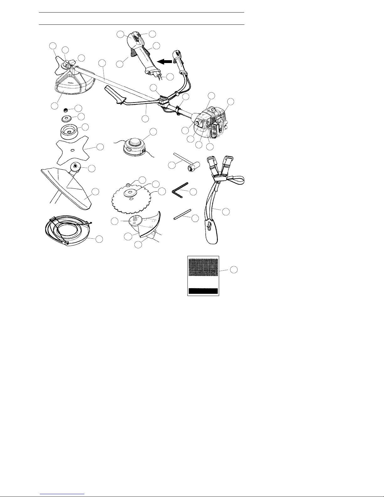
WHAT IS WHAT?
5
2
9
10
6
16
21
23
25
1
3
8
11
15
13
14
7
12
30
17
4
4
4
27
22
18
19
20
1
21
24
29
28
26
31
18
32
33
1. Grass blade 18. Locking nut
2. Grease filler cap 19. Support flange
3. Bevel gear 20. Support cup
4. Cutting attachmentguard 21. Drive disc
5. Shaft 22. Trimmer head
6. Handlebar 23. Socket spanner
7. Throttle control 24. Transport guard
8. Stop switch 25. Hex wrench
9. Throttle lock--out 26. Locking pin
10. Harness clamp 27. Harness
11. Cylinder cover 28. Start throttlebutton
12. Starter handle 29. Adjusting the throttle wire
13. Fueltank 30. Saw blade
14. Choke control 31. Mounting plate/adapter
15. Primer bulb 32. Support flange
16. Air filter cover 33. Operator’s manual
17. Handle adjustment
What is what?
Page 5
E n g l i s h --- 5
115305026 Rev. 3 7/15/10
GENERAL SAFETY PRECAUTIONS
IMPORTANT!A clearing saw, brushcutter
or trimmer can be dangerous if used incorrectly or carelessly, and can cause serious
or fatal injury to the operator or others. It is
extremely important that you read and understand the contents of this operator’s
manual. You must use approved personal
protective equipment whenever you use the
machine. Personal protective equipment
cannot eliminate the risk of injury but it will
reduce the degree of injury if an accident
does happen. Ask your dealer for help in
choosing the right equipment.
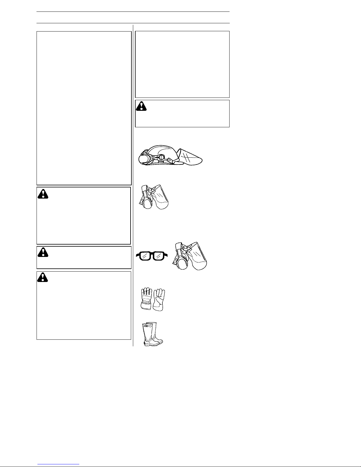
HELMET
A helmet should beworn ifthe brush being
cleared is taller than 2metres.
HEARING PROTECTION
Wear hearing protection that provides
adequate noise reduction.
EYE PROTECTION
Always wear approved eye protection. If
you use avisor then you must also wear
approved protective goggles. Approved
protective goggles must comply with EN
166 in EU countries.
GLOVES
Gloves should be worn whennecessary,
e.g., when fitting cutting attachments.
BOOTS
Wear sturdy, non--slipboots.
Personal protective equipment
WARNING: Listen out for warn-
ing signals or shouts when you are
wearing hearing protection. Always
remove your hearing protection as
soon as the engine stops.
Important
IMPORTANT! The machine is only designed
for trimming grass, grass clearing and/or
forestry clearing. The only accessories you
can operate with this engine unit are the cutting attachments we recommend in the section
on Technical data. Never use the machine if
you are tired, if you have drunk alcohol, or if
you are taking medication that could affect
your vision, your judgement or your co--ordination. Never use the machine in extreme weather conditions such as severe cold, very hot
and/or humid climates. W ear personal protective equipment. See instructions under the
heading Personal protective equipment.
Never use a machine that has been modified
in any way from its original specification.
Never use a machine that is faulty. Carry out
the checks, maintenance and service instructions described in this manual. Some maintenance and service measures must be carried
out by trained and qualified specialists. See
instructions under the heading Maintenance.
All covers and guards must be fitted before
starting. Make sure the spark plug cap and
lead are not damaged. Otherwise you could
get an electric shock. The machine operator
must ensure that no people or animals come
closer than 15 metres while working. When
several operators a re working in the same
area, the safety distance should be at least
15 metres.
WARNING: Never allow children
to use or be in the vicinity of the
machine. As the machine is equipped
withaspring--loadedstopswitchand
can be started by low speed and
force on the starter handle, even
small children under some circumstances can produce the force necessary to start the machine. This can
mean a risk of serious personal injury . Therefore remove the s pa rk plug
cap when the machine is not under
close supervision.
WARNING: Using an incorrect
cutting attachment or an incorrectly
filed blade can increase the risk of
accidents.
WARNING: This machine pro-
duces an electromagnetic field
during operation. Under some circumstances, this field may interfere
with active or passive medical
implants. To reduce the risk of
serious or fatal injury, we recommend persons with medical
implants to consult their physician
and the medical implant manufacturer before operating this machine.
Page 6
E n g l i s h --- 6
115305026 Rev. 3 7/15/10
GENERAL SAFETY PRECAUTIONS
CLOTHING
Wear clothes made ofa strong fabric and
avoid loose clothing that can catch on
shrubs and branches. Always wear heavy,
long pants. Do not wear jewelry, shorts
sandals or gobarefoot. Secure hair so it is
above shoulder level.
FIRST AID KIT
A first aidkit should be carried by operators of clearing saws, brushcutters or trimmers.
Machine’s safety equipment
This section describes the machine’s safety equipment, its purpose, and how checks
and maintenance shouldbe carried out to
ensure that it operates correctly. See the
“What is what” section to locate wherethis
equipment is positionedon your machine.
The life span ofthe machine canbe reduced and the risk of accidents can increase if machine maintenance is not carried out correctly and if service and/or repairs are not carried out professionally. If
you need further information please contact
your nearest service workshop.
Throttle lock--out
The throttle lock--out is designed to prevent
accidental operationof thethrottle control.
When you press the lock--out (A) (i.e.when
you grasp thehandle) itreleases the
throttle control (B). When you release the
handle, the throttle control and the throttle
lock--out both move back to their original
positions. This movement is controlled by
two independent return springs. This arrangement means that thethrottle control is
automatically locked at the idle setting.
IMPORTANT! All servicing and repair work
on the machine requires special training. This
is especially true of the machine’s safety
equipment. If your machine fails any of the
checks described below you must contact
your service agent. When you buy any of our
products we guarantee the availability of professional repairs and service. If the retailer
who sells your machine is not a servicing
dealer, ask him for the address of your nearest service agent.
WARNING: Never use a machine
that has faulty safety equipment!
Follow the c ontrol, maintenance
and service instructions described
in this section. If your machine fails
any of these checks contact your
service agent to get it repaired.
Make sure thethrottle control is locked at
the idle setting when the throttle lock--out is
released.
Press thethrottle lock--out and make sure it
returns to its original position when you release it.
Check that the throttle control and throttle
lock--out move freely and that thereturn
springs work properly.
See instructions under the heading Start.
Start the machine andapply full throttle.
Release the throttle and check that the
cutting attachment stops and remains at a
standstill. Ifthe cutting attachment rotates
with the throttle inthe idle position thenthe
carburettor idle setting must be checked.
See instructions under the heading
Maintenance.
Page 7
E n g l i s h --- 7
115305026 Rev. 3 7/15/10
GENERAL SAFETY PRECAUTIONS
In countries that have a warm and dry
climate there is a significant risk offire.
We therefore fit certain mufflers with a spark
arrestor mesh. Check whether the muffler
on your machineis fitted with this kind of
mesh.
For mufflers, it is very important that you
follow the instructions on checking, maintaining, and servicing your machine.
Never use a machine that has a faulty
muffler.
Stop switch
Make sure theengine stops when you push
and hold the stop switch.
Cutting a ttachment guard
This guard is intended to prevent loose
objects from beingthrown towards the
operator. Theguard also protects the
operator from accidental contact with the
cutting attachment.
Check thatthe guardis undamagedand not
cracked. Replace the guard if it has been
exposed to impact or is cracked.
Always use the recommended guard for the
cutting attachment you are using. See the
“Technical data” section.
Use of incorrectly wound trimmerline or an
incorrect cutting attachment increases the
level of vibration.
WARNING: Never use a cutting
attachment without an approv ed
guard. See the section on “T echni cal
data”. If an incorrect or faulty guard
is fitted this can cause serious
personal injury.
WARNING: Overexposure to
vibration can lead to circulatory
damage or nerve dam age in people
whohaveimpairedcirculation.
Contact your doctor if you experience symptoms of overexposure to
vibration. Such symptoms include
numbness, loss of feeling, tingling,
pricking, pain, loss of strength,
changes in skin color or condition.
These symptoms normally appear
in the fingers, hands or wrists. The
risk increases at low temperatures.
Muffler
The muffler is designedto reduce thenoise
level and to direct the exhaust gases away
from the operator.
CAUTION! Muffleris fitted witha catalytic
convertic designed to reduce harmful exhaust gases.
Muffler bolts
Spark arrestor mesh
Harness quick release
There is an easily accessible, harness
quick release fitted at the front in case of an
emergency that requires you to freeyourself from the machine and harness.
See instructions under the heading Adjusting the harness.
Check thatthe harness straps are correctly
positioned. Once the harness and machine
have been adjusted, check that the harness
quick release works correctly.
Page 8

E n g l i s h --- 8
115305026 Rev. 3 7/15/10
GENERAL SAFETY PRECAUTIONS
WARNING: Bear in mind that:
Engine exhaust fumes contain carbon monoxide, which can cause
carbon monoxide poisoning. For
this reason you shoul d not start or
run the m achine indoors, or anywhere that is poorly ventilated .
The exhaust fumes from the engine
are hot and may contain sparks
which can start a fire. Never start
the machine indoors or near combustible material!
When
f
itting, tighten the nut in the opposite
direction to the direction of rotation of the
cutting attachment. Toremoveit, undothe
nut in the samedirectionas the cutting attachment rotates. (CAUTION! The nuthas
a left--hand thread.) Tighten the nutusing
the socket spanner.
IMPORTANT!
Only use cutting attachments with the guards
we recommend! See the section on
“T echnical data”.
Refer to the instructions for the cutting attachment to check the correct way to load the
trimmer line and the correct line diameter .
Keep the teeth of the blade correctly sharpened! Follow our recommendations. Also refer to the instructions on the blade packaging.
Maintain the correct blade setting! Follow our
instructions and use the recommended file
gauge.
WARNING: Theinsideofthe
muffler contain chemicals that may
be carcinogenic. Avoid contact with
these elements in the event of a
damaged muffler .
The nylon lining inside the locking nut must
not be so worn that you can turn it by
hand. The lining should of fer a resistance
of at least 1.5Nm. Thenut should be replaced after it has been put on approx. 10
times.
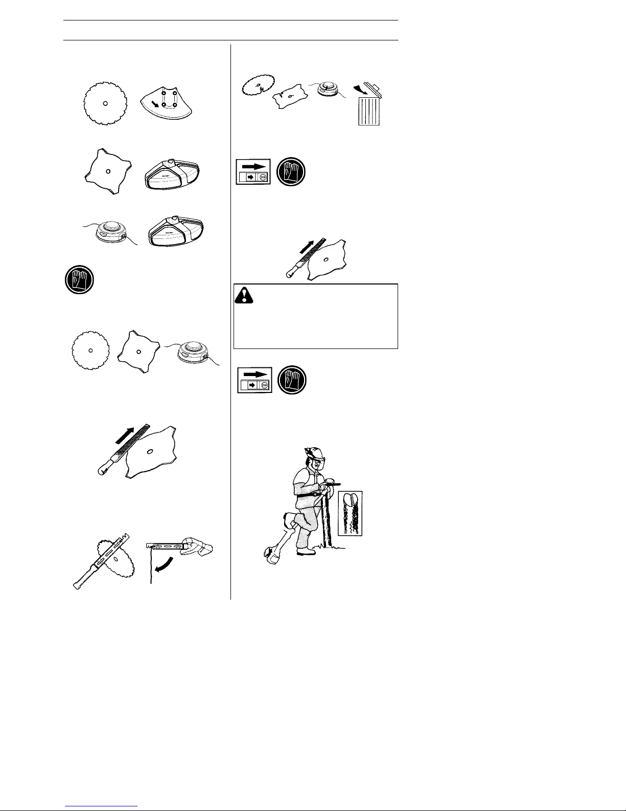
Cutting equipment
This section describes how to choose and
maintain your cutting equipment in order to:
S Redu ce the risk of blade thrust.
S Obtain maximum cutting performance.
S Extend the life of cutting equipment.
Regularly check that the muffler is securely
attached to the machine.
Locking nut
A locking nutis used tosecure some types
of cutting attachment.
WARNING: Always stop the en-
gine before doing any work on the
cutting attachment. This continues
to rotate even after the throttle has
been released. Ensure that the
cutting attachment has stopped
completely and disconnect the
lead from the spark plug before
you start to work on it.
WARNING: Using an incorrect
cutting attachment or an incorrectly sharpened blade increases the
risk of kickback.
WARNING: Mufflers fitted with
catalytic converters get very hot
during use and remain so for some
time after stopping. This also appl ies
at idle speed. Contact can result in
burns to the skin. Remem ber the risk
of fire!
Page 9
E n g l i s h --- 9
115305026 Rev. 3 7/15/10
GENERAL SAFETY PRECAUTIONS
General rules
Only use cutting attachments withthe
guards we recommend! Seethe section on
Technical data.
Keep the teeth of theblade correctly sharpened! Follow our instructions and usethe
recommended file gauge. Anincorrectly
sharpened or damaged bladeincreases the
risk of accidents.
Keep the correct setting on the saw blade!
Follow our instructions and use therecommended setting tool. An incorrectly set saw
blade increases the risk of jammingand
blade thrust, and damageto thesaw blade.
Cutting equipment
Saw blades areintended for cutting fibrous
types of wood.
Grass blades and grass cutters are
intended for cutting coarse grass.
A trimmer head is intended for trimming
grass.
Sharpening grass cutters and
grass blades
S See the cutting attachment packaging for
correct sharpening instructions. Sharpen
blades and cutters using a single--cut flat file.
S Sharpen all edges equally to maintain the
balance of the blade.
Check the cutting attachment
f
or damage
or cracks. A damaged cutting attachment
should always be replaced.
WARNING: Always discard a
blade that is bent, twisted, cracked,
broken or damaged in any other
way. Never attempt to straighten
a twisted blade so that it can be reused. Only use original blades of
the specified type.
Sharpeningthe sawblade
S See the cutting attachment packaging for
correct sharpening instructions.
S A correctly sharpened blade is essential for
working ef ficiently and to avoid unnecessary
wear to the blade and clearing saw .
S Makesure that the blade is wellsupported
when you file it. Use a 5.5 mm round file
with a file holder.
Page 10

E n g l i s h --- 1 0
115305026 Rev. 3 7/15/10
GENERAL SAFETY PRECAUTIONS
S Thefiling angle is 15 degrees. File alter-
nate teeth to the right and those in between to the left. If theblade has been
heavily pitted by stones it may be necessary todress the top edges of the teeth
with a flat file, in exceptional cases. If so,
this should bedone before filing with a
round file. The top edges must be filed
down by the same amount for all the
teeth.
S Adjust theblade setting. This should be
1mm.
Trimmer head
S Only use the recommendedcutting at-
tachments. Seethe section on “T echnical
data”.
IMPORTANT!
Always ensure the trimmer line is wound
tightly and evenly around the drum, otherwise the machine will generate harmful
vibration.
S Smaller machines generally require small
trimmer heads and vice versa. This is because when clearing using trimmer line
the engine must throw out the trimmer
line radially fromthe trimmerhead and
overcome the resistance of the grass
being cleared.
S The length of thetrimmer lineis also im-
portant. A longer trimmer line requires
greater engine power than a shorter
trimmer line of the same diameter.
S Make sure that thecutter on thetrimmer
guard is intact. This is used to cut the
trimmer line to the correct length.
S To increase the lifeof the trimmer line it
can be soaked in water for a couple of
days. This will make the line tougher so
that it lasts longer .
Page 11

E n g l i s h --- 1 1
115305026 Rev. 3 7/15/10
ASSEMBLY
NOTE: Make sureunit is assembled cor-
rectly as shown in this manual.
Fitting the handlebar
S Remove the screw at the rear of the
throttle handle.
S Slidethe throttle handle on tothe right
side of the handlebar(seeillustration).
S Alignthe screw hole in the throttle han-
dle with the hole inthe handlebar.
S Refit the screw in the hole in the rear of
the throttle handle.
S Threadthe screw through the handle
and handlebar. Tighten the screw.
S Position thehandle bar as shown. Fit the
mounting components as shown.
S Put on the harness and hang the machine
from the harness clamp. Now make a final
adjustment so that the machine is in a
comfortable working position when it hangs
from the harness. T ighten the knob.
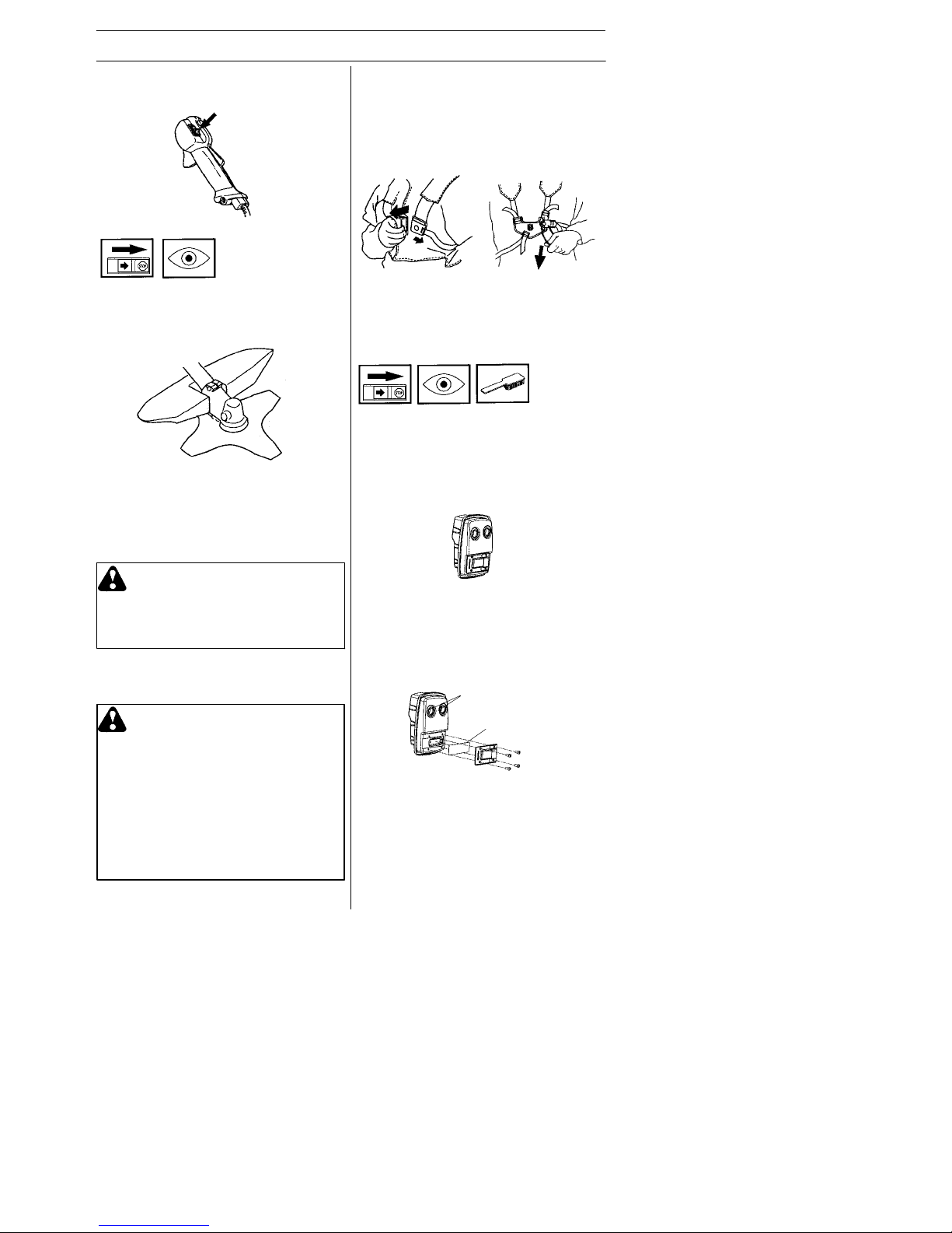
Adjusting the harness
S At the front of the harness is an easily
accessible quick release. Use the quick
release in any emergency situation that
requires you to free yourself from the
machine and harness.
Spreading the load on your
shoulders
S A well--adjusted harness andmachine
makes work much easier.
S Put on the harness. Adjust the harness
for the best working position. Tension the
side straps so that the weight is evenly
distributed across both shoulders.
Fitting the harness
Proper harness and handlebar adjustments must bemade with theengine completely stopped before usingunit.
WARNING: When using a
brushcutter, it must always be
hooked securely to the harness.
Otherwise, you will be unable to
control the brushcutter safely.
This can result in injury to yourself
or others. Never use a harness with
a defective quick release.
Page 12

E n g l i s h --- 1 2
115305026 Rev. 3 7/15/10
ASSEMBLY
Fitting a blade guard, grass
blade and grass cutter
S Hook the blade guard/combination guard
(A) onto the fitting on the shaft and secure
with the bolt.
CAUTION! Use therecommendedblade
guard. See the Technical data section.
S Fitthe drive disc (B) on the output shaft.
S Turn theblade shaft until oneof the
holes in the drive disc aligns with the
corresponding holein the gearhousing.
S Insert the locking pin (C) in the hole to
lock the shaft.
S Place the blade (D), support cup (E) and
support flange (F) on theoutput shaft.
S Fitthe nut (G). The nut must be tight-
ened to a torque of35--50Nm (3.5--5
kpm). Use the socket spanner in thetool
kit. Hold theshaft of the spanner as
close to theblade guard as possible. To
tighten the nut, turn the spanner in the
opposite directionto thedirectionof rotation (CAUTION! left--hand thread).
Fitting blades and trimmer
heads
WARNING: Never use a cutting
attachment without an approved
guard. See the section on Technical data. If an incorrect or faulty
guard is fitted this can cause serious personal injury.
IMPORTANT!
Ifasawbladeorgrassbladeistobeused,
the machine must be equipped with the correct handlebar , blade guard and harness.
Correct balance
Let the cutting attachment rest lightly on the
ground. If you use a saw blade, it should balance about 4 inches (10 cm) above the
ground to prevent contact with stones and
the like. Adj ust the position of the harness
clamp to balance the unit correctly.
Correct height
Adjust the harness so that thecutting attachment is parallel to theground.
WARNING: When fitting the
cutting attachment it is extremely
important that the raised section
on the drive disc/support flang e
engages correctly in the centre hole
of the cutting attachment. If the
cutting attachment is fitted incorrectly it can result in serious and/or fatal
personal injury.
Page 13

E n g l i s h --- 1 3
115305026 Rev. 3 7/15/10
ASSEMBLY
Fitting the blade guard and
saw blade
S Remove the mounting plate (H). Fit the
adapter (I) and bracket (J) with the two
screws (K) as shown. Fit theblade
guard (A) to theadapter using the 4
screws (L) as shown.
CAUTION! Use therecommendedblade
guard. See the Technical data section.
S Fitthe drive disc (B) on the output shaft.
S Turn theblade shaft until oneof the
holes in the drive disc aligns with the
corresponding holein the gearhousing.
S Insert the locking pin (C) in the hole to
lock the shaft.
S Place the blade (D) and support flange
(F) on the output shaft.
S Fitthe nut (G). The nut must betight-
ened to a torque of35--50 Nm (3.5--5
kpm). Use the socket spanner in thetool
kit. Hold theshaft of the spanner as
close to theblade guard as possible. To
tighten the nut, turn the spanner in
the opposite direction tothe direction of
rotation (CAUTION! left--hand thread).
S Whenloosening andtightening the saw
blade nut, there is a risk of injury from the
teeth of the saw blade. You should therefore always ensure that your handis
shielded by theblade guardwhen doing
this. Always use a socket spanner with a
shaft that is long enough toallow this.
The arrow in the diagram shows the area
where you should operate the socket
spanner when loosening or tightening
the nut.
Fitting the trimmer guard and
trimmer head
S Fitthe correct trimmer guard (A) for use
with the trimmer head. Hook the trimmer
guard/combination guard ontothe fitting
on the shaft andsecure withthe bolt (D).
S Fitthe drive disc (B) on the outputshaft.
S Turn theshaft until one of the holes in the
drive disc aligns with the corresponding
hole in the gear housing.
S Insert the locking pin (C) in the hole to
lock the shaft.
S Screw on the trimmer head (H) in the op-
posite directionto thedirectionof rotation.
S To dismantle, follow the instructions in
the reverse order.
A
A
DB
C
H
Page 14

E n g l i s h --- 1 4
115305026 Rev. 3 7/15/10
FUEL HANDLING
Fuel safety
Never start themachine:
1. If you have spilled fuel on it. Wipe off the
spillage and allow remaining fuel to evaporate.
2. If you have spilled fuel on yourself or your
clothes, change your clothes. Wash any
part of your body that has come in contact
with fuel. Use soap and water .
3. If the machine is leaking fuel. Check regularly for leaks from the fuel cap and fuel
lines.
Tr ansport and storage
S Store and transport the machine and fuel
so that thereis norisk of any leakage or
fumes coming into contact with sparks or
naked flames, for example,from electrical machinery, electric motors, electrical
relays/switches or boilers.
S Whenstoringand transporting fuel al-
ways use approved containers intended
for this purpose.
S Whenstoringthe machine for longperi-
ods the fuel tank must be emptied.Contact your local petrol station to findout
where to dispose of excess fuel.
S Ensure the machine is cleaned and that
a complete service is carried out before
long--term storage.
S Thetransportguard must always be
fitted to the cutting attachment whenthe
machine is being transported or in storage.
S Inorder toprevent unintentional starting
of the engine, the spark plug cap must
always be removed during long--term
storage, if themachine is not under
close supervision and when performing
all service measures.
S Secure the machine during transport.
Fuel
CAUTION! The machine is equipped with a
two- -stroke engine and must always be run
using a mixture of petrol and two-stroke
engine oil. It is important to accurately measure the amount of oil to be mixed to ensure
that the correct mixture is obtained. When
mixing small amounts of fuel, even small
inaccuracies can drastically affect the ratio
of the mixture.
Petrol
CAUTION! Always use a good quality pet-
rol/oil mixture (at least 90 octane).
Use low--emission petrol, also known as
alkylate petrol, if itis available.
S The lowest octane recommended is 90.
If you run the engine on a lower octane
than 90, it can result in knocking. This
gives rise to a high engine temperature,
which can result in serious engine damage.
S When working at continuous highrevs, a
higher octane rating is recommended.
Two--stroke oil
S For best results and performance, use
JONSERED two--stroke oil, which is
specially formulatedfor our two--stroke
engines. Mixture 1:50 (2%).
S If JONSERED two- -stroke oil is not avail-
able, you may use another two-stroke oil of
good quality that is intended for air cooled
engines. Contact your dealer when selecting an oil. Mixing ratio 1:33 (3%).
S Never use two--stroke oil intended for
water--cooled outboard engines,
sometimes referredto as outboard oil.
S Never use oil intended for four--stroke
engines.
WARNING: Take care when han-
dling fuel. Bear in mind the risk of
fire, explosion and inhaling fumes.
50,100,15
10 0,20 0,30
15 0,30 0,45
20 0,40 0,60
Petrol,
litre
Two- -stroke oil, litre
2% (1:50) 3% (1:33)
WARNING: Fuel and fuel fumes
are highly inflammable and can
cause serious injury when inhaled
or allowed to come in contact with
the skin. For this reason observe
caution when handling fuel and
make sure there is adequate ventilation.
Page 15

E n g l i s h --- 1 5
115305026 Rev. 3 7/15/10
FUEL HANDLING
S Always start by filling half the amount of
the petrol to be used. Then add the entire
amount of oil. Mix (shake) the fuel mixture.
Add the remaining amount of petrol.
S Mix (shake) the fuel mixture thoroughly
before filling the machine’s fuel tank.
S Donot mix more than one month’s sup-
ply of fuel ata time.
S If the machine is not used for some time,
the fuel tank should be emptied and
cleaned.
WARNING: The catalytic con-
verter muffler gets very hot during
and after use. This also applies
during idling. Be aware of thefire
hazard, especially when working
near flammable substances and/or
vapors.
Fueling
WARNING: Taking the following
precautions, will lessen the risk of
fire:
Do not smoke or place hot objects
near fuel.
Always shut off the engine before
refueling.
Always stop the engine and let it
cool for a few minutes before refuelling.
When refueling, open the fuel cap
slowly so that any excesspressure
is released gently.
Tighten the fuel cap carefully after
refueling.
Always move the machine away
from the refueling area before
starting.
Min. 3 metres
Mix
i
ng
S Always mix the petroland oil ina clean
container intended for fuel.
S Cleanthe areaaround thefuel cap.
Contamination in the tank can cause
operating problems.
S Ensure that the fuel is well mixed by shak-
ing the container before filling the tank.
Page 16

E n g l i s h --- 1 6
115305026 Rev. 3 7/15/10
STARTING AND STOPPING
Check before starting
S Check the blade to ensure that no cracks
have formed at the bottom of the teeth or
by the centre hole. The most common reason why cracks are formed is that sharp
corners have been formed at the bottom of
the teeth while sharpening or that the blade
has been used with dull teeth. Discard a
blade if cracks are found.
S Check that the support flange is not
cracked due to fatigue or due to being
tightened too much. Discard the support
flange if it is cracked.
S Ensure the locking nut has not lost its cap-
tive force. The nut lock should have a
locking force of at least 1.5 Nm. The tightening torque of the locking nut should be
35--50 Nm.
S Check that the trimmer headand trimm er
guard are not damaged or cracked.
Replace the trimmer head or trimmer
guard if they have been exposed to
impact or are cracked.
S Never use the machine without a guard
nor with a defective guard.
S All covers must be correctly fitted and un-
damaged before you start the machine.
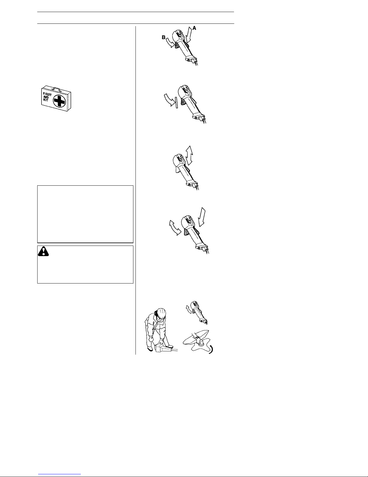
Cold engine
Primer bulb: Press the primer bulb 10
times until fuel begins to fillthe bulb. The
primer bulb need not becompletely filled.
Choke: Move theblue engine choke lever
over to the closed position.
Starting
Hold the body of the machine on the
ground using your left hand (CAUTION!
Not with your foot!).
Firmly grip thestarter ropehandle with
your right hand.DO NOT squeeze
throttle trigger.Slowly pull out thecord
until you feel some resistance (the starter
pawls grip); then quickly and powerfully
pull the cord.
Never wrap the starter cord around
your hand.
Repeat pulling the cord untilthe engine
attempts to start. Move the blue engine
choke lever to the½ position. Pull starter
rope until engine runs. Move the blue
engine choke lever tothe opened position.
WARNING: The complete clutch,
clutch cover , and shaft must be
fitted before the machine is started,
otherwise parts could com e loose
and cause personal injury .
Always move the machine away
from the refueling area before
starting. Place the machine on a
flat surface. Ensure the cutting attachment cannot come into contact
with any object.
Make sure no unauthorized
persons are in the working area,
otherwise there is a risk of serious
personal injury. The safety
distance is 15 metres.
Starting and stopping
Page 17

E n g l i s h --- 1 7
115305026 Rev. 3 7/15/10
STARTING AND STOPPING
Warmengine
With a warm engine, move theblue engine
choke lever to the½ position. Pull starter
rope until engine runs. Movethe blue
engine choke lever tothe opened position.
CAUTION!
Do not put any part of your body in marked
area. Contact can result in burns to the
skin, or electrical shock if the spark plug
cap has beendamaged. Always use
gloves. Donot use a machine withdamaged spark plugcap.
CAUTION! Do not pull the starter cord all
the way out and do not let go ofthe starter
handle when the cord is fully extended.
This can damagethe machine.
NOTE: If engine dies, return blue engine
choke lever to theclosed position and
repeat starting steps.
For throttle handles with a start
throttle lock--out:
Set the throttle tothe start position by first
pressing the throttle lock--out and the
throttle trigger, then pressing thestart
throttle button (A). Then release the throttle
lock--out and the throttle trigger, followed
by the start throttle button. Thethrottle
function is now activated. To return the engine to idle, press the throttle lock--out and
throttle trigger again.
Stopping
Stop the engine by pushing and holding
the stop switch in the STOP position until
the engine stops.
CAUTION! The stop switch automatically
returns to thestart position. In order to prevent unintentional starting, the spark plug
cap must be removed from the spark plug
when assembling, checking and/or performing maintenance.
WARNING: When the engine is
started with the choke in the closed
position the cutting attachment will
start to rotate immediately.
Page 18

E n g l i s h --- 1 8
115305026 Rev. 3 7/15/10
WORKING TECHNIQUES
General working instructions
IMPORTANT!
This section describes the basic safety precautions for working with trimmers. If you
encounter a situation where you are uncertain how to proceed you should ask an expert. Contact your servicing dealer.
Avoid all usage which you consider to be
beyond your capability.
You must understand the difference between
forestry clearing, grass clearing and grass
trimming before use.
Basic safety rules
1. Look around you:
S To ensure that people, animals or other
things cannot affect your control of the
machine.
S To ensure that people, animals, etc.,
do not come into contact with the cutting attachment or loose objects that
are thrown out by the cutting attachment.
S CAUTION!Do not use themachine
unless youare ableto call for helpin
the event of anaccident.
2. Inspect the working area. Remove all
loose objects, such as stones, broken
glass, nails, steel wire, string, etc. that
could be thrown out or become wrapped
around the cutting attachment.
3. Do not use the machine in bad weather ,
such as dense fog, heavy rain, strong
wind, intense cold, etc. Working in bad
weather is tiring and often brings added
risks, such as icy ground, unpredictable
felling direction, etc.
4. Make sure you can move and stand safely. Check the area around you for possible
obstacles (roots, rocks, branches, ditches,
etc.) in case you have to move suddenly.
T ake great care when working on sloping
ground.
5. T ake great care when cutting a tree that is
in tension. A tree that is in tension may
spring back to its normal position before or
after being cut. If you position yourself
incorrectly or m ake the cut in the wrong
place the tree may hit you or the machine
and cause you to lose control. Both
situations can cause serious personal injury .
6. Keep a good balance and a firm foothold.
7. Always hold the machine with both hands.
Hold the machine on the right side of your
body.
8. Keep the cutting attachment below waist
level.
9. Switch off the engine before moving to
another area. Fit the transport guard before
carrying or transporting the equipment any
distance.
10.Never put the machine down with the engine running or while the cutting attachment
is rotating.
WARNING: Neither the operator
of the machine nor anyone else
may attempt to remove the cut material while the engine is running or
the cutting equipment is rotating,
as this can result in serious injury.
Stop the engine and cutting equipment before you remove material
that has wound around the blade
shaft as otherwise there is a risk of
injury. The bevel gear can get hot
during use and may remain so for a
while afterwards. You could get
burned if you touch it.
The ABC of clearing
S Always use the correct equipment.
S Make sure the equipment is well adju sted.
S Follow the safety precautions.
S Organize your work carefully.
S Always use full throttle when starting to cut
with the blade.
S Always use sharp blades.
S Avoid stones.
S Control the fellingdirection (take advan-
tage of the wind).
Page 19

E n g l i s h --- 1 9
115305026 Rev. 3 7/15/10
WORKING TECHNIQUES
WARNING: Sometimes branches
or grass get caught between the
guard and cutting attachment.
Always stop the engine before
cleaning.
WARNING: Watch out for
thrown objects. Always wear approved eye protection. Never lean
over the cutting attachment guard.
Stones, rubbish, etc. can be thrown
up into the eyes causing blindness
or serious injury. Keep unauthorised persons at a distance. Children, animals, onlookers and helpers should be kept outside the
safety zone of 50 feet (15 meters).
Stop the machine immediately if
anyone approaches. Never swing
the machine around without first
checking behind you to make sure
noone is within the safety zone.
Working methods
WARNING: Machines fitted with
saw blades or grass blades can be
thrown violently to the side when
the blade comes into contact with a
fixed object. This is called blade
thrust. A blade thrust can be violent
enough to cause the machine and/
or operator to be propelled in any
direction, and possibly lose control
of the machine. Blade thrust can
occur without warning if the machine snags, stalls or binds. Blade
thrust is more likely to occur in
areas where it is difficult to see the
material being cut.
Avoid cutting with the area of the
blade between the 12 o’clock and 3
o’clock positions. Because of the
speed of rotation of the blade kickback can occur if you attempt to
cut thick stems with this area of the
blade.
Basic working techniques
S Always slow the engineto idle speed after
each working operation. Longperiods at
full throttle without any load on theengine
can lead to serious engine damage.
S Work systematically to and fro across the
area, clearing a width of around 12--15 feet
(4- -5 meters) on each pass. This exploits
the full reach of the machine in both directions and gives the operator a convenient
and varied working area to work in.
S Clear a strip around 250 feet (75 meters)
long. Move your fuel can as work progresses.
S On sloping ground you should work along
the slope. It is much easier to work along a
slope than it is to work up and down it.
S You should plan the strip so that you avoid
going over ditches or other obstacles on
the ground. Y ou should also orient the strip
to take advantage of wind conditions, so
that cleared stems fall in the cleared area
of the stand.
S Before you start clearing, check the clear-
ing area, the type of terrain, the slope of
the ground, whether there are stones, hollows etc.
S Start at whichever end of the area is easi-
est, and clear an open space from which
to work.
Forestry clearing using a saw blade
S Therisk of blade thrust increases with in-
creasing stem size. Y oushould therefore
avoid cutting with the area of theblade between 12 o’clock and 3 o’clock.
Page 20

E n g l i s h --- 2 0
115305026 Rev. 3 7/15/10
WORKING TECHNIQUES
S Tofell to the left, the bottom ofthe tree
should be pushed to the right. Tilt the
blade and bring it diagonally downto
the right, exerting firmpressure. At the
same time pushthe stem usingthe blade
guard. Cut withthe area of the blade between 3 o’clock and 5 o’clock. Apply full
throttle before advancing the blade.
S To fellto the right, the bottom of thetree
should be pushed to the left. Tilt the blade
and bring it diagonally up to theright. Cut
with the area ofthe blade between 3
o’clock and5 o’clock so that thedirection
of rotation of theblade pushes thebottom
of the tree to the left.
S To fella treeforwards, the bottom of the
tree should be pulledbackwards. Pull the
blade backwards with a quick, firm movement.
S Largestems must be cut from two sides.
First determine which direction the stem
will fall. Make the first cut on thefelling
side. Then finish cutting the stem fromthe
other side. Adjust the cutting pressure to
match the size of the stem and thehardness of thewood. Smallstems require
more pressure, while large stems require
less pressure.
S Ifthe stems are tightly packed, adapt your
walking pace to suit.
S Ifthe blade jams in astem, never jerk the
machine free. If you do this the blade,
bevel gear, shaft or handlebar may be
damaged. Release the handles, grip the
shaft with bothhands andgently pull the
machine free.
Brush cutting with a saw blade
S Thinstems and brush aremown down.
Work with a sawing movement, swinging
sideways.
S Try to cut several stems in a single sawing
movement.
S Withgroups of hardwoodstems, first clear
around the group. Start by cutting the
stems high uparound the outside of the
group to avoid jamming.Then cut the
stems to therequired height. Now try to
reach in with the blade andcut from the
center of thegroup. Ifit is still difficult to
gain access, cut the stems high upand let
them fall. This will reduce the risk of jamming.
Page 21

E n g l i s h --- 2 1
115305026 Rev. 3 7/15/10
WORKING TECHNIQUES
Grass trimming wit h a tr i mmer head
Trimming
S Hold the trimmer head just above the ground
at an angle. It is the end of the trimmer line
that does the work. Let the trimmer line work
at its own pace. Never press the trimmer
lineintotheareatobecut.
S The trimmer line can easily remove grass
and weeds up against walls, fences, trees
and borders, however it can alsodamage
sensitive bark on trees and bushes, and
damage fence posts.
S Reduce the risk of damaging plants by
shortening the trimmer line to 10--12 cm
and reducing the engine speed.
S When trimming you should use less than
full throttle sothat the trimmer line lasts
longer and to reduce the wear on the
trimmer head.
Grass clearing usi ng a gr ass blade
S Grass blades and grass cutters must not be
used on woody stems.
S A grass blade is used for all types of tall or
coarse grass.
S Thegrassiscutdownwithasideways,
swinging movement, where the movement
from right--to--left is the clearing stroke and
the movement from left--to--right is the return
stroke. Let the left--hand side of the blade
(between 8 and 12 o’clock) do the cutting.
S If the blade is angled to the left when clear-
ing grass, the grass will collect in a line,
which makes it easier to collect, e.g. by
raking.
S Trytoworkrhythmically.Standfirmlywith
your feet apart. M ove forward after the return stroke and stand firmly again.
S Let the support cup rest lightly against the
ground. It is used to protect the blade from
hitting the ground.
S Reduce the risk of material wrapping
around the blade by following these instructions:
S Always work at full throttle.
S Avoid the previously cut material during
the return stroke.
S Stop the engine, unclip the harness and
place the machine on the ground before
you star tto collectthe cut
material.
Clearing
S Theclearing technique removes all un-
wanted vegetation. Keep the trimmer
head just abovethe ground and tilt it. Let
the end of the trimmer line strike the
ground around trees, posts, statues and
the like. CAUTION! This technique
increases the wear on thetrimmer line.
S Thetrimmer linewears quicker and must
be fed forward moreoften whenworking
against stones, brick, concrete, metal
fences, etc., thanwhen coming into contact with trees and wooden fences.
Cutting
S Thetrimmer is ideal for cuttinggrass that
is difficult to reach using a normal lawn
mower. Keep the trimmer line parallelto
the ground when cutting. Avoid pressing
the trimmer head against the ground as
this can ruin the lawn and damagethe
tool.
Page 22

E n g l i s h --- 2 2
115305026 Rev. 3 7/15/10
WORKING TECHNIQUES
S Donot allow the trimmerhead to con--
stantly come into contact with the ground
during normal cutting.Constant contact
of this type can cause damage andwear
to the trimmer head.
Sweeping
S Thefan effect ofthe rotating line can be
used for quick and easy clearing up.
Hold the trimmer lineparallel toand
above the area tobe swept and move
the tool to and fro.
S Whencutting and sweeping youshould
use full throttle to obtain the bestresults.
WARNING: Neither the operator
of the machine nor anyone else may
attempt to remove the cut material
while the en gine is running or the
trimmer line is rotating, as this can
result in serious injury. Stop the
engine and trimmer head before you
remove material that has wound
around the drive shaft as otherwise
there is a risk of injury. The bevel
gear can get hot during use and may
remain so for a while afterwards. You
could get burned if you touch it.
WARNING: Watch out for thrown
objects. Always wear eye protection.
Never lean over the cutting attachment guard. Stones, rubbish, etc.
canbethrownupintotheeyes
causing blindness or serious injury.
Keep unauthorized persons at a distance. Children, animals, onlookers
and helpers should be kept outside
thesafetyzoneof 15metres. Stop
the machine immediately if anyone
approaches.
Page 23

E n g l i s h --- 2 3
115305026 Rev. 3 7/15/10
MAINTENANCE
Idle Speed
Screw--T
Adjusting the st ar t throttle speed
The correct start throttle speedis set by
means of an adjuster on the rear of the
handle next to thecable. Use this screw (4
mm Allen screw) to increase ordecrease
the start throttle speed.
Proceed as follows:
1. Run the machine at idle.
2. Press the start throttle lock as described
under the heading Starting and stopping.
3. If the start throttle speed is too low (below
4000 rpm), turn adjuster screw (A) clockwise until the cutting attachment starts to
rotate. Then turn adjuster screw (A)
clockwise an additional 1/2 turn.
4. If the start throttle speed is too high, turn
adjuster screw (A) counterclockwise
until the cutting attachment stops. Then
turn adjuster screw (A) clockwise an
additional 1/2 turn.
Carburetor
Y our Jonsered product has been designed
and manufactured to specifications that reduce harmful emissions. After the engine
has used 8--10 tanks of fuel, the engine will
be run--in. To ensure that it continues to run
at peak performance and tominimize harmful exhaust emissions after the run--inperiod, ask your servicing dealer to adjust your
carburetor.
The li
f
e span ofthe machine can be reduced
and the risk of accidents can increase if
machine maintenance is not carried out
correctly and if service and/or repairs are not
carried out professionally . If you need further
information, please contact your nearest
authorised service dealer .
WARNING: The complete clutch,
clutch cover, and shaft mu st be
fitted before the machine is started,
otherwise parts could come loose
and cause personal injury.
Function
S Thecarburetor governs the engine’s
speed via thethrottle control. Air and fuel
are mixed in thecarburetor.
S TheT--screw regulates thethrottle setting
at idle speed. Ifthe T--screw is turned
clockwise this gives a higher idlespeed;
turning it counterclockwise gives a lower
idle speed.
Basic setting
S Thebasic carburetor settings are ad-
justed during testing at the factory.Fine
adjustment should becarried out by a
skilled technician.
Rec. idle speed:
See “T echnical data” section.
Recommended max. speed:
See “T echnical data” section.
CAUTION! If the cutting attachmentrotates
when the engine is idling the idleadjustment
screw Tshould beturned counterclockwise
until the cutting attachment stops.
WARNING: If the idle speed can-
not be adjusted so that the cutting
attachment stops, contact your
servicing dealer . Do not use the
machine until it has been correctly
adjusted or repaired.
Fine adjustment of the idle speed--T
Adjust the idle speed using the idleadjustment screw--T if itis necessary to readjust.
First, turn theidle adjustment screw--T
clockwise untilthe cutting attachment starts
to rotate. Then, turnthe screw counterclockwise untilthe cutting attachment stops.
The idle speed is correctly adjusted when
the engine will run smoothly in every position. The idle speedshould also be well
below the speed at which the cutting attachment starts to rotate.
4mm
Page 24

E n g l i s h --- 2 4
115305026 Rev. 3 7/15/10
MAINTENANCE
If the mesh is frequently blocked, this can
be a sign that the performance of thecatalytic converter is impaired. Contact your
servicing dealer to inspect the muffler. A
blocked meshwill cause the machine to
overheat and result in damageto the cylinder and piston.
Muffler bolts
CAUTION! Never use a machine that has
a faulty or loose muffler. Ensure themuffler
bolts are tight.
Spark arrestor mesh
WARNING: Mufflers fitted with
catalytic converters get very hot
during use and remain so for some
time after stopping. This also applies at idle speed . Contact can result in burns to the skin. Remember
theriskoffire!
WARNING: Theinsideofthe
muffler contain chemicals that may
be carcinogenic. Avoid contact with
these elements in the event of a
damaged muffler .
WARNING: Bear in mind that:
Engine exhaust fumes contain carbon monoxide, which can cause
carbon monoxide poisoning. For
this reason you should not start or
run the ma chine indoors, or anywhere that is poorly ventilated.
The exhaust fumes from the engine
are hot and may conta in sparks
which can start a fire. Never start
the machine indoors or near combustible material!
Spark plug
The spark plug condition is influenced by:
S Incorrect carburetor adjustment.
S Anincorrect fuel mixture (too much or in-
correct type of oil).
S A dirty air filter.
These factors cause deposits on the spark
plug electrodes, which may result in operating problems and starting difficulties.
If the machine is low on power, difficult to
start or runs poorly at idle speed: always
check thespark plug first before taking
any further action.
If the spark plug is dirty, clean it andcheck
that the electrodegap is 0.024 inch (0.6
mm). The spark plug should be replaced
after about a month inoperation or earlier if
necessary.
0.024 inch (0.6 mm)
CAUTION! Always use the recommended
spark plug type! Use of the wrong spark
plug can damage the piston/cylinder.
Muffler
CAUTION! Muffler is fitted with a catalytic
converter designed to reduce harmful exhaust gases.
The muffler is designedto reduce the noise
level and to direct the exhaust gases away
from the operator. The exhaust gases are
hot and can contain sparks, which may
cause fire ifdirected against dry and combustible material.
Mufflers are equipped witha special spark
arrestor mesh. The mesh should be
checked and,if necessary. cleaned by a
servicing dealer. If the mesh is damaged,
it should be replaced.
Unit/Maintenance Safety
Disconnect the spark plug before performing maintenance, except carburetor adjustments.
Page 25

E n g l i s h --- 2 5
115305026 Rev. 3 7/15/10
MAINTENANCE
Bevel gear
The bevel gear is filled with the right quantity of grease at the factory.However, before using the machine you shouldcheck
that the bevel gearis filled three--quarters
full with grease. Use JONSRED special
grease.
The grease in the bevelgear does not normally need to be changed except if repairs
are carried out.
Air filter
The air filter must be regularly cleaned to
remove dust and dirt inorder toavoid:
S Carburetor malfunctions
S Starting problems
S Loss of engine power
S Unnecessary wear to engineparts
S Excessive fuelconsumption
Clean the filter every 25 hours, or more
regularly if conditions are exceptionally
dusty.
Cleaning the air filter
Remove the air filter cover and takeout the
filter. Wash it clean in warm, soapy water.
Rinse thoroughly. Ensure that the filter is dry
before refitting it.
An air filter that has been in use for a long
time cannot be cleaned completely .The
filter must therefore be replaced with a new
one at regular intervals. A damaged air
filter must always be replaced.
Page 26

E n g l i s h --- 2 6
115305026 Rev. 3 7/15/10
MAINTENANCE
Maintenance
Daily
Maintenance
Weekly
Maintenance
Monthly
Maintenance
Maintenance schedule
The following is a list of themaintenance thatmust beperformed onthe machine. Most of
the items are described in the Maintenance section. The user must only carry out the maintenance and service work described in this Operator’s Manual. More extensive work must
be carried out by an authorised service workshop.
Clean the outside of the machine.
Make sure thethrottle trigger lock and the
throttle function correctly from a safety point
of view.
Check that the stop switch works correctly.
Check that the cutting attachment does not
rotate at idle.
Clean the air filter. Replaceif necessary.
Check that the cutting attachment guard is
undamaged and not cracked. Replace the
cutting attachment guard if ithas been
exposed to impact or is cracked.
Check that the trimmerhead is undamaged
and not cracked. Replace the trimmerhead
if necessary.
Check that the locking nut of the cutting
equipment is tightened correctly.
Check that nuts and screws are tight.
Check that there areno fuel leaks from the
engine, tank or fuellines.
Check thestarter and starter cord.
Clean the outside of the spark plug. Re-
move it and check the electrode gap. Adjust
the gap to 0,6 mm orreplacethe spark plug.
Check that the spark plug is fitted with a
suppressor.
Clean the outside of the carburetor and the
space around it.
Check that the bevel gear is filled three-quarters full with lubricant. Fill ifnecessary
using specialgrease.
Check the fuel filter from contamination and
the fuel hose fromcracks or other defects.
Replace if necessary.
Check all cables and connections.
Check the clutch, clutch springs and the
clutch drum for wear. Replaceif necessary
by an autorized service workshop.
Replace the spark plug. Check that the
spark plug is fitted with asuppressor.
Clean or replacethe spark arrestor mesh
on the muffler.
X
X
X
X
X
X
X
X
X
X
X
X
X
X
X
X
X
X
X
Page 27

E n g l i s h --- 2 7
115305026 Rev. 3 7/15/10
TECHNICAL DATA
Model CC 2128 (M10LH arbor shaft thread) -- Centre hole in blades/cutters, ∅ 25,4 mm
Approved accessories Type Cutt ing attachment / guard, part. no.
Grass blade/grass cutter Grass 255--4 1 inch 504 00 13--03 /545 08 18--79
(∅ 250 4--teeth)
Saw blade Scarlet 200--22 1 inch 537 27 75--04 / 537 21 71--01
(∅ 200 22--teeth)
Trimmer head T25(∅ 2,4 -- 2,7 mm lin e) 537 33 83--06/ 545 0818--79
Plastic blades Tricut 300 mm (separate 531 00 38--11 / 545 08 18--79
blades have part number
531 00 77--15)
Support cup Fixed --
Technical data
CC 2128
Engine
Cylinder displacement, cm
3
28
Cylinder bore, mm 35
Stroke, mm 28,7
Idle speed, rpm 2800--3200
Recommended max. fast idle speed, rpm 11000
Speed of output shaft, rpm 8000
Max. engine output, according to ISO 8893,kW 0,8
Catalytic converter muffler Y es
Speed--regulated ignition system Yes
Ignition system
Spark plug Champion RCJ--8Y
Electrode gap, mm 0,6
Fuel and lubrication system
Fuel tank capacity,liter 0,4
Weight
Weight without fuel, cutting attachment and guard, kg 4,8
Noise emissions
(see note 1)
Sound power level, measured dB(A) 109
Sound power level, guaranteed L
WA
dB(A) 114
Noise levels
(see note 2)
Equivalent sound pressure level at theoperators’ ear,
measured according to EN/ISO 11806 and ISO 22868, dB(A)
Equipped with saw blade (original) 100
Equipped with grass blade (original) 100
Equipped with trimmer head(original) 100
Vibration levels
(see Note 3)
Equivalent vibration levels (a
hv,eq
) at handles, measured
according to EN ISO 11806 and ISO 22867, m/s
2
Equipped with saw blade (original), left/right 3,2/4,4
Equipped with grass blade (original), left/right 3,8/3,8
Equipped with trimmer head(original),left/right 3,7/4,4
Note 1: Noise emissions in the environmentmeasuredas sound power (L
WA
) in conformity with EC directive 2000/14/EC. Reported sound power level for the machinehas been
measured with the original cutting attachment that gives the highest level. The dif ference
between guaranteed and measured sound power is that the guaranteed sound power also
includes dispersion in the measurement result and the variations between different machines of thesamemodel according to Directive2000/14/EC.
Note 2: Reported data for equivalent sound pressure level for the machine has a typical
statisticaldispersion (standard deviation) of 1 dB(A).
Note 3: Reported data for equivalent vibration level has a typical statistical dispersion
(standard deviation) of 1m/s
2
.
Page 28

E n g l i s h --- 2 8
115305026 Rev. 3 7/15/10
DECLARATION OF CONFORMITY
EC Declaration of Conformity (Only applies to Europe)
We, Husqvarna AB, SE-561 82 Huskvarna, Sweden, tel: +46--36--146500, as authorised
representative inthe Community,declare thatthe brushcutter modelJonsered CC 2128with
serial numbers dating from 2009and onwards(the yearis clearly stated on the rating plate,
followed by the serial number), comply with the requirements of the COUNCIL’S
DIRECTIVES:
of 17 May 2006 “relating tomachinery” 2006/42/EC;
of15 December2004“relatingto electromagnetic compatibility”2004/108/EC, and applicable
supplements; and
of 8 May 2000“relating to the noise emissionsin the environment” in accordance with Annex
Vof2000/14/EC. For information relatingto noise emissions, see Technical data section.
The following standards have been applied: EN ISO 12100--1/A1:2009, EN ISO
12100--2/A1:2009, CISPR 12:2007, EN 11806:2008.
SMP, The Swedish Machinery Testing Institute, Fyrisborgsgatan 3 S--754 50 Uppsala,
Sweden, has performed voluntary type examination on behalf of Husqvarna AB. The
certificate(s) are numbered: SEC/09/2046.
09 -- 11 -- 0 1
Ronnie E. Goldman,Director of Engineering
Authorized representative for Husqvarna AB and
responsible for technical documentation
Page 29

E n g l i s h --- 2 9
115305026 Rev. 3 7/15/10
Trimmer Head Line Loading Instructions
20i
10i
3m
6m
1
23
45
6
78
9
Page 30

E n g l i s h --- 3 0
115305026 Rev. 3 7/15/10
Plastic Blades (Tri Cut)
12
3
4
5
6
7
8
 Loading...