

Page 1

POWERTECH E 4.5 &
Doosan purchased Bobcat Company from Ingersoll-Rand Company in
2007. Any reference to Ingersoll-Rand Company or use of trademarks,
service marks, logos, or other proprietary identifying marks belonging
to Ingersoll-Rand Company in this manual is his torical or nominative
in nature, and is not meant to suggest a current affiliation between
Ingersoll-Rand C
ompany and Doosan
Company or the products of
e
ith
er.
6.8L Diesel Engines
Level 16 Electronic
Fuel System With
Denso HPCR
TECHNICAL MANUAL
POWERTECH E 4.5 & 6.8 L Diesel
Engines—Level 16 Electronic Fuel
System with Denso HPCR
CTM502 31MAY07 (ENGLISH)
For complete service information also see:
POWERTECH 4.5 L and 6.8 L Diesel
Engines—Base Engine ................. CTM104
Alternators and Starter Motors ........... CTM77
OEM Engine Accessories ...... CTM67 (English Only)
John Deere Power Systems
LITHO IN U.S.A.
Page 2
Foreword
Introduction
This manual is written for an experienced technician.
Essential tools required in performing certain service
work are identified in this manual and are
recommended for use.
This manual (CTM502) covers only Level 16 Electronic
Fuel System with the Denso High Pressure Common
Rail (HPCR) and 2-valves per cylinder for PowerTech
“E” engines. It is one of seven volumes on 4.5 L and
6.8 L engines. The following companion manual covers
the base engine.
• CTM104—Base Engine
Live with safety: Read the safety messages in the
introduction of this manual and the cautions presented
throughout the text of the manual.
This is the safety-alert symbol. When you see this
symbol on the machine or in this manual, be alert to
the potential for personal injury.
Use this component technical manual in conjunction
with the machine technical manual. An application
listing in Section 01, Group 001 identifies
product-model/component type-model relationship. See
the machine technical manual for information on
component removal and installation, and gaining
access to the components.
Information is organized in sections and groups for the
various components requiring service instruction. At
the beginning of each group are summaries of the up
coming group.
Before beginning repair on an engine, clean the
engine.
This manual contains SI Metric units of measure
followed immediately by the U.S. customary units of
measure. Most hardware on these engines are metric
sized.
Some components of this engine may be serviced
without removing the engine from the machine. Refer
to the specific machine technical manual for
information on components that can be serviced
without removing the engine from the machine and for
engine removal and installation procedures.
Read each block of material completely before
performing service to check for differences in
procedures or specifications.
CALIFORNIA PROPOSITION 65 WARNING: Diesel
engine exhaust and some of its constituents are
known to the State of California to cause cancer,
birth defects, and other reproductive harm.
CD03523,000016D –19–30MAY07–1/1
CTM502 (31MAY07) 4.5 & 6.8 L Level 16 Electronic Fuel System
060407
PN=2
Page 3

SECTION 01—General
Group 000—Safety
Group 001—Engine Identification
Group 002—Fuels, Lubricants, and Coolant
Contents
01
SECTION 02—Repair and Adjustments
Group 090—Electronic Fuel System Repair and
Adjustments
Group 110—Electronic Engine Control Repair and
Adjustment
SECTION 03—Theory Of Operation
Group 130—Electronic Fuel System Operation
Group 135—Air and Exhaust Operation
Group 140—Electronic Control System Operation
SECTION 04—Diagnostics
Group 150—Observable Diagnostics and Tests
Group 160—Trouble Code Diagnostics and Tests
SECTION 05—Tools
Group 170—Electronic Fuel/Control System Repair
Tools and Other Material
Group 180—Diagnostic Service Tools
SECTION 06—Specifications
Group 200—Repair Specifications
Group 210—Diagnostic Specifications
02
03
04
05
06
All information, illustrations and specifications in this manual are based on
the latest information available at the time of publication. The right is
reserved to make changes at any time without notice.
COPYRIGHT2006
DEERE & COMPANY
Moline, Illinois
A John Deere ILLUSTRUCTIONManual
CTM502 (31MAY07) i 4.5 & 6.8 L Level 16 Electronic Fuel System
All rights reserved
060407
PN=1
INDX
Page 4

01
02
03
04
05
Contents
06
INDX
CTM502 (31MAY07) ii 4.5 & 6.8 L Level 16 Electronic Fuel System
060407
PN=2
Page 5

Page
Group 000—Safety ....................01-000-1
Group 001—Engine Identification
Engine Serial Number Plate Information .....01-001-1
OEM Engine Option Code Label ...........01-001-3
Information Relative to Emissions
Regulations .........................01-001-3
Emissions Control System Certification
Label ..............................01-001-4
Engine Application Charts ................01-001-5
Group 002—Fuels, Lubricants, and Coolant
Diesel Fuel ...........................01-002-1
Bio-Diesel Fuel ........................01-002-2
Minimizing the Effect of Cold Weather on
Diesel Engines.......................01-002-3
Handling and Storing Diesel Fuel ..........01-002-4
Lubricity of Diesel Fuel ..................01-002-5
Testing Diesel Fuel .....................01-002-5
Engine Oil and Filter Service Intervals.......01-002-5
Diesel Engine Oil ......................01-002-6
Diesel Engine Break-In Oil ...............01-002-7
Oil Filters.............................01-002-7
Alternative and Synthetic Lubricants ........01-002-8
Lubricant Storage ......................01-002-8
Mixing of Lubricants ....................01-002-8
Grease ..............................01-002-9
Diesel Engine Coolant..................01-002-10
Supplemental Coolant Additives ..........01-002-11
Operating in Warm Temperature Climates . .01-002-12
Additional Information About Diesel
Engine Coolants and Supplemental Coolant
Additives ..........................01-002-13
Testing Diesel Engine Coolant ...........01-002-14
Drain Intervals for Diesel Engine Coolant . . .01-002-15
01
Section 01
General
Contents
CTM502 (31MAY07) 01-1 4.5 & 6.8 L Level 16 Electronic Fuel System
060407
PN=1
Page 6

01
Contents
CTM502 (31MAY07) 01-2 4.5 & 6.8 L Level 16 Electronic Fuel System
060407
PN=2
Page 7
Work In Ventilated Area
Engine exhaust fumes can cause sickness or death. If it is
necessary to run an engine in an enclosed area, remove
the exhaust fumes from the area with an exhaust pipe
extension.
If you do not have an exhaust pipe extension, open the
doors and get outside air into the area
Group 000
Safety
01
000
1
Recognize Safety Information
This is a safety-alert symbol. When you see this symbol
on your machine or in this manual, be alert to the
potential for personal injury.
Follow recommended precautions and safe operating
practices.
Work in Clean Area
Before starting a job:
• Clean work area and machine.
• Make sure you have all necessary tools to do your job.
• Have the right parts on hand.
• Read all instructions thoroughly; do not attempt
shortcuts.
DX,AIR –19–17FEB99–1/1
TS220 –UN–23AUG88
T81389 –UN–07DEC88
DX,ALERT –19–29SEP98–1/1
CTM502 (31MAY07) 01-000-1 4.5 & 6.8 L Level 16 Electronic Fuel System
DX,CLEAN –19–04JUN90–1/1
T6642EJ –UN–18OCT88
060407
PN=7
Page 8
01
000
Dispose of Waste Properly
2
Improperly disposing of waste can threaten the
environment and ecology. Potentially harmful waste used
with John Deere equipment include such items as oil, fuel,
coolant, brake fluid, filters, and batteries.
Use leakproof containers when draining fluids. Do not use
food or beverage containers that may mislead someone
into drinking from them.
Safety
Do not pour waste onto the ground, down a drain, or into
any water source.
Air conditioning refrigerants escaping into the air can
damage the Earth’s atmosphere. Government regulations
may require a certified air conditioning service center to
recover and recycle used air conditioning refrigerants.
Inquire on the proper way to recycle or dispose of waste
from your local environmental or recycling center, or from
your John Deere dealer.
Avoid Harmful Asbestos Dust
Avoid breathing dust that may be generated when
handling components containing asbestos fibers. Inhaled
asbestos fibers may cause lung cancer.
Components in products that may contain asbestos fibers
are brake pads, brake band and lining assemblies, clutch
plates, and some gaskets. The asbestos used in these
components is usually found in a resin or sealed in some
way. Normal handling is not hazardous as long as
airborne dust containing asbestos is not generated.
TS1133 –UN–26NOV90
DX,DRAIN –19–03MAR93–1/1
TS220 –UN–23AUG88
Avoid creating dust. Never use compressed air for
cleaning. Avoid brushing or grinding material containing
asbestos. When servicing, wear an approved respirator. A
special vacuum cleaner is recommended to clean
asbestos. If not available, apply a mist of oil or water on
the material containing asbestos.
Keep bystanders away from the area.
DX,DUST –19–15MAR91–1/1
CTM502 (31MAY07) 01-000-2 4.5 & 6.8 L Level 16 Electronic Fuel System
060407
PN=8
Page 9
Safety
Handle Fuel Safely—Avoid Fires
Handle fuel with care: it is highly flammable. Do not refuel
the machine while smoking or when near open flame or
sparks.
Always stop engine before refueling machine. Fill fuel tank
outdoors.
Prevent fires by keeping machine clean of accumulated
trash, grease, and debris. Always clean up spilled fuel.
Prepare for Emergencies
01
000
3
TS202 –UN–23AUG88
DX,FIRE1 –19–03MAR93–1/1
Be prepared if a fire starts.
Keep a first aid kit and fire extinguisher handy.
Keep emergency numbers for doctors, ambulance service,
hospital, and fire department near your telephone.
Handle Starting Fluid Safely
Starting fluid is highly flammable.
Keep all sparks and flame away when using it. Keep
starting fluid away from batteries and cables.
To prevent accidental discharge when storing the
pressurized can, keep the cap on the container, and store
in a cool, protected location.
Do not incinerate or puncture a starting fluid container.
DX,FIRE2 –19–03MAR93–1/1
TS291 –UN–23AUG88
TS1356 –UN–18MAR92
CTM502 (31MAY07) 01-000-3 4.5 & 6.8 L Level 16 Electronic Fuel System
DX,FIRE3 –19–16APR92–1/1
060407
PN=9
Page 10
01
000
Handle Fluids Safely—Avoid Fires
4
When you work around fuel, do not smoke or work near
heaters or other fire hazards.
Store flammable fluids away from fire hazards. Do not
incinerate or puncture pressurized containers.
Make sure machine is clean of trash, grease, and debris.
Do not store oily rags; they can ignite and burn
spontaneously.
Avoid High-Pressure Fluids
Safety
TS227 –UN–23AUG88
DX,FLAME –19–29SEP98–1/1
Escaping fluid under pressure can penetrate the skin
causing serious injury.
Avoid the hazard by relieving pressure before
disconnecting hydraulic or other lines. Tighten all
connections before applying pressure.
Search for leaks with a piece of cardboard. Protect hands
and body from high pressure fluids.
If an accident occurs, see a doctor immediately. Any fluid
injected into the skin must be surgically removed within a
few hours or gangrene may result. Doctors unfamiliar with
this type of injury should reference a knowledgeable
medical source. Such information is available from Deere
& Company Medical Department in Moline, Illinois, U.S.A.
X9811 –UN–23AUG88
DX,FLUID –19–03MAR93–1/1
CTM502 (31MAY07) 01-000-4 4.5 & 6.8 L Level 16 Electronic Fuel System
060407
PN=10
Page 11
Use Proper Lifting Equipment
Lifting heavy components incorrectly can cause severe
injury or machine damage.
Follow recommended procedure for removal and
installation of components in the manual.
Safety
01
000
5
Illuminate Work Area Safely
Illuminate your work area adequately but safely. Use a
portable safety light for working inside or under the
machine. Make sure the bulb is enclosed by a wire cage.
The hot filament of an accidentally broken bulb can ignite
spilled fuel or oil.
Live With Safety
Before returning machine to customer, make sure
machine is functioning properly, especially the safety
systems. Install all guards and shields.
DX,LIFT –19–04JUN90–1/1
TS226 –UN–23AUG88
TS223 –UN–23AUG88
DX,LIGHT –19–04JUN90–1/1
Service Machines Safely
Tie long hair behind your head. Do not wear a necktie,
scarf, loose clothing, or necklace when you work near
machine tools or moving parts. If these items were to get
caught, severe injury could result.
Remove rings and other jewelry to prevent electrical
shorts and entanglement in moving parts.
CTM502 (31MAY07) 01-000-5 4.5 & 6.8 L Level 16 Electronic Fuel System
DX,LIVE –19–25SEP92–1/1
TS231 –19–07OCT88
TS228 –UN–23AUG88
DX,LOOSE –19–04JUN90–1/1
060407
PN=11
Page 12
01
000
Handle Chemical Products Safely
6
Direct exposure to hazardous chemicals can cause
serious injury. Potentially hazardous chemicals used with
John Deere equipment include such items as lubricants,
coolants, paints, and adhesives.
A Material Safety Data Sheet (MSDS) provides specific
details on chemical products: physical and health hazards,
safety procedures, and emergency response techniques.
Safety
Check the MSDS before you start any job using a
hazardous chemical. That way you will know exactly what
the risks are and how to do the job safely. Then follow
procedures and recommended equipment.
(See your John Deere dealer for MSDS’s on chemical
products used with John Deere equipment.)
Protect Against Noise
Prolonged exposure to loud noise can cause impairment
or loss of hearing.
Wear a suitable hearing protective device such as
earmuffs or earplugs to protect against objectionable or
uncomfortable loud noises.
TS1132 –UN–26NOV90
DX,MSDS,NA –19–03MAR93–1/1
DX,NOISE –19–03MAR93–1/1
CTM502 (31MAY07) 01-000-6 4.5 & 6.8 L Level 16 Electronic Fuel System
TS207 –UN–23AUG88
060407
PN=12
Page 13
Safety
Remove Paint Before Welding or Heating
Avoid potentially toxic fumes and dust.
Hazardous fumes can be generated when paint is heated
by welding, soldering, or using a torch.
Remove paint before heating:
• Remove paint a minimum of 100 mm (4 in.) from area
to be affected by heating. If paint cannot be removed,
wear an approved respirator before heating or welding.
• If you sand or grind paint, avoid breathing the dust.
Wear an approved respirator.
• If you use solvent or paint stripper, remove stripper with
soap and water before welding. Remove solvent or
paint stripper containers and other flammable material
from area. Allow fumes to disperse at least 15 minutes
before welding or heating.
Do not use a chlorinated solvent in areas where welding
will take place.
01
000
7
TS220 –UN–23AUG88
Do all work in an area that is well ventilated to carry toxic
fumes and dust away.
Dispose of paint and solvent properly.
Stay Clear of Rotating Drivelines
Entanglement in rotating driveline can cause serious injury
or death.
Keep tractor master shield and driveline shields in place
at all times. Make sure rotating shields turn freely.
Wear close fitting clothing. Stop the engine and be sure
PTO driveline is stopped before making adjustments,
connections, or cleaning out PTO driven equipment.
DX,PAINT –19–24JUL02–1/1
TS1644 –UN–22AUG95
CTM502 (31MAY07) 01-000-7 4.5 & 6.8 L Level 16 Electronic Fuel System
DX,PTO –19–12SEP95–1/1
060407
PN=13
Page 14
01
000
Service Cooling System Safely
8
Explosive release of fluids from pressurized cooling
system can cause serious burns.
Shut off engine. Only remove filler cap when cool enough
to touch with bare hands. Slowly loosen cap to first stop
to relieve pressure before removing completely.
Safety
Follow Safety Instructions
Carefully read all safety messages in this manual and on
your machine safety signs. Keep safety signs in good
condition. Replace missing or damaged safety signs. Be
sure new equipment components and repair parts include
the current safety signs. Replacement safety signs are
available from your John Deere dealer.
Learn how to operate the machine and how to use
controls properly. Do not let anyone operate without
instruction.
Keep your machine in proper working condition.
Unauthorized modifications to the machine may impair the
function and/or safety and affect machine life.
If you do not understand any part of this manual and need
assistance, contact your John Deere dealer.
DX,RCAP –19–04JUN90–1/1
TS281 –UN–23AUG88
TS201 –UN–23AUG88
DX,READ –19–03MAR93–1/1
CTM502 (31MAY07) 01-000-8 4.5 & 6.8 L Level 16 Electronic Fuel System
060407
PN=14
Page 15
Safety
Use Proper Tools
Use tools appropriate to the work. Makeshift tools and
procedures can create safety hazards.
Use power tools only to loosen threaded parts and
fasteners.
For loosening and tightening hardware, use the correct
size tools. DO NOT use U.S. measurement tools on
metric fasteners. Avoid bodily injury caused by slipping
wrenches.
Use only service parts meeting John Deere specifications.
Construct Dealer-Made Tools Safely
01
000
9
TS779 –UN–08NOV89
DX,REPAIR –19–17FEB99–1/1
Faulty or broken tools can result in serious injury. When
constructing tools, use proper, quality materials, and good
workmanship.
Do not weld tools unless you have the proper equipment
and experience to perform the job.
LX1016749 –UN–01JUL97
DX,SAFE,TOOLS –19–10OCT97–1/1
CTM502 (31MAY07) 01-000-9 4.5 & 6.8 L Level 16 Electronic Fuel System
060407
PN=15
Page 16
01
000
Practice Safe Maintenance
10
Understand service procedure before doing work. Keep
area clean and dry.
Never lubricate, service, or adjust machine while it is
moving. Keep hands, feet , and clothing from
power-driven parts. Disengage all power and operate
controls to relieve pressure. Lower equipment to the
ground. Stop the engine. Remove the key. Allow machine
to cool.
Securely support any machine elements that must be
raised for service work.
Keep all parts in good condition and properly installed. Fix
damage immediately. Replace worn or broken parts.
Remove any buildup of grease, oil, or debris.
On self-propelled equipment, disconnect battery ground
cable (-) before making adjustments on electrical systems
or welding on machine.
Safety
On towed implements, disconnect wiring harnesses from
tractor before servicing electrical system components or
welding on machine.
Understand Signal Words
A signal word—DANGER, WARNING, or CAUTION—is
used with the safety-alert symbol. DANGER identifies the
most serious hazards.
DANGER or WARNING safety signs are located near
specific hazards. General precautions are listed on
CAUTION safety signs. CAUTION also calls attention to
safety messages in this manual.
TS218 –UN–23AUG88
DX,SERV –19–17FEB99–1/1
TS187 –19–30SEP88
DX,SIGNAL –19–03MAR93–1/1
CTM502 (31MAY07) 01-000-10 4.5 & 6.8 L Level 16 Electronic Fuel System
060407
PN=16
Page 17
Replace Safety Signs
Replace missing or damaged safety signs. See the
machine operator’s manual for correct safety sign
placement.
Safety
01
000
11
Protect Against High Pressure Spray
Spray from high pressure nozzles can penetrate the skin
and cause serious injury. Keep spray from contacting
hands or body.
If an accident occurs, see a doctor immediately. Any high
pressure spray injected into the skin must be surgically
removed within a few hours or gangrene may result.
Doctors unfamiliar with this type of injury should reference
a knowledgeable medical source. Such information is
available from Deere & Company Medical Department in
Moline, Illinois, U.S.A.
DX,SIGNS1 –19–04JUN90–1/1
TS201 –UN–23AUG88
TS1343 –UN–18MAR92
DX,SPRAY –19–16APR92–1/1
Avoid Heating Near Pressurized Fluid Lines
Flammable spray can be generated by heating near
pressurized fluid lines, resulting in severe burns to
yourself and bystanders. Do not heat by welding,
soldering, or using a torch near pressurized fluid lines or
other flammable materials. Pressurized lines can
accidentally burst when heat goes beyond the immediate
flame area.
CTM502 (31MAY07) 01-000-11 4.5 & 6.8 L Level 16 Electronic Fuel System
DX,TORCH –19–10DEC04–1/1
TS953 –UN–15MAY90
060407
PN=17
Page 18
01
000
Wear Protective Clothing
12
Wear close fitting clothing and safety equipment
appropriate to the job.
Prolonged exposure to loud noise can cause impairment
or loss of hearing.
Wear a suitable hearing protective device such as
earmuffs or earplugs to protect against objectionable or
uncomfortable loud noises.
Operating equipment safely requires the full attention of
the operator. Do not wear radio or music headphones
while operating machine.
Wait Before Opening High-Pressure Fuel System
Safety
TS206 –UN–23AUG88
DX,WEAR –19–10SEP90–1/1
High-pressure fluid remaining in fuel lines can cause
serious injury. Only technicians familiar with this type of
system should perform repairs. Before disconnecting fuel
lines, sensors, or any other components between the
high-pressure fuel pump and nozzles on engines with
High Pressure Common Rail (HPCR) fuel system, wait a
minimum of 15 minutes after engine is stopped.
DX,WW,HPCR2 –19–07JAN03–1/1
TS1343 –UN–18MAR92
CTM502 (31MAY07) 01-000-12 4.5 & 6.8 L Level 16 Electronic Fuel System
060407
PN=18
Page 19
Safety
Handle Agricultural Chemicals Safely
Chemicals used in agricultural applications such as
fungicides, herbicides, insecticides, pesticides,
rodenticides, and fertilizers can be harmful to your health
or the environment if not used carefully.
Always follow all label directions for effective, safe, and
legal use of agricultural chemicals.
Reduce risk of exposure and injury:
• Wear appropriate personal protective equipment as
recommended by the manufacturer. In the absence of
manufacturer’s instructions, follow these general
guidelines:
– Chemicals labeled ’Danger’: Most toxic. Generally
require use of goggles, respirator, gloves, and skin
protection.
– Chemicals labeled ’Warning’: Less toxic. Generally
require use of goggles, gloves, and skin protections.
– Chemicals labeled ’Caution’: Least toxic. Generally
require use of gloves and skin protection.
• Avoid inhaling spray or dusts.
• Always have soap, water, and towel available when
working with chemicals. If chemical contacts skin,
hands, or face, wash immediately with soap and water.
If chemical gets into eyes, flush immediately with water.
• Wash hands and face after using chemicals and before
eating, drinking, smoking, or urination.
• Do not smoke or eat while applying chemicals.
• After handling chemicals, always bathe or shower and
change clothes. Wash clothing before wearing again.
• Seek medical attention immediately if illness occurs
during or shortly after use of chemicals.
• Keep chemicals in original containers. Do not transfer
chemicals to unmarked containers or to containers used
for food or drink.
• Store chemicals in a secure, locked area way from
human or livestock food. Keep children away.
• Always dispose of containers properly. Triple rinse
empty containers and puncture or crush containers and
dispose of properly.
01
000
13
TS220 –UN–23AUG88A34471 –UN–11OCT88
CTM502 (31MAY07) 01-000-13 4.5 & 6.8 L Level 16 Electronic Fuel System
DX,WW,CHEM01 –19–05APR04–1/1
060407
PN=19
Page 20
01
000
Handling Batteries Safely
14
CAUTION: Battery gas can explode. Keep
sparks and flames away from batteries. Use a
flashlight to check battery electrolyte level.
Never check battery charge by placing a metal
object across the posts. Use a voltmeter or
hydrometer.
Safety
Always remove grounded (—) battery clamp
first and replace it last.
CAUTION: Sulfuric acid in battery electrolyte is
poisonous. It is strong enough to burn skin, eat
holes in clothing, and cause blindness if
splashed into eyes.
Avoid the hazard by:
1. Filling batteries in a well-ventilated area.
2. Wearing eye protection and rubber gloves.
3. Avoiding breathing fumes when electrolyte is
added.
4. Avoiding spilling or dripping electrolyte.
5. Using proper jump start procedure.
If you spill acid on yourself:
1. Flush your skin with water.
2. Apply baking soda or lime to help neutralize
the acid.
3. Flush your eyes with water for 15—30
minutes. Get medical attention immediately.
Explosion
TS204 –UN–23AUG88
If acid is swallowed:
1. Do not induce vomiting.
2. Drink large amounts of water or milk, but do
not exceed2L(2qt.).
Acid
3. Get medical attention immediately.
WARNING: Battery posts, terminals, and related
accessories contain lead and lead compounds, chemicals
known to the State of California to cause cancer and
reproductive harm. Wash hands after handling.
DPSG,OUO1004,2758 –19–23JAN07–1/1
CTM502 (31MAY07) 01-000-14 4.5 & 6.8 L Level 16 Electronic Fuel System
TS203 –UN–23AUG88
060407
PN=20
Page 21
Safety
Install Fan Guards
Rotating cooling system fans can cause serious injury.
Keep fan guards in place at all times during engine
operation. Wear close fitting clothes. Stop engine and be
sure fan is stopped before making adjustments or
connections, or cleaning near the front of the engine.
01
000
15
Avoid Hot Parts
Avoid skin contact with exhaust manifolds, turbochargers
and mufflers. Keep flammable materials clear of the
turbocharger.
External dry exhaust parts become very hot during
operation. Turbochargers may reach temperatures as high
as 500°C (932°F) under full load, and naturally aspired
exhaust manifolds may reach 600°C (1112°F) under full
load. This may ignite paper, cloth or wooden materials.
Parts on engines that have been at full load and reduced
to no load idle will maintain approximately 150°C (302°F).
Rotating Fan
TS677 –UN–21SEP89
OUO1083,00005FE –19–17DEC03–1/1
TS271 –UN–23AUG88
Hot Surface
CTM502 (31MAY07) 01-000-15 4.5 & 6.8 L Level 16 Electronic Fuel System
OUO1083,00005FF –19–22DEC05–1/1
060407
PN=21
Page 22

01
000
16
Safety
CTM502 (31MAY07) 01-000-16 4.5 & 6.8 L Level 16 Electronic Fuel System
060407
PN=22
Page 23
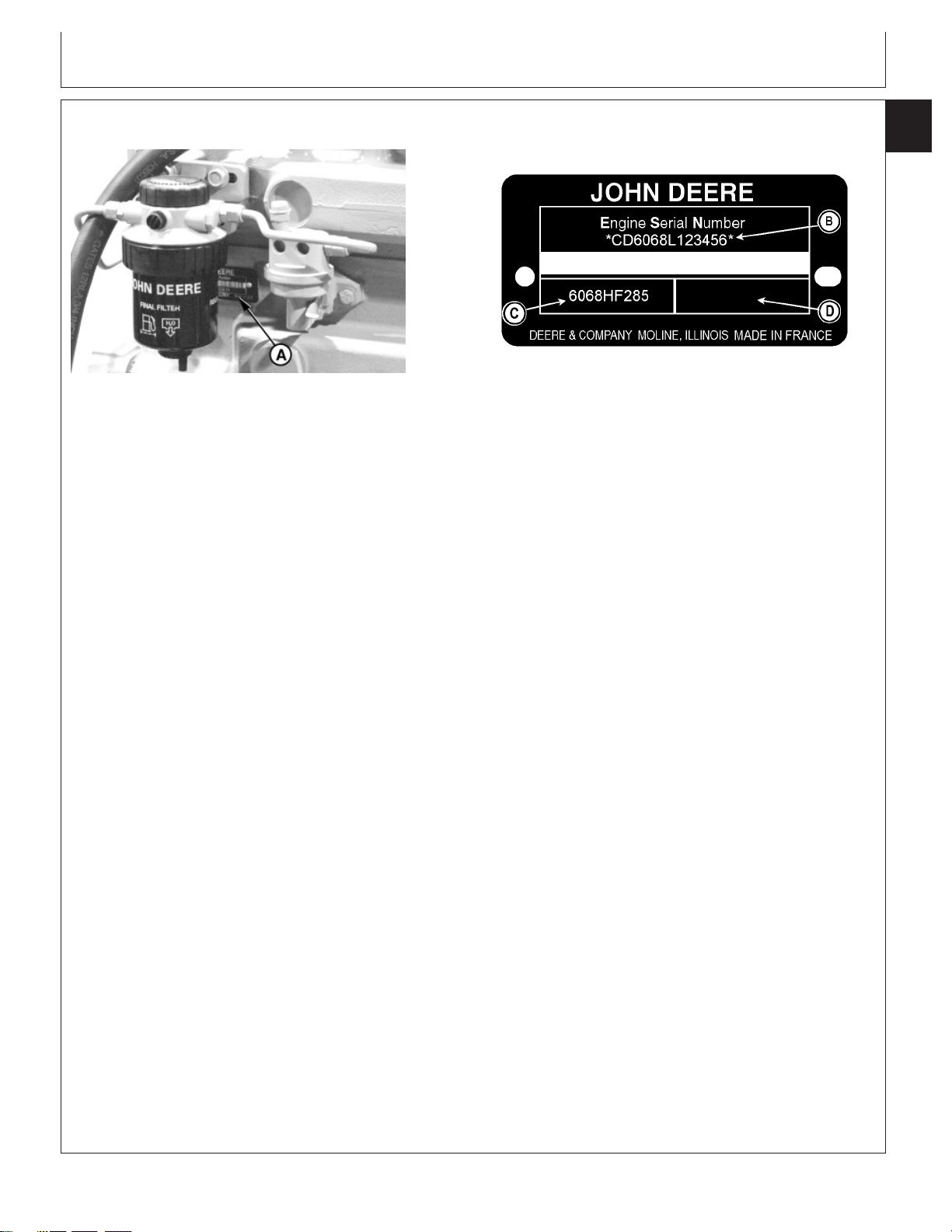
Engine Serial Number Plate Information
Group 001
Engine Identification
01
001
1
RG7778 –UN–11NOV97
A—Engine Serial Number Plate B—Engine Serial Number (13 C—Application Data or Type D—Internal Factory
IMPORTANT: The engine serial number plate can
be easily destroyed. Remove the
plate or record the information
elsewhere, before “hot tank”
digits) Identification (Saran
Each engine has a 13-digit John Deere engine serial
number identifying the producing factory, engine
displacement, emission “Tier” level and sequential
engine number. The following is an example:
Engine Serial Number/Application Data Plate
engines only)
cleaning the block.
Engine Serial Number (B)
CD6068L123456
CD ............................................................ Factory producing engine
6 ................................................................ Number of Cylinders
068 ............................................................ Liter displacement (6.8 liters)
L ................................................................ Emission Tier Level
123456 ...................................................... 6-digit sequential engine number
Factory Producing Engine
CD ............................................................ Saran, France
JO ............................................................. Rosario, Argentina
PE ............................................................. Torreon, Mexico
Emission Tier Level
L, M or N .................................................. Tier 3/Stage IIIA emission certified engine
CD30857 –UN–21AUG06
Engine Application Data (C)
The second line of information on the serial number
plate identifies the engine/machine or OEM
relationship. See ENGINE APPLICATION CHARTS
later in this group. The following is an example:
CTM502 (31MAY07) 01-001-1 4.5 & 6.8 L Level 16 Electronic Fuel System
Continued on next page
CD03523,000016E –19–04MAY07–1/2
060407
PN=23
Page 24

Engine Identification
01
001
6068HF285
2
6 ................................................................ Number of Cylinders
068 ............................................................ Liter displacement (6.8 liters)
H ............................................................... Aspiration code
F ............................................................... User factory code
285 ............................................................ Application code
Aspiration code
A ............................................................... Turbocharged and Air-to-Coolant Aftercooled
D ............................................................... Naturally aspirated
H ............................................................... Turbocharged and Air-to-Air Aftercooled
T ............................................................... Turbocharged, no aftercooling
User Factory Code
AP ............................................................. Industries JohnDeere Mexico S.A. de C.V. (Saltillo/Monterrey, Mexico)
AT ............................................................. Agritalia srl (Vittoria, Sicily, Italy)
BE ............................................................. Bell EquipmnetCo. (Richards Bay, South Africa)
CQ ............................................................ John Deere Brazil (Horizontina, Brazil)
DW ............................................................ John Deere Davenport Works (Davenport, Iowa)
E ............................................................... John Deere Ottumwa Works (Ottumwa, Iowa)
F ............................................................... OEM (Outside Equipment Manufacturers)
FF ............................................................. Deere-Hitachi (Kernersville, North Carolina)
FG ............................................................. Goldoni S.P.A. (Modena, Italy)
FM ............................................................ Marine Engines
FS ............................................................. SDMO Applications
FU ............................................................. Power Unit for Generator Set
H ............................................................... John Deere Harvester Works (East Moline, Illinois)
KV ............................................................. John Deere Commercial Worksite Products (Knoxville, Tennessee/ Dubuque, Iowa)
L ................................................................ John Deere Werke Mannheim (Germany)
LV ............................................................. John Deere Commercial Products (Augusta, Georgia)
N ............................................................... John Deere Des Moines Works (Des Moines, Iowa)
P ............................................................... Industrias John Deere Mexico S.A. de C.V. (Saltillo/Monterrey, Mexico)
PY ............................................................. Larson & Toubro Ltd. (Pune, India)
RW ............................................................ John Deere Waterloo Tractor Works (Waterloo, Iowa)
T ............................................................... John Deere Dubuque Works (Dubuque, Iowa)
T8 ............................................................. Cameco Industries (Thibodaux, Louisiana)
TJ .............................................................. John Deere Forestry (Timberjack, Sweden/Finland/Canada)
YC ............................................................. John Deere Jialian Harvester Co. Limited (China)
Z ............................................................... John Deere WERKE Zweibrucken (Germany)
Application Code
285 etc. ................................................... This is the specific engine model for a given application. In this example (285), “2” denotes
CTM502 (31MAY07) 01-001-2 4.5 & 6.8 L Level 16 Electronic Fuel System
2-valves per cylinder and “85” denotes Tier 3 engines.
CD03523,000016E –19–04MAY07–2/2
060407
PN=24
Page 25
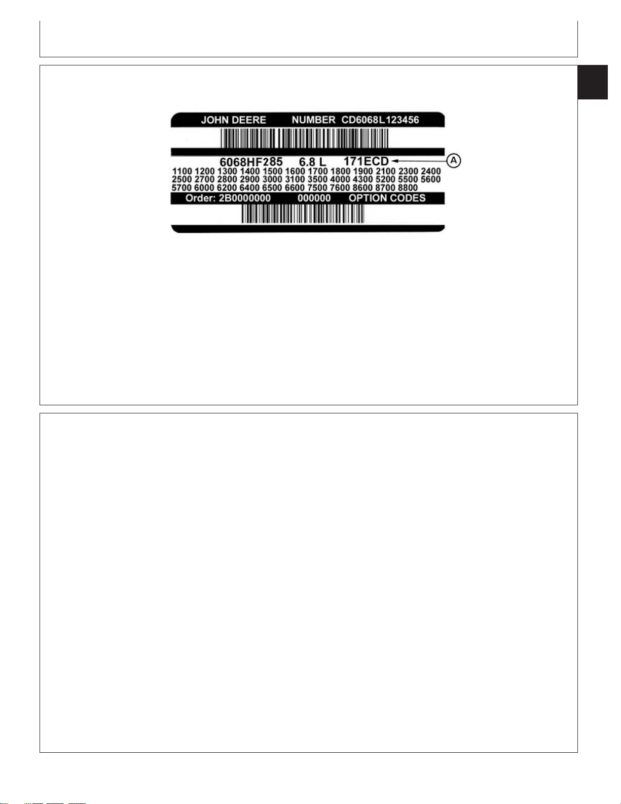
OEM Engine Option Code Label
Engine Identification
01
001
3
OEM Engine Option Code Label
A—Engine Base Code
An option code label is secured to the top of the valve
cover and identifies the factory installed options on
each OEM engine to ensure correct parts acquisition.
Always provide option code information and engine
base code when ordering repair parts. A listing of
Information Relative to Emissions Regulations
Depending on the final destination, engines can meet
the emissions regulations according to the US
Environmental Protection Agency (EPA), California Air
Resources Board (CARB) and for Europe, the
Directive 97/68/EC relating the measures against the
emissions of particles and gaseous pollutant from
internal combustion engines. Such engines are called
“CERTIFIED” and receive an emission label stuck on
the engine.
CD30858 –UN–21AUG06
option codes is given in parts catalogs and operator’s
manuals.
NOTE: Before “hot tank” cleaning, ensure that option
codes are recorded elsewhere.
CD03523,000016F –19–21AUG06–1/1
component where the principle effect of that
component is to bypass, defeat, or render inoperative
any engine component or device which would affect
the engine’s conformance to the emission regulations.
To summarize, it is illegal to do anything except
return the engine to its original published
specifications.
List of emission-related components:
The regulations prohibit tampering with the
emission-related components listed below which would
render that component inoperative or to make any
adjustment on the engine beyond published
specifications. It is also illegal to install a part or
CTM502 (31MAY07) 01-001-3 4.5 & 6.8 L Level 16 Electronic Fuel System
• Fuel injection system
• Intake manifold
• Turbocharger
• Charge air cooling system
• Piston
RG40854,0000007 –19–10APR02–1/1
060407
PN=25
Page 26
01
001
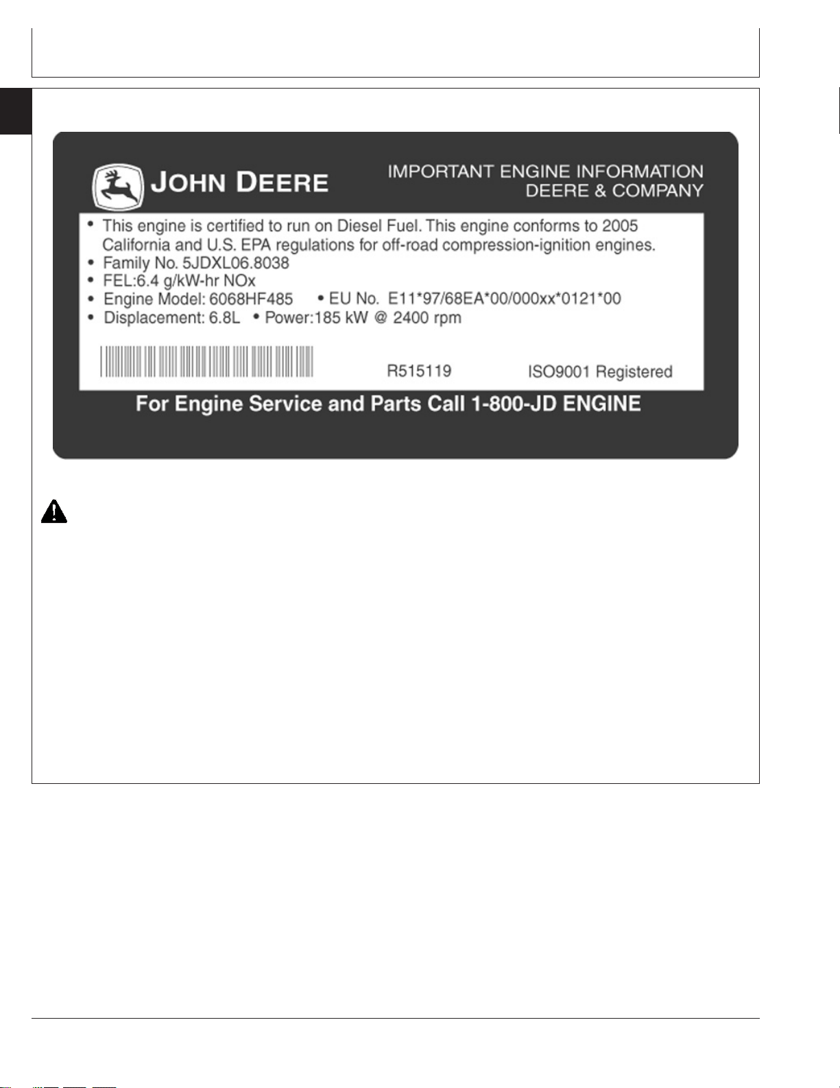
Emissions Control System Certification Label
4
Engine Identification
6.8L Engine Emissions Label
CAUTION: Statutes providing severe
penalties for tampering with emissions
controls may apply at the user’s location.
The emissions warranty described below applies only
to those engines marketed by John Deere that have
been certified by the United States Environmental
Protection Agency (EPA) and/or California Air
Resources Board (CARB); and used in the United
States and Canada. The presence of an emissions
label like the one shown signifies that the engine has
been certified with the EPA and/or CARB. The EPA
and CARB warranties only apply to new engines
RG14852 –UN–26APR06
having the certification label affixed to the engine and
sold as stated above in the geographic areas. The
presence of an EU number in the third line of the label
signifies that the engine has been certified with the
European Union countries per Directive 97/68/EC. The
emissions warranty does not apply to the EU
countries.
NOTE: The hp/kW rating on the engine emissions
certification label specifies the gross engine
hp/kW, which is flywheel power without fan. In
most applications this will not be the same
rating as the advertised vehicle hp/kW rating.
RG19661,000022E –19–17APR07–1/1
CTM502 (31MAY07) 01-001-4 4.5 & 6.8 L Level 16 Electronic Fuel System
060407
PN=26
Page 27
Engine Identification
Engine Application Charts
This component technical manual (CTM502) covers
repair and diagnosis of Level 16 Electronic Fuel
System on PowerTech “E” 4.5 & 6.8 L engines
produced by John Deere SARAN “CD” (France) and
John Deere TORREON “PE” (Mexico). Refer to the
chart below to know which applications are covered by
this manual.
JOHN DEERE AGRICULTURAL EQUIPMENT
Machine Model Engine Model
6230 Advantage Tractor CD4045HL282
6230 Premium Tractor (North America) CD4045HL280
6330 Advantage Tractor CD4045HL283
6330 Premium Tractor (North America) CD4045HL281
6430 Advantage Tractor CD4045HL283
6430 Premium Tractor (North America) CD4045HL281
7130 Advantage Tractor CD6068HL280
7130 Premium Tractor (North America) PE6068HRW72
7230 Advantage Tractor CD6068HL280
7230 Premium Tractor (North America) PE6068HRW72
7330 Premium Tractor (North America) PE6068HRW74
1450 CWS Combine CD6068HCQ82
W330 Combine CD6068HCQ82
NOTE: Information on how to remove and reinstall the
Tractor
Combine
01
001
5
engine in the vehicle is contained in the
relevant machine Technical Manual.
JOHN DEERE CONSTRUCTION and FORESTRY EQUIPMENT
Machine Model Engine Model
Backhoe, Loader
444J Loader PE4045HDW53
544J Loader PE4045HDW70
Crawler Dozer, Crawler Loader
700J Crawler Dozer PE6068HT066
750J Crawler Dozer PE6068HT063
Excavator
160DLC Excavator PE4045HT056
200DLC Excavator PE6068HT069
CTM502 (31MAY07) 01-001-5 4.5 & 6.8 L Level 16 Electronic Fuel System
Continued on next page
CD03523,0000170 –19–23MAY07–1/2
060407
PN=27
Page 28
Engine Identification
01
001
6
Engine Model Application
4045TF285
4045HF285
4045HF279 Generator set
4045HFS73 Generator set
4045HFS82 Generator set
4045HFS83 Generator set
4045HFU79 Generator set
6086HF285
6068HF279 Generator set
6068HFS73 Generator set
6068HFS82 Generator set
6068HFS83 Generator set
6068HFU79 Generator set
JOHN DEERE OEM (OUTSIDE EQUIPMENT MANUFACTURERS)
CD03523,0000170 –19–23MAY07–2/2
CTM502 (31MAY07) 01-001-6 4.5 & 6.8 L Level 16 Electronic Fuel System
060407
PN=28
Page 29

Diesel Fuel
Consult your local fuel distributor for properties of the
diesel fuel available in your area.
Group 002
Fuels, Lubricants, and Coolant
01
002
1
scar diameter of 0.45 mm as measured by ASTM
D6079 or ISO 12156-1.
In general, diesel fuels are blended to satisfy the low
temperature requirements of the geographical area in
which they are marketed.
Diesel fuels specified to EN 590 or ASTM D975 are
recommended.
Required fuel properties
In all cases, the fuel shall meet the following
properties:
Cetane number of 45 minimum. Cetane number
greater than 50 is preferred, especially for
temperatures below -20°C (-4°F) or elevations above
1500 m (5000 ft).
Cold Filter Plugging Point (CFPP) below the
expected low temperature OR Cloud Point at least
5°C(9°F) below the expected low temperature.
Fuel lubricity should pass a minimum level of 3100
grams as measured by ASTM D6078 or maximum
Sulfur content:
• Diesel fuel quality and fuel sulfur content must
comply with all existing emissions regulations for the
area in which the engine operates.
• Use of diesel fuel with sulfur content less than
0.10% (1000 ppm) is STRONGLY recommended.
• Use of diesel fuel with sulfur content 0.10% (1000
ppm to 0.50% (5000 ppm) may result in REDUCED
oil and filter change intervals.
• BEFORE using diesel fuel with sulfur content greater
than 0.50% (5000 ppm), contact your John Deere
dealer.
• DO NOT use diesel fuel with sulfur content greater
than 1.0%.
IMPORTANT: Do not mix used diesel engine oil or
any other type of lubricating oil with
diesel fuel.
IMPORTANT: Improper fuel additive usage may
cause damage on fuel injection
equipment of diesel engines.
DX,FUEL1 –19–17NOV05–1/1
CTM502 (31MAY07) 01-002-1 4.5 & 6.8 L Level 16 Electronic Fuel System
060407
PN=29
Page 30

01
002
Bio-Diesel Fuel
2
Consult your local fuel distributor for properties of the
bio-diesel fuel available in your area.
Fuels, Lubricants, and Coolant
leaving deposits on injectors and in
the combustion chamber.
Bio-diesel fuels may be used ONLY if the bio-diesel
fuel properties meet the latest edition of ASTM D6751,
EN 14214, or equivalent specification.
It is recommended to purchase bio-diesel fuel blended
with B100 from a BQ-9000 Accredited Producer or a
BQ-9000 Certified Marketer as recommended by the
National Bio-diesel Board.
The maximum allowable bio-diesel concentration is a
5% blend (also known as B5) in petroleum diesel fuel.
It has been found that bio-diesel fuels may improve
lubricity in concentrations up to this 5% blend.
When using a blend of bio-diesel fuel, the engine oil
level must be checked daily when the air temperature
is –10°C (14°F) or lower. If oil becomes diluted with
fuel, shorten oil change intervals accordingly.
IMPORTANT: Raw pressed vegetable oils are NOT
acceptable for use as fuel in any
concentration in John Deere
engines.
These oils do not burn completely,
and will cause engine failure by
A major environmental benefit of bio-diesel fuel is its
ability to biodegrade. This makes proper storage and
handling of bio-diesel fuel especially important. Areas
of concern include:
• Quality of new fuel
• Water content of the fuel
• Problems due to aging of the fuel
Potential problems resulting from deficiencies in the
above areas when using bio-diesel fuel in
concentrations above 5% may lead to the following
symptoms:
• Power loss and deterioration of performance
• Fuel leakage
• Corrosion of fuel injection equipment
• Coked and/or blocked injector nozzles, resulting in
engine misfire
• Filter plugging
• Lacquering and/or seizure of internal components
• Sludge and sediments
• Reduced service life of engine components
Consult your fuel supplier for additives to improve
storage and performance of bio-diesel fuels.
DX,FUEL7 –19–14NOV05–1/1
CTM502 (31MAY07) 01-002-2 4.5 & 6.8 L Level 16 Electronic Fuel System
060407
PN=30
Page 31

Fuels, Lubricants, and Coolant
Minimizing the Effect of Cold Weather on Diesel Engines
John Deere diesel engines are designed to operate
effectively in cold weather.
CAUTION: Do not use any starting fluid with
an engine equipped with glow plugs
01
002
3
However, for effective starting and cold weather
operation, a little extra care is necessary. The
information below outlines steps that can minimize the
effect that cold weather may have on starting and
operation of your engine. See your John Deere dealer
for additional information and local availability of cold
weather aids
Use Winter Grade Fuel
When temperatures fall below 5°C (40°F), winter grade
fuel (Grade No. 1-D fuel in North America) is best
suited for cold weather operation. Winter grade fuel
has a lower cloud point and a lower pour point.
Cloud point is the temperature at which wax will begin
to form in the fuel and this wax causes fuel filters to
plug. Pour point is the temperature at which fuel
begins to thicken and becomes more resistant to flow
through fuel pumps and lines.
NOTE: On an average, winter grade fuel has a lower
BTU (heat content) rating. Using winter grade
fuel may reduce power and fuel efficiency, but
should not cause any other engine
performance effects. Check the grade of fuel
being used before troubleshooting for low
power complaints in cold weather operation.
Coolant Heater
An engine block heater (coolant heater) is an available
option to aid cold weather starting.
Seasonal Viscosity Oil and Proper Coolant
Concentration
Use seasonal grade viscosity engine oil based ion the
expected air temperature range between oil changes
and proper concentration of low silicate antifreeze as
recommended. (See DIESEL ENGINE OIL and
ENGINE COOLANT requirements this section.)
Diesel Fuel Flow Additive
Use John Deere Premium Diesel Fuel Conditioner
(Winter) or equivalent to treat fuel during the cold
weather season. This winter formulation is a
combination diesel fuel conditioner and anti-gel
additive.
IMPORTANT: Treat fuel when outside temperature
drops below 0°C (32°F). For best
results, use with untreated fuel.
Follow all recommended instructions
on label.
Air Intake Heater
An air intake heater is an available option to aid cold
weather starting.
Winterfronts
Use of fabric, cardboard , or solid winterfronts is not
recommended with any John Deere engine. Their use
can result in excessive engine coolant, oil, and charge
air temperatures. This can lead to reduced engine life,
CAUTION: Do not use any starting fluid with
an air intake heater.
loss of power and poor fuel economy. Winterfronts
may also put abnormal stress on fan and fan drive
components potentially causing premature failures.
Starting Fluid
A starting fluid port on the intake is available to aid
cold weather starting.
Continued on next page
CTM502 (31MAY07) 01-002-3 4.5 & 6.8 L Level 16 Electronic Fuel System
DX,FUEL10 –19–16DEC05–1/2
060407
PN=31
Page 32

Fuels, Lubricants, and Coolant
01
002
If winterfronts are used, they should never totally close
4
off the grill frontal area. Approximately 25% area in the
center of the grill should remain open at all times. At
no time should the air blockage device be applied
directly to the radiator core.
Radiator Shutters
If equipped with a thermostatically controlled radiator
shutter system, this system should be regulated in
such a way that the shutters are completely open by
Handling and Storing Diesel Fuel
the time the coolant reaches 93°C (200°F) to prevent
excessive intake manifold temperatures. Manually
controlled systems are not recommended.
If air-to-air aftercooling is used, the shutters must be
completely open by the time the intake manifold air
temperature reaches the maximum allowable
temperature out of the charge air cooler.
For more information, see your John Deere dealer.
DX,FUEL10 –19–16DEC05–2/2
CAUTION: Handle fuel carefully. Do not fill
the fuel tank when engine is running.
DO NOT smoke while you fill the fuel tank or
service the fuel system.
Fill the fuel tank at the end of each day’s operation to
prevent water condensation and freezing during cold
weather.
Keep all storage tanks as full as practicable to
minimize condensation.
Ensure that all fuel tank caps and covers are installed
properly to prevent moisture from entering.
Monitor water content of the fuel regularly.
When using bio-diesel fuel, the fuel filter may require
more frequent replacement due to premature plugging.
Check engine oil level daily prior to starting engine. A
rising oil level may indicate fuel dilution of the engine
oil.
IMPORTANT: The fuel tank is vented through the
filler cap. If a new filler cap is
required, always replace it with an
original vented cap.
When fuel is stored for an extended period or if there
is a slow turnover of fuel, add a fuel conditioner to
stabilize the fuel and prevent water condensation.
Contact your fuel supplier for recommendations.
DX,FUEL4 –19–19DEC03–1/1
CTM502 (31MAY07) 01-002-4 4.5 & 6.8 L Level 16 Electronic Fuel System
060407
PN=32
Page 33

Fuels, Lubricants, and Coolant
Lubricity of Diesel Fuel
Most diesel fuels manufactured in the United States,
Canada, and the European Union have adequate
lubricity to ensure proper operation and durability of
fuel injection system components. However, diesel
fuels manufactured in some areas of the world may
lack the necessary lubricity.
IMPORTANT: Make sure the diesel fuel used in
your machine demonstrates good
lubricity characteristics.
Testing Diesel Fuel
01
002
5
Fuel lubricity should pass a minimum load level of
3100 grams as measured by ASTM D6078 or a
maximum scar diameter of 0.45 mm as measured by
ASTM D6079 or ISO 12156-1.
If fuel of low or unknown lubricity is used, add John
Deere PREMIUM DIESEL FUEL CONDITIONER (or
equivalent) at the specified concentration.
DX,FUEL5 –19–27OCT05–1/1
DIESELSCAN is a John Deere fuel analysis program
that can be used to monitor the quality of your fuel. The
DIESELSCAN analysis verifies fuel type, cleanliness,
water content, suitability for cold weather operation, and
whether the fuel meets specifications.
Check with your John Deere dealer for availability of
DIESELSCAN kits.
DIESELSCAN is a trademark of Deere & Company
Engine Oil and Filter Service Intervals
See applicable operator’s manual for service intervals.
DX,FUEL6 –19–14NOV05–1/1
DM80898,000025E –19–27NOV06–1/1
CTM502 (31MAY07) 01-002-5 4.5 & 6.8 L Level 16 Electronic Fuel System
060407
PN=33
Page 34

Fuels, Lubricants, and Coolant
01
002
Diesel Engine Oil
6
Use oil viscosity based on the expected air temperature
range during the period between oil changes.
o
50 C
o
40 C
o
122 F
o
104 F
John Deere PLUS-50 oil is preferred.
Oils meeting one of the following specifications are also
recommended:
• ACEA Oil Sequence E7
• ACEA Oil Sequence E6
Extended service intervals may apply when John Deere
PLUS-50, ACEA E7, or ACEA E6 engine oils are used.
Consult your John Deere dealer for more information.
Other oils may be used if they meet one or more of the
following:
• John Deere TORQ-GARD SUPREME
• API Service Category CJ-4
• API Service Category CI-4 PLUS
• API Service Category CI-4
• ACEA Oil Sequence E5
• ACEA Oil Sequence E4
Multi-viscosity diesel engine oils are preferred.
SAE 15W-40
SAE 10W-40
SAE 10W-30
o
30 C
o
20 C
o
10 C
o
0 C
o
-10 C
o
-20 C
o
-30 C
o
-40 C
o
86 F
o
68 F
o
50 F
o
32 F
o
14 F
o
-4 F
o
-22 F
o
-40 F
SAE 0W-40
SAE 5W-30
Oil Viscosities for Air Temperature Ranges
TS1684 –UN–09OCT06
Diesel fuel quality and fuel sulfur content must comply
with all existing emissions regulations for the area in
which the engine operates.
DO NOT use diesel fuel with sulfur content greater than
1.0% (10 000 ppm).
PLUS-50 is a trademark of Deere & Company
TORQ-GARD SUPREME is a trademark of Deere & Company
DX,ENOIL11 –19–13SEP06–1/1
CTM502 (31MAY07) 01-002-6 4.5 & 6.8 L Level 16 Electronic Fuel System
060407
PN=34
Page 35

Fuels, Lubricants, and Coolant
Diesel Engine Break-In Oil
New engines are filled at the factory with John Deere
ENGINE BREAK-IN OIL. During the break-in period,
add John Deere ENGINE BREAK-IN OIL as needed to
maintain the specified oil level.
Change the oil and filter after the first 100 hours of
operation of a new or rebuilt engine.
After engine overhaul, fill the engine with John Deere
ENGINE BREAK-IN OIL.
If John Deere ENGINE BREAK-IN OIL is not available,
use a diesel engine oil meeting one of the following
during the first 100 hours of operation:
• API Service Classification CE
• API Service Classification CD
• API Service Classification CC
• ACEA Oil Sequence E2
• ACEA Oil Sequence E1
01
002
7
After the break-in period, use John Deere PLUS-50
or other diesel engine oil as recommended in this
manual.
IMPORTANT: Do not use PLUS-50 oil or engine
oils meeting any of the following
during the first 100 hours of
operation of a new or rebuilt engine:
API CJ-4 ACEA E7
API CI-4 PLUS ACEA E6
API CI-4 ACEA E5
API CH-4 ACEA E4
API CG-4 ACEA E3
API CF-4
API CF-2
API CF
These oils will not allow the engine
to break-in properly.
PLUS-50 is a trademark of Deere & Company.
DX,ENOIL4 –19–13SEP06–1/1
Oil Filters
Filtration of oils is critical to proper operation and
lubrication.
Always change filters regularly as specified in this manual.
Use filters meeting John Deere performance
specifications.
DX,FILT –19–18MAR96–1/1
CTM502 (31MAY07) 01-002-7 4.5 & 6.8 L Level 16 Electronic Fuel System
060407
PN=35
Page 36

Fuels, Lubricants, and Coolant
01
002
Alternative and Synthetic Lubricants
8
Conditions in certain geographical areas may require
lubricant recommendations different from those printed
in this manual.
Some John Deere brand coolants and lubricants may
not be available in your location.
Synthetic lubricants may be used if they meet the
performance requirements as shown in this manual.
The temperature limits and service intervals shown in
this manual apply to both conventional and synthetic
oils.
Consult your John Deere dealer to obtain information
and recommendations.
Lubricant Storage
Your equipment can operate at top efficiency only
when clean lubricants are used.
Use clean containers to handle all lubricants.
Whenever possible, store lubricants and containers in
an area protected from dust, moisture, and other
contamination. Store containers on their side to avoid
water and dirt accumulation.
Re-refined base stock products may be used if the
finished lubricant meets the performance requirements.
DX,ALTER –19–15JUN00–1/1
Make certain that all containers are properly marked to
identify their contents.
Properly dispose of all old containers and any residual
lubricant they may contain.
DX,LUBST –19–18MAR96–1/1
Mixing of Lubricants
In general, avoid mixing different brands or types of oil.
Oil manufacturers blend additives in their oils to meet
certain specifications and performance requirements.
Mixing different oils can interfere with the proper
functioning of these additives and degrade lubricant
performance.
CTM502 (31MAY07) 01-002-8 4.5 & 6.8 L Level 16 Electronic Fuel System
Consult your John Deere dealer to obtain specific
information and recommendations.
DX,LUBMIX –19–18MAR96–1/1
060407
PN=36
Page 37

Fuels, Lubricants, and Coolant
Grease
Use grease based on NLGI consistency numbers and the
expected air temperature range during the service interval.
John Deere SD POLYUREA GREASE is preferred.
The following greases are also recommended
• John Deere HD LITHIUM COMPLEX GREASE
• John Deere HD WATER RESISTANT GREASE
• John Deere GREASE-GARD
Other greases may be used if they meet the following:
NLGI Performance Classification GC-LB
IMPORTANT: Some types of grease thickeners are
not compatible with others. Consult
your grease supplier before mixing
different types of grease
01
002
9
TS1673 –UN–31OCT03
GREASE-GARD is a trademark of Deere & Company
DX,GREA1 –19–07NOV03–1/1
CTM502 (31MAY07) 01-002-9 4.5 & 6.8 L Level 16 Electronic Fuel System
060407
PN=37
Page 38

Fuels, Lubricants, and Coolant
01
002
Diesel Engine Coolant
10
The engine cooling system is filled to provide
year-round protection against corrosion and cylinder
liner pitting, and winter freeze protection to -37°C
(-34°F). If protection at lower temperatures is required,
consult your John Deere dealer for recommendations.
John Deere COOL-GARD Prediluted Coolant is
preferred for service.
John Deere COOL-GARD Prediluted Coolant is
available in a concentration of either 50% ethylene
glycol or 55% propylene glycol.
Additional recommended coolants
The following engine coolant is also recommended:
Other low silicate ethylene glycol base coolants for
heavy-duty engines may also be used if they meet one
of the following specifications:
• ASTM D4985 ethylene glycol base prediluted (50%)
coolant
• ASTM D4985 ethylene glycol base coolant
concentrate in a 40% to 60% mixture of concentrate
with quality water
Coolants meeting ASTM D4985 require an initial
charge of supplemental coolant additives, formulated
for protection of heavy duty diesel engines against
corrosion and cylinder liner erosion and pitting. They
also require periodic replenishment of additives during
the drain interval.
• John Deere COOL-GARD Coolant Concentrate in a
40% to 60% mixture of concentrate with quality
water.
John Deere COOL-GARD coolants do not require use
of supplemental coolant additives, except for periodic
replenishment of additives during the drain interval.
Other fully formulated coolants
Other fully formulated low silicate ethylene or
propylene glycol base coolants for heavy-duty engines
may be used if they meet one of the following
specifications:
• ASTM D6210 prediluted (50%) coolant
• ASTM D6210 coolant concentrate in a 40% to 60%
mixture of concentrate with quality water
Coolants meeting ASTM D6210 do not require use of
supplemental coolant additives, except for periodic
replenishment of additives during the drain interval.
Coolants requiring supplemental coolant additives
Other coolants
It is possible that neither John Deere COOL-GARD nor
coolants meeting one of the coolant standards listed
above is available in the geographical area where
service is performed. If these coolants are unavailable,
use a coolant concentrate or prediluted coolant with a
quality additive package that provides cylinder liner
cavitation protection and protects the cooling system
metals (cast iron, aluminum alloys, and copper alloys
such as brass) from corrosion.
The additive package must be part of one of the
following coolant mixtures:
• ethylene glycol or propylene glycol base prediluted
(40% to 60%) coolant
• ethylene glycol or propylene glycol base coolant
concentrate in a 40% to 60% mixture of concentrate
with quality water
Water quality
COOL-GARD is a trademark of Deere & Company
Continued on next page
DX,COOL3 –19–27OCT05–1/2
CTM502 (31MAY07) 01-002-10 4.5 & 6.8 L Level 16 Electronic Fuel System
060407
PN=38
Page 39

Fuels, Lubricants, and Coolant
Water quality is important to the performance of the
cooling system. Distilled, deionized, or demineralized
water is recommended for mixing with ethylene glycol
and propylene glycol base engine coolant concentrate.
IMPORTANT: Do not use cooling system sealing
additives or antifreeze that contains
sealing additives.
Supplemental Coolant Additives
IMPORTANT: Do not mix ethylene glycol and
propylene glycol base coolants.
DX,COOL3 –19–27OCT05–2/2
01
002
11
The concentration of coolant additives is gradually
depleted during engine operation. For all
recommended coolants, replenish additives between
drain intervals by adding a supplemental coolant
additive every 12 months or as determined necessary
by coolant testing.
John Deere COOLANT CONDITIONER is
recommended as a supplemental coolant additive in
John Deere engines.
IMPORTANT: Do not add a supplemental coolant
additive when the cooling system is
drained and refilled with John
DeereCOOL-GARD.
COOL-GARD is a trademark of Deere & Company
If other coolants are used, consult the coolant supplier
and follow the manufacturer’s recommendation for use
of supplemental coolant additives.
The use of non-recommended supplemental coolant
additives may result in additive drop-out and gelation
of the coolant.
Add the manufacturer’s recommended concentration of
supplemental coolant additive. DO NOT add more than
the recommended amount.
DX,COOL4 –19–07NOV03–1/1
CTM502 (31MAY07) 01-002-11 4.5 & 6.8 L Level 16 Electronic Fuel System
060407
PN=39
Page 40

01
002
Operating in Warm Temperature Climates
12
John Deere engines are designed to operate using
glycol base engine coolants.
Always use a recommended glycol base engine
coolant, even when operating in geographical areas
where freeze protection is not required.
IMPORTANT: Water may be used as coolant in
emergency situations only.
Fuels, Lubricants, and Coolant
Foaming, hot surface aluminum and
iron corrosion, scaling, and
cavitation will occur when water is
used as the coolant, even when
coolant conditioners are added.
Drain cooling system and refill with
recommended glycol base engine
coolant as soon as possible.
DX,COOL6 –19–18MAR96–1/1
CTM502 (31MAY07) 01-002-12 4.5 & 6.8 L Level 16 Electronic Fuel System
060407
PN=40
Page 41

Fuels, Lubricants, and Coolant
Additional Information About Diesel Engine Coolants and Supplemental Coolant Additives
01
002
13
Engine coolants are a combination of three chemical
components: ethylene glycol or propylene glycol
antifreeze, inhibiting coolant additives, and quality
water.
Coolant specifications
Some products, including John Deere COOL-GARD
Prediluted Coolant, are fully formulated coolants that
contain all three components in their correct
concentrations. Do not add an initial charge of
supplemental coolant additives to these fully
formulated products.
Coolants meeting ASTM D6210 do not require an
initial charge of supplemental coolant additives.
Some coolant concentrates, including John Deere
COOL-GARD Coolant Concentrate, contain both glycol
antifreeze and inhibiting coolant additives. Mix these
products with quality water, but do not add an initial
charge of supplemental coolant additives.
Coolants meeting ASTM D4985 require an initial
charge of supplemental coolant additives.
Replenish coolant additives
simple mixture of ethylene glycol or propylene glycol
and water will not give adequate protection.
Use of supplemental coolant additives reduces
corrosion, erosion, and pitting. These chemicals
reduce the number of vapor bubbles in the coolant and
help form a protective film on cylinder liner surfaces.
This film acts as a barrier against the harmful effects
of collapsing vapor bubbles.
Avoid automotive-type coolants
Never use automotive-type coolants (such as those
meeting ASTM D3306). These coolants do not contain
the correct additives to protect heavy-duty diesel
engines. They often contain a high concentration of
silicates and may damage the engine or cooling
system.
Water quality
Water quality is important to the performance of the
cooling system. Distilled, deionized, or demineralized
water is recommended for mixing with ethylene glycol
and propylene glycol base engine coolant concentrate.
All water used in the cooling system should meet the
following minimum specifications for quality:
The concentration of coolant additives is gradually
depleted during engine operation. Periodic
replenishment of inhibitors is required, even when
John Deere COOL-GARD or another fully formulated
coolant is used. Follow the recommendations in this
manual for the use of supplemental coolant additives.
Why use supplemental coolant additives?
Operating without proper coolant additives will result in
increased corrosion, cylinder liner erosion and pitting,
Chlorides <40 mg/L
Sulfates <100 mg/L
Total dissolved solids <340 mg/L
Total hardness <170 mg/L
pH 5.5 to 9.0
Freeze protection
The relative concentrations of glycol and water in the
engine coolant determine its freeze protection limit.
and other damage to the engine and cooling system. A
COOL-GARD is a trademark of Deere & Company
Continued on next page
CTM502 (31MAY07) 01-002-13 4.5 & 6.8 L Level 16 Electronic Fuel System
DX,COOL7 –19–19DEC03–1/2
060407
PN=41
Page 42

01
002
14
Ethylene Glycol Freeze Protection Limit
40% -24°C (-12°F)
50% -37°C (-34°F)
60% -52°C (-62°F)
Propylene Glycol Freeze Protection Limit
40% -21°C (-6°F)
50% -33°C (-27°F)
60% -49°C (-56°F)
Testing Diesel Engine Coolant
Fuels, Lubricants, and Coolant
DO NOT use a coolant-water mixture greater than
60% ethylene glycol or 60% propylene glycol.
DX,COOL7 –19–19DEC03–2/2
Testing Diesel Engine Coolant
Maintaining adequate concentrations of glycol and
inhibiting additives in the coolant is critical to protect
the engine and cooling system against freezing,
corrosion, and cylinder liner erosion and pitting.
Test the coolant solution at intervals of 12 months or
less and whenever excessive coolant is lost through
leaks or overheating.
Coolant test strips
Coolant test strips are available from your John Deere
dealer. These test strips provide a simple, effective
COOLSCAN is a trademark of Deere & Company
COOLSCAN PLUS is a trademark of Deere & Company
method to check the freeze point and additive levels of
your engine coolant.
Compare the results to the supplemental coolant
additive (SCA) chart to determine the amount of
inhibiting additives in your coolant and whether more
John Deere COOLANT CONDITIONER should be
added.
COOLSCAN and COOLSCAN PLUS
For a more thorough evaluation of your coolant,
perform a COOLSCAN or COOLSCAN PLUS analysis,
where available. See your John Deere dealer for
information.
DX,COOL9 –19–19DEC03–1/1
CTM502 (31MAY07) 01-002-14 4.5 & 6.8 L Level 16 Electronic Fuel System
060407
PN=42
Page 43

Fuels, Lubricants, and Coolant
Drain Intervals for Diesel Engine Coolant
Drain the factory fill engine coolant, flush the cooling
system, and refill with new coolant after the first 3
years or 3000 hours of operation.
01
002
15
operation, provided that the coolant is tested annually
AND additives are replenished, as needed, by adding
a supplemental coolant additive.
Subsequent drain intervals are determined by the
coolant used for service. At each interval, drain the
coolant, flush the cooling system, and refill with new
coolant.
When John Deere COOL-GARD is used, the drain
interval may be extended to 5 years or 5000 hours of
COOL-GARD is a trademark of Deere & Company
If John Deere COOL-GARD is used but the coolant is
not tested OR additives are not replenished by adding
a supplemental coolant additive, the drain interval is 3
years or 3000 hours of operation
If COOL-GARD is not used, the drain interval is
reduced to 2 years or 2000 hours of operation.
DX,COOL11 –19–19DEC03–1/1
CTM502 (31MAY07) 01-002-15 4.5 & 6.8 L Level 16 Electronic Fuel System
060407
PN=43
Page 44

01
002
16
Fuels, Lubricants, and Coolant
CTM502 (31MAY07) 01-002-16 4.5 & 6.8 L Level 16 Electronic Fuel System
060407
PN=44
Page 45

Section 02
Repair and Adjustments
Page Page
Group 090—Electronic Fuel System Repair and
Adjustments
Fuel System - General Information .........02-090-1
Relieve Fuel System Pressure ............02-090-1
Fuel System Components ................02-090-2
Replace Fuel Filter Element (Primary or
Final) ..............................02-090-3
Remove and Install Fuel Filter Base (Primary
and Final) ..........................02-090-5
Remove Fuel Transfer Pump .............02-090-6
Install Fuel Transfer Pump ...............02-090-7
Remove and Install High Pressure Fuel
Pump..............................02-090-8
Remove and Install Suction Control Valve. . . 02-090-12
Remove and Install High Pressure
Common Rail .......................02-090-16
Remove and Install Flow Dampers ........02-090-17
Remove and Install Pressure Limiter.......02-090-19
Remove and Install Fuel Injection Wire
Harness Assembly ...................02-090-21
Injector Identification Tag Information ......02-090-25
Remove Electronic Injector (EI) ...........02-090-26
Clean Electronic Injector (EI) Bore ........02-090-29
Clean Electronic Injector (EI) Orifice .......02-090-29
Clean Electronic Injector (EI) Body ........02-090-29
Inspect Electronic Injector (EI) Body .......02-090-29
Install Electronic Injector (EI) .............02-090-30
Remove and Install Fuel Leak-Off Line .....02-090-34
Contents
Remove and Install Fuel Transfer Pump
Pressure Sensor .....................02-110-7
Remove and Install Crankshaft Position
Sensor .............................02-110-8
Remove and Install Pump Position Sensor . . .02-110-8
Remove and Install Water-In-Fuel (WIF)
Sensor .............................02-110-9
Install Wiring Harness for Engine Mount
ECU..............................02-110-10
Install Wiring Harness for Remote ECU ....02-110-18
Connectors ..........................02-110-29
Connector Repair .....................02-110-30
Repair WEATHERPACK Connector ......02-110-31
Repair Cinch Flex Box Connector .........02-110-34
METRI-PACK(Push Type) .............02-110-42
Repair HD Series DEUTSCH Connectors . . .02-110-44
Repair SUMITOMO Connectors .........02-110-47
02
Group 110—Electronic Engine Control Repair and
Engine Control Unit (ECU) Maintenance .....02-110-1
Remove and Install Engine Control Unit
(ECU) on Engine (Optional Equipment) ....02-110-2
Remove and Install Adaptation Parts for
Engine Control Unit (ECU) Mounted on
Engine (Optional Equipment) ............02-110-3
Remove and Install Engine Coolant
Temperature (ECT) Sensor .............02-110-4
Remove and Install Fuel Temperature
Sensor .............................02-110-4
Remove and Install Manifold Air Temperature
(MAT) Sensor .......................02-110-5
Remove and Install Oil Pressure Sensor .....02-110-5
Remove and Install Fuel Rail Pressure
Sensor .............................02-110-6
CTM502 (31MAY07) 02-1 4.5 & 6.8 L Level 16 Electronic Fuel System
Adjustment
060407
PN=1
Page 46

02
Contents
CTM502 (31MAY07) 02-2 4.5 & 6.8 L Level 16 Electronic Fuel System
060407
PN=2
Page 47

Electronic Fuel System Repair and Adjustments
Fuel System - General Information
Group 090
The Level 16 Engine Control Unit (ECU) is used to
control the High Pressure Common Rail (HPCR) fuel
system. The HPCR fuel system includes the high
pressure fuel pump, high pressure common rail, and
electronic injectors.
The electronic injectors can not be serviced. If any part
of the component fails, the entire injector must be
replaced.
Electronic injectors cannot be tested for opening
pressure, as they are controlled electronically.
Relieve Fuel System Pressure
CAUTION: High-pressure fluid remaining in fuel
lines can cause serious injury. Before
disconnecting fuel lines, sensors, or any other
components between the high-pressure fuel
pump and nozzles on engines with High
Pressure Common Rail (HPCR) fuel system,
wait a minimum of 15 minutes after engine is
stopped.
When servicing injectors it is important to complete the
injector calibration procedure. Each injector has a
specific calibration and this information can be
obtained by scanning the bar code on the service
injector box and downloading the injector information
from the John Deere Custom Performance web site.
An alternative is to enter the injector serial number and
part number stamped on the injector. If the ECU is not
programmed with the correct information for each
injector and the correct cylinder that it is in then engine
performance and emissions will be affected.
CD03523,0000172 –19–15FEB07–1/1
02
090
1
Any time the fuel system has been opened up for service
TS1343 –UN–18MAR92
(lines disconnected or filters removed), it will be necessary
to bleed air from the system. See BLEED THE FUEL
SYSTEM in Section 04, Group 150 in this manual.
CD03523,0000173 –19–22AUG06–1/1
CTM502 (31MAY07) 02-090-1 4.5 & 6.8 L Level 16 Electronic Fuel System
060407
PN=47
Page 48

Fuel System Components
02
090
2
Electronic Fuel System Repair and Adjustments
Fuel system components
A—Primary fuel filter E—High pressure common rail H—Fuel pressure sensor L—Fuel supply line
B—Fuel transfer pump (HPCR) I—Electronic injector (EI) M—Pump-to-rail high pressure
C—Final fuel filter F—Flow damper J—Fuel leak-off line line
D—High pressure fuel pump G—Fuel pressure limiter K—Wiring harness N—High pressure delivery line
CD03523,000017A –19–09OCT06–1/1
CD30897 –UN–05OCT06
CTM502 (31MAY07) 02-090-2 4.5 & 6.8 L Level 16 Electronic Fuel System
060407
PN=48
Page 49

Electronic Fuel System Repair and Adjustments
Replace Fuel Filter Element (Primary or Final)
02
090
3
Fuel filter typical location
CD30859 –UN–07SEP06
NOTE: Refer to operator’s manual for proper servicing
and (hourly) replacement intervals.
1. When applicable, disconnect water-in-fuel connector
(H).
2. Loosen retaining ring (C) by lifting it, and remove filter
element (D).
NOTE: To avoid spilling of fuel, seal old filter element
using plug from new element.
3. If equipped, remove sediment glass bowl (E) from
previous filter element and reinstall it onto the new
element.
IMPORTANT: Install fuel filter element dry. Do not
prefill new fuel filters as it could
contaminate fuel system with unfiltered
fuel.
4. Install dust seal (F) as shown.
Replace fuel filter element - Exploded view
CD30860 –UN–07SEP06
A—Primary fuel filter
B—Final fuel filter
C—Retaining ring
D—Filter element
E—Sediment bowl
F—Dust seal
G—Drain screw
H—Water-in-fuel connector
I—Bleed screw
CTM502 (31MAY07) 02-090-3 4.5 & 6.8 L Level 16 Electronic Fuel System
Replace fuel filter element - Dust seal
Continued on next page
CD30667 –UN–17JUN98
CD03523,0000174 –19–19DEC06–1/2
060407
PN=49
Page 50

Electronic Fuel System Repair and Adjustments
5. Position the new filter element in proper location inside
the mounting base then tighten retaining ring about 1/3
turn until ring fits into the detent. DO NOT overtighten.
6. If applicable, connect water-in-fuel connector (H).
02
090
7. Bleed fuel system.
4
CD03523,0000174 –19–19DEC06–2/2
CTM502 (31MAY07) 02-090-4 4.5 & 6.8 L Level 16 Electronic Fuel System
060407
PN=50
Page 51

Electronic Fuel System Repair and Adjustments
Remove and Install Fuel Filter Base (Primary and Final)
02
090
5
Fuel filter mounting base (primary and final)
A—Fuel lines C—Fitting E—Bracket G—Fuel filter base
B—Fuel filter base-to-engine D—Plug F—Bracket-to-cylinder head
cap screws cap screw
NOTE: Fuel filter base can be removed with or without
filter element installed.
1. Disconnect fuel lines (A).
NOTE: Fuel lines may be connected to different inlet
and outlet ports depending on application.
5. Install fittings (C) and plugs (D), or optional
CD30861 –UN–24AUG06
accessories like fuel pressure sensor or fuel heater,
2. Loosen cap screws (B) and remove fuel filter base
on filter base as required. Tighten to specification.
(G).
Specification
3. Remove bracket (E) from cylinder head if needed.
4. Replace and reinstall parts as necessary. Tighten
cap screws to specification.
Fuel filter base—Specification
Bracket-to-cylinder head cap
screw—Torque 70 N•m (52 lb-ft)..........................................................
Fuel filter base-to-bracket cap
screw—Torque 50 N•m (37 lb-ft)..........................................................
Fittings,plugs or
accessories-to-fuel filter base—
Torque 10 N•m (7 lb-ft).........................................................................
6. Install fuel lines then tighten tube nuts until seated
on fitting shoulder.
7. If previously removed, install filter element then
bleed fuel system.
CTM502 (31MAY07) 02-090-5 4.5 & 6.8 L Level 16 Electronic Fuel System
CD03523,0000175 –19–08SEP06–1/1
060407
PN=51
Page 52

Electronic Fuel System Repair and Adjustments
Remove Fuel Transfer Pump
IMPORTANT: A backup wrench must always be used
when disconnecting fittings or fuel lines
02
090
6
1. Disconnect fuel inlet line (A) and outlet line (B) and cap
connections on fuel transfer pump and fuel lines to
keep debris out of fuel system.
from supply pump to avoid damage to
fittings.
2. Remove cap screws (C) and remove fuel transfer
pump assembly from cylinder block.
NOTE: The fuel transfer pump is driven by a push rod (D)
that rides on an eccentric camshaft lobe. The
cylinder head must be removed to remove this
push rod.
3. Cover opening on cylinder block to prevent dirt from
entering the engine.
4. Inspect face of pump lever for wear. If lever face is
worn flat or concave, replace pump.
A—Transfer Pump Inlet from Pre-Filter
B—Transfer Pump Outlet to Final Fuel Filter
C—Cap Screws
D—Push Rod
Mechanical Fuel Transfer Pump Supply Lines
RG12453A –UN–14JUN02
RG9051 –UN–16MAR98
Remove Mechanical Fuel Transfer Pump
Mechanical Fuel Transfer Pump Push Rod
RG41183,00000CF –19–22JAN07–1/1
CTM502 (31MAY07) 02-090-6 4.5 & 6.8 L Level 16 Electronic Fuel System
RG12022 –UN–27NOV01
060407
PN=52
Page 53

Install Fuel Transfer Pump
Assemble Fuel Transfer Pump
Electronic Fuel System Repair and Adjustments
NOTE: If transfer pump is being replaced, inlet fitting (A)
and outlet fitting (B) as well as respective O-rings
(C) are not provided with the pump.
1. Remove and retain inlet (A) and outlet (B) fittings from
old pump. Discard O-rings (C).
2. Install new O-rings and fittings into new transfer pump.
Tighten fittings to specification.
Specification
Inlet and outlet fitting-to-fuel
transfer pump—Torque 10 N•m (7 lb-ft).....................................................
IMPORTANT: Apply LOCTITE 242 to threads of supply
pump mounting cap screws (C) and fuel
line fittings when reinstalling supply
pump. DO NOT allow sealant to get into
fuel system.
1. Install the fuel transfer pump to cylinder block with
pumping lever resting on top of push rod, using a new
O-ring. Tighten cap screws (C) to specifications.
02
090
7
CD30924 –UN–18OCT06
Assemble Fuel Transfer Pump
A—Inlet fitting
B—Oulet fitting
C—O-ring
RG41183,00000D0 –19–18OCT06–1/2
Fuel Transfer Pump Cap
Screws—Torque 30 N•m (22 lb-ft)..............................................................
IMPORTANT: Always use a backup wrench when
installing fittings and/or fuel lines onto
supply pump to avoid damage to
Specification
RG12453A –UN–14JUN02
Fuel Transfer Pump Lines
A—Fuel Transfer Pump Inlet from Pre-filter
B—Fuel Transfer Pump Outlet to Final Fuel Filter
C—Cap Screws
fittings.
2. Connect supply pump inlet line (A) and outlet line (B)
and tighten tube nut until seated on fitting shoulder.
3. Bleed the fuel system. See BLEED THE FUEL
SYSTEM later in this Group.
RG41183,00000D0 –19–18OCT06–2/2
CTM502 (31MAY07) 02-090-7 4.5 & 6.8 L Level 16 Electronic Fuel System
060407
PN=53
Page 54

Electronic Fuel System Repair and Adjustments
Remove and Install High Pressure Fuel Pump
02
090
8
Remove high pressure fuel pump
Remove High Pressure Fuel Pump
1. Disconnect wiring harness from suction control valve
(A), from fuel temperature sensor (B) and from pump
position sensor (C).
2. Remove high pressure fuel lines (D).
3. Remove fuel leak-off line (E).
4. Disconnect fuel supply line (F).
5. Remove the 3 nuts (G) fixing adapter plate on engine
front plate.
6. Carefully remove high pressure pump assembly from
engine.
A—Suction Control Valve
B—Fuel Temperature Sensor
C—Pump position sensor
D—High pressure fuel outlet
E—Leak-off line connection
F—Fuel supply inlet
G—Adapter plate nut
CD30862 –UN–04SEP06
CD30886 –UN–04SEP06
Pump position sensor (high pressure pump removed)
CD30863 –UN–04SEP06
Remove high pressure fuel pump
Continued on next page
CD03523,0000176 –19–01FEB07–1/4
CTM502 (31MAY07) 02-090-8 4.5 & 6.8 L Level 16 Electronic Fuel System
060407
PN=54
Page 55

Electronic Fuel System Repair and Adjustments
02
090
9
High pressure fuel pump exploded view
A—High pressure fuel pump D—Nut G—Fuel supply fitting I—Cap screw (high pressure
B—Adapter plate E—O-ring H—Fuel leak-off fitting pump-to-adapter plate)
C—Drive gear F—Pump position sensor
Disassemble and Reassemble High Pressure Fuel
Pump
A) Disassembling
1. Remove gear (C) using JDG1560 tool. Use a vise
with claws to block the gear when removing gear.
2. Remove the two cap screws (I) and separate high
High pressure pump gear nut—
Torque 70 N•m (52 lb-ft).......................................................................
3. Install pump position sensor (F) onto adapter plate
then tighten to specification.
Pump position sensor to
adapter plate—Torque 15 N•m (11 lb-ft)..............................................
Specification
Specification
CD30864 –UN–04SEP06
pressure pump (A) from adapter plate (B).
4. Install fuel supply elbow fitting (G) on high pressure
3. Replace parts as necessary.
pump. Orient fitting to be in line with fuel line.
Tighten fitting nut to specification.
B) Reassembling
Specification
1. Install high pressure pump (A) on adapter plate (B)
with a new O-ring (E). Tighten the 2 cap screws (I)
to specification.
Specification
High pressure pump to adapter
plate—Torque 40 N•m (30 lb-ft)...........................................................
Fuel supply elbow fitting
nut-to-high pressure pump—
Torque 20 N•m (15 lb-ft).......................................................................
5. Install fuel leak-off fitting (H) on high pressure
pump. Orient fitting vertical pointing down. Tighten
fitting nut to specification.
2. Install gear (C) on pump shaft then tighten nut (D)
to specification. Use a vise with claws to block the
gear when tightening.
CTM502 (31MAY07) 02-090-9 4.5 & 6.8 L Level 16 Electronic Fuel System
Fuel leak-off fitting nut-to-high
pressure pump—Torque 15 N•m (11 lb-ft)...........................................
Continued on next page
Specification
CD03523,0000176 –19–01FEB07–2/4
060407
PN=55
Page 56

Electronic Fuel System Repair and Adjustments
Install high pressure fuel pump
1. Rotate engine to Top Dead Center (TDC) of number 1
cylinder and install JDG1571 Timing Pin in flywheel.
02
2. Remove plug (A) to access gear timing mark.
090
10
3. Replace O-rings (B & C) on adapter plate then install
high pressure pump so that timing mark (D) can be
seen through the timing gear cover opening as shown.
4. Install the 3 nuts (H) and tighten to specification.
Specification
Adapter plate to engine front
plate—Torque 40 N•m (30 lb-ft)..................................................................
5. Install high pressure fuel lines (E) then tighten to
specification.
Specification
High pressure fuel line (both
ends)—Torque 30 N•m (22 lb-ft).................................................................
6. Install leak-off line (F) then tighten tube nuts until
seated on fitting shoulder.
7. Install fuel supply line (G) then tighten tube nut until
seated on fitting shoulder.
8. Reconnect wiring harness to suction control valve (I),
to fuel temperature sensor (J) and to camshaft sensor
(K).
A—Plug to access gear timing mark
B—O-ring (adapter plate-to-front plate
C—O-ring (camshaft sensor)
D—High pressure pump gear timing mark
E—High pressure fuel line
F—Leak-off line
G—Fuel supply line
H—Adapter plate nut
I—Suction control valve
J—Fuel temperature sensor
K—Camshaft sensor
Install O-rings on adapter plate
CD30868 –UN–05SEP06
CD30865 –UN–05SEP06
Plug to access gear timing mark
CD30866 –UN–05SEP06
Gear timing mark
Install high pressure pump
Continued on next page
CD03523,0000176 –19–01FEB07–3/4
CTM502 (31MAY07) 02-090-10 4.5 & 6.8 L Level 16 Electronic Fuel System
CD30867 –UN–05SEP06
060407
PN=56
Page 57

Electronic Fuel System Repair and Adjustments
9. Reinstall plug (A). Tighten to specification.
Plug to access gear timing
Specification
mark—Torque 50 N•m (37 lb-ft)..................................................................
10. Bleed fuel system.
02
090
11
CD03523,0000176 –19–01FEB07–4/4
CTM502 (31MAY07) 02-090-11 4.5 & 6.8 L Level 16 Electronic Fuel System
060407
PN=57
Page 58

Electronic Fuel System Repair and Adjustments
Remove and Install Suction Control Valve
IMPORTANT: Avoid contamination to the fuel high
pressure pump or the suction control
02
090
12
IMPORTANT: The high pressure fuel pump doesn’t
valve while removing and replacing.
Failure to maintain a high level of
cleanliness will cause further damage to
the pump and other fuel system
components.
necessarily have to be removed from
the engine to change the suction
control valve. However, if the engine
compartment is heavily contaminated, it
is recommended that the pump be
removed completely, cleaned, and have
the service work completed off the
engine. Cleanliness is very important.
Once the suction control valve is
replaced, install pump back to engine
and reassemble fuel system.
Remove Suction Control Valve Assembly
RG15101 –UN–01SEP06
A—Suction Control Valve Wire Connector
B—Suction Control Valve Retaining Bolts
1. Thoroughly clean suction control valve area - solenoid
connector, suction control valve mounting area, and
surrounding pump and engine surfaces with an engine
cleaner and degreaser. Be certain the suction
control valve area is clean and free from
dirt/debris/dust. If practical, remove paint from the
suction control valve joint area between the
suction control valve and pump housing.
2. Disconnect the suction control valve wire connector
(A). Avoid damaging the connector and plastic
cover. DO NOT twist the connector.
3. Loosen 2 suction control valve retaining bolts (B) with
a 5 mm Allen hex tool. Do not completely remove
bolts. Beware of paint chips and other possible
contamination sources. If necessary, clean the joint
area again.
4. With the 2 retaining bolts loose but not removed,
remove the suction control valve from the pump body
by hand, pulling straight out from pump. DO NOT twist
the valve or pry with any tool.
Continued on next page
RE38635,000013D –19–30MAY07–1/7
CTM502 (31MAY07) 02-090-12 4.5 & 6.8 L Level 16 Electronic Fuel System
060407
PN=58
Page 59

Electronic Fuel System Repair and Adjustments
IMPORTANT: Install a properly sized cap plug in the
valve opening in the pump body to
protect the pump from contamination.
5. With the suction control valve separated from the
pump, remove and discard the 2 retaining bolts.
6. Check valve mounting surface on pump housing.
Remove any residual gasket material from valve
mounting surface. Exercise caution to not damage
mounting surface. If o-ring (C) is stuck to pump
housing surface rather than the suction control valve,
remove o-ring.
7. Ensure the o-ring groove in pump housing is clean and
free from debris.
C—O-Ring
02
090
13
RE38635,000013D –19–30MAY07–2/7
RG15102 –UN–01SEP06
Suction Control Valve-to-Pump Housing O-Ring
RE38635,000013D –19–30MAY07–3/7
NOTE: If the length of the new valve is not 27.6 mm, it is
the incorrect valve for the 4.5L & 6.8L pump.
8. Verify the overall reference length of the valve to be
27.6 mm (1.09 in.)
A—27.6 mm (1.09 in.)
Reference Length of Valve
Continued on next page
RE38635,000013D –19–30MAY07–4/7
CTM502 (31MAY07) 02-090-13 4.5 & 6.8 L Level 16 Electronic Fuel System
RG15103 –UN–01SEP06
060407
PN=59
Page 60

Electronic Fuel System Repair and Adjustments
9. In addition to checking length of the valve, a visual
check can be made to determine if the correct valve is
in the kit. As shown, the 9L valve (A) has a groove (C)
on the valve body. The 4.5L/6.8L valve (B) has none.
02
090
14
Additionally, the valve for the 9L has a different port
geometry (D) than the valve for the 4.5L/6.8L.
A—9L Valve
B—4.5L/6.8L Valve
C—Groove on Valve Body
D—Port Geometry
RG15156 –UN–13NOV06
RE38635,000013D –19–30MAY07–5/7
IMPORTANT: DO NOT handle replacement valve parts
with dirty hands or gloves.
IMPORTANT: DO NOT allow engine coolant or brake
fluid to contact o-rings.
10. Confirm replacement parts in kit, as shown.
11. Lubricate large and small o-rings with a small amount
of diesel fuel. Use just enough fuel to coat entire
o-ring surfaces.
12. Install large o-ring into groove in pump housing.
A—Suction Control Valve
B—Gasket
C—O-Ring (Valve to Pump Mounting Surface)
D—Valve Retaining Cap Screws -2-
4.5L/6.8L Suction Control Kit
RG14877 –UN–16MAY06
Continued on next page
RE38635,000013D –19–30MAY07–6/7
CTM502 (31MAY07) 02-090-14 4.5 & 6.8 L Level 16 Electronic Fuel System
060407
PN=60
Page 61

Electronic Fuel System Repair and Adjustments
13. Install the new suction control valve assembly into the
pump body by hand until suction control valve flange
nearly contacts pump housing. The flange may not
contact because of the o-ring. When installing valve,
DO NOT twist the valve. Damage to o-rings will
occur. Push valve straight into pump housing
same as when valve was removed. The electrical
connector (A) should be on the top side, facing
rear of engine, as shown (A).
14. Install new retainer bolts (B) through valve flange and
into pump housing. Tighten both bolts evenly, then
tighten to specification.
Specification
Suction Control Valve to Pump
Housing—Torque 9 N•m (7 lb-ft).................................................................
IMPORTANT: DO NOT use any tool to connect wire
harness. Damage to connector will
occur. BE CERTAIN the electrical
connector is in proper orientation. The
electrical connector should be
positioned on the top side, facing rear
of engine. If the suction control valve is
installed incorrectly, the valve will not
function correctly
02
090
15
RG15101 –UN–01SEP06
Install Suction Control Valve Assembly
A—Suction Control Valve Wire Connector
B—Suction Control Valve Retaining Bolts
15. Connect suction control valve wire harness to
electrical connector (A).
16. Connect negative (—) battery cable.
17. Start engine and perform computer diagnostics.
18. Check suction control valve - pump joint for fuel
leaks. Check for leaks on underside of suction
control valve joint by hand and visually, using a
small mirror.
19. Perform the identical diagnostic procedure, as when
troubleshooting, to verify proper operation of the
replacement suction control valve and to prove the
problem is solved.
CTM502 (31MAY07) 02-090-15 4.5 & 6.8 L Level 16 Electronic Fuel System
RE38635,000013D –19–30MAY07–7/7
060407
PN=61
Page 62

Electronic Fuel System Repair and Adjustments
Remove and Install High Pressure Common Rail
02
090
16
Remove High Pressure Common Rail (HPCR)
A—High Pressure Common C—Leak-off line E—Pressure sensor G—Bracket
Rail (HPCR) D—High pressure delivery line F—Cap screw H—Flow damper
B—Pump-to-rail high pressure
line
Remove High Pressure Common Rail
CAUTION: Wait a minimum of 15 minutes
after engine is stopped before disconnecting
any high pressure fuel lines.
bracket then tighten cap screw to specification.
Specification
High pressure common rail
bracket to engine—Torque 70 N•m (52 lb-ft).......................................
High pressure common rail to
bracket—Torque 70 N•m (52 lb-ft).......................................................
1. Disconnect pressure sensor wiring harness.
2. Install high pressure delivery lines (D). Tighten to
2. Disconnect leak-off line (C) from elbow fitting.
3. Remove pump-to-rail high pressure lines (B)
specification.
Specification
High pressure delivery lines to
rail—Torque 30 N•m (22 lb-ft)..............................................................
4. Remove high pressure delivery lines (D) from rail.
Do not remove flow damper (H).
3. Install pump-to-rail high pressure lines (B). Tighten
to specification.
5. Loosen cap screw (F), then remove the high
pressure common rail (A) from engine.
Install High Pressure Common Rail
Pump-to-rail high pressure
lines—Torque 30 N•m (22 lb-ft)............................................................
Specification
CD30869 –UN–07SEP06
1. Install bracket (G) on engine (if previously
removed). Install high pressure common rail on
4. Connect leak-off line (C) to elbow fitting. Tighten
tube nut until seated on fitting shoulder.
Continued on next page
RG41183,00000D3 –19–07SEP06–1/2
CTM502 (31MAY07) 02-090-16 4.5 & 6.8 L Level 16 Electronic Fuel System
060407
PN=62
Page 63

Electronic Fuel System Repair and Adjustments
5. Connect wiring harness to pressure sensor (E).
6. Bleed fuel system.
Remove and Install Flow Dampers
CAUTION: Wait a minimum of 15 minutes after
engine is stopped before disconnecting any
high pressure fuel lines.
Remove Flow Dampers
IMPORTANT: Perform the following steps in a clean
environment. Keep work area clean so
no dirt or debris enters the fuel system
which may cause injector failure.
1. Thoroughly clean all fuel lines, fittings, components,
and chamfered area around the faulty flow damper.
2. Using a backup wrench on flow damper, loosen fuel
line fitting (A).
IMPORTANT: Do NOT bend or force lines out of the
way.
RG41183,00000D3 –19–07SEP06–2/2
Remove flow damper
02
090
17
CD30871 –UN–07SEP06
3. Loosen fuel line fitting on injector inlet connector. The
line does not need to be removed.
4. Remove flow damper (B) keeping internal components
(C) together.
IMPORTANT: Make sure magnet is clean before
using.
5. Remove orifice plate (E) from inside flow damper bore
using a clean magnet (D).
6. Replace complete flow damper as an assembly.
Flow Damper Internal Components
RG11760A –UN–26JUL01
RG11761A –UN–26JUL01
Removing Orifice Plate
A—Fuel line fitting
B—Flow damper
C—Internal Components
D—Magnet
E—Orifice Plate
CTM502 (31MAY07) 02-090-17 4.5 & 6.8 L Level 16 Electronic Fuel System
Continued on next page
RG41183,00000D4 –19–22JAN07–1/2
060407
PN=63
Page 64

Electronic Fuel System Repair and Adjustments
Install Flow Dampers
IMPORTANT: Perform the following steps in a clean
environment. Keep work area clean so
02
090
18
no dirt or debris enters the fuel system
which may cause injector failure.
1. Insert new orifice plate (A) inside bore on high
pressure common rail.
2. Holding spring (C) and piston (B) inside flow damper
body (D), install new flow damper on high pressure
common rail. Tighten flow damper to specification.
Flow Damper Exploded View
RG11845A –UN–31AUG01
Flow damper—Torque 176 N•m (130 lb-ft).................................................
Specification
3. Using a backup wrench, connect high pressure
injection line to flow damper and to injector inlet
connector. Tighten to specification.
Specification
High pressure injection line at
both ends—Torque 30 N•m (22 lb-ft)..........................................................
4. Bleed fuel system.
A—Orifice Plate
B—Piston
C—Spring
D—Flow Damper Body
RG41183,00000D4 –19–22JAN07–2/2
CTM502 (31MAY07) 02-090-18 4.5 & 6.8 L Level 16 Electronic Fuel System
060407
PN=64
Page 65

Electronic Fuel System Repair and Adjustments
Remove and Install Pressure Limiter
02
090
19
Remove/Install Fuel Pressure Limiter
A—High Pressure Common B—Fuel pressure limiter C—Leak-off Line Fitting
Rail (HPCR)
Remove Pressure Limiter
CAUTION: Wait a minimum of 15 minutes
after engine is stopped before disconnecting
any high pressure fuel lines.
IMPORTANT: Perform the following steps in a
clean environment. Keep work area
clean so no dirt or debris enters the
fuel system which may cause
injector failure.
1. Thoroughly clean all fuel lines, fittings, components,
and chamfered area around the pressure limiter.
2. Disconnect leak-off line then remove fitting (C) from
pressure limiter (B) using a backup wrench on the
pressure limiter.
IMPORTANT: Clean magnet prior to removing
pressure limiter.
CD30870 –UN–07SEP06
installation, the crimp on the end of the assembly
can come loose. When removing the pressure
limiter check to see if the entire assembly is
together. If not, use a clean magnet to remove the
loose components from the bore. Make sure the
ball valve does not fall into the rail.
4. Scrap the pressure limiter as it is not reusable due
to the metal to metal seal concept.
Install Pressure Limiter
IMPORTANT: Do NOT reuse the pressure limiter
once removed from the rail. Install a
new one.
1. Install pressure limiter (B) into common rail (A).
Tighten to specification.
Specification
Pressure Limiter—Torque 176 N•m (130 lb-ft).....................................
3. Remove pressure limiter. The pressure limiter
comes as an assembly. Due to the torque during
CTM502 (31MAY07) 02-090-19 4.5 & 6.8 L Level 16 Electronic Fuel System
Continued on next page
RG41183,00000D5 –19–19DEC06–1/2
060407
PN=65
Page 66

Electronic Fuel System Repair and Adjustments
2. Install leak-off line fitting (C) to pressure limiter
using a backup wrench. Orient fitting to be in line
with leak-off line then tighten nut to specification.
02
High Pressure Common Rail
090
Leak-off Line Fitting—Torque 6 N•m (11 lb-ft).....................................
20
Specification
3. Connect leak-off line then tighten tube nuts until
seated on fitting shoulder.
4. Bleed fuel system.
RG41183,00000D5 –19–19DEC06–2/2
CTM502 (31MAY07) 02-090-20 4.5 & 6.8 L Level 16 Electronic Fuel System
060407
PN=66
Page 67

Electronic Fuel System Repair and Adjustments
Remove and Install Fuel Injection Wire Harness Assembly
02
090
21
A—Capscrew F—Engine Wire Harness K—Cover Tabs P—EI Terminal Nut
B—Nut Assembly Connector L—Valve Cover Slot Q—EI Terminal
C—Bracket G—Capscrew M—Stud Connector Dust Cap R—Seal
D—Valve Cover H—P-clamp N—Tab S—Identification Tag (if
E—Fuel Injection Wire Harness I—Capscrew O—Injector Stud Connector present)
Assembly Connector J—EI Cover Body
CTM502 (31MAY07) 02-090-21 4.5 & 6.8 L Level 16 Electronic Fuel System
Fuel Injection Wire Harness Assembly
Continued on next page
CD30935 –UN–11MAY07
DB92450,000005A –19–30MAY07–1/4
060407
PN=67
Page 68

Electronic Fuel System Repair and Adjustments
Removal Procedures
NOTE: It is not necessary to remove the wiring
harness for the valve lash service.
02
1. Remove capscrew (A) and nut (B) from bracket (C)
090
22
attached to valve cover (D), and retain for
installation.
2. Unplug fuel injection wire harness assembly
connector (E) from engine wire harness assembly
connector (F).
3. Remove 2 each capscrews (G) from securing 2
each P-clamps (H) to valve cover, and retain for
installation.
4. Remove 2 each P-clamps (H) from fuel injector wire
harness assembly, and retain for installation.
5. Remove 3 each capscrews (I), attaching EI cover
(J) to valve cover, and retain for installation.
6. Lift EI cover, until EI cover tabs (K) have cleared
valve cover slots (L), and remove and retain for
installation.
7. Remove connector stud dust cap (M).
assembly at the factory. If present, it can be
also used when servicing the engine. If you
cannot ensure that the identification tag match
the proper injector, drop it.
a. Insert small tool, such as an O-ring pick, into the
rectangular hole in one of the tabs (N) of the
Injector stud cap assembly.
b. Gently pull tab away from body, until that side of
cap can be rocked up beyond tab-locked
position.
c. On opposite side of the injector stud cap
assembly, repeat step b.
d. Remove cap from injector stud connector body
(O), and retain for installation.
e. Unscrew EI terminal nuts (P), 2 each per EI,
from EI terminals (Q), and retain for installation.
NOTE: If a leaking seal (R), or leaking seals, is the
problem, defective seals can be removed and
replaced individually, without removing the
entire wire harness assembly. In this case, do
only those steps that enable the removal and
replacement of the damaged seals.
NOTE: The stud connector dust cap is not reusable.
Always install new one once removed from
injector.
NOTE: Some injectors may have an identification tag
(S) clipped on dust cap (M). This tag is
needed for identification during the engine
8. Lift injector stud connector body off EI. Seal (R) and
injector stud connector body are removed as one
piece.
9. Remove and discard Fuel injection wire harness
assembly.
Continued on next page
DB92450,000005A –19–30MAY07–2/4
CTM502 (31MAY07) 02-090-22 4.5 & 6.8 L Level 16 Electronic Fuel System
060407
PN=68
Page 69

Electronic Fuel System Repair and Adjustments
02
090
23
A—Capscrew F—Engine Wire Harness K—Cover Tabs P—EI Terminal Nut
B—Nut Assembly Connector L—Valve Cover Slot Q—EI Terminal
C—Bracket G—Capscrew M—Stud Connector Dust Cap R—Seal
D—Valve Cover H—P-clamp N—Tab S—Identification Tag (if
E—Fuel Injection Wire Harness I—Capscrew O—Injector Stud Connector present)
Assembly Connector J—Heat Shield Body
CTM502 (31MAY07) 02-090-23 4.5 & 6.8 L Level 16 Electronic Fuel System
Fuel Injection Wire Harness Assembly
Continued on next page
CD30935 –UN–11MAY07
DB92450,000005A –19–30MAY07–3/4
060407
PN=69
Page 70

Electronic Fuel System Repair and Adjustments
Installation Procedures
1. Using a new fuel injection wire harness assembly,
and with each seal (R) inserted into each injector
02
090
24
stud connector body (O), Place each wire assembly
injector stud connector body, over each EI terminal
(Q).
2. Apply light coat of loctite 222 in injector teminal nut
threads (Q), retained from removal procedure, and
Install two EI terminal nuts onto two EI terminals on
each EI. TORQUE TO 2.0-2.4 NM.Torque to
specification.
Injector Terminal Nut—Torque 2.2 ± 0.2 N•m (12.6 ± 1.0 lb-in)..........
Specification
3. Install a new dust cap (M) on each injector.
4. Attach P-clamps (H), retained in removal procedure,
onto wire harness assembly.
5. Fasten P-clamps to valve cover (D), using
capscrews (G). Torque capscrews to specification.
6. Insert tabs (N) of heat shield (J), retained from in
removal procedure, into slots (L) of valve cover.
7. Fasten heat shield to valve cover, using capscrews
(I), retained from removal procedure. Torque
capscrews to specification.
Injector Terminal Nut—Torque 12.0 ± 1.0 N•m (68.0 ± 6.0
Specification
.................
lb-in)
8. Connect fuel injection wire harness assembly
connector (E) to engine fuel injection connector (F).
9. Using capscrew (A) and nut (B), retained from
removal procedure, fasten fuel injection wire
harness assembly connector to bracket (C),
attached to valve cover. Torque capscrew and nut
to specification.
Injector Terminal Nut—Torque 25.0 ± 5.0 N•m (18.0 ± 4.0
Specification
.................
lb-in)
Injector Terminal Nut—Torque 12.0 ± 1.0 N•m (68.0 ± 6.0
Specification
.................
lb-in)
DB92450,000005A –19–30MAY07–4/4
CTM502 (31MAY07) 02-090-24 4.5 & 6.8 L Level 16 Electronic Fuel System
060407
PN=70
Page 71

Electronic Fuel System Repair and Adjustments
Injector Identification Tag Information
02
090
25
Identification tag clipped on dust cap
A—Identification Tag B—Dust Cap
NOTE: Some injectors may have an identification tag
(A) clipped on the dust cap (B). This tag
identifies the injector serial number and
performance data used to program the ECU at
CD30933 –UN–04MAY07
Identification tag removed
CD30934 –UN–04MAY07
the factory. When present, the tag must be
kept with the respective injector. If you cannot
ensure that the identification tag match the
proper injector, discard tag.
CD03523,0000195 –19–25MAY07–1/1
CTM502 (31MAY07) 02-090-25 4.5 & 6.8 L Level 16 Electronic Fuel System
060407
PN=71
Page 72

Remove Electronic Injector (EI)
02
090
26
Electronic Fuel System Repair and Adjustments
Remove heat shield
A—Heat shield B—Stud connector dust cap C—Terminal nuts
NOTE: Injector and engine cylinder are matched in the
ECU database. If a new injector is installed or
injector is swapped with another one, the ECU
must be updated with the new information
using Service ADVISOR. See ELECTRONIC
INJECTOR CALIBRATION in Section 04,
Group 160.
IMPORTANT: Perform the following steps in a
clean environment. Keep work area
clean so no dirt or debris enters the
fuel system which may cause
injector failure.
CD30872 –UN–07SEP06
Remove cap seal and nuts
1. Remove heat shield (A).
2. Remove stud connector cap seal (B). To disengage
locking tab, insert a small tool into top opening of
the cap assembly. While pressing down on the tool,
lift up on the cap assembly. Repeat action for
opposite tab.
NOTE: The stud connector dust cap is not reusable.
Always install a new one once removed from
injector.
3. Remove terminal nuts (C).
Continued on next page
RE38635,0000041 –19–30MAY07–1/3
CD30873 –UN–07SEP06
CTM502 (31MAY07) 02-090-26 4.5 & 6.8 L Level 16 Electronic Fuel System
060407
PN=72
Page 73

Electronic Fuel System Repair and Adjustments
4. Remove wiring harness (D) from injector.
CAUTION: Wait a minimum of 15 minutes after
engine is stopped before disconnecting any
high pressure fuel lines.
5. Remove high pressure fuel line (E).
6. Remove fuel leak-off line banjo fitting bolt (F).
02
090
27
D—Wiring harness
E—High pressure fuel line
F—Leak-off banjo fitting bolt
Remove wiring harness
CD30874A –UN–25SEP06
CD30887 –UN–25SEP06
Remove fuel leak-off line
CTM502 (31MAY07) 02-090-27 4.5 & 6.8 L Level 16 Electronic Fuel System
Continued on next page
Remove banjo fitting bolt
CD30888 –UN–25SEP06
RE38635,0000041 –19–30MAY07–2/3
060407
PN=73
Page 74

Electronic Fuel System Repair and Adjustments
NOTE: It is not necessary to remove the complete fuel
leak-off line.
7. Remove hold down clamp screw (G).
02
IMPORTANT: When removing electronic injector, do
090
28
not twist at the top of the injector which
may result in solenoid damage.
8. Using the clamp (H), turn injector counter clockwise
until injector fuel inlet (I) is between rocker arm cover
and fuel leak-off line.
9. Remove the dual banjo sealing washer (J).
10. Install the clamp upside down as shown (K), then
push down at the end of the clamp to help injector to
come out.
11. Immediately cover all openings in cylinder head and
in injector.
Remove clamp screw
CD30889 –UN–25SEP06
NOTE: Electronic injector cannot be serviced nor tested
for opening pressure as it is controlled
electronically. If any component of the injector
fails, the entire injector must be replaced.
G—Hold down clamp screw
H—Injector clamp
I—Injector fuel inlet
J—Dual banjo sealing washer
K—Injector clamp upside down
Turn injector using clamp
CD30890 –UN–25SEP06
CD30891 –UN–25SEP06
Place injector fuel inlet between leak-off line and rocker arm cover
Pull out injector using clamp upside down
RE38635,0000041 –19–30MAY07–3/3
CTM502 (31MAY07) 02-090-28 4.5 & 6.8 L Level 16 Electronic Fuel System
CD30892 –UN–25SEP06
060407
PN=74
Page 75

Electronic Fuel System Repair and Adjustments
Clean Electronic Injector (EI) Bore
1. Clean light deposits out of electronic injector bore
using an electric drill and D17030BR Thread
Cleaning brush.
Clean Electronic Injector (EI) Orifice
Electronic injector orifice cannot be cleaned. If orifice is
plugged, replace electronic injector.
Clean Electronic Injector (EI) Body
IMPORTANT: Never use a steel brush to clean
electronic injectors. Steel brush may
damage electronic injectors.
2. Work brush up and down several times to clean
bore.
02
090
29
RG40854,0000118 –19–22JAN07–1/1
RG40854,0000117 –19–22JAN07–1/1
2. If necessary, use a brass wire brush to remove
carbon deposits.
1. Clean new or used electronic injectors by washing
in diesel fuel.
Inspect Electronic Injector (EI) Body
1. Inspect electronic injector body to see that it is not
scratched or scored.
RG40854,0000116 –19–22JAN07–1/1
2. If electronic injector is scratched or scored, replace
electronic injector.
RG40854,0000115 –19–22JAN07–1/1
CTM502 (31MAY07) 02-090-29 4.5 & 6.8 L Level 16 Electronic Fuel System
060407
PN=75
Page 76

Install Electronic Injector (EI)
02
090
30
Electronic Fuel System Repair and Adjustments
Replace seal and O-ring
A—O-ring B—Combustion sealing
NOTE: When servicing injectors it is important to
complete the injector calibration procedure
using Service ADVISOR. Each injector has a
specific calibration and this information can be
obtained by scanning the bar code on the
service injector box and downloading the
injector information from the John Deere
Custom Performance web site. An alternative
for obtaining the fuel calibration data from
Custom Performance is to use the part number
and injector serial number stamped on the
injector. ECU can also be directly loaded with
the 30 digits code of the identification tag, if
present.
If the ECU is not programmed with the correct
information for each injector and the correct
cylinder that it is in then engine performance
and emissions will be affected.
CD30878 –UN–07SEP06
Install injector
washer
NOTE: Write down the injector part number and serial
number for future reference.
IMPORTANT: Perform the following steps in a
clean environment. Keep work area
clean so no dirt or debris enters the
fuel system which may cause
injector failure.
1. Replace O-ring (A) and combustion sealing washer
(B).
2. Lubricate O-ring with petroleum grease.
3. Carefully insert injector into bore until it ’pops’ into
place.
CD30893 –UN–25SEP06
Continued on next page
RE38635,0000042 –19–23MAY07–1/4
CTM502 (31MAY07) 02-090-30 4.5 & 6.8 L Level 16 Electronic Fuel System
060407
PN=76
Page 77

Electronic Fuel System Repair and Adjustments
4. Using the clamp (C), turn injector clockwise until in line
with the fuel leak-off line banjo bore (D).
5. Dip hold down clamp screw with spherical washer (E)
in engine oil. Install screw then hand tighten.
6. Install banjo fitting bolt with new dual banjo sealing
washers (F). Hand tighten at this stage.
7. Install high pressure fuel line (G). Hand tighten fitting
nut.
C—Injector clamp
D—Fuel leak-off line
E—Clamp screw with spherical washer
F—Dual banjo sealing washer
G—High pressure fuel line
02
090
31
CD30894 –UN–25SEP06
Turn injector using clamp
Continued on next page
Install injector clamp
CD30895 –UN–25SEP06
CD30881A –UN–25SEP06
Install dual banjo sealing washer
RE38635,0000042 –19–23MAY07–2/4
CTM502 (31MAY07) 02-090-31 4.5 & 6.8 L Level 16 Electronic Fuel System
060407
PN=77
Page 78

02
090
32
Electronic Fuel System Repair and Adjustments
Tighten connections
E—Clamp screw H—Leak-off banjo screw I—Wiring harness J—Terminal nut
G—High pressure fuel line
8. Tighten injector clamp (E) to specification.
Electronic Injector—Specification
Clamp screw—Torque 15 N•m (11 lb-ft)..............................................
Torque Turn 90 degree.........................................................................
9. Tighten fuel leak-off banjo screw (H) to
specification.
Specification
Fuel leak-off banjo screw—
Torque 25 N•m (18 lb-ft).......................................................................
10. Tighten high pressure fuel line (G) to specification
at both ends.
Specification
High pressure fuel line—Torque 30 N•m (22 lb-ft)...............................
CD30882A –UN–25SEP06
Install wiring harness
11. Install wiring harness (I) onto injector studs.
IMPORTANT: Do NOT use red or blue LOCTITE on
solenoid studs. Bonding strength is
too high for small studs, making
future removal impossible without
twisting off stud.
12. Apply LOCTITE 222 Small Thread Locker
(PM38653) into injector nuts (J). Install and tighten
nuts to specification.
Specification
Injector nut—Torque 2 N•m (1.5 lb-ft)..................................................
CD30883A –UN–25SEP06
Continued on next page
RE38635,0000042 –19–23MAY07–3/4
CTM502 (31MAY07) 02-090-32 4.5 & 6.8 L Level 16 Electronic Fuel System
060407
PN=78
Page 79

Electronic Fuel System Repair and Adjustments
02
090
33
Install cap seal
K—Stud connector dust cap L—Heat shield M—Heat shield cap screw
13. Install a new dust cap (K) on injector connector.
14. Install heat shield (L). Tighten cap screw (M) to
specification.
Specification
Heat shield cap screw—Torque 10 N•m (7 lb-ft).................................
CD30884A –UN–25SEP06
Install heat shield
15. Calibrate the ECU for proper electronic injector
fueling. See ELECTRONIC INJECTOR
CALIBRATION in Section 04, Group 160.
RE38635,0000042 –19–23MAY07–4/4
CD30885A –UN–25SEP06
CTM502 (31MAY07) 02-090-33 4.5 & 6.8 L Level 16 Electronic Fuel System
060407
PN=79
Page 80

Electronic Fuel System Repair and Adjustments
Remove and Install Fuel Leak-Off Line
NOTE: The fuel leak-off line is composed of several
portions which can be serviced separately.
02
Lower portions between rail and high pressure pump
090
34
1. Remove leak off line portion concerned
2. Check and replace parts as necessary.
3. Install parts then tighten tube nut until seated on fitting
shoulder.
Upper portion between T-fitting (C) and injector (D)
1. Disconnect fuel leak-off from T-fitting (C) and from
injectors (D).
2. Remove the upper portion of leak-off line (E).
3. Check and replace parts as necessary.
4. Install banjo fitting bolt (G) with new dual banjo sealing
washers (F) at each injector port.
5. Tighten fuel leak-off banjo bolt to specification.
Specification
Fuel leak-off banjo bolt—Torque 25 N•m (18 lb-ft).....................................
6. Install leak-off line in T-fitting connection (C) then
tighten tube nut until tube nut seated on fitting
shoulder.
A—Rail connection
B—High pressure pump connection
C—T-fitting
D—Injector connection
E—Upper portion of leak-off line
F—Dual banjo sealing washer
G—Leak-off banjo fitting bolt
Fuel leak-off line
CD30898 –UN–09OCT06
CD30875A –UN–09OCT06
Remove/install fuel leak-off line
Install dual banjo sealing washer and banjo fitting bolt
CD03523,000017B –19–30MAY07–1/1
CTM502 (31MAY07) 02-090-34 4.5 & 6.8 L Level 16 Electronic Fuel System
CD30888A –UN–09OCT06
060407
PN=80
Page 81

Electronic Engine Control Repair and Adjustment
Engine Control Unit (ECU) Maintenance
Group 110
IMPORTANT: DO NOT OPEN ENGINE CONTROL
UNIT.
IMPORTANT: Do not pressure wash the Engine
Control Unit (ECU).
IMPORTANT: Before welding on engines with ECU,
protect the ECU from high-current
damage as follows:
1. Disconnect ECU-to-vehicle frame
ground connection.
2. Disconnect all other connectors
from ECU.
3. Connect welder ground close to
welding point and make sure ECU
and other electrical components
are not in the ground path.
NOTE: For diagnosis and testing of the electronic
engine control and sensors, refer to Section
04, Group 160, TROUBLE CODE
DIAGNOSTICS AND TESTS.
NOTE: The sealed ECU assembly is the system
component LEAST likely to fail. Before
replacing, make sure that it is isolated and
identified as the defective component.
The ECU is not repairable. If it is found to be
defective, replace ECU.
The wiring connectors for the ECU are repairable. See
REPAIR CINCH CONNECTORS later in this Group.
CD03523,0000179 –19–20FEB07–1/2
02
110
1
IMPORTANT: If an ECU is not programmed identically
with the original (failed) ECU,
misleading diagnostic messages, poor
performance, or engine damage can
occur.
For theory of operation information on the ECU, see
ENGINE CONTROL UNIT (ECU) in Section 03, Group
140 later in this manual.
Engine Control Unit, Level 16
CD30896 –UN–05OCT06
CD03523,0000179 –19–20FEB07–2/2
CTM502 (31MAY07) 02-110-1 4.5 & 6.8 L Level 16 Electronic Fuel System
060407
PN=81
Page 82

Electronic Engine Control Repair and Adjustment
Remove and Install Engine Control Unit (ECU) on Engine (Optional Equipment)
NOTE: Engine Control Unit (ECU) can be mounted on
02
110
2
1. Disconnect wiring harness (B) from ECU (A).
2. Remove ECU from bracket.
engine or remotely installed on the machine.
3. Install ECU with vent plug (D) oriented towards bracket
baffle (E). Tighten cap screws (C) to specification.
Specification
ECU cap screw—Torque 15 N•m (11 lb-ft).................................................
A—Engine Control Unit (ECU)
B—Wiring harness
C—Cap screw
D—Vent plug
E—Bracket baffle
CD30899 –UN–10OCT06CD30923 –UN–17OCT06
ECU Installation
CD03523,000017C –19–17OCT06–1/1
CTM502 (31MAY07) 02-110-2 4.5 & 6.8 L Level 16 Electronic Fuel System
060407
PN=82
Page 83

Electronic Engine Control Repair and Adjustment
Remove and Install Adaptation Parts for Engine Control Unit (ECU) Mounted on Engine (Optional Equipment)
02
110
3
ECU adaptation parts
NOTE: Depending on engine configuration, adapter (A)
can be used as a filler neck.
1. Remove wiring harness clamping from bracket (F).
2. Remove bracket (F).
3. Remove adapter (A)/isolator (D) assembly.
4. Replace parts as necessary. Tighten isolator cap
screws (E) to specification.
Specification
Isolator-to-adapter cap screws—
Torque 35 N•m (26 lb-ft).............................................................................
5. Install adapter (A)/isolator (D) assembly with a new
O-ring (B) on cylinder block. Tighten cap screw (C) to
specification.
Remove/install ECU bracket
CD30901 –UN–09OCT06
CD30900 –UN–09OCT06
CD30902 –UN–09OCT06
Remove/install adapter with isolators
Adapter/isolator
assembly-to-cylinder block cap
screws—Torque 40 N•m (30 lb-ft)...............................................................
6. Install bracket (F) on adapter. Tighten nuts (H) to
specification.
ECU bracket-to-adapter nuts—
Torque 35 N•m (26 lb-ft).............................................................................
CTM502 (31MAY07) 02-110-3 4.5 & 6.8 L Level 16 Electronic Fuel System
Specification
Specification
Install o-ring on ECU adapter/isolator assembly
CD30903 –UN–09OCT06
A—Adapter
B—O-ring
C—Adapter-to-cylinder block cap screw
D—Isolator
E—Isolator-to-adapter cap screw
F—ECU bracket
G—ECU bracket-to-isolator screw
H—Nut
CD03523,000017D –19–15FEB07–1/1
060407
PN=83
Page 84

Electronic Engine Control Repair and Adjustment
Remove and Install Engine Coolant Temperature (ECT) Sensor
NOTE: For an expanded component location drawing,
02
110
4
1. Disconnect ECT sensor (A) wiring connector and
2. Replace parts as necessary.
3. Coat new sensor O-ring with TY6333 High
see ELECTRONIC CONTROL SYSTEM
OVERVIEW in Section 03, Group 140 of this
manual.
remove sensor.
Temperature Grease and install sensor in thermostat
housing. Tighten to specifications.
Coolant temperature sensor (in
Specification
thermostat cover)—Torque 10 N•m (7 lb-ft)................................................
4. Reconnect sensor wiring connection.
Remove and Install Fuel Temperature Sensor
NOTE: For an expanded component location drawing,
see ELECTRONIC CONTROL SYSTEM
OVERVIEW in Section 03, Group 140 of this
manual.
1. Disconnect fuel temperature sensor (A) wiring
connector and remove sensor.
2. Replace parts as necessary.
3. Coat new sensor O-ring with TY6333 High
Temperature Grease and install sensor in high
pressure pump. Tighten to specifications.
Engine Coolant Temperature Sensor
CD30904 –UN–12OCT06
A—Engine coolant temperature sensor
CD03523,000017E –19–11OCT06–1/1
Fuel temperature sensor (in high
pressure pump)—Torque 10 N•m (7 lb-ft)..................................................
4. Reconnect sensor wiring connection.
Specification
Fuel Temperature Sensor
A—Fuel temperature sensor
CD03523,000017F –19–11OCT06–1/1
CTM502 (31MAY07) 02-110-4 4.5 & 6.8 L Level 16 Electronic Fuel System
CD30905 –UN–12OCT06
060407
PN=84
Page 85

Electronic Engine Control Repair and Adjustment
Remove and Install Manifold Air Temperature (MAT) Sensor
NOTE: For an expanded component location drawing,
see ELECTRONIC CONTROL SYSTEM
OVERVIEW in Section 03, Group 140 of this
manual.
1. Disconnect manifold air temperature sensor (A) wiring
connector and remove sensor.
02
110
5
2. Replace parts as necessary.
3. Coat new sensor O-ring with PM37418 High
Temperature Grease and install sensor in cylinder
head. Tighten to specifications.
Specification
Manifold air temperature sensor
(in cylinder head)—Torque 10 N•m (7 lb-ft)................................................
4. Reconnect sensor wiring connection.
Remove and Install Oil Pressure Sensor
NOTE: For an expanded component location drawing,
see ELECTRONIC CONTROL SYSTEM
OVERVIEW in Section 03, Group 140 of this
manual.
Manifold Air Temperature Sensor
CD30906 –UN–12OCT06
A—Manifold air temperature sensor
CD03523,0000180 –19–30MAY07–1/1
1. Disconnect oil pressure sensor (A) wiring connector
and remove sensor.
2. Replace sensor if necessary.
3. Coat sensor threads with TY9370 Thread Lock
(Medium Strength) and install sensor in cylinder block.
Tighten to specifications.
Oil pressure sensor (in cylinder
block)—Torque 10 N•m (7 lb-ft)..................................................................
4. Reconnect sensor wiring connection.
CTM502 (31MAY07) 02-110-5 4.5 & 6.8 L Level 16 Electronic Fuel System
Specification
CD30907 –UN–12OCT06
Oil Pressure Sensor
A—Oil pressure sensor
CD03523,0000181 –19–11OCT06–1/1
060407
PN=85
Page 86

Electronic Engine Control Repair and Adjustment
Remove and Install Fuel Rail Pressure Sensor
02
110
6
engine is stopped before removing the fuel rail
pressure sensor.
IMPORTANT: Perform the following steps in a clean
environment. Keep work area clean so
no dirt or debris enters the fuel system
which may cause injector failure.
NOTE: For an expanded component location drawing,
see ELECTRONIC CONTROL SYSTEM
OVERVIEW in Section 03, Group 140 of this
manual.
1. Disconnect fuel pressure sensor (A) wiring connector
and remove sensor.
2. Replace parts as necessary.
IMPORTANT: Do NOT reuse the fuel rail pressure
sensor once removed from the rail.
Install a new one.
3. Coat new sensor threads with a small amount of
TY6333 High Temperature Grease and install sensor in
fuel rail. Tighten to specifications.
CAUTION: Wait a minimum of 15 minutes after
Fuel Rail Pressure Sensor
CD30908 –UN–12OCT06
A—Fuel rail pressure sensor
Fuel rail pressure sensor (in fuel
Specification
rail)—Torque 100 N•m (74 lb-ft)..................................................................
4. Reconnect sensor wiring connection.
5. Bleed fuel system.
CD03523,0000186 –19–19DEC06–1/1
CTM502 (31MAY07) 02-110-6 4.5 & 6.8 L Level 16 Electronic Fuel System
060407
PN=86
Page 87

Electronic Engine Control Repair and Adjustment
Remove and Install Fuel Transfer Pump Pressure Sensor
IMPORTANT: Perform the following steps in a clean
environment. Keep work area clean so
no dirt or debris enters the fuel system
which may cause injector failure.
NOTE: For an expanded component location drawing,
see ELECTRONIC CONTROL SYSTEM
OVERVIEW in Section 03, Group 140 of this
manual.
02
110
7
CD30909 –UN–12OCT06
Fuel Transfer Pump Pressure Sensor
1. Disconnect fuel pressure sensor (A) wiring connector
and remove sensor.
2. Replace parts as necessary.
3. Coat new sensor O-ring with TY6333 High
Temperature Grease and install sensor in fuel filter
base. Tighten to specifications.
Specification
Fuel transfer pump pressure
sensor (in fuel filter base)—
Torque 10 N•m (7 lb-ft)...............................................................................
4. Reconnect sensor wiring connection.
5. Bleed fuel system.
A—Fuel transfer pump pressure sensor
CD03523,0000182 –19–19DEC06–1/1
CTM502 (31MAY07) 02-110-7 4.5 & 6.8 L Level 16 Electronic Fuel System
060407
PN=87
Page 88

Electronic Engine Control Repair and Adjustment
Remove and Install Crankshaft Position Sensor
NOTE: For an expanded component location drawing,
02
110
8
1. Disconnect crankshaft position sensor (A) wiring
2. Replace parts as necessary.
3. Coat new sensor O-ring with TY6333 High
see ELECTRONIC CONTROL SYSTEM
OVERVIEW in Section 03, Group 140 of this
manual.
connector and remove sensor.
Temperature Grease and install sensor in timing gear
cover. Tighten to specifications.
Crankshaft position sensor (in
Specification
timing gear cover)—Torque 15 N•m (11 lb-ft).............................................
4. Reconnect sensor wiring connection.
Remove and Install Pump Position Sensor
NOTE: For an expanded component location drawing,
see ELECTRONIC CONTROL SYSTEM
OVERVIEW in Section 03, Group 140 of this
manual.
1. Disconnect pump position sensor (A) wiring connector
and remove sensor.
2. Replace parts as necessary.
3. Coat new sensor O-ring with TY6333 High
Temperature Grease and install sensor in high
pressure pump adapter plate. Tighten to specifications.
Crankshaft Position Sensor
CD30910 –UN–12OCT06
A—Crankshaft position sensor
CD03523,0000183 –19–11OCT06–1/1
CD30911 –UN–12OCT06
Pump Position Sensor
A—Pump position sensor
Pump position sensor (in high
Specification
pressure pump adapter plate)—
Torque 15 N•m (11 lb-ft).............................................................................
4. Reconnect sensor wiring connection.
CD03523,0000184 –19–30MAY07–1/1
CTM502 (31MAY07) 02-110-8 4.5 & 6.8 L Level 16 Electronic Fuel System
060407
PN=88
Page 89

Electronic Engine Control Repair and Adjustment
Remove and Install Water-In-Fuel (WIF) Sensor
NOTE: For an expanded component location drawing,
see ELECTRONIC CONTROL SYSTEM
OVERVIEW in Section 03, Group 140 of this
manual.
1. Disconnect water-in-fuel sensor (A) wiring connector
and remove sensor.
02
110
9
2. Replace parts as necessary.
3. Install sensor in fuel filter then hand tighten.
4. Reconnect sensor wiring connection.
A—Water-In-Fuel sensor
B—Sealing washer
C—O-ring
Water-In-Fuel Sensor
CD30912 –UN–12OCT06
CD30913 –UN–12OCT06
Water-In Fuel Sensor (removed)
CD03523,0000185 –19–11OCT06–1/1
CTM502 (31MAY07) 02-110-9 4.5 & 6.8 L Level 16 Electronic Fuel System
060407
PN=89
Page 90

Electronic Engine Control Repair and Adjustment
Install Wiring Harness for Engine Mount ECU
02
110
10
Harness Routing on Left Side of Engine
Harness Routing on Left Side of Engine
NOTE: The procedure below is for engine mount ECU
harness provided by the engine factory.
Continued on next page
CD30914 –UN–17OCT06
CD03523,0000188 –19–16OCT06–1/8
CTM502 (31MAY07) 02-110-10 4.5 & 6.8 L Level 16 Electronic Fuel System
060407
PN=90
Page 91

Electronic Engine Control Repair and Adjustment
02
110
11
Harness Routing on Left Rear Side of Engine
A—ECU connector (J01) C—Auxiliary power connector D—Wiring harness to ECU E—Harness clip
B—Fuel rail pressure (C02) bracket attachment F—ECU
connector (P05)
1. Route and connect engine harness at engine left,
c. Attach wiring harness to ECU bracket (D).
CD30915 –UN–17OCT06
rear side, as shown, and as follows:
d. Insert harness clip (E) into harness mounting
a. Install ECU connector (A).
bracket.
b. Connect fuel rail pressure sensor (B).
Continued on next page
CTM502 (31MAY07) 02-110-11 4.5 & 6.8 L Level 16 Electronic Fuel System
CD03523,0000188 –19–16OCT06–2/8
060407
PN=91
Page 92

02
110
12
Electronic Engine Control Repair and Adjustment
Harness Routing on Left Front Side of Engine
CD30916 –UN–17OCT06
A—Coolant temperature C—Harness clip E—Fuel temperature F—Pump position connector
connector (T04) D—Suction control valve connector (T05) (X02)
B—Oil pressure connector connector (Y01)
(P04)
2. Route and connect harness at left, front side, as
Harness Routing at High Pressure Pump Area
d. Connect suction control valve sensor (D).
shown, and as follows:
e. Connect fuel temperature sensor (E).
a. Connect coolant temperature sensor (A).
f. Connect pump position sensor (F).
b. Connect oil pressure sensor (B).
c. Insert harness clip (C) into harness mounting
bracket.
Continued on next page
CD03523,0000188 –19–16OCT06–3/8
CD30917 –UN–17OCT06
CTM502 (31MAY07) 02-110-12 4.5 & 6.8 L Level 16 Electronic Fuel System
060407
PN=92
Page 93

Electronic Engine Control Repair and Adjustment
02
110
13
Harness Routing at Front of Engine
A—Engine crankshaft B—Wiring harness-to-front
connector (X01) plate attachment
g. Connect engine crankshaft sensor (A).
h. Attach wiring harness to engine front plate(B).
Continued on next page
CD30918 –UN–17OCT06
CD03523,0000188 –19–16OCT06–4/8
CTM502 (31MAY07) 02-110-13 4.5 & 6.8 L Level 16 Electronic Fuel System
060407
PN=93
Page 94

02
110
14
Electronic Engine Control Repair and Adjustment
Harness Routing on Right Side of Engine
Harness Routing on Right Side of Engine
Continued on next page
CD30919 –UN–17OCT06
CD03523,0000188 –19–16OCT06–5/8
CTM502 (31MAY07) 02-110-14 4.5 & 6.8 L Level 16 Electronic Fuel System
060407
PN=94
Page 95

Electronic Engine Control Repair and Adjustment
02
110
15
Harness Routing on Right Rear Side of Engine
A—Fuel injector connector C—Fuel pressure connector D—Air heater connector (C03) E—Harness clips
(C01) (P03) - Optional equipment - Vehicle installation
B—Manifold air temperature
connector (T02)
1. Route and connect engine harness at engine right,
rear side, as shown, and as follows:
a. Connect engine harness to fuel injector
connector (A).
d. Connect air heater connector (D) to vehicle
connection.
e. Insert wiring harness clips (E) into harness
mounting bracket.
b. Connect manifold air temperature (MAT) sensor
(B).
c. Fuel pressure sensor option: connect fuel
pressure connector (C) to fuel pressure sensor
jumper harness.
Continued on next page
CD03523,0000188 –19–16OCT06–6/8
CD30920 –UN–17OCT06
CTM502 (31MAY07) 02-110-15 4.5 & 6.8 L Level 16 Electronic Fuel System
060407
PN=95
Page 96

02
110
16
Electronic Engine Control Repair and Adjustment
Harness Routing on Right Front Side of Engine
A—Alternator excitation B—Wiring harness-to-rocker
connector (C06) arm cover attachment
2. Route and connect engine harness at engine right,
front side, as shown, and as follows:
a. Connect alternator excitation connector (A) to
alternator harness.
b. Attach wiring harness to rocker arm cover (B).
Continued on next page
CD03523,0000188 –19–16OCT06–7/8
CD30921 –UN–17OCT06
CTM502 (31MAY07) 02-110-16 4.5 & 6.8 L Level 16 Electronic Fuel System
060407
PN=96
Page 97

Electronic Engine Control Repair and Adjustment
02
110
17
3. Connect water-in-fuel sensor (A).
Connect Water-in-Fuel Sensor
CD30922 –UN–17OCT06
A—Water-in-fuel sensor (D01)
CD03523,0000188 –19–16OCT06–8/8
CTM502 (31MAY07) 02-110-17 4.5 & 6.8 L Level 16 Electronic Fuel System
060407
PN=97
Page 98

Electronic Engine Control Repair and Adjustment
Install Wiring Harness for Remote ECU
02
110
18
Harness Routing on Right Side of Engine
Harness Routing on Right Side of Engine
NOTE: The procedure below is for remote harness
provided by the engine factory.
Continued on next page
RG14817 –UN–04APR06
CD03523,0000187 –19–17JAN07–1/11
CTM502 (31MAY07) 02-110-18 4.5 & 6.8 L Level 16 Electronic Fuel System
060407
PN=98
Page 99

Electronic Engine Control Repair and Adjustment
02
110
19
Harness Connectors on Right Rear Side of Engine
A—Fuel injector harness B—Manifold air temperature C—Fuel pressure sensor
connector (C01) sensor connector (T02) connector (P03)
1. Connect engine harness to engine right, rear side,
as shown, and as follows:
a. Attach fuel injector harness connector (A).
b. Attach manifold air temperature (MAT) sensor
connector (B) to manifold air temperature
sensor.
RG14818 –UN–04APR06
c. Fuel pressure sensor option: Attach fuel
pressure sensor connector (C) to fuel pressure
sensor jumper harness.
Continued on next page
CD03523,0000187 –19–17JAN07–2/11
CTM502 (31MAY07) 02-110-19 4.5 & 6.8 L Level 16 Electronic Fuel System
060407
PN=99
Page 100

02
110
20
Electronic Engine Control Repair and Adjustment
Harness Connection, Engine Right Side, Primary Filter Area
A—Alternator Excitation B—Air Heater Connector (C03) D—P-Clamp F—M8 Cap screw
Connector (C06) C—Water in Fuel Sensor E—Filter Bracket
2. Connect engine harness to primary filter area, as
shown, and as follows:
a. Connect alternator excitation connector (A) to
alternator excitation jumper harness.
Connector (D01)
b. Connect air heater connector (B) to customer
connection.
c. Connect water in fuel (WIF) connector (C) to
WIF lead on primary fuel filter.
Continued on next page
CTM502 (31MAY07) 02-110-20 4.5 & 6.8 L Level 16 Electronic Fuel System
RG14819 –UN–04APR06
CD03523,0000187 –19–17JAN07–3/11
060407
PN=100
 Loading...