

Page 1

PowerTech 4.5L &
6.8L
PowerTech Plus 4.5L
& 6.8L
Diesel Engines
Base Engine
TECHNICAL MANUAL
PowerTech Plus 4.5L & 6.8L
Diesel Engines— Base Engine
CTM104 27JAN06 (ENGLISH)
For complete service information also see:
P
OWERTECH
Fuel Systems......................... CTM207
P
OWERTECH
Electronic Fuel Systems with Bosch VP44
Pump ............................... CTM170
P
OWERTECH
Electronic Fuel Systems with Stanadyne
DE10 Pump .......................... CTM331
P
OWERTECH
Electronic Fuel Systems with Delphi/Lucas
DP201 Pump ......................... CTM284
P
OWERTECH
Electronic Fuel Systems with Denso
HPCR ............................... CTM220
P
OWERTECH
PowerTech Plus—Level 14 Electronic Fuel
Systems with Denso HPCR.............. CTM320
Alternators and Starter Motors........... CTM77
OEM Engine Accessories ......CTM67 (English Only)
Diesel Engines—Mechanical
Diesel Engines—Level 4
Diesel Engines—Level 12
Diesel Engines—Level 1
Diesel Engines—Level 11
Diesel Engines and
John Deere Power Systems
LITHO IN U.S.A.
Page 2

Foreword
Introduction
This manual is written for an experienced technician.
Essential tools required in performing certain service
work are identified in this manual and are
recommended for use.
This manual (CTM104) covers only the base engine. It
is one of seven volumes on 4.5L and 6.8L engines.
The following six companion manuals cover fuel
system and electronics repair, operation and
diagnostics:
• CTM207—Mechanical Fuel Systems
• CTM170—Level 4 Electronic Fuel Systems with
Bosch VP44 Pump
• CTM331—Level 12 Electronic Fuel Systems with
Stanadyne DE10 Pump
• CTM284—Level 1 Electronic Fuel Systems with
Delphi/Lucas DP201 Pump
• CTM220—Level 11 Electronic Fuel Systems with
Denso High Pressure Common Rail
• CTM320—Level 14 Electronic Fuel Systems with
Denso High Pressure Common Rail
Other manuals will be added in the future to provide
additional information on electronic fuel systems as
needed.
Live with safety: Read the safety messages in the
introduction of this manual and the cautions presented
throughout the text of the manual.
This is the safety-alert symbol. When you see this
symbol on the machine or in this manual, be alert to
the potential for personal injury.
the machine technical manual for information on
component removal and installation, and gaining
access to the components.
Information is organized in sections and groups for the
various components requiring service instruction.
Section 05 summarizes all applicable essential tools,
service equipment and tools, other materials needed to
do the job, and service parts kits. Section 06
summarizes all specifications, wear tolerances, and
torque values.
Before beginning repair on an engine, clean the engine
and mount on a repair stand. (See Section 02, Group
010.)
This manual contains SI Metric units of measure
followed immediately by the U.S. customary units of
measure. Most hardware on these engines is metric
sized.
Some components of this engine may be serviced
without removing the engine from the machine. Refer
to the specific machine technical manual for
information on components that can be serviced
without removing the engine from the machine and for
engine removal and installation procedures.
Read each block of material completely before
performing service to check for differences in
procedures or specifications. Follow only the
procedures that apply to the engine model number you
are working on. If only one procedure is given, that
procedure applies to all the engines in the manual.
Use this component technical manual in conjunction
with the machine technical manual. An application
listing in Section 01, Group 001 identifies
product-model/component type-model relationship. See
CTM104 (27JAN06) PowerTech Plus 4.5L & 6.8L Diesel Engines
CALIFORNIA PROPOSITION 65 WARNING
Diesel engine exhaust and some of its constituents
are known to the State of California to cause
cancer, birth defects and other reproductive harm.
DPSG,OUO1004,2767 –19–27SEP05–1/1
013006
PN=2
Page 3

About This Manual
Introduction
The changes listed below make your CTM obsolete.
Repair, operation and diagnostics on 4.5L and 6.8L
diesel engines is now covered in seven manuals.
Discard CTM104 dated 30Jun05 and replace with
this new manual. Also refer to the following
manuals:
• CTM104—4.5L and 6.8L Diesel Engines—Base
Engine
• CTM207—4.5L and 6.8L Diesel Engines—
Mechanical Fuel Systems
• CTM170—4.5L and 6.8L Diesel Engines—Level 4
Electronic Fuel Systems with Bosch VP44 Pump
• CTM331—4.5L and 6.8L Diesel Engines—Level 12
Electronic Fuel Systems with Stanadyne DE10
Pump
• CTM284—4.5L and 6.8L Diesel Engines—Level 1
Electronic Fuel Systems with Delphi/Lucas DP201
Pump
• CTM220—4.5L and 6.8L Diesel Engines—Level 11
Electronic Fuel Systems with Denso High Pressure
Common Rail
• CTM320—4.5L and 6.8L Diesel Engines—Level 14
Electronic Fuel Systems with Denso High Pressure
Common Rail
Also, copy this page listing changes and route through
your Service Department.
SECTION 01—GROUP 001 (Engine Identification)
SECTION 02—GROUP 010 (Engine Rebuild)
• Revised engine disassembly/assembly procedure.
SECTION 02—GROUP 080 (Air Intake and Exhaust
System)
• Added EGR retest information.
SECTION 02—GROUP 090 (Fuel System)
NOTE: Repair procedures for fuel systems have been
moved to Section 02, Group 090 in six other
technical manuals: CTM207—Mechanical Fuel
Systems, CTM170—Level 4 Electronic Fuel
Systems with Bosch VP44 Pump, CTM331—
Level 12 Electronic Fuel Systems with
Stanadyne DE10 Pump, CTM284—Level 1
Electronic Fuel Systems with Delphi/Lucas
DP201 Pump, CTM220—Level 11 Electronic
Fuel Systems with Denso High Pressure
Common Rail and CTM320—Level 14
Electronic Fuel Systems with Denso High
Pressure Common Rail.
SECTION 02—GROUP 100 (Starting and Charging
Systems)
• Starting and charging systems are covered in this
section/group.
• Updated engine serial plate engine application
SECTION 03—GROUP 120 (Base Engine Operation)
charts.
• Added EGR system operation.
SECTION 01—GROUP 002 (Fuels, Lubricants and
Coolants)
SECTION 04—GROUP 150 (Observable Diagnostics
and Tests)
• Revised diesel engine fuel guidelines.
OUO1080,000023A –19–12JUN02–1/2
CTM104 (27JAN06) PowerTech Plus 4.5L & 6.8L Diesel Engines
013006
PN=3
Page 4

Introduction
NOTE: Fuel system testing and diagnostics has been
moved to Section 04, Group 150 in five other
technical manuals: CTM207—Mechanical Fuel
Systems, CTM170—Level 4 Electronic Fuel
Systems with Bosch VP44 Pump, CTM331—
Level 12 Electronic Fuel Systems with
Stanadyne DE10 Pump, CTM284—Level 1
Electronic Fuel Systems with Delphi/Lucas
DP201 Pump, CTM220—Level 11 Electronic
Fuel Systems with Denso High Pressure
Common Rail and CTM320—Level 14
Electronic Fuel Systems with Denso High
Pressure Common Rail.
SECTION 5 (Tools and Other Materials)
• All essential tools, service tools, dealer fabricated
tools and other materials listed throughout this
manual are consolidated in this section for ease of
reference.
SECTION 6 (Specifications)
• All repair, test and diagnostic specifications listed
throughout this manual are consolidated in this
section for ease of reference.
OUO1080,000023A –19–12JUN02–2/2
CTM104 (27JAN06) PowerTech Plus 4.5L & 6.8L Diesel Engines
013006
PN=4
Page 5
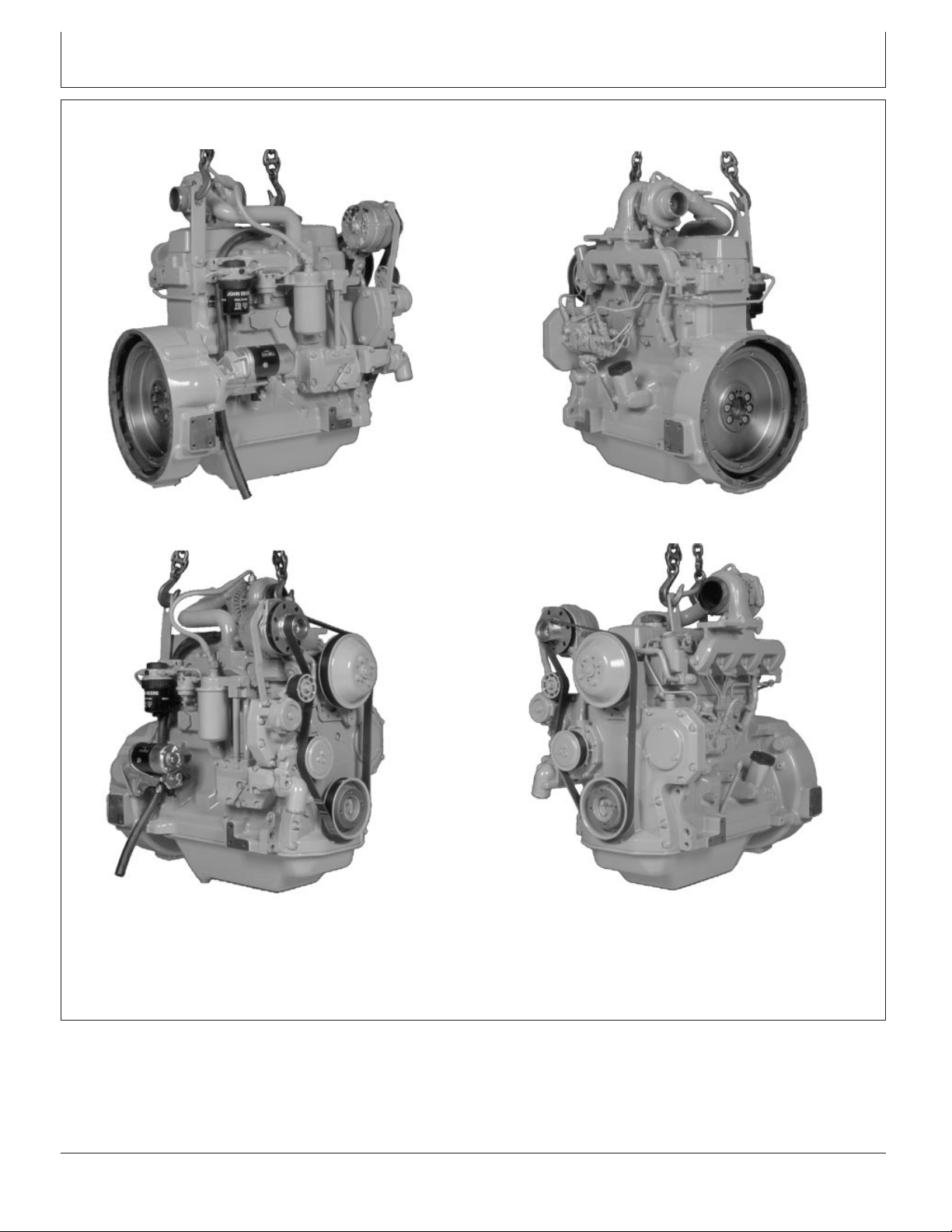
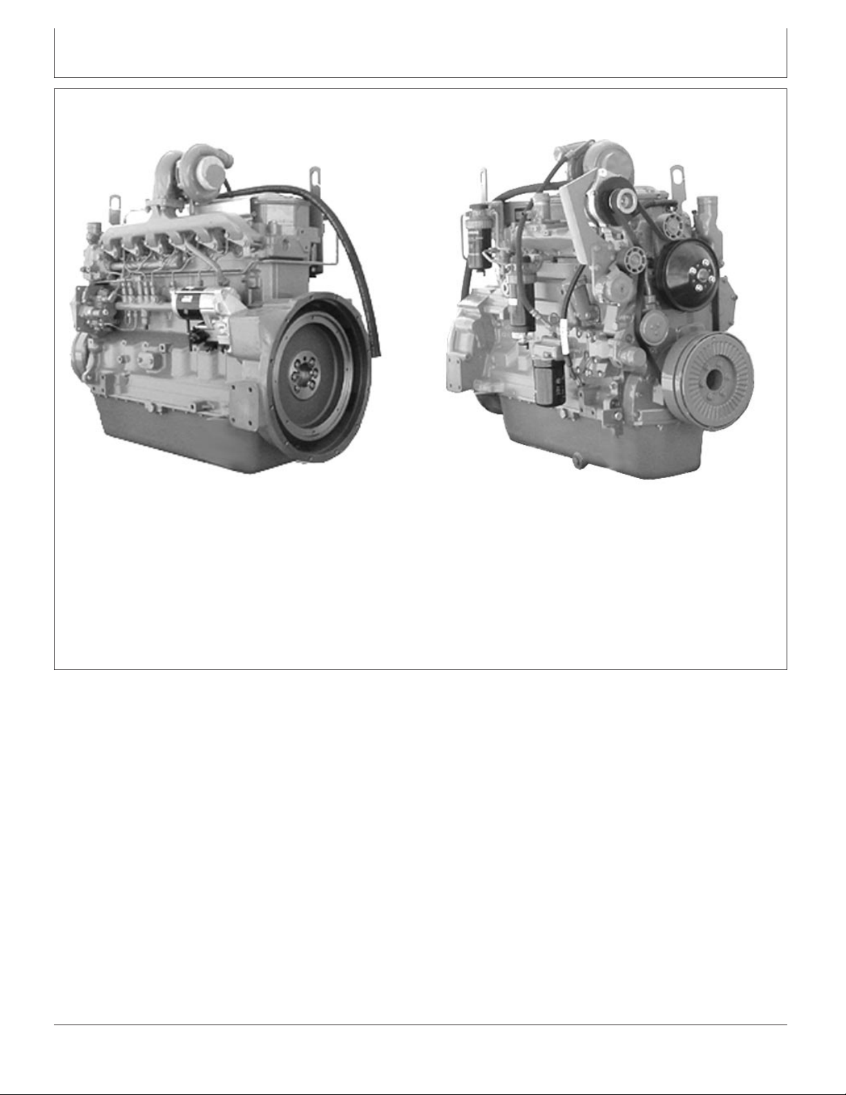
POWERTECH4.5L Engine—Tier 1/Stage I
Introduction
3/4 Right Rear View
3/4 Right Front View
RG7636 –UN–23NOV97
RG7639 –UN–23NOV97
3/4 Left Rear View
RG7638 –UN–23NOV97
RG7637 –UN–23NOV97
3/4 Left Front View
P
OWERTECH
CTM104 (27JAN06) PowerTech Plus 4.5L & 6.8L Diesel Engines
is a registered trademark of Deere & Company
DPSG,OUO1004,129 –19–15MAY02–1/1
013006
PN=5
Page 6
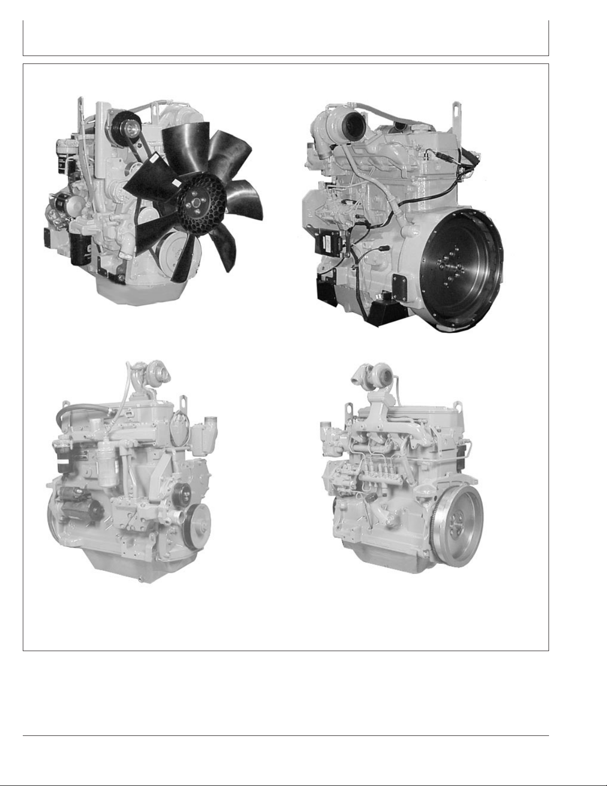
POWERTECH4.5L Engine—Tier 2/Stage II
Introduction
3/4 Right Front View—Two-Valve Head Engine
3/4 Right Front View—Four-Valve Head Engine
RG11932 –UN–06NOV01
RG13617A –UN–18MAY04
3/4 Left Rear View—Two-Valve Head Engine
RG11931 –UN–06NOV01
RG13618A –UN–18MAY04
3/4 Left Rear View—Four-Valve Head Engine
P
OWERTECH
CTM104 (27JAN06) PowerTech Plus 4.5L & 6.8L Diesel Engines
is a registered trademark of Deere & Company
OUO1080,0000238 –19–03JUN04–1/1
013006
PN=6
Page 7
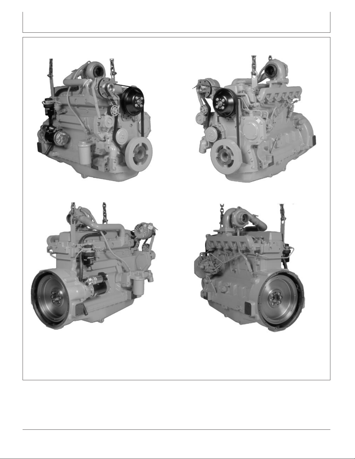
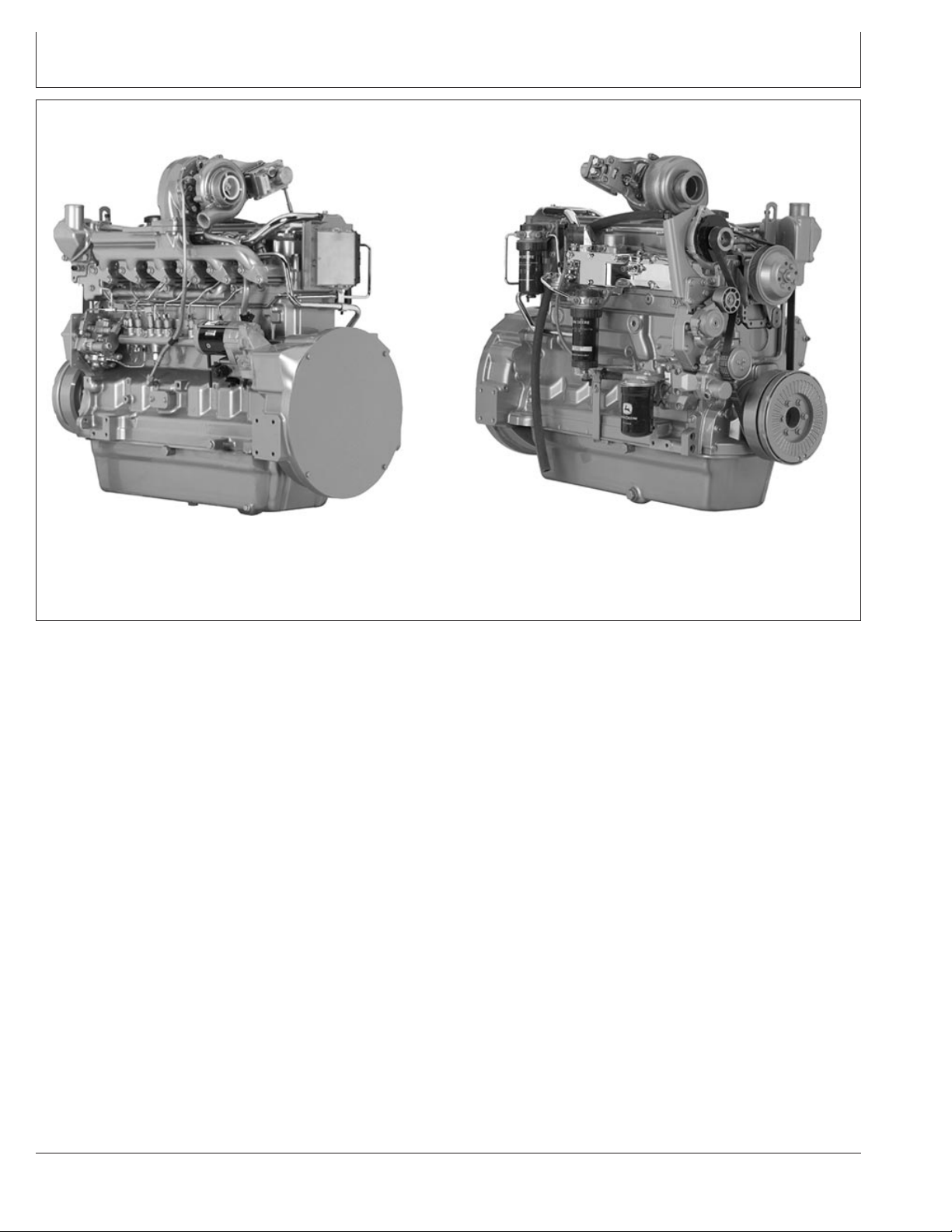
POWERTECH6.8L Engine—Tier 1/Stage I
Introduction
3/4 Right Front View
3/4 Right Rear View
RG7641 –UN–23NOV97
RG7643 –UN–23NOV97
3/4 Left Front View
RG7640 –UN–23NOV97
RG7642 –UN–23NOV97
3/4 Left Rear View
P
OWERTECH
CTM104 (27JAN06) PowerTech Plus 4.5L & 6.8L Diesel Engines
is a registered trademark of Deere & Company
DPSG,OUO1004,130 –19–15MAY02–1/1
013006
PN=7
Page 8
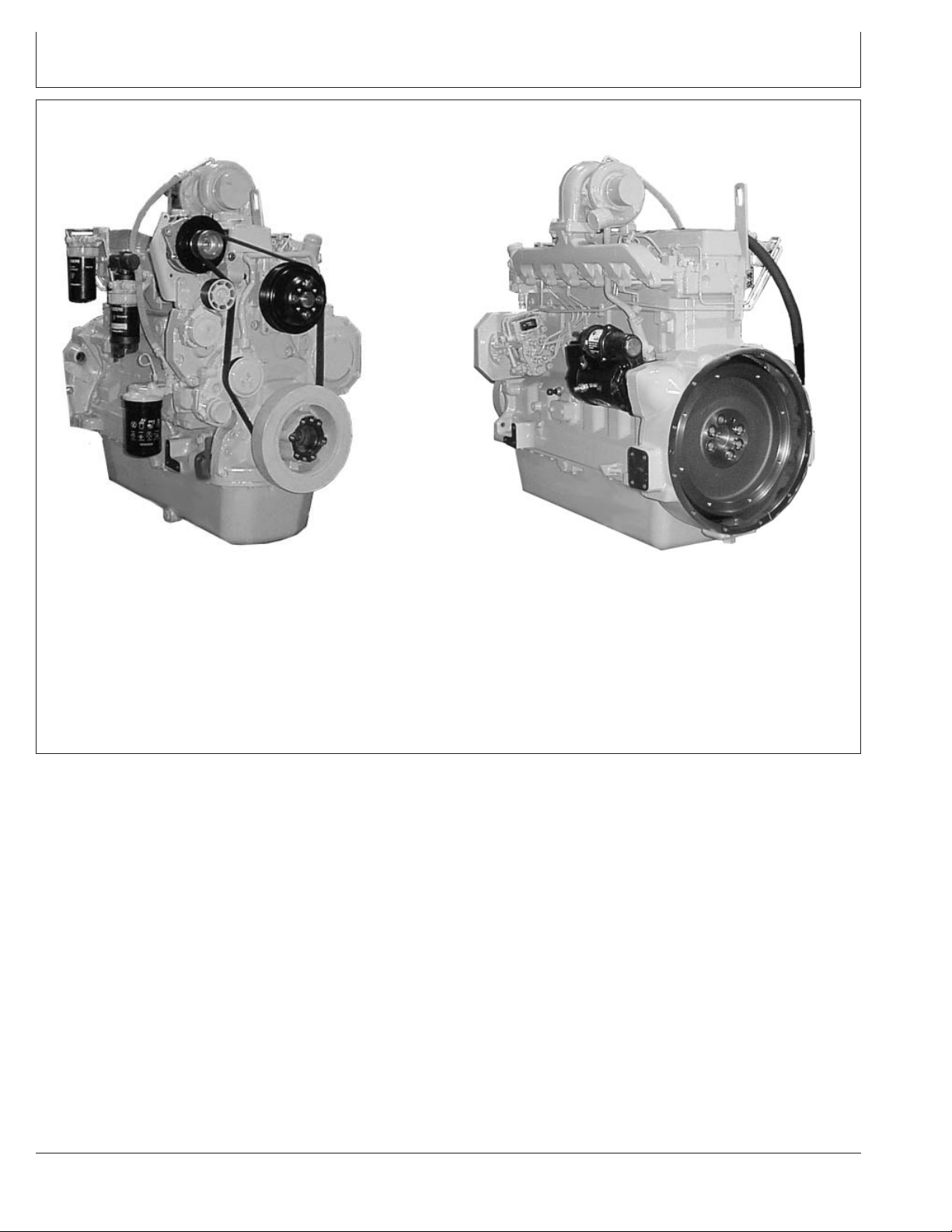
POWERTECH6.8L Engine—Tier 2/Stage II
Introduction
3/4 Right Front View—Two-Valve Head Engine
P
OWERTECH
is a registered trademark of Deere & Company
RG11934 –UN–24OCT01
3/4 Left Rear View—Two-Valve Head Engine
RG11933 –UN–24OCT01
OUO1080,0000239 –19–06JUN02–1/1
CTM104 (27JAN06) PowerTech Plus 4.5L & 6.8L Diesel Engines
013006
PN=8
Page 9
Introduction
POWERTECH6.8L Engine With Electronic Fuel System—Tier 2/Stage II
6068HF475 Four-Valve Engine (Level 11 Electronic Fuel System
with Denso High Pressure Common Rail)
P
OWERTECH
is a registered trademark of Deere & Company
RG12199 –UN–24MAY02
6068HF475 Four-Valve Engine
RG12200 –UN–24MAY02
OUO1083,00005FC –19–21OCT05–1/1
CTM104 (27JAN06) PowerTech Plus 4.5L & 6.8L Diesel Engines
013006
PN=9
Page 10
Introduction
POWERTECH6.8L Engine With Electronic Fuel System—Tier 3/Stage IIIA
6068HF485 Engine Shown (Electronic Fuel System With Denso
High Pressure Common Rail)
P
OWERTECH
is a registered trademark of Deere & Company
RG13547 –UN–11NOV04
6068HF485 Shown
RG13546 –UN–11NOV04
OUO1083,00005FC –19–17DEC03–1/1
CTM104 (27JAN06) PowerTech Plus 4.5L & 6.8L Diesel Engines
013006
PN=10
Page 11

Contents
SECTION 01—General Information
Group 000—Safety
Group 001—Engine Identification and Application
Charts
Group 002—Fuels, Lubricants and Coolants
SECTION 02—Repair and Adjustments
Group 010—Engine Rebuild
Group 020—Cylinder Head and Valves (Two-Valve
Head Engines)
Group 021—Cylinder Head and Valves (Four-Valve
Head Engines)
Group 030—Cylinder Block, Liners, Pistons and
Rods
Group 040—Crankshaft, Main Bearings and
Flywheel
Group 050—Camshaft, Balancer Shafts and Timing
Gear Train
Group 060—Lubrication System
Group 070—Cooling System
Group 080—Air Intake and Exhaust System
Group 090—Fuel System
Group 100—Starting and Charging Systems
01
02
03
04
05
SECTION 03—Theory of Operation
Group 120—Base Engine Operation
SECTION 04—Diagnostics
Group 150—Observable Diagnostics and Tests
SECTION 05—Tools and Other Materials
Group 170—Repair Tools and Other Materials
Group 180—Diagnostic Service Tools
Group 190—Dealer Fabricated Service Tools
SECTION 06—Specifications
Group 200—Repair and General OEM
Specifications
Group 210—Diagnostic Specifications
All information, illustrations and specifications in this manual are based on
the latest information available at the time of publication. The right is
reserved to make changes at any time without notice.
06
INDX
CTM104 (27JAN06)
COPYRIGHT2006
DEERE & COMPANY
Moline, Illinois
A John Deere ILLUSTRUCTIONManual
Copyright1996, 1998, 2000, 2002, 2004, 2005
i
PowerTech Plus 4.5L & 6.8L Diesel Engines
All rights reserved
Previous Editions
013006
PN=1
Page 12

01
02
03
04
05
Contents
06
INDX
CTM104 (27JAN06)
ii
PowerTech Plus 4.5L & 6.8L Diesel Engines
013006
PN=2
Page 13

Page
Group 000—Safety ....................01-000-1
Group 001—Engine Identification and Application
Charts
Engine Serial Number Plate Information .....01-001-1
OEM Engine Option Code Label...........01-001-3
Information Relative to Emissions
Regulations .........................01-001-3
Engine Application Charts................01-001-4
Group 002—Fuels, Lubricants and Coolants
Diesel Fuel ...........................01-002-1
Bio-Diesel Fuel ........................01-002-2
Lubricity of Diesel Fuel ..................01-002-3
Testing Diesel Fuel .....................01-002-3
Diesel Engine Break-In Oil ...............01-002-4
Diesel Engine Oil—Non-Certified and Tier 1
Certified Engines .....................01-002-5
Diesel Engine Oil—Tier 2/Stage II
Certified Engines .....................01-002-6
Diesel Engine Oil —Tier 3/Stage IIIA Certified
Engines ............................01-002-7
OILSCAN, OILSCAN Plus,
COOLSCAN and COOLSCAN PLUS . . .01-002-8
Oil Filters.............................01-002-8
Grease ..............................01-002-9
Diesel Engine Coolant..................01-002-10
Additional Information About Diesel
Engine Coolants and Supplemental Coolant
Additives ..........................01-002-12
Testing Diesel Engine Coolant ...........01-002-13
Supplemental Coolant Additives ..........01-002-14
Operating in Warm Temperature Climates . .01-002-14
Flush and Service Cooling System ........01-002-15
Disposing of Coolant...................01-002-16
01
Section 01
General Information
Contents
CTM104 (27JAN06)
01-1
PowerTech Plus 4.5L & 6.8L Diesel Engines
013006
PN=1
Page 14

01
Contents
CTM104 (27JAN06)
01-2
PowerTech Plus 4.5L & 6.8L Diesel Engines
013006
PN=2
Page 15
Handle Fluids Safely—Avoid Fires
When you work around fuel, do not smoke or work near
heaters or other fire hazards.
Store flammable fluids away from fire hazards. Do not
incinerate or puncture pressurized containers.
Make sure machine is clean of trash, grease, and debris.
Do not store oily rags; they can ignite and burn
spontaneously.
Group 000
Safety
01
000
1
TS227 –UN–23AUG88
DX,FLAME –19–29SEP98–1/1
Handle Starting Fluid Safely
Starting fluid is highly flammable.
Keep all sparks and flame away when using it. Keep
starting fluid away from batteries and cables.
To prevent accidental discharge when storing the
pressurized can, keep the cap on the container, and store
in a cool, protected location.
Do not incinerate or puncture a starting fluid container.
Service Cooling System Safely
Explosive release of fluids from pressurized cooling
system can cause serious burns.
TS1356 –UN–18MAR92
DX,FIRE3 –19–16APR92–1/1
Shut off engine. Only remove filler cap when cool enough
to touch with bare hands. Slowly loosen cap to first stop
to relieve pressure before removing completely.
CTM104 (27JAN06)
01-000-1
DX,RCAP –19–04JUN90–1/1
PowerTech Plus 4.5L & 6.8L Diesel Engines
TS281 –UN–23AUG88
013006
PN=15
Page 16
01
000
Install Fan Guards
2
Rotating cooling system fans can cause serious injury.
Keep fan guards in place at all times during engine
operation. Wear close fitting clothes. Stop engine and be
sure fan is stopped before making adjustments or
connections, or cleaning near the front of the engine.
Safety
Avoid Hot Parts
Avoid skin contact with exhaust manifolds, turbochargers
and mufflers. Keep flammable materials clear of the
turbocharger.
External dry exhaust parts become very hot during
operation. Turbochargers may reach temperatures as high
as 500°C (932°F) under full load, and naturally aspired
exhaust manifolds may reach 600°C (1112°F) under full
load. This may ignite paper, cloth or wooden materials.
Parts on engines that have been at full load and reduced
to no load idle will maintain approximately 150°C (302°F).
Rotating Fan
TS677 –UN–21SEP89
OUO1083,00005FE –19–17DEC03–1/1
TS271 –UN–23AUG88
Hot Surface
Prevent Battery Explosions
Keep sparks, lighted matches, and open flame away from
the top of battery. Battery gas can explode.
Never check battery charge by placing a metal object
across the posts. Use a volt-meter or hydrometer.
Do not charge a frozen battery; it may explode. Warm
battery to 16°C (60°F).
CTM104 (27JAN06)
01-000-2
OUO1083,00005FF –19–22DEC05–1/1
DX,SPARKS –19–03MAR93–1/1
PowerTech Plus 4.5L & 6.8L Diesel Engines
TS204 –UN–23AUG88
013006
PN=16
Page 17
Safety
Prepare for Emergencies
Be prepared if a fire starts.
Keep a first aid kit and fire extinguisher handy.
Keep emergency numbers for doctors, ambulance service,
hospital, and fire department near your telephone.
01
000
3
Handling Batteries Safely
DX,FIRE2 –19–03MAR93–1/1
TS291 –UN–23AUG88
TS204 –UN–23AUG88TS203 –UN–23AUG88
CTM104 (27JAN06)
Continued on next page
01-000-3
DPSG,OUO1004,2758 –19–22DEC05–1/2
PowerTech Plus 4.5L & 6.8L Diesel Engines
013006
PN=17
Page 18

01
000
Safety
4
CAUTION: Battery gas can explode. Keep
sparks and flames away from batteries. Use a
flashlight to check battery electrolyte level.
Never check battery charge by placing a metal
object across the posts. Use a voltmeter or
hydrometer.
Always remove grounded (-) battery clamp first
and replace it last.
Do not charge a frozen battery; it may explode.
Warm battery to 16°C (60°F).
CAUTION: Sulfuric acid in battery electrolyte is
poisonous. It is strong enough to burn skin, eat
holes in clothing, and cause blindness if
splashed into eyes.
Avoid the hazard by:
1. Filling batteries in a well-ventilated area.
2. Wearing eye protection and rubber gloves.
3. Avoiding breathing fumes when electrolyte is
added.
4. Avoiding spilling or dripping electrolyte.
5. Use proper jump start procedure.
If you spill acid on yourself:
1. Flush your skin with water.
2. Apply baking soda or lime to help neutralize
the acid.
3. Flush your eyes with water for 15—30
minutes. Get medical attention immediately.
If acid is swallowed:
1. Do not induce vomiting.
2. Drink large amounts of water or milk, but do
not exceed2L(2quarts).
3. Get medical attention immediately.
WARNING: Battery posts, terminals, and related
accessories contain lead and lead compounds, chemicals
known to the State of California to cause cancer and
reproductive harm. Wash hands after handling.
CTM104 (27JAN06)
01-000-4
DPSG,OUO1004,2758 –19–22DEC05–2/2
PowerTech Plus 4.5L & 6.8L Diesel Engines
013006
PN=18
Page 19
Safety
Avoid High-Pressure Fluids
Escaping fluid under pressure can penetrate the skin
causing serious injury.
Avoid the hazard by relieving pressure before
disconnecting hydraulic or other lines. Tighten all
connections before applying pressure.
Search for leaks with a piece of cardboard. Protect hands
and body from high pressure fluids.
If an accident occurs, see a doctor immediately. Any fluid
injected into the skin must be surgically removed within a
few hours or gangrene may result. Doctors unfamiliar with
this type of injury should reference a knowledgeable
medical source. Such information is available from Deere
& Company Medical Department in Moline, Illinois, U.S.A.
01
000
5
X9811 –UN–23AUG88
Wear Protective Clothing
Wear close fitting clothing and safety equipment
appropriate to the job.
Prolonged exposure to loud noise can cause impairment
or loss of hearing.
Wear a suitable hearing protective device such as
earmuffs or earplugs to protect against objectionable or
uncomfortable loud noises.
Operating equipment safely requires the full attention of
the operator. Do not wear radio or music headphones
while operating machine.
DX,FLUID –19–03MAR93–1/1
TS206 –UN–23AUG88
DX,WEAR –19–10SEP90–1/1
CTM104 (27JAN06)
01-000-5
PowerTech Plus 4.5L & 6.8L Diesel Engines
013006
PN=19
Page 20
01
000
Service Machines Safely
6
Tie long hair behind your head. Do not wear a necktie,
scarf, loose clothing, or necklace when you work near
machine tools or moving parts. If these items were to get
caught, severe injury could result.
Remove rings and other jewelry to prevent electrical
shorts and entanglement in moving parts.
Safety
Work In Ventilated Area
Engine exhaust fumes can cause sickness or death. If it is
necessary to run an engine in an enclosed area, remove
the exhaust fumes from the area with an exhaust pipe
extension.
If you do not have an exhaust pipe extension, open the
doors and get outside air into the area
Work in Clean Area
Before starting a job:
• Clean work area and machine.
• Make sure you have all necessary tools to do your job.
• Have the right parts on hand.
• Read all instructions thoroughly; do not attempt
shortcuts.
DX,LOOSE –19–04JUN90–1/1
TS228 –UN–23AUG88
TS220 –UN–23AUG88
DX,AIR –19–17FEB99–1/1
CTM104 (27JAN06)
01-000-6
DX,CLEAN –19–04JUN90–1/1
PowerTech Plus 4.5L & 6.8L Diesel Engines
T6642EJ –UN–18OCT88
013006
PN=20
Page 21
Safety
Remove Paint Before Welding or Heating
Avoid potentially toxic fumes and dust.
Hazardous fumes can be generated when paint is heated
by welding, soldering, or using a torch.
Remove paint before heating:
• Remove paint a minimum of 100 mm (4 in.) from area
to be affected by heating. If paint cannot be removed,
wear an approved respirator before heating or welding.
• If you sand or grind paint, avoid breathing the dust.
Wear an approved respirator.
• If you use solvent or paint stripper, remove stripper with
soap and water before welding. Remove solvent or
paint stripper containers and other flammable material
from area. Allow fumes to disperse at least 15 minutes
before welding or heating.
Do not use a chlorinated solvent in areas where welding
will take place.
01
000
7
TS220 –UN–23AUG88
Do all work in an area that is well ventilated to carry toxic
fumes and dust away.
Dispose of paint and solvent properly.
Avoid Heating Near Pressurized Fluid Lines
Flammable spray can be generated by heating near
pressurized fluid lines, resulting in severe burns to
yourself and bystanders. Do not heat by welding,
soldering, or using a torch near pressurized fluid lines or
other flammable materials. Pressurized lines can
accidentally burst when heat goes beyond the immediate
flame area.
DX,PAINT –19–24JUL02–1/1
TS953 –UN–15MAY90
DX,TORCH –19–10DEC04–1/1
CTM104 (27JAN06)
01-000-7
PowerTech Plus 4.5L & 6.8L Diesel Engines
013006
PN=21
Page 22
01
000
Illuminate Work Area Safely
8
Illuminate your work area adequately but safely. Use a
portable safety light for working inside or under the
machine. Make sure the bulb is enclosed by a wire cage.
The hot filament of an accidentally broken bulb can ignite
spilled fuel or oil.
Safety
Use Proper Lifting Equipment
Lifting heavy components incorrectly can cause severe
injury or machine damage.
Follow recommended procedure for removal and
installation of components in the manual.
Construct Dealer-Made Tools Safely
Faulty or broken tools can result in serious injury. When
constructing tools, use proper, quality materials and good
workmanship.
Do not weld tools unless you have the proper equipment
and experience to perform the job.
DX,LIGHT –19–04JUN90–1/1
TS223 –UN–23AUG88
TS226 –UN–23AUG88
DX,LIFT –19–04JUN90–1/1
CTM104 (27JAN06)
01-000-8
Construct Dealer-Made Tools Safely
DPSG,OUO1004,899 –19–19MAY99–1/1
PowerTech Plus 4.5L & 6.8L Diesel Engines
LX1016749 –UN–01JUL97
013006
PN=22
Page 23
Safety
Practice Safe Maintenance
Understand service procedure before doing work. Keep
area clean and dry.
Never lubricate, service, or adjust machine while it is
moving. Keep hands, feet , and clothing from
power-driven parts. Disengage all power and operate
controls to relieve pressure. Lower equipment to the
ground. Stop the engine. Remove the key. Allow machine
to cool.
Securely support any machine elements that must be
raised for service work.
Keep all parts in good condition and properly installed. Fix
damage immediately. Replace worn or broken parts.
Remove any buildup of grease, oil, or debris.
On self-propelled equipment, disconnect battery ground
cable (-) before making adjustments on electrical systems
or welding on machine.
01
000
9
On towed implements, disconnect wiring harnesses from
tractor before servicing electrical system components or
welding on machine.
Use Proper Tools
Use tools appropriate to the work. Makeshift tools and
procedures can create safety hazards.
Use power tools only to loosen threaded parts and
fasteners.
For loosening and tightening hardware, use the correct
size tools. DO NOT use U.S. measurement tools on
metric fasteners. Avoid bodily injury caused by slipping
wrenches.
TS218 –UN–23AUG88
DX,SERV –19–17FEB99–1/1
TS779 –UN–08NOV89
Use only service parts meeting John Deere specifications.
CTM104 (27JAN06)
01-000-9
DX,REPAIR –19–17FEB99–1/1
PowerTech Plus 4.5L & 6.8L Diesel Engines
013006
PN=23
Page 24
01
000
Dispose of Waste Properly
10
Improperly disposing of waste can threaten the
environment and ecology. Potentially harmful waste used
with John Deere equipment include such items as oil, fuel,
coolant, brake fluid, filters, and batteries.
Use leakproof containers when draining fluids. Do not use
food or beverage containers that may mislead someone
into drinking from them.
Safety
Do not pour waste onto the ground, down a drain, or into
any water source.
Air conditioning refrigerants escaping into the air can
damage the Earth’s atmosphere. Government regulations
may require a certified air conditioning service center to
recover and recycle used air conditioning refrigerants.
Inquire on the proper way to recycle or dispose of waste
from your local environmental or recycling center, or from
your John Deere dealer.
Live With Safety
Before returning machine to customer, make sure
machine is functioning properly, especially the safety
systems. Install all guards and shields.
TS1133 –UN–26NOV90
DX,DRAIN –19–03MAR93–1/1
CTM104 (27JAN06)
01-000-10
DX,LIVE –19–25SEP92–1/1
PowerTech Plus 4.5L & 6.8L Diesel Engines
TS231 –19–07OCT88
013006
PN=24
Page 25
Engine Identification and Application Charts
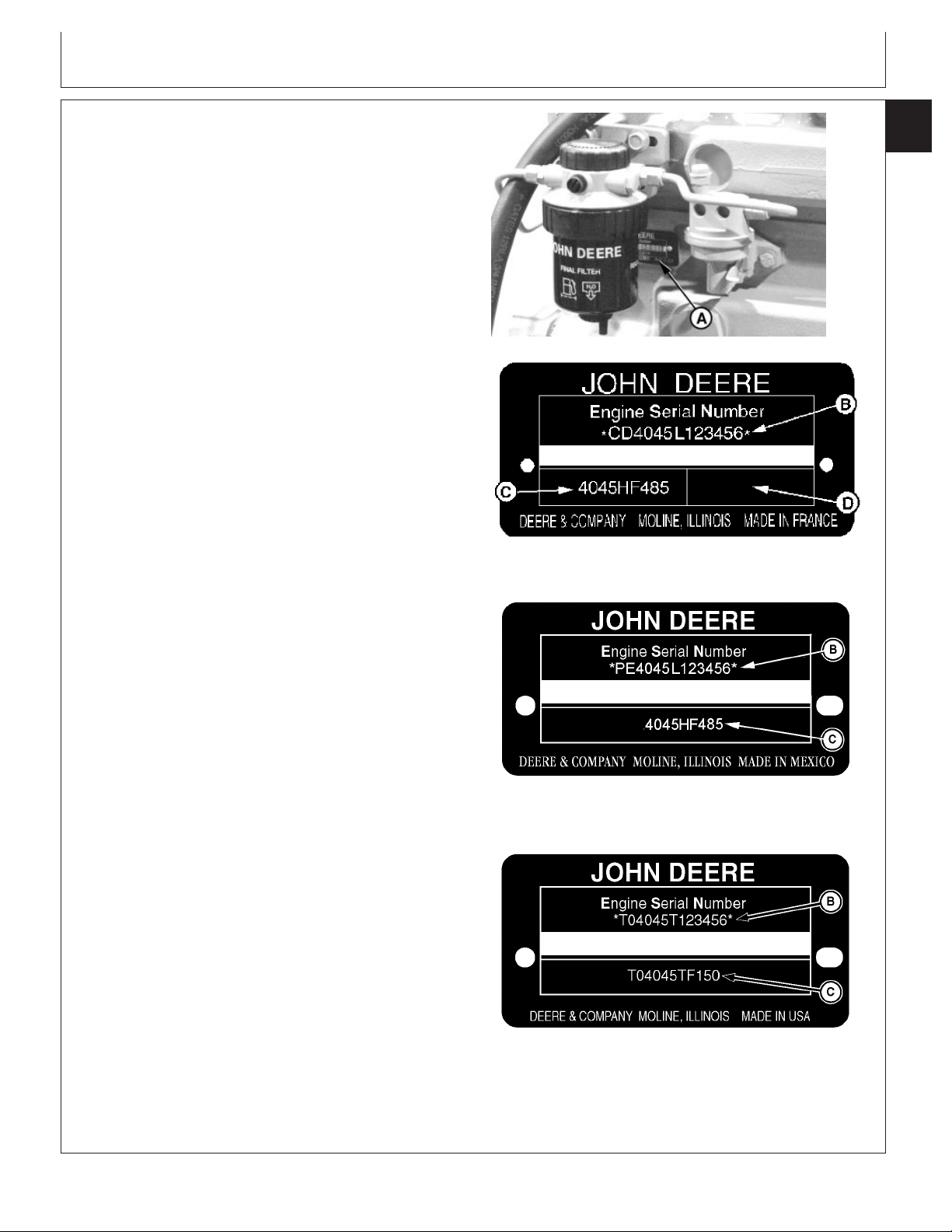
Engine Serial Number Plate Information
IMPORTANT: The engine serial number plate (A) can
be easily destroyed. Before “hot tank”
cleaning the block, remove the plate.
NOTE: Four-valve head engines have “16V” or “24V”
printed on a plate located on the rocker arm
cover. The 4045HF475 model has “16V” to denote
16 valves total while 6068HF475 has “24V” to
denote 24 valves total.
Engine Serial Number (B)
Each engine has a 13-digit John Deere engine serial
number identifying the producing factory, engine model
designation, and a 6-digit sequential number. The
following is an example:
CD4045L123456
CD ...................... Engine Manufacturing Location
CD ............ Saran, France
T0 ............. Dubuque, Iowa
PE ............. Torreon, Mexico
J0 .............. Rosario, Argentina
4 ........................ Number of Cylinders
045 .................... Displacement in Liters ( 4.5 Liters)
L ........................ Aspiration Code (Early Engines) or Emission
Tier Level (Later Engines)
D ............... Naturally aspirated
T ............... Turbocharged, no aftercooling
A ............... Turbocharged and air-to-coolant aftercooled
H ............... Turbocharger and air-to-water aftercooled
S ............... Turbocharged and air-to sea water aftercooled
B ................ Non-certified engine
C,E or F ..... Tier 1/Stage I emission certified engine
G, J or K .... Tier 2/Stage II emission certified engine
L, M, N or P Tier 3/Stage IIIA emission certified engine
123456 ............... 6-digit unique sequence number
Engine Model Designation (C)
Group 001
01
001
1
RG7778 –UN–11NOV97
RG13806 –UN–23JAN06
Saran Serial Number Plate
RG13716 –UN–23JAN06
Torreon Serial Number Plate
The second line of information on the serial number plate
identifies the engine/machine or OEM relationship. See
ENGINE APPLICATION CHARTS later in this group.
A—Engine Serial Number Plate
B—Engine Serial Number
C—Engine Application Data
D—Empty, Coefficient of Absorption or Saran internal
factory identification
CTM104 (27JAN06)
01-001-1
Dubuque Engine Serial Number Plate
Continued on next page
PowerTech Plus 4.5L & 6.8L Diesel Engines
RG9060 –UN–16MAR98
RG19661,0000005 –19–27JAN06–1/2
013006
PN=25
Page 26

Engine Identification and Application Charts
01
001
4045HF485
2
4 ..................................................... Number of Cylinders
045 ................................................. Displacement in Liters ( 4.5 Liters)
H .................................................... Aspiration Code )
F ..................................................... User Code
485 Application Code See Engine Application Charts later in this group
D ...................................... Naturally aspirated
T ....................................... Turbocharged, no aftercooling
A ...................................... Turbocharged and air-to-coolant aftercooled
H ...................................... Turbocharger and air-to-water aftercooled
S ...................................... Turbocharged and air-to sea water aftercooled
AT .................................... Agritalia srl (Vittoria, Sicily, Italy)
BE .................................... Bell Equipment Co. (Richards Bay, South Africa)
CQ ................................... John Deere Brazil (Horizontina, Brazil)
DW ................................... John Deere Davenport Works (Davenport, Iowa)
E ...................................... John Deere Ottumwa Works (Ottumwa, Iowa)
F ....................................... OEM (Original Equipment Manufacturers)
FG .................................... Goldoni S.P.A. (Modena, Italy)
FM .................................... Marine Engine
H ....................................... John Deere Harvester Works (East Moline, Illinois)
KV ..................................... John Deere Commercial Worksite Products (Knoxville, Tennessee/Dubuque, Iowa)
L ........................................ John Deere Werke Mannheim (Germany)
LA ...................................... John Deere Werke Manheim (Germany) (Engines with Bosch VP44 Injection Pump)
LV ...................................... John Deere Commercial Product (Augusta, Georgia)
N ....................................... John Deere Des Moines Works (Des Moines, Iowa)
P ........................................ Industrias John Deere Mexico S.A. de C.V. (Saltillo/Monterrey, Mexico)
PY ..................................... Larson & Toubro Ltd. (Pune, India)
RW .................................... John Deere Waterloo Tractor Works (Waterloo, Iowa)
T ........................................ John Deere Dubuque Works (Dubuque, Iowa)
T8 ...................................... Cameco Industries (Thibodaux, Louisiana)
TJ ...................................... John Deere Forestry (formerly Timberjack) (Sweden/Finland/Canada/USA)
YC ..................................... John Deere Jialian Harvester Co. Limited (China)
Z ........................................ John Deere Werke Zweibrucken (Germany)
Coefficient of Absorption (D) — (Early Saran-Built
Engines - Later Engines, Internal Factory
Identification)
The second line of information on Saran serial number
plate may also contain the coefficient of absorption value
for smoke emissions or, for later engines, an internal
factory identification number.
RG19661,0000005 –19–27JAN06–2/2
CTM104 (27JAN06)
01-001-2
PowerTech Plus 4.5L & 6.8L Diesel Engines
013006
PN=26
Page 27
Engine Identification and Application Charts
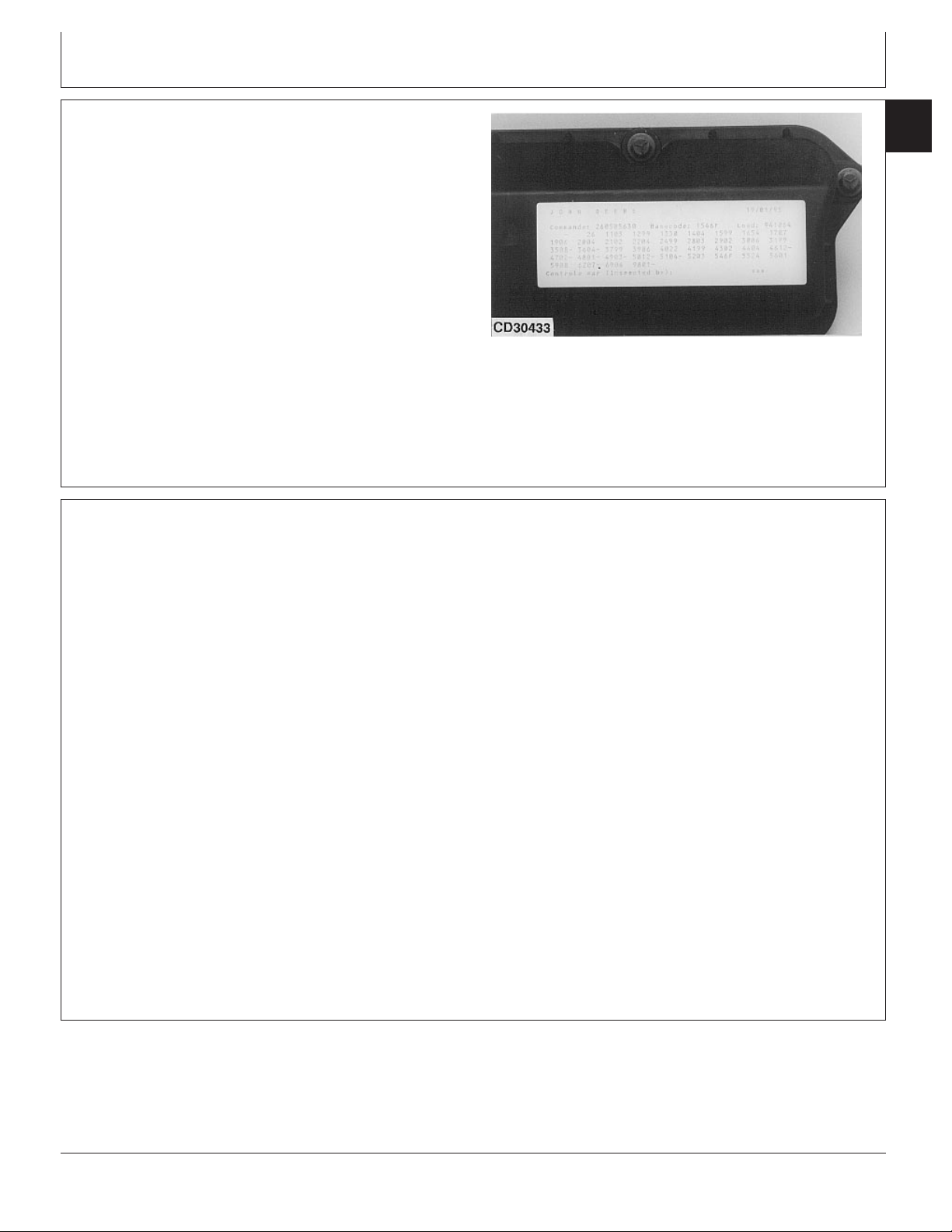
OEM Engine Option Code Label
An option code label is secured to the top of the valve
cover and identifies the factory installed options on each
OEM engine to ensure correct parts acquisition.
Always provide option code information and engine base
code when ordering repair parts. A listing of option codes
is given in Parts Catalogs and Operator’s Manuals.
NOTE: Before “hot tank” cleaning, ensure that option
codes are recorded elsewhere.
Information Relative to Emissions Regulations
01
001
3
CD30433 –UN–10MAY95
DPSG,OUO1004,482 –19–07NOV98–1/1
Depending on the final destination, engines can meet
the emissions regulations according to the US
Environmental Protection Agency (EPA), California Air
Resources Board (CARB) and for Europe, the
Directive 97/68/EC relating the measures against the
emissions of particles and gaseous pollutant from
internal combustion engines. Such engines are called
“CERTIFIED” and receive an emission label on the
engine.
The regulations prohibit tampering with the
emission-related components listed below which would
render that component inoperative or to make any
adjustment on the engine beyond published
specifications. It is also illegal to install a part or
component where the principle effect of that
component is to bypass, defeat, or render inoperative
any engine component or device which would affect
the engine’s conformance to the emission regulations.
To summarize, it is illegal to do anything except
return the engine to its original published
specifications.
List of emission-related components:
• Fuel injection system
• Intake manifold
• Turbocharger
• EGR cooler
• EGR valve
• Charge air cooling system
• Piston
OUO1080,0000035 –19–29AUG01–1/1
CTM104 (27JAN06)
01-001-3
PowerTech Plus 4.5L & 6.8L Diesel Engines
013006
PN=27
Page 28
Engine Identification and Application Charts
01
001
Engine Application Charts
4
JOHN DEERE AGRICULTURAL EQUIPMENT
Machine Model Engine Model
Bell Equipment, South Africa
884 Cane Loader CD4045TBE50 (Tier 1)
904 Haul Tractor CD4045TBE51 (Tier 1)
1266 Haul Tractor CD6068TBE50 (Tier 1)
1866 Haul Tractor CD6068TBE51 (Tier 2)
2256 Haul Tractor CD6068HBE50 (Tier 1)
Des Moines, Iowa
4700 Sprayer (138 kW) T06068TN050, PE6068TN050, T06068TN053, PE6068TN053
4700 Sprayer (149 kW) PE6068TN052
4710 Sprayer PE6068TN052
4720 Sprayer PE6068HN051 (Tier 2)
6700 Sprayer T04045TN050, PE4045TN050
7455 Cotton Stripper T06068TN051, PE6068TN051
7460 Cotton Stripper PE6068TN054
9935 Cotton Picker T06068TN051, PE6068TN051
9970 Cotton Picker PE6068HN052 (Tier 2)
East Moline, Illinois
9400 Combine T06068HH050
9410 Combine T06068HH051
9450 Combine T06068HH052, PE6068HH052
9550 Combine (Low Power) PE6068HH054 (4-Valve) (Tier 2)
9550/9550SH Combine (High Power) PE6068HH055 (4-Valve) (Tier 2)
9560 Combine (Low Power) PE6068HH054 (4-Valve) (Tier 2)
9560 Combine (High Power) PE6068HH055 (4-Valve) (Tier 2)
9965 Peanut Combine PE6068HH057
Horizontina, Brazil
1165 Combine J06068TCQ11
1170 Combine CD6068TCQ50
1175 Combine J06068TCQ12
1450 Combine J06068TCQ04
1450 CWS/WTS Combine CD6068HCQ60, JO6068TCG04(Tier 2)
1550 CWS/WTS Combine CD6068HCQ61, JO6068ACQ04(Tier 2)
3518 Combine J06068TYC51
9650 Combine J06068HCQ01
5403/5605 Tractor J04045DCQ01
5705 Tractor J04045TCQ02
6405 Tractor J04045TCQ01
PE6068HH058 (4-Valve) Tier 3)
CTM104 (27JAN06)
Continued on next page
01-001-4
RG19661,0000008 –19–25JAN06–1/16
PowerTech Plus 4.5L & 6.8L Diesel Engines
013006
PN=28
Page 29
Engine Identification and Application Charts
JOHN DEERE AGRICULTURAL EQUIPMENT
Machine Model Engine Model
6415 Tractor J04045TCQ03
6605 Tractor J06068TCQ02
6615 Tractor J06068TCQ15
7505 Tractor J06068TCQ03
7515 Tractor J06068TCQ14
Jiamusi, China
1075 Combine CD6068TYC50, J06068TYC50
3518 Combine CD6068TYC51, CD6068HYC50, J06068TYC51
Zweibrucken, Germany
2254 Combine CD6068HZ050
3200/3400 Telehandler CD4045TZ250
3215/3415 Telehandler (European Version) CD4045HZ275, CD4045TZ270
3215/3415 Telehandler (North American Version) CD4045HZ275, CD4045TZ270
3220/3420 Telehandler (European Version) CD4045HZ275
3220/3420 Telehandler (North American Version) CD4045HZ275
3800 Telehandler, Articulated CD4045HZ050, 4045HZ060
9540/9540 Hillmaster Combine CD6068HZ060
CD6068HZ480 (4-Valve) (Tier 3)
9560/9560HM Combine CD6068HZ470 (4-Valve) (Tier 2)
CD6068HZ481 (4-Valve) (Tier 3)
Ottumwa, Iowa
4890 Windrower T04045TE050, PE4045TE050
4895 Windrower T04045TE051, PE4045TE051
4990 Windrower T06068TE050, PE6068TE050
4995 Windrower PE6068TE051
Waterloo, Iowa
7210 (SYNCROPLUS) Tractor T06068TRW53
7210 (POWRQUAD) Tractor T06068TRW50, PE6068TRW50
7220 Tractor CD6068TRW01, PE6068TRW01, PE6068HRW59
7220 IVT Tractor PE6068HRW61
7320 Tractor CD6068HRW01, PE6068HRW01, PE6068HRW59
7320 IVT Tractor PE6068HRW61
7410 (SYNCROPLUS) Tractor T06068TRW54, PE6068HRW54
7410 (POWRQUAD) Tractor T06068TRW51, PE6068TRW51
7420 Tractor CD6068HRW01, PE6068HRW01
7510 (POWRQUAD) Tractor T06068TRW70, PE6068TRW70
7520 Tractor CD6068HRW01, PE6068HRW01
7610 Tractor (105 kW) T06068TRW52, PE6068TRW52
01
001
5
SYNCROPLUS is a trademark of Deere & Company
POWRQUAD is a trademark of Deere & Company
CTM104 (27JAN06)
Continued on next page
01-001-5
RG19661,0000008 –19–25JAN06–2/16
PowerTech Plus 4.5L & 6.8L Diesel Engines
013006
PN=29
Page 30

Engine Identification and Application Charts
01
001
6
Machine Model Engine Model
7610 Tractor (110 kW) T06068TRW72, PE6068TRW72
7720 Tractor (Auxilliary Drive) PE6068HRW54 (4-Valve) (Tier 2)
7810 Tractor (Export-Brazil) PE6068TRW73
7815 Tractor (Export-Brazil) PE6068HRW63
7820 Tractor (Non-Auxilliary Drive) PE6068HRW54 (4-Valve) (Tier 2)
Mannheim, Germany (European Market)
3210 Tractor CD4045DRT50
3310 Tractor CD4045DRT51
3410 Tractor CD4045TRT50
5620 Tractor CD4045DL270
5720 Tractor CD4045TL273
5820 Tractor CD4045TL274
6010 Tractor CD4045DL050
6020 Tractor CD4045DL070
6020SE Tractor CD4045TL270 (Tier 2)
6110 Tractor (Direct Fan Drive) CD4045TL058
6110 Tractor (Viscous Fan Drive) CD4045TL050
6120 Tractor CD4045TL070
6120 Tractor (Premium) CD4045TL271
6120SE Tractor CD4045TL271
6205 Tractor CD4045TL064
6210 Tractor (Direct Fan Drive) CD4045TL059
6210 Tractor (Viscous Fan Drive) CD4045TL051
6215 Tractor (Classic) CD4045TL072
6215 Tractor (Classic) CD4045TL071
6215 Tractor (Classic) CD4045TL272 (Tier 2)
6220 Tractor CD4045TL071
6220 Tractor (Premium) CD4045TL272 (Tier 2)
6220SE Tractor CD4045TL272
6310 Tractor (Direct Fan Drive) CD4045TL060
6310 Tractor (Viscous Fan Drive) CD4045TL052
6310 Tractor (ECU Level 4) CD4045TLA50
6320 Tractor CD4045HL072
6320 IVT Tractor CD4045HLA70
6320 Tractor (Premium) CD4045HL472
6320SE Tractor CD4045TL073, CD4045HL270 (Tier 2)
6410 Tractor (Direct Fan Drive) CD4045TL061
6410 Tractor (Viscous Fan Drive) CD4045TL053
6410 Tractor (ECU Level 4) CD4045TLA51
JOHN DEERE AGRICULTURAL EQUIPMENT
CTM104 (27JAN06)
Continued on next page
01-001-6
RG19661,0000008 –19–25JAN06–3/16
PowerTech Plus 4.5L & 6.8L Diesel Engines
013006
PN=30
Page 31

Engine Identification and Application Charts
JOHN DEERE AGRICULTURAL EQUIPMENT
Machine Model Engine Model
6420 Tractor CD4045HL070
6420 IVT Tractor CD4045HLA72
6420 Tractor (Premium) CD4045HL473 (Tier 2)
6420S Tractor CD4045HLA73 (Tier 2)
6420SE Tractor CD4045HL271 (Tier 2)
6505 Tractor CD6068DL051
6510 Tractor CD6068DL050
6515 Tractor (Classic) (77 kW) CD6068DL071
6515 Tractor (Classic) (85 kW) CD6068DL070
6515 Tractor (Classic) CD6068HL270 (Tier 2)
6520 Tractor CD6068DL070
6520SE Tractor CD6068TL073
6520 Tractor (Premium) CD6068HL470 (4-Valve) (Tier 2), CD6068HL475 (4-Valve) (Tier 2)
6610 Tractor CD6068TL050
6610 Tractor (ECU Level 4) CD6068TLA50
6620 Tractor CD6068HLA70
6620 Tractor (Premium) CD6068HL471
6620SE2 Tractor CD6068HL272
6810 Tractor CD6068TL051
6810 Tractor (ECU Level 4) CD6068TLA51
6820 Tractor CD6068HLA71
6820 Tractor (Premium) CD6068HL472 (4-Valve) (Tier 2)
6910 Tractor (99 kW) CD6068TL052
6910 Tractor (107 kW) CD6068TL054
6910 Tractor (107 kW) (ECU Level 4) CD6068TLA52
6910S Tractor (ECU Level 4) CD6068TLA53
6920 Tractor CD6068HLA72
6920 Tractor (Premium) CD6068HL473 (4-Valve) (Tier 2)
6920S Tractor CD6068HLA73, CD6068HL474 (4-Valve) (Tier 2)
Mannheim, Germany (North American Market)
6110/6110L Tractor CD4045TL063
6120 Tractor CD4045TL070
6120/6120L Tractor CD4045TL271 (Tier 2)
6210/6210L Tractor CD4045TL054
6215 Tractor (Advantage) CD4045TL071 (Tier 1), CD4045TL272 (Tier 2)
6220 Tractor CD4045TL071
6220S Tractor CD4045TL272 (Tier 2)
6310/6310L/6310S Tractor CD4045TL055
6320 Tractor CD4045TL074, CD4045HL073
01
001
7
CTM104 (27JAN06)
Continued on next page
01-001-7
RG19661,0000008 –19–25JAN06–4/16
PowerTech Plus 4.5L & 6.8L Diesel Engines
013006
PN=31
Page 32

Engine Identification and Application Charts
01
001
8
Machine Model Engine Model
6320 IVT Tractor CD4045HLA71, CD4045HL472
6320 IVT Tractor CD4045HL476 (Tier 2)
6320/6320L/S Tractor CD4045HL470, CD4045HL472, CD4045HL270 (Tier 2)
6403, 6405 Tractor (Advantage) CD4045TL062
6410/6410L/6410S Tractor CD4045TL056
6415 Tractor (Advantage) CD4045TL075, CD4045HL272 (Tier 2)
6420 Tractor CD4045HL070
6420 IVT Tractor CD4045HLA72
6420/6420L/S Tractor CD4045HL271 (Tier 2)
6420 IVT Tractor CD4045HL473 (Tier 2)
6510L/6510S Tractor CD4045TL057
6520 Tractor CD4045HL071
6520L/S Tractor CD4045HL273 (Tier 2)
6603 Tractor (Advantage) CD6068TL053
6605 Tractor (Advantage) CD6068TL053
6615 Tractor (Advantage) CD6068TL071
6615 Tractor (Advantage) CD6068HL271 (Tier 2)
6715 Tractor (Advantage) CD6068TL072
6715 Tractor (Advantage) CD6068HL273 (Tier 2)
Saltillo/Monterrey, Mexico
5415 Tractor PE4045DP052
5615 Tractor PE4045DP053
5615 Tractor (Export-Turkey) PE4045DLV51 (Tier 1), PE4045DP054 (Tier 1)
5715 Tractor PE4045TP059
5715 Tractor (Export-Turkey) PE4045TLV51 (Tier 1), PE4045TP062 (Tier 1)
6103 Tractor PE4045TP055
6203 Tractor PE4045TP056
6400 Tractor PE4045TP054
6403 Tractor PE4045TP057 (Non-Certified)
6403 Tractor (Export-U.S.A.) PE4045TP060 (Tier 1)
6415 Tractor PE4045TP061 (Tier 2)
6603 Tractor PE6068TP053 (Non-Certified)
6603 Tractor (Export-U.S.A.) PE6068TP054 (Tier 1)
7220 Tractor PE6068TP055
7320 Tractor PE6068TP056 (Tier 2)
7405 Tractor (Advantage) CD6068TP051, PE6068TP051
JOHN DEERE AGRICULTURAL EQUIPMENT
PE4045TP063 (Non-Certified)
PE4045TP064 (Tier 1)
PE6068TP061 (Non-Certified)
PE6068TP062 (Tier 2)
CTM104 (27JAN06)
Continued on next page
01-001-8
RG19661,0000008 –19–25JAN06–5/16
PowerTech Plus 4.5L & 6.8L Diesel Engines
013006
PN=32
Page 33

Engine Identification and Application Charts
JOHN DEERE AGRICULTURAL EQUIPMENT
Machine Model Engine Model
7410 Tractor CD6068TP052
7420 Tractor PE6068TP057 (Tier 2)
7500 Tractor PE6068TP052
7520 Tractor PE6068TP058 (Tier 2)
Tekirdag, Turkey
5615 Tractor CD4045DTK20, PE4045DP054 (Tier 1)
5715 Tractor PE4045TP062
Thibodaux, Louisiana (Cameco Industries) (Deere)
S30 Harvester PE6068DT850
SP1800 Cane Loader PE6068DT850
SP1850 Cane Loader PE4045TF150, PE4045TT852
SP2252 Cane Loader PE6068TT850
SP3000 Cane Loader PE6068DT850
100 Loader/ Harvester (Kanaf) PE6068TT850
110 Cane Tractor PE4045TT851
215 4WD Tractor PE6068DT850
220 Tractor PE6068TT851
220 4WD Tractor/Pineapple Harvester/Sprayer PE6068TT850, PE6068DT850
404 Vegetable Sprayer T04045TT850, T04045TT801, PE4045TT850
01
001
9
CTM104 (27JAN06)
Continued on next page
01-001-9
RG19661,0000008 –19–25JAN06–6/16
PowerTech Plus 4.5L & 6.8L Diesel Engines
013006
PN=33
Page 34

Engine Identification and Application Charts
01
001
10
Augusta, Georgia
5410 Tractor CD4045DLV50, PE4045DLV50
5410 Tractor (No Engine Air Heater Option) PE4045DLV51
5420/5420N Tractor PE4045DLV50
5420/5420N Tractor (No Engine Air Heater Option) PE4045DLV51
5425 Tractor PE4045TLV53
5510/5510N Tractor CD4045TLV50, PE4045TLV50
5510/5510N Tractor (No Engine Air Heater Option) PE4045TLV51
5510 Tractor (LUK Clutch Option) PE4045TLV52
5520/5520N Tractor PE4045TLV50
5520/5520N Tractor (No Engine Air Heater Option) PE4045TLV51
5520 Tractor PE4045TLV52
5525 Tractor PE4045TLV54
Agritalia srl (Vittoria, Sicily, Italy)
5410 Tractor CD4045TAT50
5415 Tractor CD4045DAT70
5510 Tractor CD4045TAT50
5515 Tractor CD4045TAT70
5615 Tractor CD4045TAT71
JOHN DEERE COMMERCIAL AND CONSUMER EQUIPMENT
CTM104 (27JAN06)
Continued on next page
01-001-10
RG19661,0000008 –19–25JAN06–7/16
PowerTech Plus 4.5L & 6.8L Diesel Engines
013006
PN=34
Page 35

Engine Identification and Application Charts
JOHN DEERE CONSTRUCTION AND FORESTRY EQUIPMENT
Machine Model Engine Model
Backhoe, Loader
310E Backhoe Loader T04045DT055, T04045TT056
310E Backhoe Loader (Alt Comp) T04045TT056
310SE Backhoe Loader T04045TT050
310G Backhoe Loader ( S.N. —910005) T04045DT056, PE4045DT056
310G Backhoe Loader (S.N.—910006) T04045DT058, PE4045TT058 (Tier 2)
310G Backhoe Loader (Alt Comp) (S.N. —910007) T04045TT080, PE4045TT080 (Tier 1)
310G Backhoe Loader (Alt Comp) (S.N. 910057— ) PE4045TT088 (Tier 2)
310J AC Backhoe Loader PE4045TT094 (Tier 2)
310J Backhoe Loader PE4045TT094 (Tier 2)
310J SJ-EH Backhoe Loader PE4045TT094 (Tier 2)
310SG Backhoe Loader (Alt Comp) (S.N. 909514— ) T04045TT080
310SG Backhoe Loader ( S.N. —910004) T04045TT081, PE4045TT081 (Tier 1)
310SG Backhoe Loader (S.N. 910056— ) PE4045TT089 (Tier 2), PE4045HT054 (Tier 3)
315SE Backhoe Loader T04045TT060
315SG Backhoe Loader ( S.N. —909995) T04045TT081, PE4045TT081
315SG Backhoe Loader (S.N. 910069— ) PE4045TT089 (Tier 2)
410E Backhoe Loader T04045TT053
410G Backhoe Loader T04045TT082, PE4045TT082,
PE4045TT093 (Tier 2) PE4045HT055 (Tier 3)
410J Backhoe Loader PE404TT095 (Tier 2)
710D Backhoe Loader (S.N. —834729) T06068TT050, PE6068TT050
710D Backhoe Loader (S.N. 834730— ) T06068TT055, PE6068TT055
710G Backhoe Loader T06068TT057, PE6068TT057
710J Backhoe Loader PE4045TT061 (Tier 2)
710J EH Backhoe Loader PE6068TT061 (Tier 2)
Crawler Dozer, Crawler Loader
DX75 Crawler Dozer (Japan) T04045DT006, T04045DT052
DX75 HST Crawler Dozer (Japan) T04045TT070, PE4045TT070
450G Crawler Dozer (Direct Drive) (S.N. 840528—840890) T04045DT004, T04045TT005 (Non Certified)
450G Crawler Dozer (Direct Drive) (S.N.841246—879425) T04045TT061, PE4045TT061 (Tier 1)
450G Crawler Dozer (Torque Converter) (S.N. 840529— ) T04045TT013 (Non Certified)
450G Crawler Dozer (Torque Converter) T04045TT067, PE4045TT067
450H, 450HLT Crawler Dozer T04045DT053
450H Crawler Dozer (Nat. Asp.) T04045DT057, PE4045DT057 (Tier 2)
450H LGP Crawler Dozer T04045TT058, PE4045TT058
450H LGP Crawler Dozer T04045TT085, PE4045TT085, PE4045TT090 (Tier 2)
450H Crawler Dozer (Alt Comp) T04045TT057, PE4045TT057
450H Crawler Dozer (Alt Comp) T04045TT084, PE4045TT084, PE4045TT090 (Tier 2)
01
001
11
CTM104 (27JAN06)
Continued on next page
01-001-11
RG19661,0000008 –19–25JAN06–8/16
PowerTech Plus 4.5L & 6.8L Diesel Engines
013006
PN=35
Page 36

Engine Identification and Application Charts
01
001
12
Machine Model Engine Model
455G Crawler Loader (Direct Drive) T04045TT061, PE4045TT061 (Tier 1)
455G (Torque Converter) Crawler Loader T04045TT067, PE4045TT067
550G Crawler Dozer T04045TT006, T04045TT014, T04045TT062
550G Crawler Dozer (Torque Converter) T04045TT062, T04045TT068
550H Crawler Dozer (S.N. —909830) T04045TT064, PE4045TT064
550H Crawler Dozer (S.N. 910019— ) PE4045TT086, PE4045TT090 (Tier 2)
550H Forest Fire Plow (S.N.898487—909788) T04045TT083, PE4045TT083
550H LGP Crawler Dozer (S.N. —909667) T04045TT065, PE4045TT065
550H LGP Crawler Dozer (S.N. 910017— ) PE4045TT087, PE4045TT090 (Tier 2)
555G Crawler Loader (Direct Drive) (S.N. 840461— ) T04045TT063, PE4045TT063
555G Crawler Loader (Torque Converter) T04045TT069, PE4045TT069
650G Crawler Dozer (Direct Drive) T04045TT007, T04045TT063, PE4045TT063
650G Crawler Dozer (Torque Converter) T04045TT015, T04045TT063, PE4045TT063, T04045TT069,
650H Crawler Dozer T04045TT066, PE4045TT066
650H Crawler Dozer PE4045HT050 (Tier 2)
650H Forest Fire Plow—71 kw (95 hp) PE4045HT051 (Tier 2)
650H Forest Fire Plow—85 kW (114 hp) T04045TT091, PE4045TT091
700H Crawler Dozer T06068TT056, PE6068TT056
700H Crawler Dozer PE6068TT060 (Tier 2)
750C Crawler Dozer (S.N.—831315) T06068TT007
750C Crawler Dozer (S.N. 831316— ) T06068TT052, PE6068TT052
690D Excavator T06068TT051, PE6068TT051
690ELC Excavator (S.N. 559603— ) T06068TDW56
110 Excavator T04045TT054, PE4045TP052
110C Excavator PE4045TP058
110CFX Excavator PE4045TP058
HYEX Military Excavator PE4045TT050
120 Excavator T04045TT052, PE4045TP051
120C Excavator PE4045HP050 (Tier 2)
160CLC Excavator PE4045HP051 (Tier 2)
160LC Excavator T04045TT055, PE4045TP053
200LC Excavator T06068TT051, PE6068TT051
200CLC Excavator PE6068HT053, PE6068HT059 (Tier 2)
230LC, 230LR Excavator T06068HT051, PE6068HT051
230CLC Excavator PE6068HT054 (Tier 2)
240 Excavator PE6068HT061 (Tier 3)
240DLC Excavator PE6068HT061 (Tier 3)
JOHN DEERE CONSTRUCTION AND FORESTRY EQUIPMENT
PE4045TT069
Excavator
CTM104 (27JAN06)
Continued on next page
01-001-12
RG19661,0000008 –19–25JAN06–9/16
PowerTech Plus 4.5L & 6.8L Diesel Engines
013006
PN=36
Page 37

Engine Identification and Application Charts
JOHN DEERE CONSTRUCTION AND FORESTRY EQUIPMENT
Machine Model Engine Model
270CLC Excavator PE6068HT055 (Tier 2)
270LC Excavator T06068HT052, PE6068HT052
270 Excavator PE6068HT062 (Tier 3)
790ELC Excavator T06068TT005
CFX270CLC Excavator PE6068HT055 (Tier 2)
CFX270LC Excavator T06068HT052, PE6068HT052
Feller Buncher
643G Feller Buncher T06068TT053, PE6068TT053
643H Feller Buncher PE6068TT058
643J Feller Buncher PE6068HTJ55 (4-Valve) (Tier 2)
653E Feller Buncher T06068TT053, PE6068TT053
653G Feller Buncher—120 kW (160 hp) T06068TT053, PE6068TT053, PE6068TT059
653G Feller Buncher—140 kW (188 hp) PE6068HT057
843G Feller Buncher T06068HT050, PE6068HT050
843H Feller Buncher PE6068HT056
843J Feller Buncher PE6068HT056, PE6068HTJ54 (Tier 2)
Forklift
485E, 486E, 488E Forklift T04045DT050, PE4045DT050
Forwarder
810 Forwarder CD4045HTJ75
1010D Forwarder CD4045HTJ76
1110D Forwarder CD6068HTJ75
1410D Forwarder CD6068HTJ77
Grader
670C, 670C Series II Grader T06068HDW53, PE6068HDW53
670CH, 672CH Grader T06068HDW55, PE6068HDW55
670CH Series II, 672CH Series II Grader (S.N. —589368) T06068HDW58, PE6068HDW58
670CH Series II, 672CH Series II Grader (S.N. 589369— ) PE6068HDW61 (Tier 2)
670D Grader PE6068HDW61 (Tier 2)
672D Grader PE6068HDW68 (Tier 3)
Harvester, Wheeled
770D Wheel Harvester CD4045HTJ77
1070D Wheel Harvester CD6068HTJ76
Landscape Loader
210LE Landscape Loader T04045DT050, PE4045DT050, PE4045DT059 (Tier 2), PE4045TT092
(Tier 2)
Log Loader, Knuckleboom
330, 330B, 430, 430B PE6068TTJ50
Knuckleboom Log Loader
01
001
13
CTM104 (27JAN06)
Continued on next page
01-001-13
RG19661,0000008 –19–25JAN06–10/16
PowerTech Plus 4.5L & 6.8L Diesel Engines
013006
PN=37
Page 38

Engine Identification and Application Charts
01
001
14
Machine Model Engine Model
335B, 335C, 435B, 435C, 437C PE6068TTJ51
Knuckleboom Log Loader
2054 Logger PE6068HT053, PE6068TT053, PE6068HT059 PE6068HT065 (Tier 2)
2554 Logger PE6068HT054, PE6068HT064 (Tier 2)
LX80 Loader T04045HDW51
LX100 Loader (Hitachi Construction Machine) T06068TDW53, PE6068TDW53
LX100-3 Loader (Hitachi Construction Machine) T06068TDW50, PE6068TDW50
LX120 Loader (Hitachi Construction Machine) T06068HDW52, T06068HDW70, PE6068HDW70
324H Loader CD4045DF153
344H Loader T04045TF152, PE4045TF152
344H Loader T04045TF273, CD4045TF273 (Tier 2)
TC44H Tool Carrier T04045TDW50, PE4045TDW50
444H Loader T04045TDW50, T04045HDW50, PE4045TDW50
444J Loader PE4045HDW52 (Tier 2), PE4045HDW53 (Tier 3)
TC54H Tool Carrier T06068TDW50, PE6068TDW50
544H Loader T06068TDW50, PE6068TDW50
544J Loader PE6068HDW56 (Tier 2), PE4045HDW63 (Tier 3)
TC62H Tool Carrier T06068HDW50, PE6068HDW50
624G Loader T06068TDW010
624H Loader T06068HDW50, PE6068HDW50
624J Loader PE6068HDW57 (Tier 2), PE6068HDW67 (Tier 3)
644 Loader PE6068HDW69 (Tier 3)
1204C Loader (Bell Equipment) CD4045TBE52 (Tier 2)
1706C Loader (Bell Equipment) CD6068TBE53 (Tier 1)
1806C Loader CD6068TBE52 (Tier 2)
JD7 Skid Steer Loader PE4045DKV50, PE4045DKV51
270 Skid Steer Loader (Auxiliary Drive) PE4045DKV50
270 Skid Steer Loader (Non-Auxiliary Drive) PE4045DKV51
280 Skid Steer Loader PE4045TKV50
360D Skidder (Timberjack) T06068TDW54, PE6068TDW54
360D Skidder (Timberjack) (S.N. 589337— ) PE6068TDW58 (Tier 2)
460D Skidder (Direct Drive) (Timberjack) T06068TDW55, PE6068TDW55
460D Skidder (Direct Drive) (Timberjack) (S.N. 589337— ) PE6068HDW60 (Tier 2), PE6068HDW65 (Tier 3)
460D Skidder (Torque Converter) (Timberjack) (S.N. —586336) T06068TDW57, PE6068TDW57
460D Skidder (Torque Converter) (Timberjack) (S.N. 589337— ) PE6068HDW59 (Tier 2)
JOHN DEERE CONSTRUCTION AND FORESTRY EQUIPMENT
Loggers
Loader, Four Wheel Drive
Skid Steer Loader
Skidder
CTM104 (27JAN06)
Continued on next page
01-001-14
RG19661,0000008 –19–25JAN06–11/16
PowerTech Plus 4.5L & 6.8L Diesel Engines
013006
PN=38
Page 39

Engine Identification and Application Charts
JOHN DEERE CONSTRUCTION AND FORESTRY EQUIPMENT
Machine Model Engine Model
460D Skidder (Torque Converter) (Timberjack) (Europe) PE6068HDW63 (Tier 2), PE6068HDW64 (Tier 3)
540G, 548G Skidder (S.N. 558205—565684) T06068TDW51
540G-II, 548G-II Skidder (S.N. 565685—576602) T06068TDW54, PE6068TDW54
540G-III, 548G-III Skidder (S.N. 576603—586336) T06068TDW54, PE6068TDW54
540G-III, 548G-III Skidder (S.N. 586337— ) PE6068HDW58 (Tier 2)
560 Skidder PE6068HDW66 (Tier 3)
640G, 648G Skidder (S.N. 558205—565684) T06068TDW52
640G-II, 648G-II Skidder (S.N. 565685—576602) T06068TDW55, PE6068TDW55
640G-III, 648G-III Skidder (Direct Drive) (S.N. 576603—586336) T06068TDW55, PE6068TDW55
640G-III, 648G-III Skidder (Direct Drive) (S.N. 589337— ) PE6068HDW60 (Tier 2)
640G-III, 648G-III Skidder (Torque Converter) (S.N. —586336) T06068TDW57, PE6068TDW57
640G-III, 648G-III Skidder (Torque Converter) (S.N. 586337— ) PE6068HDW59 (Tier 2)
640G-III, 648G-III Skidder (Torque Converter) (Europe) PE6068HDW63 (Tier 2)
748 Skidder (Direct Drive) PE6068HDW66 (Tier 3)
01
001
15
Continued on next page
RG19661,0000008 –19–25JAN06–12/16
CTM104 (27JAN06)
01-001-15
PowerTech Plus 4.5L & 6.8L Diesel Engines
013006
PN=39
Page 40

Engine Identification and Application Charts
01
001
JOHN DEERE OEM (OUTSIDE EQUIPMENT MANUFACTURERS)
16
Engine Model Emission Engine Model Emission Engine Model Emission
CD4045DF120 Non-Certified CD4045TF120 Non-Certified CD4045HF120 Non-Certified
CD4045DF150 Tier 1 Certified CD4045TF150 Tier 1 Certified CD4045HF150 Tier 1 Certified
CD4045DF151 Tier 1 Certified CD4045TF151 Tier 1 Certified CD4045HF152 Tier 1 Certified
CD4045DF152 Tier 1 Certified CD4045TF152 Tier 1 Certified CD4045HF157 Tier 1 Certified
CD4045DF153 Tier 1 Certified CD4045TF154 Tier 1 Certified CD4045HF158 Tier 1 Certified
CD4045DF154 Tier 1 Certified CD4045TF155 Tier 1 Certified CD4045HF252 Non-Certified
CD4045DF157 Tier 1 Certified CD4045TF157 Tier 1 Certified CD4045HF275 Tier 2 Certified
CD4045DF158 Tier 1 Certified CD4045TF158 Tier 1 Certified CD4045HF475 Tier 2 Certified
CD4045DF270 Tier 2 Certified CD4045TF161 Tier 1 Certified CD6068HF120 Non-Certified
CD4045DFG70 CD4045TF162 Tier 1 Certified CD6068HF150 Tier 1 Certified
CD4045DFM50 Non-Certified CD4045TF220 Non-Certified CD6068HF157 Tier 1 Certified
CD4045DFM70 Tier 2 Certified CD4045TF250 Tier 1 Certified CD6068HF158 Tier 1 Certified
CD6068DF150 Tier 1 Certified CD4045TF252 Tier 1 Certified CD6068HF252 Tier 1 Certified
J04045DJ31 CD4045TF253 Tier 1 Certified CD6068HF254 Tier 1 Certified
PE4045DF120 Non-Certified CD4045TF254 Tier 1 Certified CD6068HF258 Tier 1 Certified
PE4045DF150 Tier 1 Certified CD4045TF257 Tier 1 Certified CD6068HF275 Tier 2 Certified
PE4045DF151 Tier 1 Certified CD4045TF258 Tier 1 Certified CD6068HF475 Tier 2 Certified
PE4045DF152 Tier 1 Certified CD4045TF270 Tier 2 Certified PE4045HF120 Non-Certified
PE4045DF153 Tier 1 Certified CD4045TF271 Tier 2 Certified PE4045HF150 Tier 1 Certified
PE4045DF154 Tier 1 Certified CD4045TF275 Tier 2 Certified PE4045HF152 Tier 1 Certified
PE4045DF157 Tier 1 Certified CD4045TFM50 Non-Certified PE4045HF157 Tier 1 Certified
PE4045DF158 Tier 1 Certified CD4045TFM75 Tier 2 Certified PE4045HF158 Tier 1 Certified
PE4045DF270 Tier 2 Certified CD4045TFM75 (Marine) PE4045HF252 Non-Certified
PE4045DFM50 Non-Certified CD6068TF120 Non-Certified PE4045HF475 Tier 2 Certified
Naturally Aspirated Turbocharged Turbocharged,
Air-to-Air Aftercooled
Certification Certification Certification
CD4045HF254 Tier 1 Certified
(4-Valve)
CD4045HF485 Tier 3 Certified
(4-Valve)
(Marine)
(Marine)
CD4045TF251 Tier 1 Certified CD6068HF250 Tier 1 Certified
(4-Valve)
CD6068HF485 Tier 3 Certified
(4-Valve)
(Marine)
(Marine)
CD6068SFM50 Non-Certified PE4045HF275 Tier 2 Certified
(Marine)
(Marine) (4-Valve)
CTM104 (27JAN06)
Continued on next page
01-001-16
RG19661,0000008 –19–25JAN06–13/16
PowerTech Plus 4.5L & 6.8L Diesel Engines
013006
PN=40
Page 41

Engine Identification and Application Charts
JOHN DEERE OEM (OUTSIDE EQUIPMENT MANUFACTURERS)
Naturally Aspirated Turbocharged Turbocharged,
Air-to-Air Aftercooled
PE4045HF485 Tier 3 Certified
(4-Valve)
CD6068TF150 Tier 1 Certified PE6068HF120 Non-Certified
CD6068TF151 Tier 1 Certified PE6068HF150 Tier 1 Certified
PE6068DF150 Tier 1 Certified CD6068TF152 Tier 1 Certified PE6068HF157 Tier 1 Certified
T04045DF120 Non-Certified CD6068TF157 Tier 1 Certified PE6068HF158 Tier 1 Certified
T04045DF150 Tier 1 Certified CD6068TF158 Tier 1 Certified PE6068HF250 Tier 1 Certified
T04045DF151 Tier 1 Certified CD6068TF159 Tier 1 Certified PE6068HF252 Tier 1 Certified
T04045DF152 Tier 1 Certified CD6068TF220 Non-Certified PE6068HF258 Tier 1 Certified
T04045DF153 Tier 1 Certified CD6068TF250 Tier 1 Certified PE6068HF275 Tier 2 Certified
T04045DF154 Tier 1 Certified CD6068TF251 Tier 1 Certified PE6068HF475 Tier 2 Certified
(4-Valve)
CD6068TF254 Tier 1 Certified PE6068HF485 Tier 3 Certified
(4-Valve)
T04045DF157 Tier 1 Certified CD6068TF257 Tier 1 Certified T04045HF120 Non-Certified
T04045DF158 Tier 1 Certified CD6068TF258 Tier 1 Certified T04045HF150 Tier 1 Certified
T04045DF270 Tier 2 Certified CD6068TF275 Tier 2 Certified T04045HF152 Tier 1 Certified
CD6068TFM50 Non-Certified T04045HF157 Tier 1 Certified
(Marine)
T04045DFM50 Non-Certified CD6068TFM75 Tier 2 Certified T04045HF158 Tier 1 Certified
(Marine) (Marine)
T06068DF150 Tier 1 Certified CD6068TFM76 Tier 2 Certified T04045HF252 Non-Certified
(Marine)
J04045TJ31
J06068TJ31
J06068TJ32
PE4045TF120 Non-Certified T04045HF275 Tier 2 Certified
PE4045TF150 Tier 1 Certified T04045HF475 Tier 2 Certified
(4-Valve)
PE4045TF151 Tier 1 Certified T06068HF120 Non-Certified
PE4045TF152 Tier 1 Certified T06068HF150 Tier 1 Certified
PE4045TF154 Tier 1 Certified T06068HF157 Tier 1 Certified
PE4045TF155 Tier 1 Certified T06068HF158 Tier 1 Certified
PE4045TF157 Tier 1 Certified T06068HF250 Tier 1 Certified
PE4045TF158 Tier 1 Certified T06068HF252 Tier 1 Certified
PE4045TF161 Tier 1 Certified T06068HF258 Tier 1 Certified
PE4045TF162 Tier 1 Certified T06068HF275 Tier 2 Certified
PE4045TF220 Non-Certified T06068HF475 Tier 2 Certified
(4-Valve)
PE4045TF250 Tier 1 Certified
PE4045TF251 Tier 1 Certified
PE4045TF252 Non-Certified
PE4045TF253 Tier 1 Certified
01
001
17
CTM104 (27JAN06)
Continued on next page
01-001-17
RG19661,0000008 –19–25JAN06–14/16
PowerTech Plus 4.5L & 6.8L Diesel Engines
013006
PN=41
Page 42

Engine Identification and Application Charts
01
001
JOHN DEERE OEM (OUTSIDE EQUIPMENT MANUFACTURERS)
18
Naturally Aspirated Turbocharged Turbocharged,
PE4045TF257 Tier 1 Certified
PE4045TF258 Tier 1 Certified
PE4045TF270 Tier 2 Certified
PE4045TF271 Tier 2 Certified
PE4045TF275 Tier 2 Certified
PE4045TFM50 Non-Certified
PE4045TFM75 Non-Certified
PE6068SFM50 Non-Certified
PE6068TF120 Non-Certified
PE6068TF150 Tier 1 Certified
PE6068TF151 Tier 1 Certified
PE6068TF152 Tier 1 Certified
PE6068TF157 Tier 1 Certified
PE6068TF158 Tier 1 Certified
PE6068TF159 Tier 1 Certified
PE6068TF220 Non-Certified
PE6068TF250 Tier 1 Certified
PE6068TF251 Tier 1 Certified
PE6068TF252 Non-Certified
PE6068TF257 Tier 1 Certified
PE6068TF258 Tier 1 Certified
PE6068TF275 Tier 2 Certified
PE6068TFM50 Non-Certified
T04045TF120 Non-Certified
T04045TF150 Tier 1 Certified
T04045TF151 Tier 1 Certified
T04045TF152 Tier 1 Certified
T04045TF154 Tier 1 Certified
T04045TF155 Tier 1 Certified
T04045TF157 Tier 1 Certified
T04045TF158 Tier 1 Certified
T04045TF161 Tier 1 Certified
T04045TF162 Tier 1 Certified
T04045TF220 Non-Certified
T04045TF250 Tier 1 Certified
T04045TF251 Tier 1 Certified
T04045TF252 Non-Certified
T04045TF253 Tier 1 Certified
T04045TF257 Tier 1 Certified
T04045TF258 Tier 1 Certified
Air-to-Air Aftercooled
(Marine)
(Marine)
(Marine)
(Marine)
CTM104 (27JAN06)
Continued on next page
01-001-18
RG19661,0000008 –19–25JAN06–15/16
PowerTech Plus 4.5L & 6.8L Diesel Engines
013006
PN=42
Page 43

Engine Identification and Application Charts
JOHN DEERE OEM (OUTSIDE EQUIPMENT MANUFACTURERS)
Naturally Aspirated Turbocharged Turbocharged,
T04045TF270 Tier 2 Certified
T04045TF271 Tier 2 Certified
T04045TF275 Tier 2 Certified
T04045TFM50 Non-Certified
T06068SFM50 Non-Certified
T06068TF120 Non-Certified
T06068TF150 Tier 1 Certified
T06068TF151 Tier 1 Certified
T06068TF152 Tier 1 Certified
T06068TF157 Tier 1 Certified
T06068TF158 Tier 1 Certified
T06068TF159 Tier 1 Certified
T06068TF220 Non-Certified
T06068TF250 Tier 1 Certified
T06068TF251 Tier 1 Certified
T06068TF257 Tier 1 Certified
T06068TF258 Tier 1 Certified
T06068TF275 Tier 2 Certified
T06068TFM50 Non-Certified
01
001
19
Air-to-Air Aftercooled
(Marine)
(Marine)
(Marine)
CTM104 (27JAN06)
01-001-19
RG19661,0000008 –19–25JAN06–16/16
PowerTech Plus 4.5L & 6.8L Diesel Engines
013006
PN=43
Page 44

01
001
20
Engine Identification and Application Charts
CTM104 (27JAN06)
01-001-20
PowerTech Plus 4.5L & 6.8L Diesel Engines
013006
PN=44
Page 45

Diesel Fuel
Consult your local fuel distributor for properties of the
diesel fuel available in your area.
Group 002
Fuels, Lubricants and Coolants
01
002
1
scar diameter of 0.45 mm as measured by ASTM
D6079 or ISO 12156-1.
In general, diesel fuels are blended to satisfy the low
temperature requirements of the geographical area in
which they are marketed.
Diesel fuels specified to EN 590 or ASTM D975 are
recommended.
Required fuel properties
In all cases, the fuel shall meet the following
properties:
Cetane number of 45 minimum. Cetane number
greater than 50 is preferred, especially for
temperatures below -20°C (-4°F) or elevations above
1500 m (5000 ft).
Cold Filter Plugging Point (CFPP) below the
expected low temperature OR Cloud Point at least
5°C(9°F) below the expected low temperature.
Fuel lubricity should pass a minimum level of 3100
grams as measured by ASTM D6078 or maximum
Sulfur content:
• Diesel fuel quality and fuel sulfur content must
comply with all existing emissions regulations for the
area in which the engine operates.
• Sulfur content less than 1000 ppm (0.10%) is
strongly recommended.
• If diesel fuel with sulfur content greater than 1000
ppm (0.10%) is used, crankcase oil service intervals
may be affected.
• Diesel fuel sulfur content greater than 5000 ppm
(0.50%) is NOT recommended.
• DO NOT use diesel fuel with sulfur content greater
than 10,000 ppm (1.00%).
IMPORTANT: Do not mix used diesel engine oil or
any other type of lubricating oil with
diesel fuel.
IMPORTANT: Improper fuel additive usage may
cause damage on fuel injection
equipment of diesel engines.
CTM104 (27JAN06)
01-002-1
RG19661,0000017 –19–27JUN05–1/1
PowerTech Plus 4.5L & 6.8L Diesel Engines
013006
PN=45
Page 46

01
002
Bio-Diesel Fuel
2
Consult your local fuel distributor for properties of the
bio-diesel fuel available in your area.
Fuels, Lubricants and Coolants
leaving deposits on injectors and in
the combustion chamber.
Bio-diesel fuels may be used ONLY if the bio-diesel
fuel properties meet the latest edition of ASTM D6751,
EN 14214, or equivalent specification.
It is recommended to purchase bio-diesel fuel blended
with B100 from a BQ-9000 Accredited Producer or a
BQ-9000 Certified Marketer as recommended by the
National Bio-diesel Board.
The maximum allowable bio-diesel concentration is a
5% blend (also known as B5) in petroleum diesel fuel.
It has been found that bio-diesel fuels may improve
lubricity in concentrations up to this 5% blend.
When using a blend of bio-diesel fuel, the engine oil
level must be checked daily when the air temperature
is –10°C (14°F) or lower. If oil becomes diluted with
fuel, shorten oil change intervals accordingly.
IMPORTANT: Raw pressed vegetable oils are NOT
acceptable for use as fuel in any
concentration in John Deere
engines.
These oils do not burn completely,
and will cause engine failure by
A major environmental benefit of bio-diesel fuel is its
ability to biodegrade. This makes proper storage and
handling of bio-diesel fuel especially important. Areas
of concern include:
• Quality of new fuel
• Water content of the fuel
• Problems due to aging of the fuel
Potential problems resulting from deficiencies in the
above areas when using bio-diesel fuel in
concentrations above 5% may lead to the following
symptoms:
• Power loss and deterioration of performance
• Fuel leakage
• Corrosion of fuel injection equipment
• Coked and/or blocked injector nozzles, resulting in
engine misfire
• Filter plugging
• Lacquering and/or seizure of internal components
• Sludge and sediments
• Reduced service life of engine components
Consult your fuel supplier for additives to improve
storage and performance of bio-diesel fuels.
CTM104 (27JAN06)
01-002-2
DX,FUEL7 –19–14NOV05–1/1
PowerTech Plus 4.5L & 6.8L Diesel Engines
013006
PN=46
Page 47

Fuels, Lubricants and Coolants
Lubricity of Diesel Fuel
Most diesel fuels manufactured in the United States,
Canada, and the European Union have adequate
lubricity to ensure proper operation and durability of
fuel injection system components. However, diesel
fuels manufactured in some areas of the world may
lack the necessary lubricity.
IMPORTANT: Make sure the diesel fuel used in
your machine demonstrates good
lubricity characteristics.
Testing Diesel Fuel
01
002
3
Fuel lubricity should pass a minimum load level of
3100 grams as measured by ASTM D6078 or a
maximum scar diameter of 0.45 mm as measured by
ASTM D6079 or ISO 12156-1.
If fuel of low or unknown lubricity is used, add John
Deere PREMIUM DIESEL FUEL CONDITIONER (or
equivalent) at the specified concentration.
DX,FUEL5 –19–27OCT05–1/1
DIESELSCAN is a John Deere fuel analysis program
that can be used to monitor the quality of your fuel. The
DIESELSCAN analysis verifies fuel type, cleanliness,
water content, suitability for cold weather operation, and
whether the fuel meets specifications.
Check with your John Deere dealer for availability of
DIESELSCAN kits.
DIESELSCAN is a trademark of Deere & Company
DX,FUEL6 –19–14NOV05–1/1
CTM104 (27JAN06)
01-002-3
PowerTech Plus 4.5L & 6.8L Diesel Engines
013006
PN=47
Page 48

Fuels, Lubricants and Coolants
01
002
Diesel Engine Break-In Oil
4
New engines are filled at the factory with John Deere
ENGINE BREAK-IN OIL. During the break-in period,
add John Deere ENGINE BREAK-IN OIL as needed to
maintain the specified oil level.
Change the oil and filter after the first 100 hours of
operation of a new or rebuilt engine.
After engine overhaul, fill the engine with John Deere
ENGINE BREAK-IN OIL.
• ACEA Oil Sequence E1
After the break-in period, use John Deere PLUS-50
or other diesel engine oil as recommended in this
manual.
IMPORTANT: Do not use PLUS-50 oil or engine
oils meeting any of the following
during the first 100 hours of
operation of a new or rebuilt engine:
If John Deere ENGINE BREAK-IN OIL is not available,
use a diesel engine oil meeting one of the following
during the first 100 hours of operation:
• API Service Classification CE
• API Service Classification CD
• API Service Classification CC
• ACEA Oil Sequence E2
PLUS-50 is a trademark of Deere & Company.
API CI-4 PLUS API CF
API CI-4 ACEA E7
API CH-4 ACEA E6
API CG-4 ACEA E5
API CF-4 ACEA E4
API CF-2 ACEA E3
These oils will not allow the engine
to break-in properly.
DX,ENOIL4 –19–19DEC05–1/1
CTM104 (27JAN06)
01-002-4
PowerTech Plus 4.5L & 6.8L Diesel Engines
013006
PN=48
Page 49

Fuels, Lubricants and Coolants
Diesel Engine Oil—Non-Certified and Tier 1
Certified Engines
Use oil viscosity based on the expected air temperature
range during the period between oil changes.
John Deere PLUS-50 oil is preferred
Oils meeting one of the following specifications are also
recommended:
• ACEA Oil Sequence E7
• ACEA Oil Sequence E6
• ACEA Oil Sequence E5
• ACEA Oil Sequence E4
Extended service intervals may apply when John Deere
PLUS-50, ACEA E5, or ACEA E4 engine oils are used.
Consult your John Deere dealer for more information.
Other oils may be used if they meet one or more of the
following:
01
002
5
TS1681 –UN–18DEC03
• John Deere TORQ-GARD SUPREME
• API Service Category CI-4 Plus
• API Service Category CI-4
• API Service Category CH-4
• API Service Category CG-4
• API Service Category CF-4
• ACEA Oil Sequence E3
• ACEA Oil Sequence E2
If oils meeting API CG-4, API CF-4, or ACEA E2 are
used, reduce the service interval by 50%.
Multi-viscosity diesel engine oils are preferred.
If diesel fuel with sulfur content greater than 0.5% (5000
ppm) is used, reduce the service interval by 50%.
DO NOT use diesel fuel with sulfur content greater than
1.0% (10 000 ppm).
PLUS-50 is a trademark of Deere & Company
TORQ-GARD SUPREME is a trademark of Deere & Company
CTM104 (27JAN06)
01-002-5
OUO1082,0000236 –19–25JAN06–1/1
PowerTech Plus 4.5L & 6.8L Diesel Engines
013006
PN=49
Page 50

Fuels, Lubricants and Coolants
01
002
Diesel Engine Oil—Tier 2/Stage II Certified
6
Engines
Use oil viscosity based on the expected air temperature
range during the period between oil changes.
John Deere PLUS-50 oil is preferred.
Oils meeting one of the following specifications are also
recommended
• ACEA Oil Sequence E7
• ACEA Oil Sequence E6
• ACEA Oil Sequence E5
• ACEA Oil Sequence E4
Extended service intervals may apply when John Deere
PLUS-50, ACEA E7, ACEA E6, ACEA E5, or ACEA E4
engine oils are used. Consult your John Deere dealer for
more information.
Other oils may be used if they meet one or more of the
following:
TS1675 –UN–31OCT03
• John Deere TORQ-GARD SUPREME
• API Service Category CI-4n Plus
• API Service Category CI-4
• API Service Category CH-4
• ACEA Oil Sequence E3
Multi-viscosity diesel engine oils are preferred.
Diesel fuel quality and fuel sulfur content must comply
with all existing emissions regulations for the area in
which the engine operates.
DO NOT use diesel fuel with sulfur content greater than
1.0% (10 000 ppm).
PLUS-50 is a trademark of Deere & Company
TORQ-GARD SUPREME is a trademark of Deere & Company
RG19661,0000014 –19–22JUN05–1/1
CTM104 (27JAN06)
01-002-6
PowerTech Plus 4.5L & 6.8L Diesel Engines
013006
PN=50
Page 51

Fuels, Lubricants and Coolants
Diesel Engine Oil —Tier 3/Stage IIIA Certified
Engines
Use oil viscosity based on the expected air temperature
range during the period between oil changes.
John Deere PLUS-50 oil is preferred.
Oils meeting one of the following specifications are also
recommended
• ACEA Oil Sequence E6
• ACEA Oil Sequence E7
Extended service intervals may apply when John Deere
PLUS-50, ACEA E6, or ACEA E7 engine oils are used.
Consult table in following block for more information.
Other oils may be used if they meet one or more of the
following:
• John Deere TORQ-GARD SUPREME
• API Service Category CI-4 PLUS
• API Service Category CI-4
• ACEA Oil Sequence E4
• ACEA Oil Sequence E5
01
002
7
RG13865 –UN–08FEB05
Oil Viscosities for Various Air Temperatures
Multi-viscosity diesel engine oils are preferred.
Diesel fuel quality and fuel sulfur content must comply
with all existing emissions regulations for the area in
which the engine operates.
DO NOT use diesel fuel with sulfur content greater than
1.0% (10 000 ppm).
PLUS-50 is a trademark of Deere & Company
TORQ-GARD SUPREME is a trademark of Deere & Company
RG19661,0000013 –19–25JAN06–1/1
CTM104 (27JAN06)
01-002-7
PowerTech Plus 4.5L & 6.8L Diesel Engines
013006
PN=51
Page 52

Fuels, Lubricants and Coolants
01
002
OILSCAN, OILSCAN Plus, COOLSCAN and COOLSCAN PLUS
8
T104220 –UN–03OCT96
OILSCAN, OILSCAN Plus, COOLSCAN and
COOLSCAN PLUSare John Deere sampling fluid
programs to help you monitor machine maintenance
and system condition. The objective of a fluid sampling
program is to ensure machine availability when you
need it and to reduce repair costs by identifying
potential problems before they become critical.
Oil and coolant samples should be taken from each
system prior to its recommended change interval.
OILSCAN is a registered trademark of Deere & Company.
OILSCAN Plus is a registered trademark of Deere & Company.
COOLSCAN is a trademark of Deere & Company.
COOLSCAN PLUS is a trademark of Deere & Company
Oil Filters
Filtration of oils is critical to proper operation and
lubrication.
Check with your John Deere dealer on a maintenance
program for your specific application. Your dealer has
the sampling products and expertise to assist you in
lowering your overall operating costs through fluid
sampling.
RG,01,DT7040 –19–05JAN00–1/1
Always change filters regularly as specified in this manual.
Use filters meeting John Deere performance
specifications.
CTM104 (27JAN06)
01-002-8
DX,FILT –19–18MAR96–1/1
PowerTech Plus 4.5L & 6.8L Diesel Engines
013006
PN=52
Page 53

Fuels, Lubricants and Coolants
Grease
Use grease based on NLGI consistency numbers and the
expected air temperature range during the service interval.
John Deere SD POLYUREA GREASE is preferred.
The following greases are also recommended
• John Deere HD LITHIUM COMPLEX GREASE
• John Deere HD WATER RESISTANT GREASE
• John Deere GREASE-GARD
Other greases may be used if they meet the following:
NLGI Performance Classification GC-LB
IMPORTANT: Some types of grease thickeners are
not compatible with others. Consult
your grease supplier before mixing
different types of grease
01
002
9
TS1673 –UN–31OCT03
GREASE-GARD is a trademark of Deere & Company
DX,GREA1 –19–07NOV03–1/1
CTM104 (27JAN06)
01-002-9
PowerTech Plus 4.5L & 6.8L Diesel Engines
013006
PN=53
Page 54

Fuels, Lubricants and Coolants
01
002
Diesel Engine Coolant
10
The engine cooling system is filled to provide
year-round protection against corrosion and cylinder
liner pitting, and winter freeze protection to -37°C
(-34°F). If protection at lower temperatures is required,
consult your John Deere dealer for recommendations.
John Deere COOL-GARD Prediluted Coolant is
preferred for service.
John Deere COOL-GARD Prediluted Coolant is
available in a concentration of either 50% ethylene
glycol or 55% propylene glycol.
Additional recommended coolants
The following engine coolant is also recommended:
Other low silicate ethylene glycol base coolants for
heavy-duty engines may also be used if they meet one
of the following specifications:
• ASTM D4985 ethylene glycol base prediluted (50%)
coolant
• ASTM D4985 ethylene glycol base coolant
concentrate in a 40% to 60% mixture of concentrate
with quality water
Coolants meeting ASTM D4985 require an initial
charge of supplemental coolant additives, formulated
for protection of heavy duty diesel engines against
corrosion and cylinder liner erosion and pitting. They
also require periodic replenishment of additives during
the drain interval.
• John Deere COOL-GARD Coolant Concentrate in a
40% to 60% mixture of concentrate with quality
water.
John Deere COOL-GARD coolants do not require use
of supplemental coolant additives, except for periodic
replenishment of additives during the drain interval.
Other fully formulated coolants
Other fully formulated low silicate ethylene or
propylene glycol base coolants for heavy-duty engines
may be used if they meet one of the following
specifications:
• ASTM D6210 prediluted (50%) coolant
• ASTM D6210 coolant concentrate in a 40% to 60%
mixture of concentrate with quality water
Coolants meeting ASTM D6210 do not require use of
supplemental coolant additives, except for periodic
replenishment of additives during the drain interval.
Coolants requiring supplemental coolant additives
Other coolants
It is possible that neither John Deere COOL-GARD nor
coolants meeting one of the coolant standards listed
above is available in the geographical area where
service is performed. If these coolants are unavailable,
use a coolant concentrate or prediluted coolant with a
quality additive package that provides cylinder liner
cavitation protection and protects the cooling system
metals (cast iron, aluminum alloys, and copper alloys
such as brass) from corrosion.
The additive package must be part of one of the
following coolant mixtures:
• ethylene glycol or propylene glycol base prediluted
(40% to 60%) coolant
• ethylene glycol or propylene glycol base coolant
concentrate in a 40% to 60% mixture of concentrate
with quality water
Water quality
COOL-GARD is a trademark of Deere & Company
CTM104 (27JAN06)
Continued on next page
01-002-10
DX,COOL3 –19–27OCT05–1/2
PowerTech Plus 4.5L & 6.8L Diesel Engines
013006
PN=54
Page 55

Fuels, Lubricants and Coolants
Water quality is important to the performance of the
cooling system. Distilled, deionized, or demineralized
water is recommended for mixing with ethylene glycol
and propylene glycol base engine coolant concentrate.
IMPORTANT: Do not use cooling system sealing
additives or antifreeze that contains
sealing additives.
IMPORTANT: Do not mix ethylene glycol and
propylene glycol base coolants.
DX,COOL3 –19–27OCT05–2/2
01
002
11
CTM104 (27JAN06)
01-002-11
PowerTech Plus 4.5L & 6.8L Diesel Engines
013006
PN=55
Page 56

Fuels, Lubricants and Coolants
01
002
Additional Information About Diesel Engine Coolants and Supplemental Coolant
12
Additives
Engine coolants are a combination of three chemical
components: ethylene glycol or propylene glycol
antifreeze, inhibiting coolant additives, and quality
water.
Coolant specifications
Some products, including John Deere COOL-GARD
Prediluted Coolant, are fully formulated coolants that
contain all three components in their correct
concentrations. Do not add an initial charge of
supplemental coolant additives to these fully
formulated products.
Coolants meeting ASTM D6210 do not require an
initial charge of supplemental coolant additives.
Some coolant concentrates, including John Deere
COOL-GARD Coolant Concentrate, contain both glycol
antifreeze and inhibiting coolant additives. Mix these
products with quality water, but do not add an initial
charge of supplemental coolant additives.
Coolants meeting ASTM D4985 require an initial
charge of supplemental coolant additives.
Replenish coolant additives
simple mixture of ethylene glycol or propylene glycol
and water will not give adequate protection.
Use of supplemental coolant additives reduces
corrosion, erosion, and pitting. These chemicals
reduce the number of vapor bubbles in the coolant and
help form a protective film on cylinder liner surfaces.
This film acts as a barrier against the harmful effects
of collapsing vapor bubbles.
Avoid automotive-type coolants
Never use automotive-type coolants (such as those
meeting ASTM D3306). These coolants do not contain
the correct additives to protect heavy-duty diesel
engines. They often contain a high concentration of
silicates and may damage the engine or cooling
system.
Water quality
Water quality is important to the performance of the
cooling system. Distilled, deionized, or demineralized
water is recommended for mixing with ethylene glycol
and propylene glycol base engine coolant concentrate.
All water used in the cooling system should meet the
following minimum specifications for quality:
The concentration of coolant additives is gradually
depleted during engine operation. Periodic
replenishment of inhibitors is required, even when
John Deere COOL-GARD or another fully formulated
coolant is used. Follow the recommendations in this
manual for the use of supplemental coolant additives.
Why use supplemental coolant additives?
Operating without proper coolant additives will result in
increased corrosion, cylinder liner erosion and pitting,
and other damage to the engine and cooling system. A
COOL-GARD is a trademark of Deere & Company
CTM104 (27JAN06)
Chlorides <40 mg/L
Sulfates <100 mg/L
Total dissolved solids <340 mg/L
Total hardness <170 mg/L
pH 5.5 to 9.0
Freeze protection
The relative concentrations of glycol and water in the
engine coolant determine its freeze protection limit.
Continued on next page
01-002-12
DX,COOL7 –19–19DEC03–1/2
PowerTech Plus 4.5L & 6.8L Diesel Engines
013006
PN=56
Page 57

Ethylene Glycol Freeze Protection Limit
40% -24°C (-12°F)
50% -37°C (-34°F)
60% -52°C (-62°F)
Propylene Glycol Freeze Protection Limit
40% -21°C (-6°F)
50% -33°C (-27°F)
60% -49°C (-56°F)
Testing Diesel Engine Coolant
Fuels, Lubricants and Coolants
DO NOT use a coolant-water mixture greater than
60% ethylene glycol or 60% propylene glycol.
01
002
13
DX,COOL7 –19–19DEC03–2/2
Testing Diesel Engine Coolant
Maintaining adequate concentrations of glycol and
inhibiting additives in the coolant is critical to protect
the engine and cooling system against freezing,
corrosion, and cylinder liner erosion and pitting.
Test the coolant solution at intervals of 12 months or
less and whenever excessive coolant is lost through
leaks or overheating.
Coolant test strips
Coolant test strips are available from your John Deere
dealer. These test strips provide a simple, effective
COOLSCAN is a trademark of Deere & Company
COOLSCAN PLUS is a trademark of Deere & Company
method to check the freeze point and additive levels of
your engine coolant.
Compare the results to the supplemental coolant
additive (SCA) chart to determine the amount of
inhibiting additives in your coolant and whether more
John Deere COOLANT CONDITIONER should be
added.
COOLSCAN and COOLSCAN PLUS
For a more thorough evaluation of your coolant,
perform a COOLSCAN or COOLSCAN PLUS analysis,
where available. See your John Deere dealer for
information.
DX,COOL9 –19–19DEC03–1/1
CTM104 (27JAN06)
01-002-13
PowerTech Plus 4.5L & 6.8L Diesel Engines
013006
PN=57
Page 58

Fuels, Lubricants and Coolants
01
002
Supplemental Coolant Additives
14
The concentration of coolant additives is gradually
depleted during engine operation. For all
recommended coolants, replenish additives between
drain intervals by adding a supplemental coolant
additive every 12 months or as determined necessary
by coolant testing.
John Deere COOLANT CONDITIONER is
recommended as a supplemental coolant additive in
John Deere engines.
IMPORTANT: Do not add a supplemental coolant
additive when the cooling system is
drained and refilled with John
DeereCOOL-GARD.
If other coolants are used, consult the coolant supplier
and follow the manufacturer’s recommendation for use
of supplemental coolant additives.
The use of non-recommended supplemental coolant
additives may result in additive drop-out and gelation
of the coolant.
Add the manufacturer’s recommended concentration of
supplemental coolant additive. DO NOT add more than
the recommended amount.
COOL-GARD is a trademark of Deere & Company
Operating in Warm Temperature Climates
John Deere engines are designed to operate using
glycol base engine coolants.
Always use a recommended glycol base engine
coolant, even when operating in geographical areas
where freeze protection is not required.
IMPORTANT: Water may be used as coolant
emergency situations only
in
.
DX,COOL4 –19–07NOV03–1/1
Foaming, hot surface aluminum and
iron corrosion, scaling, and
cavitation will occur when water is
used as the coolant, even when
coolant conditioners are added.
Drain cooling system and refill with
recommended glycol base engine
coolant as soon as possible.
RG,01,DT7034 –19–29OCT97–1/1
CTM104 (27JAN06)
01-002-14
PowerTech Plus 4.5L & 6.8L Diesel Engines
013006
PN=58
Page 59

Fuels, Lubricants and Coolants
Flush and Service Cooling System
CAUTION: Explosive release of fluids from
pressurized cooling system can cause serious
burns. Shut off engine. Only remove filler cap
when cool enough to touch with bare hands.
Slowly loosen cap to first stop to relieve
pressure before removing cap completely.
IMPORTANT: Air must be expelled from cooling
system when system is refilled. Follow
procedure given in your operator’s
manual.
Whenever the aluminum timing gear
cover or coolant pump are replaced, the
cooling system should be completely
drained. In addition to opening petcock
on radiator, remove lower radiator hose
when draining cooling system.
01
002
15
TS281 –UN–23AUG88
The ethylene glycol base (antifreeze) can become
depleted of SCAs, allowing various acids to form that will
damage engine components. In addition, heavy metals,
such as lead, copper and zinc, accumulate in the ethylene
glycol base. The heavy metals come from corrosion that
occurs to some degree within a cooling system. When a
coolant is saturated to the point where it can no longer
hold heavy metals and other dissolved solids, they settle
out and act as abrasives on engine parts.
NOTE: Refer to your operator’s manual for a specific
service interval.
Flush cooling system as described in your operator’s
manual. Clean cooling system with clean water and a
cleaner such as FLEETGUARDRESTORE or
RESTORE PLUS. Follow the instructions provided with
the cleaner. Refill cooling system with the appropriate
coolant solution. See DIESEL ENGINE COOLANT, earlier
in this group.
FLEETGUARD is a registered trademark of the Cummins Engine
Company.
RESTORE is a trademark of FLEETGUARD.
RESTORE PLUS is a trademark of FLEETGUARD.
CTM104 (27JAN06)
Continued on next page
01-002-15
RG,01,DT7033 –19–29OCT97–1/2
PowerTech Plus 4.5L & 6.8L Diesel Engines
013006
PN=59
Page 60

Fuels, Lubricants and Coolants
01
002
IMPORTANT: NEVER overfill the system. A
16
pressurized system needs space for
heat expansion without overflowing at
the top of the radiator. Coolant level
should be at bottom of radiator filler
neck.
Air must be expelled from cooling
system when system is refilled. Loosen
plug in side of thermostat housing to
allow air to escape when filling system.
Retighten plug when all the air has
been expelled.
After adding new coolant solution, run engine until it
reaches operating temperature. This mixes the coolant
solution uniformly and circulates it through the entire
system. After running engine, check coolant level and
entire cooling system for leaks.
Contact your engine servicing dealer, if there are further
questions.
Disposing of Coolant
Improperly disposing of engine coolant can threaten the
environment and ecology.
Use leakproof containers when draining fluids. Do not use
food or beverage containers that may mislead someone
into drinking from them.
Do not pour waste onto the ground, down a drain, or into
any water source.
Inquire on the proper way to recycle or dispose of waste
from your local environmental or recycling center, or from
your engine servicing dealer.
RG,01,DT7033 –19–29OCT97–2/2
TS1133 –UN–26NOV90
RG,01,DT7032 –19–29OCT97–1/1
CTM104 (27JAN06)
01-002-16
PowerTech Plus 4.5L & 6.8L Diesel Engines
013006
PN=60
Page 61

Section 02
Repair and Adjustments
Contents
Page Page
Group 010—Engine Rebuild
Engine Overhaul Guidelines ..............02-010-1
Engine Repair Stand....................02-010-1
Engine Stand Safety Precautions ..........02-010-2
Install Adapters on Engine Repair Stand.....02-010-3
Engine Lifting Procedure.................02-010-4
Clean Engine .........................02-010-5
Disconnect Turbocharger Oil Inlet Line ......02-010-6
Mount Engine on Repair Stand ............02-010-7
Engine Mounted on Repair Stand ..........02-010-8
Engine Disassembly Sequence............02-010-8
Sealant Application Guidelines ...........02-010-12
Engine Assembly Sequence .............02-010-13
Engine Break-In Guidelines..............02-010-17
Perform Engine Break-In................02-010-18
Group 020—Cylinder Head and Valves (Two-Valve
Head Engines)
General Information.....................02-020-1
Check and Adjust Valve Clearance.........02-020-2
Measure Valve Lift .....................02-020-5
Remove Cylinder Head..................02-020-7
Disassemble and Inspect Rocker Arm Shaft
Assembly..........................02-020-14
Assemble Rocker Arm Assembly .........02-020-15 Group 021—Cylinder Head and Valves (Four-Valve
Pump Push Rod (If Applicable) .........02-020-15 General Information.....................02-021-1
Followers..........................02-020-17 Measure Valve Lift .....................02-021-5
Preliminary Cylinder Head and Valve Remove Cylinder Head ..................02-021-7
Remove Valve Assembly................02-020-21 Disassemble and Inspect Rocker Arm Shaft
Inspect Valve Rotators .................02-020-22 Assemble Rocker Arm Assembly .........02-021-18
Inspect and Measure Valves.............02-020-23 Pump Push Rod ....................02-021-18
Head Gasket Inspection and Repair Followers..........................02-021-20
Inspect and Clean Cylinder Head .........02-020-27 Preliminary Cylinder Head and Valve
Measure Cylinder Head Thickness ........02-020-29 Remove Valve Assembly................02-021-24
Clean Valve Guides ...................02-020-30
Measure Valve Guides .................02-020-31
Knurl Valve Guides ....................02-020-32
Clean and Inspect Valve Seats ...........02-020-32
Grind Valve Seats.....................02-020-33
Remove Valve Seat Inserts..............02-020-35
Measure Valve Seat Bore in Cylinder
Head .............................02-020-38
Install Valve Seat Inserts................02-020-39
Install Valves.........................02-020-39
Inspect Cylinder Head Cap Screws........02-020-40
Inspect and Clean Exhaust Manifold .......02-020-40
Clean and Inspect Top Deck of Cylinder
Block .............................02-020-41
Check Cylinder Liner Standout (Height Above
Block) ............................02-020-42
Install Cylinder Head...................02-020-43
Torque-Turn Method for Proper Torque.....02-020-46
Install Rocker Arm Assembly.............02-020-47
Inspect and Clean Ventilator Outlet Hose . . .02-020-48
Remove, Inspect, and Install Closed
Crankcase Ventilation System (If
Equipped) .........................02-020-49
Install Rocker Arm Cover ...............02-020-50
Complete Final Assembly ...............02-020-53
Head Engines)Inspect, Measure, and Install Fuel Supply
Check and Adjust Valve Clearance.........02-021-1Inspect, Measure, and Assemble Camshaft
Do Not Open High-Pressure Fuel System....02-021-6Measure Valve Recess in Cylinder Head . . .02-020-19
Inspect and Measure Valve Bridges .......02-021-16Checks ...........................02-020-20
Assembly..........................02-021-17Inspect and Measure Valve Springs .......02-020-21
Inspect, Measure, and Install Fuel SupplyClean Valves.........................02-020-22
Inspect, Measure, and Assemble CamshaftGrind Valves .........................02-020-24
Measure Valve Recess in Cylinder Head . . .02-021-22Sequence .........................02-020-25
Checks ...........................02-021-23Check Cylinder Head Flatness ...........02-020-28
Inspect and Measure Valve Springs .......02-021-25Clean Injection Nozzle Bores ............02-020-30
Continued on next page
02
CTM104 (27JAN06)
02-1
PowerTech Plus 4.5L & 6.8L Diesel Engines
013006
PN=1
Page 62

Contents
Page Page
Clean Valves.........................02-021-25 Check Piston Ring Groove Wear..........02-030-15
Measure Piston Pin Bore................02-030-16Inspect and Measure Valves.............02-021-26
Grind Valves .........................02-021-27 Measure Piston Skirt ...................02-030-17
02
Measure Piston Height .................02-030-17Head Gasket Inspection and Repair
Sequence .........................02-021-28 Determine Piston-to-Liner Clearance.......02-030-18
Deglaze Cylinder Liners ................02-030-20Inspect and Clean Cylinder Head .........02-021-30
Check Cylinder Head Flatness ...........02-021-30 Replace Piston and Liner Sets ...........02-030-20
Inspect and Measure Connecting RodMeasure Cylinder Head Thickness ........02-021-31
Remove Fuel Injector Sleeves............02-021-32 Bearings (Rods Removed from Engine). . .02-030-21
Inspect and Measure Connecting RodClean Fuel Injector Bores ...............02-021-33
Install Fuel Injector Sleeves .............02-021-34 Bearings (Rod and Crankshaft in Engine)
.................................02-030-22Clean Glow Plug Bores.................02-021-35
Clean Valve Guides ...................02-021-35 Inspect Rod and Cap ..................02-030-23
Inspect Piston Pins and Bushings .........02-030-25Measure Valve Guides .................02-021-36
Knurl Valve Guides ....................02-021-37 Remove Piston Pin Bushing .............02-030-26
Clean and Inspect Connecting Rod PinClean and Inspect Valve Seats ...........02-021-37
Grind Valve Seats.....................02-021-38 Bore..............................02-030-28
Install Piston Pin Bushing in ConnectingRemove Valve Seat Inserts..............02-021-38
Measure Valve Seat Bore in Cylinder Rod ..............................02-030-29
Measure Rod Center-to-Center Bores......02-030-31Head .............................02-021-42
Install Valve Seat Inserts................02-021-43 Inspect and Clean Cylinder Block .........02-030-32
Clean Cylinder Liner O-Ring Bore.........02-030-35Install Valves.........................02-021-44
Inspect Cylinder Head Cap Screws........02-021-45 Measure Cylinder Block Main Bearing
Bore..............................02-030-35Inspect and Clean Exhaust Manifold .......02-021-45
Clean and Inspect Top Deck of Cylinder Measure Camshaft Follower Machined Bore
in Block ...........................02-030-36Block .............................02-021-46
Check Cylinder Liner Standout (Height Measure Camshaft Bushing Bores in
Block .............................02-030-36Above Block) Four-Valve Head .........02-021-47
Install Cylinder Head...................02-021-48 Measure Balancer Shaft Bushing ID in Block
(4-Cylinder Engines) .................02-030-38Torque-Turn Method for Proper Torque.....02-021-51
Install Fuel Injectors ...................02-021-52 Measure Cylinder Liners and Block Bores. . .02-030-39
Measure Liner Flange Counterbore DepthInstall Carrier Assembly ................02-021-53
Install Rocker Arm Assembly.............02-021-54 in Block ...........................02-030-40
Measure Liner Flange Thickness..........02-030-40Inspect and Clean Ventilator Outlet Hose . . .02-021-56
Remove, Inspect, and Install Closed Measure Cylinder Block Top Deck
Flatness...........................02-030-41Crankcase Ventilation System (If
Equipped) .........................02-021-57 Remove, Inspect, and Install Piston
Cooling Orifices .....................02-030-42Install Rocker Arm Cover ...............02-021-58
Complete Final Assembly ...............02-021-59 Measure Fuel Supply Pump Push Rod
Bore and Push Rod OD...............02-030-43
Measure and Adjust Cylinder LinerGroup 030—Cylinder Block, Liners, Pistons and
Rods Standout (Height Above Block) .........02-030-44
Install Packing on Cylinder Liner and O-RingsConnecting Rods—General Information .....02-030-1
Remove Pistons and Connecting Rods......02-030-2 in Block ...........................02-030-45
Install Cylinder Liner in Block ............02-030-47Remove Cylinder Liners .................02-030-5
Complete Disassembly of Cylinder Block (If Assemble Piston and Connecting Rod .....02-030-49
Install Piston Rings ....................02-030-50Required)...........................02-030-7
Preliminary Liner, Piston and Rod Checks . . .02-030-8 Install Piston and Connecting Rod
Assembly..........................02-030-51Disassemble Piston and Rod Assembly .....02-030-9
Clean Pistons ........................02-030-10 Torque-Turn Connecting Rod Cap
Screws............................02-030-55Visually Inspect Pistons.................02-030-11
Clean Cylinder Liners ..................02-030-12
Visually Inspect Cylinder Liners...........02-030-13
Continued on next page
CTM104 (27JAN06)
02-2
PowerTech Plus 4.5L & 6.8L Diesel Engines
013006
PN=2
Page 63

Contents
Page Page
Check Engine Rotation for Excessive Install Main and Thrust Bearing Inserts in
Tightness..........................02-030-56
Measure Piston Protrusion ..............02-030-57
Complete Final Assembly ...............02-030-60
Block .............................02-040-52
Install Crankshaft .....................02-040-54
Install Flywheel Housing ................02-040-57
Complete Final Assembly ...............02-040-60
Group 040—Crankshaft, Main Bearings and
Flywheel
Crankshaft and Main Bearing Failure
Analysis............................02-040-1
Inspect Vibration Damper (6.8 L Engines)....02-040-2
Remove Pulley or Vibration Damper and
Pulley .............................02-040-3
Install Pulley or Vibration Damper and
Pulley .............................02-040-5
Replace Front Crankshaft Oil Seal and Wear
Sleeve .............................02-040-8
Check Crankshaft End Play .............02-040-19
Inspect Flywheel ......................02-040-20
Check Flywheel Face Flatness ...........02-040-21
Check Pilot Bearing Bore Concentricity.....02-040-21
Remove Flywheel .....................02-040-22
Replace Flywheel Ring Gear.............02-040-23
Replace Pilot Bearing in Flywheel (If
Equipped) .........................02-040-24
Replace Sleeve in Flywheel (If Equipped). . .02-040-25
Install Flywheel .......................02-040-26
Crankshaft Rear Oil Seal and Wear Sleeve
Handling Precautions.................02-040-27
Remove Crankshaft Rear Oil Seal and Wear
Sleeve ............................02-040-27
Clean and Inspect Crankshaft Flange ......02-040-32
Install Crankshaft Rear Oil Seal and Wear
Sleeve ............................02-040-32
Remove Flywheel Housing ..............02-040-38
Remove and Install Crankshaft Timing Wheel
(Two-Valve Head Engines with VP44 or
DE10 Fuel Injection Pumps and All
Four-Valve Head Engines).............02-040-39
Remove Crankshaft Main Bearings........02-040-40
Check Main Bearing Oil Clearance ........02-040-42
Remove and Install Crankshaft Gear
(Crankshaft Installed in Engine).........02-040-43
Remove Crankshaft....................02-040-45
Inspect Crankshaft ....................02-040-46
Measure Crankshaft Journals and Main
Bearing ID .........................02-040-47
Measure Main Thrust Journal Width and
Thrust Bearing Width.................02-040-48
Crankshaft Grinding Guidelines...........02-040-49
Crankshaft Grinding Specifications ........02-040-50
Group 050—Camshaft, Balancer Shafts and Timing
Gear Train
Measure Valve Lift .....................02-050-1
Remove Timing Gear Cover ..............02-050-3
Remove and Install Camshaft Bushing
with Front Plate Installed ...............02-050-6
Remove and Install Camshaft Gear-Driven
Auxiliary Drive ......................02-050-10
Measure Camshaft End Play.............02-050-11
Measure Balancer Shaft End Play (If
Equipped—4-Cylinder Engines) .........02-050-11
Measure Idler Gear End Play ............02-050-12
Measure Timing Gear Backlash ..........02-050-13
Remove Camshaft.....................02-050-14
Visually Inspect Camshaft...............02-050-17
Measure Camshaft Thrust Plate Clearance
and Thickness ......................02-050-17
Inspect and Measure Camshaft Bushing
ID and Journal OD...................02-050-18
Measure Camshaft Lobe Height ..........02-050-19
Inspect Camshaft Gear .................02-050-19
Inspect Camshaft Followers .............02-050-20
Inspect, Measure, and Install Fuel Supply
Pump Push Rod ....................02-050-21
Remove Balancer Shafts (If Equipped—
4-Cylinder Engines) ..................02-050-22
Inspect and Measure Balancer Shaft
Bushings and Journals................02-050-23
Remove and Install Balancer Shaft
Bushings ..........................02-050-24
Inspect Balancer Shaft Gears and Thrust
Plates ............................02-050-25
Remove and Install Balancer Shaft Gears. . .02-050-26
Remove Cylinder Block Front Plate........02-050-27
Measure Idler Gear Bushing and Shaft .....02-050-30
Remove Idler Gear Bushings ............02-050-31
Install Idler Gear Bushings ..............02-050-32
Remove Lower and Upper Idler Shafts .....02-050-33
Clean and Inspect Front Plate............02-050-33
Transfer Fuel Injection Pump Timing Mark
onto Replacement Front Plate
(Two-Valve Head Engine with Mechanical Fuel
Injection) ..........................02-050-34
Install Idler Shaft Spring Pins (If
Equipped) .........................02-050-35
Measure Assembled ID of Main Bearing
Caps .............................02-040-51
Continued on next page
02
CTM104 (27JAN06)
02-3
PowerTech Plus 4.5L & 6.8L Diesel Engines
013006
PN=3
Page 64

Contents
Page Page
Install Upper Idler Shaft in Front Plate......02-050-35 Remove and Install Thermostat Cover and
Install Lower Idler Shaft in Front Plate......02-050-36
Install Cylinder Block Front Plate..........02-050-37
02
Install and Time Balancer Shafts (If
Equipped—4-Cylinder Engines) .........02-050-38
Install Camshaft ......................02-050-43
Clean and Inspect Timing Gear Cover .....02-050-49
Install Timing Gear Cover ...............02-050-50
Remove and Install Magnetic Pick-Up
Sensor............................02-050-54
Complete Final Assembly ...............02-050-55
Thermostats (Tier 3) ..................02-070-9
Test Thermostat(s) ....................02-070-10
Remove Coolant Pump.................02-070-11
Coolant Pump Assembly................02-070-12
Disassemble Coolant Pump .............02-070-13
Inspect, Clean, and Measure Coolant
Pump Parts ........................02-070-14
Assemble Coolant Pump................02-070-15
Install Coolant Pump...................02-070-17
Cooling System Deaeration..............02-070-19
Remove and Install Automatic (Spring) Belt
Group 060—Lubrication System
General Lubrication System Information .....02-060-1
Remove, Inspect, and Install Oil Filter
Base ..............................02-060-1
Remove, Inspect, and Install Oil Cooler .....02-060-7
Remove, Inspect, and Install Oil Bypass
Valve.............................02-060-13
Remove and Install Oil Filter Bypass Valve
(Extended-Life Filter) .................02-060-14
Remove and Install Oil Pressure
Regulating Valve ....................02-060-14
Remove and Install Oil Fill Adapter........02-060-19
Remove and Install Dipstick Tube with Oil
Pan Installed .......................02-060-21
Remove and Install Dipstick Tube with
Fitting ............................02-060-23
Remove, Inspect, and Install Oil Pump
Pick-Up Tube Assembly...............02-060-24
Engine Oil Pump Assembly..............02-060-24
Remove Engine Oil Pump...............02-060-25
Inspect and Measure Clearances .........02-060-26
Tensioner .........................02-070-19
Checking Belt Tensioner Spring Tension and
Belt Wear..........................02-070-21
Manual Belt Tensioner Adjustment Using Belt
Tension Gauge .....................02-070-23
Manual Belt Tensioner Adjustment Using Belt
Tension Tool (Alternate Method for
Engines without Auxiliary Drive.) ........02-070-24
Inspect and Install Fan Assembly .........02-070-26
Remove and Inspect Fan Drive Assembly. . .02-070-27
Replace Bearings in Adjustable Fan Drive
Assembly..........................02-070-28
Replace Bearings in Heavy-Duty,
Adjustable Fan Drive Assembly .........02-070-31
Install Fan Drive Assembly ..............02-070-33
Remove and Install Fan Drive Assembly
(2254 Combine).....................02-070-36
Remove and Install Coolant Heater (If
Equipped) .........................02-070-37
Remove and Install Cold Start Advance
Switch (If Equipped)..................02-070-38
Complete Oil Pump Disassembly .........02-060-28
Assemble Engine Oil Pump..............02-060-29
Install Engine Oil Pump.................02-060-30
Install Oil Pan ........................02-060-32
Group 080—Air Intake and Exhaust System
Extending Turbocharger Life ..............02-080-1
Remove Turbocharger...................02-080-3
Turbocharger Failure Analysis.............02-080-5
Group 070—Cooling System
Remove Coolant Manifold/Thermostat Cover
and Thermostat ......................02-070-1
Install Coolant Manifold/Thermostat Cover
and Thermostat ......................02-070-2
Remove and Install Coolant
Manifold/Thermostat Cover and
Thermostat (High Flow Single
Thermostat).........................02-070-4
Turbocharger Inspection .................02-080-7
Perform Radial Bearing Clearance Test ....02-080-14
Adjust Turbocharger Wastegate Actuator (If
Equipped) .........................02-080-16
Remove and Install Variable Geometry
Turbocharger Actuator (If Equipped) .....02-080-17
Remove and Install Actuator Linkage ......02-080-19
Repair Turbocharger ...................02-080-23
Prelube Turbocharger ..................02-080-23
Remove and Install Coolant Manifold and Install Turbocharger ...................02-080-24
Thermostats (Dual Thermostats) .........02-070-7
Remove and Install Coolant Manifold,
Turbocharger Break-In .................02-080-28
Recommendations for Turbocharger Use . . .02-080-28
Thermostats and Side Port (Four-Valve
Head) .............................02-070-8
Continued on next page
CTM104 (27JAN06)
02-4
PowerTech Plus 4.5L & 6.8L Diesel Engines
013006
PN=4
Page 65

Contents
Page
Remove, Inspect, and Install Exhaust
Manifold...........................02-080-29
Remove and Install Air-to-Air Aftercooler....02-080-30
Remove and Install EGR Exhaust Tube (Tier
3/Stage IIIA) .......................02-080-31
Remove and Install EGR Coolant Inlet
Tube (Tier 3/Stage IIIA)...............02-080-32
Remove and Install EGR Cooler (Tier
3/Stage IIIA) .......................02-080-33
Remove, Inspect, and Install EGR Valve (Tier
3/Stage IIIA) .......................02-080-34
Remove and Install Air Intake Pipe ........02-080-35
Remove, Inspect, and Install Intake Manifold
(Four-Valve Head) ...................02-080-36
Remove, Inspect, and Install Air Inlet and
Mixing Sleeve (Tier 3/Stage IIIA) ........02-080-37
Remove, Inspect, and Install Intake
Manifold (Tier 3/Stage IIIA) ............02-080-38
Remove and Install Air Heater (If
Equipped) .........................02-080-39
Remove and Install Starting Aid (If
Equipped) .........................02-080-40
02
Group 090—Fuel System
Fuel System ..........................02-090-1
Group 100—Starting and Charging Systems
Remove and Install Starter ...............02-100-1
Remove and Install Alternator.............02-100-2
CTM104 (27JAN06)
02-5
PowerTech Plus 4.5L & 6.8L Diesel Engines
013006
PN=5
Page 66

02
Contents
CTM104 (27JAN06)
02-6
PowerTech Plus 4.5L & 6.8L Diesel Engines
013006
PN=6
Page 67

Engine Overhaul Guidelines
Engine life and performance will vary depending on
operating conditions and the level of regular engine
maintenance. Engines can be brought back to original
performance standards through proper overhaul
procedures and replacement of parts with genuine John
Deere service parts. Overhauling the engine prior to
failure can avoid costly repairs and downtime.
Consider installing a John Deere overhaul kit when:
• The engine begins to experience power loss and there
are no known engine component failures.
• The engine is hard to start due to low cranking
compression.
• The engine begins to smoke and there are no known
engine component failures.
• The engine begins to use oil. Refer to Section 04 for
acceptable oil consumption.
• The engine has high usage hours and the owner wants
to take preventive measures to avoid high-cost repairs
and costly downtime.
Group 010
Engine Rebuild
02
010
1
Overhaul kits may be available for John Deere engines in
your area.
Engine Repair Stand
NOTE: Only the 2722 kg (6000 lb) heavy duty engine
repair stand (A) No. D05223ST manufactured by
Owatonna Tool Co., Owatonna, Minnesota, is
referenced in this manual. When any other repair
stand is used, consult the manufacturer’s
instructions for mounting the engine.
Refer to machine technical manual for steps to remove
engine from machine.
A—D05223ST Engine Repair Stand
DPSG,OUO1032,3410 –19–15JUN00–1/1
CTM104 (27JAN06)
02-010-1
Engine Repair Stand
RG,01,DT7044 –19–01OCT01–1/1
PowerTech Plus 4.5L & 6.8L Diesel Engines
RG4929 –UN–05DEC97
013006
PN=63
Page 68

Engine Stand Safety Precautions
Engine Rebuild
The engine repair stand should be used only by
qualified service technicians familiar with this
equipment.
02
010
To maintain shear strength specifications, alloy steel
2
Class 12.9 or SAE Grade 8 or higher cap screws must
be used to mount adapters and engine to repair stand.
Use LOCTITE242 Thread Lock and Sealer (Medium
Strength) on cap screws when installing lifting straps
on engine. Tighten cap screws to specifications given.
For full thread engagement, be certain that tapped
holes in adapters and engine blocks are clean and not
damaged. A thread length engagement equal to 1-1/2
screw diameters minimum is required to maintain
strength requirements.
To avoid structural or personal injury, do not exceed
the maximum capacity rating of 2722 kg (6000 lb).
Maximum capacity is determined with the center of the
engine located not more than 330 mm (13 in.) from the
mounting hub surface of the engine stand.
The center of balance of an engine must be located
within 51 mm (2 in.) of the engine stand rotating shaft.
Engine center of balance is generally located a few
millimeters above the crankshaft.
To prevent possible personal injury due to engine
slippage, recheck to make sure engine is solidly
mounted before releasing support from engine lifting
device.
Never permit any part of the body to be positioned
under a load being lifted or suspended. Accidental
slippage may result in personal injury.
The lifting jack is to be used when it is necessary to lift
the engine for rotation. When working on the engine,
the jack should be at its lowest position to keep the
center of gravity and the possibility of tipping low.
To prevent possible personal injury due to sudden
engine movement, lower the engine by operating jack
release valve slowly. Do not unscrew release valve
knob more than two turns from its closed position.
LOCTITE is a registered trademark of Loctite Corp.
CTM104 (27JAN06)
02-010-2
RG,RG34710,45 –19–01OCT01–1/1
PowerTech Plus 4.5L & 6.8L Diesel Engines
013006
PN=64
Page 69

Engine Rebuild
Install Adapters on Engine Repair Stand
1. Attach the D05226ST Special Adapter (B) to mounting
hub (A) of the engine repair stand, using SAE Grade 8
socket head cap screws (D), to the following
specifications.
Specification
D05226ST Special
Adapter-to-Mounting Hub SAE
Grade 8 Socket Head Cap
Screws.—Torque 600 N•m (450 lb-ft).........................................................
2. Attach the 628351Engine Adapter (C) to the special
adapter, using four SAE Grade 8 caps screws (E), to
the following specifications.
02
010
3
RG7783 –UN–11NOV97
Engine Repair Stand Adapters
628351Engine Adapter-to-Special
Adapter SAE Grade 8 Cap
Screws.—Torque 135 N•m (100 lb-ft).........................................................
A—Mounting Hub
B—D05226ST Special Adapter
C—62835 Engine Adapter
D—Socket Head Cap Screws
E—Cap Screws
1
Part of JT07268 Engine Repair Stand Adapter Kit
Specification
Engine Repair Stand Adapters
RG7781 –UN–11NOV97
RG7938 –UN–13NOV97
Engine Repair Stand Adapters
RG,01,DT7049 –19–07NOV03–1/1
CTM104 (27JAN06)
02-010-3
PowerTech Plus 4.5L & 6.8L Diesel Engines
013006
PN=65
Page 70

Engine Lifting Procedure
CAUTION: The only recommended method for
lifting the engine is with JDG23 Engine Lifting
02
010
4
Sling and safety approved lifting straps that
come with engine. Use extreme caution when
lifting and NEVER permit any part of the body
to be positioned under an engine being lifted or
suspended.
Engine Rebuild
NOTE: If engine lifting straps are misplaced, they should
be procured through service parts.
1. Apply TY9370 LOCTITE242 Thread Lock and Sealer
to lifting strap cap screws. Install lifting straps (B) and
tighten cap screws to the following specifications.
Specification
Engine Lifting Strap Cap
Screws—Torque 170 N•m (125 lb-ft)..........................................................
IMPORTANT: Lift engine with longitudinal loading on
lifting sling and lifting brackets only.
Angular loading greatly reduces lifting
capacity of sling and brackets.
Lift spacing on sling is adjustable.
Position each lifting point so that
engine hangs level when lifted.
2. Attach the JDG23 Engine Lifting Sling (A) to engine
lifting straps (B) and overhead hoist or floor crane.
Lifting Engine with Lifting Sling
RG7784 –UN–11NOV97
A—JDG23 Engine Lifting Sling
B—Lifting Straps
LOCTITE is a registered trademark of Loctite Corp.
CTM104 (27JAN06)
Continued on next page
02-010-4
RG,03,JW7723 –19–21NOV03–1/2
PowerTech Plus 4.5L & 6.8L Diesel Engines
013006
PN=66
Page 71

Engine Rebuild
Lifting straps are designed to lift the engine and small
accessories, such as hydraulic pumps and air
compressors mounted to the engine auxiliary gear drive,
or belt-driven components, such as air conditioning
compressors and alternators. If larger components, such
as PTOs, transmissions, generators or air compressors,
are attached to other locations on the engine, the lifting
straps provided with the engine are not intended for this
purpose. Technician is responsible for providing adequate
lifting devices under these situations. See machine
technical manual for additional information on removing
engine from machine.
NOTE: Use of an engine lifting sling (as shown) is the
ONLY APPROVED method for lifting engine.
3. Carefully lift engine and slowly lower to desired
location.
02
010
5
Clean Engine
1. Cap or plug all openings (air intake, exhaust, fuel,
coolant, etc.).
2. Remove electrical components (electronic control
module-ECM, starter, alternator, etc.). Cover electrical
components that are not removed (sensors, wiring
harness, ECM connectors, etc.) with plastic and tape
securely to prevent moisture damage.
IMPORTANT: Never steam clean or pour cold water
on an injection pump while it is still
warm. To do so may cause seizure of
pump parts. Avoid fuel pumps,
injectors, bearings, belts and hoses,
etc.
3. Thoroughly steam clean engine.
RG,03,JW7723 –19–21NOV03–2/2
CTM104 (27JAN06)
02-010-5
RG,RG34710,49 –19–07NOV03–1/1
PowerTech Plus 4.5L & 6.8L Diesel Engines
013006
PN=67
Page 72

Disconnect Turbocharger Oil Inlet Line
1. Drain all engine oil and coolant, if not previously done.
IMPORTANT: When servicing turbocharged engines
02
010
6
on a rollover stand, disconnect
turbocharger oil inlet line (A) from oil
filter housing or turbocharger before
rolling engine over. Failure to do so
may cause a hydraulic lock upon
starting engine. Hydraulic lock may
cause possible engine failure.
Hydraulic lock occurs when trapped oil
in the oil filter housing drains through
the turbocharger, the exhaust and
intake manifolds, and then into the
cylinder head.
After starting the engine, the trapped oil
in the manifold and head is released
into the cylinder(s), filling them with oil,
causing hydraulic lock and possible
engine failure.
Engine Rebuild
RG7407 –UN–03NOV97
Turbocharger Oil Inlet Line
A—Oil Inlet Line
2. Disconnect turbocharger oil inlet line at turbocharger or
oil filter housing.
RG,01,DT7046 –19–29OCT97–1/1
CTM104 (27JAN06)
02-010-6
PowerTech Plus 4.5L & 6.8L Diesel Engines
013006
PN=68
Page 73

Engine Rebuild
Mount Engine on Repair Stand
CAUTION: NEVER remove the overhead lifting
equipment until the engine is securely mounted
onto the repair stand and all mounting
hardware is tightened to specified torque.
Always release the overhead lifting equipment
slowly.
On engines equipped with a low-profile turbocharger,
remove turbocharger before attaching engine to repair
stand.
On engines with a left-hand oil fill tube, remove tube
before mounting engine to repair stand.
NOTE: See next procedure for illustration of an engine
that has been mounted on repair stand.
Mount the engine to 628351Engine Adapter as described
below. A label (H) is affixed to the engine adapter for aid
in explaining spacer used for each engine model.
02
010
7
RG9058 –UN–16MAR98
4045 Engine
NOTE: No. 2216681Spacer (G) is used on the outside of
the engine adapter for the 4045 Engines and on
the inside (next to engine) on 6068 Engines.
Some later engines may not require the spacer.
4045 Engines
Hole A—(2) No. 2144901(M12 x 1.75 x 35 mm)
Hole B—(1) No. 2216641(M14 x 2.00 x 35 mm)
Hole C—(1) No. 2216651(M14 x 2.00 x 60 mm) with No.
2216681Spacer
6068 Engines
Hole D—(2) No. 2144901(M12 x 1.75 x 35 mm)
Hole E—(1) No. 2216641(M14 x 2.00 x 35 mm)
6068 Engine
RG7787 –UN–11NOV97
RG8089 –UN–18NOV97
Engine Mounting Label
G—No. 221668 Spacer
H—Label
1
Part of JT07268 Engine Adapter Kit
CTM104 (27JAN06)
Continued on next page
02-010-7
RG,03,JW7724 –19–18MAY00–1/2
PowerTech Plus 4.5L & 6.8L Diesel Engines
013006
PN=69
Page 74

Hole F—(1) No. 2216651(M14 x 2.00 x 60 mm) with No.
2216681Spacer
NOTE: Four threaded holes in engine mounting adapter
02
010
8
Engine Repair Stand M12 Cap
Screws—Torque 140 N•m (105 lb-ft)..........................................................
Engine Repair Stand M14 Cap
Screws—Torque 225 N•m (165 lb-ft)..........................................................
1
Part of JT07268 Engine Adapter Kit
are for storing mounting hardware.
Specification
Engine Mounted on Repair Stand
Engine Rebuild
RG,03,JW7724 –19–18MAY00–2/2
A—Engine
B—62835 Engine Adapter
C—D05226ST Special Adapter
D—Engine Repair Stand
Engine Disassembly Sequence
The following sequence is suggested when complete
disassembly for overhaul is required. Refer to the
appropriate repair group for removal, inspection and
repair of individual engine components.
6068 Engine
RG7780 –UN–11NOV97
RG,03,DT7334 –19–11NOV97–1/1
CTM104 (27JAN06)
Continued on next page
02-010-8
RG,04,JW7725 –19–15MAY02–1/4
PowerTech Plus 4.5L & 6.8L Diesel Engines
013006
PN=70
Page 75

Engine Rebuild
ENGINE DISASSEMBLY SEQUENCE
Procedure Reference
Mount engine on a safety approved repair stand. See MOUNT ENGINE ON REPAIR STAND in this group.
Drain coolant and oil. Perform John Deere OILSCAN Plusand See OILSCAN Plusand COOLSCANin Section 01, Group 002.
COOLSCANanalysis.
Remove fan belts, fan, and belt tensioner. See REMOVE AND INSTALL AUTOMATIC (SPRING) BELT
TENSIONER in Group 070.
Remove alternator. See REMOVE AND INSTALL ALTERNATOR in Group 100.
Remove turbocharger (if equipped). See REMOVE TURBOCHARGER in Group 080.
Remove exhaust manifold. See REMOVE, INSPECT AND INSTALL EXHAUST MANIFOLD in
Group 080.
Remove rocker arm cover and vent tube. If option code label is See REMOVE CYLINDER HEAD in Group 020 or 021.
located on rocker arm cover, be careful not to damage label.
On applications where the coolant manifold is not an integral part of See COOLING SYSTEM in Group 070.
cylinder head, remove coolant manifold or thermostat housing.
Remove oil cooler piping and coolant pump. See REMOVE COOLANT PUMP in Group 070.
Remove dipstick, oil filter, oil cooler, and adapter housing (if See REMOVE, INSPECT AND INSTALL OIL COOLER in Group 060.
equipped).
Remove fuel filter assembly. See appropriate procedure:
• REPLACE FINAL FUEL FILTER/WATER BOWL AND
PRE-FILTER/WATER BOWL in Group 090 of CTM331 (Level 12
Electronic Fuel System with Stanadyne DE10 Pump).
• REMOVE AND INSTALL FINAL FUEL FILTER/WATER
SEPARATOR BASE in Group 090 of CTM170 (Level 4 Electronic
Fuel Systems with Bosch VP44 Pump).
• REMOVE AND INSTALL FINAL FUEL FILTER/WATER BOWL
AND/OR PRE-FILTER/WATER BOWL BASE in Group 090 of
CTM331 (Level 12 Electronic Fuel Systems with Stanadyne DE10
Pump).
• REMOVE AND INSTALL FINAL FUEL FILTER/WATER BOWL
AND/OR PRE-FILTER/WATER BOWL BASE in Group 090 of
CTM284 (Level 1 Electronic Fuel System with Delphi DP201
Pump).
• REMOVE AND INSTALL PRE-FILTER/WATER BOWL BASE in
Group 090 of CTM220 (Level 11 Electronic Fuel Systems with
Denso High Pressure Common Rail).
• REMOVE AND INSTALL FINAL FUEL FILTER/WATER BOWL
BASE in Group 090 of CTM220 (Level 11 Electronic Fuel Systems
with Denso High Pressure Common Rail).
02
010
9
OILSCAN is a registered trademark of Deere & Company.
COOLSCAN is a trademark of Deere & Company
CTM104 (27JAN06)
Continued on next page
02-010-9
RG,04,JW7725 –19–15MAY02–2/4
PowerTech Plus 4.5L & 6.8L Diesel Engines
013006
PN=71
Page 76

Engine Rebuild
ENGINE DISASSEMBLY SEQUENCE
Procedure Reference
Remove fuel supply pump and fuel lines. See appropriate procedure:
02
010
10
Remove injection lines and injection pump. See appropriate procedure:
Remove injection nozzles. See appropriate procedure:
Remove starter motor. See REMOVE AND INSTALL STARTER in Group 100.
Remove rocker arm assembly and push rods. Keep rods in order. See REMOVE CYLINDER HEAD in Group 020 or 021.
Check for bent push rods and condition of wear pad contact surfaces
on rockers.
• REMOVE LUCAS AND STANADYNE FUEL SUPPLY PUMP in
Group 090 of CTM207 (Mechanical Fuel Systems).
• REMOVE DENSO IN-LINE FUEL SUPPLY PUMP in Group 090 of
CTM207 (Mechanical Fuel Systems).
• REMOVE MOTORPAL FUEL SUPPLY PUMP in Group 090 of
CTM207 (Mechanical Fuel Systems).
• REMOVE FUEL SUPPLY PUMP in Group 090 of CTM 331 (Level
12 Electronic Fuel Systems with Stanadyne DE10 Pump).
• REMOVE MECHANICAL FUEL TRANSFER PUMP in Group 090
of CTM220 (Level 11 Electronic Fuel Systems with Denso High
Pressure Common Rail).
• REMOVE STANADYNE MODEL DB2 AND DB4 INJECTION
PUMP in Group 090 of CTM207 (Mechanical Fuel Systems).
• REMOVE LUCAS FUEL INJECTION PUMP in Group 090 of
CTM207 (Mechanical Fuel Systems).
• REMOVE DENSO FUEL INJECTION PUMP in Group 090 of
CTM207 (Mechanical Fuel Systems).
• REMOVE MOTORPAL FUEL INJECTION PUMP in Group 090 of
CTM207 (Mechanical Fuel Systems).
• REMOVE BOSCH VP44 FUEL INJECTION PUMP in Group 090 of
CTM170 (Level 4 Electronic Fuel Systems with Bosch VP44
Pump).
• REMOVE INJECTION PUMP in Group 090 of CTM331 (Level 12
Electronic Fuel Systems with Stanadyne DE10 Pump).
• REMOVE FUEL INJECTION PUMP in Group 090 of CTM284
(Level 1 Electronic Fuel System with Delphi DP201 Pump).
• REMOVE AND INSTALL HIGH PRESSURE FUEL PUMP in Group
090 of CTM220 (Level 11 Electronic Fuel Systems with Denso
High Pressure Common Rail).
• REMOVE AND INSTALL HIGH PRESSURE COMMON RAIL in
Group 090 of CTM220 (Level 11 Electronic Fuel Systems with
Denso High Pressure Common Rail).
• REMOVE FUEL INJECTION NOZZLES in Group 090 of CTM 207
(Mechanical Fuel Systems).
• REMOVE FUEL INJECTION NOZZLES in Group 090 of CTM170
(Level 4 Electronic Fuel Systems with Bosch VP44 Pump).
• REMOVE FUEL INJECTION NOZZLES in Group 090 of CTM331
(Level 12 Electronic Fuel Systems with Stanadyne DE10 Pump).
• REMOVE FUEL INJECTION NOZZLES in Group 090 of CTM284
(Level 1 Electronic Fuel System with Delphi DP201 Pump).
• REMOVE ELECTRONIC INJECTORS in Group 090 of CTM220
(Level 11 Electronic Fuel Systems with Denso High Pressure
Common Rail).
CTM104 (27JAN06)
Continued on next page
02-010-10
RG,04,JW7725 –19–15MAY02–3/4
PowerTech Plus 4.5L & 6.8L Diesel Engines
013006
PN=72
Page 77

Engine Rebuild
ENGINE DISASSEMBLY SEQUENCE
Procedure Reference
Remove cylinder head. See REMOVE CYLINDER HEAD in Group 020 or 021.
Check piston protrusion. See MEASURE PISTON PROTRUSION in Group 030.
Remove camshaft followers. Keep followers in order. See INSPECT CAMSHAFT FOLLOWERS in Group 050.
Remove flywheel. See REMOVE FLYWHEEL in Group 040.
Remove flywheel housing. See REMOVE FLYWHEEL HOUSING in Group 040.
Remove oil pan. Drain oil and remove oil pan.
Remove crankshaft pulley. See REMOVE PULLEY OR VIBRATION DAMPER AND PULLEY in
Group 040.
Remove oil pressure regulating valve assembly and cap (early See REMOVE AND INSTALL OIL PRESSURE REGULATING
engines). VALVE in Group 060.
Remove timing gear cover. See REMOVE TIMING GEAR COVER in Group 050.
Remove oil pump drive gear, outlet tube, and pump body. See REMOVE ENGINE OIL PUMP in Group 060.
Remove timing gears and camshaft. Perform wear checks. See REMOVE CAMSHAFT in Group 050.
Remove balancer shafts, if equipped (4045 engines). See REMOVE BALANCER SHAFTS in Group 050.
Remove one piece oil pressure regulating valve assembly (later See REMOVE AND INSTALL OIL PRESSURE REGULATING
engines). VALVE in Group 060.
Remove engine front plate. See REMOVE CYLINDER BLOCK FRONT PLATE in Group 050.
Remove oil bypass valve. See REMOVE, INSPECT, AND INSTALL OIL BYPASS VALVE in
Group 060.
Stamp cylinder number on connecting rod. Perform wear checks with See INSPECT AND MEASURE CONNECTING ROD BEARINGS in
PLASTIGAGE. Remove pistons and rods. Group 030.
Perform wear checks with PLASTIGAGE. Remove crankshaft and See REMOVE CRANKSHAFT in Group 040.
main bearings.
Remove cylinder liners and mark each one with cylinder number. See REMOVE CYLINDER LINERS in Group 030.
Remove piston cooling orifices. See REMOVE, INSPECT, AND INSTALL PISTON COOLING
ORIFICES in Group 030.
Remove balancer shaft bushings, if equipped (4045 engines), and See REMOVE AND INSTALL CAMSHAFT BUSHINGS in Group 050.
camshaft bushing. See REMOVE AND INSTALL BALANCER SHAFT BUSHINGS in
Group 050.
Remove cylinder block plugs and serial number plate when block is See INSPECT AND CLEAN CYLINDER BLOCK in Group 030.
to be put in a “hot tank”.
Clean upper and lower liner bores with nylon brush. See CLEAN CYLINDER LINERS in Group 030.
Measure cylinder block. (Groups 030, 040 and 050.)
02
010
11
PLASTIGAGE is a registered trademark of the DANA Corp.
CTM104 (27JAN06)
02-010-11
RG,04,JW7725 –19–15MAY02–4/4
PowerTech Plus 4.5L & 6.8L Diesel Engines
013006
PN=73
Page 78

Sealant Application Guidelines
Engine Rebuild
Listed below are sealants which have been tested and
are used by the John Deere factory to control leakage
and ensure hardware retention. ALWAYS use the
02
following recommended sealants when assembling
010
your John Deere Engine to ensure quality
12
performance.
LOCTITEthread sealants are designed to perform to
sealing standards with machine oil residue present. If
excessive machine oil or poor cleanliness quality exist,
clean with solvent. Refer to John Deere Merchandise
and Parts Sales Manual for ordering information.
IMPORTANT: LOCTITEgasket materials are NOT
designed to work with oil residue
present. Oil residues must be
cleaned from surfaces before
applying gasket material.
LOCTITE242 Thread Lock and Sealer (Medium
Strength) (Blue):
TY9370, 6 ml tube/T43512, 50 ml tube
• Plugs and fittings: fuel filter base, fuel transfer pump,
oil filter base housing, and cylinder block oil
galleries.
• Cap screws: injection pump access cover, electronic
tachometer cover, oil filler inlet, flywheel, fuel
transfer pump, oil cooler housing-to-cylinder block
(open holes only) and timing hole cover.
• Oil pressure sending unit.
LOCTITE271 Thread Lock and Sealer (High
Strength) (Clear):
TY9371, 6 ml tube/T43513, 50 ml bottle
• Studs: water pump-to-cylinder block, injection
pump-to-front plate.
• Oil filter nipple.
• Oil dipstick tube and fitting.
LOCTITE277 Rigid Form-In-Place Gasket (High
Strength) (Red):
T43514, 50 ml bottle
• Steel cap plugs: cylinder block and cylinder head.
• O-ring adapter for oil pump outlet tube.
• Nipples and elbows which are pressed into place,
water pump housing, and oil cooler cover.
• Torque converter access hole plug.
LOCTITE515 Flexible Form-In-Place Gasket
(General Purpose) (Purple):
PM38655, 50 ml bottle
• Flywheel housing-to-cylinder block.
• Flywheel housing-to-oil pan.
• Front and rear face of cylinder block.
• Front plate/timing gear cover-to-oil pan.
LOCTITE592 Pipe Sealant with TEFLON(White):
TY9374, 6 ml tube/TY9375, 50 ml tube
• Pipe plugs: cylinder block (water manifold),
thermostat housing, water pump, flywheel housing
(drain).
• Injection pump governor cover fitting (fuel return).
• Temperature sending unit.
• Oil pan (drain hose, drain valve, and elbow drain
fitting).
• Connectors: turbo line, turbo drain, and water
return-to-cylinder block.
• Adapter fitting and plug for turbo lube on dual oil
filter base.
• Air heater.
LOCTITE is a registered trademark of Loctite Corp.
TEFLON is a registered trademark of Du Pont Co.
CTM104 (27JAN06)
Continued on next page
02-010-12
RG,04,JW7726 –19–15MAY02–1/2
PowerTech Plus 4.5L & 6.8L Diesel Engines
013006
PN=74
Page 79

Engine Rebuild
LOCTITE620 High-Temperature Retaining
Compound (Light Green):
TY15941, 50 ml tube
• Fuel injection nozzle sleeve (4-Valve cylinder head)
LOCTITE680 Maximum Strength Retaining
Compound (Green):
TY15969, 50 ml tube
• Crankshaft wear sleeve.
• Camshaft nose.
HYLOMAR 101 Silicone Sealant (White)
PM710XX280, 85 gm tube
• Coolant pump insert.
RTV Silicone Sealant Form-In-Place Gasket
(Blue):
1
TY16021, 50 ml tube
• Injection pump timing gear cover ONLY when
traditional gasket is not available.
PT569 NEVER-SEEZCompound:
PT569, 227 g brush/PT506, 453 g spray
• Cap screws: exhaust manifold and turbine
housing-to-center housing.
02
010
13
NEVER-SEEZ is a registered trademark of the Emhart Chemical
Group.
1
Use DD15664 LOCTITE 515 Flexible Sealant when servicing an
engine within the European Market/Service Area. Follow
manufacturer’s directions on package when using and storing
sealant.
Engine Assembly Sequence
The following assembly sequence is suggested when
engine has been completely disassembled. Be sure to
check run-out specifications, clearance tolerances,
torques, etc., as engine is assembled. Refer to the
appropriate repair group when assembling engine
components.
Continued on next page
RG,04,JW7726 –19–15MAY02–2/2
RG,04,DT7335 –19–15MAY02–1/5
CTM104 (27JAN06)
02-010-13
PowerTech Plus 4.5L & 6.8L Diesel Engines
013006
PN=75
Page 80

Engine Rebuild
ENGINE ASSEMBLY SEQUENCE
Procedure Reference
Install all plugs and serial number plate in cylinder block (if removed). See INSPECT AND CLEAN CYLINDER BLOCK in Group 030.
Install piston cooling orifices. See REMOVE, INSPECT, AND INSTALL PISTON COOLING
02
010
Install new balancer shaft bushings, if equipped (4045 engines), and See REMOVE AND INSTALL CAMSHAFT BUSHINGS WITH FRONT
14
a new camshaft bushing. PLATE INSTALLED in Group 050.
Install cylinder liners without O-rings. Measure liner height. Install See INSTALL CYLINDER LINER IN BLOCK in Group 030.
liners with O-rings.
Install main bearings and crankshaft. PLASTIGAGEbearings. See INSTALL CRANKSHAFT in Group 040.
Install flywheel housing. See INSTALL FLYWHEEL HOUSING in Group 040.
Install rear oil seal. See INSTALL CRANKSHAFT REAR OIL SEAL AND WEAR SLEEVE
Install flywheel. in Group 040.
Install pistons and rods. Measure piston protrusion. See INSTALL PISTON AND CONNECTING ROD ASSEMBLY in
Install oil bypass valve. See REMOVE, INSPECT, AND INSTALL OIL BYPASS VALVE in
Install front plate. See INSTALL CYLINDER BLOCK FRONT PLATE in Group 050.
Install one piece oil pressure regulating valve (later engines). See REMOVE AND INSTALL OIL PRESSURE REGULATING
Install balancer shafts, if equipped (4045 engines). Check end play. See INSTALL AND TIME BALANCER SHAFTS in Group 050.
Install oil outlet tube, O-ring in block, and oil pump. See INSTALL ENGINE OIL PUMP in Group 060.
ORIFICES in Group 030.
See REMOVE AND INSTALL BALANCER SHAFT BUSHINGS in
Group 050.
See INSTALL FLYWHEEL in Group 040.
Group 030.
Group 060.
VALVE in Group 060.
PLASTIGAGE is a registered trademark of the DANA Corp.
CTM104 (27JAN06)
Continued on next page
02-010-14
RG,04,DT7335 –19–15MAY02–2/5
PowerTech Plus 4.5L & 6.8L Diesel Engines
013006
PN=76
Page 81

Engine Rebuild
ENGINE ASSEMBLY SEQUENCE
Procedure Reference
Install injection lines and injection pump. See appropriate procedure:
• INSTALL STANADYNE MODEL DB2 AND DB4 INJECTION PUMP
in Group 090 of CTM207 (Mechanical Fuel Systems).
• INSTALL LUCAS FUEL INJECTION PUMP in Group 090 of
CTM207 (Mechanical Fuel Systems).
• INSTALL DENSO FUEL INJECTION PUMP in Group 090 of
CTM207 (Mechanical Fuel Systems).
• INSTALL MOTORPAL FUEL INJECTION PUMP in Group 090 of
CTM207 (Mechanical Fuel Systems).
• INSTALL BOSCH VP44 FUEL INJECTION PUMP in Group 090 of
CTM170 (Level 4 Electronic Fuel Systems with Bosch VP44
Pump).
• INSTALL INJECTION PUMP in Group 090 of CTM331 (Level 12
Electronic Fuel Systems with Stanadyne DE10 Pump).
• INSTALL FUEL INJECTION PUMP in Group 090 of CTM284
(Level 1 Electronic Fuel System with Delphi DP201 Pump).
• REMOVE AND INSTALL HIGH PRESSURE FUEL PUMP in Group
090 of CTM220 (Level 11 Electronic Fuel Systems with Denso
High Pressure Common Rail).
• REMOVE AND INSTALL HIGH PRESSURE COMMON RAIL in
Group 090 of CTM220 (Level 11 Electronic Fuel Systems with
Denso High Pressure Common Rail).
• REMOVE AND INSTALL HIGH PRESSURE COMMON RAIL in
Group 090 of CTM320 (Level 14 Electronic Fuel Systems with
Denso High Pressure Common Rail).
Install camshaft and timing gears. See INSTALL CAMSHAFT in Group 050.
Time all gears with No. 1 cylinder at TDC compression stroke.
Install timing gear cover. See INSTALL TIMING GEAR COVER in Group 050.
Install new front seal. See REPLACE FRONT CRANKSHAFT OIL SEAL AND WEAR
SLEEVE in Group 040.
Install oil pressure regulating valve assembly and cap (early See REMOVE AND INSTALL OIL PRESSURE REGULATING
engines). VALVE in Group 060.
Install oil pan. See INSTALL OIL PAN in Group 060.
Install camshaft followers in same order as removed. See INSPECT, MEASURE, AND ASSEMBLE CAMSHAFT
FOLLOWERS in Group 020 or 021.
Install cylinder head gasket and cylinder head. See INSTALL CYLINDER HEAD in Group 020 or 021.
Install push rods and rocker arm assembly. See INSTALL ROCKER ARM ASSEMBLY in Group 020 or 021.
Install starter motor. See REMOVE AND INSTALL STARTER in Group 100.
02
010
15
CTM104 (27JAN06)
Continued on next page
02-010-15
RG,04,DT7335 –19–15MAY02–3/5
PowerTech Plus 4.5L & 6.8L Diesel Engines
013006
PN=77
Page 82

Engine Rebuild
ENGINE ASSEMBLY SEQUENCE
Procedure Reference
Install injection nozzles. See appropriate procedure:
02
010
16
Install fuel filter assembly. See appropriate procedure:
Install fuel supply pump and fuel lines. See appropriate procedure:
Install oil cooler, new oil filter, and dipstick. See REMOVE, INSPECT, AND INSTALL OIL COOLER in Group
Install coolant manifold or thermostat housing and thermostats. See COOLING SYSTEM in Group 070.
• INSTALL FUEL INJECTION NOZZLES in Group 090 of CTM207
(Mechanical Fuel Systems).
• INSTALL FUEL INJECTION NOZZLES in Group 090 of CTM170
(Level 4 Electronic Fuel Systems with Bosch VP44 Pump).
• INSTALL FUEL INJECTION NOZZLES in Group 090 of CTM331
(Level 12 Electronic Fuel Systems with Stanadyne DE10 Pump).
• ASSEMBLE FUEL INJECTION NOZZLES in Group 090 of
CTM284 (Level 1 Electronic Fuel System with Delphi DP201
Pump).
• INSTALL ELECTRONIC INJECTORS in Group 090 of CTM220
(Level 11 Electronic Fuel Systems with Denso High Pressure
Common Rail).
• REMOVE AND INSTALL FINAL FUEL FILTER AND/OR PRIMARY
FUEL FILTER/WATER SEPARATOR BASE in Group 090 of
CTM207 (Mechanical Fuel Systems).
• REMOVE AND INSTALL FINAL FUEL FILTER/WATER
SEPARATOR BASE in Group 090 of CTM170 (Level 4 Electronic
Fuel Systems with Bosch VP44 Pump).
• REMOVE AND INSTALL FINAL FUEL FILTER/WATER BOWL
AND/OR PRE-FILTER/WATER BOWL BASE in Group 090 of
CTM331 (Level 12 Electronic Fuel Systems with Stanadyne DE10
Pump).
• REMOVE AND INSTALL FINAL FUEL FILTER/WATER BOWL
AND/OR PRE-FILTER/WATER BOWL BASE in Group 090 of
CTM284 (Level 1 Electronic Fuel System with Delphi DP201
Pump).
• REMOVE AND INSTALL PRE-FILTER/WATER BOWL BASE in
Group 090 of CTM220 (Level 11 Electronic Fuel Systems with
Denso High Pressure Common Rail).
• REMOVE AND INSTALL FINAL FUEL FILTER/WATER BOWL
BASE in Group 090 of CTM220 (Level 11 Electronic Fuel Systems
with Denso High Pressure Common Rail).
• INSTALL LUCAS AND STANADYNE FUEL SUPPLY PUMP in
Group 090 of CTM207 (Mechanical Fuel Systems).
• INSTALL DENSO IN-LINE FUEL SUPPLY PUMP in Group 090 of
CTM207 (Mechanical Fuel Systems).
• INSTALL MOTORPAL FUEL SUPPLY PUMP in Group 090 of
CTM207 (Mechanical Fuel Systems).
• REMOVE FUEL SUPPLY PUMP in Group 090 of CTM331 (Level
12 Electronic Fuel Systems with Stanadyne DE10 Pump).
• REMOVE MECHANICAL FUEL TRANSFER PUMP in Group 090
of CTM220 (Level 11 Electronic Fuel Systems with Denso High
Pressure Common Rail).
060.
CTM104 (27JAN06)
Continued on next page
02-010-16
RG,04,DT7335 –19–15MAY02–4/5
PowerTech Plus 4.5L & 6.8L Diesel Engines
013006
PN=78
Page 83

Engine Rebuild
ENGINE ASSEMBLY SEQUENCE
Procedure Reference
Install exhaust manifold. See REMOVE, INSPECT AND INSTALL EXHAUST MANIFOLD in
Install turbocharger. Prelube the turbocharger. Group 080.
Install EGR cooler and coolant lines. See INSTALL TURBOCHARGER in Group 080.
Install intake manifold. See INSTALL EGR COOLERin Group 080
Install EGR exhaust tube.
Install EGR valve.
Install coolant pump and hoses. See INSTALL COOLANT PUMP in Group 070.
Install crankshaft pulley or vibration damper. Use new damper. See INSTALL PULLEY OR VIBRATION DAMPER AND PULLEY in
Group 040.
Install alternator. See REMOVE AND INSTALL ALTERNATOR in Group 100.
Install belt tensioner, fan, and fan belts. See REMOVE AND INSTALL AUTOMATIC (SPRING) BELT
TENSIONER in Group 070.
Adjust valves. See CHECK AND ADJUST VALVE CLEARANCE in Group 020 or
Install rocker arm cover and vent tube. 021.
See INSTALL ROCKER ARM COVER in Group 020 or 021.
Fill engine with clean oil. Section 01, Group 002
Flush cooling system and refill with proper coolant. Section 01, Group 002
Perform engine break-in and standard performance checks. See PERFORM ENGINE BREAK-IN in this group.
02
010
17
Engine Break-In Guidelines
Engine break-in should be performed after overhaul or
when the following repairs have been made:
• Main bearings, rod bearings, crankshaft, or any
combination of these parts have been replaced.
• Pistons, rings, or liners have been replaced.
• Rear crankshaft oil seal and wear sleeve have been
replaced. (Primary objective is to see if oil seal still
leaks.)
• Cylinder head has been removed.
• Injection pump has been removed or critical
adjustments have been made while it is on the engine.
(Primary objective is to check power.)
RG,04,DT7335 –19–15MAY02–5/5
RG,RG34710,1053 –19–03NOV99–1/1
CTM104 (27JAN06)
02-010-17
PowerTech Plus 4.5L & 6.8L Diesel Engines
013006
PN=79
Page 84

Perform Engine Break-In
Engine Rebuild
IMPORTANT: If engine has a PTO, break-in can be
performed at the PTO if it is done as
02
010
18
specified below. To prevent possible
damage to the PTO gearbox, DO
NOT apply full load through the PTO
for any longer than the specified 10
minutes below.
Use a dynamometer to perform the following
preliminary break-in procedure. If necessary,
preliminary engine break-in can be performed without
a dynamometer if under controlled operating
conditions.
IMPORTANT: USE ONLY John Deere Engine
Break-In Oil or equivalent. DO NOT
use John Deere PLUS-50 oil or
engine oils meeting API CI-4, API
CH-4, API CG-4, API CF-4, API CF-2,
API CF, ACEA E5, ACEA E4 or ACEA
E3 performance levels during
break-in period of an engine that has
had a major overhaul. These oils will
not allow an overhauled engine to
properly wear during the break-in
period.
If John Deere Engine Break-In Oil is not available,
use diesel engine oil meeting API Service
Classification CC, CD or CE or ACEA Specification
E1 or E2.
IMPORTANT: During preliminary break-in,
periodically check engine oil
pressure and coolant temperature.
Also check for signs of fuel, oil, or
coolant leaks.
Do not run engine at full load for
more than 10 minutes at one time.
2. Start engine. Run at loads and speeds shown in
following chart for time limits given.
PRELIMINARY ENGINE BREAK-IN AFTER MAJOR OVERHAUL
Time Load Engine Speed
1 minute No load 850 rpm
2 minutes No load Fast Idle
10 minutes 1/2—3/4 load 2000 rpm to rated
speed
10 minutes Full load Rated speed
3. After preliminary break-in, run engine 1—2 minutes
at 1500 rpm, with no load before shut-down.
Do not add makeup oil until the oil
level is BELOW the add mark. John
Deere Engine Break-In Oil should be
used to make up any oil consumed
during break-in period.
DO NOT fill above the crosshatch
pattern or FULL mark. Oil levels
anywhere within the crosshatch are
acceptable.
1. Fill engine crankcase to proper level with John
Deere Engine Break-In Oil during break-in
operation. Use break-in oil regardless of ambient
temperature. This oil is specifically formulated to
enhance break-in of John Deere diesel engines.
Under normal conditions, do not exceed 100 hours
with break-in oil.
4. Check and readjust valve clearance as necessary.
Cylinder head retorque is not required.
NOTE: During the first 20 hours, avoid prolonged
periods of engine idling or sustained maximum
load operation. If engine will idle longer than 5
minutes, stop engine.
5. Operate the engine at heavy loads with minimal
idling during the break-in period.
If the engine has significant operating time at idle,
constant speeds, and/or light load usage, an additional
100 hour break-in period is recommended, using a
new change of John Deere Engine Break-In Oil and
new John Deere oil filter.
CTM104 (27JAN06)
Continued on next page
02-010-18
RG,100,JW7645 –19–03JUN04–1/2
PowerTech Plus 4.5L & 6.8L Diesel Engines
013006
PN=80
Page 85

Engine Rebuild
Check engine oil level more frequently during engine
break-in period. As a general rule, makeup oil should
not need to be added during 100-hour break-in period.
However, if makeup oil is required in the first 100-hour
break-in, an additional 100-hour break-in period is
required. Use a new change of John Deere Engine
Break-In Oil and a new John Deere oil filter.
After 100 hours maximum, drain break-in oil and
change oil filter. Fill crankcase with John Deere
PLUS-50or TORQ-GARD SUPREMEor other
heavy-duty diesel engine oil within the same service
PLUS-50 is a registered trademark of Deere & Company.
TORQ-GARD SUPREME is a registered trademark of Deere &
Company.
classification as recommended in this manual. See
DIESEL ENGINE OIL—NON-CERTIFIED AND TIER 1
CERTIFIED ENGINES or DIESEL ENGINE OIL—TIER
2 ENGINES in Section 01, Group 002, Fuels,
Lubricants, and Coolants.
NOTE: Some increase in oil consumption may be
expected when low viscosity oils are used.
Check oil levels more frequently.
If air temperature is below —10°C (14°F), use
an engine block heater.
RG,100,JW7645 –19–03JUN04–2/2
02
010
19
CTM104 (27JAN06)
02-010-19
PowerTech Plus 4.5L & 6.8L Diesel Engines
013006
PN=81
Page 86

02
010
20
Engine Rebuild
CTM104 (27JAN06)
02-010-20
PowerTech Plus 4.5L & 6.8L Diesel Engines
013006
PN=82
Page 87

Cylinder Head and Valves (Two-Valve Head Engines)
General Information
NOTE: Engines with four-valve head design are covered
in Group 021.
Group 020
OUO1089,0000236 –19–12JUN02–1/1
02
020
1
CTM104 (27JAN06)
02-020-1
PowerTech Plus 4.5L & 6.8L Diesel Engines
013006
PN=83
Page 88

Cylinder Head and Valves (Two-Valve Head Engines)
Check and Adjust Valve Clearance
CAUTION: To prevent accidental starting of
engine while performing valve adjustments,
02
020
2
IMPORTANT: Valve clearance MUST BE checked and
always disconnect NEGATIVE (—) battery
terminal.
adjusted with engine COLD.
1. Remove rocker arm cover and crankcase ventilator
tube.
IMPORTANT: Visually inspect contact surfaces of
valve tips and rocker arm wear pads.
Check all parts for excessive wear,
breakage, or cracks. Replace parts that
show visible damage.
Rocker arms that exhibit excessive
valve clearance should be inspected
more thoroughly to identify damaged
parts.
2. Remove plastic plugs or cover plate from engine
timing/rotation hole (A) and timing pin hole (B).
NOTE: Some engines are equipped with flywheel
housings which do not allow use of an engine
flywheel rotation tool. These engines with straight
nose crankshafts may be rotated from front nose
of engine, using JDG966 Crankshaft Front/Rear
Rotation Adapter.
3. Using JDE83 or JDE81-11Flywheel Turning Tool,
rotate engine flywheel in running direction (clockwise
viewed from front) until No. 1 cylinder is at TDC
compression stroke. Insert JDG1571 or JDE81-4
Timing Pin in flywheel.
Flywheel Housing Timing Holes
RG7408 –UN–06AUG96
A—Timing/Rotation Hole
B—Timing Pin Hole
If No. 1 cylinder rocker arms are loose, the engine is at
No. 1 TDC compression.
1
JDG820 (formerly JDE81-1) Flywheel Turning Tool may be used if
JDE81-1 is not available, JDG820 (formerly JDE81-1) Flywheel Turning
Tool MUST be used for 6.8L engines in 7400 and 7600 Tractors.
CTM104 (27JAN06)
02-020-2
Continued on next page
PowerTech Plus 4.5L & 6.8L Diesel Engines
RG,05,DT7375 –19–07NOV03–1/5
013006
PN=84
Page 89

Cylinder Head and Valves (Two-Valve Head Engines)
If No. 1 cylinder rocker arms are not loose, rotate engine
one full revolution (360°) to No. 1 TDC compression.
4. With engine lock-pinned at TDC of No. 1 piston’s
compression stroke, check valve clearance to following
specifications. (Use sequence for 4-cylinder or
6-cylinder engines as outlined on next page.)
If valves need adjusting, loosen the jam nut (A) on
rocker arm adjusting screw. Turn adjusting screw until
feeler gauge slips with a slight drag. Hold the adjusting
screw from turning with screwdriver and tighten jam nut
to specifications. Recheck clearance again after
tightening jam nut. Readjust clearance as necessary.
Specification
Intake Valve Clearance (Rocker
Arm-to-Valve Tip) (Engine
Cold)—Clearance 0.36 mm (0.014 in.).......................................................
Exhaust Valve Clearance (Rocker
Arm-to-Valve Tip) (Engine
Cold)—Clearance 0.46 mm (0.018 in.).......................................................
Specification
Rocker Arm Adjusting Screw Jam
Nut—Torque 27 N•m (20 lb-ft)....................................................................
Adjusting Valves
A—Adjusting Screw Jam Nut
RG,05,DT7375 –19–07NOV03–2/5
RG7409 –UN–06AUG96
02
020
3
5. Install rocker arm cover and crankcase ventilator tube.
Continued on next page
RG,05,DT7375 –19–07NOV03–3/5
CTM104 (27JAN06)
02-020-3
PowerTech Plus 4.5L & 6.8L Diesel Engines
013006
PN=85
Page 90

Cylinder Head and Valves (Two-Valve Head Engines)
4-Cylinder Engine:
NOTE: Firing order is 1-3-4-2.
1. Using JDG1571 or JDE81-4 Timing Pin, lock No. 1
02
020
piston at TDC compression stroke (B).
4
2. Adjust valve clearance on No. 1 and 3 exhaust valves
and No. 1 and 2 intake valves.
3. Turn crankshaft 360°. Lock No. 4 piston at TDC
compression stroke (C).
4. Adjust valve clearance on No. 2 and 4 exhaust valves
and No. 3 and 4 intake valves.
A—Front of Engine
B—No. 1 Piston TDC Compression
C—No. 4 Piston TDC Compression
E—Exhaust Valve
I—Intake Valve
4-Cylinder Engine Valve Adjustment
RG4776 –UN–31OCT97
6-Cylinder Engine:
NOTE: Firing order is 1-5-3-6-2-4.
1. Lock No. 1 piston at TDC compression stroke (B).
2. Adjust valve clearance on No. 1, 3 and 5 exhaust
valves and No. 1, 2, and 4 intake valves.
3. Turn crankshaft 360°. Lock No. 6 piston at TDC
compression stroke (C).
4. Adjust valve clearance on No. 2, 4 and 6 exhaust
valves and No. 3, 5, and 6 intake valves.
RG,05,DT7375 –19–07NOV03–4/5
RG4777 –UN–31OCT97
6-Cylinder Engine Valve Adjustment
A—Front of Engine
B—No. 1 Piston TDC Compression
C—No. 6 Piston TDC Compression
E—Exhaust Valve
I—Intake Valve
RG,05,DT7375 –19–07NOV03–5/5
CTM104 (27JAN06)
02-020-4
PowerTech Plus 4.5L & 6.8L Diesel Engines
013006
PN=86
Page 91

Cylinder Head and Valves (Two-Valve Head Engines)
Measure Valve Lift
IMPORTANT: For a more accurate measurement,
measure valve lift at 0.00 mm (0.00 in.)
rocker arm-to-valve tip clearance and
with engine COLD.
NOTE: Measuring valve lift provides an indication of wear
on camshaft lobes and camshaft followers or push
rods.
02
020
5
1. Remove rocker arm cover.
2. Set No. 1 piston at TDC compression stroke and install
JDG1571 or JDE81-4 Timing Pin in flywheel.
3. Set rocker arm-to-valve tip clearance to 0.00 mm (0.00
in.) for:
• No. 1 and 3 exhaust and No. 1 and 2 intake valves
on 4-cylinder engines.
• No. 1, 3, and 5 exhaust and No. 1, 2, and 4 intake
valves on 6-cylinder engines.
4. Place dial indicator tip on top of valve spring cap
(retainer) or rotator. Preload indicator tip and set dial at
0.0 mm (0.0 in.).
5. Remove timing pin from flywheel and manually rotate
engine one full revolution (360°) in running direction
using appropriate flywheel turning tool.
6. Observe dial indicator reading as valve is moved to full
open. Record maximum reading and compare with
specifications given below.
Measuring Valve Lift
RG7410 –UN–23NOV97
RG4776 –UN–31OCT97
4-Cylinder Engine
Intake Valves—Lift 11.77—12.21 mm
Wear Limit 11.34 mm (0.447 in.)................................................................
Exhaust Valves—Lift 11.51—11.94 mm
Wear Limit 11.08 mm (0.436 in.)................................................................
.........................................................
.....................................................
Specification
(0.463—0.481 in.)
(0.453—0.470 in.)
7. Follow same procedure for all remaining valves and
record readings.
CTM104 (27JAN06)
02-020-5
6-Cylinder Engine
A—Front of Engine
B—No. 1 Piston TDC Compression
C—No. 4 Piston or No. 6 Piston TDC
Compression
E—Exhaust Valve
I—Intake Valve
Continued on next page
PowerTech Plus 4.5L & 6.8L Diesel Engines
RG4777 –UN–31OCT97
RG,05,DT7374 –19–11NOV97–1/2
013006
PN=87
Page 92

Cylinder Head and Valves (Two-Valve Head Engines)
If valve lift on all valves is within specifications, adjust
valve lash to specified clearance. (See CHECK AND
ADJUST VALVE CLEARANCE earlier in this group.)
02
020
If valve lift on one or more valves is not within
specification, remove and inspect entire valve train and
camshaft.
6
8. Rotate engine one full revolution (360°). Lock engine
at:
• TDC No. 4 compression stroke for 4-cylinder
engines.
• TDC No. 6 compression stroke for 6-cylinder
engines.
9. Set rocker arm-to-valve tip clearance to 0.0 mm (0.0
in.) for:
• No. 2 and 4 exhaust and No. 3 and 4 intake valves
on 4-cylinder engines.
• No. 2, 4, and 6 exhaust and No. 3, 5, and 6 intake
valves on 6-cylinder engines.
10. Repeat steps 4—7.
CTM104 (27JAN06)
02-020-6
RG,05,DT7374 –19–11NOV97–2/2
PowerTech Plus 4.5L & 6.8L Diesel Engines
013006
PN=88
Page 93

Cylinder Head and Valves (Two-Valve Head Engines)
Remove Cylinder Head
In some applications, it may be necessary to remove
engine from machine to service cylinder head. Refer to
your Machine Technical Manual for engine removal
procedure.
CAUTION: After operating engine, allow exhaust
system to cool before working on engine.
Do NOT drain coolant until the coolant
temperature is below operating temperature.
Remove radiator filler cap only when the cap is
cool enough to touch with bare hands. Slowly
loosen cap to first stop to relieve pressure
before removing completely.
1. Drain engine oil and coolant.
NOTE: On engines equipped with a low-profile
turbocharger, remove turbocharger before
attaching engine to repair stand.
02
020
7
2. Remove air inlet elbow. (See REMOVE AND INSTALL
AIR INTAKE PIPE in Group 080.)
Continued on next page
RG,05,DT7373 –19–07NOV03–1/12
CTM104 (27JAN06)
02-020-7
PowerTech Plus 4.5L & 6.8L Diesel Engines
013006
PN=89
Page 94

Cylinder Head and Valves (Two-Valve Head Engines)
NOTE: Turbocharger may be removed from engine while
assembled to exhaust manifold, if desired.
3. On turbocharged engines, disconnect turbocharger oil
02
020
inlet and oil drain lines (A) at turbocharger (B).
Remove turbocharger and exhaust elbow (shown
removed). (See REMOVE TURBOCHARGER in Group
8
080.)
IMPORTANT: Replace rocker arm cover sealing ring
(D) every time the rocker arm cover is
removed during engine or cylinder head
overhaul.
4. Remove hex nuts and O-rings from rocker arm cover
(C).
Lift off cover. Save O-rings for reassembly or replace
as necessary.
A—Turbocharger Oil Inlet and Oil Drain Lines
B—Turbocharger
C—Rocker Arm Cover
D—Rocker Arm Cover Sealing Ring
Turbocharger and Rocker Arm Cover
RG7454A –UN–21JUN02
5. Using guide studs, remove exhaust manifold (E).
NOTE: On some engines, the thermostat housing/coolant
manifold (F) is part of the cylinder head.
6. Remove thermostat housing/coolant manifold (F).
E—Exhaust Manifold
F—Thermostat Housing/Coolant Manifold
Rocker Arm Cover Sealing Ring
RG7450A –UN–04NOV97
RG,05,DT7373 –19–07NOV03–2/12
RG7411 –UN–03NOV97
Thermostat Housing, Exhaust and Coolant Manifold
CTM104 (27JAN06)
Continued on next page
02-020-8
RG,05,DT7373 –19–07NOV03–3/12
PowerTech Plus 4.5L & 6.8L Diesel Engines
013006
PN=90
Page 95

Cylinder Head and Valves (Two-Valve Head Engines)
NOTE: Position of fuel filters (A) and (B) and supply
pump (C) vary by engine and injection pump
applications. See Section 02, Group 090 of
CTM207—Mechanical Fuel Systems, CTM170—
Level 4 Electronic Fuel Systems with Bosch VP44
Pump, CTM331—Level 12 Electronic Fuel
Systems with Stanadyne DE10 Pump, or
CTM284—Level 1 Electronic Fuel Systems with
Delphi/Lucas DP201 Pump for procedures to
remove filter(s) and/or supply pump as required.
02
020
9
7. Disconnect fuel lines and remove fuel filter(s) (A) and
(B) and mounting brackets as required.
8. Remove fuel supply pump (C), if equipped. Inspect
face of pump lever for wear. If worn flat or concave,
replace supply pump.
9. Remove alternator, if desired. (See REMOVE AND
INSTALL ALTERNATOR in Group 100.)
A—Final Fuel Filter
B—Primary Fuel Filter/Water Separator
C—Fuel Supply Pump
Fuel Filters
RG7745A –UN–07NOV97
RG10379 –UN–19OCT99
Fuel Filter and Supply Pump
RG,05,DT7373 –19–07NOV03–4/12
10. Remove thermostat housing-to-coolant pump tube
(D).
D—Thermostat Housing-to-Coolant Pump Tube
CTM104 (27JAN06)
Continued on next page
02-020-9
Thermostat Housing-to-Coolant Pump Tube
RG,05,DT7373 –19–07NOV03–5/12
PowerTech Plus 4.5L & 6.8L Diesel Engines
RG7412 –UN–03NOV97
013006
PN=91
Page 96

Cylinder Head and Valves (Two-Valve Head Engines)
11. Remove fuel leakoff line (A) and fuel delivery lines (B)
as an assembly. Remove fuel injection nozzles (C).
See appropriate procedure:
02
020
10
• REMOVE FUEL INJECTION NOZZLES in Section
02, Group 090 of CTM207—Mechanical Fuel
Systems.
• REMOVE FUEL INJECTION NOZZLES in Section
02, Group 090 of CTM170—Level 4 Electronic Fuel
Systems with Bosch VP44 Pump.
• REMOVE FUEL INJECTION NOZZLES in Section
02, Group 090 of CTM331—Level 12 Electronic
Fuel Systems with Stanadyne DE10 Pump.
• REMOVE FUEL INJECTION NOZZLES in Section
02, Group 090 of CTM284—Level 1 Electronic Fuel
Systems with Delphi/Lucas DP201 Pump.
NOTE: Loosen all rocker arm adjusting screws prior to
removing assembly.
12. Remove rocker arm assembly.
Fuel Lines and Injection Nozzles
RG9095 –UN–27MAR98
A—Fuel Leakoff Line
B—Fuel Delivery Lines
C—Injection Nozzles
RG,05,DT7373 –19–07NOV03–6/12
CTM104 (27JAN06)
Continued on next page
02-020-10
Rocker Arm Assembly
RG,05,DT7373 –19–07NOV03–7/12
PowerTech Plus 4.5L & 6.8L Diesel Engines
RG7413 –UN–23NOV97
013006
PN=92
Page 97

Cylinder Head and Valves (Two-Valve Head Engines)
13. Disconnect coolant temperature connector (A) from
injection pump wiring harness.
A—Coolant Temperature Connector
02
020
11
14. Remove all push rods and identify for reassembly in
the same location. Clean and inspect push rods.
Coolant Temperature Connector
RG7793 –UN–11NOV97
RG,05,DT7373 –19–07NOV03–8/12
RG7414 –UN–23NOV97
Valve Push Rods
CTM104 (27JAN06)
Continued on next page
02-020-11
RG,05,DT7373 –19–07NOV03–9/12
PowerTech Plus 4.5L & 6.8L Diesel Engines
013006
PN=93
Page 98

Cylinder Head and Valves (Two-Valve Head Engines)
15. If a cylinder head gasket failure has occurred, check
and record torque on each cylinder head cap screw
before removing.
02
020
12
To check cylinder head cap screw torque:
a. Make a reference mark (in-line) on socket (A) and
cylinder head surface (B).
b. Loosen cap screw at least 1/2 turn.
c. Retighten cap screw (using a torque wrench) until
reference marks align and record torque.
16. Remove all cylinder head cap screws and discard. Do
not reuse cylinder head cap screws.
IMPORTANT: DO NOT use screwdrivers or pry bars
between cylinder block and head to
loosen head gasket seal. Screwdrivers
or pry bars can damage cylinder head
and block gasket surfaces.
17. Lift cylinder head (A) from block using JDG23 Engine
Lifting Sling, or heavy-duty chains, and a hoist. If
cylinder head sticks, use a soft hammer to tap
cylinder head.
Cylinder Head Cap Screws
RG6310 –UN–03NOV97
A—Mark on Socket
B—Mark on Head Surface
RG,05,DT7373 –19–07NOV03–10/12
A—Cylinder Head
CTM104 (27JAN06)
Continued on next page
02-020-12
Cylinder Head
RG,05,DT7373 –19–07NOV03–11/12
PowerTech Plus 4.5L & 6.8L Diesel Engines
RG7415A –UN–03NOV97
013006
PN=94
Page 99

Cylinder Head and Valves (Two-Valve Head Engines)
18. Remove cylinder head gasket (B). Inspect for possible
oil, coolant, or combustion chamber leaks. Also,
check for evidence of incorrect head gasket being
used.
NOTE: Do not rotate crankshaft with cylinder head
removed unless cylinder liners are secured with
cap screws and large flat washers. (See CHECK
CYLINDER LINER STANDOUT (HEIGHT ABOVE
BLOCK), later in this group.)
B—Head Gasket
02
020
13
RG7416 –UN–03NOV97
Cylinder Head Gasket
RG,05,DT7373 –19–07NOV03–12/12
CTM104 (27JAN06)
02-020-13
PowerTech Plus 4.5L & 6.8L Diesel Engines
013006
PN=95
Page 100

Cylinder Head and Valves (Two-Valve Head Engines)
Disassemble and Inspect Rocker Arm Shaft
Assembly
NOTE: Note location of parts as rocker arms are
02
020
14
1. Remove plugs (A) and bowed washers (B) from rocker
2. Disassemble and inspect all parts for wear or damage.
46 mm (1.81 in.) Compressed
Height—Spring Tension 18—27 N (4—6 lb-force).....................................
Spring—Compressed Height 46 mm @ 18—27 N
Shaft—OD 19.99—20.02 mm
Wear Limit 19.94 mm (0.785 in.)................................................................
Shaft Support—Maximum ID 20.17 mm (0.794 in.)....................................
Bore—ID 20.07—20.12 mm
Wear Limit 20.17 mm (0.794 in.)................................................................
disassembled, to aid in assembly.
arm shaft.
Replace any parts that are damaged or not within
specifications.
Rocker Arm Assembly—Specification
......................................
(1.81 in. @ 4—6 lb-force)
.....................................................................
(0.787—0.788 in.)
........................................................................
(0.790—0.792 in.)
A—Plug
B—Washer
Rocker Arm Shaft
RG7417 –UN–03NOV97
RG7418 –UN–23NOV97
Rocker Arm Shaft OD
CTM104 (27JAN06)
02-020-14
Rocker Shaft Support ID
Rocker Arm Bore ID
RG,05,DT7372 –19–11NOV97–1/1
PowerTech Plus 4.5L & 6.8L Diesel Engines
RG7419 –UN–23NOV97
RG7420 –UN–23NOV97
013006
PN=96
 Loading...