

Page 1

P
OWERTECH
4.5L & 6.8L
Diesel Engines
Level 12 Electronic
Fuel System With
Stanadyne DE10 Pump
TECHNICAL MANUAL
P
OWERTECH
Engines—Level 12 Electronic Fuel
System with DE10 Pump
4.5 L & 6.8 L Diesel
03OCT05 (ENGLISH)
For complete service information also see:
P
OWERTECH
Engines—Base Engine ................. CTM104
Alternators and Starter Motors........... CTM77
OEM Engine Accessories ......CTM67 (English Only)
4.5 L and 6.8 L Diesel
John Deere Power Systems
LITHO IN U.S.A.
Page 2

Forward
Introduction
This manual is written for an experienced technician.
Essential tools required in performing certain service
work are identified in this manual and are
recommended for use.
This manual (CTM331) covers only Level 12 Electronic
Fuel System with the Stanadyne DE10 injection pump.
It is one of five volumes on 4.5 L and 6.8 L engines.
The following four companion manuals cover the base
engine, mechanical fuel system, level 4 electronic fuel
system and level 1 electronic fuel system repair,
operation and diagnostics:
• CTM104—Base Engine
• CTM170—Level 4 Electronic Fuel System with
Bosch VP44 Pump
• CTM207—Mechanical Fuel Systems
• CTM284—Level 1 Electronic Fuel Systems with
Delphi (Lucas) DP201 Pump
Other manuals will be added in the future to provide
additional information on electronic fuel systems as
needed.
Live with safety: Read the safety messages in the
introduction of this manual and the cautions presented
throughout the text of the manual.
This is the safety-alert symbol. When you see this
symbol on the machine or in this manual, be alert to
the potential for personal injury.
component removal and installation, and gaining
access to the components.
Information is organized in sections and groups for the
various components requiring service instruction.
Section 05 summarizes all applicable essential tools,
service equipment and tools, other materials needed to
do the job, and service parts kits. Section 06
summarizes all specifications, wear tolerances, and
torque values.
Before beginning diagnosis or repair on an engine,
clean the engine.
This manual contains SI Metric units of measure
followed immediately by the U.S. customary units of
measure. Most hardware on these engines is metric
sized.
Some components of this engine may be serviced
without removing the engine from the machine. Refer
to the specific machine technical manual for
information on components that can be serviced
without removing the engine from the machine and for
engine removal and installation procedures.
Read each block of material completely before
performing service to check for differences in
procedures or specifications. Follow only the
procedures that apply to the engine model number you
are working on. If only one procedure is given, that
procedure applies to all the engines in the manual.
Use this component technical manual in conjunction
with the machine technical manual. An application
listing in Section 01, Group 001 identifies
product-model/component type-model relationship. See
the machine technical manual for information on
CTM331 (03OCT05) 4.5 L & 6.8 L Level 12 Electronic Fuel System
CALIFORNIA PROPOSITION 65 WARNING
Diesel engine exhaust and some of its constituents
are known to the State of California to cause
cancer, birth defects and other reproductive harm.
OUO1080,00001FE –19–16NOV01–1/1
012506
PN=2
Page 3

Introduction
POWERTECH4.5 L Engine with Level 12 Electronic Fuel System and Stanadyne DE10
Pump
P
OWERTECH
Right Side of Engine
is a registered trademark of Deere & Company
Left Side of Engine
RG11932 –UN–06NOV01
RG11931 –UN–06NOV01
DPSG,OUO1004,129 –19–15MAY98–1/1
CTM331 (03OCT05) 4.5 L & 6.8 L Level 12 Electronic Fuel System
012506
PN=3
Page 4

Introduction
CTM331 (03OCT05) 4.5 L & 6.8 L Level 12 Electronic Fuel System
012506
PN=4
Page 5

SECTION 01—General Information
Group 000—Safety
Group 001—Engine Identification
Group 002—Fuels
Contents
01
SECTION 02—Repair and Adjustments
Group 090—Electronic Fuel System Repair and
Adjustments
Group 110—Electrical Engine Control Repair and
Adjustment
SECTION 03—Theory of Operation
Group 130—Electronic Fuel System Operation
Group 140—Electronic Control System Operation
SECTION 04—Diagnostics
Group 150—Observable Diagnostics and Tests
Group 160—Trouble Code Diagnostics and Tests
SECTION 05—Tools and Other Materials
Group 170—Electronic Fuel/Control System Repair
Tools and Other Materials
Group 180—Diagnostic Service Tools
SECTION 06—Specifications
Group 200—Repair Specifications
Group 210—Diagnostic Specifications
02
03
04
05
06
CTM331 (03OCT05)
All information, illustrations and specifications in this manual are based on
the latest information available at the time of publication. The right is
reserved to make changes at any time without notice.
COPYRIGHT2002
DEERE & COMPANY
Moline, Illinois
A John Deere ILLUSTRUCTIONManual
i
4.5 L & 6.8 L Level 12 Electronic Fuel System
All rights reserved
INDX
012506
PN=1
Page 6

01
02
03
04
05
Contents
06
INDX
CTM331 (03OCT05)
ii
4.5 L & 6.8 L Level 12 Electronic Fuel System
012506
PN=2
Page 7

Page
Group 000—Safety ....................01-000-1
Group 001—Engine Identification
Engine Model Designation................01-001-1
Engine Serial Number Plate Information .....01-001-2
OEM Engine Option Code Label...........01-001-3
Information Relative to Emissions
Regulations .........................01-001-3
Engine Application Charts................01-001-4
Group 002—Fuels
Lubricants and Coolant ..................01-002-1
Diesel Fuel ...........................01-002-1
Bio-Diesel Fuel ........................01-002-2
Testing Diesel Fuel .....................01-002-2
Lubricity of Diesel Fuel ..................01-002-3
01
Section 01
General Information
Contents
CTM331 (03OCT05)
01-1
4.5 L & 6.8 L Level 12 Electronic Fuel System
012506
PN=1
Page 8

01
Contents
CTM331 (03OCT05)
01-2
4.5 L & 6.8 L Level 12 Electronic Fuel System
012506
PN=2
Page 9
Handle Fluids Safely—Avoid Fires
When you work around fuel, do not smoke or work near
heaters or other fire hazards.
Store flammable fluids away from fire hazards. Do not
incinerate or puncture pressurized containers.
Make sure machine is clean of trash, grease, and debris.
Do not store oily rags; they can ignite and burn
spontaneously.
Group 000
Safety
01
000
1
TS227 –UN–23AUG88
DX,FLAME –19–29SEP98–1/1
Handle Starting Fluid Safely
Starting fluid is highly flammable.
Keep all sparks and flame away when using it. Keep
starting fluid away from batteries and cables.
To prevent accidental discharge when storing the
pressurized can, keep the cap on the container, and store
in a cool, protected location.
Do not incinerate or puncture a starting fluid container.
Prepare for Emergencies
Be prepared if a fire starts.
TS1356 –UN–18MAR92
DX,FIRE3 –19–16APR92–1/1
Keep a first aid kit and fire extinguisher handy.
Keep emergency numbers for doctors, ambulance service,
hospital, and fire department near your telephone.
CTM331 (03OCT05)
01-000-1
DX,FIRE2 –19–03MAR93–1/1
4.5 L & 6.8 L Level 12 Electronic Fuel System
012506
PN=9
TS291 –UN–23AUG88
Page 10
01
000
Avoid High-Pressure Fluids
2
Escaping fluid under pressure can penetrate the skin
causing serious injury.
Avoid the hazard by relieving pressure before
disconnecting hydraulic or other lines. Tighten all
connections before applying pressure.
Search for leaks with a piece of cardboard. Protect hands
and body from high pressure fluids.
If an accident occurs, see a doctor immediately. Any fluid
injected into the skin must be surgically removed within a
few hours or gangrene may result. Doctors unfamiliar with
this type of injury should reference a knowledgeable
medical source. Such information is available from Deere
& Company Medical Department in Moline, Illinois, U.S.A.
Safety
X9811 –UN–23AUG88
Wear Protective Clothing
Wear close fitting clothing and safety equipment
appropriate to the job.
Prolonged exposure to loud noise can cause impairment
or loss of hearing.
Wear a suitable hearing protective device such as
earmuffs or earplugs to protect against objectionable or
uncomfortable loud noises.
Operating equipment safely requires the full attention of
the operator. Do not wear radio or music headphones
while operating machine.
DX,FLUID –19–03MAR93–1/1
TS206 –UN–23AUG88
DX,WEAR –19–10SEP90–1/1
CTM331 (03OCT05)
01-000-2
4.5 L & 6.8 L Level 12 Electronic Fuel System
012506
PN=10
Page 11
Safety
Service Machines Safely
Tie long hair behind your head. Do not wear a necktie,
scarf, loose clothing, or necklace when you work near
machine tools or moving parts. If these items were to get
caught, severe injury could result.
Remove rings and other jewelry to prevent electrical
shorts and entanglement in moving parts.
01
000
3
Work In Ventilated Area
Engine exhaust fumes can cause sickness or death. If it is
necessary to run an engine in an enclosed area, remove
the exhaust fumes from the area with an exhaust pipe
extension.
If you do not have an exhaust pipe extension, open the
doors and get outside air into the area
Work in Clean Area
Before starting a job:
• Clean work area and machine.
• Make sure you have all necessary tools to do your job.
• Have the right parts on hand.
• Read all instructions thoroughly; do not attempt
shortcuts.
DX,LOOSE –19–04JUN90–1/1
TS228 –UN–23AUG88
TS220 –UN–23AUG88
DX,AIR –19–17FEB99–1/1
CTM331 (03OCT05)
01-000-3
DX,CLEAN –19–04JUN90–1/1
4.5 L & 6.8 L Level 12 Electronic Fuel System
012506
PN=11
T6642EJ –UN–18OCT88
Page 12

01
000
Remove Paint Before Welding or Heating
4
Avoid potentially toxic fumes and dust.
Hazardous fumes can be generated when paint is heated
by welding, soldering, or using a torch.
Remove paint before heating:
• Remove paint a minimum of 100 mm (4 in.) from area
to be affected by heating. If paint cannot be removed,
wear an approved respirator before heating or welding.
• If you sand or grind paint, avoid breathing the dust.
Wear an approved respirator.
• If you use solvent or paint stripper, remove stripper with
soap and water before welding. Remove solvent or
paint stripper containers and other flammable material
from area. Allow fumes to disperse at least 15 minutes
before welding or heating.
Do not use a chlorinated solvent in areas where welding
will take place.
Safety
TS220 –UN–23AUG88
Do all work in an area that is well ventilated to carry toxic
fumes and dust away.
Dispose of paint and solvent properly.
Avoid Heating Near Pressurized Fluid Lines
Flammable spray can be generated by heating near
pressurized fluid lines, resulting in severe burns to
yourself and bystanders. Do not heat by welding,
soldering, or using a torch near pressurized fluid lines or
other flammable materials. Pressurized lines can
accidentally burst when heat goes beyond the immediate
flame area.
DX,PAINT –19–24JUL02–1/1
TS953 –UN–15MAY90
DX,TORCH –19–10DEC04–1/1
CTM331 (03OCT05)
01-000-4
4.5 L & 6.8 L Level 12 Electronic Fuel System
012506
PN=12
Page 13
Safety
Illuminate Work Area Safely
Illuminate your work area adequately but safely. Use a
portable safety light for working inside or under the
machine. Make sure the bulb is enclosed by a wire cage.
The hot filament of an accidentally broken bulb can ignite
spilled fuel or oil.
01
000
5
Construct Dealer-Made Tools Safely
Faulty or broken tools can result in serious injury. When
constructing tools, use proper, quality materials, and good
workmanship.
Do not weld tools unless you have the proper equipment
and experience to perform the job.
DX,LIGHT –19–04JUN90–1/1
TS223 –UN–23AUG88
LX1016749 –UN–01JUL97
DX,SAFE,TOOLS –19–10OCT97–1/1
CTM331 (03OCT05)
01-000-5
4.5 L & 6.8 L Level 12 Electronic Fuel System
012506
PN=13
Page 14
01
000
Practice Safe Maintenance
6
Understand service procedure before doing work. Keep
area clean and dry.
Never lubricate, service, or adjust machine while it is
moving. Keep hands, feet , and clothing from
power-driven parts. Disengage all power and operate
controls to relieve pressure. Lower equipment to the
ground. Stop the engine. Remove the key. Allow machine
to cool.
Securely support any machine elements that must be
raised for service work.
Keep all parts in good condition and properly installed. Fix
damage immediately. Replace worn or broken parts.
Remove any buildup of grease, oil, or debris.
On self-propelled equipment, disconnect battery ground
cable (-) before making adjustments on electrical systems
or welding on machine.
Safety
On towed implements, disconnect wiring harnesses from
tractor before servicing electrical system components or
welding on machine.
Use Proper Tools
Use tools appropriate to the work. Makeshift tools and
procedures can create safety hazards.
Use power tools only to loosen threaded parts and
fasteners.
For loosening and tightening hardware, use the correct
size tools. DO NOT use U.S. measurement tools on
metric fasteners. Avoid bodily injury caused by slipping
wrenches.
TS218 –UN–23AUG88
DX,SERV –19–17FEB99–1/1
TS779 –UN–08NOV89
Use only service parts meeting John Deere specifications.
CTM331 (03OCT05)
01-000-6
DX,REPAIR –19–17FEB99–1/1
4.5 L & 6.8 L Level 12 Electronic Fuel System
012506
PN=14
Page 15
Safety
Dispose of Waste Properly
Improperly disposing of waste can threaten the
environment and ecology. Potentially harmful waste used
with John Deere equipment include such items as oil, fuel,
coolant, brake fluid, filters, and batteries.
Use leakproof containers when draining fluids. Do not use
food or beverage containers that may mislead someone
into drinking from them.
01
000
7
Do not pour waste onto the ground, down a drain, or into
any water source.
Air conditioning refrigerants escaping into the air can
damage the Earth’s atmosphere. Government regulations
may require a certified air conditioning service center to
recover and recycle used air conditioning refrigerants.
Inquire on the proper way to recycle or dispose of waste
from your local environmental or recycling center, or from
your John Deere dealer.
Live With Safety
Before returning machine to customer, make sure
machine is functioning properly, especially the safety
systems. Install all guards and shields.
TS1133 –UN–26NOV90
DX,DRAIN –19–03MAR93–1/1
CTM331 (03OCT05)
01-000-7
DX,LIVE –19–25SEP92–1/1
4.5 L & 6.8 L Level 12 Electronic Fuel System
012506
PN=15
TS231 –19–07OCT88
Page 16

01
000
Safety
8
CTM331 (03OCT05)
01-000-8
4.5 L & 6.8 L Level 12 Electronic Fuel System
012506
PN=16
Page 17

Group 001
Engine Identification
Engine Model Designation
John Deere Engine Model—4045 and 6068 Engines
John Deere engine model designation includes number of
cylinders, displacement in liters, aspiration, user code, and
application code. For example:
4045TF275 Engine
4 ................................................................ Number of cylinders
4.5 ............................................................. Liter displacement
T ............................................................... Aspiration code
F ............................................................... User code
275 ............................................................ P
Aspiration Code
D ............................................................... Naturally aspirated
T ............................................................... Turbocharged, no aftercooling
A ............................................................... Turbocharged and Air-to-Coolant Aftercooled
H ............................................................... Turbocharged and Air-to-Air Aftercooled
User Factory Code
AP Industries John Deere Mexica S. A de C. V. (Saltillo/Monterrey, Mexico
AT ............................................................. Agritalia srl (Vittoria, Sicily, Italy)
BE Bell Equipment Co. (Richards Bay, South Africa)
CQ ............................................................ John Deere Brazil (Horizontina, Brazil)
DW ............................................................ John Deere Davenport Works (Davenport, Iowa)
E ............................................................... John Deere Ottumwa Works (Ottumwa, Iowa)
F ............................................................... OEM (Outside Equipment Manufacturers)
FF ............................................................. Deere-Hitachi (Kernersville, North Carolina)
FG ............................................................. Goldoni S.P.A. (Modena, Italy)
FM ............................................................ Marine Engines
H ............................................................... John Deere Harvester Works (East Moline, Illinois)
KV ............................................................. John Deere Commercial Worksite Products (Knoxville, Tennessee)
L ................................................................ John Deere Werke Mannheim (Germany)
LA ............................................................. John Deere Werke Mannheim (Germany) (Engines with Bosch VP44 Injection Pump)
LV ............................................................. John Deere Commercial Products (Augusta, Georgia)
N ............................................................... John Deere Des Moines Works (Des Moines, Iowa)
P ............................................................... Industrias John Deere Mexico S.A. de C.V. (Saltillo/Monterrey, Mexico)
PY ............................................................. Larson & Toubro Ltd. (Pune, India)
RW ............................................................ John Deere Waterloo Tractor Works (Waterloo, Iowa)
T ............................................................... John Deere Dubuque Works (Dubuque, Iowa)
T8 ............................................................. Cameco Industries (Thibodaux, Louisiana)
TJ .............................................................. John Deere Forestry (Timberjack) (Sweden/Finland/Canada)
YC ............................................................. John Deere Jialian Harvester Co. Limited (China)
Z ............................................................... John Deere WERKE Zweibrucken (Germany)
Application Code
001, etc. .................................................... See ENGINE APPLICATION CHARTS, later in this Group
OWERTECH
application code
01
001
1
P
OWERTECH
is a registered trademark of Deere & Company
CTM331 (03OCT05)
01-001-1
OUO1080,00001FA –19–15NOV01–1/1
4.5 L & 6.8 L Level 12 Electronic Fuel System
012506
PN=17
Page 18

01
001
Engine Serial Number Plate Information
2
IMPORTANT: The engine serial number plate (A) can
be easily destroyed. Before “hot tank”
cleaning the block, remove the plate.
Engine Serial Number (B)
Each engine has a 13-digit John Deere engine serial
number identifying the producing factory, engine model
designation, and a 6-digit sequential number. The
following is an example:
CD4045T000000
CD .......................... Factory producing engine
4045T ..................... Engine model designation
000000 ................... Sequential serial number
Factory Code (Engine Manufacturer)
T0 ........................... Dubuque, Iowa
CD .......................... Saran, France
PE .......................... Torreon, Mexico
J0 ........................... Rosario, Argentina
Engine Model Designation
4045T ..................... Definition explained previously. See ENGINE
Sequential Number
000000 ................... 6-digit sequential serial number
MODEL DESIGNATION earlier in this group.
Engine Application Data (C)
Engine Identification
RG11816 –UN–15NOV01
Engine Serial Number Plate
RG9060 –UN–16MAR98
Dubuque Engine Serial Number Plate
The second line of information on the serial number plate
identifies the engine/machine or OEM relationship. See
ENGINE APPLICATION CHARTS later in this group.
Coefficient of Absorption (D) — (Saran-Built Engines
Only)
The second line of information on the Saran serial number
plate also contains the coefficient of absorption value for
smoke emissions.
A—Engine Serial Number Plate
B—Engine Serial Number
C—Engine Application Data
D—Coefficient of Absorption (Saran Engines Only)
Saran Engine Serial Number Plate
RG11949 –UN–07NOV01
RG11948 –UN–06NOV01
Torreon Engine Serial Number Plate
CTM331 (03OCT05)
01-001-2
OUO1080,00001FB –19–15NOV01–1/1
4.5 L & 6.8 L Level 12 Electronic Fuel System
012506
PN=18
Page 19
Engine Identification
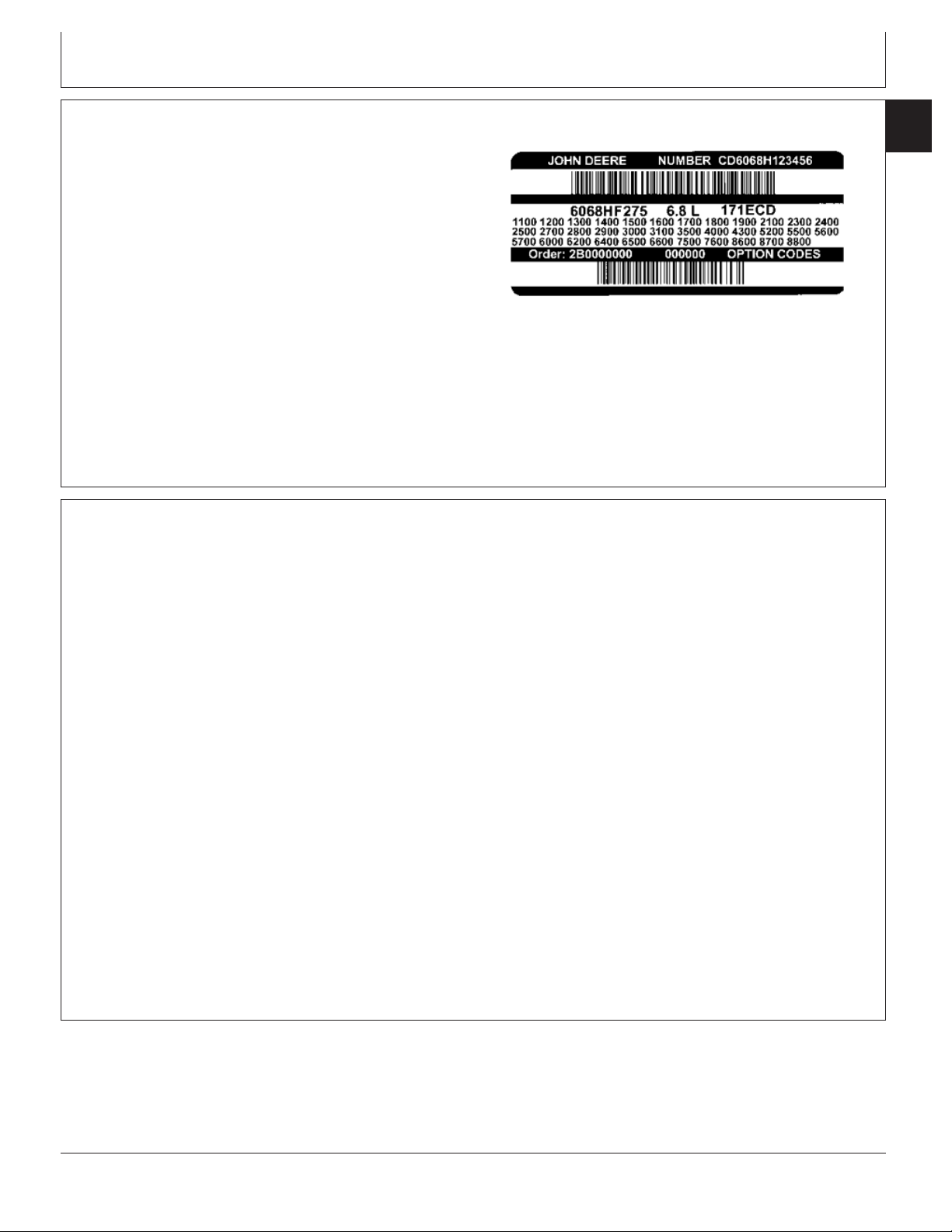
OEM Engine Option Code Label
An option code label is secured to the top of the valve
cover and identifies the factory installed options on each
OEM engine to ensure correct parts acquisition.
Always provide option code information and engine base
code when ordering repair parts. A listing of option codes
is given in parts catalogs and operator’s manuals.
NOTE: Before “hot tank” cleaning, ensure that option
codes are recorded elsewhere.
Information Relative to Emissions Regulations
01
001
3
RG12027 –UN–03DEC01
OUO1080,000020E –19–26NOV01–1/1
Depending on the final destination, engines can meet
the emissions regulations according to the US
Environmental Protection Agency (EPA), California Air
Resources Board (CARB) and for Europe, the
Directive 97/68/EC relating the measures against the
emissions of particles and gaseous pollutant from
internal combustion engines. Such engines are called
“CERTIFIED” and receive an emission label stuck on
the engine.
The regulations prohibit tampering with the
emission-related components listed below which would
render that component inoperative or to make any
adjustment on the engine beyond published
specifications. It is also illegal to install a part or
component where the principle effect of that
component is to bypass, defeat, or render inoperative
any engine component or device which would affect
the engine’s conformance to the emission regulations.
To summarize, it is illegal to do anything except
return the engine to its original published
specifications.
List of emission-related components:
• Fuel injection system
• Intake manifold
• Turbocharger
• Charge air cooling system
• Piston
OUO1080,0000035 –19–29AUG01–1/1
CTM331 (03OCT05)
01-001-3
4.5 L & 6.8 L Level 12 Electronic Fuel System
012506
PN=19
Page 20

Engine Identification
01
001
Engine Application Charts
4
Machine Model Engine Model
Waterloo - Tractors
5425 Tractor PE4045TLV53
5525 Tractor PE4045TLV54
7220 Tractor PE6068HRW59
7320 Tractor PE6068HRW59
7420 Tractor PE6068HRW60
7520 Tractor PE6068HRW60
7815 Tractor PE6068HRW63
Mannheim, Germany
6020SE Tractor (R2) CD4045TL270
6120, 6120SE Tractor (R2) CD4045TL271
6215 Advantage Tractor (NA) CD4045TL272
6215 Classic Tractor (R2) CD4045TL272
6220, 6220SE Tractor (R2) CD4045TL272
6320SE Tractor (R2) CD4045HL270
6415 Advantage Tractor (NA) CD4045HL272
6420SE Tractor (R2) CD4045HL271
6515 Classic Tractor (R2) CD6068HL270
6520L Tractor (NA) CD4045HL273
6520SE Tractor (R2) CD6068TL270
6615 Advantage Tractor (NA) CD6068TL271, CD6068HL271
6620SE Tractor 6068HL272
6715 Advantage Tractor (NA) CD6068TL273, CD6068HL273
JOHN DEERE AGRICULTURAL EQUIPMENT
Zweibrucken, Germany
3215 TeleHandler CD4045HZ061, CD4045HZ275
3220 TeleHandler CD4045HZ060, CD4045HZ275
3415 TeleHandler CD4045HZ061, CD4045HZ275
3420 TeleHandler CD4045HZ060, CD4045HZ275
3700 TeleHandler CD4045TZ060
3800 TeleHandler CD4045HZ060
Continued on next page
OUO1089,0000205 –19–23SEP05–1/2
CTM331 (03OCT05)
01-001-4
4.5 L & 6.8 L Level 12 Electronic Fuel System
012506
PN=20
Page 21

Engine Identification
JOHN DEERE CONSTRUCTION & FORESTRY EQUIPMENT
Application Engine Model
Dubuque
310G Backhoe Loader PE4045DT058, T04045DT058
310G Backhoe Loader (Alt Comp) PE4045TT088, T04045TT088
310SG Backhoe Loader PE4045TT089, T04045TT089
315SG Backhoe Loader PE4045TT089, T04045TT089
710G Backhoe PE6068TT057
450H Crawler Dozer (Alt Comp) PE4045TT084, T04045TT084
450H Crawler Dozer (Nat Asp) PE4045DT058, T04045DT058
450H LGP Crawler Dozer PE4045TT085, T04045TT085
550H Crawler Dozer PE4045TT087, T04045TT087
550H LGP Crawler Dozer PE4045TT086, T04045TT086
650H Crawler Dozer PE4045HT050
700H Crawler Dozer PE6068TT060
710G Backhoe Loader PE6068TT057
Saltillo, Mexico
120C Excavator PE4045HP050
160C LC Excavator PE4045HP051
Deere-Hitachi - Kernersville
200LC Excavator PE6068HT059
Forestry
810 Forwarder CD4045HTJ75
543 DTT Feller Buncher Harvester PE6068HDW62
640 DTT Feller Buncher Harvester PE6068HDW62
1010 Forwarder T04045HTJ76, CD4045HTJ76
1110 Forwarder CD6068HTJ75
1058 Forwarder T04045HTJ76
1410 Forwarder CD6068HTJ77
1458 Forwarder CD6068HTJ77
770 Harvester CD6068HTJ77
770D Wheel Harvester CD4045HTJ77
863 Harvester CD6068HTJ77
1070 Harvester CD6068HTJ76
1063 Harvester CD6068HTJ76
548 Skidder PE6068HDW59
648DD/648TC Skidder PE6068HDW60
01
001
5
JOHN DEERE OEM (OUTSIDE EQUIPMENT MANUFACTURERS)
CD4045TF275
CD4045TFM75 Marine Engine
PE4045HF275
CD4045TF275
PE4045TF275
CD6068HF275
PE6068HF275
CD6068TF275
PE6068TF275
CTM331 (03OCT05)
01-001-5
OUO1089,0000205 –19–23SEP05–2/2
4.5 L & 6.8 L Level 12 Electronic Fuel System
012506
PN=21
Page 22

01
001
Engine Identification
6
CTM331 (03OCT05)
01-001-6
4.5 L & 6.8 L Level 12 Electronic Fuel System
012506
PN=22
Page 23

Lubricants and Coolant
NOTE: Refer to Section 01, Group 002 of CTM104 Base
Engine Manual for information on lubricants and
coolants.
Diesel Fuel
Group 002
Fuels
01
002
1
DPSG,OUO1004,2761 –19–16MAY00–1/1
Consult your local fuel distributor for properties of the
diesel fuel available in your area.
In general, diesel fuels are blended to satisfy the low
temperature requirements of the geographical area in
which they are marketed.
Diesel fuels specified to EN 590 or ASTM D975 are
recommended.
Required fuel properties
In all cases, the fuel must meet the following
properties:
Cetane number of 45 minimum. Cetane number
greater than 50 is preferred, especially for
temperatures below -20°C (-4°F) or elevations above
1500 m (5000 ft).
Cold Filter Plugging Point (CFPP) below the
expected low temperature OR Cloud Point at least
5°C(9°F) below the expected low temperature.
Fuel lubricity should pass a minimum load level of
3100 grams as measured by ASTM D6078 or,
maximum scar diameter of 0.45 mm as measured by
ASTM D6079.
Sulfur content:
• Diesel fuel quality and fuel sulfur content must
comply with all existing regulations for the area in
which the engine operates.
• Sulfur content less than 0.05% (500 ppm) is
preferred.
• If diesel fuel with sulfur content greater than 0.05%
(500 ppm) is used, crankcase oil service intervals
may be affected. (See recommendation for Diesel
Engine Oil.)
• DO NOT use diesel fuel with sulfur content greater
than 1.0%.
IMPORTANT: DO NOT mix used engine oil or any
other type of lubricating oil with
diesel fuel.
CTM331 (03OCT05)
01-002-1
OUOD002,0000171 –19–23SEP05–1/1
4.5 L & 6.8 L Level 12 Electronic Fuel System
012506
PN=23
Page 24

01
002
Bio-Diesel Fuel
2
Consult your local fuel distributor for properties of the
bio-diesel fuel available in your area.
Bio-diesel fuels may be used ONLY if the bio-diesel
fuel properties meet the latest edition of ASTM PS121,
DIN 51606 or equivalent specification.
It has been found that bio-diesel fuels may improve
lubricity in concentrations up to a 5% blend in
petroleum diesel fuel.
When using a blend of bio-diesel fuel, the engine oil
level must be checked daily when the air temperature
is -10°C (14°F) or lower. If the oil becomes diluted with
fuel, shorten oil change intervals accordingly.
IMPORTANT: Raw pressed vegetable oils are NOT
acceptable for use for fuel in any
concentration in John Deere
engines.
These oils do not burn completely,
and will cause engine failure by
leaving deposits on injectors and in
the combustion chamber.
Fuels
A major environmental benefit of bio-diesel fuel is its
ability to biodegrade. This makes proper storage and
handling of bio-diesel fuel especially important. Areas
of concern include:
• Quality of new fuel
• Water content of the fuel
• Problems due to aging of the fuel
Potential problems resulting from deficiencies in the
above areas when using bio-diesel fuel in
concentrations above 5% may lead to the following
symptoms:
• Power loss and deterioration of performance
• Fuel leakage
• Corrosion of fuel injection equipment
• Coked and/or blocked injector nozzles, resulting in
engine misfire
• Filter plugging
• Lacquering and/or seizure of internal components
• Sludge and sediments
• Reduced service life of engine components
Testing Diesel Fuel
DIESELSCAN is a John Deere fuel analysis program
that can be used to monitor the quality of your fuel. The
DIESELSCAN analysis verifies fuel type, cleanliness,
water content, suitability for cold weather operation, and
whether the fuel meets specifications.
Check with your John Deere dealer for availability of
DIESELSCAN kits.
DIESELSCAN is a trademark of Deere & Company
CTM331 (03OCT05)
01-002-2
RG41183,0000046 –19–18DEC01–1/1
DX,FUEL6 –19–14NOV05–1/1
4.5 L & 6.8 L Level 12 Electronic Fuel System
012506
PN=24
Page 25

Lubricity of Diesel Fuel
Diesel fuel must have adequate lubricity to ensure
proper operation and durability of fuel injection system
components.
Diesel fuels for highway use in the United States and
Canada require sulfur content less than 0.05% (500
ppm).
Diesel fuel in the European Union requires sulfur
content less than 0.05% (500 ppm).
Experience shows that some low sulfur diesel fuels
may have inadequate lubricity and their use may
reduce performance in fuel injection systems due to
inadequate lubrication of injection pump components.
The lower concentration of aromatic compounds in
these fuels also adversely affects injection pump seals
and may result in leaks.
Fuels
01
002
3
Use of low lubricity diesel fuels may also cause
accelerated wear, injection nozzle erosion or corrosion,
engine speed instability, hard starting, low power, and
engine smoke.
Fuel lubricity should pass a minimum load level of
3100 gram as measured by the ASTM D6078 or
maximum scar diameter of 0.45 mm as measured by
ASTM D6079.
ASTM D975 and EN 590 specifications do not require
fuels to pass a fuel lubricity test.
If fuel of low or unknown lubricity is used, add John
Deere PREMIUM DIESEL FUEL CONDITIONER (or
equivalent) at the specified concentration.
OUOD002,0000179 –19–18DEC01–1/1
CTM331 (03OCT05)
01-002-3
4.5 L & 6.8 L Level 12 Electronic Fuel System
012506
PN=25
Page 26

01
002
Fuels
4
CTM331 (03OCT05)
01-002-4
4.5 L & 6.8 L Level 12 Electronic Fuel System
012506
PN=26
Page 27

Section 02
Repair and Adjustments
Page Page
Group 090—Electronic Fuel System Repair and
Adjustments
Fuel System—General Information .........02-090-1
Relieve Fuel System Pressure ............02-090-1
Remove and Install Final Fuel Filter/Water
Bowl and/or Pre-Filter/Water Bowl Base . . .02-090-2
Fuel Pre-Filter/Water Bowl Assembly
(Optional)...........................02-090-5
Final Fuel Filter Assembly................02-090-6
Replace Final Fuel Filter/Water Bowl and
Pre-Filter/Water Bowl..................02-090-7
Remove Fuel Supply Pump...............02-090-9
Install Fuel Supply Pump................02-090-10
Injection Pump Static Timing.............02-090-10
Remove Injection Pump ................02-090-11
Inspect Injection Pump Drive Gear ID and
Shaft OD ..........................02-090-13
Install Injection Pump ..................02-090-13
Remove Fuel Injection Nozzles...........02-090-16
Clean Fuel Injection Nozzle Bore .........02-090-18
Clean Fuel Injection Nozzles.............02-090-18
Fuel Injection Nozzle Test...............02-090-19
Disassemble Fuel Injection Nozzles .......02-090-22
Adjust Fuel Injection Nozzle .............02-090-23
Install Seals on Fuel Injection Nozzle ......02-090-24
Install Fuel Injection Nozzles.............02-090-25
Bleed the Fuel System .................02-090-26
Contents
Remove Blade Terminals from Connector
Body .............................02-110-11
Repair (Pull Type) METRI-PACK
Connectors ........................02-110-12
Repair (Push Type) METRI-PACK
Connectors ........................02-110-14
Repair DEUTSCH Connectors ..........02-110-17
Repair AMP Connector .................02-110-20
02
Group 110—Electrical Engine Control Repair and
Adjustment
Engine Control Unit (ECU) ...............02-110-1
Remove and Install Engine Coolant
Temperature Sensor ..................02-110-2
Remove and Install Loss of Coolant
Temperature Sensor ..................02-110-2
Replace Crankshaft Position Sensor ........02-110-3
Remove and Install Oil Pressure Sensor.....02-110-3
Remove and Install Manifold Air Temperature
Sensor.............................02-110-4
Remove and Install Fuel Temperature
Sensor.............................02-110-4
Remove and Install Fuel Heater ...........02-110-5
Connectors ...........................02-110-6
Use Electrical Insulating Compound ........02-110-6
Using High-Pressure Washer .............02-110-7
Repair WEATHERPACK Connector .......02-110-8
CTM331 (03OCT05)
02-1
4.5 L & 6.8 L Level 12 Electronic Fuel System
012506
PN=1
Page 28

02
Contents
CTM331 (03OCT05)
02-2
4.5 L & 6.8 L Level 12 Electronic Fuel System
012506
PN=2
Page 29

Electronic Fuel System Repair and Adjustments
Fuel System—General Information
Group 090
Stanadyne DE10 pumps are static lock-pin timed
during installation of the injection pump.
The fuel supply pump is a separate component
mounted on upper right-hand side of engine block and
is actuated by a pin in block that rides on engine
camshaft lobe.
Engines may be equipped with an optional fuel
pre-filter/water bowl.
Relieve Fuel System Pressure
CAUTION: Escaping diesel fuel under pressure
can have sufficient force to penetrate the skin,
causing serious injury. Before disconnecting
lines, be sure to relieve pressure. Before
applying pressure to the system, be sure ALL
connections are tight and lines, pipes and
hoses are not damaged. Keep hands and body
away from pinholes and nozzles which eject
fluid under pressure. Use a piece of cardboard
or wood, rather than hands, to search for
suspected leaks.
All engines are equipped with a round final fuel filter
with water bowl. Hand primer on top of filter element is
optional.
All engines use Stanadyne Rate Shaping Nozzles
(RSN).
Field-installed options include fuel heater, water bowl
and hand fuel primer.
OUO1089,00001F7 –19–06NOV01–1/1
High Pressure Fluids
02
090
1
X9811 –UN–23AUG88
If ANY fluid is injected into the skin, it must be
surgically removed within a few hours by a
doctor familiar with this type injury or gangrene
may result. Doctors unfamiliar with this type of
injury may call the Deere & Company Medical
Department in Moline, Illinois, or other
knowledgeable medical source.
Any time the fuel system has been opened up for service
(lines disconnected or filters removed), it will be necessary
to bleed air from the system. See BLEED THE FUEL
SYSTEM in this group.
CTM331 (03OCT05)
02-090-1
RG,35,JW7625 –19–20NOV97–1/1
4.5 L & 6.8 L Level 12 Electronic Fuel System
012506
PN=29
Page 30

Electronic Fuel System Repair and Adjustments
Remove and Install Final Fuel Filter/Water Bowl and/or Pre-Filter/Water Bowl Base
Refer to operator’s manual for proper servicing and
(hourly) replacement intervals.
02
090
2
Engines are equipped with a final fuel filter/water bowl (A)
and may have an optional pre-filter/water bowl.
Final fuel filters/water bowls can be equipped with a
transparent (see-through) water collection bowl and/or
hand primer on machines equipped with only one filter.
A—Final Fuel Filter/Water Bowl
Continued on next page
Final Fuel Filter
RG11989 –UN–15NOV01
OUO1089,00001F6 –19–06NOV01–1/3
CTM331 (03OCT05)
02-090-2
4.5 L & 6.8 L Level 12 Electronic Fuel System
012506
PN=30
Page 31

Electronic Fuel System Repair and Adjustments
1. Thoroughly clean fuel filter/pre-filter assemblies and
surrounding area to keep from getting dirt and debris
into fuel system.
2. Connect a drain line to filter drain adapters and drain
all fuel from system.
NOTE: The fuel filters are keyed to the filter header. If
both pre-filter and final filter are removed, ensure
that they are reinstalled in the correct headers.
3. Remove final fuel filter element and pre-filter/water
bowl, if desired. See REPLACE FINAL FUEL
FILTER/WATER BOWL AND PRE-FILTER/WATER
BOWL, in this group.
NOTE: Pre-filter and final filter fuel lines may be
connected to different filter inlet and outlet ports
depending on engine application. Mark fuel line
location to aid during assembly. Refer to markings
on fuel filter base for fuel inlet/outlet ports, as they
are different between the pre- and final filter
bases.
4. Disconnect fuel lines from all ports.
5. Remove final fuel filter base (A).
6. If equipped, remove pre-filter base.
02
090
3
RG12021 –UN–26NOV01
Final Fuel Filter Base
A—Final Fuel Filter Base
7. Replace parts as necessary.
8. Install mounting brackets and tighten to torque
specifications provided below.
Final Fuel Filter
Bracket-to-Cylinder Head—
Torque 73 N•m (54 lb-ft).............................................................................
Final Fuel Filter Mounting
Base-to-Bracket—Torque 73 N•m (54 lb-ft)................................................
Fuel Pre-Filter Bracket-to-Cylinder
Head and Alternator—Torque 73 N•m (54 lb-ft).........................................
Fuel Pre-Filter/Water Bowl
Mounting Base-to-Bracket—
Torque 50 N•m (36 lb-ft).............................................................................
Specification
CTM331 (03OCT05)
Continued on next page
02-090-3
OUO1089,00001F6 –19–06NOV01–2/3
4.5 L & 6.8 L Level 12 Electronic Fuel System
012506
PN=31
Page 32

Electronic Fuel System Repair and Adjustments
9. Install pre-filter and final filter fuel filter/water bowl
elements. See REPLACE FINAL FUEL
FILTER/WATER BOWL AND PRE-FILTER/WATER
BOWL, in this group.
02
10. Connect fuel lines to all ports.
090
4
11. Bleed the fuel system. See BLEED THE FUEL
SYSTEM in this group.
OUO1089,00001F6 –19–06NOV01–3/3
CTM331 (03OCT05)
02-090-4
4.5 L & 6.8 L Level 12 Electronic Fuel System
012506
PN=32
Page 33

Electronic Fuel System Repair and Adjustments
Fuel Pre-Filter/Water Bowl Assembly (Optional)
A—Drain Adapter
B—Packing
C—Cap Screw
D—Water Bowl
E—Retaining Ring
F—Filter Element
G—Filter Base with Seal Ring
H—Vent Plug
I—Packing
J—Plug (2 used)
K—Diaphragm
L—Spring Seat
M—Spring
N—Spring Cover
O—Pump Knob
P—Retaining Ring
02
090
5
RGT7751HR –UN–19NOV97RGT7751HS –UN–19NOV97
CTM331 (03OCT05)
02-090-5
Primary Filter/Water Bowl Assembly
RG,35,JW7623 –19–21JAN02–1/1
4.5 L & 6.8 L Level 12 Electronic Fuel System
012506
PN=33
Page 34

Final Fuel Filter Assembly
1—Retaining Ring
2—O-Ring
02
090
6
3—Stem
4—O-Ring
5—Retaining Ring
6—Filter
7—O-Ring
8—O-Ring
9—Drain Adapter
10—Screw
11—O-Ring
12—Water Bowl
13—Adapter
14—O-Ring
15—Fuel Heater (Optional)
16—O-Ring
17—Filter Base
18—Primer Assembly (Optional)
19—Cap
Electronic Fuel System Repair and Adjustments
CTM331 (03OCT05)
02-090-6
Final Fuel Filter
OUO1080,00001FC –19–15NOV01–1/1
4.5 L & 6.8 L Level 12 Electronic Fuel System
012506
PN=34
RG12015 –UN–16NOV01
Page 35

Electronic Fuel System Repair and Adjustments
Replace Final Fuel Filter/Water Bowl and Pre-Filter/Water Bowl
NOTE: Refer to operator’s manual for proper servicing
and (hourly) replacement intervals.
Final fuel filters can be equipped with a
transparent (see-through) water bowl and/or hand
primer on machines equipped with only one filter.
Replacement of pre- and final fuel filter elements
are similar. Differences will be noted. Make sure
correct embossments on filter elements match the
slots in the mounting header.
1. Thoroughly clean fuel filter/water bowl assembly and
surrounding area, if not previously done.
2. Connect a drain line to filter drain adapters and drain
all fuel from filters.
NOTE: Lifting up on retaining ring (A) as it is rotated
helps to get it past raised locators.
02
090
7
RG11990 –UN–15NOV01
Final Fuel Filter Shown
A—Retaining Ring
B—Filter Element
3. Firmly grasp the retaining ring (A) and rotate it
counterclockwise 1/4 turn. Remove ring with filter
element (B).
4. Inspect filter mounting base for cleanliness. Clean as
required.
5. Remove transparent (see-through) water bowl, if
equipped. Drain and clean water bowl. Dry with
compressed air.
6. Install transparent (see-through) water bowl, if
equipped, onto new filter element. Make sure O-ring is
properly installed in the top groove of bowl.
7. Thoroughly inspect filter base dust seal ring. Replace
as needed.
Continued on next page
OUO1089,00001F5 –19–06NOV01–1/2
CTM331 (03OCT05)
02-090-7
4.5 L & 6.8 L Level 12 Electronic Fuel System
012506
PN=35
Page 36

Electronic Fuel System Repair and Adjustments
NOTE: The fuel filters must be indexed properly and the
key on canister must be oriented in slot of
mounting base for correct installation.
8. Install new filter element onto mounting base and
02
090
position element using a slight rocking motion. Be sure
element is properly indexed on mounting base.
8
9. Install retaining ring onto mounting base and tighten
about 1/3 turn until ring “snaps” into the detent. DO
NOT overtighten the retaining ring.
10. Bleed fuel system. See BLEED THE FUEL SYSTEM,
in this group.
OUO1089,00001F5 –19–06NOV01–2/2
CTM331 (03OCT05)
02-090-8
4.5 L & 6.8 L Level 12 Electronic Fuel System
012506
PN=36
Page 37

Electronic Fuel System Repair and Adjustments
Remove Fuel Supply Pump
IMPORTANT: A backup wrench must always be used
when disconnecting fittings or fuel lines
from supply pump to avoid damage to
fittings.
1. Disconnect fuel inlet line (A) and outlet line (B) and cap
connections on fuel supply pump and fuel lines to keep
debris out of fuel system.
2. Remove cap screws (C) and remove fuel supply pump
assembly from cylinder block.
02
090
9
NOTE: The fuel supply pump is driven by a push rod (D)
that rides on an eccentric camshaft lobe. The
cylinder head must be removed to remove this
push rod.
3. Cover opening on cylinder block to prevent dirt from
entering the engine.
4. Inspect face of pump lever for wear. If lever face is
worn flat or concave, replace pump.
A—Supply Pump Inlet from Fuel Tank
B—Supply Pump Outlet to Final Fuel Filter
C—Cap Screws
D—Push Rod
Fuel Supply Pump Lines
RG11991 –UN–15NOV01
RG9051 –UN–16MAR98
Remove Fuel Supply Pump
CTM331 (03OCT05)
02-090-9
Fuel Supply Pump Push Rod
OUO1089,00001F8 –19–06NOV01–1/1
4.5 L & 6.8 L Level 12 Electronic Fuel System
012506
PN=37
RG12022 –UN–27NOV01
Page 38

Electronic Fuel System Repair and Adjustments
Install Fuel Supply Pump
IMPORTANT: Apply LOCTITE 242 to threads of supply
pump mounting cap screws (C) and fuel
02
090
10
1. Install the fuel supply pump to cylinder block with
pumping lever resting on top of push rod, using a new
O-ring. Tighten cap screws (C) to specifications.
line fittings when reinstalling supply
pump. DO NOT allow sealant to get into
fuel system.
Fuel Supply Pump Cap Screws—
Specification
Torque 30 N•m (22 lb-ft).............................................................................
IMPORTANT: ALWAYS use a backup wrench when
installing fittings and/or fuel lines onto
supply pump to avoid damage to
fittings.
2. Connect supply pump inlet line (A) and outlet line (B)
and tighten securely.
3. Bleed fuel system. See BLEED THE FUEL SYSTEM in
this group.
Injection Pump Static Timing
Fuel Supply Pump Lines
RG11991 –UN–15NOV01
A—Supply Pump Inlet from Fuel Tank
B—Supply Pump Outlet to Final Fuel Filter
C—Cap Screws
OUO1089,00001FA –19–06NOV01–1/1
Static lock-pin timing is accomplished during installation of
the injection pump. See INSTALL INJECTION PUMP later
in this group.
CTM331 (03OCT05)
02-090-10
OUO1089,00001FB –19–06NOV01–1/1
4.5 L & 6.8 L Level 12 Electronic Fuel System
012506
PN=38
Page 39

Electronic Fuel System Repair and Adjustments
Remove Injection Pump
IMPORTANT: Never steam clean or pour cold water
on a fuel injection pump while the pump
is running or while it is warm. Doing so
may cause seizure of internal rotating
pump parts.
1. Clean the fuel injection pump, lines and area around
the pump with cleaning solvent or a steam cleaner.
2. Rotate engine to TDC of number 1 cylinder
compression stroke and install JDG1571 Timing Pin in
flywheel.
02
090
11
3. Before removing injection pump from engine, install
JDG1559 Injection Pump Timing Pin (A) into pump
timing pin bore.
4. Remove injection pump drive gear cover (shown
removed). Remove drive gear retaining nut and washer
from end of pump shaft. Be careful not to let washer
fall inside timing gear cover.
5. Attach JDG1560 Drive Gear Puller to injection pump
drive gear (B) using two screws (C).
6. Evenly tighten the two screws (C) and snugly tighten
center forcing screw (D) against end of pump shaft.
7. Tighten center forcing screw (D) until pump drive gear
is free from tapered shaft. Remove JDG1560 Puller
from drive gear.
A—JDG1559 Timing Pin
B—Injection Pump Drive Gear
C—Screws (2 used)
D—Center Forcing Screw
Stanadyne DE10 Fuel Injection Pump
RG12002 –UN–16NOV01
RG12036 –UN–21JAN02
JDG1559 Injection Pump Timing Pin
CTM331 (03OCT05)
Continued on next page
02-090-11
Injection Pump Drive Gear Removal
OUO1089,00001FE –19–07NOV01–1/2
4.5 L & 6.8 L Level 12 Electronic Fuel System
RG12000 –UN–21JAN02
012506
PN=39
Page 40

Electronic Fuel System Repair and Adjustments
8. Remove temperature sensor connector (A) and fuel
control solenoid connector (B).
IMPORTANT: ALWAYS use a backup wrench when
02
090
12
loosening or tightening fuel delivery
lines at fuel injection pump, so that the
pump discharge fittings are not altered.
This prevents possible internal pump
damage.
9. Disconnect fuel supply line (D) and return line (C).
10. Remove clamp (E) retaining fuel delivery (pressure)
lines (F).
11. Disconnect all fuel delivery lines (F) from injection
pump and install protective caps.
12. Remove three injection pump mounting stud nuts (G).
Remove injection pump from mounting studs. Place
pump on a clean flat surface and inspect shaft OD
and drive gear as outlined later in this group. See
INSPECT INJECTION PUMP DRIVE GEAR ID AND
SHAFT OD later in this group.
A—Temperature Sensor Connector
B—Fuel Control Solenoid Connector
C—Fuel Return Line
D—Fuel Supply Line
E—Clamp
F—Fuel Delivery Lines
G—Nut (3 used)
Injector Pump Electrical Connector Removal
RG12001 –UN–16NOV01
RG12003 –UN–16NOV01
Disconnect Fuel Delivery Lines
CTM331 (03OCT05)
02-090-12
OUO1089,00001FE –19–07NOV01–2/2
4.5 L & 6.8 L Level 12 Electronic Fuel System
012506
PN=40
Page 41

Electronic Fuel System Repair and Adjustments
Inspect Injection Pump Drive Gear ID and Shaft OD
IMPORTANT: Use a good light source to
thoroughly inspect gear ID and shaft
OD.
1. Inspect injection pump drive gear ID full 360° for
metal transfer as a result of slippage on shaft.
2. Inspect injection pump drive shaft OD full 360° for
presence of metal transfer from gear slippage. If
there is clear evidence of metal transfer on pump
shaft OD or in drive gear ID, injection pump and
drive gear MUST BE replaced.
Install Injection Pump
1. Before installing injection pump on engine, install
JDG1559 Injection Pump Timing Pin (A) into pump
timing pin bore. Install a small punch or screwdriver
into hole in pump drive shaft (B) and turn shaft until
timing pin drops into recess in injection pump drive
shaft.
IMPORTANT: When replacing injection pump drive
gear or installing a new pump, the
tapered surfaces of the pump drive
shaft OD and drive gear ID MUST BE
cleaned to remove protective
coatings and oily residue. Use a
suitable cleaner that does not leave
a residue. Mating surfaces MUST BE
ASSEMBLED DRY and LUBRICANTS
MUST NOT BE USED.
OUO1089,00001FC –19–06NOV01–1/1
A
02
090
13
A—JDG1559 Timing Pin
B—Hole in Drive Shaft
Continued on next page
B
RG12019 –UN–19NOV01
Install Timing Pin
OUO1089,0000204 –19–08NOV01–1/3
CTM331 (03OCT05)
02-090-13
4.5 L & 6.8 L Level 12 Electronic Fuel System
012506
PN=41
Page 42

Electronic Fuel System Repair and Adjustments
NOTE: When rotating engine to TDC of compression
stroke on number 1 cylinder, turn engine only in
direction of rotation to prevent gear backlash.
Backlash of gears is enough to throw the injection
02
090
14
pump timing off by several degrees, resulting in
poor engine performance.
2. Make sure that number 1 cylinder is locked at TDC of
compression stroke and install JDG1571 Timing Pin in
flywheel.
NOTE: Retain JDG1559 Timing Pin (B) in pump during
installation.
3. Install injection pump onto mounting studs and tighten
three pump mounting stud nuts (A) to specification.
Position drive gear while installing pump.
Specification
Injection Pump Mounting Stud
Nuts—Torque 25 N•m (19 lb-ft)..................................................................
4. Install injection pump gear (D) on drive shaft. Install,
but do not tighten, injection pump gear mounting nut
(C).
NOTE: Hold the injection pump gear while applying
torque to prevent the gear from rotating.
5. Rotate gear counterclockwise (viewed from front of
engine) to remove any backlash, and tighten gear
mounting nut to specification.
Specification
Injection Pump Gear Mounting
Nut—Torque 195 N•m (145 lb-ft)................................................................
6. Install injection pump gear access plate and remove
timing pin (B) from pump. Install plug in injection pump
timing pin hole and tighten to specification.
Injection Pump Mounting Stud Nuts
RG12004 –UN–16NOV01
RG12007 –UN–16NOV01
Injection Pump Timing Pin
Injection Pump Timing Pin Plug—
Specification
Torque 9.5 N•m (7.5 lb-ft)...........................................................................
7. Remove JDG1571 Timing Pin from flywheel.
CTM331 (03OCT05)
Continued on next page
02-090-14
Injection Pump Gear Installation
A—Injection Pump Mounting Stud Nut (3 used)
B—JDG1559 Injection Pump Lock Timing Pin
C—Gear Mounting Nut
D—Pump Gear
OUO1089,0000204 –19–08NOV01–2/3
4.5 L & 6.8 L Level 12 Electronic Fuel System
RG12008 –UN–16NOV01
012506
PN=42
Page 43

Electronic Fuel System Repair and Adjustments
8. Connect injection pump fuel delivery (pressure) lines
(F). Beginning with outlet (I) and continuing around the
pump head in counterclockwise direction, attach lines
in same order as engine firing (1-5-3-6-2-4 on
6-cylinder engines and 1-3-4-2 on 4-cylinder engines).
IMPORTANT: ALWAYS use a backup wrench when
loosening or tightening fuel delivery
lines at fuel injection pump, so that the
pump discharge fittings are not altered.
This prevents possible internal pump
damage.
9. Tighten fuel delivery lines at pump to specification.
02
090
15
Injection Pump Fuel Delivery
Specification
(Pressure) Lines—Torque 27 N•m (20 lb-ft)...............................................
10. Install clamp (E).
11. Connect fuel supply line (D) and fuel return line (C).
12. Install temperature sensor connector (A) and fuel
control solenoid connector (B).
13. Bleed air from fuel system as outlined in this group.
See BLEED THE FUEL SYSTEM in this group. Start
engine, run for several minutes and check entire fuel
system for leaks.
A—Temperature Sensor Connector
B—Fuel Control Solenoid Connector
C—Fuel Return Line
D—Fuel Supply Line
E—Clamp
F—Fuel Delivery Lines
G—Nut (3 used)
H—Engine Block Side
I—Outlet Connection to No. 1 Cylinder
Injector Pump Electrical Connectors
RG12001 –UN–16NOV01
RG12003 –UN–16NOV01
Connect Fuel Delivery Lines
CTM331 (03OCT05)
02-090-15
OUO1089,0000204 –19–08NOV01–3/3
4.5 L & 6.8 L Level 12 Electronic Fuel System
012506
PN=43
RG12035 –UN–11JAN02
Page 44

Electronic Fuel System Repair and Adjustments
Remove Fuel Injection Nozzles
General Nozzle Service Precautions
Before removal, thoroughly remove all dirt from the
02
cylinder head around fuel injection nozzles. Clean with
090
compressed air to prevent dirt from entering the cylinders.
16
Plug the bore in the cylinder head after each nozzle has
been removed. Cap fuel line openings as soon as they
are disconnected.
Immediately fit protective caps over the nozzle tips and
the line connections to avoid handling damage and getting
debris in fuel system.
Do not bend the fuel delivery lines, as this may affect their
durability. When loosening the fuel pressure lines, hold
male union of nozzle line stationary with a backup wrench.
1. Loosen tube nuts (A) at each nozzle to remove leak-off
lines and T-fittings as an assembly.
A—Tube Nuts
Fuel Injection Nozzle
RG11993 –UN–15NOV01
OUO1089,00001FF –19–07NOV01–1/4
CTM331 (03OCT05)
Continued on next page
02-090-16
Fuel Leak-Off Lines
OUO1089,00001FF –19–07NOV01–2/4
4.5 L & 6.8 L Level 12 Electronic Fuel System
012506
PN=44
RG11994 –UN–21DEC05
Page 45

Electronic Fuel System Repair and Adjustments
2. Disconnect fuel injection line from nozzle using a
backup wrench on nozzle connection as shown.
3. Remove cap screw securing nozzle in cylinder head
nozzle bore.
02
090
17
4. Pull injection nozzle out of cylinder head using
JDG1515-1 Nozzle Puller (A).
IMPORTANT: Do not use screwdrivers, pry bars, or
similar tools for this as they might
damage the injection nozzle beyond
repair.
A—JDG1515-1 Nozzle Puller
Fuel Injection Line at Nozzle
RG11999 –UN–19NOV01
OUO1089,00001FF –19–07NOV01–3/4
CTM331 (03OCT05)
02-090-17
Injection Nozzle Puller Set
OUO1089,00001FF –19–07NOV01–4/4
4.5 L & 6.8 L Level 12 Electronic Fuel System
012506
PN=45
RG12018 –UN–16NOV01
Page 46

Electronic Fuel System Repair and Adjustments
Clean Fuel Injection Nozzle Bore
IMPORTANT: Always turn tool clockwise in bore to
prevent dulling of cutting edges, even
02
090
Clean injection nozzle bore using JDE39 Nozzle Bore
18
Cleaning Tool (A). Blow debris from bore using
compressed air, and plug the bore to prevent entry of
foreign material.
when removing tool from bore.
A—Nozzle Bore Cleaning Tool
Clean Fuel Injection Nozzles
1. Remove carbon stop seal (A) from groove in nozzle
body using razor blade or sharp knife and remove
upper sealing washer (B). Discard seal and washer.
2. Place nozzle in solvent or clean diesel fuel, so carbon
stop seal groove is submerged, and soak for a while.
IMPORTANT: Do not scrape or disturb the TEFLON
coating on the nozzle body above the
carbon stop seal groove. This coating
will become discolored during normal
operation, but this is not harmful. Do
not use a motor-driven brush to clean
nozzle body.
Clean Injection Nozzle Bore
RG7743 –UN–07NOV97
RG,35,JW7596 –19–20NOV97–1/1
RG11995 –UN–15NOV01
Clean Fuel Injection Nozzle
A—Carbon Stop Seal
B—Upper Sealing Washer
3. After soaking, clean nozzle tip with brass wire brush.
Never use a steel wire brush or scraper.
TEFLON is a registered trademark of the DuPont Co.
CTM331 (03OCT05)
02-090-18
OUO1080,00001FD –19–15NOV01–1/1
4.5 L & 6.8 L Level 12 Electronic Fuel System
012506
PN=46
Page 47

Electronic Fuel System Repair and Adjustments
Fuel Injection Nozzle Test
CAUTION: The nozzle tip should always be
directed away from the operator. Fuel from the
spray orifices can penetrate clothing and skin
causing serious personal injury. Enclosing the
nozzle in a clear glass beaker is recommended.
Before applying pressure to the nozzle tester,
be sure that all connections are tight, and that
the fittings are not damaged. Fluid escaping
from a very small hole can be almost invisible.
To search for suspected leaks, use a piece of
cardboard or wood, rather than hands.
If ANY fluid is injected into the skin, it must be
surgically removed within a few hours by a
doctor familiar with this type injury or gangrene
may result.
NOTE: Testing the performance of a nozzle while the
engine is running is just a rough test. To obtain a
true check of nozzle performance, use a nozzle
tester JT25510 (1) and pressure line KJD10109
(2).
02
090
19
X9811 –UN–23AUG88
High Pressure Fluid
Use only carefully filtered diesel fuel for testing
the injection nozzles, since dirty fuel will severely
damage the precision parts of a nozzle.
Connect the nozzle to the tester so that the axis of the
nozzle forms an angle of approximately 30° to the vertical
and the spray of fuel is directed downwards. Check all
connections for leaks. Close the gauge shut-off valve and
flush (bleed) the nozzle by operating test pump rapidly.
1—Nozzle Tester
2—Pressure Line
Continued on next page
Fuel Injection Nozzle Test
L30741 –UN–08AUG89
OUO1089,0000200 –19–07NOV01–1/3
CTM331 (03OCT05)
02-090-19
4.5 L & 6.8 L Level 12 Electronic Fuel System
012506
PN=47
Page 48

Electronic Fuel System Repair and Adjustments
Spray Pattern Test
Close gauge shut-off valve and operate the pump lever at
60 strokes per minute. If the fuel injection nozzle is
working properly, the fuel should issue through all nozzle
02
orifices in a fine, evenly shaped spray cone. This spray
090
cone is inclined from the centerline of the nozzle body, but
20
should be distributed. For a better check, place a piece of
paper or cardboard at a suitable distance below the
nozzle and check the appearance of the damp circular
spots made by the fuel. Deviations from the regular spray
pattern or angle may be due to the complete or partial
clogging of a nozzle orifice. In this case the fuel issues in
a jet rather than in a fine spray.
Checking Valve Stem and Guide Wear
Connect fuel injection nozzle to the nozzle tester with the
tip raised a little higher than its opposite end.
Cover the tip and pump the tester to a pressure of
10 300 kPa (103 bar) (1500 psi). Keep the pressure
constant and observe how much fuel leaks out of the
nozzle return end. After the first drop has formed, count
the drops for 30 seconds and compare with specification.
Nozzle—Return Leakage at
10 300 kPa (103 bar) (1500 psi) 1 to 14 drops (maximum) within
Fuel Injection Nozzle—Specification
.............
30 seconds
Checking Valve Seat
Connect the nozzle to tester in horizontal position.
Operate the pump lever rapidly to bleed the nozzle and
allow the valve to seat. Dry the tip of the nozzle
thoroughly. Now operate the pump lever slowly until the
indicated pressure is approximately 2800 to 3500 kPa
(28 to 35 bar) (400 to 500 psi) below opening pressure
(see specification for opening pressure). Keep watching
the nozzle. Under these conditions the fluid should not
drip out of the nozzle tip. However some weeping or light
moisture on the tip is considered acceptable. Work the
pump lever quickly several times in succession to make
the nozzle spray in the normal way. After the last stroke of
the pump, observe again. If the nozzle is not quite
leakproof, disassemble for servicing.
CTM331 (03OCT05)
Continued on next page
02-090-20
OUO1089,0000200 –19–07NOV01–2/3
4.5 L & 6.8 L Level 12 Electronic Fuel System
012506
PN=48
Page 49

Electronic Fuel System Repair and Adjustments
Opening Pressure Test
NOTE: Absolute opening pressure is less important than
equal opening pressure of all nozzles.
Close gauge shut-off valve and actuate the pump several
times to allow the nozzle valve to seat properly. Open
gauge shut-off valve. Pump the pressure up to the point
where the pressure gauge needle falls rapidly. This point
(take reading) is the nozzle valve opening pressure.
Rate Shaping Nozzle—Opening
Pressure for Setting
(New or Reconditioned) 24 400—24 900 kPa
Opening Pressure for Checking
(New or Reconditioned) 24 100 kPa (241 bar) (3500 psi)
Opening Pressure for Setting
(Used) 23 000—23 600 kPa
........................................................................
Opening Pressure for Checking
(Used) 21 800 kPa (218 bar) (3170 psi)
.....................................................
Rate Shaping Nozzle—Opening
pressure difference between
cylinders 700 kPa (7 bar) (100 psi) Max.....................................................
Fuel Injection Nozzle—Specification
.............................................
(244—249 bar) (3540—3620 psi)
..........................
Min
(230—236 bar) (3340—3420 psi)
Min
If spray pattern, leakage test, and valve wear test are
good but the opening pressure test is unsatisfactory,
adjust opening pressure.
02
090
21
CTM331 (03OCT05)
02-090-21
OUO1089,0000200 –19–07NOV01–3/3
4.5 L & 6.8 L Level 12 Electronic Fuel System
012506
PN=49
Page 50

Electronic Fuel System Repair and Adjustments
Disassemble Fuel Injection Nozzles
NOTE: If all tests prove that the nozzle performs properly,
no further service is necessary and the nozzle can
02
090
22
be reinstalled. If an injection nozzle is not
operating properly and must be disassembled for
cleaning and/or reconditioning, see your
“Stanadyne” dealer.
A—T-Fitting
B—Cap
C—O-Ring (2 used)
D—Retainer
E—Protection Cap
F—Carbon Stop Seal
G—Seal Washer
H—Protection Cap
RSN Nozzle Disassembly
OUO1089,0000201 –19–07NOV01–1/1
RG11996 –UN–15NOV01
CTM331 (03OCT05)
02-090-22
4.5 L & 6.8 L Level 12 Electronic Fuel System
012506
PN=50
Page 51

Electronic Fuel System Repair and Adjustments
Adjust Fuel Injection Nozzle
CAUTION: Nozzle tip should always be directed
away from operator. Fuel from spray orifices
can penetrate clothing and skin causing serious
personal injury. Enclosing nozzle in a glass
beaker is recommended.
Before applying pressure to nozzle tester, be
sure all connections are tight, and fittings are
not damaged. Fluid escaping from a very small
hole can be almost invisible. Use a piece of
cardboard or wood, rather than hands, to
search for suspected leaks.
If ANY fluid is injected into the skin, it must be
surgically removed within a few hours by a
doctor familiar with this type injury or gangrene
may result.
1. Unscrew spring chamber cap (C) using JDG1521
Spring Chamber Cap Wrench.
02
090
23
X9811 –UN–23AUG88
High Pressure Fluids
2. Loosen and remove lift adjusting screw lock nut (D).
3. Loosen pressure adjusting screw lock nut (E) using
JDG1515-2 Special Wrench.
4. Connect nozzle to tester, then adjust opening pressure
to specifications by turning the pressure adjusting
screw (A). Use JDG1522 Pressure Adjusting Screw
Tool.
5. Tighten pressure adjusting screw lock nut (E) to
specification, then recheck opening pressure.
6. Carefully screw lift adjusting screw (B) until it bottoms
on spring seat (F).
7. Unscrew lift adjusting screw with 7/8 turn.
8. Tighten lift adjusting screw lock nut (D) to specification.
RSN Nozzle Adjust
RG11997 –UN–15NOV01
A—Pressure Adjusting Screw
B—Lift Adjusting Screw
C—Spring Chamber Cap
D—Lift Adjusting Screw Lock Nut
E—Pressure Adjusting Screw Lock Nut
F—Spring Seat
CTM331 (03OCT05)
Continued on next page
02-090-23
OUO1089,0000202 –19–07NOV01–1/2
4.5 L & 6.8 L Level 12 Electronic Fuel System
012506
PN=51
Page 52

9. Recheck opening pressure.
Electronic Fuel System Repair and Adjustments
Pressure Adjusting Screw Lock
Nut—Torque 10 N•m (7 lb-ft)......................................................................
Lift Adjusting Screw Lock Nut—
02
Torque 5 N•m (3.5 lb-ft)..............................................................................
090
24
Fuel Injection Nozzle—Specification
Install Seals on Fuel Injection Nozzle
IMPORTANT: Each time an injection nozzle is
removed from the cylinder head,
replace carbon stop seal (B) with a new
one.
1. Position JD258 (JD-258) Nozzle Carbon Stop Seal
Installer (A) over nozzle tip.
2. Install a new seal washer (C) onto nozzle body.
3. Position a new carbon stop seal (B) on seal installer.
Slide the carbon seal until it seats in its groove on
nozzle body.
NOTE: If nozzle is not going to be installed at this time,
install a No. 16189 Nozzle Protector Cap over
nozzle tip. Plug all other openings in nozzle to
prevent contamination.
OUO1089,0000202 –19–07NOV01–2/2
RG9096 –UN–27MAR98
Fuel Injection Nozzle Seals
A—Carbon Stop Seal Installer
B—Carbon Stop Seal
C—Seal Washer
CTM331 (03OCT05)
02-090-24
RG,35,JW7586 –19–20NOV97–1/1
4.5 L & 6.8 L Level 12 Electronic Fuel System
012506
PN=52
Page 53

Electronic Fuel System Repair and Adjustments
Install Fuel Injection Nozzles
IMPORTANT: Before installing injection nozzles, make
sure nozzles are clean and free from oil
or grease.
NOTE: If nozzle bore in cylinder head must be cleaned,
use JDE39 Nozzle Bore Cleaning Tool. See
REMOVE FUEL INJECTION NOZZLES earlier in
this group.
1. Remove plug (if installed previously) from nozzle bore
in cylinder head and blow out bore with compressed
air.
02
090
25
NOTE: Make sure that the sealing surface of the cylinder
head (on which the seal washer will be resting) is
smooth and free of damage or dirt. This could
prevent proper sealing. Dirt and roughness could
also cause nozzle to be distorted when the
attaching screw is tightened, making the valve
stick.
2. Install nozzle with spacer and clamps in cylinder head
using a slight twisting motion as nozzle is seated in
bore. Illustration shows relationship of parts required
for proper installation.
3. Align nozzle clamps and install cap screw. Do not
tighten cap screw at this stage.
4. Connect fuel pressure line to nozzle. Leave connection
slightly loose until air is bled from system.
5. Tighten nozzle hold-down clamp cap screws to
specifications.
Specification
Fuel Injection Nozzle Hold-Down
Clamp Cap Screws—Torque 40 N•m (30 lb-ft)...........................................
Injection Nozzle in Cylinder Head
RG11998 –UN–19NOV01
6. Install leak-off line assembly.
Fuel Leak-Off Line Hex Nut—
Torque 5 N•m (3.7 lb-ft)
..............................................................................
CTM331 (03OCT05)
Specification
(44 lb-in.)
02-090-25
Continued on next page
4.5 L & 6.8 L Level 12 Electronic Fuel System
OUO1080,0000200 –19–16NOV01–1/2
012506
PN=53
Page 54

Electronic Fuel System Repair and Adjustments
7. Bleed air from loose injection line connection. Tighten
connection using two wrenches to the following
specifications.
02
Fuel Injection Nozzle Delivery
090
Line—Torque 27 N•m (20 lb-ft)...................................................................
26
Specification
See BLEED THE FUEL SYSTEM in this group.
Bleed the Fuel System
CAUTION: Escaping fluid under pressure can
penetrate the skin causing serious injury. Avoid
hazards by relieving pressure before
disconnecting hydraulic or other lines. Tighten
all connections before applying pressure.
Search for leaks with a piece of cardboard.
Protect hands and body from high pressure
fluids.
If an accident occurs, see a doctor immediately.
Any fluid injected into the skin must be
surgically removed within a few hours or
gangrene may result. Doctors unfamiliar with
this type of injury may call the Deere &
Company Medical Department in Moline, Illinois,
or other knowledgeable medical source.
Nozzle Fuel Pressure Line
RG11999 –UN–19NOV01
OUO1080,0000200 –19–16NOV01–2/2
X9811 –UN–23AUG88
High Pressure Fluids
Any time the fuel system has been opened up for service
(lines disconnected or filters removed), it will be necessary
to bleed air from the system.
The fuel system may be bled at one of several locations.
On some engine applications it may be necessary to
consult your operator’s manual and choose the best
location for your engine/machine application.
CTM331 (03OCT05)
02-090-26
Continued on next page
4.5 L & 6.8 L Level 12 Electronic Fuel System
OUO1089,0000203 –19–07NOV01–1/5
012506
PN=54
Page 55

Electronic Fuel System Repair and Adjustments
1. Loosen the air bleed vent screw (A) two full turns by
hand on fuel filter base.
A—Bleed Vent Screw
02
090
27
2. Operate fuel supply pump prime lever (B) or primer
button on fuel filter base (if equipped).
3. Tighten bleed plug securely; continue operating primer
until pumping action is not felt.
4. Start engine and check for leaks.
If engine will not start, it may be necessary to bleed air
from fuel system at fuel injection pump or injection
nozzles as explained next.
B—Primer Lever
Final Fuel Filter Bleed Vent Screw
RG11805 –UN–25OCT01
OUO1089,0000203 –19–07NOV01–2/5
RG11806 –UN–25OCT01
Fuel Supply Pump Primer Lever
CTM331 (03OCT05)
Continued on next page
02-090-27
OUO1089,0000203 –19–07NOV01–3/5
4.5 L & 6.8 L Level 12 Electronic Fuel System
012506
PN=55
Page 56

Electronic Fuel System Repair and Adjustments
At Fuel Injection Pump
1. Loosen fuel return line (A) at fuel injection pump.
2. Operate fuel supply pump primer lever or primer button
02
090
28
on fuel filter base (if equipped).
3. As soon as fuel flow is free from air bubbles, tighten
fuel return line to specifications. Primer lever is
spring-loaded and will return to normal position.
Fuel Injection Pump Return
Specification
Line—Torque 27 N•m (20 lb-ft)...................................................................
At Fuel Injection Nozzles
1. Place throttle lever in half-throttle position.
IMPORTANT: Always use a backup wrench when
loosening or tightening fuel lines at
nozzles and/or injection pump to avoid
damage.
2. Using two open-end wrenches, loosen two fuel line
connections at injection nozzles.
3. Crank engine over with starter motor for 15 seconds
(but do not start engine) until fuel without any air
bubbles flows out of loosened connection. Retighten
connection to specifications.
Fuel Injection Pump Return Line
RG11807 –UN–25OCT01
A—Fuel Return Line
OUO1089,0000203 –19–07NOV01–4/5
RG11808 –UN–25OCT01
Nozzle Fuel Pressure Line
Fuel Injection Nozzle Delivery
Lines—Torque 27 N•m (20 lb-ft).................................................................
Specification
4. Repeat procedure for remaining injection nozzles (if
necessary) until all air has been removed from fuel
system.
If engine still will not start, see your authorized servicing
dealer or engine distributor.
CTM331 (03OCT05)
02-090-28
OUO1089,0000203 –19–07NOV01–5/5
4.5 L & 6.8 L Level 12 Electronic Fuel System
012506
PN=56
Page 57

Electrical Engine Control Repair and Adjustment
Engine Control Unit (ECU)
IMPORTANT: DO NOT pressure wash the Engine
Control Unit (ECU).
Group 110
Before welding on engines with ECU,
protect the ECU from high-current
damage as follows:
1. Disconnect ECU-to-vehicle frame
ground connection.
2. Disconnect all other connectors from
ECU. Also disconnect module
connector at injector pump.
3. Connect welder ground close to
welding point and make sure ECU
and other electrical components are
not in the ground path.
NOTE: For diagnosis and testing of the electronic engine
control and sensors, refer to Group 150.
IMPORTANT: DO NOT OPEN ENGINE CONTROL
UNIT.
NOTE: The sealed ECU assembly is the system
component LEAST likely to fail. Ensure that it is
isolated and identified as the defective component
before replacing. See operation and test manual
for proper troubleshooting procedures.
02
110
1
RG12006 –UN–15NOV01
Engine Control Unit (ECU)
The ECU is not repairable. If it is found to be defective,
replace it as a unit. Provide the 13-digit engine serial
number when ordering a new ECU.
IMPORTANT: If an ECU is not programmed identically
with the original (failed) ECU,
misleading diagnostic messages, poor
performance, or engine damage can
occur.
OUO1080,0000201 –19–16NOV01–1/1
CTM331 (03OCT05)
02-110-1
4.5 L & 6.8 L Level 12 Electronic Fuel System
012506
PN=57
Page 58

Electrical Engine Control Repair and Adjustment
Remove and Install Engine Coolant Temperature Sensor
1. Disconnect engine coolant temperature sensor wiring
02
110
connector and remove sensor.
2
2. Coat sensor O-ring with JDT405 High Temperature
Grease and install sensor in thermostat housing.
Tighten to specifications.
Engine Coolant Temperature
Specification
Sensor—Torque 15 N•m (11 lb-ft)..............................................................
3. Install sensor wiring connector.
Remove and Install Loss of Coolant Temperature Sensor
1. Disconnect loss of coolant temperature sensor wiring
connector and remove sensor.
2. Coat sensor O-ring with JDT405 High Temperature
Grease and install sensor in the rear of the cylinder
head. Tighten to specifications.
Specification
Loss of Coolant Temperature
Sensor—Torque 35 N•m (26 lb-ft)..............................................................
Engine Coolant Temperature Sensor
RG12009 –UN–16NOV01
A—Engine Coolant Temperature Sensor
OUO1080,0000202 –19–16NOV01–1/1
RG10766 –UN–26MAY00
Loss of Coolant Temperature (Rear of Cylinder Head)
3. Install sensor wiring connector.
CTM331 (03OCT05)
02-110-2
A—Loss of Coolant Temperature Sensor
RG40854,000014A –19–11FEB02–1/1
4.5 L & 6.8 L Level 12 Electronic Fuel System
012506
PN=58
Page 59

Electrical Engine Control Repair and Adjustment
Replace Crankshaft Position Sensor
1. Disconnect sensor wiring connector.
2. Using a deep well socket, remove crankshaft position
sensor (A).
3. Replace sensor and O-ring in timing gear cover.
Tighten sensor to specifications.
Specification
Crankshaft Position Sensor—
Torque 14 N•m (10 lb-ft).............................................................................
4. Install sensor wiring connector.
Remove and Install Oil Pressure Sensor
1. Disconnect oil pressure sensor wiring connector
(shown disconnected) and remove sensor from cylinder
block.
2. Coat threads of sensor with LOCTITE592 Pipe
Sealant with TEFLON. Install sensor in oil cooler
housing and tighten to specifications.
02
110
3
RG12011 –UN–16NOV01
Crankshaft Position Sensor
A—Crankshaft Position Sensor
OUO1080,0000203 –19–16NOV01–1/1
Oil Pressure Sensor—Torque 15 N•m (11 lb-ft).........................................
Specification
3. Install sensor wiring connector.
LOCTITE is a registered trademark of Loctite Corp.
TEFLON is a registered trademark of Du Pont Co.
Oil Pressure Sensor
RG10550 –UN–02DEC99
OUO1080,0000204 –19–16NOV01–1/1
CTM331 (03OCT05)
02-110-3
4.5 L & 6.8 L Level 12 Electronic Fuel System
012506
PN=59
Page 60

Electrical Engine Control Repair and Adjustment
Remove and Install Manifold Air Temperature Sensor
1. Disconnect air temperature sensor wiring connector
02
110
and remove sensor (A) from air intake line.
4
2. Replace O-ring and install sensor in air intake line.
Tighten sensor to specifications.
Manifold Air Temperature
Specification
Sensor—Torque 10 N•m (7 lb-ft)................................................................
3. Install sensor wiring connector.
Remove and Install Fuel Temperature Sensor
1. Disconnect fuel temperature sensor wiring connector
and remove sensor (A) from fuel injection pump.
2. Replace O-ring and install sensor into fuel injection
pump and tighten to specifications.
Specification
Fuel Temperature Sensor—
Torque 13—18 N•m (10—13 lb-ft)..............................................................
3. Install sensor wiring connector.
Manifold Air Temperature Sensor
RG12013 –UN–16NOV01
A—Manifold Air Temperature Sensor
OUO1080,00001F5 –19–09NOV01–1/1
A— Fuel Temperature Sensor
CTM331 (03OCT05)
02-110-4
Fuel Temperature Sensor
OUO1080,00001F6 –19–12NOV01–1/1
4.5 L & 6.8 L Level 12 Electronic Fuel System
012506
PN=60
RG12014 –UN–16NOV01
Page 61

Electrical Engine Control Repair and Adjustment
Remove and Install Fuel Heater
1. Disconnect fuel heater wiring connector and remove
heater from filter base.
2. Replace O-ring and install fuel heater in primary fuel
filter inlet port to specifications.
Specification
Fuel Heater—Torque 9 N•m (7 lb-ft)...........................................................
3. Install heater wiring connector.
02
110
5
RG12016 –UN–16NOV01
Fuel Heater
OUO1080,00001F7 –19–12NOV01–1/1
CTM331 (03OCT05)
02-110-5
4.5 L & 6.8 L Level 12 Electronic Fuel System
012506
PN=61
Page 62

Electrical Engine Control Repair and Adjustment
Connectors
Connectors are devices that provide for assembly and
disassembly of systems. Connectors should always be
serviced using tools designed for that type of connector. A
02
good crimp is important to mechanical and electrical
110
soundness. Repaired connectors should be physically
6
tested by pulling to be sure the contact is firmly attached
to the conductor.
IMPORTANT: If for some reason the connectors are
not connected, such as when the fuel
injection pump is removed, it is
important to protect the connectors
from debris.
Refer to the procedures which follow for repair of various
types of connectors.
Use Electrical Insulating Compound
Apply AT66865 Compound directly to the terminals
between the wire seal and connector body. This provides
a moisture barrier, especially in wet and humid conditions.
RG,RG34710,1328 –19–23OCT97–1/1
RG,RG34710,1335 –19–23OCT97–1/1
CTM331 (03OCT05)
02-110-6
4.5 L & 6.8 L Level 12 Electronic Fuel System
012506
PN=62
Page 63

Electrical Engine Control Repair and Adjustment
Using High-Pressure Washer
IMPORTANT: Reduce pressure when directing
pressurized water at electronic or
electrical components and connectors
as this may cause the components to
malfunction. Always reduce pressure,
and spray at a 45 to 90 degree angle.
02
110
7
Using High-Pressure Washer
RG,RG34710,1329 –19–23OCT97–1/1
T6642EJ –UN–18OCT88
CTM331 (03OCT05)
02-110-7
4.5 L & 6.8 L Level 12 Electronic Fuel System
012506
PN=63
Page 64

Electrical Engine Control Repair and Adjustment
Repair WEATHERPACK Connector
1. Disconnect WEATHERPACK connector. Remove the
tie bands and tape.
02
2. Open the secondary lock on the back of the connector.
110
8
3. Identify wire color/number to the connector cavity.
Make sure each wire goes back to the correct cavity
location.
4. Insert JDG364 Extraction Tool1over terminal contact in
connector body. Extraction tool needs to be fully
seated to unlock terminal tangs from the connector
body. When tool is seated, gently pull the wire from the
back of the connector. If the wire(s) or terminal(s) are
being repaired, go to step 5. If the wires and terminals
are OK and only the connector is being replaced, go to
step 9.
5. Using JDG145 Universal Electrical Pliers2, cut off wire
directly behind the terminal seal crimp. If any part of
the seal is still on the wire, dispose of it.
TS0128 –UN–23AUG88
6. Using JDG145 Universal Electrical Pliers2, strip 6 mm
(1/4 in.) insulation from end of wire.
WEATHERPACK is a trademark of Packard Electric
1
Included in JT07195B Electrical Repair Kit
2
Included in JDG155 Electrical Repair Tool Kit
Continued on next page
AG,OUOD008,296 –19–06MAR02–1/4
CTM331 (03OCT05)
02-110-8
4.5 L & 6.8 L Level 12 Electronic Fuel System
012506
PN=64
Page 65

Electrical Engine Control Repair and Adjustment
7. Select correct size of seal. Slide the seal over the wire
insulation with the smaller diameter side facing the end
of the wire. Small diameter side of seal should line up
with the outer edge of the insulation.
IMPORTANT: The seal must fit snug over the cable
insulation without a gap between the
cable seal and the insulation.
NOTE: Cable seals are color coded for three sizes of
wire:
•
Green - 18—20 Gauge Wire
•
Gray - 14—16 Gauge Wire
•
Blue - 10—12 Gauge Wire
8. Select correct size terminal on wire and crimp in
position with a W-type crimp using a JDG783
WEATHER PACK Crimping Tool.
NOTE: Terminals have numbered identification for two
sizes of wire:
•
#15 - 14—16 Gauge Wire
•
#19 - 18—20 Gauge Wire
02
110
9
TS0136 –UN–23AUG88
AG,OUOD008,296 –19–06MAR02–2/4
WEATHER PACK is a trademark of Packard Electric
CTM331 (03OCT05)
Continued on next page
02-110-9
AG,OUOD008,296 –19–06MAR02–3/4
4.5 L & 6.8 L Level 12 Electronic Fuel System
012506
PN=65
TS1623 –UN–02NOV94
Page 66

Electrical Engine Control Repair and Adjustment
9. Insert terminal into connector. Terminal should click
when it is fully seated. Make sure the wire is inserted
into the correct connector cavity.
IMPORTANT: Terminal tangs must be carefully spread
02
110
10
to ensure good seating on connector
body. If terminal is being reused in a
new connector, make sure tangs are
spread.
NOTE: Connector bodies are “keyed” for correct
terminals. Be sure terminals are correctly aligned.
Correct terminal installation for sleeve (A) and pin
(B) is illustrated.
10. Gently pull on wire to insure that the terminal is
locked in position.
11. Repair or transfer remaining wires.
12. Close the secondary lock on the back of the
connector.
TS0130 –UN–23AUG88TS0139 –UN–02DEC88
13. Retape wires and add the required tie bands to the
harness.
A—Sleeve
B—Pin
AG,OUOD008,296 –19–06MAR02–4/4
CTM331 (03OCT05)
02-110-10
4.5 L & 6.8 L Level 12 Electronic Fuel System
012506
PN=66
Page 67

Electrical Engine Control Repair and Adjustment
Remove Blade Terminals from Connector Body
NOTE: Use JDG776 Extraction Tool with 56, 280, and
630 Series METRI-PACK terminals. Use JDG777
Extraction Tool with 150 Series METRI-PACK
terminals.
02
110
11
1. Insert JDG776 or JDG777 Terminal Extraction Tool
1
into connector body pushing the terminal locking tang
inward.
2. Gently pull wire and remove terminal from connector.
3. Adjust the locking tang on the terminal to it’s original
position before installing into a connector.
1
Included in JT07195B Electrical Repair Kit
RW4218 –UN–23AUG88
A—Locking Tang
B—Original Position
AG,OUOD008,297 –19–06MAR02–1/1
CTM331 (03OCT05)
02-110-11
4.5 L & 6.8 L Level 12 Electronic Fuel System
012506
PN=67
Page 68

Electrical Engine Control Repair and Adjustment
Repair
(Pull Type)
METRI-PACK Connectors
1. Disconnect the METRI-PACK connector (A) from the
ECU.
02
2. Remove tie bands and tape from the wiring harness
110
12
behind the connector.
3. Identify wire color/number to the connector cavity.
Make sure each wire goes back to the correct cavity
location.
4. Using JDG776 Terminal Extraction Tool (C)1, carefully
remove the connector seal (B) from the back of the
connector.
IMPORTANT: Make sure no damage to the seal
occurs or water and contaminants will
corrode terminals.
NOTE: Extraction tool must be used from the back of the
connector.
5. Using JDG776 Terminal Extraction Tool (C), angle the
tip so it slides along the top edge of the connector.
Make sure the extraction tool is centered in the
connector cavity and push the tool in until resistance is
felt.
RG12231A –UN–13MAR02RG12232A –UN–13MAR02
6. With extraction tool inserted into the connector, gently
rotate tool clockwise and counter-clockwise (no more
than 1/8 turn each direction) to depress the terminal
locking tang (D).
7. Remove extraction tool from back of connector.
8. Push wire until terminal has extracted from the front of
the connector. If terminal does not extract, repeat steps
4-6.
METRI-PACK is a trademark of Delphi Packard Electric Systems
RW16935A –UN–05AUG98
A—Connector
B—Connector Seal
C—JDG777 Terminal Extraction Tool
D—Terminal Locking Tang
E—Terminal
1
Included JT07195B Electrical Repair Kit
CTM331 (03OCT05)
Continued on next page
02-110-12
AG,OUOD008,298 –19–06MAR02–1/2
4.5 L & 6.8 L Level 12 Electronic Fuel System
012506
PN=68
Page 69

Electrical Engine Control Repair and Adjustment
9. Using JDG145 Universal Electrical Pliers1, cut off wire
directly behind the terminal.
IMPORTANT: Save as much wire as possible. If only a
couple of wires are shorter than the
rest, all of the strain will be placed on
them. Damage to the harness may
occur.
10. Using JDG145 Universal Electrical Pliers1, strip 6 mm
(1/4 in.) insulation from end of wire.
11. If wire has been removed from the connector, make
sure the wire is fed through the connector (F) and in
the correct cavity.
12. Using either JDG783 (G) or JDG707 (H) Crimping
Pliers, crimp a new terminal on the wire.
13. Make sure terminal locking tang (D) on new terminal
is in outward position. Pull wire back into connector
cavity until terminal locks.
02
110
13
RG12234A –UN–13MAR02RG12233A –UN–13MAR02
NOTE: Terminal will seat only one way. If terminal does
not pull into the connector body socket, check for
correct terminal alignment (E).
14. Push on the wire to make sure terminal is locked into
the connector.
15. Slide the connector seal back into the connector.
Make sure seal is in it’s original position.
16. Retape the wires and add the required tie bands to
the harness.
1
Included in JDG155 Electrical Repair Tool Kit
RW16935A –UN–05AUG98
D—Terminal Locking Tang
E—Correct Terminal Orientation
F—Wire
G—JDG783 Terminal Crimping Tool
H—JDG707 Terminal Crimping Tool
AG,OUOD008,298 –19–06MAR02–2/2
CTM331 (03OCT05)
02-110-13
4.5 L & 6.8 L Level 12 Electronic Fuel System
012506
PN=69
Page 70

Electrical Engine Control Repair and Adjustment
Repair
(Push Type)
METRI-PACK
Connectors
1. Disconnect the METRI-PACK connector. Remove the
02
110
14
tie bands and tape.
2. Remove secondary lock (A).
3. Identify wire color/number to the connector cavity.
Make sure each wire goes back to the correct cavity
location.
4. Insert JDG776 or JDG777 Terminal Extraction Tool
(B) into connector cavity (C) pushing the terminal
locking tab inward.
NOTE: Use JDG776 Extraction Tool with 56, 280, and
630 Series METRI-PACK terminals. Use JDG777
Extraction Tool with 150 Series METRI-PACK
terminals.
5. Remove extraction tool and pull wire from the back of
the connector.
RW77137 –UN–08DEC98TS0136 –UN–23AUG88
1
6. Using JDG145 Universal Electrical Pliers2, cut off wire
directly behind the terminal.
7. Using JDG145 Universal Electrical Pliers2strip 6 mm
(1/4 in.) insulation from end of wire.
8. Select correct size of seal. Slide the seal over the wire
insulation with the smaller diameter side facing the end
of the wire. Small diameter side of seal should line up
with the outer edge of the insulation.
METRI-PACK is a trademark of Delphi Packard Electric Systems
1
Included in JT07195B Electrical Repair Kit
2
Included in JDG155 Electrical Repair Tool Kit
A—Connector Secondary Lock
B—Extraction Tool
C—Connector Body Socket
D—Terminal
Continued on next page
AG,OUOD008,299 –19–06MAR02–1/3
CTM331 (03OCT05)
02-110-14
4.5 L & 6.8 L Level 12 Electronic Fuel System
012506
PN=70
Page 71

Electrical Engine Control Repair and Adjustment
IMPORTANT: The seal must fit snug over the cable
insulation, without a gap between the
cable seal and the insulation.
NOTE: Cable seals are color coded for three sizes of
wire:
•
Green - 18—20 Gauge Wire
•
Gray - 14—16 Gauge Wire
•
Blue - 10—12 Gauge Wire
9. Select correct size contact for wire.
Continued on next page
02
110
15
AG,OUOD008,299 –19–06MAR02–2/3
CTM331 (03OCT05)
02-110-15
4.5 L & 6.8 L Level 12 Electronic Fuel System
012506
PN=71
Page 72

Electrical Engine Control Repair and Adjustment
10. Crimp contact (A) on wire with a “W” type crimp using
JDG865 Crimping Tool (B).
11. Crimp cable seal (C) on contact using JDG865
02
110
16
Crimping Tool (B).
12. Make sure locking tang (D) on the new terminal is in
the outward position.
13. Push terminal into the correct connector cavity until
terminal locks.
14. Gently pull on wire to verify terminal is locked into the
connector.
15. Place the secondary lock back on the connector.
16. Retape the wires and add the required tie bands to
the harness.
A—Contact
B—Tool
C—Cable Seal
D—Terminal Locking Tang
RW77139 –UN–07DEC98RW77138A –UN–15MAR02RW77140A –UN–15MAR02
CTM331 (03OCT05)
02-110-16
AG,OUOD008,299 –19–06MAR02–3/3
4.5 L & 6.8 L Level 12 Electronic Fuel System
012506
PN=72
Page 73

Electrical Engine Control Repair and Adjustment
Repair DEUTSCH Connectors
1. Disconnect the Deutsch connector. Remove the tie
bands and tape.
2. Identify wire color/number to the connector cavity.
Make sure each wire goes back to the correct cavity
location.
3. Select correct size extractor tool for size of wire to be
removed:
• JDG361 Extractor Tool - 12—14 Gauge Wire
• JDG362 Extractor Tool - 16—18 Gauge Wire
• JDG363 Extractor Tool - 20 Gauge Wire
• JDG785 Extractor Tool - 6-8 Gauge Wire
1
1
2
3
4. Start inserting the wire into the handle end (A) of the
correct size extraction tool.
5. Slide extraction tool rearward along wire until tool tip
snaps onto wire.
IMPORTANT: DO NOT twist tool when inserting in
connector.
6. Slide extraction tool along wire into connector body
until tool is positioned over terminal contact.
02
110
17
RW77142 –UN–07DEC98
A—Handle
7. Pull wire from connector body using extraction tool.
8. Using JDG145 Universal Electrical Pliers4cut off wire
directly behind the terminal.
9. Using JDG145 Universal Electrical Pliers4, strip 6 mm
(1/4 in.) insulation from end of wire.
DEUTSCH is a trademark of Deutsch Company
1
Included in JT07195B Electrical Repair Tool Kit and JDG359 DEUTSCH
Electrical Repair Kit
2
Included in JDG359 DEUTSCH Electrical Repair Kit
3
Included in JT07195B Electrical Repair Tool Kit
4
Included in JDG155 Electrical Repair Tool Kit
CTM331 (03OCT05)
Continued on next page
02-110-17
AG,OUOD008,304 –19–03NOV99–1/4
4.5 L & 6.8 L Level 12 Electronic Fuel System
012506
PN=73
Page 74

Electrical Engine Control Repair and Adjustment
10. Adjust selector (A) on JDG360 Crimping Tool1for
correct wire size .
11. Loosen lock nut (B) and turn adjusting screw (C) in
02
110
18
until screw stops.
A—Selector
B—Lock Nut
C—Adjusting Screw
1
Included in JDG359 Electrical Repair Kit
TS117 –UN–23AUG88
AG,OUOD008,304 –19–03NOV99–2/4
12. Insert terminal (A) and turn adjusting screw (D) until
terminal is flush with cover (B).
IMPORTANT: Select correct size terminal to fit
connector body.
13. Tighten lock nut (C).
A—Terminal
B—Cover
C—Lock Nut
D—Adjusting Screw
Continued on next page
TS0134 –UN–23AUG88
AG,OUOD008,304 –19–03NOV99–3/4
CTM331 (03OCT05)
02-110-18
4.5 L & 6.8 L Level 12 Electronic Fuel System
012506
PN=74
Page 75

Electrical Engine Control Repair and Adjustment
14. Insert wire in terminal and crimp until handle contacts
stop.
IMPORTANT: Terminal must remain centered between
indenters while crimping.
15. Release handle and remove terminal.
16. Inspect terminals to ensure all wires are in crimped
barrel.
02
110
19
IMPORTANT: If all wire strands are not crimped into
terminal, cut off wire at terminal and
repeat terminal installation procedures.
NOTE: Readjust crimping tool for each crimping
procedure.
17. Push terminal straight into correct connector cavity
until positive stop is felt.
IMPORTANT: Install terminal in correct connector
cavity using correct size grommet.
18. Gently pull on wire to verify terminal is locked into the
connector.
19. Transfer remaining wires to correct cavity in new
connector.
20. Retape the wires and add the required tie bands to
the harness.
TS118 –UN–23AUG88TS0135 –UN–23AUG88RW77141 –UN–07DEC98
CTM331 (03OCT05)
02-110-19
AG,OUOD008,304 –19–03NOV99–4/4
4.5 L & 6.8 L Level 12 Electronic Fuel System
012506
PN=75
Page 76

Repair AMP Connector
02
110
20
Electrical Engine Control Repair and Adjustment
Using AMP Crimping Tool
A—Locator Assembly C—Wire E—Crimping Slot G—Insulation Barrel
B—Locator D—Crimping Slot F—Terminal H—Wire Barrel
1. Disconnect AMP connector. Remove the tie bands
and tape.
6. Holding the terminal (F) by the mating end, insert
the insulation barrel (G) first, through the front of
the tool and into the appropriate crimp slot (D or E).
2. Identify wire color/number to the connector cavity.
Make sure the each wire goes back into the correct
cavity location.
IMPORTANT: Make sure that both sides of the
insulation barrel (G) are started
evenly into the crimping section. Do
3. Press JDG1369 Terminal Extraction Tool into face
of connector and remove wire and terminal from
NOT attempt to crimp an improperly
positioned terminal.
back of connector.
7. Position the terminal so that the open “U” of the
NOTE: Verify wire stripping length and crimp height
before using AMP crimping tool. See
instructions provided with tool.
wire and insulation barrels (H and G) face the top
of the tool. Place the terminal up into the nest so
that the movable locator (B) drops into the slot in
the terminal as shown. Butt the front end of the wire
4. Strip new wire to length indicated in tool
barrel (H) against the movable locator.
instructions. Do not nick or cut wire strands.
8. Hold the terminal (F) in position and squeeze the
5. Hold JDG708 AMP Crimping Tool so that the back
(wire side) is facing you. Squeeze tool handles
together and allow them to open fully.
tool handles together until ratchet engages
sufficiently to hold the terminal in position. DO NOT
deform insulation barrel or wire barrel.
RG10742 –UN–31MAY00
NOTE: See instructions provided with tool to
determine which crimping slot (D or E) to use.
CTM331 (03OCT05)
9. Insert stripped wire (C) into terminal insulation and
Continued on next page
02-110-20
wire barrels until it is butted against the wire stop.
DPSG,OUO1004,2867 –19–06MAR02–1/2
4.5 L & 6.8 L Level 12 Electronic Fuel System
012506
PN=76
Page 77

Electrical Engine Control Repair and Adjustment
10. Hold the wire and terminal (A) in place. Squeeze tool
handles together until ratchet releases. Allow tool
handles to open and remove crimped terminal.
NOTE: The crimped terminal may stick in the crimping
area. It can be easily removed by pushing
downward on the top of the locator (B).
11. Install wire in correct connector cavity.
12. Retape the wires and add the required tie bands to
the harness.
A—Wire and Terminal
B—Locator
02
110
21
T112335E –UN–15MAR02
DPSG,OUO1004,2867 –19–06MAR02–2/2
CTM331 (03OCT05)
02-110-21
4.5 L & 6.8 L Level 12 Electronic Fuel System
012506
PN=77
Page 78

02
110
22
Electrical Engine Control Repair and Adjustment
CTM331 (03OCT05)
02-110-22
4.5 L & 6.8 L Level 12 Electronic Fuel System
012506
PN=78
Page 79

Page
Group 130—Electronic Fuel System Operation
About this Group.......................03-130-1
Fuel System Operation ..................03-130-2
Fuel Supply Pump Operation .............03-130-4
Final Fuel Filter Operation................03-130-5
Fuel Injection Pump Operation ............03-130-6
Fuel Injection Nozzle Operation............03-130-8
Group 140—Electronic Control System Operation
About This Group ......................03-140-1
Electronic Control System Terminology......03-140-2
Electronic Control System Operation........03-140-3
Monitoring Engine Parameters ............03-140-3
Electronic Control System Overview ........03-140-4
Measuring Temperature .................03-140-5
Measuring Pressure ....................03-140-7
Measuring Throttle Position...............03-140-8
Measuring Engine Speed ...............03-140-11
Marine Throttle Control Options...........03-140-12
Engine Synchronization Throttle Control ....03-140-13
Throttle Control Location Transfer.........03-140-14
Pump Solenoid .......................03-140-15
Water in Fuel (WIF) Sensor..............03-140-15
Engine Control Unit (ECU) ..............03-140-17
Controller Area Network (CAN) ...........03-140-18
Cruise Control Operation................03-140-19
Intake Air Heater Operation..............03-140-19
Engine Protection .....................03-140-20
Derate Programs......................03-140-20
Multiple Torque Curve Selection ..........03-140-21
Governor Droop Mode Selection..........03-140-21
Engine Control Unit (ECU) Self-Diagnosis. . .03-140-22
Section 03
Theory of Operation
Contents
03
CTM331 (03OCT05)
03-1
4.5 L & 6.8 L Level 12 Electronic Fuel System
012506
PN=1
Page 80

03
Contents
CTM331 (03OCT05)
03-2
4.5 L & 6.8 L Level 12 Electronic Fuel System
012506
PN=2
Page 81

About this Group
In this group, the fuel system information is described in
the following categories:
• Fuel System Operation
• Fuel Supply Pump Operation
• Final Fuel Filter Operation
• Fuel Injection Pump Operation
• Fuel Injection Nozzle Operation
Group 130
Electronic Fuel System Operation
RG40854,000001C –19–03DEC01–1/1
03
130
1
CTM331 (03OCT05)
03-130-1
4.5 L & 6.8 L Level 12 Electronic Fuel System
012506
PN=81
Page 82

Fuel System Operation
03
130
2
Electronic Fuel System Operation
A—Fuel Tank E—Fuel Injection Pump H—Fuel Leak-off Line K—Injection Pump Pressure
B—Prefilter F—Overflow Valve I—Tank Pressure Fuel Fuel
C—Fuel Supply Pump G—Fuel Injection Nozzle J—Supply Pump Pressure
D—Final Fuel Filter Fuel
The fuel supply pump (C) draws fuel from the tank (A)
by pressurizing the fuel. Once the fuel is pressurized in
the fuel supply pump, it travels through the final fuel
filter (D) to the fuel injection pump (E). On some
CTM331 (03OCT05)
03-130-2
applications, fuel is routed through a prefilter (B) prior
to the fuel supply pump. A water bowl can be included
with either the prefilter or final fuel filters. Typically, the
water bowl is located at the first filter in the system.
Continued on next page
RG40854,000001D –19–03DEC01–1/2
4.5 L & 6.8 L Level 12 Electronic Fuel System
RG11957 –UN–21DEC01
012506
PN=82
Page 83

Electronic Fuel System Operation
The fuel injection pump raises the required fuel
pressure for injection. This high pressure fuel is routed
through the delivery (pressure) lines to the fuel
injection nozzles (G). If there is excess fuel in the
injection pump, it is released through an overflow valve
(F) and returned to tank through the fuel leak-off line
(H).
Once the pressure of the fuel inside the injection
nozzle (G) overcomes the nozzle valve, fuel is forced
out a small orifice in the nozzle tip. This allows for fuel
to atomize as it enters the combustion chamber.
Excess fuel from the nozzles is routed through the fuel
return leak-off line and returns to the fuel tank. On
some applications, the fuel goes through a fuel cooler
before returning to the fuel tank.
RG40854,000001D –19–03DEC01–2/2
03
130
3
CTM331 (03OCT05)
03-130-3
4.5 L & 6.8 L Level 12 Electronic Fuel System
012506
PN=83
Page 84

Electronic Fuel System Operation
Fuel Supply Pump Operation
The Sofabex fuel supply pump uses an eccentric lobe on
the engine camshaft to operate the lever (G) on supply
pump to pressurize fuel system.
Fuel is drawn by the diaphragm-type pump from the fuel
tank into the inlet side (D) of this pump.
As the lever (G) rides on the high side of the camshaft
03
lobe, the rod (F) pulls diaphragm (I) down. Suction
130
pressure opens the inlet check valve (C) and fuel is drawn
4
into the pump.
As the camshaft lobe rotates to the low side, the return
spring (E) forces the diaphragm (I) upward. The resulting
fuel pressure closes the inlet check valve (C) and opens
the outlet check valve (B), delivering fuel through the
outlet (A) to the injection pump.
A hand primer lever (H) is provided for manually forcing
fuel through the system to bleed air from the fuel filter,
lines, etc.
RG9119 –UN–17APR98
A—Fuel Outlet
B—Outlet Check Valve
C—Inlet Check Valve
D—Fuel Inlet
E—Return Spring
F—Rod
G—Lever
H—Hand Primer Lever
I—Diaphragm
RG40854,0000110 –19–28SEP05–1/1
CTM331 (03OCT05)
03-130-4
4.5 L & 6.8 L Level 12 Electronic Fuel System
012506
PN=84
Page 85

Electronic Fuel System Operation
Final Fuel Filter Operation
Fuel enters the filter at inlet (C), flows through filter
element (D) and exits through outlet (B) to the fuel
injection pump. The 5 micron filter element is housed in a
sediment bowl attached to the base with a threaded
retaining ring.
Since water and contaminants settle at the bottom of the
sediment bowl, a drain plug (E) is provided. On some
options, a water bowl is attached to the bottom of the
sediment bowl.
Air in the system can be expelled through the air vent
when bleed screw (A) is loosened. Optional priming pump
(F) draws fuel from the fuel tank to fill the filter bowl when
the filter element is changed. The priming pump also
supplies fuel from the filter to the injection pump.
A—Bleed Screw
B—Fuel Outlet
C—Fuel Inlet
D—Filter Element
E—Drain Plug
F—Primer Pump
03
130
5
RG40854,0000111 –19–16JAN02–1/1
RG9090 –UN–27MAR98
CTM331 (03OCT05)
03-130-5
4.5 L & 6.8 L Level 12 Electronic Fuel System
012506
PN=85
Page 86

Fuel Injection Pump Operation
03
130
6
Electronic Fuel System Operation
A—Fuel Inlet Fitting D—Cam Ring G—Pump Control Valve J—Fuel Return Fitting/Housing
B—Heavy Duty Driveshaft E—Discharge Fitting H—Distributor Rotor Pressure Regulator
C—Transfer Pump F—Fuel Control Solenoid I—Fuel Temperature Sensor
NOTE: The above illustration has been reprinted with
permission from Stanadyne Automotive
Corporation.
the fuel has been pressurized by the transfer pump, it
can travel to three locations: inside the plungers of the
cam ring (D), into the injection pump housing cavities,
and recirculated back to the fuel inlet passage.
The main components of the Stanadyne DE10 fuel
injection pump are the driveshaft (B), the transfer
pump (C), cam ring (D) and shoes, distributor rotor
(H), pump control valve (G), and fuel control solenoid
(F). The crankshaft of the engine drives the driveshaft
of the pump using gears between the two components.
The rotation of the driveshaft moves the transfer pump,
cam shoes and rollers, and distributor shaft since all of
these components are engaged.
When the pump control valve is open, it allows the
transfer pump pressurized fuel to enter the high
pressure chamber. The Engine Control Unit (ECU)
energizes the fuel control solenoid which causes the
pump control valve to close. When the pump control
valve is closed, the plungers in the high pressure
chamber create injection pressure because they are
forced inward by the rotation of the cam ring. High
pressure fuel is forced through the discharge fittings to
The fuel transfer pump (inside the injection pump)
draws fuel from the final filter through the fuel inlet
fitting (A). With each revolution, it pressurizes fuel
between 0—1100 kPa (0—11 bar) (0—160 psi)
the injection nozzles. When the fuel control solenoid is
de-energized, the pump control valve opens. The fuel
in the high pressure chamber is spilled out of the high
pressure chamber into the transfer pump fuel.
depending on the rotational speed of the pump. Once
RG11958 –UN–20DEC01
CTM331 (03OCT05)
Continued on next page
03-130-6
RG40854,0000112 –19–16JAN02–1/2
4.5 L & 6.8 L Level 12 Electronic Fuel System
012506
PN=86
Page 87

Electronic Fuel System Operation
Some of the transfer pump pressure fuel is released
through a port that contains a vent wire into injection
pump housing cavities. The purpose of housing
pressure fuel is to keep the injection pump
components cooled and lubricated. The amount of fuel
that is released into the housing is determined by the
size of the vent wire. The pressure of the housing is
controlled by the fuel return fitting/pressure regulator
(J). If the pressure exceeds the regulator, it will return
fuel to the fuel tank. The ECU monitors the fuel
temperature of the housing through a fuel temperature
sensor (I). For more information on the fuel
temperature sensor, see MEASURING
TEMPERATURE in Group 140 of this Section.
The remaining transfer pump pressure fuel travels
through a transfer pump regulating valve. This allows
for fuel to return to injection pump inlet pressure. It
circulates the fuel back through the transfer pump.
RG40854,0000112 –19–16JAN02–2/2
03
130
7
CTM331 (03OCT05)
03-130-7
4.5 L & 6.8 L Level 12 Electronic Fuel System
012506
PN=87
Page 88

Electronic Fuel System Operation
Fuel Injection Nozzle Operation
The nozzle spray tip (A) forms an integral unit with nozzle
body (D) from which it cannot be separated. The injection
nozzle is secured in the cylinder head by three
superimposed spring clamps which press on a location
clamp and a cap screw. The contact pressure is limited by
a spacer ring. The nozzle is sealed in the cylinder head at
its lower end with a carbon stop seal (B). The top end is
sealed with seal washer (D). Clamp (P) ensures correct
03
position of the complete fuel injection nozzle in the
130
cylinder head. The leak-off line is connected by T-fitting
8
(M), which is fitted on the nozzle body and secured a cap
with O-ring seal (T).
The fuel injection nozzle works basically in the same way
as a normal spray type nozzle. Its opening pressure is
adjusted by the pressure adjusting screw (O). The lift of
nozzle valve (C) is adjusted by screw (K) located in
pressure adjusting screw.
The carbon stop seal (B) prevents carbon from collecting
around nozzle in cylinder head. The fuel injection nozzles
have four orifices.
A—Spray tip
B—Carbon stop seal
C—Nozzle valve
D—Nozzle body
E—Seal washer
F—Connection for injection line
G—Nozzle valve guide
H—Union nut
I—Spring seat
J—Adjustable pressure spring
K—Lift adjusting screw
L—Lock nut for pressure adjusting screw
M—T-fitting
N—Lock nut for lift adjusting screw
O—Pressure adjusting screw
P—Location clamp
Q—Nipple
R—Filter screen
S—Fuel pressure line
T—Cap
RG11959 –UN–12FEB02
CTM331 (03OCT05)
03-130-8
RG40854,0000020 –19–03DEC01–1/1
4.5 L & 6.8 L Level 12 Electronic Fuel System
012506
PN=88
Page 89

Electronic Control System Operation
About This Group
In this group, the electronic control system is described in
the following categories:
• Electronic Control System Terminology
• Electronic Control System Operation
• Monitoring Engine Parameters
• Electronic Control System
• Measuring Temperature
– ECT (Engine Coolant Temperature) Sensor
– MAT (Manifold Air Temperature) Sensor
– Loss of Coolant Temperature Sensor
– Fuel Temperature Sensor
• Measuring Pressure
– Oil Pressure Sensor
• Measuring Throttle Position
• Measuring Engine Speed
– Crank Position Sensor
• Marine Throttle Control Options
– Engine Synchronization Throttle Control
– Throttle Control Location Control
• Pump Solenoid
• Water in Fuel (WIF) Sensor
• Engine Control Unit (ECU)
• Controller Area Network (CAN)
• Cruise Control Operation
• Intake Air Heater Operation
• Engine Protection
• Derate Programs
• Multiple Torque Curves Selection
• Governor Droop Mode Selection
• Engine Control Unit (ECU) Self Diagnosis
Group 140
03
140
1
CTM331 (03OCT05)
03-140-1
RG40854,0000021 –19–04OCT05–1/1
4.5 L & 6.8 L Level 12 Electronic Fuel System
012506
PN=89
Page 90

Electronic Control System Operation
Electronic Control System Terminology
Actuator A device controlled by the (ECU) to perform a certain function.
Analog Signal which has a continuous range of possible voltages. Usually 0 to 5 volt or 0 to 12 volt signals.
Boost Air charge pressure in the intake manifold.
CAN Controller Area Network. The electronic pathway network on vehicles that allows communication between
DTC Diagnostic Trouble Code. A code which is stored in the ECU’s memory when the ECU detects a problem in the
03
140
2
Digital A signal which consists of only two-volt levels — usually 0 volts and +5 volts.
ECT Engine Coolant Temperature (sensor). Measures the temperature of the engine coolant. See MEASURING
ECU Engine Control Unit. The computer which controls the fuel, air, and ignition systems on the engine. See ENGINE
FMI Failure Mode Identifier. The second part of a two-part code that identifies control system trouble codes according
J1587/J1708 The Society of Automotive Engineers (SAE) standard for the electronic components of heavy duty vehicles. J1587
MAT Manifold Air Temperature (sensor). Measures the temperature of the air in the intake manifold. See MEASURING
PROM Programmable, Read-Only Memory. The computer chip which contains the calibration information for the engine
PWM Pulse Width Modulation. A digital signal (not analog) which consists of a pulse generated at a fixed frequency.
controllers.
electronic control system.
TEMPERATURE later in this Group for details.
CONTROL UNIT (ECU) later in this Group for details.
to the SAE J1939 standard. The FMI identifies the type of failure that has occurred. The first half of the code is
the Suspect Parameter Number (SPN).
is the software standard. J1708 is the hardware standard.
TEMPERATURE later in this Group for details.
control system. See ENGINE CONTROL UNIT (ECU) later in this Group for details.
When an actuator is controlled by a PWM signal, the on time of the signal is increased or decreased (modulated)
to increase or decrease the output of the actuator.
RAM Random Access Memory. The portion of computer memory within the ECU which changes as the engine is
SAE Society of Automotive Engineers. Working with society to promote vehicle safety and maintenance and energy
Sensor Device used by the ECU to monitor various engine parameters.
SPN Suspect Parameter Number. The first half of a two-part code that identifies control system fault codes according
VBAT Battery voltage or unswitched voltage.
VSW Switched voltage
CTM331 (03OCT05)
running and is stored while the engine is off. See ENGINE CONTROL UNIT (ECU) later in this Group for details.
resource conservation.
to the SAE J1939 Standard. The SPN identifies the system or component that has the failure. The second half of
the code is the Failure Mode Identifier (FMI).
RG40854,0000023 –19–03DEC01–1/1
03-140-2
4.5 L & 6.8 L Level 12 Electronic Fuel System
012506
PN=90
Page 91

Electronic Control System Operation
Electronic Control System Operation
Engine Starting Mode
When the key is turned to the “ON” position, a
switched power voltage is sent to the Engine Control
Unit (ECU). This energizes the ECU and allows it to
“boot-up” and ready itself for engine start.
NOTE: If a wiring problem prevents the key ON signal
from getting to the ECU, the engine will not
start.
As soon as the ECU receives an input from the
crankshaft position sensor that the engine is cranking,
it will move the pump control valve to the “pressure”
position, which will allow injection pressure to be
developed. The fuel is delivered to all of the cylinders.
To provide cold temperature enrichment, the amount of
fuel injected is based on the temperature measured by
the Engine Coolant Temperature (ECT) sensor. At this
point, the engine will start and the ECU will go into the
running mode.
Engine Running Mode
In the running mode, the ECU monitors information
from the various sensors, then determines the
optimum amount of fuel to inject and the optimum
injection timing in order to allow the engine to develop
high power while maintaining low exhaust emission
output. The ECU controls fuel delivery by energizing
and de-engergizing the pump control valve solenoid.
When the ECU energizes the solenoid, the pump
control valve closes and injection begins. When the
correct amount of fuel has been injected, the ECU
de-energizes the solenoid, causing the pump control
valve to open, and fuel injection to stop.
RG40854,0000022 –19–03DEC01–1/1
03
140
3
Monitoring Engine Parameters
In order for the electronic control system to deliver fuel
according to a given set of operating conditions, the
following parameters are monitored by the ECU:
• Engine Coolant Temperature (ECT)
• Loss of Coolant Temperature
• Manifold Air Temperature (MAT)
• Oil Pressure
• Fuel Temperature
• Throttle Position
• Crankshaft Position Sensor
RG40854,0000026 –19–03DEC01–1/1
CTM331 (03OCT05)
03-140-3
4.5 L & 6.8 L Level 12 Electronic Fuel System
012506
PN=91
Page 92

Electronic Control System Overview
03
140
4
Electronic Control System Operation
RG11960 –UN–18DEC01
A—Oil Pressure Sensor D—Crank Position Sensor G—Manifold Air Temperature H—Loss of Coolant
B—Pump Control Solenoid E—Fuel Temperature Sensor (MAT) Sensor Temperature Sensor
C—Engine Control Unit (ECU) F—ECT Sensor
NOTE: Some of the components shown are optional
and not used on all applications.
The electronic control system serves as an engine
governor by controlling the pump control valve through
a solenoid so that fuel is delivered according to a
given set of engine conditions, in precise amounts, and
at a precise time in relation to piston position. In order
CTM331 (03OCT05)
03-140-4
to achieve this, the engine control system performs the
following functions:
• Constantly monitors engine operating conditions
• Delivery an optimum amount of fuel for operating
conditions
• Provides multiple control modes
• Performs self-diagnosis
RG40854,0000024 –19–03DEC01–1/1
4.5 L & 6.8 L Level 12 Electronic Fuel System
012506
PN=92
Page 93

Electronic Control System Operation
Measuring Temperature
The Engine Coolant Temperature (ECT) sensor, Loss of
Coolant Temperature sensor, Manifold Air Temperature
(MAT) sensor, and Fuel Temperature sensor are
thermistors (temperature sensitive variable resistors). The
sensors’ resistance goes down as the temperature that it
is exposed to goes up (negative temperature coefficient).
Higher temperatures result in lower voltages and lower
temperatures result in higher voltages. The Engine Control
Unit (ECU) sends 5 volts to the sensor, monitors the
voltage drop across the sensor, and compares the voltage
drop to preprogrammed values in the ECU’s memory in
order to determine temperature. In addition to temperature
sensors, some applications use temperature switches.
The loss of coolant temperature switch is an example.
Temperature switches close when a specific temperature
is reached.
RG11819 –UN–17AUG01
03
140
5
Engine Coolant Temperature (ECT) Sensor
On most applications, the Engine Coolant Temperature
(ECT) sensor is located in the thermostat housing (A). On
other applications, it may be located at the rear of the
cylinder head.
The ECU monitors coolant temperature for:
• Engine protection purposes. For more information on
engine protection and derate programs see, ENGINE
PROTECTION or DERATE PROGRAMS later in this
Group.
• Starting fuel quantity determination — The ECU will
adjust the amount of fuel delivered during start-up
based on initial ECT readings.
• Idle speed determination — In order to speed engine
warm-up, the ECU will increase idle speed after start-up
if a low coolant temperature is measured.
RG40854,0000025 –19–03DEC01–1/5
RG11963 –UN–29JAN02
A—ECT Sensor
CTM331 (03OCT05)
Continued on next page
03-140-5
RG40854,0000025 –19–03DEC01–2/5
4.5 L & 6.8 L Level 12 Electronic Fuel System
012506
PN=93
Page 94

Electronic Control System Operation
Loss of Coolant Temperature Sensor
The Loss of Coolant Temperature sensor is located in the
rear of the cylinder head (A) on some applications using
this engine.
The ECU monitors loss of coolant temperature for engine
protection purposes. For more information on engine
protection and derate programs see, ENGINE
PROTECTION or DERATE PROGRAMS later in this
03
Group.
140
6
A—Loss of Coolant Temperature Sensor
RG10766 –UN–26MAY00
RG40854,0000025 –19–03DEC01–3/5
Manifold Air Temperature (MAT) Sensor
The Manifold Air Temperature (MAT) sensor is located in
the cross over tube (A) or in the intake manifold. The MAT
sensor measures intake air temperature to help the ECU
calculate the correct fueling and for cold starting. The
ECU also monitors manifold air temperature for engine
protection purposes. For more information on engine
protection and derate programs, see ENGINE
PROTECTION or DERATE PROGRAMS later in this
Group. This sensor is optional and is not included on all
applications.
A—MAT Sensor
Continued on next page
RG11964 –UN–29JAN02
RG40854,0000025 –19–03DEC01–4/5
CTM331 (03OCT05)
03-140-6
4.5 L & 6.8 L Level 12 Electronic Fuel System
012506
PN=94
Page 95

Electronic Control System Operation
Fuel Temperature Sensor
The fuel temperature sensor (A) is located on top of the
injection pump. It measures the temperature of the fuel in
the injection pump that is going through the overflow
valve. The temperature is used to help the ECU to
calculate the correct amount of fueling rENGINE
PROTECTION or DERATE PROGRAMS laster in this
Group.
A—Fuel Temperature Sensor
Measuring Pressure
The system’s pressure sensors are 3 wire variable
resistors. As the pressure changes, sensor resistance
changes. The ECU sends a 5 volt reference voltage to the
sensor, monitors the voltage returning on the sensor
signal wire, and compares the voltage drop to
preprogrammed values in the ECU’s memory to determine
pressure. In addition to pressure sensors, some
applications use pressure switches. Pressure switches
close when a specific pressure is reached.
03
140
7
RG11962 –UN–29JAN02
RG40854,0000025 –19–03DEC01–5/5
RG12827 –UN–30JAN03
CTM331 (03OCT05)
Continued on next page
03-140-7
RG40854,0000027 –19–03DEC01–1/2
4.5 L & 6.8 L Level 12 Electronic Fuel System
012506
PN=95
Page 96

Electronic Control System Operation
Oil Pressure Sensor
The oil pressure sensor is an optional sensor located in
the main engine galley (A). The ECU monitors oil
pressure for engine protection purposes. For more
information on engine protection and derate programs
see, ENGINE PROTECTION or DERATE PROGRAMS
later in this Group.
03
140
8
A—Oil Pressure Sensor
Measuring Throttle Position
The 4.5L & 6.8L engines have the option of operating with
an analog throttle position sensor output signal, multi-state
throttle, or a CAN throttle. On some applications, multiple
throttles are used.
RG11961 –UN–29JAN02
RG40854,0000027 –19–03DEC01–2/2
RG40854,0000031 –19–05DEC01–1/7
Analog Throttle
An analog throttle uses a variable resistor (potentiometer)
sensor to measure the position of the throttle. The ECU
sends a 5 volt reference voltage to the sensor, monitors
the voltage drop across the resistor, and compares the
voltage drop to preprogrammed values in the ECU’s
memory. The analog throttle input voltage normally varies
between 1.0 volts and 4.0 depending on throttle position.
Analog throttle voltage at low idle is approximately 1.0
volts and 4.0 volts at high idle. The ECU has the ability to
learn different voltages for low and high idle, so the
voltages above may change depending on application.
CTM331 (03OCT05)
03-140-8
Continued on next page
4.5 L & 6.8 L Level 12 Electronic Fuel System
Position Sensor
RG11820 –UN–15JAN03
RG40854,0000031 –19–05DEC01–2/7
012506
PN=96
Page 97

Electronic Control System Operation
Multi-state Throttle
The multi-state throttle is used when a few fixed engine
speeds are desired. There are three types of multi-state
throttles; Dual-state, Tri-state, and Ramp. All of these
throttles are wired exactly the same. The only difference is
the actual switch that is used to control the engine speed.
For information on each of these throttles, see DUAL
STATE THROTTLE, TRI-STATE THROTTLE, or RAMP
THROTTLE later in this Measuring Throttle Position
section.
Multi-state Throttle Schematic
RG40854,0000031 –19–05DEC01–3/7
RG12348 –19–06MAY02
03
140
9
Dual State Throttle
The dual state throttle is used on applications that use a
few fixed engine speeds. There are two available
positions, Low Idle and High Idle. The switch uses two
different resistors to change the voltage returned to the
ECU. The ECU uses an internal conversion table to
convert the voltage to a specific engine speed. When the
switch is in the low idle position, the current is routed
through a 390 ohm resistor. High idle position uses a
1300 ohm resistor. These speeds can be adjusted and
saved depending on the needs of the application.
Continued on next page
Dual State Throttle
RG12284 –19–26APR02
RG40854,0000031 –19–05DEC01–4/7
CTM331 (03OCT05)
03-140-9
4.5 L & 6.8 L Level 12 Electronic Fuel System
012506
PN=97
Page 98

Electronic Control System Operation
Tri-State Throttle
The tri-state throttle works very similar to the dual state
throttle. This throttle uses a three position switch, Low
Idle, Adjustable High Idle, and Non-Adjustable High Idle.
The switch uses three different resistors to change the
voltage returned to the ECU. The ECU uses an internal
conversion table to convert the voltage to a specific
engine speed. When the switch is in the low idle position,
the current is routed through a 390 ohm resistor,
03
adjustable high idle position uses a 1300 ohm resistor,
140
and non-adjustable high idle position uses a 3000 ohm
10
resistor. These adjustable speeds can be saved
depending on the needs of the application. The
non-adjustable high idle is set at the factory to the
engine’s high idle speed and can not be changed. This
position will always set the engine speed to the factory
high idle value. The other two positions are adjustable and
work exactly like the dual state throttle.
Tri-State Throttle
RG12285 –19–26APR02
Ramp Throttle
The ramp throttle allows the operator slowly increase or
decrease the engine speed through a three position
momentary (spring back to center position) switch. If the
switch is held in the upward position, the engine speed
will increase in small increments. If the switch is held in
the downward position, the engine speed will decrease.
Once the desired speed is selected, release the switch
into the center position. The switch uses three different
resistors to change the voltage returned to the ECU.
When the switch is in the desired position (center), the
current is routed through a 1300 ohm resistor. When
changing engine speed, a 390 ohm resistor to reduce the
engine speed and a 3000 ohm resistor to ramp up the
engine speed. Speed will remain the same until key cycle
or operator change.
RG40854,0000031 –19–05DEC01–5/7
RG12286 –19–26APR02
Ramp Throttle
CTM331 (03OCT05)
Continued on next page
03-140-10
RG40854,0000031 –19–05DEC01–6/7
4.5 L & 6.8 L Level 12 Electronic Fuel System
012506
PN=98
Page 99

Electronic Control System Operation
CAN Throttle
CAN throttle is information sent to the ECU by another
controller over the CAN bus of the desired throttle
position.
Measuring Engine Speed
CAN Throttle Schematic
RG40854,0000031 –19–05DEC01–7/7
RG12349 –19–06MAY02
03
140
11
Crank Position Sensor
The crank position sensor operates by detecting notches
on their respective timing wheels. When a notch on the
timing wheel is directly under the sensor, a voltage signal
is induced. The ECU monitors this voltage signal to
determine the position of the timing wheel. The sensor is
located on the front of the crankshaft, behind the
pressed-on crank gear.
The crank position sensor (A) is located on the front of the
crankshaft. It is an inductive type pickup sensor that
detects teeth on the crank timing wheel. The ECU uses
the crank position input to determine engine speed.
RG11965 –UN–29JAN02
A—Crank Position Sensor
RG40854,0000028 –19–03DEC01–1/1
CTM331 (03OCT05)
03-140-11
4.5 L & 6.8 L Level 12 Electronic Fuel System
012506
PN=99
Page 100

Marine Throttle Control Options
03
140
12
Electronic Control System Operation
Dual Throttle Wiring Harness
A—Wheelhouse Throttle Input E—23-Pin Connector I—Auxiliary Throttle Adapter M—Battery, Ground, Switched
B—Wheelhouse Station Select F—21-Pin Connector J—Auxiliary Throttle Input Power, and Start (to
Input G—Auxiliary Station Select K—Engine Synchronized Instrument Panel)
C—External Shutdown Input Output N—CAN Connection (to
Connection H—Auxiliary Station Select L—Engine Synchronized Input Instrument Panel)
D—Starter Cutout Relay Adapter
The 4.5 and 6.8 marine engines have two, dual-throttle
options: 1. Dual throttles with transfer of control
location, and 2. Engine synchronization control.
harness variation depends on whether one or the
other, or both options were purchased. Both options
cannot be operated simultaneously. Descriptions of
operation of each option follow.
To operate either option requires a variation of the
marine transition harness (shown above). Which
DB92450,0000036 –19–28SEP05–1/1
CTM331 (03OCT05)
03-140-12
4.5 L & 6.8 L Level 12 Electronic Fuel System
RG14542 –UN–01NOV05
012506
PN=100
 Loading...