

Page 1
John Deere SprayMaster
TM
Power W asher
Series PM182401, for Specific Installations on
John Deere Model 4700 Field Sprayer with optional Rinse Tank
Operation, Repair, and Parts Manual
Description
Driving a dirty sprayer on public roads and highways may violate
state and county health codes in some states. A clean sprayer
drops nothing on the roads and highways. Field cleaning of the
sprayer from one job to the next is a good business practice and
insures happy customers. Cleaning a sprayer in town requires
containment of the spray materials to prevent contamination of local
water supplies.
General Safety Information
The following special attention notices are used to notify and advise
the user of this product of procedures that may be dangerous to the
user or result in damage to the product.
NOTE: Notes are used to notify of installation, operation, or
maintenance information that is important but not safety related.
Form
1469-JD
01-00
The John Deere SprayMaster Power Washer, complete On-Board
Hydraulic Powered High Pressure Wash System is designed to
make short work of the cleaning process. With 4 gpm @ 1500 psi,
50 feet of high pressure hose, and a trigger gun with a 36'' lance, you
can quickly clean the sprayer before it leaves the field. The
generous 120 gallon on board water supply ensures uninterrupted
cleaning.
• Do not pump at pressures higher than the maximum recommended
pressure.
o
• Maximum liquid temperature is 140
valve life when the water temperatures are above 110
pressure feed system of 40 to 60 psi should be incorporated.
F. for better packing and
o
F, a
CAUTION: Caution is used to indicate the presence of a
hazard, which will or can cause minor injury or property
damage if the notice is ignored.
WARNING: Warning denotes that a potential hazard exists and
indicates procedures that must be followed exactly to either
eliminate or reduce the hazard, and to avoid serious personal
injury, or prevent future safety problems with the product.
DANGER: Danger is used to indicate the presence of a hazard
that will result in severe personal injury, death, or property
damage if the notice is ignored.
Start-up and Maintenance
Before Starting Up
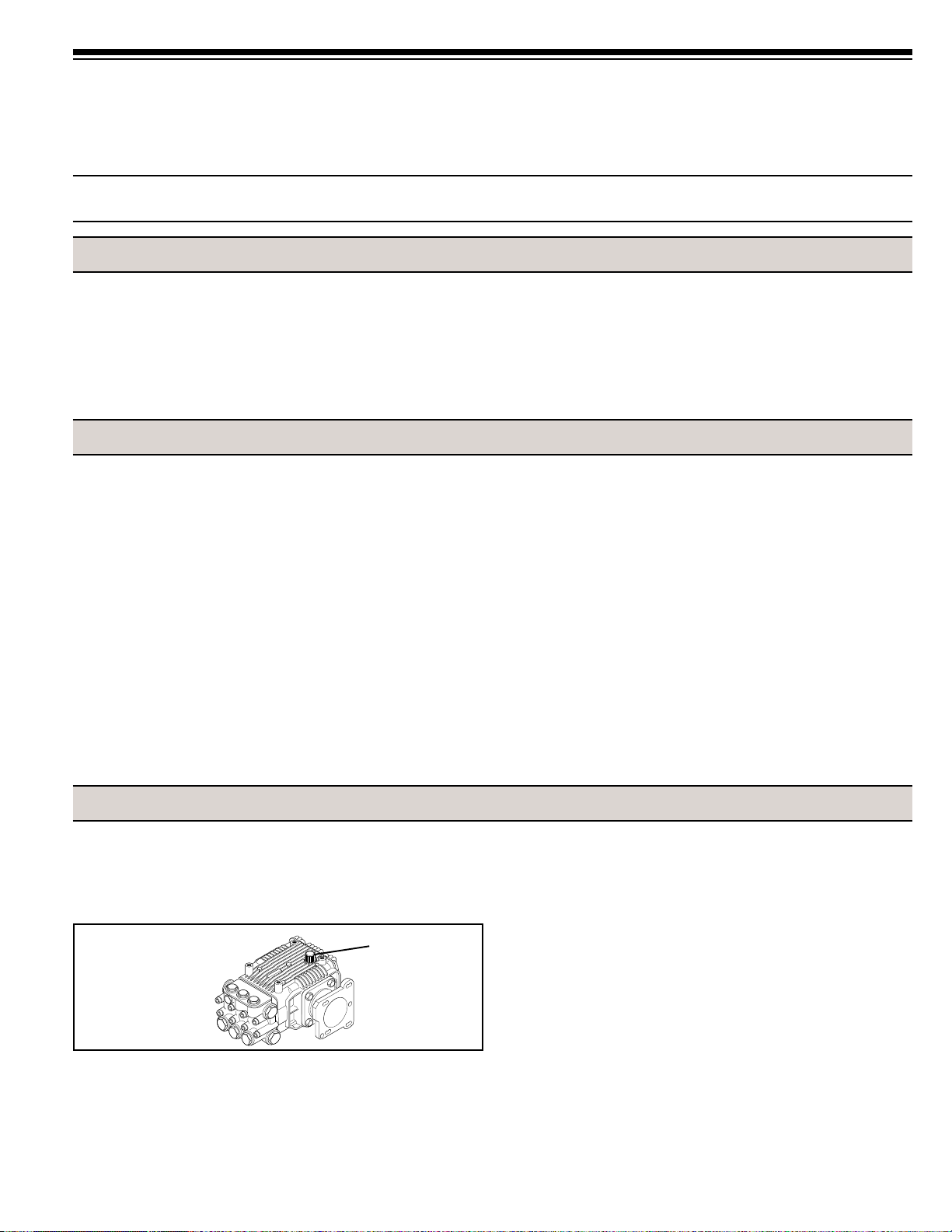
• Check that the oil is at the correct level using the Dipstick,
topping off if necessary (See Figure 1). Use a nondetergent,
SAE 30 weight oil.
Dipstick
FIGURE 1
Dipstick Location
• Change oil after 40 hours of break-in operation. Thereafter,
change the oil every year or 500 hours, whichever comes first.
NOTE: During warm months keep the power Washer Pump
filled with water and the Outlet Pressure Hose and Gun
Assembly attached. For storage during freezing conditions,
flush the Pump with the specified John Deere Winterizing
Fluid, N209391-CA (Canada) or N209318-US (U.S.). Leave this
fluid in the Pump with the Outlet pressure hose and Gun
attached.
• Release all pressure within the system before servicing any
component.
• The high-pressure gun and lance should be securely held by
hand or in a holding device before the unit is started. Make sure
the lance is not pointed toward any person or animal. Failure to
do so could result in serious injury.
• Periodically inspect the pump and the system components.
Perform routine maintenance as required (see Repair Section).
• Do not use these pumps for pumping water or other liquids for
human or animal consumption.
During Bypass Operation
• When the water is diverted back to the pump inlet side, a
temperature rise occurs. A thermal relief is included to keep the
water temperature at a maximum of 145
o
F.
Unloader Valve Safety Information
• Maximum pressure is set at the factory and cannot be adjusted to
a higher pressure.
• Do not tamper with the unloader valve settings or with the locking
ring; doing so will void the warranty. Damage to the pressure
washer may result.
WARNING: Water discharged from the thermal relief valve is
hot (145
o
F).
Page 2

Operation
1. Check the water level in the rinse tank. Never operate the
Pressure Wash Pump without a water supply.
NOTE: Periodically check the Line Strainer and clean the Line
Strainer if it is necessary (See Figure 2).
2. Open the water supply valve.
CAUTION: Do not operate any other hydraulic functions on the
4700 while the Power Washer is in use.
3. Set the engine speed to 1,500 RPM.
4. Activate the Hydraulic Motor by placing the Lever on the
Hydraulic Control Valve in the DOWN position (See Figure 3).
5. Point the Spray Gun at the target area and squeeze the Spray
Gun Trigger (See Figure 4).
6. The standard Power Washer is equipped with an adjustable
cleaning angle nozzle. The cleaning angle may be varied
throughout its range by rotating the black outer body clockwise
(CW) or counterclockwise (CCW).
7. If your Power Washer is equipped with the optional Detergent
Injection System. The nozzle must be set in Low Pressure
Mode to activate the injector and draw soap. For rinsing, the
nozzle should be set in High pressure Mode. Pushing the black
nozzle body forward places the nozzle in the Low Pressure
Mode. Pulling the black nozzle body back places the nozzle in
the High Pressure Mode.
NOTE: When finished using the Power Washer, make sure the
Power Washer is shut off (Hydraulic Control Valve lever in the
UP position) before operating other hydraulic functions on the
4700 (See Figure 5).
8. Store all the Power Washer components in brackets provided
for their storage.
Pump Strainer
FIGURE 2
Hydraulic
Control
Valve
Lever
FIGURE 3
FIGURE 4
Hydraulic
Control
Valve
Lever
FIGURE 5
Troubleshooting
SYMPTOM PROBABLE CAUSE(S) CORRECTIVE ACTION
The pump runs but Pump is not primed. Open water supply valve and fill rinse tank.
produces no flow.
Pump fails to prime. Air is trapped in pump. Squeeze and release trigger several times. If pump still does
Low pressure at nozzle. Pump is partially primed. Repeat steps from above .
Air leak in suction hose or pump Make sure all the inlet fittings are tight and not leaking.
inlet fittings.
Partially clogged strainer. Unscrew strainer bowl and clean screen.
Pump loses prime, Air leak in suction hose or pump Make sure all the inlet fittings are tight and not leaking.
pressure fluctuates, and/ inlet fittings.
or pump makes Partially clogged strainer. Unscrew strainer bowl and clean screen.
chattering noise.
Rapid cycling of pressure Water leakage down stream from Check for leaks in discharge pressure hose, pipe fittings,
when gun trigger is unloader valve. gun wand, and nozzle assembly.
closed.
4700 Sprayer operation Lever on Hydraulic Control Valve Shut Power Washer OFF by returning Control Lever up to the
is unusually slow. is in the DOWN position and OFF position
the Power Washer is running.
Hydraulic Motor Oil Backward plumbing of hydraulics. Verify proper plumbing of hydraulics to Motor; Motor Supply Hose to
Seal leaks. "PRESS" port and Return Hose to "TANK" port.
If the Power Washer is used and/or not maintained properly, it may be necessary to service the pump and/or
Unloader Valve. Refer to the proper Sections in this manual for servicing instructions.
not prime, disconnect the discharge hose and run until air is
evacuated, then reattach the discharge hose.
- 2 -
Page 3
Pump Repair Instructions
PACKING REPLACEMENT
PMKIT2747 and PMKIT2745
1. Water leakage between the Head and the Crankcase indicates
the Plunger Packings require replacement.
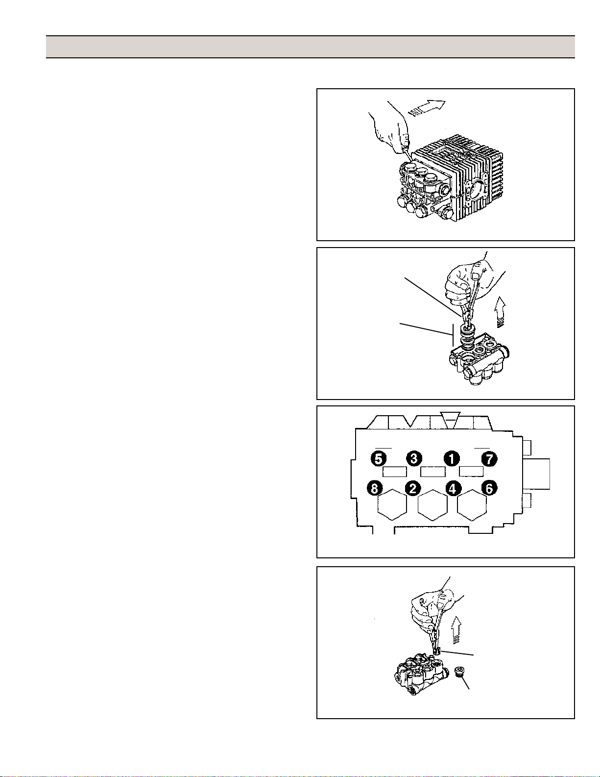
2. Use a Hex wrench to remove the Head Bolts; then, remove the
Head from the Crankcase by rotating the Crankshaft while using
a screwdriver to carefully pry between the Head and the
Crankcase (See Figure 6).
3. After the Head has been removed, use an Extractor Pliers
to remove the Plunger Seal Retainers, and Packings (See
Figure 7).
4. Using a small bladed screwdriver, remove the Low Pressure
Packing from the Retainer.
5. Insert a Low Pressure Packing into the Retainer by forming the
Seal into a kidney or oval shape; then, work the Seal into place
in the Retainer.
6. Apply a thin film of oil the Retainer O-ring; then, replace the
Retainer O-ring.
7. Apply a thin film of oil to all Seals; then, place the High Pressure
Packing and Cup Spreader into the head bore.
8. Place the Brass Packing Retainer into the Head and push the
Retainer in until the Retainer O-ring is sealed in the Head.
9. Check the Plungers for damage or cracking (refer to Plunger
Replacement section).
10. Repeat Steps 5 through 8 for the rest of the Cylinders.
11. Lightly oil the Plungers and install the Head onto the Plungers.
12. Push the head against the Crankcase; then, secure the Head to
the Crankcase with the Head Bolts.
13. Tighten the Head Bolts to 88 in lbs. torque, in the sequence
shown (See Figure 8).
FIGURE 6
Extractor Pliers
Plunger Seal
Retainers, and
Packing
FIGURE 7
VALVE REPLACEMENT
PM34300424
1. Erratic or low pressure operation may be caused by debris or
foreign material in the Valves or worn Poppets or a combination
of worn Poppets and/or Seats.
2. Remove the Valve Caps; then, using a needle-nosed plier, pull
out the Valve Assembly (See Figure 9).
3. Inspect the Valve for debris or foreign material and signs of wear.
If the Valve is worn or damaged, replace the Valves and the
valve O-rings.
4. Install the new Valve Assemblies; then, install the Valve Caps
and tighten them to 25 ft lbs. torque.
FIGURE 8
Valve
Assembly
Valve Cap
FIGURE 9
- 3 -
Page 4
PLUNGER REPLACEMENT
PMKIT2746
1. If damage to the Plungers is noted during Packing Replacement,
continue with Plunger Replacement.
2. Remove the Pump Head from the Crankcase as described in
PACKING REPLACEMENT.
3. Remove the Plunger Retaining Nut and the Plunger Retaining
Nut Washer; then, carefully slide the Plunger off the Lower
Plunger (See Figure 10).
4. Remove and discard the old O-ring and Slinger Ring from the
Lower Plunger (See Figure 10).
5. Install the new Slinger onto the loser Plunger.
6. Apply a thin film of oil to the Lower Plunger; then, install the new
O-ring.
7. Slide the Plunger onto the Lower Plunger.
8. Apply a drop of blue anaerobic thread locking compound to the
Plunger Retaining Nut; then, install the Plunger Retaining Nut
and Washer onto the Lower Plunger.
O-ring
&
Slinger Ring
FIGURE 10
Plunger
Lock
Washer
Plunger
Retaining Nut
9. Tighten the Plunger Nut to 88 in lbs.
10. Install the new Plunger Packings as described in PACKING
REPLACEMENT.
Hydraulic Motor Repair Instructions
HYDRAULIC MOTOR DISASSEMBLY
CAUTION: Dirt and other contaminants can damage hydraulic
motor components. Always maintain a clean work area when
working with hydraulic motors or components.
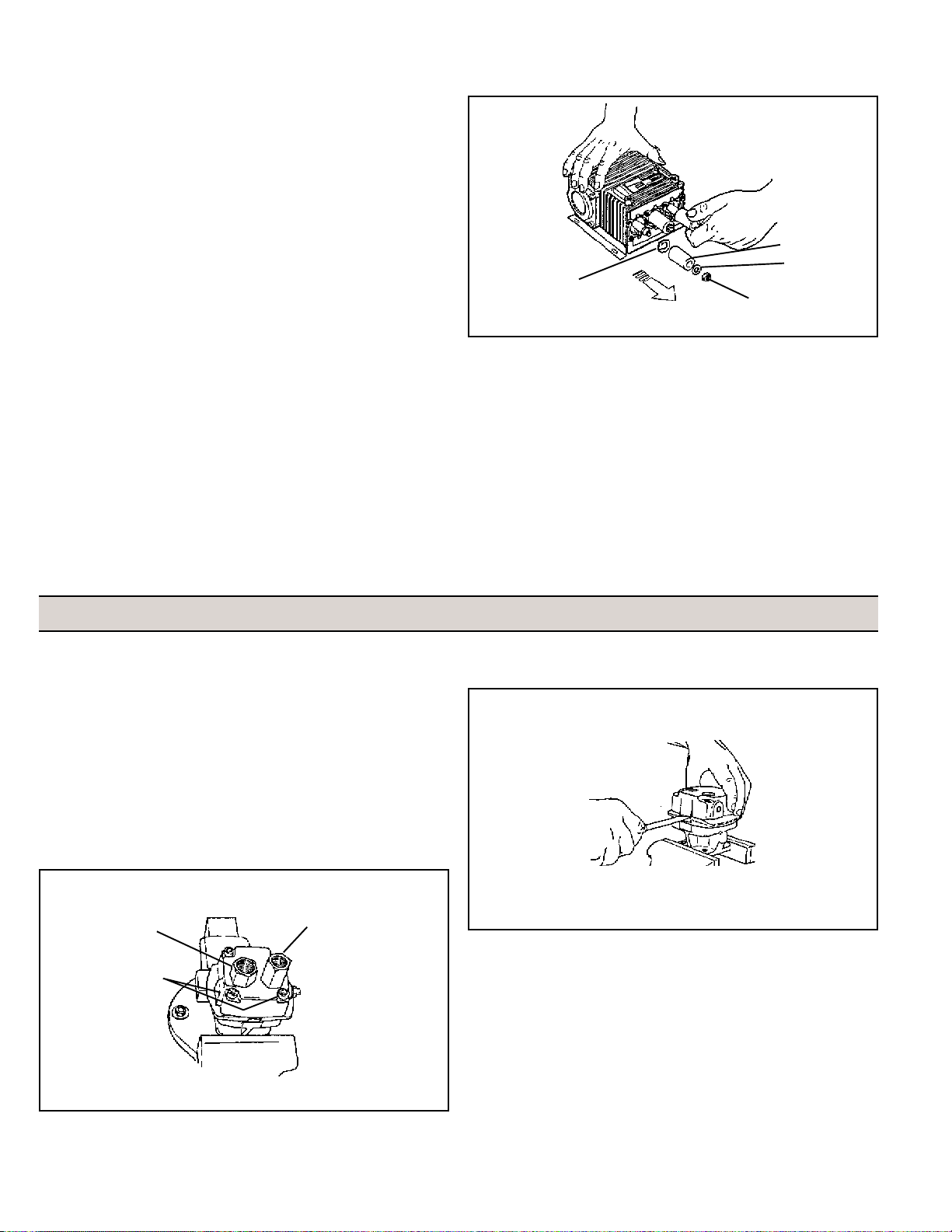
1. Place the Hydraulic Motor in a vise (See Figure 11).
2. Using a 1-1/16’’ Box wrench, remove the Tank Port Adapter and
Pressure Port Adapter (See Figure 11).
3. Using a 1/4’’ Hex wrench, remove the Socket Head Cap Screws
from the Motor End Plate (See Figure 11).
Pressure Port
Adapter
Socket Head
Cap Screws
Tank Port
Adapter
FIGURE 12
4. Remove bottom parts of the Gerotor.
5. Remove and save the Shaft Key.
6. Remove and discard the old O-ring from the Motor End Plate and
Body.
FIGURE 11
NOTE: If the Motor End Plate will not lift off easily, use a small
screwdriver to carefully pry apart the boss portion of the End
Plate and Gerotor Housing (See Figure 12). If the Gerotor
Housing will not easily lift off, carefully pry apart the boss area
between the Gerotor Housing and the Motor Body.
7. Inspect the Motor End Plate, Body, and Gerotor Housing for
signs of wear or gouging. If wear or gouging has occurred in both
the Motor End Plate, and Body, these components must be
replaced. If the Gerotor Housing is damaged, the Gerotor parts
must also be replaced.
8. While the Motor is disassembled, clean all components in an
approved part cleaning solvent.
- 4 -
Page 5

REMOVING THE SHAFT ASSEMBLY FROM THE
MOTOR BODY
1. Remove the Slinger Ring from the Motor Shaft.
WARNING: Always wear safety goggles when working with
spring or tension loaded fasteners or devices.
2. Remove the Retaining Ring next to the Ball Bearing in the Front
Motor Body.
NOTE: If the Bearing is binding against the Retaining Ring
preventing easy removal of the Retaining Ring, slide a 1''
diameter section of pipe over the Shaft; then, gently press
down with an Arbor Press to relieve the pressure on the
Retaining Ring.
3. Place the Motor Body in a Support Fixture with the threaded
portion of the Shaft inside the Support Fixture; then, using an
Arbor Press, press the Shaft Assembly out of the Motor Body
(See Figure 13).
Motor Body
Shaft
Assembly
Support
Fixture
5. Thread the Impeller Nut on the end of the Shaft; then, using an
Arbor Press; press the Shaft through the Bearing, Seal Spacer,
and Seal (See Figure 14).
6. Inspect the sealing area of the Shaft and other components for
wear and replace then if necessary.
INSTALLING THE NEW SHAFT SEAL
1. The sealing lips on a new Seal must be expanded to fit on the
Shaft. Press the Seal onto the large end of the Shaft with the
Seal Lip facing out. Do not push the Seal past the Shaft keyway.
2. Remove the Seal from the Shaft after the seal lip has been
expanded.
3. With the seal lip facing the large end of the Shaft, slide the Seal
over the threaded end of the Shaft; then, gently push it onto the
raised area of the Shaft, stopping approximately 1/4'' from the
large retaining ring groove.
WARNING: Always wear safety goggles when working with
spring or tension loaded fasteners or devices.
4. Install the Seal Spacer, Thrust Bearing Race, Thrust Bearing,
second Thrust Bearing Race, and the large Retaining Ring over
the threaded end of the Shaft.
INSTALLING THE SHAFT BEARING
FIGURE 13
HYDRAULIC MOTOR SHAFT DISASSEMBLY
WARNING: Always wear safety goggles when working with
spring or tension loaded fasteners or devices.
1. Remove the Large Retaining Ring from the Shaft.
2. Remove the Thrust Bearing Assembly (includes the Thrust
Bearing and two Thrust Bearing Races) from the Shaft and the
Seal Spacer.
3. Remove the Small Retaining Ring next to the Shaft Ball Bearing.
4. Place the Shaft (threaded end up) in a pipe support fixture; then,
place the two Support Bars included in the repair kit opposite
each other and between the Seal on the Shaft and the support
fixture (See Figure 14).
1. Install the Spacer Ring, and Ball Bearing over the threaded
end of the Shaft.
2. Insert the Shaft (threaded end down) into the Support Fixture.
3. Place the two support bars opposite each other and between
the Bearing and the Fixture; then, using an Arbor Press,
carefully press the Shaft down, but allowing enough room for
the Retaining Ring next to the Bearing to be installed.
CAUTION: The Spacer Ring between the Seal and Bearing must
be free floating, not binding.
4. Place the Shaft Assembly into the Motor Body Bearing Bore with
the threaded end facing up (See Figure 15).
FIGURE 14
FIGURE 15
- 5 -
Page 6

NOTE: A fixture is required for the next Step; fabricate this
fixture from a 1'' diameter by 4'' long section of PVC pipe. When
using this fixture make sure all surfaces are clean and the
support edges are smooth.
5. Place the fixture over the Shaft and using an Arbor Press, press
the Shaft Assembly down until the Retaining Rings can be
installed in its groove in the bearing bore of the Motor Body.
WARNING: Always wear safety goggles when working with
spring or tension loaded fasteners or devices.
7. Apply a thin film of oil to the O-ring and install it on the Motor End
Plate.
8. Place the End Plate on the Gerotor Housing, making sure the
holes in the End Plate line up with the Pins in the Gerotor
Housing.
10. Apply a drop of blue anaerobic thread locking compound to the
threads of the four Socket Head Cap Screws; then, using the
four Socket Head Cap Screws, secure the Motor End Plate to the
Gerotor Housing.
6. Install the Retaining Ring into the groove of the Bearing Bore.
HYDRAULIC MOTOR FINAL ASSEMBLY
1. Place the Motor Body in a vise with the large end of the Shaft
facing up.
2. Apply a thin film of oil to the O-ring; then, install the O-ring in the
Motor Body.
3. Install the Woodruff key or Roll Pin on the Shaft; then, place the
Inner Gear onto the Shaft, making sure the Gerotor slot lines up
with the Key in the Shaft.
4. Install the outer portion of the Gerotor, making sure the Gerotor
is centered within the o-ring groove on the Body.
5. Install the Gerotor housing, making sure the pins in the Gerotor
Housing line up with their respective holes in the Body.
6. Apply a thin coating of hydraulic or mineral oil to the area
between the Inner and outer Gerotor, the Outer Gerotor, and the
Gerotor Housing.
Replacement Parts
11. Alternately and evenly, tighten the four Socket Head Cap
Screws to 15 ft lbs. torque.
12. Install a new O-ring in both Port Adapters.
13. Install the Pressure Port Adapter onto the Motor; then, install the
Tank Port Adapter onto the Motor.
14. Remove the Hydraulic Motor from the vise and rotate the Shaft
by hand to check for binding of the Shaft.
15. Install a Slinger ring over the Motor shaft.
16. Apply a drop of blue anaerobic thread locking compound to the
threads of the four Hex Head Bolts; then, using the four Hex
Head Bolts, secure the Motor into the pump Mounting Flange.
17. Alternately and evenly, tighten the four Hex Head Bolts.
To 4700 Hydraulic load
Sensor
PM34300553
To 4700 Hydraulic
Supply
PM34300565
TO 4700 Hydraulic
Return
PM34300555
FIGURE 16
Replacement Components
Control Valve
PM34300552
Complete Motor
PM25000020C1
Motor Supply
PM34300554
Complete Pump
PMXMA4G20ESX
-6-
Bracket & Hardware Kits:
Gun & lance Bracket hardware PM34300561
Pump Mounting Bracket PM34300556
Detergent Injection
See Options (Page 10)
High Pressure Hose
See Options (Page 10)
Unloader
PM339001042B
PM34300557
To Rinse Tank
Page 7

Complete Pump
Part No. PMXMA4G20ESX
1
FIGURE 17
Service Parts for Pressure Pump
10
11
7
6
4
8
5
3
2
9
Piston Kit PMKIT2746
Ref. Description Qty.
8 Piston 3
Valve Kit PM34300424
Ref. Description Qty.
1 Complete Valve 6
2 O-ring 6
Water Seal Kit PMKIT2747
Ref. Description Qty.
4 Gasket 3
6 O-ring 3
5 Gasket 3
Lance
PM3365000436
Oil Seal Kit PMKIT2787
Ref. Description Qty.
10 Cap 1
11 O-ring 1
9 Seal 1
7 Seal 3
Cup Spreader Kit PMKIT2745
Ref. Description Qty.
3 Support Ring 3
Nozzle
PM332420015
Gun
PM33810032
FIGURE 18
Gun, Lance, and Nozzle, Replacement Components
Replacement Hose
Order direct by calling:
1-877-535-5336
Part No. 851-0007
- 7 -
Page 8

Complete Motor
PM25000020C1
6
4
7
8
7
5
1
3
2
FIGURE 19
Service Parts for Hydraulic Motor
Motor Kit PM
Ref. Description Part No. Qty.
1 Retaining Ring PM18100014 1
2 Ball Bearing PM20000010 1
3 Shaft Seal PM21040005 1
4 Thrust Bearing Assembly PM20290014 1
5 Shaft PM05132500 1
6 Key PM16100012 1
7 O-ring PM17200110 2
8 Gerotor PM39000024 1
Unloader Kit PM34300484
Ref. Description Qty.
1 Washer 1
2 O-ring 1
3 O-ring 1
4 O-ring 1
5 Washer 1
6 O-ring 1
7 O-ring 1
8 Valve Seat 1
9 O-ring 1
10 Piston 1
11 Spring 1
12 O-ring 1
13 O-ring 1
1
2
3
4
5
6
Complete Unloader Valve
PM339001042B
7
8
FIGURE 20
Service Parts for Unloader
- 8 -
9
10
11
12
13
Page 9

Hose Reel (PM34300560)
Optional Equipment
Includes:
Reel
Hardware
Jumper Hose
Hose Wrap (PM34300563)
Includes:
Wrap Bracket
Hardware
FIGURE 21
Hose Reel (PM34300560)
FIGURE 22
Hose Wrap (PM34300563)
Detergent Injection Kit (PM34300562)
Includes: Detergent
Attachment Bracket
Hardware
Tube
Strainer
Detergent
One Gallon: U.S. - N209615
Canada - N209616
FIGURE 23
Detergent Injection Kit (PM34300562)
FIGURE 24
Detergent
- 9 -
Page 10

NOTES
- 10 -
Page 11

NOTES
- 11 -
Page 12

Printed in U.S.A.
01/2000
Deere & Company
One John Deere Place
Moline, Illinois 61265
- 12 -
 Loading...