

Page 1

John Deere Machine
*DCY*
*OMPFP12436*
Communication Radio
OPERATOR'S MANUAL
John Deere Machine Communication
Radio
OMPFP12436 ISSUE E2 (ENGLISH)
*OMPFP12436*
CALIFORNIA
Proposition 65 Warning
Diesel engine exhaust and some of its constituents
are known to the State of California to cause cancer,
birth defects, and other reproductive harm.
If this product contains a gasoline engine:
WARNING
The engine exhaust from this product contains
chemicals known to the State of California to cause
cancer, birth defects or other reproductive harm.
The State of California requires the above two warnings.
Additional Proposition 65 Warnings can be found in this manual.
John Deere Ag Management Solutions
LITHO IN THE USA
Page 2

Introduction
www.StellarSupport.com
NOTE: Product functionality may not be fully represented in this document due to product changes occurring after the time of printing. Read the
latest Operator's Manual and Quick Reference Guide prior to operation. To obtain a copy, see your dealer or visit www.StellarSupport.com
OUO6050,0000FB1 -19-10AUG10-1/1
Read This Manual
Before operating display/software, familiarize yourself
with components and procedures required for safe
and proper operation.
IMPORTANT: The following GreenStar components
are not weather-proof and should only be used
on vehicles equipped with a cab. Improper
use may void warranty.
Original GreenStar Display and Mobile
•
Processor
GreenStar Displays
•
AutoTrac Universal Steering Kit
•
John Deere Machine Communication Radio
•
JS56696,000094C -19-12DEC11-1/1
052912
PN=2
Page 3

Contents
Page
Safety
Recognize Safety Information ............................ 05-1
Understand Signal Words...................................05-1
Follow Safety Instructions...................................05-1
Practice Safe Maintenance.................................05-2
Handle Electronic Components and
Brackets Safely .............................................. 05-2
Avoid Electrical Power Lines ..............................05-3
Regulatory Notications to User
Information to User.............................................10-1
United States ......................................................10-1
Canada...............................................................10-1
European Community.........................................10-1
System Overview
Theory of Operation............................................15-1
Components .......................................................15-1
Conguring Radio
Create Network...................................................20-1
Set My Name on Network...................................20-7
Verify Network Functionality ...............................20-9
Reprogram Radio
Update Radio Software ...................................... 25-1
Network Information
Network Tab........................................................ 30-1
Network Diagnostics...........................................30-2
Troubleshooting
Radio Troubleshooting .......................................35-1
Cap Antenna Connections..................................35-2
Specications
Radio Specications ...........................................40-1
EC Declaration of Conformity ............................. 40-1
Original Instructions. All information, illustrations and specications in this
manual are based on the latest information available at the time of publication.
The right is reserved to make changes at any time without notice.
COPYRIGHT © 2012
DEERE & COMPANY
Moline, Illinois
A John Deere ILLUSTRUCTION ® Manual
All rights reserved.
i
052912
PN=1
Page 4

Contents
ii
052912
PN=2
Page 5

Safety
Recognize Safety Information
This is a safety-alert symbol. When you see this symbol
on your machine or in this manual, be alert to the potential
for personal injury.
Follow recommended precautions and safe operating
practices.
Understand Signal Words
A signal word—DANGER, WARNING, or CAUTION—is
used with the safety-alert symbol. DANGER identies the
most serious hazards.
DANGER or WARNING safety signs are located near
specic hazards. General precautions are listed on
CAUTION safety signs. CAUTION also calls attention to
safety messages in this manual.
T81389 —UN—07DEC88
DX,ALERT -19-29SEP98-1/1
Follow Safety Instructions
Carefully read all safety messages in this manual and on
your machine safety signs. Keep safety signs in good
condition. Replace missing or damaged safety signs. Be
sure new equipment components and repair parts include
the current safety signs. Replacement safety signs are
available from your John Deere dealer.
There can be additional safety information contained on
parts and components sourced from suppliers that is not
reproduced in this operator's manual.
Learn how to operate the machine and how to use controls
properly. Do not let anyone operate without instruction.
Keep your machine in proper working condition.
Unauthorized modications to the machine may impair the
function and/or safety and affect machine life.
TS187 —19—30SEP88
DX,SIGNAL -19-03MAR93-1/1
TS201 —UN—23AUG88
If you do not understand any part of this manual and need
assistance, contact your John Deere dealer.
DX,READ -19-16JUN09-1/1
05-1
052912
PN=5
Page 6

Safety
Practice Safe Maintenance
Understand service procedure before doing work. Keep
area clean and dry.
Never lubricate, service, or adjust machine while it is
moving. Keep hands, feet , and clothing from power-driven
parts. Disengage all power and operate controls to relieve
pressure. Lower equipment to the ground. Stop the
engine. Remove the key. Allow machine to cool.
Securely support any machine elements that must be
raised for service work.
Keep all parts in good condition and properly installed.
Fix damage immediately. Replace worn or broken parts.
Remove any buildup of grease, oil, or debris.
On self-propelled equipment, disconnect battery ground
cable (-) before making adjustments on electrical systems
or welding on machine.
On towed implements, disconnect wiring harnesses from
tractor before servicing electrical system components or
welding on machine.
Handle Electronic Components and Brackets Safely
Falling while installing or removing electronic components
mounted on equipment can cause serious injury. Use a
ladder or platform to easily reach each mounting location.
Use sturdy and secure footholds and handholds. Do not
install or remove components in wet or icy conditions.
If installing or servicing a RTK base station on a tower or
other tall structure, use a certied climber.
If installing or servicing a global positioning receiver mast
used on an implement, use proper lifting techniques and
wear proper protective equipment. The mast is heavy and
can be awkward to handle. Two people are required when
mounting locations are not accessible from the ground
or from a service platform.
TS218 —UN—23AUG88
DX,SERV -19-17FEB99-1/1
TS249 —UN—23AUG88
DX,WW,RECEIVER -19-24AUG10-1/1
05-2
052912
PN=6
Page 7

Avoid Electrical Power Lines
Avoid all low-hanging electrical lines while operating the
machine.
On some machines, the antenna may be high enough to
come in contact with low-hanging electrical lines. This can
result in severe electrical shock to the operator.
Safety
PC13658 —UN—08NOV11
JS56696,0000A60 -19-15NOV11-1/1
05-3
052912
PN=7
Page 8

Regulatory Notications to User
Information to User
This device must be operated as supplied by John Deere
Ag Management Solutions. Any changes or modications
made to these devices without the express written
United States
This device complies with FCC Part 15. Operation is
subject to the following two conditions:
(1) This device may not cause harmful interference, and
(2) This device must accept any interference, including
interference that may cause undesired operation of the
device.
This equipment has been tested and found to comply with
the limits for a Class A digital device, pursuant to Part 15
of the FCC Rules. These limits are designed to provide
reasonable protection against harmful interference
when the equipment is operated in a commercial
Canada
This device complies with Industry Canada license-exempt
RSS standard(s). Operation is subject to the following
two conditions:
(1) This device may not cause harmful interference, and
(2) This device must accept any interference, including
interference that may cause undesired operation of the
device.
This device has been designated to operate with the
antenna(s) listed below, and having a maximum gain of
5 dBi. Antennas not included in this list or having a gain
greater than 5 dBi are strictly prohibited for use with this
device. The required antenna impedance is 50 Ohms.
approval of John Deere Ag Management Solutions may
void the user’s authority to operate this device.
CZ76372,00003A2 -19-12DEC11-1/1
environment. This equipment generates, uses, and can
radiate radio frequency energy and, if not installed and
used in accordance with the instruction manual, may cause
harmful interference to radio communications. Operation
of this equipment in a residential area is likely to cause
harmful interference in which case the user will be
required to correct the interference at their own expense.
This device has been found to be compliant to the
requirements set forth in CFR 47 Sections 2.1091,
and 15.247 (b) (4) addressing RF Exposure from radio
frequency devices as dened in Evaluating Compliance
with FCC Guidelines for Human Exposure to Radio
Frequency Electromagnetic Fields.
CZ76372,00003A3 -19-12DEC11-1/1
Antenna part number = PFP11422
This Class A digital apparatus meets all the requirements
of the Canadian Interference-Causing Equipment
Regulations.
This device complies with Health Canada’s Safety Code 6
/ IC RSS-210. The installer of this device should ensure
that RF radiation is not emitted in excess of the Health
Canada’s requirement.
Information can be obtained at: http://www.hcsc.gc.ca/ewh-semt/pubs/radiation/radio_guidelignes_direct-eng.php
CZ76372,00003A4 -19-12DEC11-1/1
European Community
This equipment operates in the 2402 to 2472 MHz
frequency range. Check with local authorities for the latest
status of national regulations for the 2.4 GHz wireless
bands. National regulations may require that operations
be limited to portions of the frequency ranges identied
above.
France
Do NOT operate the Machine Communication Radio on
Channel C in France. Only use Channels A and B in
France.
10-1
PC13686 —UN—13DEC11
In France, the output power is restricted to 10 mW EIRP
when the product is used outdoors in the 2454-2483.5
MHz band. This restriction only impacts Channel
9 (Channel C). It does not affect Channel 1 (Channel A)
and Channel 5 (Channel B).
CZ76372,00004C3 -19-21MAY12-1/1
052912
PN=8
Page 9

System Overview
Theory of Operation
The John Deere Machine Communications Radio is a
2.4GHz radio which provides networking capability to
machines located in a eld. At least two radios, or nodes,
Components
Radio
A—Power/Data (Ethernet)
B—Antenna (Coax)
C—LED
are required within range of each other to form a network.
Additional nodes may spontaneously join or drop out
without disrupting the network architecture.
CZ76372,00003A6 -19-12DEC11-1/1
PC14281 —UN—05DEC11
CZ76372,00003A7 -19-12DEC11-1/2
Antenna
A—Antenna
B—Coax Connector
PC13668 —UN—08DEC11
CZ76372,00003A7 -19-12DEC11-2/2
15-1
052912
PN=9
Page 10

Conguring Radio
Create Network
1. Ensure that Power/Data cable is properly installed
(A). The LED (C) on radio will be green when radio
has power.
NOTE: MCR LED will blink until a network connection
has been established.
A—Power/Data (Ethernet)
B—Antenna (Coax)
C—LED
2. On GS3 display, press Menu button and select GS3
button.
3. Select Equipment softkey on the right side of main
menu.
PC14281 —UN—05DEC11
CZ76372,00003A8 -19-12DEC11-1/10
PC8663 —UN—05AUG05
MENU button
PC12685 —UN—14JUL10
GREENSTAR 3 PRO button
PC8677 —UN—05AUG05
EQUIPMENT softkey
Continued on next page CZ76372,00003A8 -19-12DEC11-2/10
20-1
052912
PN=10
Page 11

4. From Equipment screen, select Network tab.
A—Network Tab
Conguring Radio
PC14286 —UN—06DEC11
CZ76372,00003A8 -19-12DEC11-3/10
5. Select View Networks.
A—View Networks
PC14287 —UN—06DEC11
Continued on next page CZ76372,00003A8 -19-12DEC11-4/10
20-2
052912
PN=11
Page 12

6. Select Manage Networks button.
A—Manage Networks
Conguring Radio
PC14288 —UN—06DEC11
CZ76372,00003A8 -19-12DEC11-5/10
7. Select Add New on manage networks screen.
A—Add New
PC14289 —UN—06DEC11
Continued on next page CZ76372,00003A8 -19-12DEC11-6/10
20-3
052912
PN=12
Page 13

Conguring Radio
8. Select Network Name box and use keyboard to type
name of new network. Once network name is entered
press Accept button.
NOTE: Network Name must be 6-20 characters in length
and can contain lower case letters (a-z), numbers
(0-9), spaces, hyphens or dashes, and underscores.
9. Select a Channel on Edit Network Information screen
NOTE: For more details regarding channel selection
see the Radio Specications section.
A—Network Name
B—Channel
C—Accept Button
D—Keyboard
E—Keyboard Accept Button
PC14290 —UN—06DEC11PC14291 —UN—06DEC11
Continued on next page CZ76372,00003A8 -19-12DEC11-7/10
20-4
052912
PN=13
Page 14

10. Select Accept button once Network Name and
Channel are set. The new network now exists on
Manage Networks screen.
Conguring Radio
A—Network Name
B—Channel
C—Accept
11. Select Accept button on the Manage Networks screen.
The new network now exists on View Networks screen.
A—Accept
PC14292 —UN—06DEC11
CZ76372,00003A8 -19-12DEC11-8/10
Continued on next page CZ76372,00003A8 -19-12DEC11-9/10
20-5
PC14293 —UN—06DEC11
052912
PN=14
Page 15
Conguring Radio
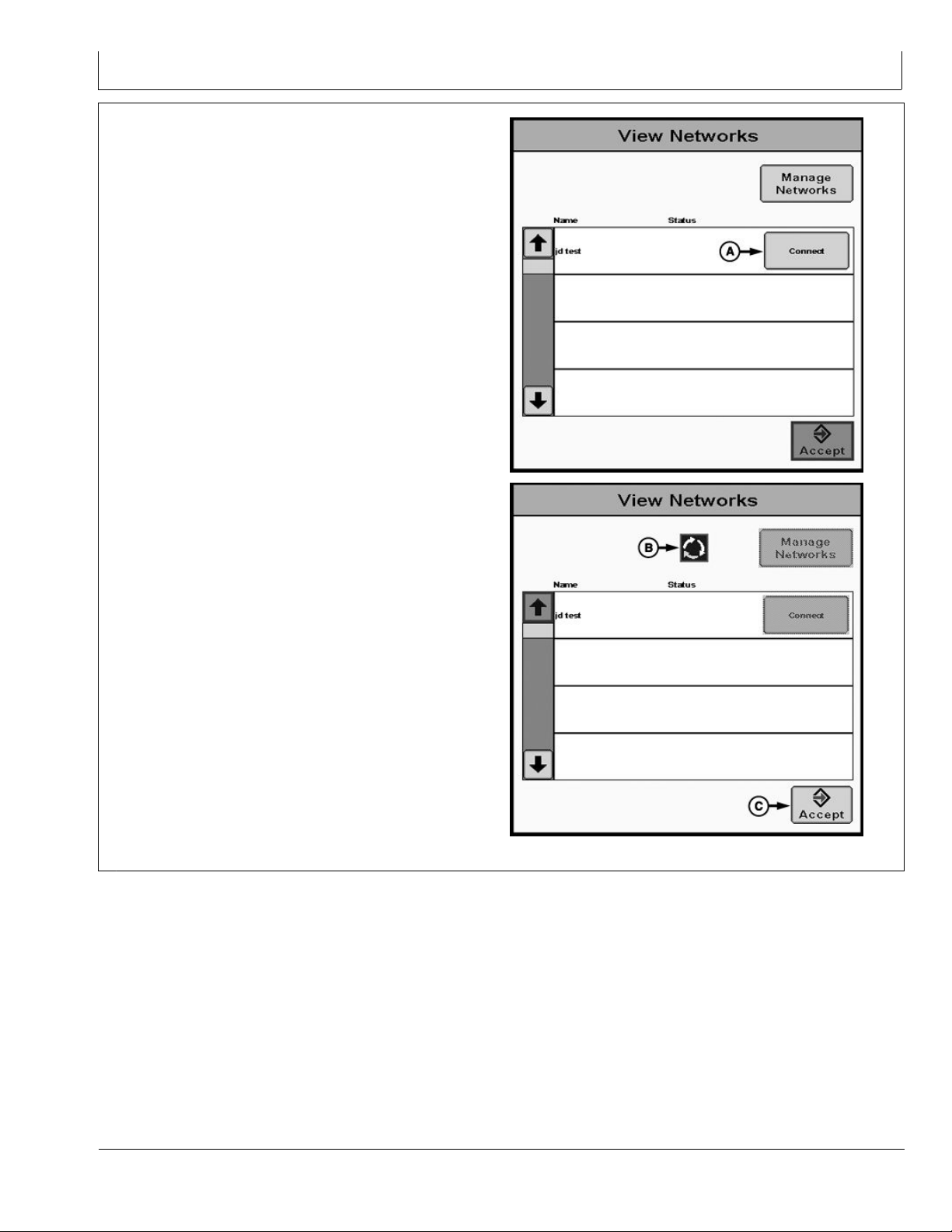
12. Next to the network name, select Connect button to
join. A status symbol with three arrows in a circular
formation will appear. This can take up to 90 seconds
to complete. Press Accept button to return to Network
tab during (or after) this time.
NOTE: While connecting, Data Transfer (Import/Export
Data) feature is disabled.
NOTE: Each display must add each network to its
network list. To add this network to another node,
or to add another network to network list, repeat
previous steps in this process. Every vehicle in
network must Connect to same network, even if
there is no one else in network yet.
A—Connect
B—Status
C—Accept Button
PC14300 —UN—06DEC11PC14295 —UN—06DEC11
20-6
CZ76372,00003A8 -19-12DEC11-10/10
052912
PN=15
Page 16
Conguring Radio
Set My Name on Network
My Name on Network is the name for this vehicle on other
vehicles’ displays. This name is shown on the ‘Others in
Network’ list and in the On-Screen maps.
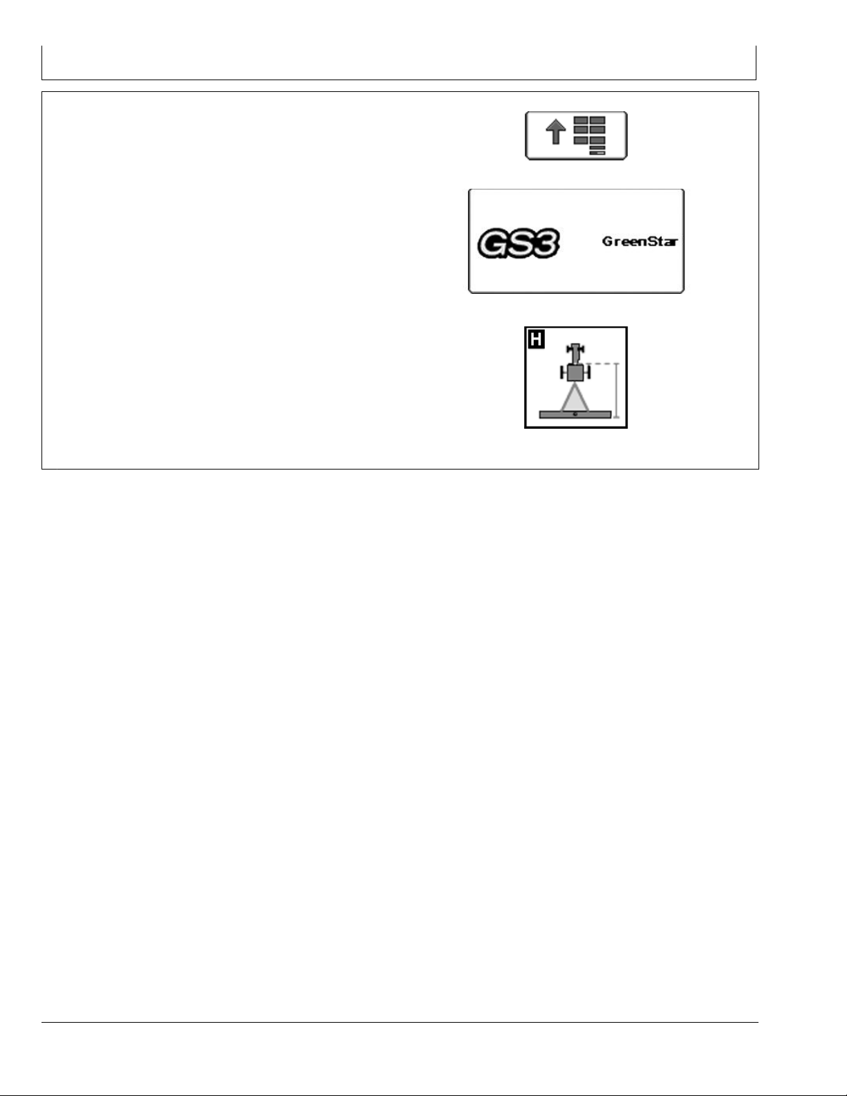
1. Select Menu button and select GS3 button.
2. Select Equipment softkey on the right side of main
menu.
PC8663 —UN—05AUG05
PC12685 —UN—14JUL10
PC8677 —UN—05AUG05
Continued on next page CZ76372,00003A9 -19-12DEC11-1/2
MENU button
GREENSTAR 3 PRO button
EQUIPMENT softkey
20-7
052912
PN=16
Page 17
Conguring Radio
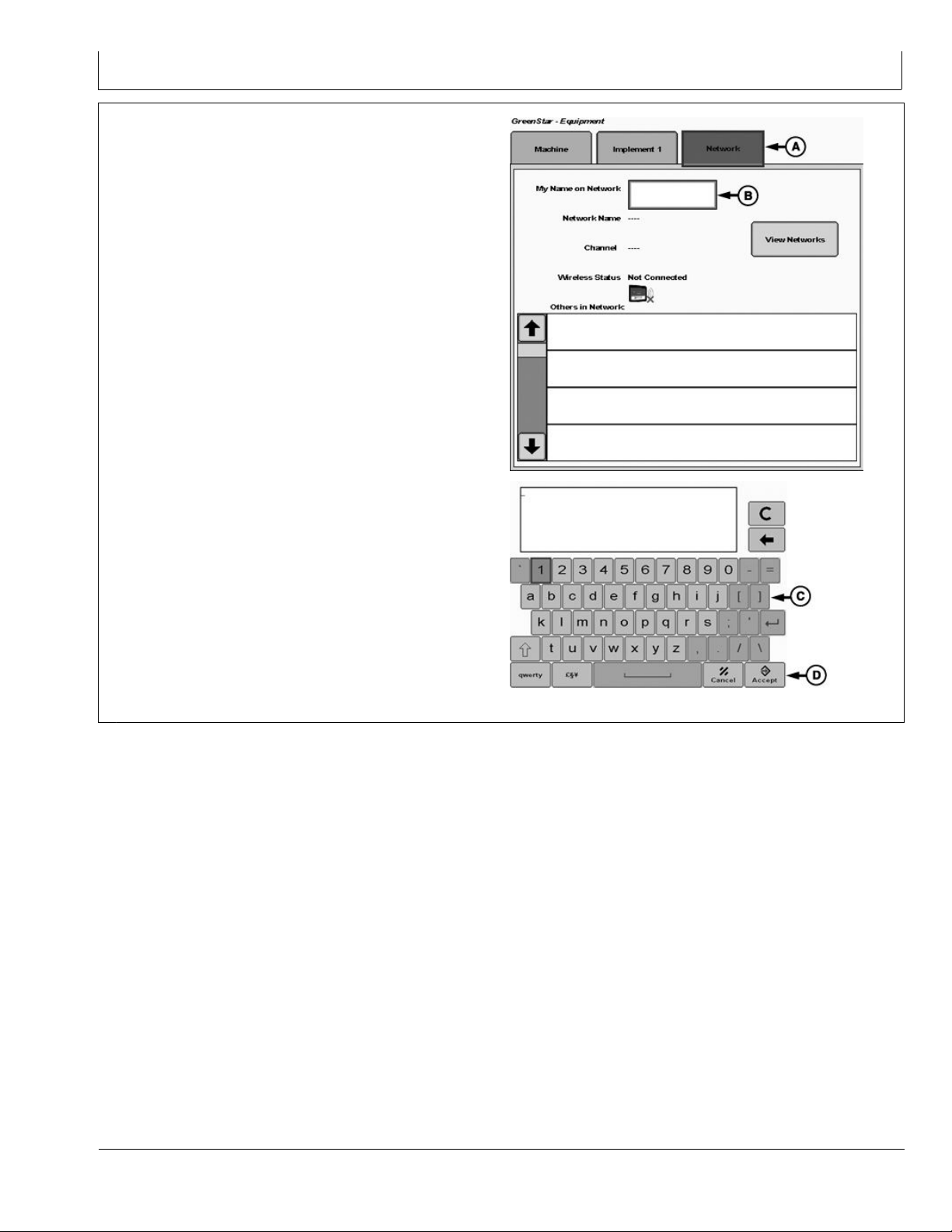
3. From Equipment screen, select Network tab.
4. Select My Name on Network box and use keyboard
to type a name to identify vehicle.
NOTE: My Name on Network can be 0-3 characters in
length and can contain upper case letters (A-Z),
lower case letters (a-z), and numbers (0-9).
5. Enter name and select Accept button.
A—Network Tab
B—My Name on Network
C—Keyboard
D—Accept Button
PC14301 —UN—06DEC11PC14302 —UN—07DEC11
CZ76372,00003A9 -19-12DEC11-2/2
20-8
052912
PN=17
Page 18
Conguring Radio
Verify Network Functionality
In order to communicate, all nodes in the network must:
connect to the same Network, having IDENTICAL
•
Network Name and Channel
be within communication range and have clear
•
line-of-sight between vehicles
have the same display software version
•
have the same radio rmware version
•
1. Once connected to a network, select Menu button and
select GS3 button.
2. Select Equipment softkey on the right side of main
menu.
PC8663 —UN—05AUG05
MENU button
PC12685 —UN—14JUL10
GREENSTAR 3 PRO button
PC8677 —UN—05AUG05
EQUIPMENT softkey
CZ76372,00003AA -19-12DEC11-1/3
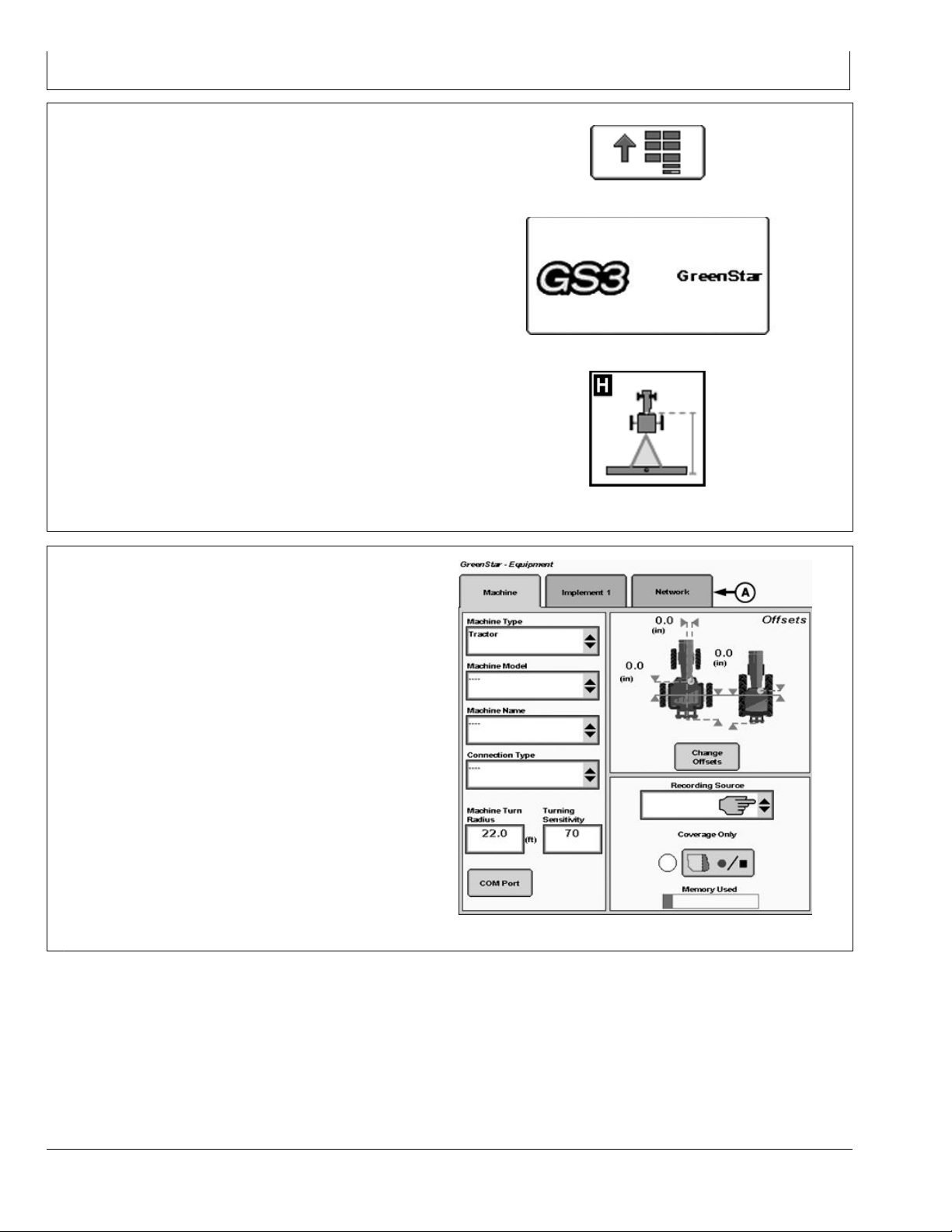
3. From Equipment screen, select Network tab (A).
A—Network Tab
PC14286 —UN—06DEC11
Continued on next page CZ76372,00003AA -19-12DEC11-2/3
20-9
052912
PN=18
Page 19

Conguring Radio
4. All other vehicles in network will be displayed in Others
in Network list (A).
The name shown in this list is the name entered for My
Name on Network (B) on other displays.
Other vehicles will appear in the list as they come into
range or join the network.
5. There will be 5 bars (C) next to each node in the list.
These will be lled in with color based on strength of
signal between your node and that vehicle.
A—My Name on Network
B—Status Bars
PC14303 —UN—12DEC11
CZ76372,00003AA -19-12DEC11-3/3
20-10
052912
PN=19
Page 20
Reprogram Radio
Update Radio Software
1. Plug radio into display with Ethernet cable and make
sure radio is powered.
2. Insert USB drive with new radio software in to GS3
display. Power up display.
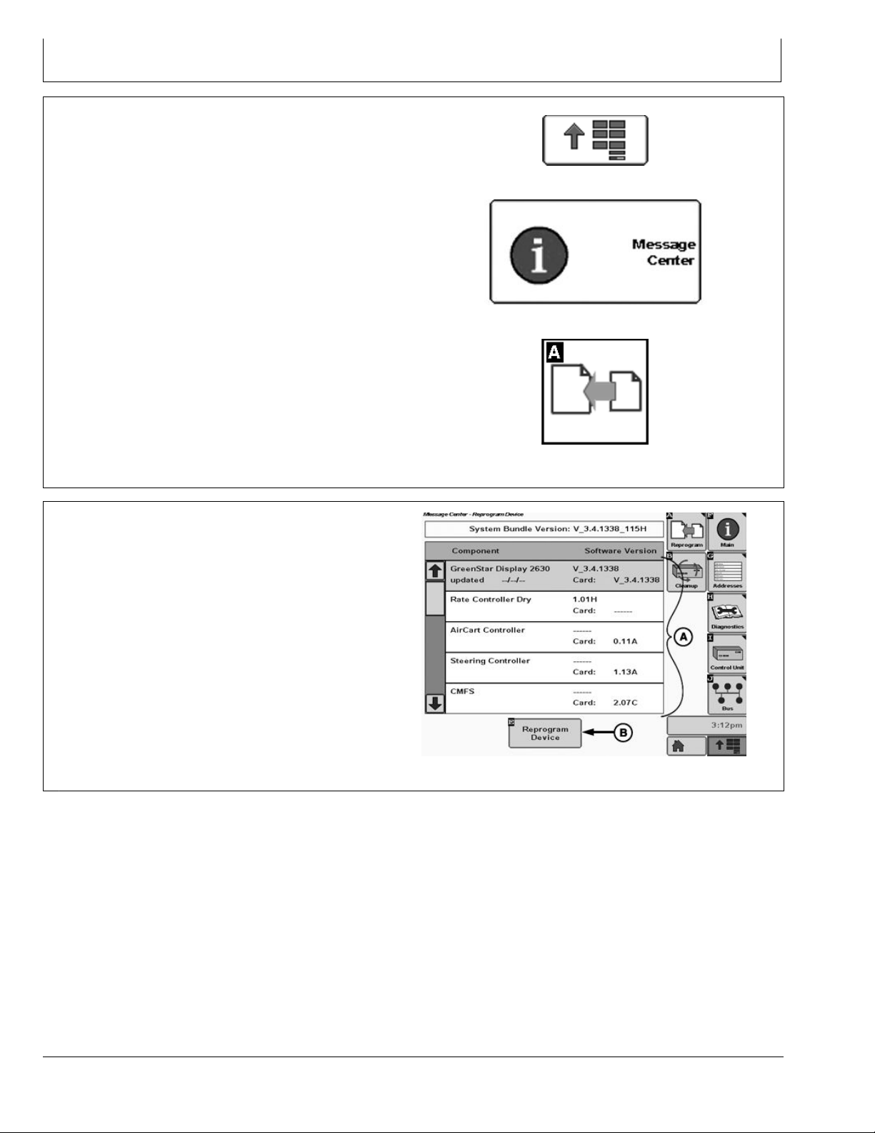
3. Select Main Menu button. Select Message Center.
Select Reprogram softkey.
A—Controller List
B—Reprogram Device
PC8663 —UN—05AUG05
MENU button
PC12868 —UN—16SEP10
MESSAGE CENTER button (With Info Icon)
PC8665 —UN—05AUG05
COMPONENTS AND SOFTWARE VERSIONS button
CZ76372,00003AB -19-12DEC11-1/3
4. Highlight MCR in controller list (A) and select
Reprogram Device (B).
A—Controller List
B—Reprogram Device Button
PC13666 —UN—07DEC11
Continued on next page CZ76372,00003AB -19-12DEC11-2/3
25-1
052912
PN=20
Page 21
Reprogram Radio
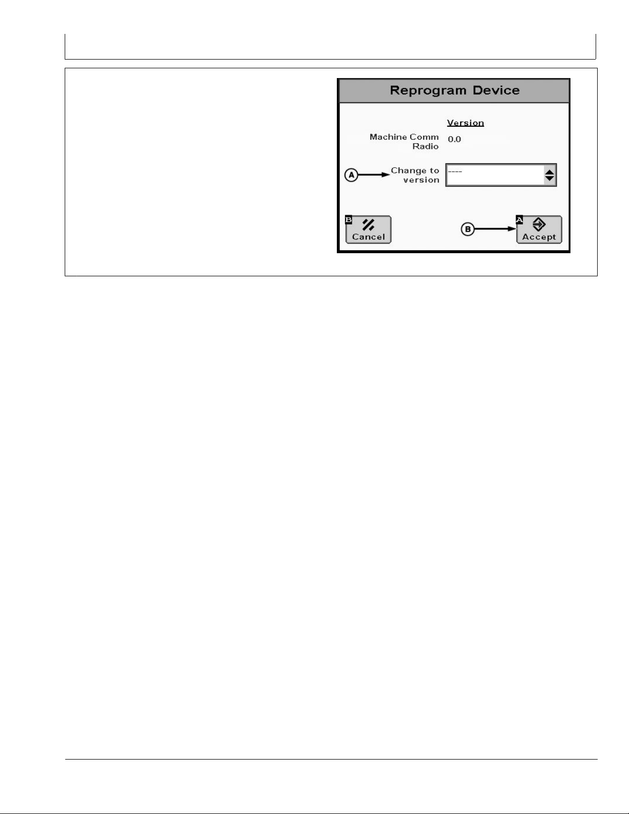
5. Select the new software version in Change To Version
(A) drop down box.
6. Select Accept (B) button to start update.
A—Change to Version
B—Accept Button
PC13667 —UN—07DEC11
CZ76372,00003AB -19-12DEC11-3/3
25-2
052912
PN=21
Page 22

Network Tab
Network Information
A—My Name on Network
B—Network Name
My Name on Network
The name shown on neighbors’ Others in Network list.
•
See Set My Name on Network for more information.
Network Name
The name of the currently connected network. Shows
•
“----“ if not connected. See Create Network for more
information.
Channel
The communication channel of the currently connected
•
network. Shows empty if not connected. See Radio
Specications for more information.
C—Channel
D—Wireless Status
Network Tab
E—View Networks
F— Others in Network list
Wireless Status
Shows Connected when local node is communicating
•
with at least one neighbor node. See Verify Network
Functionality and Radio Troubleshooting for more
information.
View Networks
Select to connect to or disconnect from networks. Use
•
to create, edit, delete networks. See Create Network
for more information.
Others in Network list
Each row in the list is one neighbor. Neighbor’s name
•
(My Name on Network entered on other display) appears
rst. Neighbor’s signal strength appears second
PC13678 —UN—12DEC11
CZ76372,00003B2 -19-12DEC11-1/1
30-1
052912
PN=22
Page 23

Network Diagnostics
Network Information
GS3 Network Diagnostics Page 1
A—My Name on Network
B—Ethernet Status
My Name on Network
The name shown on neighbors’ “Others in Network” list.
•
See Set My Name on Network for more details.
Ethernet Status
Shows “Connected” if 2630 is connected to MCR, MTG,
•
or other Ethernet enabled device.
Speed
Shows speed of the Ethernet connection on the 2630.
•
Speed should be “100” Mbps. If “10” is displayed,
there may be fault in the Ethernet cable(s), the 2630
hardware, or the MCR hardware.
Duplex
Normal operation will display “Full”. If “Half” is displayed,
•
there may be fault in the Ethernet cable(s), the 2630
hardware, or the MCR hardware.
C—Speed
D—Duplex
E—MAC Address
F— NAT Address
G—Network Application Version
MAC Address
Unique identier for 2630 on Network. All displays must
•
have unique MAC Address.
NAT Address
Unique identier for 2630 on Network. All displays must
•
have unique NAT Address.
Network Application Version
Version number for communication sub-assembly. All
•
displays and devices on Network must have same (or
compatible) version number.
Continued on next page CZ76372,00003B3 -19-12DEC11-1/3
PC13679 —UN—12DEC11
30-2
052912
PN=23
Page 24

Network Information
GS3 Network Diagnostics Page 3
A—NAT Address B—Uptime
C—Firmware Version
NAT Address
Unique identier for MCR on the network. All MCRs
•
must have a unique NAT address.
Uptime
Amount of time MCR has been running. The MCR
•
will reset each time the vehicle cycles keyed power.
If run time does not reasonably match time since
vehicle keying, there may be a wiring harness fault or
conguration failure.
Firmware Version
Software installed on MCR. All MCR’s in the network
•
must have the same rmware version. See Update
Radio Software for MCR reprogramming instructions.
Continued on next page CZ76372,00003B3 -19-12DEC11-2/3
PC13680 —UN—12DEC11
30-3
052912
PN=24
Page 25

Network Information
GS3 Network Diagnostics Page 4
A—Network Name
B—Channel
C—Connection Status
D—Packet Tx
Network Name
The name of the currently connected network. Shows
•
“----“ if not connected. See Create Network for more
information.
Channel
The communication channel of the currently connected
•
network. Shows empty if not connected. See Radio
Specications for more information.
Connection Status
Shows “Enabled” when connected to a network, even
•
if no neighbors are visible. Shows “Disabled” when
disconnected from a network.
E—Packet Rx
F— MAC Addres
Packet Tx
Number of messages transmitted from MCR.
•
Packet Rx
Number of messages received from other MCR’s.
•
MAC Address
Unique identier for MCR on Network. All MCR’s must
•
have unique MAC Address.
CZ76372,00003B3 -19-12DEC11-3/3
PC13681 —UN—12DEC11
30-4
052912
PN=25
Page 26

Troubleshooting
Radio Troubleshooting
Symptom Problem Solution
The radio does not show up on the
The radio does not have power
display
Conguration Check Connection Status on page
The radio does not show up on
Network set up incorrectly
OTHER displays
The radio exhibits decreased range Faulty antenna path
Low power availability Ensure Ethernet cable is securely
Interference from outside sources
Check the power/Ethernet cables,
ensure connections are tight. Radio
only operates on switched power.
LED will illuminate green when power
is properly connected.
1 of diagnostics. Status should be
Enabled when radio is powered and
joined to a network. Ensure display
software is updated.
All radios must have an IDENTICAL
Network Name and Channel in order
to communicate with each other.
Ensure that coax cable from the radio
to antenna is in good shape, and that
antenna is securely fastened. Ensure
antenna is not broken.
attached to the radio. Make sure the
radio LED is green.
There may be an outside system
interfering with the signal. Try
switching to a different Channel (all
nodes in network must switch in order
to keep communicating).
Signal Strength shows zero bars
Obstruction in path between vehicles The MCR is a line-of-sight system.
Any obstructions (trees, hills, parts
of the vehicle, etc) obstructing the
antennas from having a direct line of
sight will decrease the range of the
system.
Indirect nodes
The MCR is a line-of-sight system.
The MCR also utilizes advanced
networking features to communicate
with nodes that it cannot directly see,
but can see through other MCR nodes
in the network. In this case Zero Bars
of Signal does not mean there is a
problem.
Faulty antenna path
Check antenna to ensure a solid
connection.
Continued on next page CZ76372,00003AC -19-12DEC11-1/2
35-1
052912
PN=26
Page 27

Troubleshooting
Symptom Problem Solution
User cannot disassociate from a
Loss of communication with display Check Ethernet cable to ensure solid
network
MCR LED is blinking
Radio is not connected to a network. Led will blink until the radio is
Cap Antenna Connections
Contamination in antenna connections can contribute
to poor radio performance. Ensure antenna connectors
on radio and on roof are covered when antenna is not
connections.
connected to a network. If the radio
loses connection to a network, the
LED will stay solid until power is
cycled on the radio.
CZ76372,00003AC -19-12DEC11-2/2
connected. If you anticipate having to remove the antenna
for transport or storage, John Deere recommends using
the cap which came on the radio antenna connector to
keep this in good working order.
CZ76372,00003AD -19-12DEC11-1/1
35-2
052912
PN=27
Page 28

Specications
Radio Specications
Frequency: 2.4 GHz
Range of Operation: 3 mile radius (line-of-sight)
Channel ID
Channel #
Center frequencies (MHz)
EC Declaration of Conformity
The undersigned hereby declares that:
Product: John Deere Machine Communication Radio
Part Number: PFA10196
Fullls all relevant provisions and essential requirements of the following directives:
A B
1
2412 2432 2452
Deere & Company
Moline, Illinois U.S.A.
C
5
9
CZ76372,00003AE -19-12DEC11-1/1
Directive Number
Radio and Telecommunications Terminal
Equipment Directive (R&TTE)
The product is in conformity with the following standards and/or other normative documents:
Name and address of the person in the European Community authorized to compile the technical construction le:
Place of declaration: Kaiserslautern, Germany Name: Aaron Senneff
Date of declaration: 9 December 2011
DXCE01 —UN—28APR09
1999/5/EC
ETSI EN 300 328-2 V1.7.1
ETSI EN 301 489-17 V2.1.1
ETSI EN 301 489-1 V1.8.1
ETSI EN60950-1 Second Ed.
Brigitte Birk
Deere & Company European Ofce
John Deere Strasse 70
Mannheim, Germany D-68163
EUConformity@JohnDeere.com
Title: Engineering Manager, John Deere Intelligent
Solutions Group
Manufacturing Unit: John Deere Intelligent Solutions Group
Annex III
Certication Method
CZ76372,00003AF -19-14DEC11-1/1
40-1
052912
PN=28
Page 29

Index
Page
C
Components ............................................................... 15-1
Congure Radio
Create Network ....................................................... 20-1
Set My Name on Network ....................................... 20-7
Verify Network Functionality.................................... 20-9
Create Network........................................................... 20-1
M
Machine Communication Radio
Components............................................................ 15-1
Congure Radio ...................................................... 20-1
Reprogram Radio.................................................... 25-1
Specications.......................................................... 40-1
Theory of Operation................................................ 15-1
Troubleshooting ...................................................... 35-1
R
Radio Specications ................................................... 40-1
Regulatory Notication ............................................... 10-1
Canada ................................................................... 10-1
European Community ............................................. 10-1
United States .......................................................... 10-1
Reprogram Radio
Update Radio Software........................................... 25-1
S
Set My Name on Network........................................... 20-7
T
Theory of Operation.................................................... 15-1
Troubleshooting
Antenna Connections.............................................. 35-2
Machine Communication Radio.............................. 35-1
U
Update Radio Software .............................................. 25-1
V
Verify Network Functionality ....................................... 20-9
Index-1
052912
PN=1
Page 30

Index
Index-2
052912
PN=2
Page 31
John Deere Service Literature Available
Technical Information
Technical information can be purchased from John Deere.
Some of this information is available in electronic media,
such as CD-ROM disks, and in printed form. There are
many ways to order. Contact your John Deere dealer.
Call 1-800-522-7448 to order using a credit card. Search
online from http://www.JohnDeere.com. Please have
available the model number, serial number, and name of
the product.
Available information includes:
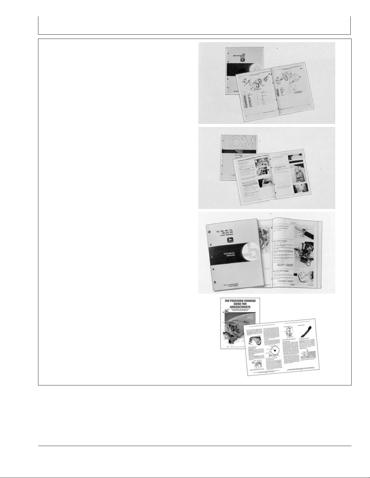
PARTS CATALOGS list service parts available for your
•
machine with exploded view illustrations to help you
identify the correct parts. It is also useful in assembling
and disassembling.
OPERATOR’S MANUALS providing safety, operating,
•
maintenance, and service information. These manuals
and safety signs on your machine may also be available
in other languages.
OPERATOR’S VIDEO TAPES showing highlights of
•
safety, operating, maintenance, and service information.
These tapes may be available in multiple languages
and formats.
TECHNICAL MANUALS outlining service information
•
for your machine. Included are specications, illustrated
assembly and disassembly procedures, hydraulic oil
ow diagrams, and wiring diagrams. Some products
have separate manuals for repair and diagnostic
information. Some components, such as engines, are
available in separate component technical manuals
FUNDAMENTAL MANUALS detailing basic information
•
regardless of manufacturer:
- Agricultural Primer series covers technology in farming
and ranching, featuring subjects like computers, the
Internet, and precision farming.
- Farm Business Management series examines
“real-world” problems and offers practical solutions
in the areas of marketing, nancing, equipment
selection, and compliance.
- Fundamentals of Services manuals show you how to
repair and maintain off-road equipment.
- Fundamentals of Machine Operation manuals
explain machine capacities and adjustments, how to
improve machine performance, and how to eliminate
unnecessary eld operations.
TS189 —UN—17JAN89TS191 —UN—02DEC88TS224 —UN—17JAN89TS1663 —UN—10OCT97
SLIT-1
DX,SERVLIT -19-31JUL03-1/1
052912
PN=31
Page 32

John Deere Service Literature Available
SLIT-2
052912
PN=32
Page 33

John Deere Service Keeps You On The Job
John Deere Is At Your Service
CUSTOMER SATISFACTION is important to John Deere.
Our dealers strive to provide you with prompt, efcient
parts and service:
–Maintenance and service parts to support your
equipment.
–Trained service technicians and the necessary diagnostic
and repair tools to service your equipment.
CUSTOMER SATISFACTION PROBLEM RESOLUTION
PROCESS
TS201 —UN—23AUG88
2. Discuss problem with dealer service manager.
Your John Deere dealer is dedicated to supporting your
equipment and resolving any problem you may experience.
1. When contacting your dealer, be prepared with the
following information:
–Machine model and product identication number
–Date of purchase
–Nature of problem
3. If unable to resolve, explain problem to dealership
manager and request assistance.
4. If you have a persistent problem your dealership is
unable to resolve, ask your dealer to contact John Deere
for assistance. Or contact the Ag Customer Assistance
Center at 1-866-99DEERE (866-993-3373) or e-mail us at
www.deere.com/en_US/ag/contactus/.
DX,IBC,2 -19-02APR02-1/1
IBC-1
052912
PN=33
Page 34

John Deere Service Keeps You On The Job
IBC-2
052912
PN=34
Page 35

John Deere Service Keeps You On The Job
IBC-3
052912
PN=35
Page 36

John Deere Service Keeps You On The Job
IBC-4
052912
PN=36
 Loading...