

Page 1

I0
Snow Blade
46 Inch
OMGX10902 I0
OPERATOR’S MANUAL
North American Version
Litho in U.S.A.
Page 2

INTRODUCTION
Introduction
Thank You for Purchasing This Product
We appreciate having you as a customer and wish you
many years of safe and satisfied use of your machine.
Using Your Operator’s Manual
This manual is an important part of your machine and
should remain with the machine when you sell it.
Reading your operator’s manual will help you and others
avoid personal injury or damage to the machine.
Information given in this manual will provide the operator
with the safest and most effective use of the machine.
Knowing how to operate this machine safely and correctly
will allow you to train others who may operate this machine.
This manual and safety signs on your machine may also be
available in other languages (see your John Deere dealer
to order).
Sections in your operator’s manual are placed in a specific
order to help you understand all the safety messages and
learn the controls so you can operate this machine safely.
You can also use this manual to answer any specific
operating or servicing questions. A convenient index
located at the end of this book will help you to find needed
information quickly.
IMPORTANT: Avoid damage! This text is used to tell
the operator of actions or conditions that might
result in damage to the machine.
NOTE: General information is given throughout the
manual that may help the operator in the operation or
service of the machine.
The machine shown in this manual may differ slightly from
your machine, but will be similar enough to help you
understand our instructions.
RIGHT-HAND and LEFT-HAND sides are determined by
facing in the direction the machine will travel when going
forward. When you see a broken line arrow (------>), the
item referred to is hidden from view.
Before delivering this machine, your dealer performed a
predelivery inspection to ensure best performance.
Special Messages
Your manual contains special messages to bring attention
to potential safety concerns, machine damage as well as
helpful operating and servicing information. Please read all
the information carefully to avoid injury and machine
damage.
c
CAUTION: Avoid injury! This symbol and text
highlight potential hazards or death to the
operator or bystanders that may occur if the
hazards or procedures are ignored.
Introduction
Page 3
PRODUCT IDENTIFICATION
Product Identification
Record Identification Numbers
Snow Blade for Lawn Tractors
46 Inch
Serial No. (010001 - )
If you need to contact an Authorized Service Center for
information on servicing, always provide the product model
and serial number.
You will need to locate the identification number for the
machine and for the engine. Record the information in the
spaces provided below.
A
M92898C
DATE OF PURCHASE:
_________________________________________
DEALER NAME:
_________________________________________
DEALER PHONE:
_________________________________________
SERIAL NUMBER (A):
__ __ __ __ __ __ __ __ __ __ __ __ __ __ __ __ __
Product Identification
Page 4

TABLE OF CONTENTS
Table of Contents
Safety .....................................................................................................................................................................................1
Preparing Vehicle ...................................................................................................................................................................3
Installing .................................................................................................................................................................................4
Removing ...............................................................................................................................................................................6
Operating................................................................................................................................................................................7
Troubleshooting ....................................................................................................................................................................10
Storage .................................................................................................................................................................................11
Assembly ..............................................................................................................................................................................12
Specifications .......................................................................................................................................................................18
Index.....................................................................................................................................................................................19
All information, illustrations and
specifications in this manual are based
on the latest information at the time of
publication. The right is reserved to
make changes at any time without
notice.
COPYRIGHT© 2000
Deere & Co.
John Deere Worldwide Commercial and
Consumer Equipment Division
Horicon, WI
All rights reserved
Previous Editions
COPYRIGHT© 1999
Table of Contents
OMGX10902 I0 - English
Page 5
Safety
Understanding The Safety-Alert Symbol
SAFETY
• DO NOT leave machine unattended when it is running.
The operator’s manual explains any potential safety
hazards whenever necessary in special safety messages
that are identified with the word, CAUTION, and the safetyalert symbol, (
c
).
Operate Safely
• Check vehicle brake action before you operate. Adjust
or service brakes as necessary.
• Inspect machine before you operate. Be sure hardware
is tight. Repair or replace damaged, badly worn, or missing
parts. Be sure guards and shields are in good condition
and fastened in place. Make any necessary adjustments
before you operate.
• Clear work area of objects that might be thrown. Keep
people and pets out of the work area. Stop machine if
anyone enters the area.
• DO NOT operate machine at high speeds.
• DO NOT use blade as a battering ram.
• Look carefully behind machine before you back up.
• DO NOT let anyone, ESPECIALLY CHILDREN, ride on
machine or vehicle.
• DO NOT let children or untrained person operate
machine.
• Only operate during daylight or with good artificial light.
• Be careful of traffic when operating near or crossing
roadways.
• Do not wear radio or music headphones while operating
the machine. Safe operation requires your full attention.
• DO NOT operate equipment when you are tired, ill, or
under the influence of drugs or alcohol.
• If you hit an object, stop the machine and inspect it.
Make repairs before you continue to operate. Keep
machine and attachments properly maintained and in good
working order.
• Raise blade when you are driving between jobs or when
you are not moving snow.
Safety - 1
Page 6

SAFETY
Wear Appropriate Clothing
• Wear close fitting clothing and safety equipment
appropriate for the job.
• Loud noise can cause impairment or loss of hearing,
wear a suitable protective device such as earplugs.
Park Safely
• Stop machine on a level surface, not on a slope.
• Disengage Power Take-Off (PTO).
• Lower attachments to the ground.
• Lock the park brake.
• Stop the engine.
• Remove the key.
• Wait for engine and all moving parts to stop before you
leave the operator’s seat.
• Close fuel shut-off valve, if your machine is equipped.
Safety - 2
Page 7

PREPARING VEHICLE
Preparing Vehicle
Remove Mower Deck
The mower deck must be removed from before installing
the snow blade. See your machine operator’s manual or
mower deck manual for removal instructions.
Ballasting Requirements
Follow these recommendations to help improve traction:
• Install tire chains on turf tires or install bar tires on the
machine.
• Install rear wheel weights.
Ballast weights can be purchased from your Authorized
Service Center. See your machine operator’s manual for
further information.
Check Tire Pressure
See your machine’s operator’s manual for proper tire
pressures.
Preparing Vehicle - 3
Page 8
Installing
Install Lift Arms
INSTALLING
NOTE: Align the machine directly behind the blade
assembly before parking the machine.
1. Park the machine safely. (See Parking Safely in the
Safety section.)
A
D
B
E
C
2. Install one 1/2 x 1-1/2 x 3/16 in. flat washer (A) onto the
pin of each lift arm (B).
3. Insert the blank end of the lift arms behind the guide
rods (C) of the machine lift at each side of machine.
NOTE: The lift handle must be in its lowest position.
D
C
E
3. Raise rear of blade frame and slide onto drawbar (C) of
machine.
4. Fasten with hitch pin (D) and large spring locking pin
(E).
I
F
4. Insert the pins of the lift arms into the holes in the frame
rail (D) of the machine and secure with spring locking pins
(E).
Install Blade
A
B
M92905
1. Unlock park brake, put gear transmission in neutral or
pull out free-wheeling lever and push machine forward until
rear mounting bracket (A) of blade assembly is behind
drawbar (B) of machine.
H
G
5. Insert long end of each front stabilizer pin (F) into tube
of front stabilizer bracket (G).
6. Insert short end of each front stabilizer pin into front
mower mounting holes located on underside of front axle,
place spacer (I) over end of pin and secure with spring
locking pins (H).
Install Lift Links to Blade Frame and Lift Arms
c
CAUTION: Avoid injury! Lift lever is under
tension. Grasp lift lever securely and release
lock mechanism slowly.
1. Put lift lever one notch up from its lowest position.
2. Lock park brake.
Installing - 4
Page 9

INSTALLING
Install Pivot Handle Support
B
C
A
D
2. Insert threaded end of lift links down through holes in lift
channel (A) and bent end of lift links through holes in lift
arms (B).
3. Fasten bent ends of lift links (C) to lift arms with spring
locking pin.
4. Thread 3/8 in. nylock nut and 5/16 in. flat washer (D),
one on each side until they seat against lift channel (C).
Install Pivot Control Handle
F
A
B
A
E
C
M92907
1. Slide eye of pivot handle support (A) onto pivot control
handle (B).
E
C
D
A
M85797
C
D
B
E
M92906
1. Insert handle end of pivot control handle (A) through eye
bolt (B) and slide it all the way to bracket end of pivot
control handle.
2. Hook pivot release rod (C) into hole of bracket at end of
pivot control handle and fasten with spring clip (D).
3. Lay pivot control handle along side of machine onto
wheel and footrest of machine. Make sure hook of bracket
on end of pivot control handle is to the right of the eye bolt.
4. Slide 3/8 x 1 in. flat washer onto handle end of pivot
control handle and slide all the way to eye bolt.
5. Install spring locking pin (E) through pivot control handle
to hold washer against eye bolt.
6. Install rubber handle grip (F) to handle of pivot control
handle.
2. Insert pivot handle support through 1/2 in. hole in thrust
channel (C) and place strap over nut (D) of thrust channel.
Secure with spring locking pin (E) on opposite side of thrust
channel.
Installing - 5
Page 10

Removing
Remove Blade
REMOVING
c
CAUTION: Avoid injury! Before removing frame
assembly: Make sure hands and arms are not
under frame assembly.
1. Park machine safely. (See Parking Safely in the Safety
section.)
2. Put blocks of wood or a board under blade.
3. Push machine lift lever down lowering blade onto blocks
or board and lock lever in lowest position.
E
G
D
A
B
C
F
4. Remove spring locking pins (A) and remove lift links (B)
from lift straps (C). Install locking pins back to lift links.
J
I
M92907
7. Remove spring locking pin (I) from pivot control handle
support (J) and install spring locking pin back to handle
support.
8. Remove rubber handle grip and slide pivot control
handle support off of pivot control handle.
L
M
K
5. Remove spring locking pins (D) and washers (E).
Remove lift straps (C) from behind guide rods (F) and
frame rails (G). Install spring locking pins and washers
back to lift links.
F
H
G
6. Remove spring locking pins (H), spacers, and front
stabilizer pins (F) from tube of front stabilizer bracket (G).
Install spring locking pins back into stabilizer pins.
M92906
9. Remove spring locking pin (K) and spring clip (L) and
unhook pivot release rod (M) from pivot control handle.
Install spring clip and spring locking pin.
10.Remove pivot control handle and install rubber handle
grip to handle.
O
P
N
11.Remove spring locking pin (N) and clevis pin (O) from
drawbar (P). Lower frame assembly to the ground.
12.Remove blade assembly from under machine.
Removing - 6
Page 11

Operating
Before Operating Blade
1. Learn all controls and how they work. Read your
machine's operator manual, if necessary.
2. Lock park brake.
3. Stop engine.
4. Remove key.
OPERATING
B
5. Make operating adjustments as necessary.
6. Tighten loose hardware.
Rotating Scraper Blade
1. Park machine safely. (See Parking Safely in the Safety
section.)
2. Raise blade and place wood block under frame channel.
B
A
M92908
A
3. Tighten both 3/8 nylock nuts (A) up to the bottom of the
lift channel (B).
Leveling Blade from Side to Side
1. Park machine on a level surface.
2. Place mower lift handle in the TRANSPORT (upper)
position.
A
3. Remove six 5/16 carriage bolts and six 5/16 nylock nuts
(A) to remove scraper blade (B).
4. Turn scraper blade over and install scraper blade.
5. Adjust skid shoes.
Adjusting Lift Height
1. Park machine safely. (See Parking Safely in the Safety
section.)
2. Place the mower lift lever one notch up from its lowest
position.
Operating - 7
Picture Note: Level side to side (A).
3. Measure at each end of blade.
NOTE: Do not adjust nut of lift link up more than two
turns without lowering opposite side lift link.
B
4. If one side of blade is low, adjust nut (B) on lift link UP
on that side to level blade.
Page 12

OPERATING
Adjusting Skid Shoes
When clearing snow on smooth surfaces, skid shoes
should be approximately 1/4 inch above ground level.
When clearing snow on uneven surfaces, skid shoes
should keep blade above ground level. Height above
ground level should be based on the unevenness of your
surface.
1. Park machine on a level surface.
2. Raise lift lever to the TRANSPORT (upper) position.
3. Place a block of wood beneath each end of the blade.
4. Lower blade onto blocks of wood.
A
For transport, pull lift lever back to the highest position.
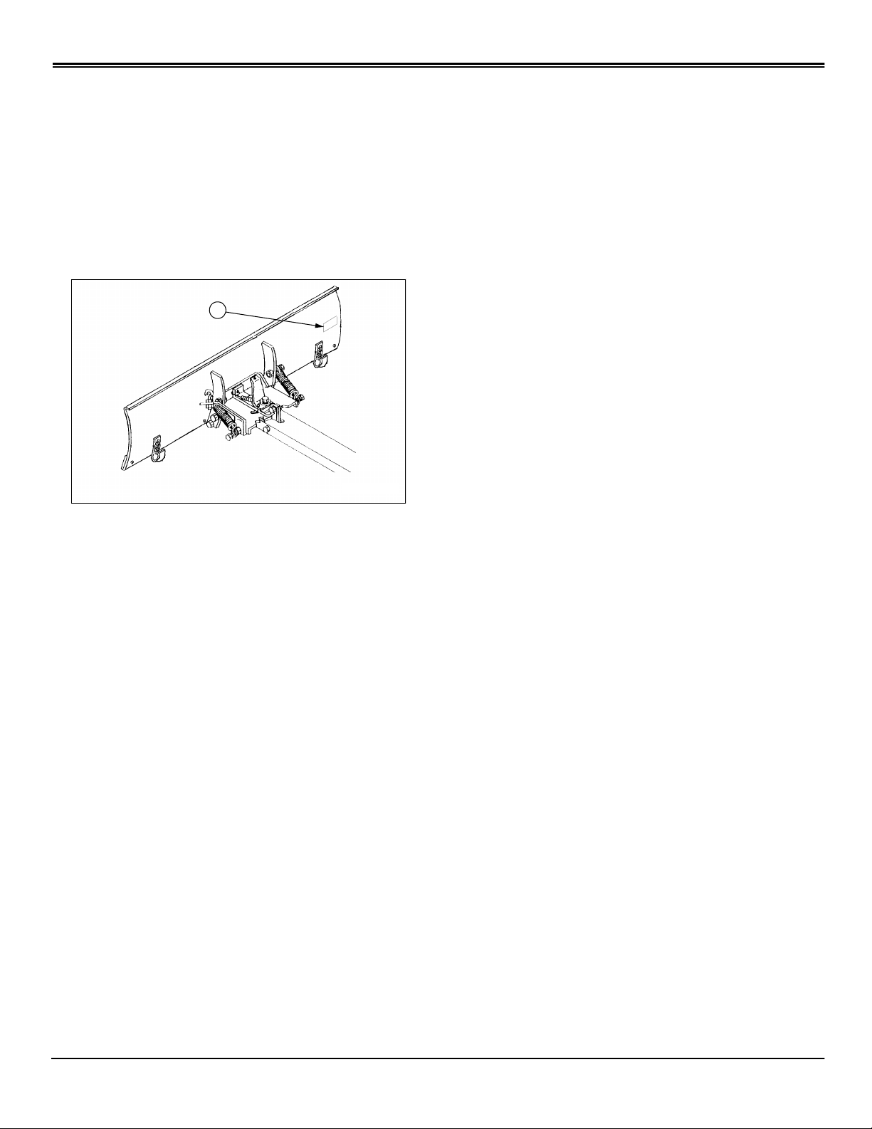
Adjusting Blade Angle
A
MX6533A
Picture Note: Reference Blade Angling Label (A)
located on the back side of the blade in the upper
left corner.
MX6534
5. Loosen nuts (A) and adjust skid shoes as necessary.
Tighten nuts.
Using Lift Lever to Raise and Lower Blade
A
B
1. Push down on lift lever (A) slightly and hold locking lever
(B) down with thumb.
2. Move lift lever (A) DOWN to LOWER blade or UP to
RAISE blade.
3. Release locking lever lock (B) to keep lift lever (A) in
position.
For scraping/snow removal, push lift lever down to the
lowest position.
B
M92909
1. Place blade in the raised position.
2. Turn release latch (B) counterclockwise and hold.
3. Push forward on pivot control handle to angle blade to
the right, or pull back on pivot control handle to angle blade
to the left.
4. Release pivot control handle to lock in position.
5. Lower blade to the operating position.
Operating Tips
c
CAUTION: Avoid injury! DO NOT use blade as a
battering ram. Do Not operate at a high speed.
Hitting a solid object at high speeds can injure
the operator and damage the blade.
Operate blade at slow travel speed.
This blade is designed to move new loose snow in depths
Operating - 8
Page 13

OPERATING
up to 6 inches. Blade is not intended to move gravel or dirt.
Operate engine at full throttle for best performance, control
ground speed using lower gears or foot controls.
Put Blade On An Angle:
• When clearing material to the side.
• To decrease amount of power required to move
material.
• To decrease rear wheel slippage.
Use Blade In Straight-across Position:
• To move material straight ahead.
After You Are Finished Using Blade:
• Park machine on hard, level surface.
• Stop engine.
• Lock park brake.
• Remove key.
• Put blocks of wood or a board under blade.
• Lower blade onto blocks of wood by pushing lift lever
forward until it locks down in lowest position.
Operating - 9
Page 14

TROUBLESHOOTING
Troubleshooting
Using Troubleshooting Chart
If you are experiencing a problem that is not listed in this
chart, see your Authorized Service Center for service.
When you have checked all the possible causes listed and
you are still experiencing the problem, see your Authorized
Service Center.
IF CHECK
Engine Lugs Down Run engine at full throttle.
Blade angle.
Raise blade to float position.
Adjust skid shoes.
Blade Digs In Too Deep Raise blade to float position.
Adjust skid shoes.
Rear Wheels Slip Add rear weights and chains.
Troubleshooting - 10
Page 15

STORAGE
Storage
Storing Blade
Clean the blade with water under pressure.
If possible, store blade indoors on hard, level surface.
If you store blade outside:
• Put blocks of wood or a board under blade.
• Cover blade with a waterproof cover.
Inspect blade. Repair or replace badly worn or damaged
parts. Check all bolts, nuts, and pins to make sure they are
secure.
Apply touch-up paint where needed to prevent rust.
Oil all pivot points so that they will work freely.
Grease blade pivot plate, thrust channel, pivot plate
reinforcement and pivot release bracket.
Storage - 11
Page 16

Assembly
Box of Parts
ASSEMBLY
Key Description
C
A
D
A Blade Assembly
B Pivot Plate
C Rear Mounting Bracket
D Lift Channel
E Pivot Control Handle
E
F Pivot Handle Support
G
F
G (2) Rear Support Channel
H Thrust Channel
B
I Blade Pivot Bracket
J Front Stabilizer Bracket
K Pivot Release Rod
H
L(2) Strap
J
I
M
M (2) Front Stabilizer Pin
N (2) Spacer
O (2) Lift Link
P Pivot Plate Reinforcement
N
K
L
P
O
Q Pivot Control Rod
R Pivot Release Bracket
S Rear Locating Bracket
T (2) Lift Arm
Q
U Drawbar Support Plate
Operator’s Manual
S
Bag of Parts
R
Bag of Parts
T
M92899
Qty Description Size
2 Return Spring
U
1 Full Thread Bolt 3/8 x 4-1/2 in.
1 Rubber Handle Grip
1 Idler Spring
1 Spacer 3/8 x 1/2 x 1/4 in.
Assembly - 12
Page 17

ASSEMBLY
Qty Description Size
2 Flat Washer 5/16 Flat
3 Cotter Pin .094 x.75
1 Flat Washer 1/2 x 2 in.
2 Flat Washer 3/8 x 1-1/2 in.
4 Hex Head Bolt 5/16 x 1-1/4 in.
2 Hex Head Bolt 5/16 x 5/8 in.
4 Hex Head Bolt 5/16 x 2-1/2 in.
3 Flat Washer 3/8 x 1 in.
3 Lock Washer 3/8 in.
1 Nylock Nut 5/8 in.
1 Eye Bolt 3/8 x 2 in.
6 Hex Lock Nut 5/16 in.
1 Hex Head Bolt 5/8 x 1-3/4 in.
2 Hex Head Bolt 1/2 x 1in.
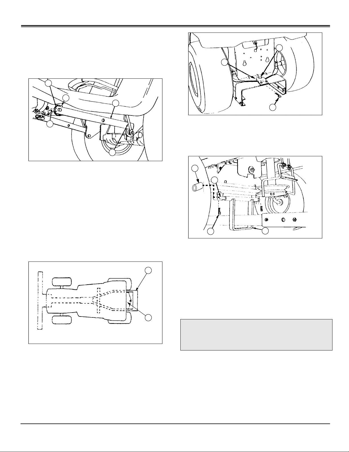
Install Drawbar Support Plate
B
A
1. Place drawbar support plate (A) under rear axle and
under drawbar (B).
2. Align drawbar holes with axle holes.
3. Install four 5/16 x 2-1/2 in. hex head bolts (C) and four 5/
16 in. lock nuts (D).
C
D
Install Parts to Blade Assembly
8 Spring Locking Pin .095 DIA x 1-5/8 in.
1 Spring Locking Pin 0.148 DIA x 2-7/8 in.
1 Flat Washer 21/32 x 1-5/16 in.
1 Hitch Pin 5/8 x 1-7/8 in.
2 Spring Clip .065 DIA x.72 in. OD
1 Full Thread Bolt 3/8 x 2-1/2 in.
2 Hex Lock Nut 1/2 in.
2 Flat Washer 1/2 x 1-1/2 x 3/16 in.
8 Nut/Lock Washer Assembly 5/16 in.
13 Hex Head Bolt 3/8 x 1 in.
18 Nylock Nut 3/8 in.
3 Hex Nut 3/8 in.
Grease
Use a SAE Multi-purpose grease based on the expected air
temperature range during the service interval.
C
B
A
E
D
M93033B
1. Assemble spring anchor bolts:
a. Turn one 5/16 in. nut and lock washer assembly (B)
onto the 5/16 x 1-1/4 in. hex head bolt (A) with lock
washer away from the head of the bolt.
b. Insert the bolt and nut assembly (A & B) through hole
in rib of blade assembly then assemble with a second 5/
16 in. nut and lock washer assembly (C) onto bolt (A).
c. Adjust inside nut and lock washer (B) flush with end
of thread on bolt then tighten nut and lock washer (C)
against blade rib.
d. Assemble second 5/16 x 1-1/4 in. bolt to opposite
side of blade assembly using the same procedure.
Assembly - 13
Page 18

ASSEMBLY
2. Assemble breakover stop bolt:
• Install one 5/16 x 5/8 in. hex bolt (D) into bottom hole
of each rib on blade assembly and fasten with 5/16 in.
lock nut (E).
Assemble Pivot Plate to Thrust Channel
D
B
A
C
E
F
M93035
1. Assemble the pivot plate (A) and the pivot plate
reinforcement (B) on top of the thrust channel (C).
2. Lubricate thrust channel, pivot plate, and pivot plate
reinforcement in areas of contact with light multi-purpose
grease.
3. Insert 5/8 x 1-3/4 in. hex head bolt (D) through the pivot
plate reinforcement, pivot plate, and the thrust channel and
fasten with 21/32 x 1-5/16 in. flat washer (E) and 5/8 in.
nylock nut (F).
4. Loosen 5/8 in. nylock nut approximately 1/4 turn to allow
the assembly to pivot freely.
Assemble Pivot Release Bracket, Pivot Plate, and Thrust Channel
G
C
B
D
J
1. Lubricate large hole and two faces of pivot release
bracket (A) with light multi-purpose grease.
2. Assemble idler spring (B) into smallest hole of pivot
release bracket (A).
3. Place 3/8 in. lock washer (C), 3/8 x 1-1/2 in. flat washer
(D), pivot release bracket (A), large 1/2 x 2 in. flat washer
(F), and spacer (E) onto 3/8 x 2-1/2 in. full thread bolt (G).
NOTE: Make sure pivot release bracket and large
1/2 x 2 in. flat washer (F) pivot freely after bolt is tight.
4. Align holes in thrust channel (H) with pivot plate
reinforcement (I) and thread 3/8 x 2-1/2 in. full thread bolt
(G) with parts assembled into hole and tighten securely.
D
A
F
E
I
H
M93036
NOTE: Tightening of nut (J) will cause loosening of 3/8
x 2-1/2 bolt (G) unless bolt is held with a back-up
wrench.
5. Place 3/8 x 1-1/2 in. flat washer (D) onto bottom of
3/8 x 2-1/2 in. full thread bolt and fasten with 3/8 in. nylock
nut (J). Loosen nut approximately 1/4 turn until pivot plate
pivots freely.
6. Hook other end of idler spring (B) to pivot plate
reinforcement.
Assembly - 14
Page 19

ASSEMBLY
Assemble Pivot Latch Strap
G
F
E
G
B
C
A
1. Insert 3/8 x 4-1/2 in. full thread bolt (A) through one side
of thrust channel (B), approximately half way.
C
D
M93038
Install Pivot Control Rod
NOTE: Pivot control rod (A) must be rotated from
pictured orientation in order to access grooved side of
spring locking pin hole.
D
C
A
C
1. Assemble pivot control rod (A) into pivot latch straps (B)
and fasten with two cotter pins (C) by inserting each
through the grooved side of the pivot control rod on each
side of pivot latch straps.
2. Assemble other end of pivot control rod (A) into hole of
pivot release bracket (D) and fasten with cotter pin (C).
B
M93037
2. Assemble one 3/8 in. hex nut (D) (non-locking) and 3/8
in. lock washer (C) onto hex bolt (A) approximately 1 inch
from head of bolt.
3. Place two pivot latch straps (E) together and fasten with
3/8 x 1 in. hex bolt (F) and 3/8 in. nylock nut (G). Insert
pivot latch straps through slot of the thrust channel and
onto the hex bolt (A).
NOTE: Bolt (A) must pivot freely after 3/8 in. nylock nut
(G) is assembled.
4. Assemble second 3/8 in. hex nut (D) and 3/8 in. lock
washer (C) onto 3/8 x 4-1/2 in. full thread bolt and hand
tighten against pivot latch straps. Adjust two 3/8 in. hex
nuts to allow hex bolt (A) to pass through other side of
thrust channel and fasten bolt with 3/8 in. nylock nut (G).
5. Fasten pivot latch straps (E) in the center of slot of the
thrust channel with 3/8 in. hex nuts (D).
Assemble Blade Pivot Bracket and Eye Bolt
B
D
G
F
H
A
B
E
C
A
E
1. Turn one 5/16 in. nut and lock washer assembly (A)
onto one 5/16 x 1-1/4 in. hex bolt (B) with lock washers
Assembly - 15
M93039
Page 20

ASSEMBLY
away from the head of the bolt. Assemble two nuts and
bolts in this manner.
2. Place blade pivot bracket (C) on the left side of the pivot
plate (D). Insert bolt and nut assembly (A and B) and fasten
with another nut and lock washer assembly (E).
3. Install nut flush with end of bolt (B) and fasten to plate
with outside nut.
4. Install second bolt and nut assembly (A and B) into right
side of pivot plate and fasten with another nut and lock
washer assembly (E).
5. Assemble 3/8 in. hex nut (F) onto 2 in. eye bolt (G) and
turn it onto the eye end of the threads. Place wrench
through eyebolt to hold while tightening.
6. Assemble eyebolt to the blade pivot bracket (C) and
fasten with a 3/8 in. nylock nut (H). Loosen 3/8 in. lock nut
approximately 1/4 turn to allow eyebolt to pivot freely.
Assemble Pivot Plate to Blade Assembly
1. Lay blade assembly flat on the ground.
Assemble Breakover Return Springs
c
CAUTION: Avoid injury! Springs under
tension. Use caution when attaching springs.
B
A
D
C
1. Hook one end of the return spring (A) onto the anchor
bolt (B) of the blade assembly.
M92901B
B
C
A
2. Install pivot plate (A) between the ribs (B) of the blade
assembly and fasten with two 1/2 x 1 in. hex
bolts (C) and two 1/2 in. lock nuts (D).
3. Loosen lock nuts (D) approximately 1/4 turn to allow
pivot plate to pivot freely.
D
M92900B
2. Using a box-end wrench (C) or spring puller hook it onto
the lower end of the return spring, press or pull down and
hook return spring over the spring anchor bolt (D) of the
pivot plate.
3. Repeat procedure for spring on other side of blade.
Assemble Pivot Release Rod
C
A
B
Assemble pivot release rod (A) down into pivot release
bracket (B) and fasten with spring clip (C).
Assembly - 16
Page 21

ASSEMBLY
Assemble Rear Support Channels to Thrust Channel
B
A
C
D
M92903a
1. Install front stabilizer bracket (A) over thrust
channel (B).
2. Assemble one rear support channel to each side of the
thrust channel and fasten with four 3/8 x 1 in. hex
bolts (C) and four 3/8 in. nylock nuts (D) with the head of
the bolt to the inside. Hand tighten nuts only.
Assemble Lift Channel and Rear Mounting Bracket to Rear Support Channels
C
C
A
D
G
F
E
C
E
E
B
M92904a
1. Assemble the lift channel (A) to rear support
channels (B) with the open side of the lift channel upward.
2. Fasten lift channel with two 3/8 x 1 in. hex bolts (C), two
3/8 x 1 in. flat washers (D), and two 3/8 in. nylock nuts (E).
Hand tighten nuts only.
3. Slide rear mounting bracket (F) over rear support
channels (B) with the double holes to the rear and fasten
with four 3/8 x 1 in. hex bolts (C) and four 3/8 in. nylock
nuts (E). Hand tighten nuts only.
4. Place rear locating bracket (G) on top of rear mounting
bracket (F) and fasten with two 3/8 x 1 in. hex bolts (C) and
two 3/8 in. nylock nuts (E).
5. Tighten all hardware on rear support channels.
Assembly - 17
Page 22

SPECIFICATIONS
Specifications
Blade Specifications
Blade Width
Straight . . . . . . . . . . . . . . . . . . . . . . . . . . . . . . . . . . . . . . . . . . . . . . . . . . . . . . . . . . . . . . . . . . . . . . . . . . . 1168 mm (46 in.)
Angled . . . . . . . . . . . . . . . . . . . . . . . . . . . . . . . . . . . . . . . . . . . . . . . . . . . . . . . . . . . . . . . . . . . . . . . . . . . 1041 mm (41 in.)
Range of Lift (Blade positioned straight forward)
Above Ground Level . . . . . . . . . . . . . . . . . . . . . . . . . . . . . . . . . . . . . . . . . . . . . . . . . . . . . . . . . . . . . . . . . . 152 mm (6 in.)
Below Ground Level . . . . . . . . . . . . . . . . . . . . . . . . . . . . . . . . . . . . . . . . . . . . . . . . . . . . . . . . . . . . . . . . . . . 51 mm (2 in.)
Blade Height . . . . . . . . . . . . . . . . . . . . . . . . . . . . . . . . . . . . . . . . . . . . . . . . . . . . . . . . . . . . . . . . . . . . . . . . 356 mm (14 in.)
Angling Positions
Number of Positions. . . . . . . . . . . . . . . . . . . . . . . . . . . . . . . . . . . . . . . . . . . . . . . . . . . . . . . . . . . . . . . . . . . . . . . . . . . . . . 3
Right and Left . . . . . . . . . . . . . . . . . . . . . . . . . . . . . . . . . . . . . . . . . . . . . . . . . . . . . . . . . . . . . . . . . . . . . . . . . . . . . . . . . .25°
Weight (Approximate) . . . . . . . . . . . . . . . . . . . . . . . . . . . . . . . . . . . . . . . . . . . . . . . . . . . . . . . . . . . . . . . . . 30.8 kg (68 lb)
(Specifications and design subject to change without notice.)
Specifications - 18
Page 23

INDEX
Index
A
Assembly ........................................................................ 12
B
Ballasting Requirements .................................................. 3
Blade Angle, Adjusting
Blade Storage
Blade from Side to Side, Leveling
Blade, Before Operating
Blade, Install
Blade, Rotating Scraper
................................................................. 11
..................................................................... 4
D
Dealer Set-up ................................................................. 12
H
Handle Support, Install Pivot ............................................ 5
Handle, Install Pivot Control
Height, Adjusting Lift
L
Leveling Blade from Side to Side ..................................... 7
Lift Lever to Raise and Lower Mower, Using
Lift Links to Blade Frame and Lift Arms, Install
..................................................... 8
.................................... 7
................................................... 7
................................................... 7
............................................. 5
........................................................ 7
.................... 8
................ 4
M
Mower Deck, Remove ...................................................... 3
O
Operating Safely ............................................................... 1
Operating Tips
.................................................................. 8
S
Safety, Operating ............................................................. 1
Scraper Blade, Rotating
Skid Shoes, Adjusting
Specifications
................................................................. 18
................................................... 7
...................................................... 8
T
Tire Pressure .................................................................... 3
Troubleshooting Chart, Using
......................................... 10
Index - 19
Page 24

QUALITY STATEMENT
Quality Statement
Your product, designed and built by John Deere, is more
than just a purchase, it’s an investment in quality. That
quality goes beyond our equipment to your dealer’s parts
and service support.
That’s why John Deere has initiated a process to handle
your questions or problems, should they arise. If you have
questions or problems with your new product, please follow
the steps below.
To locate your nearest authorized servicing dealer, please
call the toll free number listed in your machine Operator’s
Manual.
Step 1
Refer to your operator’s manual
A. It has many illustrations and detailed information on the
safe and proper operation of your equipment.
B. It gives troubleshooting procedures, and specification
information.
C. It gives ordering information for parts catalogs, service
and technical manuals.
D. If your questions are not answered in the operator’s
manual, then go to Step 2.
Step 2
Contact your dealer
A. Your authorized servicing dealer has the responsibility,
authority, and ability to answer questions, resolve problems,
and fulfill your parts and service needs.
B. First, discuss your questions or problems with your
dealer’s trained parts and service staff.
C. If the parts and service people are unable to resolve your
problem, see the dealership manager or owner.
D. If your questions or problems are not resolved by the
dealer, then go to Step 3.
Step 3
Call the Customer Communications Center
A. Your authorized servicing dealer is the most efficient source in addressing any concern, but if you are not able to
resolve your problem after checking your operator’s manual and contacting your dealer, call the Customer
Communications Center.
B. For prompt, effective service, please have the following ready before you call:
• The name of the dealer with whom you’ve been working.
• Your equipment model number.
• Number of hours on machine (if applicable).
C. Then refer to your Tractor Operator’s Manual to locate the Customer Communications Center toll free number and call
our advisor who will work with your dealer to investigate your concern.
• Your 13-digit serial number which you recorded on the
inside front cover of this manual.
• If the problem is with an attachment, your attachment
identification number.
Quality Statement - 20
 Loading...