

Page 1

J9
Snowblower for Lawn Tractors
42-Inch
OPERATOR’S MANUAL
OMGX10742 J9
North American Version
Litho in U.S.A.
Page 2

INTRODUCTION
Introduction
Thank You for Purchasing a John Deere Product
We appreciate your business and wish you many years of
safe and satisfied use of your machine.
Using Your Operator’s Manual
This manual is an important part of your machine and
should remain with the machine when you sell it.
Reading your operator’s manual will help you and others
avoid personal injury or damage to the machine.
Information given in this manual will provide the operator
with the safest and most effective use of the machine.
Knowing how to operate this machine safely and correctly
will allow you to train others who may operate t his machine.
Sections in your operator’s manual are placed in a specific
order to help you understand all the safety messages and
learn the controls so you can operate this machine safely.
You can also use this manual to answer any specific
operating or servicing questions. A convenient index
located at the end of this book will help you to find needed
information quickly.
The machine shown in this manual may differ slightly from
your machine, but will be similar enough to help you
understand our instructions.
cCAUTION: Avoid injury!
This symbol and text highlight potential
hazards or death to the operator or bystanders
that may occur if the hazards or procedures are
ignored.
IMPORTANT: Avoiddamage!Thistextisusedtotell
the operator of actions or conditions that might
result in damage to the machine.
NOTE: General information is given throughout the
manual that may help the operator in the operation or
serviceofthemachine.
RIGHT-HAND and LEFT-HAND sides are determined by
facing in the direction the machine will travel when going
forward. When you see a broken line arrow (------>), the
item referred to is hidden from view.
Special Messages
Your manual contains special messages to bring attention
to potential safety concer ns, machine damage as well as
helpful operating and servicing information. Please read all
the information carefully to avoid injury and machine
damage.
Introduction
Page 3
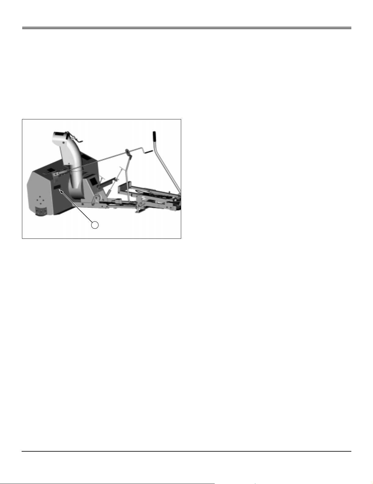
PRODUCT IDENTIFICATION
Product Identification
Record Identification Numbers
42-Inch Snowblower
Serial No. (010001-)
If you need to contact an Authorized Service Center for
information on servicing, always provide the product model
and serial number.
You will need to locate the model and serial number for the
machine and fortheengineofyour machine and record the
information in the spaces provided below.
A
DATE OF PURCHASE:
_________________________________________
DEALER NAME:
_________________________________________
DEALER PHONE:
_________________________________________
PRODUCT IDENTIFICATION NUMBER (A):
__ __ __ __ __ __ __ __ __ __ __ __ __ __ __ __ __
Product Identification
Page 4

TABLEOFCONTENTS
Tableof Contents
Contents
Safety...........................................................................................1
Assembly........................................................................................4
PreparingVehicle..................................................................................8
Installing . . . . . . . . . . . . . . . . . . . . . . . . . . . . . . . . . . . . . . . . . . . . . . . . . . . . . . . . . . . . . . . . . . . . . . . . . . . . . . . . . . . . . . . .11
Removing.......................................................................................14
Operating.......................................................................................16
ReplacementParts................................................................................22
Service ........................................................................................23
Troubleshooting ..................................................................................27
Storage.........................................................................................28
Index...........................................................................................29
All information, illustrations and
specifications in this manualare based
on the latest information at the time of
publication. The right is reserved to
make changes at any time without
notice.
COPYRIGHT© 1999
Deere & Co.
John Deere Worldwide Commercial and
Consumer Equipment Division
Horicon, WI
All rights reserved
Table of Contents
OMGX10742 J9 - English
Page 5
SAFETY
Safety
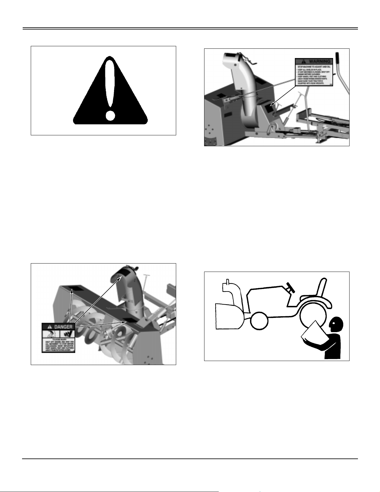
Understanding The Machine Safety Labels
The machine safety labels shown in this section are placed
in impor tant areas on your machine to draw attention to
potential safety hazards.
On your machine safety labels, the words DANGER,
WARNING, and CAUTION are used with this safety-alert
symbol, (
hazards.
The operator’s manual also explains any potential safety
hazards whenever necessary in special safety messages
that are identified with the word, CAUTION, and the safetyalert symbol, (
c). DANGER identifies the most serious
c).
WARNING
Picture Note: Decal located on pulley cover of
snowblower housing.
• Stop machine to adjust and oil.
• Keep all shields in place.
• If unit becomes clogged, shut off engine before
cleaning.
• Keep hands, feet and clothing away from power-driven
parts.
• Make sure your tractor is equipped with rear weights.
DANGER
Picture Note: One decal located on chute spout
and two on top surface of snowblower housing.
To avoid injury
• Shut off engine and wait for all movement to stop before
unclogging snow deflector.
• Keep hands, feet and clothing away from rotating auger.
Operate Safely
• Read the Tractor and Snowblower Operator’s Manual
carefully. Be thoroughly familiar with the controls and the
proper use of the equipment. Know how to stop the tractor
and disengage the controls quickly.
• Check vehiclebrake action beforeyou operate. Adjust or
service brakes as necessary.
• Inspect machine before you operate. Be sure hardware
is tight. Repair or replace damaged badly worn, or missing
parts. Be sure guards and shields are in good condition
and fastened in place. Make any necessary adjustments
Safety - 1
Page 6

SAFETY
before you operate.
• Clear work area of objects that might be thrown. Keep
people and pets out of the work area. Keep children
indoors when blowing s now. Turn the machine off if anyone
enters the area.
• If you hit an object, stop the machine and inspect it.
Make repairs before you operate. Keep machine properly
maintained and in good working order.
• DO NOT leave machine unattended when it is running.
• Only operate during daylight or with good artificial light.
• Drive up and down-not across slopes.
• DO NOT operate near edge of ditch or bank. Avoid
holes, rocks, and roots. Be alert for hidden hazards.
• Older adults are involved in a large percentage of riding
mower accidents involving injury. These operators should
evaluate their ability to operate a mower and a snowblower
safely enough to protect the operator and others from
serious injury.
Parking Safely
1. Stop machine on a level surface, not on a slope.
2. Disengage mower blades.
3. Lower attachments to the ground.
4. Lock the park brake.
5. Stop the engine.
6. Remove the key.
7. Wait for engine and all moving parts to stop before you
leave the operator’s seat.
• Look carefully behind tractor before you back up.
• DO NOT let anyone, especially children, ride on
machine or attachment. Riders are subjectto injury such as
being struck by foreign objects and being thrown off. Riders
may also obstruct the operator’s view, resulting in the
machine being operated in an u nsafe manner.
• Do not wear radio or music headphones while operating
the machine. Safe operation requires your full attention.
• DO NOT let children or an untrained person operate
machine.
• Be alert for traffic when crossing or wor king near
roadways.
• Be alert. DO NOT operate snowblower when you are
tired or ill or under the influence of drugs or alcohol.
• Keep clear of the discharge opening at all times.
• DO NOT operate tractor at high speeds. Operate
snowblowerat full throttle and a safe, slow travel speed.
• Do not throw snow toward bystanders, buildings, or
automobiles.
• Throw snow downwind, if possible.
• Clean snowblower after you use it.
• Be extremely careful if you must clear snow from a
gravel surface.
Wear Appropriate Clothing
• Always wear safety glasses or eye shields during
operation to protect eyes from foreign objects that may be
thrown from the machine.
• Wear adequate winter outer garments and footwear that
will improve footing on slippery surfaces.
• Wear close fitting clothing and safety equipment
appropriate for the job.
• Loud noise can cause impairment or loss of hearing,
wearasuitableprotectivedevicesuchasearplugs.
• Operate slowly and carefully on slopes and in sharp
turns.
Safety - 2
Page 7
SAFETY
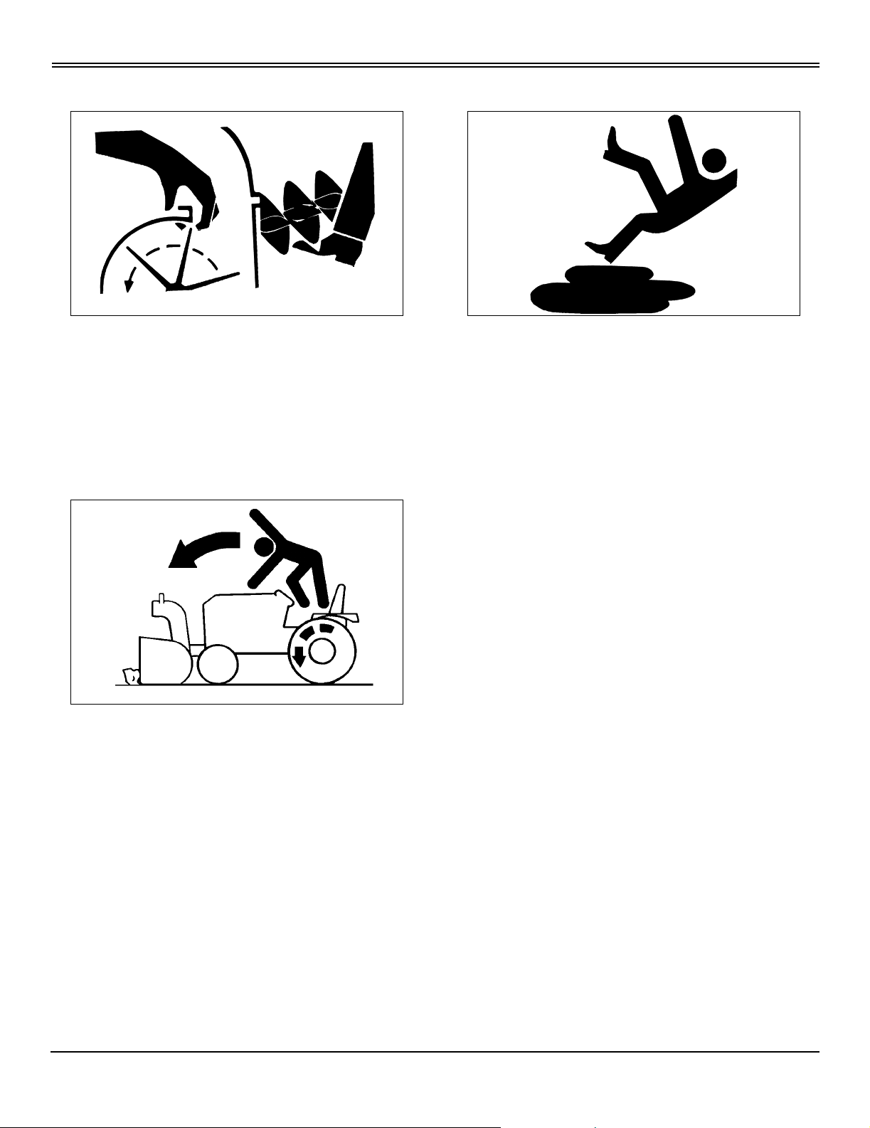
Avoid Injury from Moving Parts
• Keep hands, feet and clothing away from snowblower
and discharge chute when auger is turning.
• Stop auger when you are not throwing snow.
• Stop vehicle engine before you unplug, repair, or adjust
snowblower.
Avoid Injury from Hitting Obstructions
Practice Safe Maintenance
• Understand service procedure before doing work. Keep
area clean and dry.
• Never lubricate, service, or adjust machine while it is
moving. Keep safety devices in place and in working
condition. Keep hardware tight.
• Keep hands, feet, clothing, jewelry, and long hair away
from any moving parts, to prevent them from getting
caught.
• Lower attachments to the ground before servicing
machine. Disengage all power and stop the engine. Lock
park brake and remove the key. Let machine cool.
• Securely support any machine elements that must be
raised for serv ice work.
• Raise snowblower when you drive between jobs.
• Slow down when you remove snow. Be cautious on
slopes, when you make turns or when close to buildings or
trees.
• Never run engine unless park brake is locked.
• Keep all parts in good condition and properly installed.
Fix damage immediately. Replace worn or broken parts.
Remove any buildup of grease, oil, or debris.
• Disconnect battery negative (-) cable before making
adjustments on electrical systems or welding on machine.
• Do not modify machine. Unauthorized modifications
may impair its function and safety.
• Do not wear radio or music headphones while servicing
the machine. Safe ser vice requires your full attention.
Safety - 3
Page 8
ASSEMBLY
Assembly
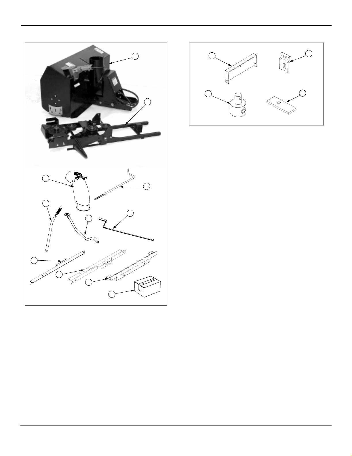
Identify Parts
C
E
BoxofParts
A
B
A
C
B
D
M95927
Qty Description Size
1 (A) Front Axle Bracket
3 (B) Anchor Stacks
1 (C) Adjustable Control Rod
Anchor
D
2 (D) Spacer Shims
1 V-Belt, Upper
F
G
2 Lift Assist Springs
2 Chain and Toggle Assembly
H
I
J
K
A - Snowblower Assembly
B - Mounting Frame Assembly
C - Discharge Chute Assembly
D - Clutch Link Rod
E - Lift Handle
F - Chute Control Support Rod
G - Chute Control Rod
H - Left-Hand Mounting Angle
I - Right-Hand Mounting Angle
J - Lift Spring Anchor Bracket
K-BoxofParts
M95926
2 Tail Reflectors
2 Clevis Pins
1 Handle Grip
2 Hair Cotter Pins 2-7/8 Lg
4 Hair Cotter Pins 1-5/8 Lg
1 CotterPin 1/8x11/4
2 Hex Nuts 1/2-13
6 Hex Head Bolts 5/16-18 x 1 3/4
2 Hex Head Bolts 3/8-16 x 1
2 Hex Head Bolts 1/2-13 x 2
9 Hex Nylock Nuts 5/16-18
4 Hex Nylock Nuts 3/18-16
2 Hex Lock N uts 1/2-13
2 Hex Head Bolts 3/8-16 x 1 1/4
2 Hex Jam Nuts 7/16-14
3 Carriage Bolts 5/16-18 x 3/4
Assembly - 4
Page 9

Assembling Snowblower
ASSEMBLY
I
E
F
E
B
F
A
C
D
C
C
1. Raise the rear of the snowblower and slide the lift
handle (A) under the channel bracket (B).
2. Place spacer shims (C) inside the rear of the mounting
channel with the short end toward the front of the
snowblower and align holes.
3. Slide mounting frame (D) inside channel bracket.
4. Check that holes in spacer shims are aligned with holes
in lower frame bar.
5. Insert 5/16 x 1 3/4-Inch bolts (E), one on each side,
through vertical hole of the lower mounting frame bar,
spacer shim, and channel bracket and secure with 5/16Inch Nylock nuts. Do not tighten at this time.
6. Insert 5/16 x 1 3/4-Inch bolts (F), two on each side,
through horizontal holes of channel bracket and lower
frame bar and secure with 5/16-Inch Nylock nuts. Tighten
nuts.
7. Tighten nuts on vertical bolts.
8. Raise the rear of the snowblower and remove the lift
handle from under it.
Picture Note: Underside of mounting frame shown
to illustrate correct routing of lower V-belt.
9. Install lower V-beltaround mounting bracket idlers and
pulley (I) as shown.
IMPORTANT: Avoid damage! Route upper V-belt
INSIDEthreebeltguides.Routingbeltincorrectly
can cause belt damage.
J
M
K
L
K
K
10.Install upper V-belt (J) to idlers as shown.
11.Check belt routing. Make sure upper V-belt is routed
INSIDE two belt guides (K) and belt guide (L).
12.Check position of belt guide (L).
• Tractors with V-Twin engines and 46-Inch mower
deck: Belt guide (L) should remain in outer hole as
shown.
• All other tractors: Move belt guide (L) to inner hole
(M).
Assembly - 5
Page 10
ASSEMBLY
Assemble Discharge Chute to Auger Housing
A
M95940
1. Loosen 3/8-Inch nut and lock washer (A) that holds
chute control cable assembly to the auger housing and
move cable down away from anchor mounts.
G
B
D
stack anchors.
NOTE: Make sure top strand coming off chute control
cable assembly goes around front of discharge chute.
9. Move the chute control cable (H) u p from the stack of
the auger housing onto the bottom of the discharge chute.
A
D
K
J
C
E
F
H
M95939
2. Insert 5/16 x 3/4-Inch carriage bolt (B) through one of
the holes in the stack (C) of the auger housing (D) with the
head of the bolt to the inside of the stack.
3. Place one stack anchor (E) onto the bolt.
4. Install 5/16-18 Nylock hex nut (F) finger tight onto bolt.
5. Install, finger tight, two other carriage bolts, stack
anchors, and Nylock nuts to the remaining two holes of the
stack.
6. Lubricate the outside of the auger housing stack (C) and
the inside of the discharge chute (G) with WD-40 or an
equivalent.
I
M95940
10.Place both loops (I) of the chute control cable over the 1/
4-Inch hex bolt and flat washer (J) on the right hand side of
the discharge chute.
11.While keeping tight pressure to the left on the chute
control cable assembly (K), remove cable tie from the
cable,slide the chute control cable assembly to the left until
cable is taut and retighten 3/8-Inch nut and lock washer (A)
assembly to secure chute control cable assembly.
M
L
M95941
7. Install discharge chute onto the stack of the auger
housing with the discharge opening facing forward.
8. Place hook of stackanchors overthe lip of the discharge
chute, push stack anchors up, pull out to seat square of
carriage bolt in hole and tighten Nylock nut at all three
Assembly - 6
12.To obtain optimum clearance and chute rotation
proceed as follows:
• Make sure discharge chute is lubricated. (See
Lubricating Discharge Chute in Service section.)
Page 11

ASSEMBLY
• If rotation difficulty continues use a screwdriver to pry
out carefully on all three of the chute clips to obtain a 1/
16 to 1/8-Inch gap between base (L) and chute clips (M)
or until chute rotates freely.
Assembly - 7
Page 12

PREPARING VEHICLE
PreparingVehicle
Install Tractor Weights and Chains
cCAUTION: Avoid injury!
The machine may become unstable when
operating with snowblower.
Use wheel weights to improve stability when
operating with snowblower.
Remove weights from tractor after snowblower
is removed.
NOTE: Before you attach snowblower, REMOVE
MOWER DECK from tractor. (See Removing and
Storing Mower section in your Tractor O perator’s
Manual.)
Rear Wheel Weights and Rear Tire Chains are
recommended for stability and traction.
• Rear Wheel Weights - Kit Part N umber BG10189
• Rear Tire Chains - Kit Part Number BG10188
Check Tire Pressure
Install Spring Anchor Bracket to Front of Tractor
A
1. Remove two s crews (A) from the front of the tractor.
2. Align holes of the spring anchor bracket (B) with the
holes of the tractor and reinstall two metric screws to
secure the spring anchor bracket.
B
M95928
Install Front Axle Bracket to Rear Side of Front Axle
IMPORTANT: Avoid damage! To prevent tire
damage, DO NOT use more than maximum tire
pressureshownonsidewalloftire.
Check tire pressure with an accurate gauge.
Add or remove air, if necessary.
Front Tire Rear Tire
100kPa(14psi) 70kPa(10psi)
Check Tractor Engine Oil and Battery
Refer to your Tractor Operator’s Manual for Cold Weather
Starting procedures.
C
B
A
M95929
1. Remove 10mm nut and washer (A) from the rear of the
tractor front axle.
2. Position the front axle bracket (B) over the exposed bolt
with the flanged edges toward the rear of the tractor.
3. Secure the front axle bracket to the front axle (C) with
the 10mm nut and washer.
Preparing Vehicle - 8
Page 13

Install Mounting Angles
2
PREPARING VEHICLE
B
A
C
D
M9593
1. Assemble 1/2-Inch standard nut (A) onto 1/2 x 2-Inch
hex bolt (B) and run it down to the end of the treads.
2. Lock the nut in place with two wrenches.
F
E
H
J
G
I
M95930
8. Insert 3/8 x 1 1/4-Inch bolt (G) down through mower
mounting bracket of tractor (H), through 7/16-Inch jam nut
(I) used as spacer, through mounting angle, then secure
with 3/8-Inch Nylock nut (J).
9. Install a mounting angle to the other side of the tractor
using the same procedure as first mounting angle.
10.Tighten securely the finger tight bolt and nut at each
side of the front axle bracket.
Install Clutch Link Rod to Tractor
C
B
M95931
3. At the rear end of one mounting angle (C) insert 1/2 x 2Inch bolt into hole.
4. Secure with 1/2-Inch lock nut (D).
5. Install 1/2 x 2-Inch bolt with 1/2-Inch standard nut and
1/2-Inch lock nut into same hole of other mounting angle
using same procedure as above.
6. Insert 3/8 x 1-Inch bolt (E) through from the inside of the
frontaxlebracket(F).
7. Place mounting angle over end of 3/8 x 1-Inch bolt and
secure finger tight with 3/8-Inch Nylock nut.
C
E
A1
A
B
1. Pre-adjust clutch link rod (A) to approximately 384 mm
(15 In.) (A1) from the center of the bent end of the clutch
rod to t he center of the adjustable anchor (B).
2. Insert 1/8 x 1 1/4-Inch cotter pin (C) into hole nearest
thebendoftheclutchrodandspreadendstosecure.
D
E
A
Preparing Vehicle - 9
3. Insert bent end of clutch link rod up into the hole in the
tractor attachment engagement lever (D). S ecure with hair
Page 14

PREPARING VEHICLE
cotter pin (E).
4. Temporarily lay adjustable end of clutch link rod on top
of the left side mounting angles until you are ready to
attach to the snowblower.
Install Reflective Tape
A
Apply two reflectors (A), one on each side of rear hitch
plateandaminimumof305mm(12in.)fromtheground.
M95935
Preparing Vehicle - 10
Page 15

INSTALLING
Installing
Place Tractor Over Snowblower Frame
cCAUTION: Avoid injury! Attachment is heavy.
Keep hands and feet out from under attachment
when removing or installing.
1. Park machine safely. (See Parking Safely in the Safety
Section).
2. Move the tractor mower lift handle to the raised position.
3. Position snowblower directly in front of t he tractor.
A
sliding rear slots of upper mounting frame onto 1/2 x 2-Inch
bolts (B) protr uding from mounting angles of tractor.
Install Upper V-Belt
cCAUTION: Avoid injury! The engine may
accidently start while servicing the machine.
Remove the key and disconnect any spark plug
wires before servicing.
IMPORTANT: Avoid damage! Route upper V-belt
INSIDEthreebeltguides.Routingbeltincorrectly
can cause belt damage.
1. Move tractor attachment lever into disengaged (OFF)
position.
A
B
M95942
4. Roll tractor forward until right front tire makes contact
with the lift bar (A).
5. Roll right front tire by hand forward over lift bar.
Attach Upper Mounting Frame
B
A
M95943
D
C
B
2. Check belt routing. Make sure that upper V-beltis routed
INSIDE the clutch idler pulley (A), two belt guides (B) and
belt guide (C).
3. Check position of belt guide (C).
• Tractors with V-Twin engines and 46-Inch mower
deck: Belt guide (C) should remain in outer hole as
shown.
• All other tractors: Move belt guide (D) to inner hole
(M).
1. Position upper mounting frame (A) in line with tractor
frame.
2. Move snowblower lift bar rearward to the raised position.
3. Lift rear of upper mounting frame and roll tractor forward
Installing - 11
Page 16

INSTALLING
Set Lower V-Belt Tension
F
E
4. Move belt guide (E) and roll upper V-belt around tractor
engine drive pulley (F).
Attach Lower Mounting Frame to Tractor
1. Move snowblower lift bar forward to the lowered
position.
2. Slide snowblower lift handle under rear of lower
mounting frame and lift up to raise front mounting brackets
into clevises of mounting angles.
C
A
B
B
A
Pull tensioning chain (A) to tighten lower V-belt and secure
with hair cotter pin (B).
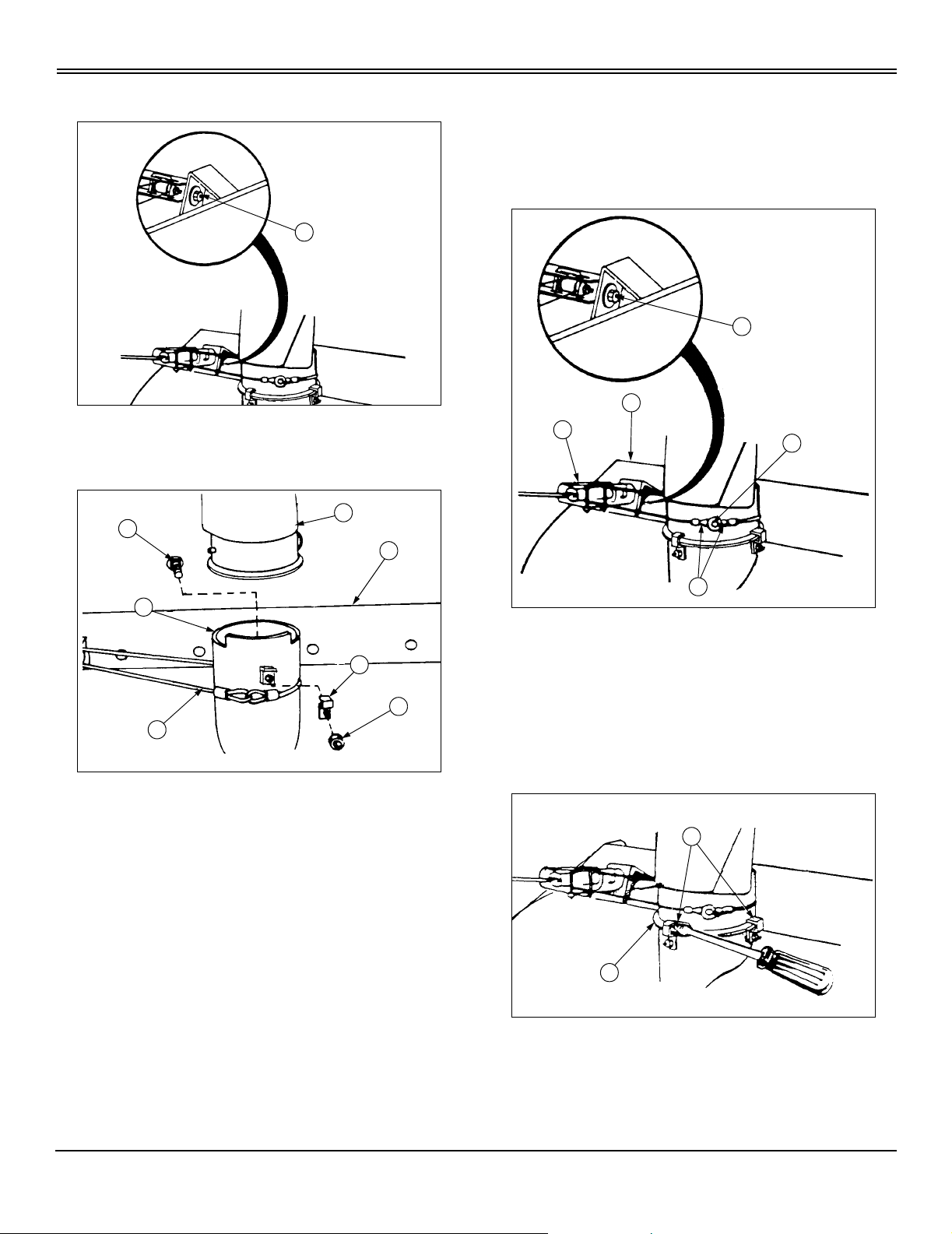
Install Clutch Link Rod
1. Place the tractor attachment lever in the disengaged
(OFF) position.
D
A
3. Align the hole in the front mounting brackets (A) with
hole in mounting angle clevis (B) and secure with clevis pin
andhaircotterpins(C).
4. Remove the lift handle from under the snowblower.
C
B
2. Move idler arm (A) to the left side of the snowblower
frame and hold against the stop.
3. Adjust the length of the clutch link rod (B) until the
mounting anchor (C) can be assembled into the clutch bell
crank.
4. Attach clutch rod link with hair cotter pin (D).
Installing - 12
Page 17

INSTALLING
Install Lift Handle
A
B
1. Slide the lift handle (A) over the end of the lift bar (B)
with the grip offset toward the operator’s position of the
tractor.
2. Adjust lift height.
Install Lift Assist Springs
6. If chain and spring are not taunt, remove the hair cotter
pin, apply a little more pressure and reinstall the hair cotter
pin.
7. Assemble lift assist spring on other side of tractor using
the same procedure.
Install Chute Control Support
C
F
B
A
E
D
1. Pull lift handle back to place snowblower in the raised
position.
B
A
C
D
E
2. Thread the chain and toggle assembly (A) through the
spring anchor bracket (B) mounted on the front of the
tractor.
3. Hook one end of the lift assist spring (C) into the hole of
the channel box bracket (D) and the other end into the last
link of t he chain and toggle.
4. Pull the toggle end of the chain and toggle, exerting
slight pressure on lift assist spring.
1. Assemble chute control rod (A) crank handle through
hole in chute control support (B) from the back side of the
decal plate.
2. Hook the loop of the chute control rod into the eyebolt of
the chute level wind assembly (C).
3. Loosen chute control support bolt (D).
4. Place chute control support over post on chute control
support bracket (E).
5. Tighten chute control support bolt into hole in post.
6. Slide plastic handle grip (F) onto handle of chute control
rod.
5. Insert large hair cotter pin (E) through chain just above
thespringanchorbracket.
Installing - 13
Page 18

REMOVING
Removing
Removing Snowblower
cCAUTION: Avoid injury! Attachment is heavy.
Keep hands and feet out from under attachment
when removing or installing.
NOTE: Store all hair cotter pins and clevis pins in
snowblower assembly for storage.
1. Park machine safely. (See Parking Safely in the Safety
Section).
B
E
4. Lower snowblower and remove lift handle (E).
A
2. Loosen chute control support bolt(A) then removechute
control support and chute control rod (B) as one assembly.
D
C
3. R aise snowblower and remove lift assist spring (C)
along with chain and toggle (D) from each side of unit.
F
5. Disconnect clutch link rod (F) from tractor attachment
engagement lever.
H
G
6. Remove upper V-belt from engine drive pulley (G).
7. Use lift handle to relieve weight from clevis pins (H) and
remove hair cotter pins and clevis pins from front mounting
brackets. Lower upper mounting frame to ground.
Removing - 14
Page 19

REMOVING
J
I
8. Roll tractor forwardcarefully until rear of upper mounting
frame (I) can be lowered from 1/2 x 2-Inch bolts (J) in
mounting angles.
cCAUTION: Avoid injury! When the snowblower
is removed, remove any weights that were
added to the tractor.
12.Removeany weights that were installed when preparing
the tractor.
M95942
9. Roll tractor backward off of the snowblower .
M
K
L
10.Remove both left hand and right hand mounting angles
(K) from tractor. Replace hardware (L) into holes of
mounting angles for storage.
11.Front axle bracket (M) and spring anchor bracket may
be left mounted to tractor is desired.
M95931
Removing - 15
Page 20

OPERATING
Operating
Before Operating Snowblower
• Learn all controls and how they work. Read your
Tractor's O perator Manual, if necessary.
•STOPengine.
• LOCK park brake.
•Removekey.
• Make operating adjustments as necessary.
• Tighten loose hardware.
Daily Operating Checklist
Check snowblower for loose fasteners.
Lubricate discharge chute.
Controls and Adjustment Levers
B
A
C
D
Snowblowing Tips
Install tire chains and rear weights on tractor.
Adjust runners before you clear snow.
Operate snowblower at full throttle.
Operate snowblower at safe, SLOW travel speed.
Slow down:
• On slopes.
• When you make turns.
• When you throw snow close to buildings or trees.
Always transport with the snowblower in the RAISED
position and the attachment clutch lever DISENGAGED.
Throw snow downwind, if possible.
If you hit an object:
• STOP snowblower immediately.
• Fix damage before you use snowblower again.
Before you clean or unplug snowblower:
E
• Move attachment clutch lever to the DISENGAGED
position.
• STOP engine.
J
K
F
I
H
A - Snow Deflector
B - Snow Deflector Control Handle
C - Snowblower Lift Handle
D - Attachment Clutch Lever
E - Chute Control Rod
F - Lift Assist Springs
G - Skid Shoes
H - Scraper
I - Snow Augers
J - Auger Housing
K - Discharge Chute
• Remove key.
• LOCK park brake.
• Wait for ALL moving parts to STOP.
• Lower snowblower to the ground.
• Remove spark plug wires.
• Clean snowblower after you use it.
G
Stopping Tractor and Snowblower
When stopping tractor, do the following:
1. Depress clutch/brake pedal fully.
2. Put transmission in NEUTRAL position.
Operating - 16
Page 21

OPERATING
Adjusting Chute
A
B
C
M95964
3. Pull back on attachment clutch lever(A) to DISENGAGE
auger.
4. Lower snowblower to ground.
5. STOP engine.
6. LOCK park brake (B).
7. Remove key (C).
Raising and Lowering Snowblower
A
M95958
The snowblower has a discharge radius of 240 degrees
and is controlled by the chute control rod. The discharge
chute stop bolt will prohibit rotation beyond this point.
A
Turn chute control rod (A) to the right to direct snow to the
right side of the tractor and to the left for the opposite effect.
To adjust chute rotation see Adjusting Discharge Chute
Drive Tube in Service section.
To RAISE snowblower: Pull lift handle (A) all the way back.
To LOWER snowblower: Push lift handle (A) all the way
forwardandlowersnowblowertogroundlevel.
Operating - 17
Adjusting Distance of Snow Discharge
A
The distance snow will be discharged can be adjusted by
B
Page 22

OPERATING
moving the snow deflector (A).
To increase distance snow is discharged, pull down on
snow deflector control handle (B) and lock in position.
Adjusting Lift Height
cCAUTION: Avoid injury! Rotating auger is
dangerous.
Before making adjustment:
• Park the machine safely and lock the park
brake before getting off the seat.
• Turn the snowblower off.
• Stop the engine.
• Wait for all moving parts to stop.
B
not, repeat process.
Adjusting Lift Assist Springs
cCAUTION: Avoid injury! Rotating auger is
dangerous.
Before making adjustment:
• Parkthemachinesafelyandlockthepark
brake before getting off the seat.
• Turn the snowblower off.
• Stop the engine.
• Wait for all moving parts to stop.
The lift assist springs (A) help in carrying the weight of the
snowblower.
For extra scraping ability in packed or hardened snow,
reduce tension of lift assist springs.
C
A
M95955
1. Place snowblower on ground level.
2. Loosen jam nut (A) and turn lift height adjustment bolt
(B):
• RIGHT to INCREASE lift height
• LEFT to DECREASE lift height
3. Raise snowblower and recheck lift height.
C
A
1. Put snowblower in the raised position and pull up on
chain and toggle (B) and remove hair cotter pin (C).
D
B
4. If up stop (C) hits front tractor axle retighten jam nut. If
Operating - 18
2. Allow severallinks of chain to pass down through hole in
thespringanchorbracket(D)andreplacehaircotterpin
justabovethespringanchorbracket.
• To decrease scraping action when snowblower is
Page 23

used on rough surfaces, increase tension o n lift assist
spring by removing hair cotter pin and pulling several
links up through hole in spring anchor bracket and
replacing hair cotter pin.
3. Adjust chain and toggles evenly.
Adjusting Skid Shoes
OPERATING
A
cCAUTION: Avoid injury! Rotating auger is
dangerous.
Before making adjustment:
• Park the machine safely and lock the park
brake before getting off the seat.
• Turn the snowblower off.
• Stop the engine.
• Wait for all moving parts to stop.
IMPORTANT: Avoid damage! Both the scraper and
skid shoes are subject to wear and are designed for
easy replacement. Replace before wear is excessive
to prevent damage to the auger housing or snow
auger.
The skid shoe mounted on each side of the header housing
adjusts the distance the scraper blade is raised above the
surface.
• When removing snow from an uneven surface or a
gravel driveway, it is advisable raising scraper as high
above the surface as possible to prevent possible damage
to the snow auger and to help prevent stones from being
thrown with snow.
• On blacktop or concrete, keep the scraper as close to
the scraping surface as possible.
AdjustingSkidShoesforUseonGravelDrivewaysor Uneven Surfaces
NOTE: Make sure both skid shoes are adjusted to keep
scraper level even with scraping surface.
1. Place snowblower in raised position.
2. Place 2 x 4 blocks under both ends of the scraper.
3. Lower snowblower scraper onto blocks.
M95957
4. Loosen six nuts (A) on the inside of the auger housing
which secure the skid shoes.
5. Allow skid shoes to drop to the ground.
6. Retighten six nuts securing skid shoes.
7. Lower snowblower to the ground.
Adjusting Skid Shoes for Use on Concrete or Even Surfaces
1. Place snowblower in raised position.
2. Loosen six nuts (A) on the inside of auger housing
which secure the skid shoes.
3. Lower snowblower to ground level.
4. Retighten six nuts to secure skid shoes.
Unplugging Discharge Chute
cCAUTION: Avoid injury! Rotating auger is
dangerous.
• Parkthemachinesafelyandlockthepark
brake before getting off the seat.
• Turn the snowblower off.
• Stop the engine.
• Wait for all moving parts to stop.
• Disconnect spark plug wire(s) to prevent
engine from starting accidently.
If snowblower becomes plugged with snow or jammed due
to hitting an obstruction, proceed as follows:
Operating - 19
Page 24

OPERATING
Operating Snowblower
cCAUTION: Avoid injury! Thrown objects can be
dangerous. Before you operate snowblower:
Clear area of bystanders and pick up objects
A
B
1. Turn discharge chute control rod to desired direction of
discharge.
2. Move snow deflector to desired discharge distance.
which may be thrown by snowblower.
1. STOP tractor.
2. Pull back on attachment clutch lever (A) to
DISENGAGE.
3. STOP the engine.
4. LOCK the park brake (B).
5. Remove the key (C).
6. Wait for auger to STOP.
7. Lower snowblower to the ground.
8. Remove spark plug wires.
C
M95964
D
3. Start engine.
A
M95964
4. Put throttle lever (A) to FAST (r) position.
5. Move attachment clutch lever forward to ENGAGED
position.
6. Push forwardon lift handle and lower snowblowerto the
ground.
9. Remove lift handle (D) and use it to push snow back
down into auger housing.
10.Reassemble lift handle.
11.Replace spark plug wires.
12.Resume snow removal.
IMPORTANT: Avoid damage! For best snowblower
and engine performance, operate engine at FULL
THROTTLE when blowing snow.
7. Select lowest tractor ground speed at tractor full throttle
and engage tractor ground drive.
Transporting
IMPORTANT: Avoid damage! Always lower
snowblower to trailer deck when transporting.
1. Drive tractor and snowblower onto heavy-duty trailer.
Operating - 20
Page 25

OPERATING
2. LOWER snowblower to trailer deck.
3. STOP engine.
4. LOCK park brake.
5. Fasten tractor and snowblower to deck with straps,
chains, or cables.
6. Trailer must have lights and signs required by law.
Operating - 21
Page 26

REPLACEMENT PARTS
ReplacementParts
Service Literature
If you would like a copy of the Parts Catalog or Technical
Manual for this machine call:
• U.S. & Canada: 1-800-522-7448.
• All Other Regions:YourJohnDeeredealer.
Parts
WE RECOMMEND quality parts and lubricants, available
at your Authorized Service Center.
PART NUMBERS MAY CHANGE, use part numbers listed
below when you order. If a number changes, your service
center will have the latest number.
WHEN YOU ORDER PARTS, your service center needs
your machine serial number and engine serial number.
Thesearethenumbersthatyouhaverecordedonthe
inside front cover of this manual.
ITEM PART NUMBER
Upper V-Belt GXH24570
Lower V-Belt GXH24522
Skid Shoes GXH3045
Scraper Blade GXH24499
(Part numbers are subject to change without notice. Part
Numbers may be different outside the U.S.A.)
Replacement Parts - 22
Page 27

SERVICE
Service
Service Intervals
Before Each Use Check unit for loose fasteners.
Lubricate discharge chute.
Every10HoursorEachYear Lubricate all zerks.
Lubricate auger bearings.
Lubricate discharge chute.
Lubricate lift bar.
Check and adjust lift height.
Check skid shoes and scraper blade and replace if necessary.
Check V-belts and replace if worn.
Check snow auger and straighten if necessary.
As Required Check discharge chute drive tube.
Check lift assist springs.
Lubricants
The following lubricants are preferred:
• Light Machine Oil (SAE30 API-S6)
• General Purpose Grease
• WD-40 or equal
Lubricate Lift Bars
Check skid shoes.
Lubricate Vertical Jack Shaft
A
Lubricate vertical jack shaft zerk (A) with General Purpose
A
Grease.
Lubricate lift bars (A) with Light Machine Oil (SAE30
APIS6).
Service-23
Page 28

SERVICE
Lubricate Auger
B
C
A
Lubricate auger bearings (A), auger tubes (B), and
discharge fan (C) with General Purpose Grease.
B
Lubricate Discharge Chute
A
bolt (A).
B
A
M95959
• Tighten lock nut (B) 1/8 turn and check rotation of
discharge chute dr ive tube by turning chute control rod.
• A small amount of resistance should be encountered.
DO NOT overtighten. Tighten until discharge chute holds
its position.
Chute Control Cable Hook-Up
Chute control cable is wound around discharge chute drive
tube 2 1/2 turns each way; both ends of equal length. This
will allow equal angle of discharge chute in both directions.
Lubricate discharge chute (A) with WD-40 or equivalent.
Adjusting Discharge Chute Drive Tube
cCAUTION: Avoid injury! Rotating auger is
dangerous.
• Park the machine safely and lock the park
brake before getting off the seat.
• Turn the snowblower off.
• Stop the engine.
• Wait for all moving parts to stop.
• Disconnect spark plug wire(s) to prevent
engine from starting accidently.
If discharge chute will not hold its position and tends to
rotate, adjust lock nut on end of discharge chute tube eye
Replacing Upper V-Belt
1. Remove the snowblower from the tractor, if necessary.
2. Remove damaged V-belt.
3. Install new V-belt on upper idlers as shown.
Service-24
Page 29

SERVICE
IMPORTANT: Avoid damage! Route upper V-belt
INSIDE three belt guides. Routing belt incorrectly
can cause belt damage.
A
B
K
B
B
4. Check belt routing. Make sure that upper V-beltis routed
INSIDE the clutch idler pulley (A) and three belt guides (B).
5. Reassemble snowblower to the tractor.
B
2. Remove the drive pulley guard (B) from the auger
housing.
3. Roll lower V-belt off of jack shaft pulley, idlers and
mounting bracket pulley and remove it from the
snowblower.
Replacing Lower V-Belt
NOTE: It is not necessary to remove the snowblower
for this procedure. The snowblower was removed for
illustration only.
A
1. Remove hair cotter pin from belt tensioner (A) and
loosen lower V-belt tension.
D
C
4. Install new V-belt under two idler pulleys (C) and roll it
around the jack shaft pulley (D) inside the auger housing.
Service-25
Page 30

SERVICE
E
Picture Note: Underside of mounting frame shown
to illustrate correct routing of lower V-belt.
5. Assemble new lower V-belt around mounting bracket
pulley and idlers (E) as shown.
6. Install the drive pulley guard to the rear of the auger
housing.
7. Set lower V-belt tension.
Service-26
Page 31

TROUBLESHOOTING
Troubleshooting
Using Troubleshooting Chart
If you are experiencing a problem that is not listed in this
chart, see your authorized service center dealer for service.
Whenyouhavecheckedallthepossiblecauseslistedand
you are still experiencing the problem, see your authorized
service center.
IF CHECK
Auger Housing Vibration Failed bearing. (See your Authorized Service Center.)
Lower V-Belt Fluttering Lower V-belt too loose.
No grease on J-shaft housing zerk.
Clogged Discharge Chute Tractor ground speed too fast.
Not operating with tractor at FULL throttle.
Snow too deep.
Discharge Chute is Difficult to Rotate or Will Not Hold
Position
Snowblower Does Not Operate Upper or lower V-belt not in pulley grooves.
Burned Rubber Smell Worn or broken V-belt.
Snowblower Will Not Lift Adjusting bolt in too far.
SnowblowerKills Tractor Engine Object jammed in snow auger or discharge fan.
Discharge chute drive tube nut too loose.
Chute control cable too loose.
Discharge chute and stack ring are dry.
Worn or broken V-belt.
Broken shear bolt.
Upper V-belt outside of belt retainers.
V-belts not in pulley grooves.
Object jammed in snow auger or discharge fan.
Object jammed between upper and lower mounting frame.
Very hard or heavy snow.
Very wet snow.
Troubleshooting - 27
Page 32

STORAGE
Storage
Storing Snowblower
Remove snowblower from tractor.
Clean the snowblower with standard garden hose.
Check V-belts, snow auger chain, scraper blade, and skid
shoes and replace if worn. Do not install new belts until you
take snowblower out of storage.
If possible, store snowblower indoors on hard, level surface.
If you store snowblower outside:
• Put blocks or a board under snowblower.
• Cover snowblower with a waterproof cover.
Inspect snowblower. Repair or replace badly worn or
damaged parts.
Apply touch-up paint where needed to prevent rust.
Lubricate snowblower.
Storage - 28
Page 33

INDEX
Index
A
Angles, Install Mounting ........................................9
Auger, Lubricate ...................................................24
B
Battery, Check Tractor Engine Oil and ...................8
Bell Crank, Install Clutch Link Rod to Clutch .....12
Belt, Install Upper .................................................11
Belt, Replacing Lower ..........................................25
Belt, Replacing Upper ...........................................24
Belt, Set Lower V-belt Tension ............................12
Bracket to Front of Tractor, Install Spring Anchor .8
Bracket to Rear Side of Front Axle, Install Front Axle
8
C
Chains, Install Tractor Weights ..............................8
Chains, Install Tractor Weights and ........................8
Chute Control Support to Frame, Install ...............13
Chute Drive Tube, Adjusting Discharge ...............24
Chute to Auger Housing, Assemble Discharge ......6
Chute, Adjusting ...................................................17
Chute, Lubricating Discharge ...............................24
Chute, Unplugging Discharge ...............................19
Clutch Link Rod to Clutch Bell Crank, Install .....12
Clutch Link Rod to Tractor, Install .........................9
Controls and Adjustment Levers ..........................16
D
Discharge Chute, Unplugging ...............................19
Discharge, Adjusting Distance of Snow ...............17
F
Frame to Tractor, Attach Lower Mounting ...........12
Frame to Tractor, Attach Upper Mounting ...........11
H
Handle, Install Lift ................................................13
Height, Adjusting Lift ...........................................18
L
Labels, Safety ..........................................................1
Levers at Operator Station ....................................16
Lift Assist Springs, Adjusting ...............................18
Lift Bars, Lubricate ...............................................23
Lift Handle, Install ................................................13
Lift Height, Adjusting ...........................................18
Lubricants .............................................................23
Lubricate Auger ....................................................24
Lubricate Lift Bars ................................................23
Lubricate Vertical Jack Shaft Zerk .......................23
Lubricating Discharge Chute ................................24
M
Mounting Angles, Install ........................................9
O
Oil and Battery, Check Tractor Engine ..................8
Operating Checklist, Daily ...................................16
Operating Safety .....................................................1
Operating Snowblower ...................................16, 20
P
Parts for Assembly ..................................................4
Parts, Replacement ................................................22
R
Raising and Lowering Snowblower ......................17
Reflective Tape, Install .........................................10
Rod to Clutch Bell Crank, Install Clutch Link .....12
Rod to Tractor, Install Clutch Link .........................9
S
Safety Decals ..........................................................1
Safety, Operating ....................................................1
Safety, Service Machine .........................................3
Safety-Alert Symbol; Labels, Safety ......................1
Service Intervals ...................................................23
Service Literature; Literature, Service; Parts Catalog;
Technical Manual .................................................22
Service Parts .........................................................22
Shaft Zerk, Lubricate ............................................23
Shoes, Adjusting Skid ...........................................19
Skid Shoes, Adjusting ...........................................19
Snowblower Assembly ...........................................5
Snowblower Frame, Installing ..............................11
Snowblower, Before Operating ............................16
Snowblower, Operating ........................................20
Snowblower, Raising and Lowering .....................17
Snowblower, Removing ........................................14
Snowblower, Stopping Tractor and ......................16
Snowblower, Storing ............................................28
Snowblowing Tips ................................................16
Spring Anchor Bracket to Front of Tractor, Install 8
Springs, Adjusting Lift Assist ...............................18
Springs, Install Lift Assist ....................................13
Stopping Tractor and Snowblower .......................16
Storing Snowblower .............................................28
Index - 29
Page 34

T
Tape, Install Reflective .........................................10
Tire Pressure, Check ...............................................8
Transporting ..........................................................20
Troubleshooting Chart ..........................................27
W
Weights and Chains, Install Tractor ........................8
INDEX
Index - 30
Page 35

QUALITY STATEMENT
QualityStatement
Your product, designed and built by John Deere, is more
than just a purchase, it’s an investment in quality. That
quality goes beyond our equipment to your dealer’s parts
and service support.
That’s why John Deere has initiated a process to handle
your questions or problems, should they arise. If you have
questions or problems w ith your new product, please follow
the steps below.
To locate your nearest authorized servicing dealer, please
call the toll free number listed in your Tractor Operator’s
Manual.
Step 1
Refer to your operator’s manual
A. It has many illustrations and detailed information on the
safe and proper operation of your equipment.
B. It gives troubleshooting procedures, and specification
information.
C. It gives ordering information for parts catalogs, service
and technical manuals.
D. If your questions are not answered in the operator’s
manual,thengotoStep2.
Step 2
Contact your dealer
A. Your authorized servicing dealer has the responsibility,
authority, and ability to answerquestions, resolveproblems,
and fulfill your parts and service needs.
B. First, discuss your questions or problems with your
dealer’s trained parts and service staff.
C.If the parts and service people are unable to resolve your
problem, see the dealership manager or owner.
D. If your questions or problems are not resolved by the
dealer,thengotoStep3.
Step 3
Call the Customer Communications Center
A. Your authorized servicing dealer is the most efficient source in addressing any concern, but if you are not able to
resolve your problem after checking your operator’s manual and contacting your dealer, call the Customer
Communications Center.
B. For prompt, effective service, please have the following ready before you call:
• The name of the dealer with whom you’ve been working.
• Your equipment model number.
• Number of hours on machine (if applicable).
C. Then refer to your Tractor Operator’s Manual to locate the Customer Communications Center toll free number and call
our advisor who will work with your dealer to investigate your concern.
• Your 13-digit serial number which you recorded on the
inside front cover of this manual.
• If the problem is with an attachment, your attachment
identification number.
Quality Statement - 31
 Loading...