

Page 1
ST0521M
ST0521E
Snow Thrower
OPERATOR’S
MANUAL
MTF-031039C
Page 2

INTRODUCTION
Congratulations on your purchase of a Frontier Snowthrower. It has been designed, engineered and manufactured to give you
the best possible dependability and performance. However, like all mechanical products, your machine will occasionally require adjustment and maintenance. This handbook should be read before operating or performing and adjustments on your
machine.
The instructions in this Owner’s Manual are written for a person with some mechanical ability. Like most service books, not
all the steps are described. Steps on how to loosen or tighten fasteners are steps anyone can follow with some mechanical
ability. Read and follow these instructions before you use the unit.
Know your product:: If you understand the unit and how the unit operates, you will get the best performance. As you read
this manual, compare the illustrations to the unit. Learn the location and the function of the controls. To help prevent an accident, follow the operating instructions and the safety rules. Keep this manual for future reference.
IMPORTANT: Many units are not assembled and are sold in cartons. It is the responsibility of the owner to make sure the as-
sembly instructions in this manual are exactly followed. Other units are purchased in an assembled condition. On assembled
units, it is the responsibility of the owner to make sure the unit is correctly assembled. The owner must carefully check the unit
according to the instructions in this manual before it is first used.
The warranty, found in this manual, details the coverage and limitations of this product. Registration of the warranty is
necessary and must be preformed by the dealer within sixty (60) days from the date of retail sale or delivery. The
Warranty Registration Form is located on the Frontier website.
RESPONSIBILITY OF THE OWNER
The responsibility of the owners to follow the instructions below.
1. Carefully read and follow the rules for safe operation.
2. Follow all the assembly instructions.
3. Inspect the unit.
4. Make sure that the operator of the unit knows how to correctly use all standard and accessory equipment.
5. Operate the unit only with guards, shields, and other safety items in place and working correctly.
6. Correctly adjust the unit.
7. Service the unit only with authorized or approved replacement parts.
8. Complete all maintenance on the unit.
PRODUCT INFORMATION
The owner must be certain that all the product information is included with this unit.
This information includes the INSTRUCTION BOOKS, the REPLACEMENT PARTS
and the WARRANTIES. This information must be included to make
sure state laws and other laws are followed.
Read And Keep This Book For
Future Reference. This Book Contains Important Information On:
SAFETY, ASSEMBLY, OPERATION AND MAINTENANCE.
MTF-031039C
2
Page 3
RULES FOR SAFE OPERATION
IMPORTANT
WARNING: Always disconnect the spark plug wire and place it where it cannot make contact with
spark plug to prevent accidental starting during: Preparation, Maintenance, or Storage of your
snowthrower.
Safe Operation Practices for Snowthrowers
As Recommended By: American National Standards Institute.
Engine Exhaust, some of its constituents, and
certain vehicle components contain or emit
chemicals known to the State of California to
cause cancer and birth defects or other reproductive harm.
Battery posts, terminals and related accessories contain lead and lead compounds, chemicals known to the State of California to cause
cancer and birth defects or other reproductive
harm. WASH HANDS AFTER HANDLING.
IMPORTANT: Safety standards require operator presence
controls to minimize the risk of injury. Your snowthrower is
equipped with such controls. Do not attempt to defeat the
function of the operator presence control under any circumstances.
Training
1. Read the operating and service instruction manual carefully. Be thoroughly familiar with the controls and the
proper use of the equipment. Know how to stop the unit
and disengage the controls quickly.
2. Never allow children to operate the equipment. Never
allow adults to operate the equipment without proper
instruction.
3. Keep the area of operation clear of all persons, particularly small children and pets.
4. Exercise caution to avoid slipping or falling especially
when operating in reverse.
Preparation
1. Thoroughly inspect the area where the equipment is to
be used and remove all doormats, sleds, boards, wires,
and other foreign objects.
2. Disengage all clutches before starting the engine
(motor).
3. Do not operate the equipment without wearing adequate
winter outer garments. Wear footwear that will improve
footing on slippery surfaces.
4. Handle fuel with care; it is highly flammable.
MTF-031039C
a. Use an approved fuel container.
b. Never remove fuel tank cap or add fuel to a running en-
gine (motor) or hot engine (motor).
c. Fill fuel tank outdoors with extreme care. Never fill fuel
tank indoors.
d. Replace fuel cap securely and wipe up spilled fuel.
e. Never store fuel or snowthrower with fuel in the tank
inside of a building where fumes may reach an open
flame or spark.
f. Check fuel supply before each use, allowing space for
expansion as the heat of the engine (motor) and/or sun
can cause fuel to expand.
5. For all units with electric starting motors use electric
starting extension cords certified CSA/UL. Use only with
a receptacle that has been installed in accordance with
local inspection authorities.
6. Adjust the snowthrower height to clear gravel or crushed
rock surface.
7. Never attempt to make any adjustments while the engine (motor) is running (except when specifically recommended by manufacturer).
8. Let engine (motor) and snowthrower adjust to outdoor
temperatures before starting to clear snow.
9. Always wear safety glasses or eye shields during operation or while performing an adjustment or repair to protect eyes from foreign objects that may be thrown from
the snowthrower.
Operation
1. Do not operate this machine if you are taking drugs or
other medication which can cause drowsiness or affect
your ability to operate this machine.
2. Do not use this machine if you are mentally or physically
unable to operate this machine safely.
3. Do not put hands or feet near or under rotating parts.
Keep clear of the discharge opening at all times.
4. Exercise extreme caution when operating on or crossing
gravel drives, walks or roads. Stay alert for hidden hazards or traffic.
5. After striking a foreign object, stop the engine (motor),
remove the wire from the spark plug, thoroughly inspect
snowthrower for any damage, and repair the damage
before restarting and operating the snowthrower.
6. If the unit should start to vibrate abnormally, stop the
engine (motor) and check immediately for the cause.
Vibration is generally a warning of trouble.
3
Page 4
RULES FOR SAFE OPERATION
7. Stop the engine (motor) whenever you leave the operating position, before unclogging the auger/impeller housing or discharge chute and when making any repairs,
adjustments, or inspections.
8. When cleaning, repairing, or inspecting, make certain
the auger/impeller and all moving parts have stopped
and all controls are disengaged. Disconnect the spark
plug wire and keep the wire away from the spark plug to
prevent accidental starting.
9. Take all possible precautions when leaving the snowthrower unattended. Disengage the auger/ impeller, stop
engine (motor), and remove key.
10.Do not run the engine (motor) indoors, except when
starting the engine (motor) and for transporting the
snowthrower in or out of the building. Open the outside
doors; exhaust fumes are dangerous (containing CARBON MONOXIDE, an ODORLESS and DEADLY GAS).
11.Do not clear snow across the face of slopes. Exercise
extreme caution when changing direction on slopes. Do
not attempt to clear steep slopes.
12.Never operate the snowthrower without proper guards,
plates or other safety protective devices in place.
13.Never operate the snowthrower near enclosures, automobiles, window wells, drop- offs, and the like without
proper adjustment of the snow discharge angle. Keep
children and pets away.
14.Do not overload the machine capacity by attempting to
clear snow at too fast a rate.
15.Never operate the machine at high transport speeds on
slippery surfaces. Look behind and use care when backing up.
16.Never direct discharge at bystanders or allow anyone in
front of the unit.
17.Disengage power to the collector/impeller when snowthrower is transported or not in use.
18.Use only attachments and accessories approved by the
manufacturer of the snowthrower (such as tire chains,
electric start kits, ect.).
19.Never operate the snowthrower without good visibility or
light. Always be sure of your footing and keep a firm
hold on the handles. Walk;never run.
20.Do not over- reach. Keep proper footing and balance at
all times.
21.Exercise caution if operating on steep sloping surfaces.
22.This snowthrower is for use on sidewalks, driveways
and other ground level surfaces.
23.Do not use the snowthrower on surfaces above ground
level such as roofs of residences, garages, porches or
other such structures or buildings.
MTF-031039C
Maintenance And Storage
1. Check shear bolts and other bolts at frequent intervals
for proper tightness to be sure the equipment is in safe
working condition.
2. Never store the snowthrower with fuel in the tank inside
a building where ignition sources are present such as
hot water and space heaters, clothes dryers, and the
like. Allow the engine (motor) to cool before storing in
any enclosure.
3. Always refer to operator’s guide instructions for important details if the snowthrower is to be stored for an extended period.
4. Maintain or replace safety and instruction labels, as
necessary .
5. Run the snowthrower a few minutes after throwing
snow to prevent freeze- up of the auger/impeller.
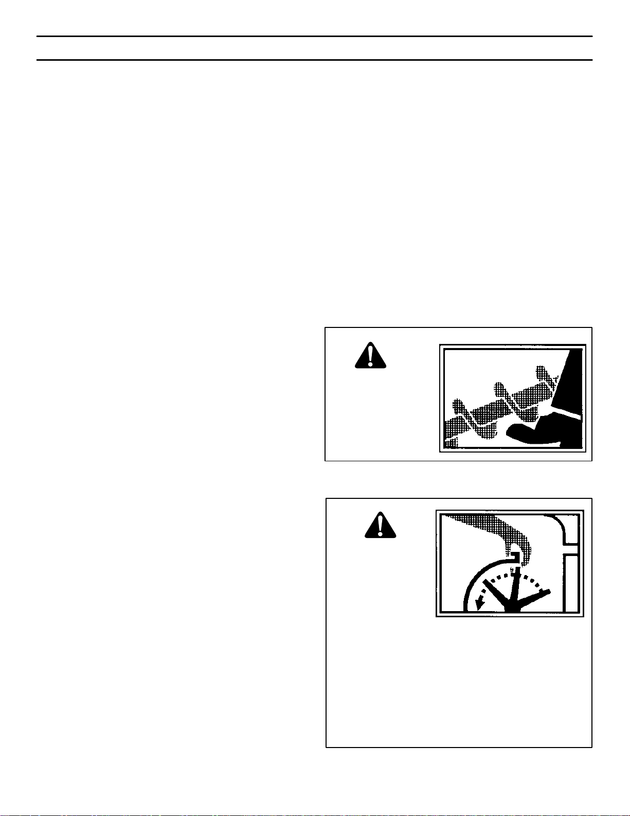
WARNING: Avoid
injury from rotating
auger- keep hands,
feet, and clothing
away.
WARNING: Do not
use hands to unclog discharge
chute.
• Stop engine/motor before removing debris.
• Do not walk in front of running machine.
• Do not discharge at bystanders.
• Keep people and pets a safe distance from the
machine.
• Before leaving machine, shut off engine/ motor
and remove key.
4
Page 5

TABLE OF CONTENTS
SAFETY DECALS 6. . . . . . . . . . . . . . . . . . . . . . . . . . . . . . . . . . . . . . . . . . . . . . .
WARRANTY 7. . . . . . . . . . . . . . . . . . . . . . . . . . . . . . . . . . . . . . . . . . . . . . . . . . . .
OWNER’S INFORMATION 7. . . . . . . . . . . . . . . . . . . . . . . . . . . . . . . . . . . . . . .
ASSEMBLY 7. . . . . . . . . . . . . . . . . . . . . . . . . . . . . . . . . . . . . . . . . . . . . . . . . . . .
PARTS BAGS CONTENTS: 8. . . . . . . . . . . . . . . . . . . . . . . . . . . . . . . . . . . .
TOOLS REQUIRED FOR ASSEMBLY 8. . . . . . . . . . . . . . . . . . . . . . . . . . .
HOW TO REMOVE THE SNOW THROWER FROM THE CARTON 8.
HOW TO INSTALL THE CHUTE CRANK 8. . . . . . . . . . . . . . . . . . . . . . . . .
HOW TO ASSEMBLE THE HANDLE 9. . . . . . . . . . . . . . . . . . . . . . . . . . . .
HOW TO INSTALL THE CHUTE 9. . . . . . . . . . . . . . . . . . . . . . . . . . . . . . . .
OPERATION 11. . . . . . . . . . . . . . . . . . . . . . . . . . . . . . . . . . . . . . . . . . . . . . . . . . . .
ENGINE AND SNOW THROWER OPERATING CONTROLS 11. . . . . . .
SNOWTHROWER OPERATION 12. . . . . . . . . . . . . . . . . . . . . . . . . . . . . . . .
HOW TO STOP THE SNOWTHROWER 12. . . . . . . . . . . . . . . . . . . . . . . . .
HOW TO CONTROL SNOW DISCHARGE 12. . . . . . . . . . . . . . . . . . . . . . .
HOW TO THROW SNOW 12. . . . . . . . . . . . . . . . . . . . . . . . . . . . . . . . . . . . . .
HOW TO MOVE FORWARD 12. . . . . . . . . . . . . . . . . . . . . . . . . . . . . . . . . . . .
HOW TO MIX THE FUEL MIXTURE 13. . . . . . . . . . . . . . . . . . . . . . . . . . . . .
BEFORE STARTING THE ENGINE 14. . . . . . . . . . . . . . . . . . . . . . . . . . . . . .
HOW TO STOP THE ENGINE 14. . . . . . . . . . . . . . . . . . . . . . . . . . . . . . . . . .
HOW TO START THE ENGINE 14. . . . . . . . . . . . . . . . . . . . . . . . . . . . . . . . .
HOW TO REMOVE SNOW FROM THE AUGER HOUSING 15. . . . . . . .
SNOW THROWING TIPS 15. . . . . . . . . . . . . . . . . . . . . . . . . . . . . . . . . . . . . .
SERVICE RECOMMENDATIONS 16. . . . . . . . . . . . . . . . . . . . . . . . . . . . . . . . .
MTF-031039C
LUBRICATION 16. . . . . . . . . . . . . . . . . . . . . . . . . . . . . . . . . . . . . . . . . . . . . . . .
HOW TO LUBRICATE THE IDLER ARM 17. . . . . . . . . . . . . . . . . . . . . . . . .
MAINTENANCE 18. . . . . . . . . . . . . . . . . . . . . . . . . . . . . . . . . . . . . . . . . . . . . . . . .
HOW TO ADJUST THE BELT TENSION 18. . . . . . . . . . . . . . . . . . . . . . . . .
HOW TO REPLACE THE AUGER BELT 18. . . . . . . . . . . . . . . . . . . . . . . . .
HOW TO FREE THE AUGER CABLE 19. . . . . . . . . . . . . . . . . . . . . . . . . . . .
HOW TO ADJUST THE CHUTE CRANK 20. . . . . . . . . . . . . . . . . . . . . . . . .
HOW TO ADJUST THE AUGER CONTROL CABLE 20. . . . . . . . . . . . . . .
HOW TO REPLACE THE DRIVE BELT 21. . . . . . . . . . . . . . . . . . . . . . . . . .
HOW TO REPLACE THE AUGER 22. . . . . . . . . . . . . . . . . . . . . . . . . . . . . . .
TO ADJUST THE CARBURETOR 23. . . . . . . . . . . . . . . . . . . . . . . . . . . . . . .
TO ADJUST OR REPLACE THE SPARK PLUG 23. . . . . . . . . . . . . . . . . . .
STORAGE 24. . . . . . . . . . . . . . . . . . . . . . . . . . . . . . . . . . . . . . . . . . . . . . . . . . . . . .
TROUBLE SHOOTING CHART 25. . . . . . . . . . . . . . . . . . . . . . . . . . . . . . . . . . .
REPLACEMENT PARTS 27. . . . . . . . . . . . . . . . . . . . . . . . . . . . . . . . . . . . . . . . .
PARTS SCHEMATICS 28. . . . . . . . . . . . . . . . . . . . . . . . . . . . . . . . . . . . . . . . . . .
SPECIFICATIONS 44. . . . . . . . . . . . . . . . . . . . . . . . . . . . . . . . . . . . . . . . . . . . . . .
5
Page 6
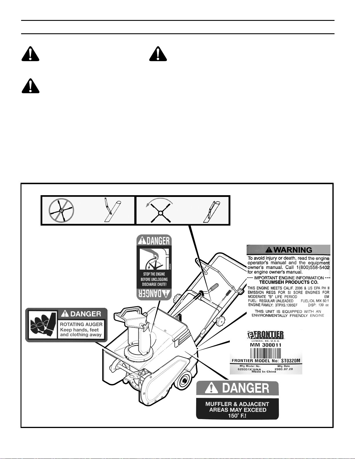
SAFETY DECALS
WARNING: If safety decals are damaged or missing, replace immediately.
Look for this symbol to indicate important safety precautions. This symbol indicates: “Attention! Become Alert! Your Safety Is At Risk.”
Before operation of your snowthrower, read the safety decals as shown on your snowthrower. The cautions and
warnings are for your safety. To avoid a personal injury or
damage to your snowthrower, understand and follow all
safety decals. If you have any questions regarding the
meaning or how to comply with the instructions, do not operate until you understand the purpose for the warning or
danger given in the safety decal. If you do not understand
the meaning, then thoroughly read all safety and operation
instructions in this Owner’s Manual or contact your local
dealer.
If any safety decals become worn or damaged and cannot
be read, order replacement decals from your local dealer.
Identifying Your Snowthrower
The snowthrower has two (2) identifying numbers: (1) unit
model number: (2) unit serial number. The two preceding
numbers are required to insure that the proper replacement parts are obtained when required. If you have any
questions concerning parts, service, or technical data, contact the dealer where the unit was purchased.
For complete warranty information refer to the warranty in
the Owner’s Information section of this manual.
MTF-031039C
Figure 1
6
Page 7

OWNER’S INFORMATION
THREE YEAR LIMITED WARRANTY
Murray warrants to the original purchaser of this Frontier Branded Snowthrower that this unit shall be free from defects in
material and workmanship under normal use and service for a period of Three (3) Year from the date of purchase; however,
this warranty does not cover accessories (such as electric starters) and Normal Wear Parts (except as noted below) as the
companies that manufacture these items furnish their own warranties and provide service through their authorized field
service facilities. For additional information, see the warranties covering these particular parts. If you are uncertain whether
your unit contains or is equipped with one or more of these parts, consult your dealer prior to purchase. Subject to the terms
and conditions noted in this Limited Warranty, we shall, at our option, repair or replace at no cost to the original purchaser
any part covered by this Limited Warranty during the applicable warranty period.
Normal Wear Parts are defined as drive belts, augers, shear pins, tires and headlights. These parts are warranted to be free
from defects in material and workmanship as delivered with the product. Any claim for repair or replacement of Normal Wear
Parts must be made within thirty (30) days of the date of purchase. No claims involving damage caused from material use,
abuse or misuse will be honored.
This Murray Three (3) Year Limited Warranty for your Frontier Branded Snowthrower is your exclusive remedy; however,
this warranty is void or does not apply to any unit that has been tampered with, altered, misused, abused. If used for
commercial and/or professional (non-homeowner) uses, the duration of this warranty is ninety (90) days after the date of
purchase. Your warranty does not cover minor mechanical adjustments which are not due to any defect in material or
workmanship. For assistance in making such adjustments, consult your Operator’s Manual.
The engine on this Frontier Branded Snowthrower is warranted to the original purchaser for only a Two (2) Year Limited
Warranty. See your engine manual for information regarding the warranty policy and items covered under warranty. See
your authorized John Deere/Frontier Dealer for service or replacement parts.
To make a claim under this Murray Three (3) Year Limited Warranty for your Frontier Branded Snowthrower, return the unit
(or if authorized in advance, the defective part) along with your proof of purchase to an Authorized John Deere/Frontier Dealer
near you. To locate the nearest Authorized John Deere/Frontier Dealer, check the Yellow Page listings in your local telephone
directory. If you return the entire unit, John Deere/Frontier will repair all warranty items. If authorize to return the defective
part only, John Deere/Frontier will either replace or repair the part. This Murray Three (3) Year Limited Warranty for your
Frontier Branded Snowthrower gives you specific legal rights, and you may also have other rights which vary from state to
state.
This Limited Warranty is given in lieu of all other expressed and implied warranties including the implied
warranty of merchantability and warranty of fitness for a particular purpose. If you need additional information on this
written warranty or assistance in obtaining service, contact you local John Deere/Frontier Dealer.
MT
FOR YOUR RECORDS
DATE PURCHASED:
MODEL NO:
SERIAL NO:
MTF-031039C
STORE WHERE PURCHASED:
ADDRESS:
CITY: STATE:
TELEPHONE :
Record this information about your unit so that you will
be able to provide it in case of loss or theft.
7
Page 8
ASSEMBLY
PARTS BAGS CONTENTS:
1 - 2.6 ounces 2-cycle oil
1 - Owner’s Manual
TOOLS REQUIRED FOR ASSEMBLY
1-Knife
1-Pliers
2-Adjustable Wrenches
HOW TO REMOVE THE SNOW THROWER
FROM THE CARTON
1. Locate all parts that are packed separately and remove
from the carton.
2. Remove and discard the packing material from around
the snow thrower.
WARNING: Always wear safety glasses or eye
shields while assembling the snowthrower.
Figure 6 shows the snow thrower in the operating position.
References to the right or left hand side of the snow thrower are from the viewpoint of the operator’s position behind
the unit.
3. Cut down all four corners of the carton and lay the side
panels flat.
4. Cut off the plastic bag that covers the snowthrower.
5. Hold onto the lower handle and pull the snow thrower off
the carton.
CAUTION: DO NOT back over cables.
6. Remove the packing material from the handle assembly.
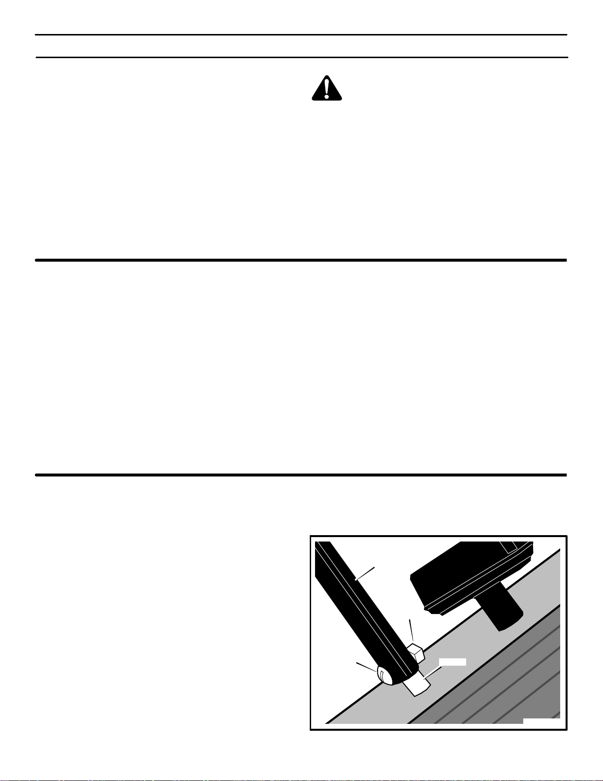
HOW TO INSTALL THE CHUTE CRANK
1. Remove the screw and nut from the shaft (see
Figure 2).
2. Put the chute crank rod through the bracket on the lower handlebar.
3. Install the chute crank rod onto the shaft.
4. Fasten the chute crank rod with the screw and nut that
were removed in step 1.
5. Raise the upper handle to the operating position. Hold
the upper handle apart to prevent scratching the lower
handle.
6. Line up the holes.Tighten the knobs.
MTF-031039C
Chute Crank
Rod
Nut
Screw
8
Shaft
Figure 2
Page 9
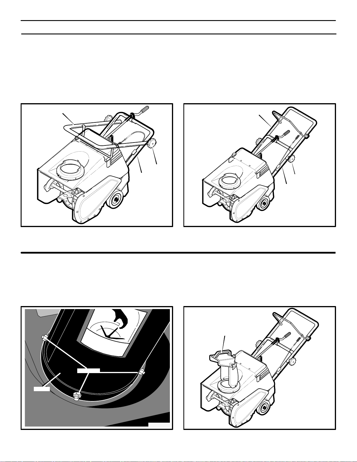
HOW TO ASSEMBLE THE HANDLE
ASSEMBLY
1. Remove the packing material from the upper and
lower handles.
2. Loosen the knobs on each side of the handle. (See
Figure 3)
3. Raise the upper handle to the operating position (see
Figure 4). Hold the upper handle apart to prevent
scratching the lower handle.
Upper Handle
Knob
Lower Handle
Figure 3
NOTE: Make sure the cables are not caught between
the upper and lower handle.
4. Tighten the knobs.
Upper Handle
Knob
Lower Handle
Figure 4
HOW TO INSTALL THE CHUTE
1. Remove the three bolts and lock nuts from the chute
base (see Figure 5).
Locknuts
Chute
Figure 5
MTF-031039C
2. Install the chute with the bolts and locknuts. Make
sure the locknuts are to the outside as shown.
Chute
Figure 6
9
Page 10

ASSEMBLY
n
CHECKLIST
Before you operate your new snowthrower, to ensure that
you receive the best performance and satisfaction from
this quality product, please review the following checklist:
n All assembly instructions have been completed.
n The discharge chute rotates freely.
n No remaining loose parts in carton.
While learning how to use your snow thrower, pay extra
attention to the following important items:
n Make sure the fuel tank is filled with the correct mixture
(50:1 ratio) of gasoline and oil.
n Become familiar with the location of all controls and un-
derstand their function.
n Before starting the engine, make sure all controls oper-
ate correctly.
MTF-031039C
10
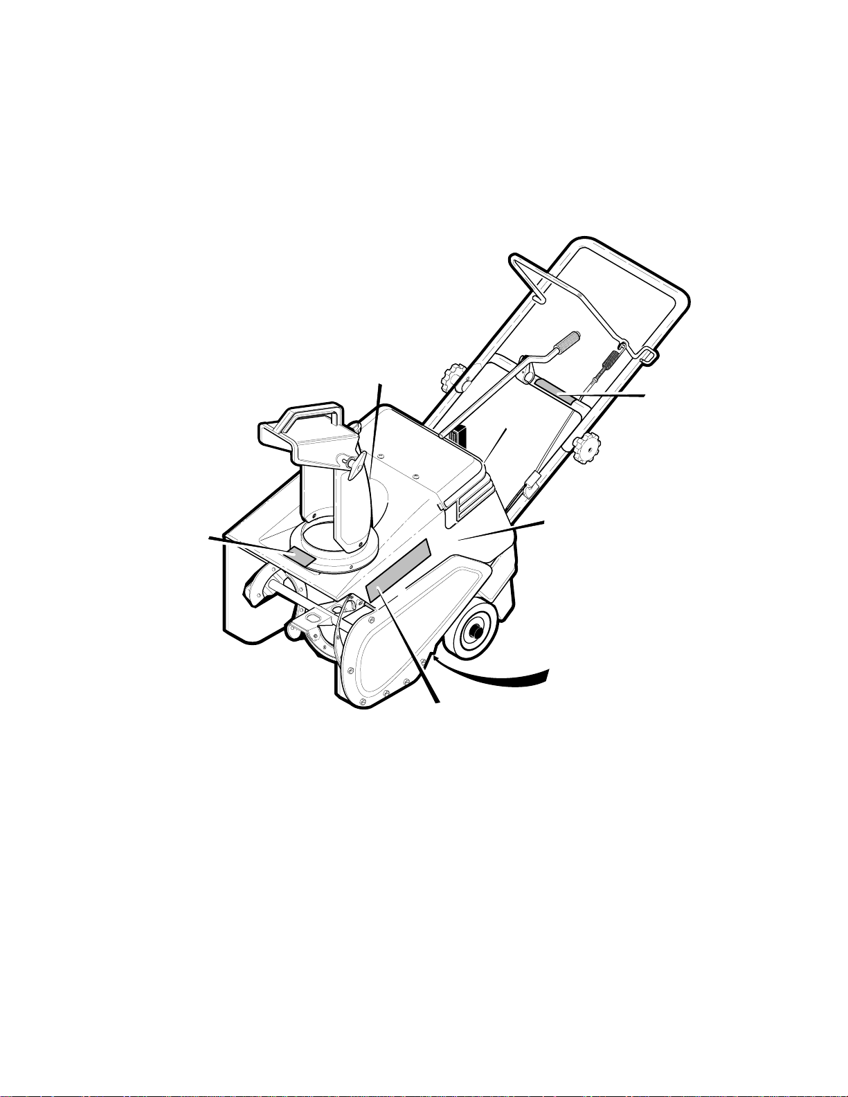
Page 11
OPERATION
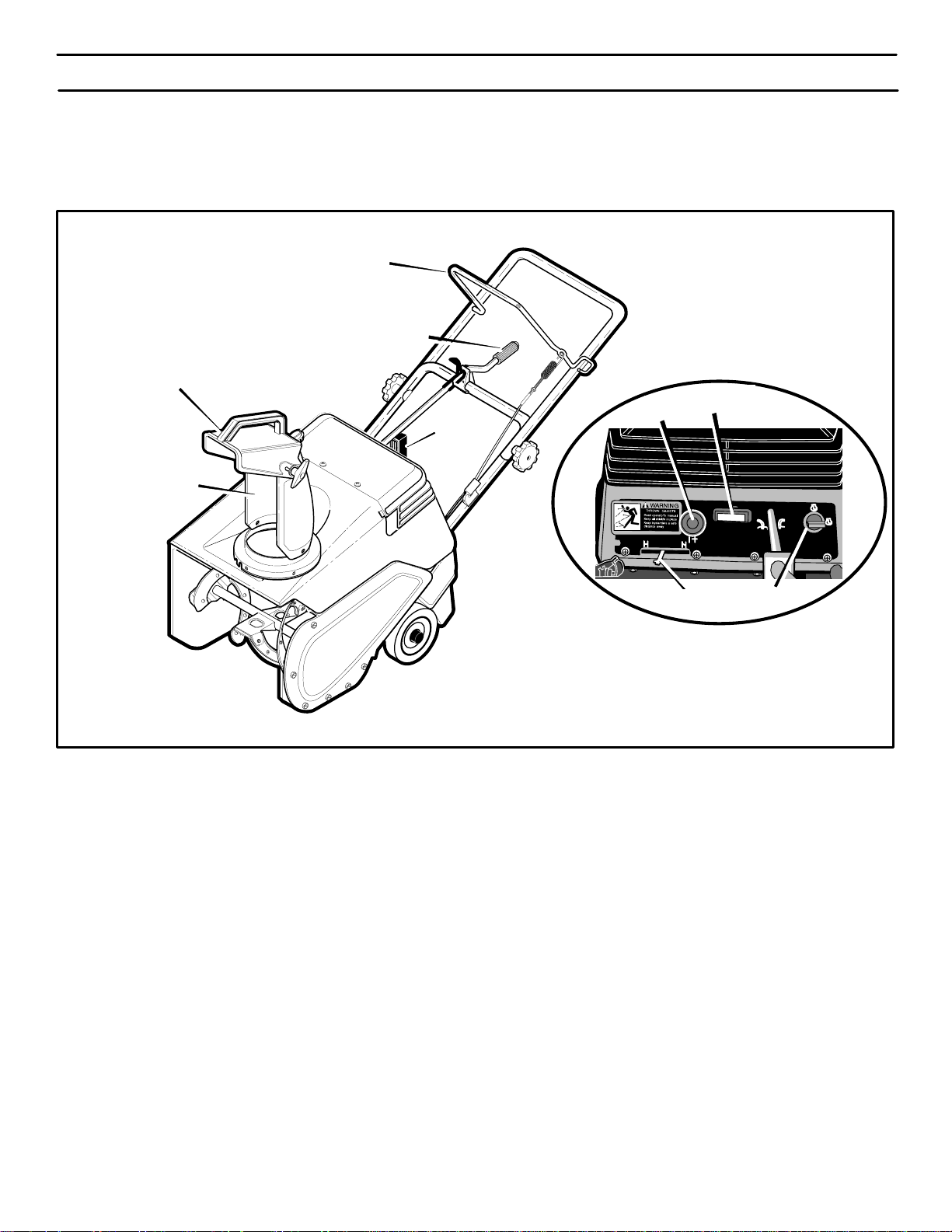
KNOW YOUR SNOWTHROWER
READ THIS OWNER’S MANUAL AND SAFETY RULES BEFORE OPERATING YOUR SNOWTHROWER. Compare the
illustrations with your SNOWTHROWER to familiarize yourself with the location of various controls and adjustments. Save
this manual for future reference.
Auger Drive Lever
Chute Control Rod
Chute Deflector
Recoil
Starter
Handle
Discharge Chute
ENGINE AND SNOW THROWER OPERATING CONTROLS
The engine operating controls and their functions are as
follows:
Auger Drive Lever - Starts and stops the auger.
Chute Control Rod - Changes the direction of snow throw-
ing through the discharge chute.
Chute Deflector - Changes the distance the snow is
thrown.
Primer
Button
Choke Control
Recoil
Starter
Ignition Switch
Key
Figure 7
Ignition Switch Key - Must be inserted and turned to the
ON position to start the engine.
Recoil Starter Handle - Starts the engine manually.
Electric Starter Button - (Not shown) On electric start mod-
els, use to start the engine when using the 120V electric
starter.
Choke Control - Used to start a cold engine.
Discharge Chute - Changes the direction the snow is
thrown.
MTF-031039C
Primer Button - Injects fuel directly into the carburetor
manifold for fast starts in cold weather.
11
Page 12

OPERATION
SNOWTHROWER OPERATION
The most effective use of the snowthrower will be established
by experience, taking into consideration the terrain, wind
conditions and building location which will determine the
direction of the discharge chute.
NOTE: Do not discharge snow toward a building as
hidden objects could be thrown with sufficient force to
cause damage.
WARNING: Read Owner’s Manual before operating machine. This machine can be dangerous
if used carelessly.
Never operate the snowthrower without all guards,
covers, and shields in place.
Never direct discharge toward windows or allow bystanders near machine while engine is running.
Stop the engine whenever leaving the operating position.
Disconnect spark plug before unclogging the impeller
housing or the discharge chute and before making repairs or adjustments.
When leaving the machine, remove the ignition key.
To reduce the risk of fire, keep the machine clean and
free from spilled gas, oil and debris.
NOTE: If the snowthrower continues to slowly move
forward, see “How To Adjust The Auger Control
Cable” in the Maintenance Section.
8. To stop the engine, move the ignition key to the OFF
position.
HOW TO CONTROL SNOW DISCHARGE
1. Turn the chute control rod to set the direction of the
snow throwing. (See Figure 7)
2. Loosen the wing knob on the chute deflector and move
the deflector to set the distance. Move the deflector (Up)
for more distance, (Down) for less distance. Then tighten
the wing knob (See Figure 8).
Deflector Down
Deflector Up
HOW TO STOP THE SNOWTHROWER
7. To stop throwing snow, release the auger drive lever.
(See Figure 9).
HOW TO THROW SNOW
1. Engage the auger drive lever. (See Figure 9).
2. To stop throwing snow, release the auger drive lever.
HOW TO MOVE FORWARD
1. Hold the auger drive lever against the handle (See
Figure 9). The auger will begin rotating.
2. To go forward, raise the handle to allow the rubber au-
ger blades to contact the ground. Maintain a firm hold on
the handle as the snowthrower starts to move forward.
Guide the snowthrower by moving the handle either left
or right. Do not attempt to push the snowthrower.
3. To stop, release the auger drive lever.
Wing Knob
Figure 8
NOTE: If the auger continues to rotate, see “How To
Adjust The Auger Control Cable” in the Maintenance
section.
Auger
Drive Lever
“Z” Hook
Figure 9
MTF-031039C
12
Page 13
OPERATION
BEFORE STARTING THE ENGINE
WARNING: Experiences indicates that alcohol
blended fuels (called gasohol or those using
ethanol or methanol) can attract moisture
which leads to separation and formation of acids during storage. Acidic gas can damage the fuel system
of an engine while in storage.
NOTE: To avoid engine problems, the fuel system
must be emptied before storage for 30 days or longer.
Start the engine and let it run until the fuel lines and
carburetor are empty. Use the carburetor bowl drain
to empty residual gasoline from the float chamber.
Use fresh fuel next season. See the Storage section in
this manual for additional information.
Never use engine or carburetor cleaner products in the
fuel tank or permanent damage can occur.
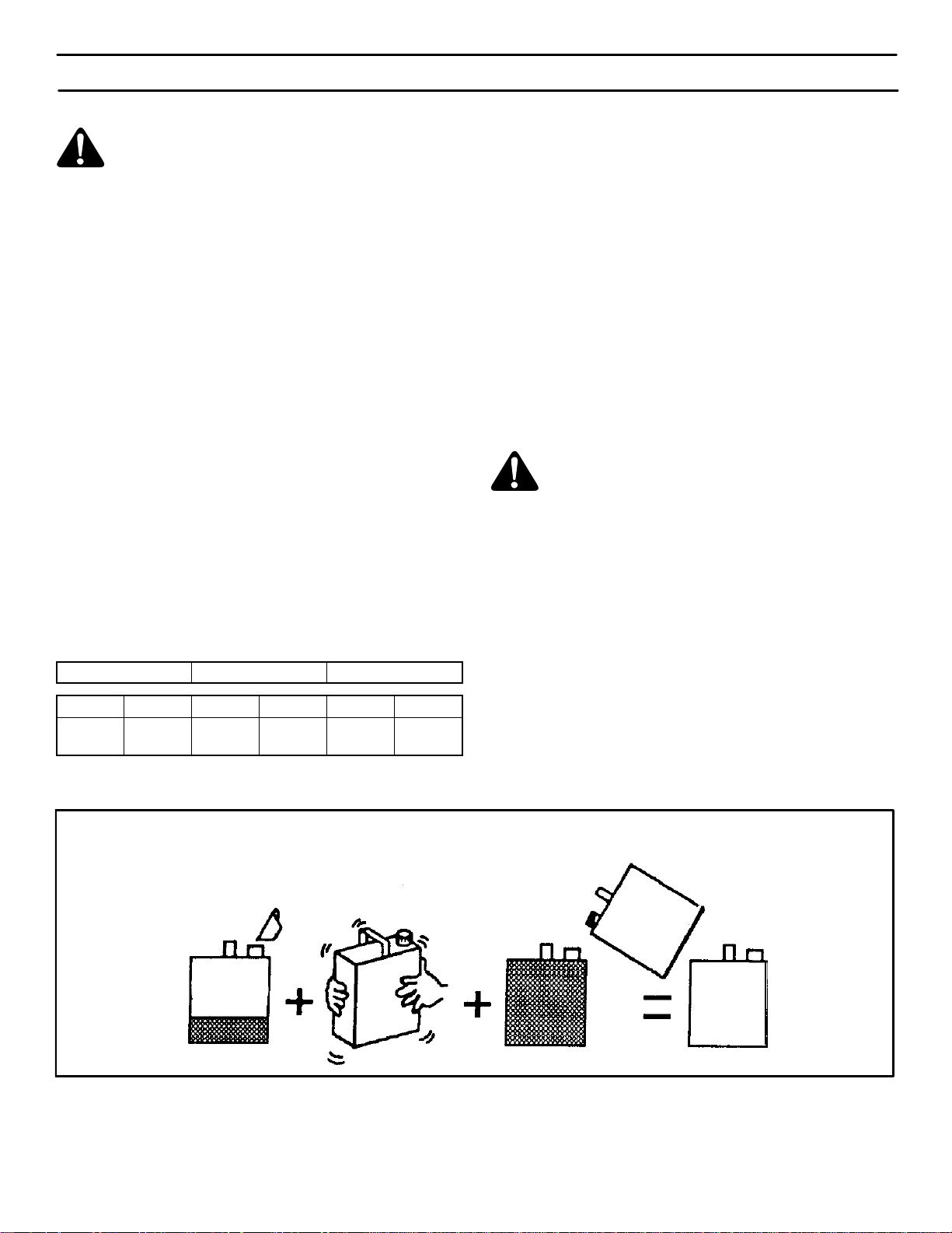
HOW TO MIX THE FUEL MIXTURE
The two cycle engine, used on this snow thrower, requires
a mixture of gasoline and oil for lubrication of the bearings
and other moving parts. The correct fuel mixture ratio is
50:1 (2.6 oz. oil per one gallon of gas - see the Fuel Mixture Chart). Gasoline and oil must be pre-mixed in a clean
gasoline container. Always use fresh, clean, unleaded gasoline.
FUEL MIXTURE CHART (mixture 50:1)
U.S. IMPERIAL SI. (Metric)
GAS OIL GAS OIL GAS OIL
1 Gal. 2.6
oz.
1 Gal. 3.1 oz. 4
liter
80
ML
Mix gasoline and oil as follows:
1. Pour one (1) U.S. quart of fresh, clean, unleaded automotive gasoline into a one gallon size gasoline container.
2. Add 2.6 ounces of clean, high quality, two-cycle oil to
the gasoline container.
IMPORTANT: Do not use outboard motor oil or
multi-viscosity oils,such as 10W-30 or 10W-40.
3. Install the fuel cap onto the gasoline container. Vigorously shake the gasoline container to mix the oil with
the gasoline.
4. Add an additional three (3) U.S. quarts of gasoline to
the gallon container. Again shake the gasoline container.
WARNING: Gasoline is flammable. Always use
caution when handling or storing gasoline.
Do not fill fuel tank while snow thrower is running, when it is hot, or when snow thrower is in an
enclosed area.
Keep away from open flame or an electrical spark and
do not smoke while filling the fuel tank.
Never fill the tank completely. Fill the tank to within
1/4”-1/2” from the top to provide space for expansion
of fuel.
Always fill fuel tank outdoors and use a funnel or
spout to prevent spilling.
Make sure to wipe up any spilled fuel before stating
the engine.
Store gasoline in a clean, approved container and
keep the cap in place on the container.
MTF-031039C
Do not fill the fuel tank with gasoline that does not have oil mixed in it. Shake the gasoline container before
each filling of the fuel tank.
OIl
(2.6 oz.)
Gasoline
1U.S.
Quart
1 U.S. Gallon container
Shake Can
Add more gas
(3 U. S. Quarts)
13
1 U.S.
Gallon
Special
Gasoline
Figure 10
Page 14

OPERATION
BEFORE STARTING THE ENGINE
1. Before you service or start the engine, familiarize yourself with the snow thrower. Be sure you understand the
function and location of all controls.
2. Be sure that all fasteners are tight.
HOW TO START THE ENGINE
The following starting instructions include directions for both
Recoil Start and Electric Start engines. For models that are
Recoil Start only, disregard the Electric Start information.
Electric Start models are equipped with a 120 volt AC electric starter and also a recoil starter. Before starting the engine, make certain that you have read the following
information.
The starter i s d esigned t o o perate o n 120 volt A .C.
household current. Carefully follow all instruc-
tions in the “How To Start The Engine” section.
To connect a 120 volt A.C. power c ord, always c onnect
the power cord to the switch box on the engine first.
Then, plug t he o ther e nd into the r eceptacle. When disconnecting the p ower c ord, a lways u nplug t he e nd f rom
the receptacle first.
3. Before starting the engine, make sure all controls operate correctly.
HOW TO STOP THE ENGINE
To stop the engine, move the ignition key to the stop position.
S Push four times if temperature is below 15° F (-10° C).
S Push five time if temperature is below 0° F (-18° C).
9. (Electric Start) Push on the electric start button until
the engine starts. Do not crank for more than 10 seconds
at a time. The electric starter is thermally protected. If the
electric starter overheates, it will automatically stop and
can only be restarted when it has cooled to a safe temperature. A wait of about 5 to 10 minutes is required to
allow the electric starter to cool.
10. (Recoil Start) Rapidly pull the recoil starter handle. Do
not allow the recoil starter handle to snap back. Slowly
return the recoil starter handle.
11. If the engine does not start in 5 or 6 tries, See the “Trouble
Shooting Chart” Instructions.
12. (Electric Start) When the engine starts, release the
electric start button.
HOW TO START A COLD ENGINE
1. Fill the fuel tank with a fresh, clean fuel mixture. See
“How To Mix The Fuel Mixture”.
2. Move the choke control to FULL position.
3. Make sure the auger drive lever is in the disengaged
(released) position.
4. Insert the ignition key and turn to the ON position.
5. Move the choke control to the full choke position.
6. (Electric Start) Connect the power cord to the switch
box located on the engine.
7. (Electric Start) Plug the other end of the power cord into
a 120 VOL T, A.C. receptacle. (See the WARNING in this
section).
8. Push the primer button while covering the vent hole as
follows: Remove finger from primer button between
primes.
S Do not prime if temperature above 50° F (10° C).
S Push twice if temperature is 50° F (10° C) to
15°F (-10° C).
MTF-031039C
13. (Electric Start) First disconnect the power cord from the
receptacle. Then, disconnect the power cord from the
switch box.
14. As the engine warms up, move the choke control to 1/2
choke position. When the engine runs smoothly, move
the choke control to the off position.
NOTE: Allow t h e e ngine to warm up for several minutes
before blowing snow in temperatures below 05F.
WARM START
If restarting a warm engine after a short shutdown, leave
choke at “OFF” and do not push the primer button. If the en-
gine fails to start, follow the Cold Start instructions.
WARNING: Never run engine indoors or in enclosed, poorly ventilated areas. Engine exhaust
contains CARBON MONOXIDE, AN ODORLESS
AND DEADLY GAS. Keep hands, feet, hair and loose
clothing away from any moving parts on engine and
snow thrower.
The temperature of muffler and nearby areas may exceed 1505F. Avoid these areas.
DO NOT allow children or young teenagers to operate
or be near snow thrower while it is operating.
14
Page 15

OPERATION
HOW TO REMOVE SNOW FROM THE AUGER
HOUSING
WARNING: Do not attempt to remove snow or
debris that may become lodged in auger
housing without taking the following precau-
tions.
SNOW THROWING TIPS
1. When the handle is raised, the auger blades will engage
the ground and the snow thrower will move forward.
When the auger drive lever is released, the auger blades
will stop. If the blades do not stop, see “How To Adjust
The Auger Control Cable” in the Service And Adjustment
section.
2. Most efficient snow throwing is accomplished when the
snow is removed immediately after if falls.
3. For complete snow removal, slightly overlap each previous path.
4. Whenever possible, discharge the snow down wind.
5. The distance the snow will be discharged can be adjusted by moving the discharge chute deflector. Raise
the deflector for more distance or lower the deflector for
less distance.
6. In windy conditions, lower the chute deflector to direct the
discharged snow close to the ground where it is less likely to blow into unwanted areas.
7. For safety and to prevent damage to the snow thrower,
keep the area to be cleared free of stones, toys and other
foreign objects.
8. Do not use the auger propelling feature when clearing
gravel or crushed rock driveways. Move the handle down
to slightly raise the auger.
9. The forward speed of the snow thrower is dependent on
the depth and weight of the snow. Experience will establish the most effective method of using the snow thrower
under different conditions.
1. Release the auger drive lever.
2. Remove the ignition key.
3. Disconnect the spark plug wire.
4. Do not place your hands in the auger housing or the dis-
charge chute. Use a pry bar to remove any snow or debris.
10. After each snow throwing job, allow the engine to run for
a few minutes. The snow and accumulated ice will melt
off the engine.
11. Clean the snow thrower after each use.
12. Remove ice, snow and debris from the entire snow
thrower. Flush with water to remove all salt or other
chemicals. Wipe snow thrower dry.
DRY AND AVERAGE SNOW
1. Snow up to eight inches deep can be removed rapidly
and easily by walking at a moderate rate. For snow or
drifts of a greater depth,slow your pace to allow the discharge chute to dispose of the snow as rapidly as the auger receives the snow.
2. Plan to have the snow discharged in the direction the
wind is blowing.
WET PACKED SNOW
Move slowly into wet, packed snow. If the wet, packed snow
causes the auger to slow down or the discharge chute begins
to clog, back off and begin a series of short back and forth
jabs into the snow . These short back and forth jabs, four to six
inches, will “belch” the snow from the chute.
SNOW BANKS AND DRIFTS
In snow of greater depth than the unit, use the same “jabbing”
technique described above. Turn the discharge chute away
from the snow bank. More time will be required to remove
snow of this type than level snow.
MTF-031039C
15
Page 16

SERVICE RECOMMENDATIONS
N
H
SERVICE RECOMMENDATIONS
PROCEDURE
S
Tighten all screws and nuts
O
Lubricate Chute Control
Flange
W
FIRST
2
HOUR
√ √
√ √
BEFORE
EACH
USE
OFTEN
EVERY
5
HOURS
EVERY
10
HOURS
EVERY
25
HOURS
BEGINNING
EACH
SEASON
√
BEFORE
STORAGE
T
Lubricate Auger Bail
H
R
Check Auger Drive Cable
O
Adjustment
(See Cable Adjustment)
W-
√ √
√
E
Check Drive Belt
R
The warranty on this snowthrower does not cover items that have been subjected to operator abuse or negligence. To receive
full value from the warranty , operator must maintain snowthrower as instructed in this manual. The following Service Recom-
mendations are supplied to assist operator to properly maintain snow thrower. This is a check list only. Adjustment referred
to will be found in Adjustments/Repairs section of this manual.
√
AFTER EACH USE
1. Check for any loose or damaged parts.
2. Tighten any loose fasteners.
3. Check and maintain the auger.
4. After each use, remove all snow and slush off of the
snowthrower to prevent freezing of auger or controls.
5. Check controls to make sure they are functioning
properly.
6. If any parts are worn or damaged, replace immediately.
LUBRICATION
Before Storage
1. Lubricate the chute control flange. Apply a clinging
type of grease such as Lubriplate (see Figure 11).
2. Apply oil to the pivot point on each side of the auger
bail (see Figure 11).
3. Wipe off the excess oil.
Chute Control
Flange
Auger Bail
Pivot
Point
Figure 11
MTF-031039C
16
Page 17

SERVICE RECOMMENDATIONS
HOW TO LUBRICATE THE IDLER ARM
CAUTION: DO NOT get oil on the belt or pulleys.
1. Remove the screws from the belt cover . Remove the belt
cover.
2. Apply a drop of oil to the idler arm at point B (see
Figure 12).
3. Pivot the auger bail up and down several times.
4. Wipe off the excess oil.
5. Install the cover.
Idler Arm
B
Figure 12
MTF-031039C
17
Page 18

MAINTENANCE
HOW TO ADJUST THE BELT TENSION
IMPORTANT: When you release the auger bail, the auger must stop rotating. If the auger does not stop, adjust the belt tension as follows:
1. Disconnect the spark plug wire from the spark plug.
2. Remove the belt cover.
3. Loosen the idler pulley nut (see Figure 14).
4. Move the idler pulley to the bottom of the idler arm
slot. If the idler pulley is already in the bottom position, replace the auger belt. See How To Replace The
Auger Belt in the Maintenance section.
5. Tighten the idler pulley nut.
6. Install the belt cover.
HOW TO REPLACE THE AUGER BELT
1. Disconnect the spark plug wire from the spark plug.
2. Remove the belt cover.
3. Remove the belt guide (see Figure 14).
4. Remove the auger belt from the engine drive pulley.
5. Push down the idler arm to move the brake away the
auger drive pulley. Remove the auger belt from the
auger drive pulley.
6. Loosen the idler pulley nut. Move the idler pulley to the
top of the idler arm slot. Tighten the idler pulley nut.
7. Install a new auger belt.
8. Install the belt guide. Make sure the fasteners that
secure the belt guide are tight.
9. Check the operation. When you release the auger
bail, the auger must stop turning. When you engage
the auger bail, there MUST be clearance between the
brake arm and the auger drive pulley.
10. When you release the auger bail, the auger must stop
rotating. Make sure the brake contacts the auger
drive pulley (Figure 14) and that the auger cable
spring (Figure 13) has slack (no tension). If not, check
the cable spring adjustment as follows:
11. Remove the boot from the auger cable spring as follows:
S Disconnect the end of the idler spring from the
idler arm (see Figure 14).
S Remove the auger belt from the idler pulley.
S Remove the end of the auger cable spring from
the auger bail (see Figure 13).
S Remove the boot from the auger cable spring.
S Attach the end of the auger cable spring to the
auger bail.
12. To adjust the auger cable spring:
S Install the auger belt to the idler pulley (see
Figure 14).
S Attach the idler spring to the idler arm.
S Loosen the jam nut (see Figure 13).
S Turn the adjuster until the auger cable is slightly
slack.
S Tighten the jam nut.
13. Remove the idler spring from the idler arm (see
Figure 14). Remove the auger belt from the idler
pulley. Install the boot to the auger cable spring.
14. Install the auger belt, idler spring, and belt cover.
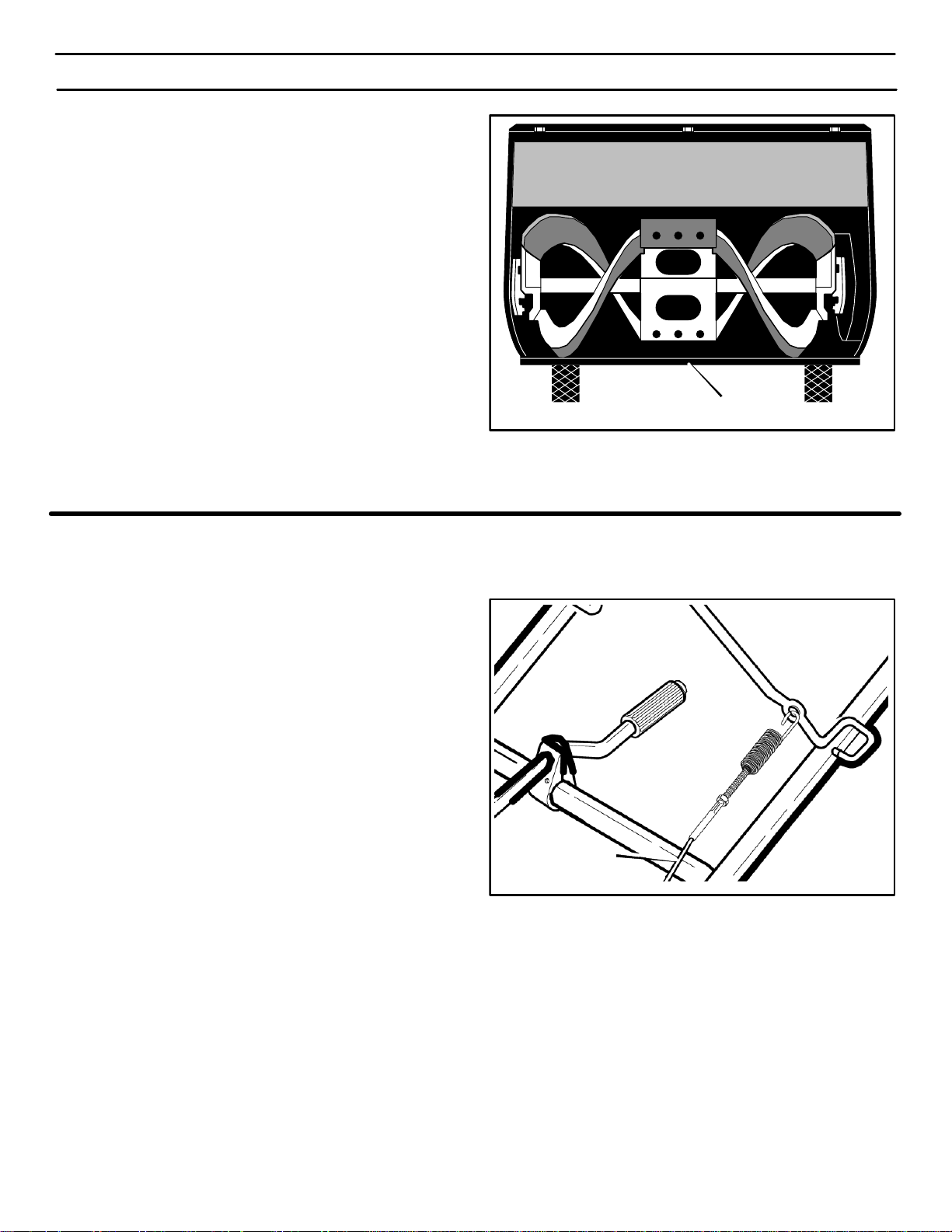
Auger Cable Spring
Jam Nut
Adjuster
Auger Cable
Auger
Bail
Figure 13
MTF-031039C
Auger
Drive
Pulley
Brake
Idler Arm
Auger
Belt
Idler
Spring
18
Idler Pulley
Belt Guide
Idler Pulley
Nut
Engine Drive
Pulley
Figure 14
Page 19
MAINTENANCE
HOW TO REPLACE THE SCRAPER BLADE
1. Remove the fasteners that secure the scraper blade
(Figure 15).
2. Install a new scraper blade and secure with the
fasteners removed in step 1.
HOW TO FREE THE AUGER CABLE
IMPORTANT: If the auger cable will not move when you
ENGAGE the bail, the auger cable could be frozen inside the conduit. DO NOT pull on the auger cable.
Instead, thaw the conduit and lubricate the auger
cable.
1. Thaw the conduit so the auger cable moves freely.
2. Work grease into the opening on the top of the conduit
where the auger cable enters.
Scraper Blade
Figure 15
MTF-031039C
Conduit
Figure 16
19
Page 20

WARNING: To prevent accidental starting when
making any adjustments or repairs, always disconnect the spark plug wire and place it where
it cannot make contact with the spark plug .
MAINTENANCE
HOW TO ADJUST THE CHUTE CRANK
If the chute crank will not rotate fully to the left or right, adjust
as follows.
1. Remove the top cover. See “How To Remove The Top
Cover”.
2. Loosen the nuts.
3. Move the crank adjusting bracket to allow 1/8 inch
(3mm) clearance between the notch in the flange and
the outer diameter of the worm gear.
4. Tighten the nuts.
HOW TO ADJUST THE AUGER CONTROL CABLE
The auger control cable is adjusted at the factory. During normal use, the auger control cable can become stretched and
the auger drive lever will not properly engage or disengage
the auger.
1. Remove the “Z” hook from the auger drive lever
(Figure 18).
Nut
Flange
1/8” (3mm)
Crank Adjusting
Bracket
Worm Gear
Figure 17
2. Slide the cable boot off the cable adjustment bracket
(Figure 19).
3. Push the bottom of the auger control cable through the
cable adjustment bracket until the “Z” hook can be removed.
4. Remove the “Z” hook from the cable adjustment brack-
et. Move the “Z” hook down to the next adjustment hole.
5. Pull the auger control cable up through the cable ad-
justment bracket.
6. Put the cable boot over the cable adjustment bracket.
7. Install the “Z” hook to the auger drive lever.
8. To check the adjustment, start the snow thrower. Make
sure the auger does not rotate when the auger drive lever
is released.
Auger Drive
Lever
Z-Hook
Cable Boot
Cable Adjustment
Bracket
Figure 18
Auger Control Cable
Z-Hook
Figure 19
MTF-031039C
20
Page 21

MAINTENANCE
HOW TO REPLACE THE DRIVE BELT
The drive belt is of special construction and must be replaced with original factory replacement belt available from
your nearest authorized service center.
1. Remove the belt cover. See “How To Remove The Belt
Cover”.
2. Remove the drive belt from the idler pulley. (See
Figure 20 and Figure 21)
3. Remove the drive belt from the engine pulley. Be
careful, not to bend the belt guides.
4. Remove the drive belt from the auger pulley. (See
Figure 21)
5. Remove the old drive belt.
Idler Pulley
Drive Belt
Idler Pulley
Belt Guide
Engine PUlley
Belt Guide
Figure 20
Engine
Pulley
6. To install the new drive belt, reverse the above steps.
7. Make sure the drive belt is seated properly on the pul-
leys.
NOTE: When the auger control lever is engaged, the
belt guides must be 1/16” from the drive belt . (See
Figure 22)
8. Install belt cover. See “How To Remove The Belt Cov-
er”.
Idler Pulley
Drive Belt
Drive Belt
Auger Pulley
Engine Pulley
Figure 21
MTF-031039C
21
1/16 inch
Belt Guide
Figure 22
Page 22
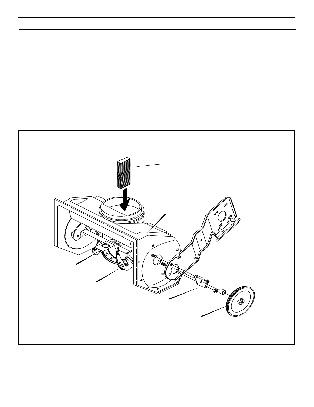
HOW TO REPLACE THE AUGER
MAINTENANCE
1. Remove the belt cover. See “How To Remove The Belt
Cover”.
2. Remove the drive belt. See “How To Replace The Drive
Belt”.
3. Remove the auger pulley from the auger shaft
(threads are left hand; turn clockwise to remove). (See
Figure 23).
4. To keep the auger from rotating, set a 2”x4” piece of
wood on the center paddle to secure auger.
5. Remove the fasteners from the bearing assembly. Re-
move the bearing assembly from the auger housing.
6. Slide the auger out of the bearing assembly on the
right side of the snow thrower.
7. Tip the auger enough to allow the auger to slide out of
the auger housing.
8. To install auger, reverse the above steps.
Wood
Center Paddle
Auger Housing
Auger
Bearing Assemlby
Auger Pulley
Figure 23
MTF-031039C
22
Page 23
MAINTENANCE
TO ADJUST THE CARBURETOR
The carburetor is not adjustable. Engine performance
should not be affected at altitudes up to 7,000 feet. For
operation at higher elevations, contact your nearest authorized service center.
IMPORTANT: Never tamper with the engine governor,
which is factory set for proper engine speed. Over-speeding the engine above the factory high speed setting can be
dangerous. If the engine-governed high speed needs an
adjustment, contact an authorized service center. They
have the proper equipment and experience to make any
necessary adjustments.
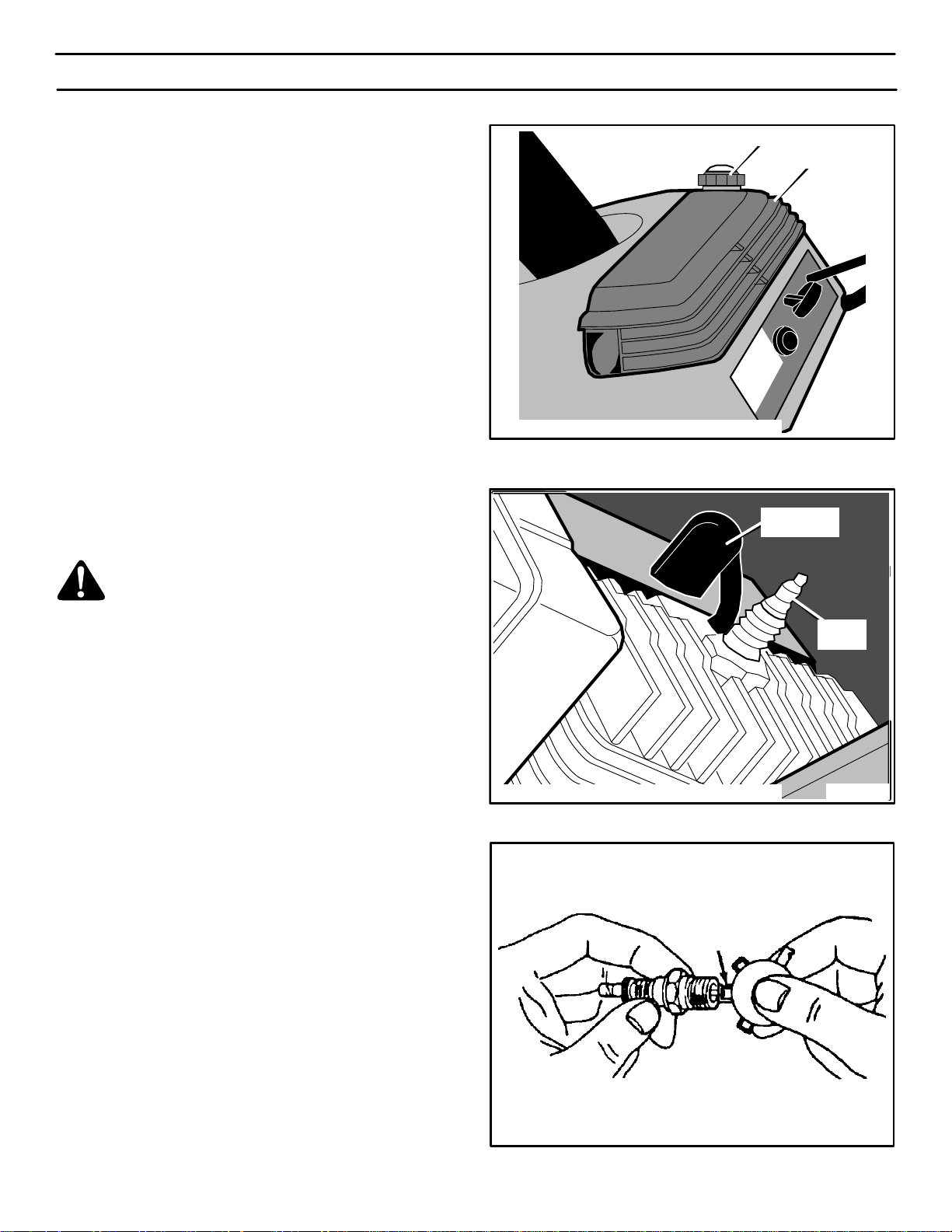
TO ADJUST OR REPLACE THE SPARK PLUG
Fuel Cap
Shroud
Check the spark plug every twenty-five (25) hours. Re-
place the spark plug if the electrodes are pitted or burned
or if the porcelain is cracked.
The spark plug is housed in the engine compartment under
the top cover and cannot be seen under normal conditions.
WARNING: STOP the engine. Wait for it to cool
before removal of spark plug.
CAUTION: DO NOT clean the plug with abrasives.
1. Remove the fuel cap (see Figure 24).
2. Remove the screws from the shroud. Remove the
shroud. Install the fuel cap.
3. Disconnect the spark plug wire (see Figure 25).
4. Clean the area around the spark plug base to prevent dirt
from entering the engine when the spark plug is removed.
5. Remove the spark plug.
Spark Plug
Wire
Figure 24
Spark
Plug
Figure 25
6. Check the spark plug. If the spark plug is cracked,
fouled or dirty, it must be replaced .
7. Set the gap between the electrodes of the new spark
plug at 0.030 inch (Figure 26).
8. Install the spark plug in the cylinder head and firmly tight-
en. Recommended torque is 18 to 20 foot pounds. Attach
the spark plug wire.
9. Remove the fuel cap and install the shroud (see
Figure 24).
10. Install the fuel cap.
MTF-031039C
.030” (0.76 mm) Gap
Figure 26
23
Page 24

STORAGE
OFF SEASON STORAGE
WARNING: Never store the engine, with fuel i n
the tank, indoors or in a poor ventilated enclo-
sure where fuel fumes could reach an open
flame, spark or pilot light as on a furnace, water heater ,
clothes dryer, etc.
Handle gasoline carefully. It is highly flammable and
careless use could result In serious fire damage to your
person and /or property.
Drain fuel into approved containers outdoors, away
from open flame.
If the snowthrower is to be stored for thirty (30) days or more
at the end of the snow season, the following steps are
recommended to prepare your snowthrower for storage.
NOTE: Gasoline must be removed or treated to prevent
gum deposits from forming in the tank, filter, hose, and
carburetor during storage.
1. To remove gasoline, run engine until tank is empty and
engine stops.
If you do not want to remove the gasoline, add fuel stabilizer
to any gasoline left in the tank to minimize gum deposits and
acids. If the tank is almost empty, mix stabilizer with fresh
gasoline in a separate container and add some to the tank.
ALWAYS FOLLOW INSTRUCTIONS ON STABILIZER
CONTAINER. THEN RUN ENGINE AT LEAST 10 MINUTES
AFTER STABILIZER IS ADDED TO ALLOW MIXTURE TO
REACH CARBURETOR. STORE SNOWTHROWER IN
SAFE PLACE.
2. Lubricating the piston/cylinder area. This can be done by
first removing the spark plug and squirting clean engine
oil into the spark plug hole. Then cover the spark plug
hole with a rag to absorb oil spray. Next, rotate the engine
by pulling the starter two or three times. Finally, reinstall
spark plug and attach spark plug wire.
3. Thoroughly clean the snowthrower.
4. Lubricate all lubrication points (see “Lubrication“ in the
Service Recommendations section).
5. Insure that all nuts, bolts, and screws are securely fastened. Inspect all visible moving parts for damage,
breakage, and wear. Replace if necessary.
6. Touch up all rusted or chipped paint surfaces; sand lightly
before painting.
7. Cover the bare metal parts of the blower housing and auger with rust preventative.
8. If possible, store your snowthrower indoors and cover it
to give protection from dust and dirt.
9. On models with folding handles, loosen the knobs that
secure the upper handle. Rotate the upper handle back.
10. If the machine must be stored outdoors, block up the snowthrower and insure the entire machine is off the
ground. Cover the snowthrower with a heavy tarpaulin.
REMOVING THE SNOWTHROWER FROM
STORAGE
When removing the snowthrower from storage, follow the
steps below.
1. Put the upper handle in the operating position, tighten the
knobs that secure the upper handle.
2. Fill the fuel tank with a fresh fuel-oil mixture. See “How
to Mix The Fuel Mixture” in the Operation section.
3. Lubricate the auger bail and idler arm.
4. Check the spark plug. Make sure the gap is correct. If the
spark plug is worn or damaged, replace before using.
5. Make sure all fasteners are tight.
6. Make sure all guards, shields, and covers are in place.
7. Make sure all adjustments are correct.
MTF-031039C
24
Page 25

TROUBLE SHOOTING CHART
PROBLEM LOOK FOR REMEDY
Difficult starting Defective spark plug. Replace defective spark plug.
Engine runs erratically Blocked fuel line. Clean fuel line.
Empty gas tank. Check fuel supply,
Stale gasoline. Add fresh gasoline.
Water or dirt in fuel system. Remove carburetor bowl to drain fuel tank. Refill
with fresh fuel. CAUTION: Do not remove
carburetor bowl when the engine is hot.
Engine stalls Unit running on CHOKE. Set choke lever to RUN position.
Loss of power Gas cap vent hole is plugged. Remove ice and snow from cap. Be sure vent
hole is clear.
Excessive vibration Loose parts. Stop engine immediately and remove spark plug
wire. Tighten all bolts and make all necessary
repairs. If vibration continues, have the unit
serviced by a competent repairman.
Unit fails to propel
itself
Unit fails to discharge
snow
Drive belt loose or damaged. Replace drive belt. Refer to Drive Belt
Replacement in the Maintenance section of this
manual.
Incorrect adjustment of traction drive
cable.
Auger drive belt loose or damaged. Replace or adjust auger drive belt. Refer to Drive
Auger control cable not adjusted
correctly.
Discharge chute clogged. Stop engine immediately and disconnect spark
Foreign object lodged in auger. Stop engine immediately and disconnect spark
Adjust traction drive cable. Refer to Cable
Adjustment in the Maintenance section of this
manual.
Belt Replacement and Drive Belt Adjustment in
the Maintenance section of this manual.
Adjust auger control cable. Refer to Cable
Adjustment in the Maintenance section of this
manual.
plug wire. Refer to the first Warning in
Snowthrower Operation in the Operation
section of this manual. Clean discharge chute
and inside of auger housing.
plug wire. Remove object from auger housing.
Identifying Your Snowthrower
Your new snowthrower has two (2) identifying numbers: (1) unit model number: (2) unit serial number. The two preceding
numbers are required to insure that the proper replacement parts are obtained when required. If you have any questions
concerning parts, service, or technical data, contact your nearest John Deere/Frontier dealer.
For complete warranty information refer to the warranty in the Owner’s Information section of this manual.
MTF-031039C
25
Page 26

NOTES
MTF-031039C
26
Page 27

REPLACEMENT PARTS
WE RECOMMEND JOHN DEERE/FRONTIER quality parts and lubricants available at your John Deere/Frontier dealer.
PART NUMBERS MAY CHANGE. When you order replacement parts, use the part numbers listed below and on the fol-
lowing pages. If a part number changes, your John Deere/Frontier dealer will have the latest part number.
WHEN YOU ORDER PARTS, your John Deere/Frontier dealer must have your snowthrower model and serial number and
your engine model number. This is the model and serial number that you recorded in the “Owner’s Information” section of
this Owner’s Manual.
QUICK REFERENCE PART NUMBERS
The following is a list of replacement parts that you may need for routine service and maintenance. If you do not see the
replacement part you need in the following chart, then check the full list of replacement part illustrations following this
page.
ITEM
Belt MT37x130
Scraper Blade MT302418
Spark Plug Champion RCJ8Y
* Part Numbers are subject to change without notice.
PART NUMBER *
MTF-031039C
27
Page 28

FRONTIER MODEL ST0521M
FACTORY MODEL 621501x16NA
FRONTIER MODEL ST0521E
9
1
FACTORY MODEL 621500x16NA
ENGINE ASSEMBLY
10
11
12
13
14
7
6
5
4
3
17
18
2
7
28
29
19
15
26
16
20
25
24
21
23
22
MTF-031039C
27
28
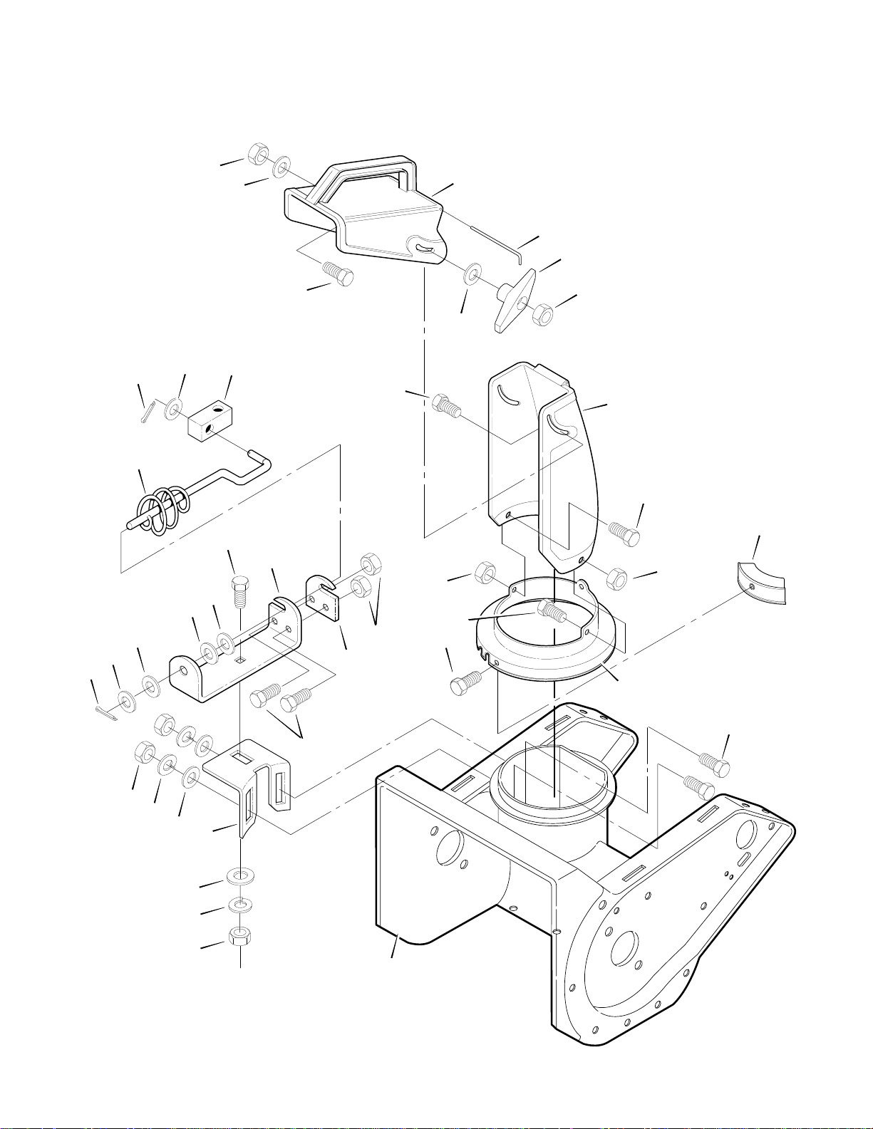
Page 29

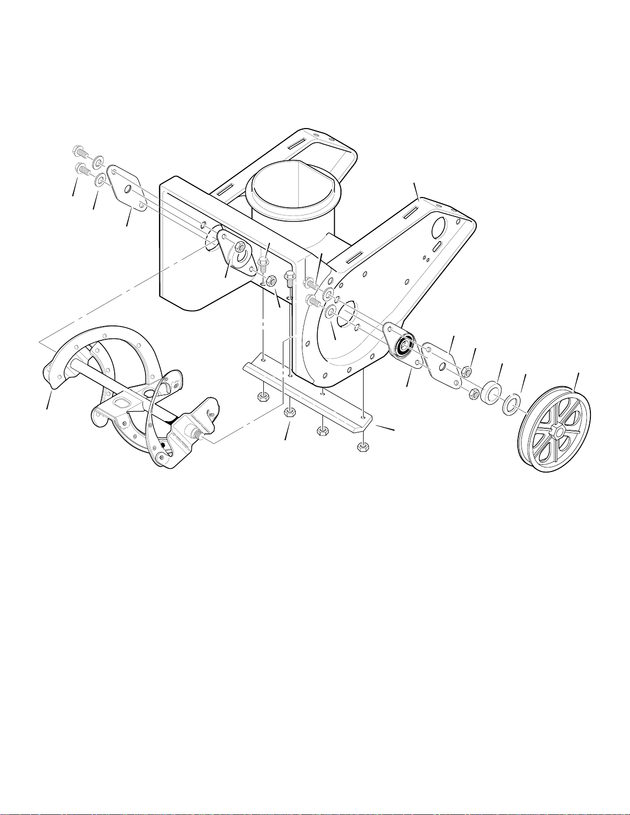
FRONTIER MODEL ST0521M
FACTORY MODEL 621501x16NA
FRONTIER MODEL ST0521E
Key No. Part No. Description
1 MT760632
MT760631
2 MT340381E701 AUGER HOUSING, 21”
3 MT313780 SCREW, .31-18x .5
4 MT301419E701 SUPPORT, FRAME
5 MT301415E701 SUPPORT, ENGINE
6 MT71391 NUT.31-18 HEX
7 MT71391 NUT .31-18 HEX
9 MT314135 HANDLE, UPPER
10 MT314142 COVER, CABLE SPRING
11 MT316001 CABLE, DRIVE
12 MT73826 LOCKNUT .25-20 HEX
13 MT71067 WASHER .286-0.62-.07
14 MT70971 SCREW .25-20x1.50
15 MT71060 WASHER .318-0.56-.05
16 MT313676 SCREW, .31-18x .63
17 MT301421 PLATE, REAR
18 MT45892 BOLT, CARRIAGE .38-16x1.50
19 MT339017 SPRING, IDLER BRAKE
20 MT333784 PULLEY, 4.5 HP
21 MT333805 BOLT, SHOULDER .625x.280
22 MT71391 NUT.31-18 HEX
23 MT120386 WASHER, FLAT .312X .73X.065
24 MT340428 GUIDE, BELT
25 MT590 JAM NUT.38-16 HEX
26 MT48924 PULLEY, IDLER
27 MT37x130 BELT, POLY-V 10 RIB 35.14
28 MT333594 BOLT, SHOULDER
29 MT339415 BRACKET, IDLER ARM
-- MTF-031039C OWNER’S MANUAL
FACTORY MODEL 621500x16NA
ENGINE ASSEMBLY
ENGINE, RECOIL START
ENGINE, ELECTRIC START
MTF-031039C
29
Page 30

FRONTIER MODEL ST0521M
FACTORY MODEL 621501x16NA
FRONTIER MODEL ST0521E
9
8
2
10
11
15
16 14
7
18
17
6
FACTORY MODEL 621500x16NA
FRAME ASSEMBLY
12
13
19
20
15
11
21
5
4
3
2
1
25
22
17
18
23
24
5
11
25
MTF-031039C
11
25
11
26
25
11
30
Page 31

FRONTIER MODEL ST0521M
FACTORY MODEL 621501x16NA
FRONTIER MODEL ST0521E
Key No. Part No. Description
1 MT340381E701 AUGER HOUSING 21”
2 MT323387 CLAMP, TUBING
3 MT323395 TUBING, FUEL
4 MT56679 FILTER, FUEL
5 MT313780 SCREW .31-18x.50
6 MT323363 TUBING, FUEL
7 MT47345 CLAMP, TUBING
8 MT326142 FUEL TANK
9 MT327018 CAP, FUEL
10 MT311671 CLAMP, WORM DR
11 MT309814 SCREW 10-24x.62
12 MT308677 BRACKET, FUEL TANK
13 MT997316 NUT, LOCK 10-24
14 MT274707 SCREW 10-24x.50
15 MT318139 SCREW .25-20x.62
16 MT301420E701 PLATE, REAR MT RH
17 MT71391 NUT, LOCK .31-18
18 MT313676 SCREW .31-18x.75
19 MT301419E701 FRAME SUPPORT
20 MT311738E701 HEAT SHIELD
21 MT760631 ENGINE w/ELECTRIC START
22 MT301421E701 PLATE, REAR MT LH
23 MT302635 NUT, LOCK .25-20
24 MT303041 WASHER, FLAT
25 MT590 NUT.38-16 HEX JAM CTRLK
26 MT305869 BOTTOM SHROUD
FACTORY MODEL 621500x16NA
FRAME ASSEMBLY
MTF-031039C
31
Page 32

FRONTIER MODEL ST0521M
FACTORY MODEL 621501x16NA
FRONTIER MODEL ST0521E
1
18
16
17
FACTORY MODEL 621500x16NA
HANDLE ASSEMBLY
3
4
6
9
5
8
6
7
10
15
14
15
15
14
15
12
13
11
9
17
Key No. Part No. Description Key No. Part No. Description
1 MT307747 DRIVEBAR
3 MT309815 SCREW 10-24x1.00
4 MT329935 KNOB
5 MT308716 BRACKET, UPPER CRANK
6 MT311936 WASHER, FORMED
7 MT314135 HANDLE, UPPER w/FOAM
8 MT308715 BRACKET, LOWER CRANK
9 MT337584 BOLT, FORMED HEAD
10 MT310169 SCREW .25-20x.62
MTF-031039C
11 MT71055 NUT, LOCK 10-24
12 MT301421E701 PLATE, REAR MT LH
13 MT301419E701 FRAME SUPPORT
14 MT71391 NUT, LOCK .31-18
15 MT71060 WASHER, LOCK
16 MT301420E701 PLATE, REAR MT RH
17 MT313676 SCREW .31-18x.75
18 MT309964E701 LOWER HANDLE
32
4
Page 33
FRONTIER MODEL ST0521M
FACTORY MODEL 621501x16NA
FRONTIER MODEL ST0521E
1
2
3
4
1
5
FACTORY MODEL 621500x16NA
AUGER HOUSING
6
1
3
5
2
7
8
9
12
MTF-031039C
4
10
11
Key No. Part No. Description
1 MT579052 SCREW .25-20X.63
2 MT71067 WASHER, FLAT .281x.63x.065
3 MT54836 PLATE, BEARING RETAINER
4 MT583459 PLATE & BEARING ASSY
5 MT73826 NUT, LOCK .25-20
6 MT340381E701 AUGER HOUSING 21”
7 MT578101 SPACER, SLEEVE
8 MT40677 WASHER, FLAT .640x1.25x.06
9 MT333446 PULLEY, POLY V
10 MT302418 SCRAPER BLADE
11 MT302635 NUT, LOCK .25-20
12 MT321961E701 AUGER ASSY
33
Page 34
FRONTIER MODEL ST0521M
FACTORY MODEL 621501x16NA
FRONTIER MODEL ST0521E
15
16
17
6
5
14
13
22
FACTORY MODEL 621500x16NA
DISCHARGE CHUTE
18
19
20
21
16
23
24
28
8
9
6
7
7
6
5
10
1
2
3
4
3
2
12
11
25
24
26
25
27
29
MTF-031039C
1
30
34
Page 35

FRONTIER MODEL ST0521M
FACTORY MODEL 621501x16NA
FRONTIER MODEL ST0521E
Key No. Part No. Description
1 MT15X144 NUT.31-18 HEX
2 MT71060 WASHER, LOCK
3 MT71071 WASHER, FLAT .349-0.69-.07
4 MT302505E701 BRKT, WORM ADJUST
5 MT71081 PIN, COTTER.094x0.75L
6 MT12452 WASHER, FLAT .400-0.75-.02
7 MT313431 WASHER, SPRING .395-0.73-.01
8 MT340720 BOLT-CARRIAGE .31-18x0.75
9 MT300728E701 BRKT, CHUTE ROD HOLE
10 MT313686 SCREW.25-20x0.50 HHC
11 MT307741 PLATE, CHUTE ROD
12 MT73826 NUT, LOCK.25-20 HEX
13 MT51564 BLOCK, PIVOT CHUTE
14 MT307742 ROD ASSEMBLY, LOWER CHUTE
15 MT71391 NUT, LOCK .31-18 HEX
16 MT71071 WASHER, FLAT .349-0.69-.07
17 MT578088 SCREW.31-18x0.75
18 MT305861 CHUTE, UPPER
19 MT310562 WIRE FORM, HINGE
20 MT57171 WINGKNOB
21 MT15X144 NUT.31-18 HEX
22 MT302843 BOLT-CARRIAGE .31-18x1.50
23 MT305862 CHUTE, LOWER
24 MT313686 SCREW.25-20x0.50
25 MT15X143 NUT, FLANGED LOCK .25-20
26 MT56962 SCREW.25-14x0.62
27 MT307842 CHUTE RING
28 MT300790 CLIP, CHUTE RING
29 MT340720 BOLT-CARRIAGE .31-18x0.75
30 MT340381E701 AUGER HSG, 21”
FACTORY MODEL 621500x16NA
DISCHARGE CHUTE
MTF-031039C
35
Page 36
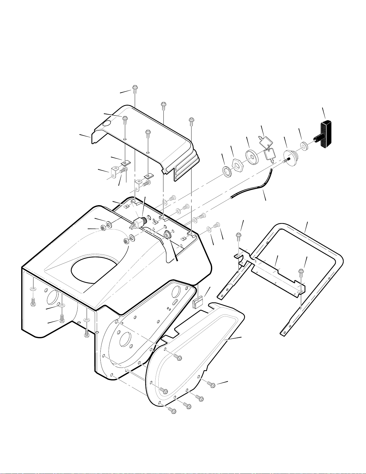
FRONTIER MODEL ST0521M
FACTORY MODEL 621501x16NA
FRONTIER MODEL ST0521E
10
9
8
5
7
6
5
11
FACTORY MODEL 621500x16NA
TOP COVER ASSEMBLY
18
15
14
13
12
19
17
16
4
3
19
22
2
1
20
20
23
26
25
24
20
MTF-031039C
36
Page 37

FRONTIER MODEL ST0521M
FACTORY MODEL 621501x16NA
FRONTIER MODEL ST0521E
Key No. Part No. Description
1 MT309813 SCREW 10-14x.63
2 MT711666 WASHER, FLAT
3 MT71055 NUT, LOCK 10-24
4 MT303041 WASHER, FLAT
5 MT309811 NUT, U TYPE
6 MT12342 SCREW 10-24x.50
7 MT312102 BRACKET, ACCESS COVER
8 MT305871 COVER, ENGINE ACCESS
9 MT312094 SCREW 10-16x.62
10 MT312362 SCREW 10-16x.75
11 MT56992 INGNITION SWITCH
12 MT313683 WASHER, INTERNAL LOCK
13 MT300193 NUT, .62-32 PLASTIC
14 MT300194 BOOT, SWITCH
15 MT49643 KEYS & RING
16 MT54601 PRIMER BULB
17 MT57587 GROMMET & WASHER
18 MT333643 KNOB, STANDARD T
19 MT1259 HOSE, PRIMER
20 MT309814 SCREW 10-24x.63
21 MT303008 NUT .25-20 KEPS
22 MT313057 S CLIP
23 MT397761 BRACKET, SHROUD MTG
24 MT309964E701 LOWER HANDLE
25 MT310798 SCREW 10-24x.38
26 MT302416 COVER, BELT
FACTORY MODEL 621500x16NA
TOP COVER ASSEMBLY
MTF-031039C
37
Page 38
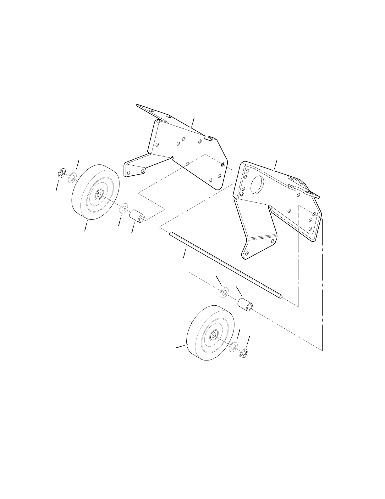
FRONTIER MODEL ST0521M
FACTORY MODEL 621501x16NA
FRONTIER MODEL ST0521E
2
1
FACTORY MODEL 621500x16NA
WHEEL ASSEMBLY
7
6
3
2
4
5
2
4
2
1
3
Key No. Part No. Description
1 MT577598 RING, RET. E
2 MT71072 WASHER, FLAT .406x.81x.07
3 MT1501741 7.75”X1.75” WHEEL
4 MT309656 SPACER, SLEEVE
5 MT307719 AXLE SHAFT
6 MT301421E701 PLATE, REAR MT LH
7 MT301420E701 PLATE, REAR MT RH
MTF-031039C
38
Page 39

FRONTIER MODEL ST0521M
FACTORY MODEL 621501x16NA
FRONTIER MODEL ST0521E
8
7
6
FACTORY MODEL 621500x16NA
CHUTE ROD ASSEMBLY
9
10
1
5
2
3
4
Key No. Part No. Description
1 MT331532 PUSH NUT
2 MT307755 KNOB, GRIP
3 MT12452 WASHER, FLAT .400x.75x.02
4 MT71081 PIN, COTTER
5 MT307742 ROD, CHUTE CNTRL LWR
6 MT51564 BLOCK, PIVOT
7 MT307756 ROD, CHUTE CNTRL MID
8 MT314159 NUT, LOCK 10-32
9 MT314158 SCREW, 10-32X.88
10 MT309449 ROD, CHUTE UPPER
MTF-031039C
39
Page 40
FRONTIER MODEL ST0521M
FACTORY MODEL 621501x16NA
FRONTIER MODEL ST0521E
2
FACTORY MODEL 621500x16NA
DECALS
3
4
5
1
7
6
Key No. Part No. Description
1 MT48x5262 DECAL, DANGER AUGER
2 MT48x2034 DECAL, DANGER CHUTE
3 MT337524 DECAL, AUGER CONTROL
4 MT340709
MT340708
5 MT69880 DECAL, HOT MUFFLER
6 MT48x5260 DECAL, FRONTIER ST0521
7 MT48x5202 DECAL, EPA
* MTF-031039C OPERATOR’S MANUAL
DECAL, CONTROL PANEL ST0521E (621500x16NA)
DECAL, CONTROL PANEL ST0521M (621501x16NA)
MTF-031039C
* Not Illustrated
40
Page 41

FRONTIER MODEL ST0521E FACTORY MODEL 621500x16NA
ELECTRIC STARTER
Ref. Hardware
(Bolts)
1
Ref. Electric
Starter
6
Ref. Engine
Ref. Top Cover
5
2
4
3
MTF-031039C
Key No. Part No. Description
1 NA INCLUDED WITH ENGINE
2 MT271163 NUT, KEPS 8-32
3 MT414106 WASHER, FLAT
4 MT311633 SCREW 8-32x3.00
5 MT56023 CORD, EXTENSION
6 MT57569 RETAINER
41
Page 42

NOTES
MTF-031039C
42
Page 43

NOTES
MTF-031039C
43
Page 44

SPECIFICATIONS ST0521M, ST0521E
Engine Tecumseh Snow King 2-Cycle
Horsepower 5 hp
Starter ST0521M Recoil
ST0521E Electric
Fuel Capacity 1.5 quart
Drive System Auger
Tire Diameter 7”
Clearing Width 21”
Housing Height 12”
Auger Diameter 9”
Auger Type Rubber-edged
Chute Rotation Remote
Chute Turning Radius
Deflector Control Manual
Weight ST0521M 89 lbs
ST0521E 93 lbs
Warranty - Engine 2 years
Warranty - Machine 3 years
190_
MTF-031039C
44
 Loading...