

Page 1
JOHN DEERE 4100, 4110 and 4115
Page 1
CAB MOUNTING INSTRUCTIONS
Fits 410 loaders with 2 post non-folding ROPS
A-11170
Manufactured by:
BOX 718 • LITCHFIELD, MINNESOTA 55355
(320) 693-3221 Fax: (320) 693-7252
www.800cabline.com
05-10324
June 2003
Page 2

SAFETY INSTRUCTIONS
Page 2
Read operator’s manual. Be thoroughly familiar with the controls, capabilities, and proper
use of the equipment.
NEVER ALLOW ANY RIDERS.
IMPORTANT: This cab must only be used on tractors outfitted with a NON-FOLDING
ROPS.
DO NOT place this cab on a tractor outfitted with a folding ROPS.
DO NOT remove the top half of a folding ROPS to accommodate this cab.
Thoroughly inspect cab mounting periodically.
Stay alert for hidden hazards and traffic.
Avoid sudden starts, excessive speeds, and sudden stops when operating on hillside,
rough ground and most off-the-road operations.
Use extreme care when working close to fences, ditches, or on hillsides.
Wait for tractor to STOP before dismounting.
Check clearance carefully before driving under any objects.
Avoid operating sideways on a steep slope whenever possible.
ALWAYS buckle safety belt while operating tractor.
Never exceed factory recommended specifications.
DO NOT weld, cut, drill or modify ROPS in any manner unless instructed by manufacturer.
05-10324
June 2003
Page 3
Mounting Instructions
#8
639
Page 3
John Deere 4100, 4110 and 4115
1. PREPARATION OF TRACTOR;
A. Remove grab handles from tractor fenders.
B. Disconnect battery power.
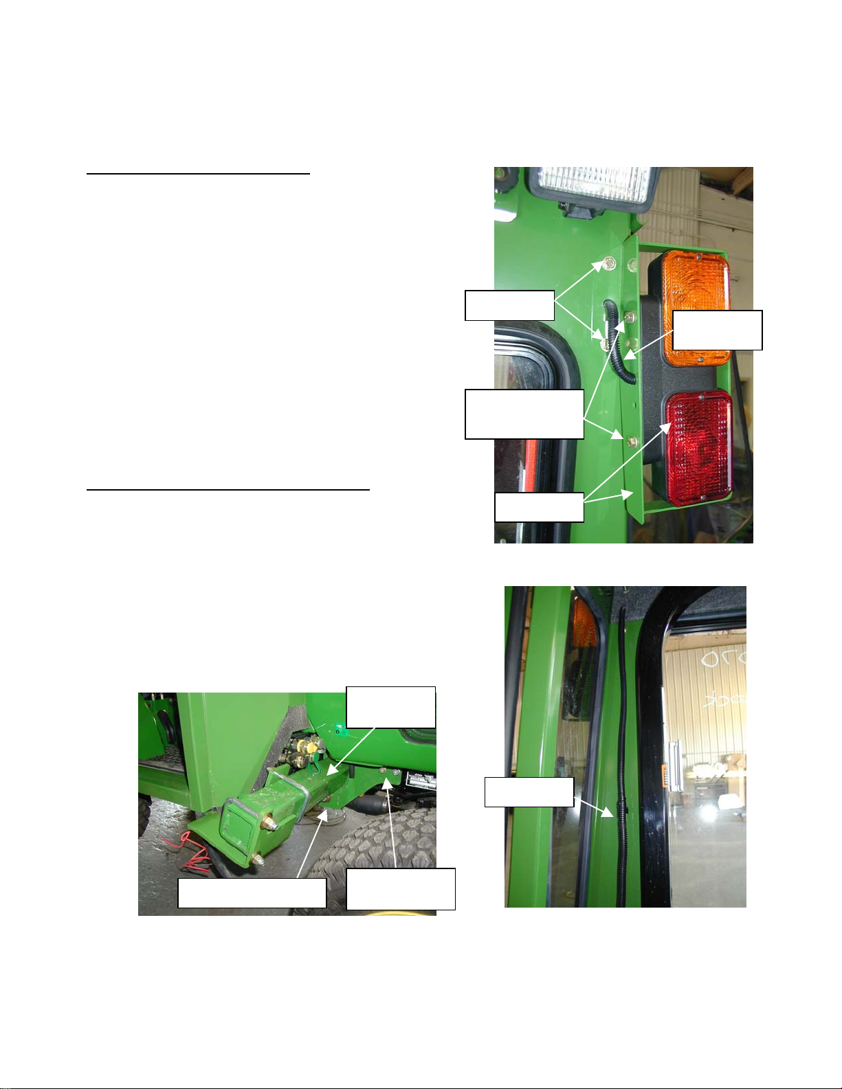
C. Remove rear warning lights from roll bar.
Attach warning lights to cab using (1) LH #715662 and (1) RH #7-15661 dual light
mounting brackets. Secure lights to bracket
with; (See Figure 1C).
(4) 8mm x 25mm cap-screws
(4) 5/16” lock washers
D. Secure brackets to cab, on each side using;
(4) ¼-20unc capscrews
(4) ¼-20unc nyloc nuts
(8) ¼” flat washers
E. Install Dual Light Wire Extension Kit #8-
14639 to route wires into cab and down each
side of the interior cab wall. See Figure 1C
and 1E.
F. Remove side engine panels and hood.
2. INSTALLING THE CAB MOUNT PLATES;
G. Note: Loader brackets must be
purchased from John Deere in order to
mount the front cab mount plates.
H. Attach JD Loader Brackets to each side of
the tractor frame using and secure with;
(6) 10mm x 35mm bolts
(6) 7/16” lock washers
(4) 7/16-14unc x 1” long bolts
(4) 7/16” lock washers
(4) 7/16-14unc Nyloc Nuts
See Figure 2H.
NOTE 1D
NOTE 1E
-14
8MM x 25MM
Cap-screws
NOTE 1C
Figure 1C
JD Loader
Bracket
10mm x 35mm Bolts
Figure 2H
NOTE 1C
7/16- 14unc x
1” Bolts
Figure 1E
05-10324
June 2003
Page 4
Mounting Instructions
#3
8
#6-3946
ote
Page 4
John Deere 4100, 4110 and 4115
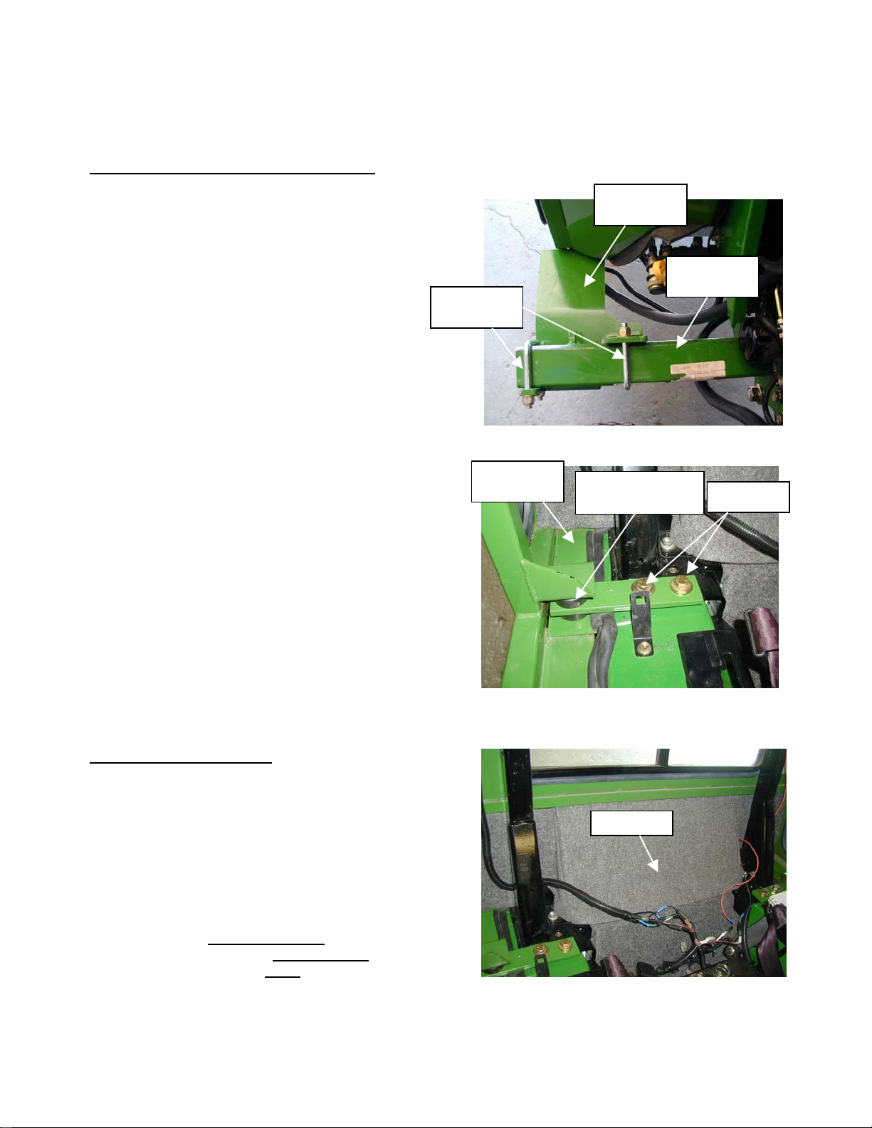
2. MOUNTING THE CAB MOUNT PLATES;
I. Mounting Front Cab Mount Plates;
For 4100 and 4110 models, attach left
mount #6-39308 and right mount #639309 to the JD Loader Brackets, just
installed in step “H”. See Figure 2H.
For 4115 models, attach left mount #6-
42584 and right mount #6-42585.
J. Secure front cab mount plates with;
(4) ½-13unc U-bolts
(8) ½” flat washers
(8) ½-13unc nyloc-nuts.
See Figure 2J.
K. Remove (2) bolts (on each side) from the roll
bar mount. See Figure 2K. Install rear
mounting bracket #6-39310 on each side of
unit. Secure with;
(4) 12mm x 50mm bolts
(4) ½” flat washers
(4) ½” lock washers
L. Install (4) Rubber isolator bushing in front and
rear mounts. NOTE: Isolator mounts (#3-
16635) with pipe bushing should be inserted
from the top side of mount.
M. Adjust seat forward, tilt and remove hinge pin
and seat. Attach rear seal panel assembly
#8-14239 using (2) existing holes in the roll
bar cross member and secure with;
(2) ¼”-20unc x 1” long bolts
(2) ¼” flat washers
(2) ¼”-20unc Nyloc Nuts
See Figure 3M.
Some trimming of fabric may be needed to
achieve proper fit of real seal panel. Reinstall
seat and seat pivot pin.
U-Bolt
-1727
Seal Panel
Cab Mount
Plate
JD Loader
Bracket
Figure 2J
1
Note 2L, 3N &
3O
Figure 2K
Note 2K
3. INSTALLATION OF CAB
N. Remove cab from shipping stand. Lower cab
over roll bar until cab contacts front and rear
isolator bushings. See Figure 2K and 3M.
O. Secure cab to bushings with;
(4) ½” Snubbing Washers
Seal Panel #6-39461 will be secured from the
bottom side of the rubber mount with the
fasteners noted above. See Figure 2K.
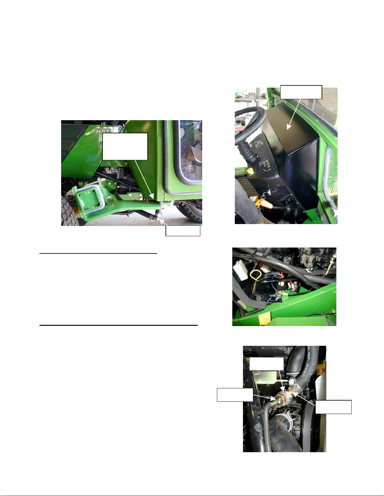
P. Install front hood panel;
Secure hood panel with;
(4) ½-13unc x 3.0” long Bolts
(4) ½-13unc Nyloc Nuts
For models 4100 and 4115: #8-14240
For model 4110: #8-14649
(2) ¼-20unc x 1” bolts
(2) ¼-20unc nylock nuts (See Figure 3P)
N
2M
Figure 3M
05-10324
June 2003
Page 5
Mounting Instructions
(
)
ote 5
Page 5
John Deere 4100, 4110 and 4115
Q. Install right and left floor mats on each side.
R. Remove Slow Moving Vehicle sign and
bracket from tractor seat. Re-mount sign and
bracket using holes located on the back-left
side of cab.
Isolator
Bushing
#3-16635
Note 3P
Figure 3M
4. ELECTRICAL HOOKUP (All Models)
A. Mount #3-17803 Universal Wire Relay
Breaker Kit in the engine compartment area.
Bracket #6-42329 may be used if room
permits. See Figure 4A.
B. Refer to drawing #3-17803 and # 8-14376 for
additional electrical connections and details.
C. Make sure the cab is grounded to frame by
installing cab to ground wire #8-14258.
5. HEATER HOSE HOOKUP (Ref. Drawing #8-14232)
A. Drain coolant from radiator and engine block.
B. Remove temperature sensor from thermostat
housing area.
C. Install aluminum fitting #3-15815 with O-ring
washer #3-16823 into thermostat housing.
See Figure 5C.
D. Re-install temperature sensor into the
aluminum fitting just installed (Step 5C).
E. Install hose to NPT fitting #3-12119 into the
side port of the aluminum fitting.
F. Measure and cut the 5/8” heater hose that
routes (Supply Line) from the left (Driver) side
of the cab to the thermostat-aluminum-hose
nipple fitting. Plastic elbow #3-10282 should
be used at the bottom of the cab tubes. See
Figure 3M.
N
F
Figure 3P
4110 hood shown
Figure 4A
Note 5C
Note 5D
Note 5E
Figure 5C
05-10324
June 2003
Page 6
John Deere 4100, 4110 and 4115
(
)
(
)
Page 6
Mounting Instructions
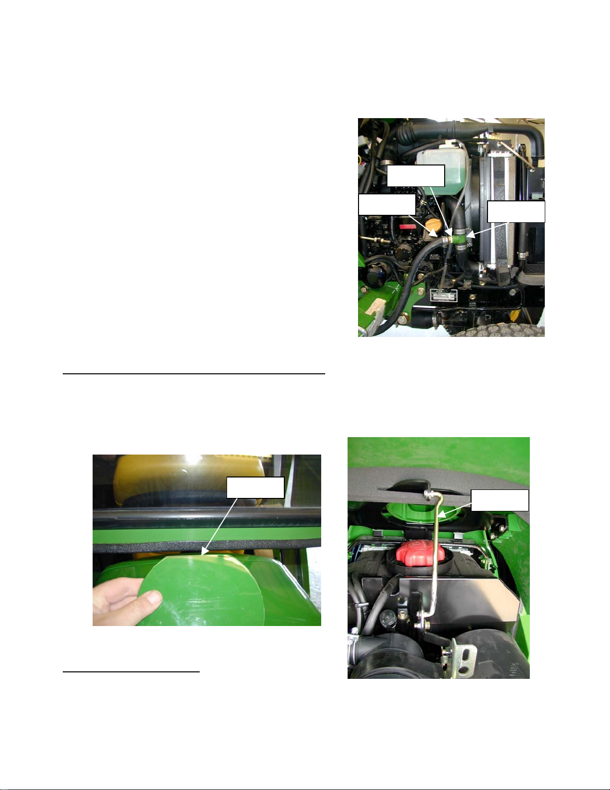
G. The lower radiator hose will need to be cut for
installation of the lower radiator hose “T”
fitting #7-11308. See Figure 5G.
H. Install 5/8” hose to NPT fitting #3-12119 into
the lower radiator hose “T” fitting. See Figure
5G.
I. Measure and cut the 5/8” heater hose from
the right side (Return Line) of the cab with the
90-degree elbow #3-10282 to the lower
radiator hose “T” nipple fitting. See Figure
5G.
J. Tighten all hose connections with hose
clamps.
K. Re-connect Battery Power.
L. Refill radiator. Start engine and run at fast
idle to purge air from coolant system. Make
sure the Heat-Pull Lever is pulled out (Turned
On).
M. Check for leaks.
N. Check coolant level after heater core and
hoses are filled.
Note 5I
Note 5H
Note 5G
Figure 5G
6. ADDITIONAL INSTRUCTIONS (4110 models, ONLY!)
A. Since the 4110 hood slightly differs from the 4100 and 4115, the fuel cap lid needs to be
modified. Remove ¾” from the end of the fuel cap lid as shown in Figure 6A.
B. The 4110 hood also sets back further towards the cab and therefore the hood will not open as
far as the other models. Install the shorter hood rod #7-15714 to prevent the hood from
contacting the cab. See Figure 6B.
Note 6A
Figure 6A
4110 Models ONLY
Note 6B
7. VERTICAL EXHAUST KIT
A. For applications that require a high exhaust
system, over the head of the operator, a
vertical exhaust kit is available through you
local John Deere dealer.
Figure 6B
4110 Models ONLY
05-10324
June 2003
Page 7

John Deere 4100, 4110 and 4115
Page 7
Mounting Instructions
Drawing Index
8-14172 CAB ASSEMBLY
8-14173 DOOR ASSEMBLY RIGHT
8-14174 DOOR ASSEMBLY LEFT
8-14630 HEADLINER ASSEMBLY
8-14176 MOUNT KIT -COMMON
8-14241 MOUNT KIT FOR 4100
8-14647 MOUNT KIT FOR 4110
8-14648 MOUNT KIT FOR 4115
8-14232 HEATER KIT
8-14376 ELECTRICAL SCHEMATIC
3-17803 WIRE RELAY BREAKER HARNESS
8-14639 WIRE EXTENSION FOR DUAL LIGHTS
05-10324
June 2003
Page 8

John Deere 4100, 4110 and 4115
Y
Page 8
A-11170 Replacement Parts
8-14172 Cab Assembly
ITEM QT
PART NO. DESCRIPTION
1 1 7-15074 Cab Weldment
2 4 3-15917 Right Upper Door Glass
3 1 8-14173 Right Door Assembly
4 1 8-14174 Left Door Assembly
5 1 8-14630 Headliner Assembly
6 2 3-10166 .437 Flat Washer
7 2 3-10472 .437-14 Nyloc Hex Nut
8 1 3-15944 Filter, 2.19 x 3" x 20.88"
9 2 3-15407 Striker Stud & Washer
10 1 6-37535 Air Filter Cover
11 1 3-11099 Wiper Motor
12 1 3-15776 Wiper Arm
13 1 3-15763 Wiper Blade
14 10 FT 3-10649 Window Rubber
15 2 FT 3-10649 Window Rubber, 2 FT
16 9 FT 3-10649 Window Rubber
17 7 FT 3-10649 Window Rubber
18 7 FT 3-10649 Window Rubber
19 2 3-17176 Side Rear Glass
20 2 3-17177 Lower Front Glass
21 1 3-17173 Front Windshield Glass
22 1 3-16652 Rear Sliding Window Assembly
23 1 6-39855 Rear Headliner Insulation
24 1 6-39856 Right Rear Side Headliner Insulation
25 1 6-39857 Left Rear Side Headliner Insulation
26 1 6-39859 Top Rear Panel Insulation
27 1 6-39860 Bottom Center Rear Insulation
28 1 6-39861 Left Rear Bottom Insulation
29 1 6-39862 Bottom Right Rear Insulation
30 1 6-39864 Lower Left Front Insulation
31 1 6-39865 Lower Right Front Insulation
32 1 7-15208 Roof Weldment
33 2 3-15573 Black Plastic Knob
34 2 6-20618 Lifting Ear
35 2 3-10087 .500 Flat Washer
36 2 3-10079 .500 Lock Washer
37 2 3-10129 Hex-Head Bolt, 1/2-13 NC X 1" Long, Grd 5
38 2 3-10077 .312 Lock Washer
39 2 3-11821 Gas Spring Ball Stud
40 2 3-13024 6" Stroke Gas Spring
41 2 3-10135 Machine Screw, #10-24 X 1.00 TH SL
05-10324
June 2003
Page 9

John Deere 4100, 4110 and 4115
Page 9
A-11170 Replacement Parts
8-14172 Cab Assembly (Continued)
ITEM QTY PART NO. DESCRIPTION
42 2 3-10083 .187 Flat Washer
43 2 3-10308 Nyloc Hex Nut, #10-24 NC
44 4 3-14387 .25-20 NC Nut Sert
45 4 3-10076 .250 Lock Washer
46 4 3-10220 Hex-Head Bolt, 1/4-20 NC X 1" Long, Grd 5
47 2 3-10282 Plastic Elbow
48 3 3-10858 #10 Hose Clamp
49 4 FT 3-11264 Sponge Polyfoam
50 2 3-11172 Heater Hose
51 1 3-10610 Seal Rubber, Clip-on Bubble, 180 Degrees
52 1 3-15952 Seal Rubber, 3/4" OD Bubble, Up TO 1/8" Material
53 1 3-15952 Seal Rubber, 3/4" OD Bubble, Up TO 1/8" Material
54 1 3-10610 Seal Rubber, Clip-on Bubble, 180 Degrees
55 1 3-10610 Seal Rubber, Clip-on Bubble, 180 Degrees
56 1 3-12138 Trim Seal, 7/16 OD Bubble, 1/8 Mat
05-10324
June 2003
Page 10

Page 10
Page 11

Page 11
Page 12

John Deere 4100, 4110 and 4115
Page 12
A-11170 Replacement Parts
Right Door Assembly 8-14173
ITEM QTY PART NO. DESCRIPTION
1 1 7-15075 Right Door Weldment
2 1 3-17178 Upper Door Glass
3 1 3-17179 Lower Door Glass
4 3 3-12692 Hex-Head Bolt, M6-15 x 1" Long, Gr 8.8
5 3 3-10076 .250 Lock Washer
6 1 3-15640 Latch, Rotary
7 4 3-10106 .250-20 NC X .630 Machine Screw
8 1 3-14231 Knob
9 1 3-10078 .375 Lock Washer
10 1 3-10147 .375-16 NC x 1.00 Hex Head Cap Screw
11 1 3-10065 .375-16 NC Hex Nut
12 1 3-11821 Ball Stud
13 1 3-10077 .312 Lock Washer
14 1 3-10064 .312-18 NC Hex Nut
15 14.3 FT 3-15952 Trim Seal 90 degree bubble
16 9.0 FT 3-10649 Window Rubber, Upper Right
17 6.9 FT 3-10649 Window Rubber, Lower Right
18 1 3-15574 Handle, Exterior
05-10324
June 2003
Page 13

Page 13
Page 14

John Deere 4100, 4110 and 4115
Page 14
A-11170 Replacement Parts
Left Door Assembly 8-14174
ITEM QTY PART NO. DESCRIPTION
1 1 7-15076 Left Door Weldment
2 1 3-15567 Latch, Rotary
3 1 3-17178 Upper Door Glass
4 1 3-17179 Lower Door Glass
5 1 3-11821 Ball Stud
6 1 3-10077 .312 Lock Washer
7 1 3-10064 .312-18 NC Hex Nut
8 4 3-10106 .250-20 NC X .630 Machine Screw
9 1 3-10147 .375-16 NC x 1.00 Hex-Head Cap Screw
10 1 3-10078 .375 Lock Washer
11 1 3-10065 .375-16 NC Hex Nut
12 1 3-14231 Knob
13 3 3-10076 .250 Lock Washer
14 3 3-12692 M6 x 1.00 Hex-Head Cap Screw
15 9.0 FT 3-10649 Window Rubber, Upper Left
16 6.9 FT 3-10649 Window Rubber, Lower Left
17 14.3 FT 3-15952 Seal Rubber, 3/4" OD Bubble, Up to 1/8" Material
18 1 3-15574 Handle, Exterior
05-10324
June 2003
Page 15

Page 15
Page 16

John Deere 4100, 4110 and 4115
Page 16
A-11170 Replacement Parts
Headliner Assembly 8-14630
ITEM QTY PART NO. DESCRIPTION
1 1 7-15105 Headliner weldment
2 2 3-11202 Blower Gasket
3 1 3-15935 Dual Wheel Blower
4 1 3-16572 Heater Core
5 2 3-16672 Heater Core Flange Frame Clip
6 1 3-16232 Dome light, 12V
7 1 3-16692 Heater Temp. Control Valve
8 1 3-16033 Fuse Block
9 3 3-15594 Round Louver
10 1 3-16580 ATO/ATC Fuse, 30 AMP
11 7 3-10858 #10 Hose Clamp
12 1 FT 3-11172 Heater Hose
13 1 6-37263 Wiper & Lights Switch Plate
14 10 3-11812 Self tap Screw, #10 x 6.25
15 1 6-37482 Switch Mounting Plate
16 1 6-36057 Fuse Cover
17 2 3-16677 Rocker Switch Hole Plug
18 1 6-39854 Center Headliner Insulation
19 4 3-10729 Snap Bushing Grommet
20 2 3-10099 Machine Screw, #10-24 NC X 1.50
21 2 3-10308 Nyloc Hex Nut, #10-24 NC
22 1 FT 3-11172 Heater Hose
23 5 FT 3-11172 Heater Hose
24 7 FT 3-11172 Heater Hose
25 2 3-15928 Black Round Louver
26 1 3-11149 Heater Control Assembly Cable
27 2 3-11738 Grommet, 1.125 Dia. MTG Hole
28 2 3-16984 Machine Screw, #6-32 NC X 1.50 RH SL
29 2 3-12637 Hex Nut, #6-32 NC
30 2 3-12638 Washer, #6 Lock
31 1 3-16274 Rocker Switch
32 1 3-15432 Rotary Switch
33 1 3-11173 Blower Switch Knob
34 1 3-11741 Plug, Hole, Plastic, .750 Dia.
35 1 6-39858 Front Headliner Insulation
05-10324
June 2003
Page 17

Page 17
Page 18

John Deere 4100, 4110 and 4115
Page 18
A-11170 Replacement Parts
Mount Kit -Common 8-14176
ITEM QTY PART NO. DESCRIPTION
1 2 6-39310 Rear Mount
2 2 6-39461 Rear Mount Seal
3 1 3-17871 Left Floor mat
4 1 3-17872 Right Floor mat
5 1 3-10002 Hex-Head Bolt, 1/4-20 NC X 5/8" Long, Grd 5
6 3 3-10070 Nyloc Hex Nut, .250-20 NC
7 4 3-10077 .312 Hel Spring Lock Washer
8 6 3-10079 .500 Hel Spring Lock Washer
9 2 3-10084 .250 Flat Washer
10 12 3-10087 .500 Flat Washer
11 4 3-10123 Hex-Head Bolt, M8-25 X 1-1/4" Long, Grd 8.8
12 4 3-10131 Hex-Head Bolt, .50-1 3 NC x 3.00, Grade 5
13 4 3-10220 Hex-Head Bolt, 1/4-20 NC X 1" Long, Grd 5
14 12 3-10379 Nyloc Hex Nut, .50-113 NC
15 4 3-13295 Hex-Head Bolt M 12 x 30 x 1.75 C 933 C 10.9
16 4 3-16635 Rubber Mount
17 1 05-10324 Mounting Instructions
18 4 3-16636 Snubbing Washer 1/2"
19 1 8-14232 Heater Hook Up Kit
20 1 8-14239 Rear Seal Panel Asy
21 3 3-11812 Self tap screw
22 1 6-39863 Insulation
23 4 FT 3-15068 Seal Rubber, 3/8" OD Bubble, Up to 1/8" Material
24 1 6-42329 Relay Breaker Mount
25 4 3-17278 U-Bolt, ½-13unc
26 2 8-14639 Dual light wire extension kit
27 1 3-17803 Universal wire breaker relay harness
28 1 7-15661 LH Dual Light Mount
29 1 7-15662 RH Dual Light Mount
05-10324
June 2003
Page 19

Page 19
Page 20

John Deere 4100, 4110 and 4115
Page 20
A-11170 Replacement Parts
Replacement Parts List
Mount Kit for 4100
8-14241
ITEM QTY PART NO. DESCRIPTION
1 1 6-42584 Left Front Mount Plate 4100 and 4110
2 1 6-42585 Right Front Mount Plate 4100 and 4110
3 1 8-14240 Hood Panel for 4100 and 4115
Replacement Parts List
Mount Kit for 4110
8-14647
ITEM QTY PART NO. DESCRIPTION
1 1 6-42584 Left Front Mount 4100 and 4110
2 1 6-42585 Right Front Mount 4100 and 4110
3 1 8-14649 Hood Panel for 4110 -ONLY
Replacement Parts List
Mount Kit for 4115
8-14648
ITEM QTY PART NO. DESCRIPTION
1 1 6-42584 Left Front Mount Plate for 4115 -ONLY
2 1 6-42585 Right Front Mount Plate for 4115 -ONLY
3 1 8-14240 Hood Panel for 4100 and 4115
05-10324
June 2003
Page 21

Page 21
Page 22

Page 22
Page 23

Page 23
Page 24

John Deere 4100, 4110 and 4115
Page 24
A-11170 Replacement Parts
Heater Kit 8-14232
ITEM QTY PART NO. DESCRIPTION
1 1 7-11308 Heater Tee Weldment
2 2 3-10282 90 degrees Plastic Tee
3 4 3-10725 Nylon Wire Ties
4 6 3-10858 # 10 Hose Clamp
5 8 FT 3-11172 Heater Hose
6 1 3-15815 Aluminum Adapter Fitting
7 2 3-13442 # 16 Hose Clamp
8 1 3-16823 O-Ring
9 2 3-12119 3/8-18 NPT TO 5/8 HOSE NIPPLE
05-10324
June 2003
Page 25

Page 25
Page 26

Page 26
Page 27

Page 27
Page 28

Page 28
 Loading...