


JENN-AIR® BOTTOM MOUNT
BUILT-IN REFRIGERATOR
REFRIGERADOR EMPOTRADO CON CONGELADOR EN LA PARTE INFERIOR DE JENN-AIR®
RÉFRIGÉRATEUR ENCASTRÉ AVEC CONGÉLATEUR EN BAS JENN-AIR®
INSTALLATION GUIDE
For questions about features, operation/performance, parts, accessories, or service, call 1-800-JENNAIR (1-800-536-6247) or visit our website at www.jennair.com.
In Canada, call 1-800-JENNAIR (1-800-536-6247) or visit our website at www.jennair.ca.
GUÍA DE INSTALACIÓN
Si tiene preguntas respecto a las características, funcionamiento, rendimiento, partes, accesorios o servicio técnico, llame al 1-800-JENNAIR (1-800-536-6247) o visite nuestro sitio de internet: www.jennair.com.
En Canadá, llame al 1-800-JENNAIR (1-800-536-6247) o visite nuestro sitio de internet: www.jennair.ca.
GUIDE D’INSTALLATION
Au Canada, pour assistance, installation ou service, composez le 1-800-JENNAIR (1-800-536-6247) ou visitez notre site Web à www.jennair.ca.
Table of Contents / Índice / Table des matières ................................................................................... |
2 |
W10735232A

TABLE OF CONTENTS
REFRIGERATOR SAFETY........................................................................... |
3 |
36" SINGLE-DOOR MODELS..................................................................... |
4 |
Accessories............................................................................................... |
4 |
36" FRENCH DOOR MODELS.................................................................... |
5 |
Accessories............................................................................................... |
5 |
42" FRENCH DOOR MODELS.................................................................... |
6 |
Accessories............................................................................................... |
6 |
INSTALLATION REQUIREMENTS ............................................................. |
7 |
Tools and Parts......................................................................................... |
7 |
Location Requirements............................................................................. |
8 |
Electrical Requirements............................................................................ |
9 |
Water Supply Requirements................................................................... |
10 |
Product Dimensions ............................................................................... |
10 |
Tipping Radius ........................................................................................ |
11 |
Door Swing Dimensions ......................................................................... |
12 |
Cabinet and Panel Installation Options .................................................. |
12 |
Fully Integrated Grille Installation Requirements.................................... |
13 |
Standard Integrated Grille Installation Requirements ............................ |
14 |
Stainless Steel Panel Kit Installation Requirements............................... |
15 |
Custom Wood Overlay Panel Requirements ......................................... |
15 |
Custom Wood Overlay Panel Dimensions............................................. |
16 |
INSTALLATION INSTRUCTIONS ............................................................. |
17 |
Unpack the Refrigerator ......................................................................... |
17 |
Move the Refrigerator into House .......................................................... |
18 |
Install Anti-Tip Boards ............................................................................ |
18 |
Connect the Water Supply ..................................................................... |
18 |
Plug in Refrigerator................................................................................. |
20 |
Install Side Trims .................................................................................... |
20 |
Move Refrigerator to Final Location....................................................... |
21 |
Level and Align Refrigerator ................................................................... |
21 |
Install Refrigerator and Panels ............................................................... |
22 |
Install Base Grille .................................................................................... |
27 |
Complete Installation.............................................................................. |
27 |
ÍNDICE
SEGURIDAD DEL REFRIGERADOR........................................................ |
29 |
MODELOS DE UNA PUERTA, DE 36" ..................................................... |
30 |
Accesorios .............................................................................................. |
30 |
MODELOS DE DOS PUERTAS CON CONGELADOR |
|
EN LA PARTE INFERIOR, DE 36" ............................................................ |
31 |
Accesorios .............................................................................................. |
31 |
MODELOS DE DOS PUERTAS CON CONGELADOR |
|
EN LA PARTE INFERIOR, DE 42" ............................................................ |
32 |
Accesorios .............................................................................................. |
32 |
REQUISITOS DE INSTALACIÓN.............................................................. |
33 |
Herramientas y piezas ............................................................................ |
33 |
Requisitos de ubicación ......................................................................... |
34 |
Requisitos eléctricos............................................................................... |
36 |
Requisitos del suministro de agua ......................................................... |
36 |
Dimensiones del producto...................................................................... |
37 |
Arco de vuelco ........................................................................................ |
38 |
Medidas de oscilación de las puertas.................................................... |
38 |
Opciones para la instalación del armario y los paneles......................... |
39 |
Requisitos para la instalación de |
|
la rejilla completamente incorporada ..................................................... |
40 |
Requisitos para la instalación de la rejilla incorporada estándar .......... |
41 |
Requisitos de instalación del juego de paneles de acero inoxidable.... |
41 |
Requisitos para los paneles de madera recubiertos a la medida ......... |
42 |
Dimensiones de los paneles de madera recubiertos a la medida......... |
43 |
INSTRUCCIONES DE INSTALACIÓN...................................................... |
44 |
Desempaque el refrigerador................................................................... |
44 |
Cómo introducir el refrigerador en la casa............................................. |
45 |
Cómo instalar los tableros antivuelco .................................................... |
45 |
Conexión del suministro de agua........................................................... |
46 |
Cómo enchufar el refrigerador ............................................................... |
47 |
Instalación de las molduras laterales ..................................................... |
48 |
Cómo mover el refrigerador a su ubicación final ................................... |
48 |
Nivelación y alineamiento del refrigerador ............................................. |
49 |
Instalación del refrigerador y los paneles............................................... |
49 |
Instalación de la rejilla de la base........................................................... |
56 |
Complete la instalación .......................................................................... |
56 |
TABLE DES MATIÈRES
SÉCURITÉ DU RÉFRIGÉRATEUR ........................................................... |
57 |
MODÈLES AVEC PORTE À BATTANT SIMPLE DE 36"......................... |
58 |
Accessoires............................................................................................. |
58 |
MODÈLES AVEC PORTE À DOUBLE BATTANT DE 36"....................... |
59 |
Accessoires............................................................................................. |
59 |
MODÈLES AVEC PORTE À DOUBLE BATTANT DE 42"....................... |
60 |
Accessoires............................................................................................. |
60 |
EXIGENCES D’INSTALLATION ................................................................ |
61 |
Outillage et pièces .................................................................................. |
61 |
Exigences d’emplacement ..................................................................... |
62 |
Spécifications électriques....................................................................... |
64 |
Spécifications de l’alimentation en eau.................................................. |
64 |
Dimensions du produit............................................................................ |
65 |
Rayon de basculement........................................................................... |
66 |
Dimensions pour l’ouverture des portes ................................................ |
66 |
Options d’installation du placard et du panneau ................................... |
67 |
Exigences d’installation d’une grille totalement intégrée....................... |
68 |
Exigences d’installation d’une grille intégrée standard ......................... |
69 |
Spécifications pour l’installation de l’ensemble |
|
de panneaux en acier inoxydable .......................................................... |
69 |
Spécifications des panneaux en bois décoratifs personnalisés............ |
70 |
Panneaux décoratifs en bois personnalisés - Dimensions.................... |
70 |
INSTRUCTIONS D’INSTALLATION ......................................................... |
72 |
Déballage du réfrigérateur...................................................................... |
72 |
Déplacement du réfrigérateur dans le domicile ..................................... |
72 |
Installation de planches antibasculement.............................................. |
73 |
Raccordement à l’alimentation en eau................................................... |
73 |
Branchement du réfrigérateur ................................................................ |
75 |
Installation des garnitures latérales........................................................ |
75 |
Déplacement du réfrigérateur à son emplacement définitif................... |
76 |
Réglage de l’aplomb et alignement du réfrigérateur.............................. |
76 |
Installation du réfrigérateur et des panneaux......................................... |
77 |
Installation de la grille de la base ........................................................... |
83 |
Achever l’installation............................................................................... |
83 |
2
REFRIGERATOR SAFETY
Your safety and the safety of others are very important.
We have provided many important safety messages in this manual and on your appliance. Always read and obey all safety messages.
This is the safety alert symbol.
This symbol alerts you to potential hazards that can kill or hurt you and others.
All safety messages will follow the safety alert symbol and either the word “DANGER” or “WARNING.” These words mean:
 DANGER
 WARNING
You can be killed or seriously injured if you don't immediately follow instructions.
You can be killed or seriously injured if you don't follow instructions.
All safety messages will tell you what the potential hazard is, tell you how to reduce the chance of injury, and tell you what can happen if the instructions are not followed.
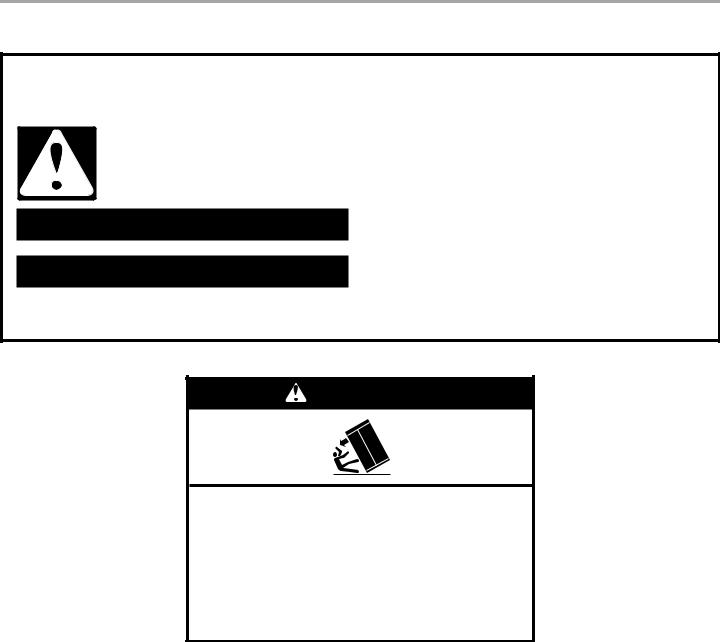
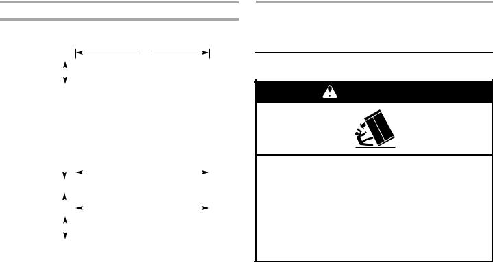
WARNING
Refrigerator is top |
easily when not |
completely installed. |
|
Keep doors taped closed until refrigerator is completely installed.
Use two or more people to move and install refrigerator.
Failure to do so can result in death or serious injury.
3
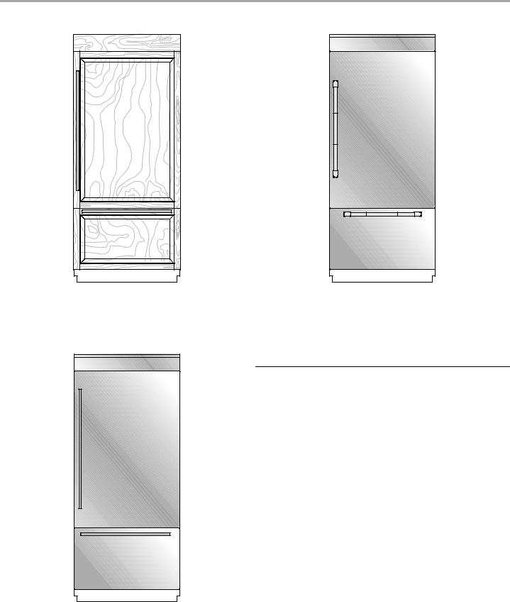
36" SINGLE-DOOR MODELS
Custom-Made Panel Design
Features custom-made panels and custom hardware provided by the cabinetmaker for a seamless appearance designed to blend with existing kitchen cabinetry.
Base Model Numbers: JB36NXFXLE, JB36NXFXRE
Pro-Style® Stainless Design
Features stainless steel wrapped doors and Pro-Style® handles with diamond-etched grip.
Base Model Numbers: JB36NXFXLE, JB36NXFXRE
Kit Model Number: JPK36BNXEPS
Accessories
All factory parts are available through your Jenn-Air dealer or by calling Jenn-Air at 1-800-JENNAIR (1-800-536-6247). In Canada, call 1-800-807-6777.
Door Handle Kits
For custom wood overlay panels only, handle kits can be ordered. Follow the kit instructions for installation.
IMPORTANT: These handle kits are not intended for use with stainless steel door panel kits.
Pro-Style® Stainless Steel—BM—W10250641
Euro-Style Stainless Steel—BM—W10250638
Armoire-Style Door Panel Kit
Refer to the installation instructions that come with the Armoire kit, for custom wood overlay panel dimensions and installation details.
36" Model (Black)—W10663562
Euro-Style Stainless Design
Features stainless steel wrapped doors and new Euro-style handles designed to compliment the Jenn-Air® Euro kitchen suite or enhance any kitchen decor.
Base Model Numbers: JB36NXFXLE, JB36NXFXRE
Kit Model Number: JPK36BNXESS
4
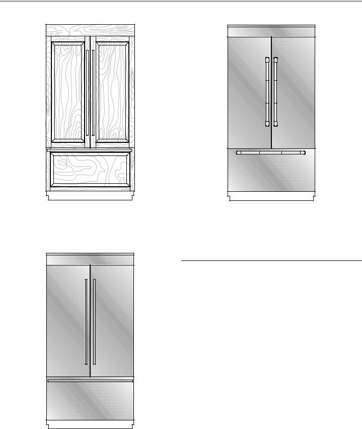
36" FRENCH DOOR MODELS
Custom-Made Panel Design
Features custom-made panels and custom hardware provided by the cabinetmaker for a seamless appearance designed to blend with existing kitchen cabinetry.
Base Model Number: JF36NXFXDE
Pro-Style® Stainless Design
Features stainless steel wrapped doors and Pro-Style® handles with diamond-etched grip.
Base Model Number: JF36NXFXDE
Kit Model Number: JPK36FNXEPS
Accessories
All factory parts are available through your Jenn-Air dealer or by calling Jenn-Air at 1-800-JENNAIR (1-800-536-6247). In Canada, call 1-800-807-6777.
Door Handle Kits
For custom wood overlay panels only, handle kits can be ordered. Follow the kit instructions for installation.
IMPORTANT: These handle kits are not intended for use with stainless steel door panel kits.
Pro-Style® Stainless Steel FDBM—W10745429
Euro-Style Stainless Steel FDBM—W10745430
Armoire-Style Door Panel Kit
Follow the kit instructions for installation.
36" Model (Black)—W10663562
Euro-Style Stainless Design
Features stainless steel wrapped doors and new Euro-style handles designed to compliment the Jenn-Air® Euro kitchen suite or enhance any kitchen decor.
Base Model Number: JF36NXFXDE
Kit Model Number: JPK36FNXESS
5

42" FRENCH DOOR MODELS
Custom-Made Panel Design
Features custom-made panels and custom hardware provided by the cabinetmaker for a seamless appearance designed to blend with existing kitchen cabinetry.
Base Model Number: JF42NXFXDE
Pro-Style® Stainless Design
Features stainless steel wrapped doors and Pro-Style® handles with diamond-etched grip.
Base Model Number: JF42NXFXDE
Kit Model Number: JPK42FNXEPS
Accessories
All factory parts are available through your Jenn-Air dealer or by calling Jenn-Air at 1-800-JENNAIR (1-800-536-6247). In Canada, call 1-800-807-6777.
Door Handle Kits
For custom wood overlay panels only, handle kits can be ordered. Follow the kit instructions for installation.
IMPORTANT: These handle kits are not intended for use with stainless steel door panel kits.
Pro-Style® Stainless Steel FDBM—W10250642
Euro-Style Stainless Steel FDBM—W10250639
Armoire-Style Door Panel Kit
Follow the kit instructions for installation.
42" Model (Black)—W10663564
Euro-Style Stainless Design
Features stainless steel wrapped doors and new Euro-style handles designed to compliment the Jenn-Air® Euro kitchen suite or enhance any kitchen decor.
Base Model Number: JF42NXFXDE
Kit Model Number: JPK42FNXESS
6
INSTALLATION REQUIREMENTS
Tools and Parts
IMPORTANT:
■Installer: Leave Installation Instructions with the homeowner.
■Homeowner: Keep Installation Instructions for future reference. Save these Installation Instructions for the local electrical inspector’s use.
Tools Needed:
Gather the required tools and parts before starting installation. Read and follow the instructions provided with any tools listed here.
■ |
Cordless drill |
■ |
³⁄" and ¹⁄" open-end wrenches |
■ |
Drill bits |
■ |
⁄" and ³⁄" hex key |
■ |
Adjustable wrenches (2) |
■ |
¹⁄" and ⁄" socket drivers |
■ |
Phillips screwdriver |
■ |
Tape measure |
■ |
Small level |
■ |
Utility knife |
■ |
³⁄" hex key |
■ |
Tape (painters) |
|
(panel kits only) |
■ |
Appliance dolly |
|
|
■¹¹⁄" nut driver
Parts Needed:
■#8 x 3" (7.6 cm) wood screws (longer screws may be needed) (6)
■2" x 4" x 32" (5 cm x 10 cm x 81 cm) wood boards (2)
■Custom wood overlay panels—consult a qualified cabinetmaker or carpenter to make the custom wood panels. See “Custom Wood Overlay Panels” for more information.
OR
Panel kit—See “36" Models or 42" French Door Models” for panel kit information.
■Flexible, codes-approved water supply tubing, a ferrule, a union and a ¹⁄" (6.35 mm) compression fitting.
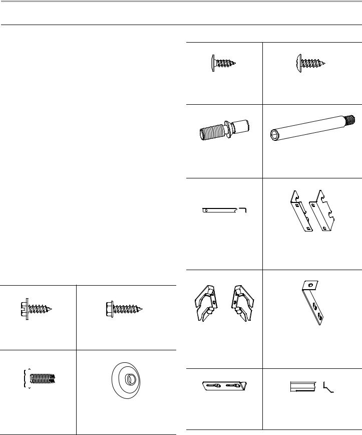
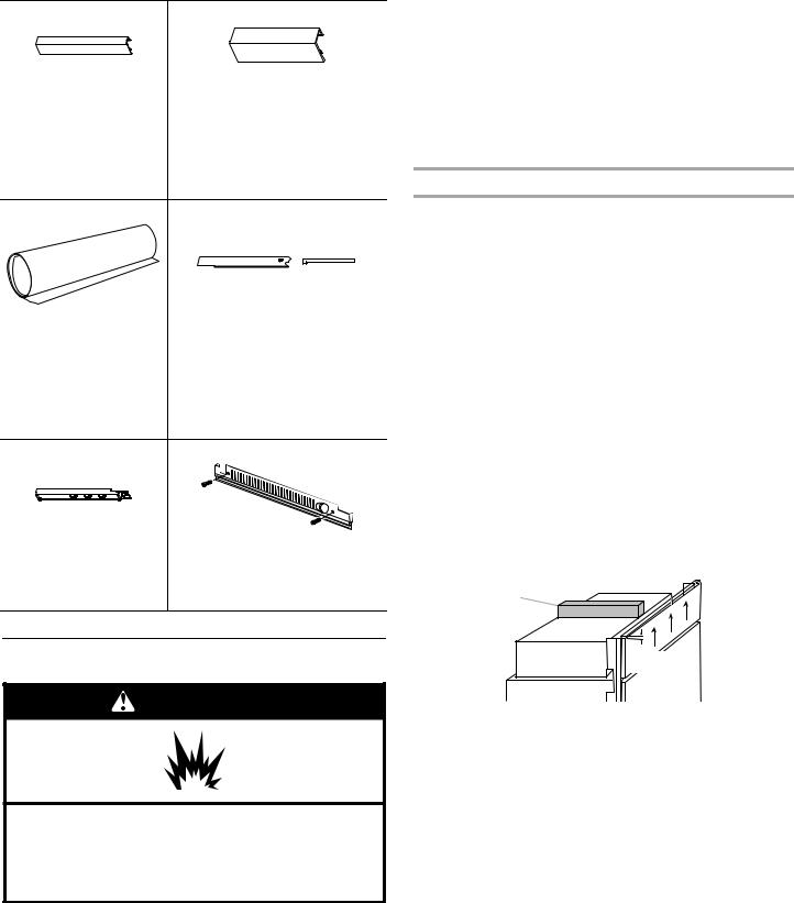
Parts Provided:
Slotted Hex-head Screw |
Hex-head Pointed Screw |
|||
W10141645 (21) |
W10141189 (8) |
|||
|
|
|
|
|
|
|
|
|
|
|
|
|
|
|
|
|
|
|
|
|
|
|
|
|
Hex-head Blunt Screw |
Shoulder Washer (use with hex-head |
|
pointed screw) |
W10142233 (4) |
W10471946 (4) |
Phillips-head Flat Screw |
Round-head Screw |
8281252 (28) |
1163283 (24) |
Door Adjustment Pin |
Door Stop Pin |
(preinstalled) |
|
W10234194 (2) |
W10234202 (2) |
Drawer Panel Bracket |
Standard Integrated Grille Bracket |
W10606815 (2) |
W10182743—Left (1) |
|
W10182741—Right (1) |
Fully Integrated Grille |
Filler Board “L” Bracket |
Bracket |
|
W10260890—Left (1) |
W10234199 (2) |
W10260891—Right (1) |
|
Panel Top Bracket |
Top Grille Lower Trim |
W10667450 (2) |
W10634858—36" BM (1) |
|
W10606812—42" BM, SxS (1) |
|
7 |
RC Hinge Cover Trim |
FC Hinge Cover Trim |
|
W10648975—36" BM |
W10611107—36" BM (Left) |
|
(Right) |
W10582015—36" FDBM (Left) |
|
W10564251—36" FDBM |
||
W10606808—42" FDBM (Left) |
||
(Right) |
||
|
||
W10606804—42" FDBM |
|
|
(Right) |
|
|
Panel Templates |
Handle Side Door Trim |
|
W10222281—SxS |
W10611106—BM (Left) |
|
W10488115—36" BM |
W10648977—BM (Right) |
|
W10704869—36" FDBM |
W10606802—FDBM (Right) |
|
W10488118—42" FDBM |
W10606806—FDBM (Left) |
|
W10489178—Grille |
|
|
Installation Block |
Grille—Bottom / Skirt—Grille |
|
W10234156 |
W10189198 / W10188549—42" BM |
|
|
W10189196 / W10188547—36" BM |
Location Requirements
WARNING
Explosion Hazard
Keep flammable materials and vapors, such as gasoline, away from refrigerator.
Failure to do so can result in death, explosion, or fire.
IMPORTANT:
■Observe all governing codes and ordinances.
■It is recommended that you do not install the refrigerator near an oven, radiator, or other heat source.
■Do not install in a location where the temperature will fall below 55°F (13°C).
■Floor must support the refrigerator weight, more than 600 lbs (272 kg), door panels and contents of the refrigerator. Flooring under refrigerator must be at same level as the room. Face of cabinetry must be plumb.
■Ceiling height must allow for side tipping radius. See “Tipping Radius.”
■Location should permit door to open fully. See “Door Swing Dimensions.”
■Location must permit top grille removal. See “Opening Dimensions.”
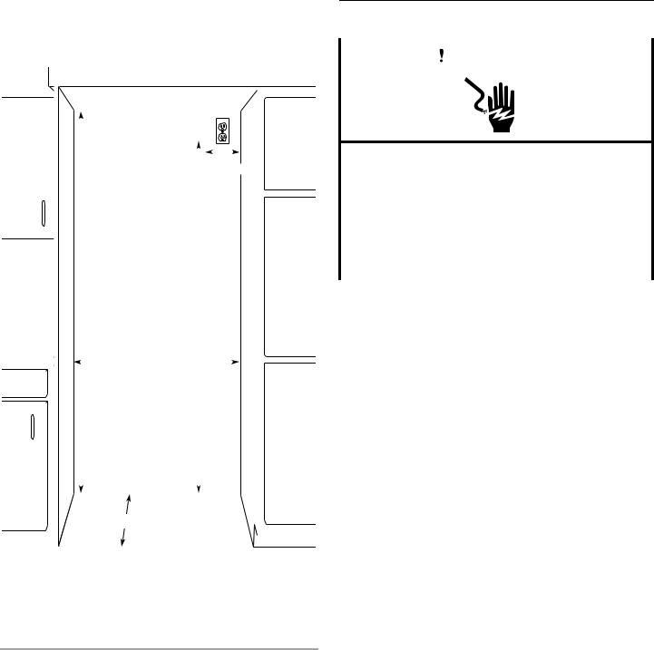
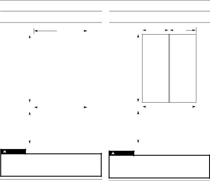
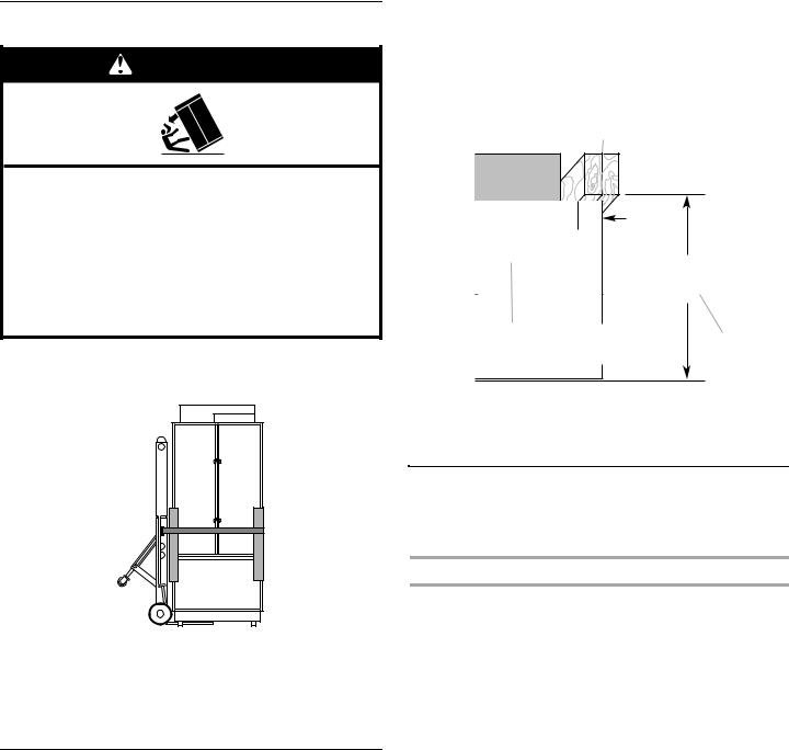
Opening Dimensions
IMPORTANT:
■The width of the opening (Width A), from side to side, must be as specified for your model, for at least 2" (5.08 cm) back from the face of the cabinet.
NOTE: If your opening does not meet this requirement, you will need to make modifications.
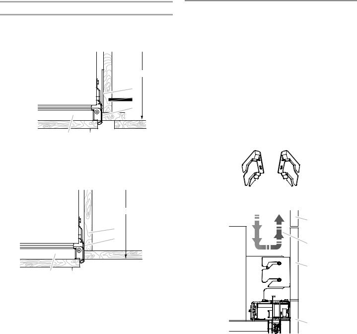
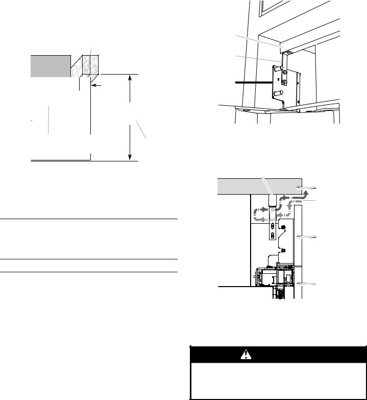
■A solid soffit or wall cabinet must be installed 84" (213.4 cm) above the floor. If the solid soffit is higher than 84" (213.4 cm) or one is not available, then the refrigerator must be braced.
If anti-tip boards are needed, they must be attached to the rear wall studs so that there is 84" (213.4 cm) from the bottom of the anti-tip board to the floor. See “Install Anti-Tip Boards” for more information.
NOTES:
■A clearance of ¹⁄" (1.3 cm) must be maintained above the top grille so that the top grille can be removed.
■Do not remove the foam gasket from the top of the compressor cover unless removal is necessary to fit the unit under a soffit. Removal of the gasket will cause loss in cooling efficiency.
■If installing under a solid soffit, after installation raise the leveling legs so that the gasket is pressed snugly against the soffit.
A
B 
¹⁄"
(1.3 cm)
A.Gasket
B.Compressor cover
■For a fully integrated installation, a minimum of 6" (15.24 cm) of open space above the refrigerator is required. See “Fully Integrated Installation.” Anti-tip boards are required. See “Install Anti-Tip Boards” for more information.
■A grounded 3 prong electrical outlet should be located within a specified number of inches from the right-hand side cabinets or end panel. See the chart following the graphic for the number of inches required for your model. For more information, see “Electrical Requirements.”
8
■The water shutoff should be located in the base cabinet on
either side of the refrigerator or some other easily accessible |
Electrical Requirements |
|
|
area. If the water shutoff valve is not in the cabinets, the |
|
||
plumbing for the water line can come through the floor. See |
|
|
|
“Water Supply Requirements” for more information. |
WARNING |
|
|
|
|
|
|
|
|
|
|
|
|
|
|
|
|
|
|
|
|
|
|
|
|
|
|
|
|
|
|
|
|
|
|
|
|
|
|
|
|
|
Electrical Shock Hazard |
|
|
|
|
|
|
|
|
|
|
|
|
|
|
|
|
|
|
|
|
|
|
|
|
|
|
|
|
|
|
|
|
|
|
|
|
|
|
|
|
|
|
|
|
|
|
|
|
|
|
|
|
|
|
|
|
|
|
|
|
|
|
|
|
|
|
|
|
|
|
|
|
|
|
|
|
|
|
|
|
|
|
|
|
|
|
|
|
|
|
|
|
|
|
|
|
|
|
|
|
|
|
|
|
|
|
|
|
|
|
|
|
|
|
|
|
|
|
|
|
|
|
|
|
|
|
|
|
|
|
|
|
|
|
|
|
|
|
|
|
|
|
|
|
|
|
|
|
|
|
|
|
|
|
|
|
|
|
|
|
|
|
|
|
|
|
|
|
|
|
|
|
|
|
|
|
|
|
|
|
|
|
|
|
|
|
|
|
|
|
|
|
|
|
|
|
|
|
|
|
|
|
|
|
|
|
|
|
|
|
|
|
|
B |
|
|
|
|||||||
|
|
|
|
|
|
|
|
|
|
|
|
|
|
|
|
|
|
|
|
|
|
|
|
|
|
|
|||||
|
|
|
|
|
|
|
|
|
|
|
|
|
|
|
|
|
|
|
Dimension |
|
|
|
|
|
|
Plug into a grounded 3 prong outlet. |
|||||
|
|
|
|
|
|
|
|
|
|
|
|
|
|
|
|
|
|
|
|
|
|
|
|
|
|
|
|
|
|||
|
|
|
|
|
|
|
|
|
|
|
|
|
|
|
|
|
|
|
|
|
|
|
|
|
|
|
|
|
|
|
Do not remove ground prong. |
|
|
|
|
|
|
|
|
|
|
|
|
|
|
|
|
|
|
|
|
|
|
|
|
|
|
|
|
|
|
|
|
|
|
|
|
|
|
|
|
|
|
|
|
|
|
|
|
|
|
|
|
|
|
|
|
|
|
|
|
|
|||
|
|
|
|
|
|
|
|
|
|
|
|
|
|
|
|
|
|
|
|
|
|
|
|
|
|
|
|
|
|
|
Do not use an adapter. |
|
|
|
|
|
|
|
|
|
|
|
|
|
|
|
|
|
|
|
|
|
|
|
|
|
|
|
|
|
|||
|
|
|
|
|
|
|
|
|
|
|
|
|
|
|
|
|
|
|
|
|
|
|
|
|
|
|
|
|
|
|
Do not use an extension cord. |
|
|
|
|
|
|
|
|
|
|
84" (213.4 cm) |
|
|
|
|
|
|
|
|
|
|
|
|
|
|
|
|
|||||
|
|
|
|
|
|
|
|
|
|
|
|
|
|
|
|
|
|
|
|
|
|
|
|
|
|||||||
|
|
|
|
|
|
|
|
|
to bottom of solid soffit |
|
|
|
|
|
|
|
|
|
|
|
|
Failure to follow these instructions can result in death, |
|||||||||
|
|
|
|
|
|
|
|
|
|
|
|
|
|
|
|
|
|
|
|
|
|
|
|
|
|
|
|
|
|
|
fire, or electrical shock. |
|
|
|
|
|
|
|
|
|
|
|
|
|
|
|
|
|
|
|
|
|
|
|
|
|
|
|
|
|
|
|
|
|
|
|
|
|
|
|
|
|
|
|
|
|
|
|
|
|
|
|
|
|
|
|
|
|
|
|
|
|
|
Before you move your refrigerator into its final location, it is |
|
|
|
|
|
|
|
|
|
|
|
|
|
|
|
|
77" |
|
|
|
|
|
|
|
|
|
important to make sure you have the proper electrical connection. |
||||||
|
|
|
|
|
|
|
|
|
|
|
|
|
|
|
|
|
|
|
|
|
|
|
|
|
|
|
|||||
|
|
|
|
|
|
|
|
|
|
|
|
|
|
|
|
|
|
(196 cm) |
|
|
|
|
|
|
|
|
Recommended Grounding Method |
||||
|
|
|
|
|
|
|
|
|
|
|
|
|
|
|
|
|
|
|
|
|
|
|
|
|
|
|
|
|
|
||
|
|
|
|
|
|
|
|
|
|
|
|
|
|
|
|
|
|
|
|
|
|
|
|
|
|
|
|
|
|
A 115 volt, 60 Hz., AC only, 15or 20-amp fused, grounded |
|
|
|
|
|
|
|
|
|
|
|
|
|
|
|
A |
|
|
|
|
|
|
|
|
|
|
|
|
|
|
electrical supply is required. It is recommended that a separate |
||
|
|
|
|
|
|
|
|
|
|
|
|
|
|
|
|
|
|
|
|
|
|
|
|
|
|
|
|||||
|
|
|
|
|
|
|
|
|
|
|
|
|
|
|
|
|
|
|
|
|
|
|
circuit serving only your refrigerator be provided. Use an outlet |
||||||||
|
|
|
|
|
|
|
|
|
|
|
|
|
|
|
|
|
|
|
|
|
|
|
|||||||||
|
|
|
|
|
|
|
|
|
|
|
|
|
|
Width |
|
|
|
|
|
|
|
|
|
|
|
|
|
||||
|
|
|
|
|
|
|
|
|
|
|
|
|
|
|
|
|
|
|
|
|
|
|
|
|
|
that cannot be turned off by a switch. Do not use an |
|||||
|
|
|
|
|
|
|
|
|
|
|
|
(see chart following) |
|
|
|
|
|
|
|
|
|
|
|
extension cord. |
|||||||
|
|
|
|
|
|
|
|
|
|
|
|
|
|
|
|
|
|
|
|
|
|
|
|
|
|
|
|
|
|
||
|
|
|
|
|
|
|
|
|
|
|
|
|
|
|
|
|
|
|
|
|
|
|
|
|
|
|
|
|
|
IMPORTANT: If this product is connected to a GFCI (Ground Fault |
|
|
|
|
|
|
|
|
|
|
|
|
|
|
|
|
|
|
|
|
|
|
|
|
|
|
|
|
|
|
|
||
|
|
|
|
|
|
|
|
|
|
|
|
|
|
|
|
|
|
|
|
|
|
|
|
|
|
|
|
|
|
||
|
|
|
|
|
|
|
|
|
|
|
|
|
|
|
|
|
|
|
|
|
|
|
|
|
|
|
|
|
|
Circuit Interrupter) protected outlet, nuisance tripping of the |
|
|
|
|
|
|
|
|
|
|
|
|
|
|
|
|
|
|
|
|
|
|
|
|
|
|
|
|
|
|
|
power supply may occur, resulting in loss of cooling. Food quality |
|
|
|
|
|
|
|
|
|
|
|
|
|
|
|
|
|
|
|
|
|
|
|
|
|
|
|
|
|
|
|
and flavor may be affected. If nuisance tripping has occurred, and |
|
|
|
|
|
|
|
|
|
|
|
|
|
|
|
|
|
|
|
|
|
|
|
|
|
|
|
|
|
|
|
if the condition of the food appears poor, dispose of it. |
|
|
|
|
|
|
|
|
|
|
|
|
|
|
|
|
|
|
|
|
|
|
|
|
|
|
|
|
|
|
|
NOTE: Before performing any type of installation or cleaning, |
|
|
|
|
|
|
|
|
|
|
|
|
|
|
|
|
|
|
|
|
|
|
|
|
|
|
|
|
|
|
|
remove the top grille and turn the master power switch to OFF or |
|
|
|
|
|
|
|
|
|
|
|
|
|
|
|
|
|
|
|
|
|
|
|
|
|
|
|
|
|
|
|
disconnect power at the circuit breaker box. |
|
|
|
|
|
|
|
|
|
|
|
|
|
|
|
|
|
|
|
|
|
|
|
|
|
|
|
|
|
|
|
When you are finished, turn ON the master power switch or |
|
|
|
|
|
|
|
|
|
|
|
|
|
|
|
|
|
|
|
|
|
|
|
|
|
|
|
|
|
|
|||
|
|
|
|
|
|
|
|
|
|
|
|
|
|
|
|
|
|
|
|
|
|
|
|
|
|
|
|
|
|
reconnect power at the circuit breaker box. Then reset the control |
|
|
|
|
|
|
|
|
|
|
|
|
|
C |
Depth |
|
|
|
|
to the desired setting. |
|||||||||||||
|
|
|
|
|
|
|
|
|
|
|
|
|
|
|
|||||||||||||||||
|
|
|
|
|
|
|
|
|
|
|
|
|
|
|
|
|
|
||||||||||||||
|
|
|
|
|
|
|
|
|
|
|
|
|
|
|
|
|
|
|
|
|
|
|
|
|
|
|
|
|
|
|
|
|
|
|
|
|
|
|
|
|
|
|
|
|
|
|
|
|
|
|
|
|
|
|
|
|
|
|
|
|
|
|
|
|
|
|
|
|
|
|
|
|
|
|
|
|
|
|
|
|
|
|
|
|
|
|
|
|
|
|
|
|
|
|
|
|
|
|
|
|
|
|
|
|
|
|
|
|
|
|
|
|
|
|
|
|
|
|
|
|
|
|
|
|
|
|
|
|
Width A |
Dimension B |
|
Model |
(as shown above) |
(as shown above) |
|
|
|
|
|
36 |
36" |
(91.4 cm) |
4" (10.2 cm) |
42 |
42" |
(106.7 cm) |
7¹⁄" (19.1 cm) |
Installation Type |
Depth C (as shown |
|
above) |
|
|
Standard Flush |
25" (63.5 cm) minimum |
(new installation) |
|
|
|
Retrofit Installations |
24" (60.9 cm) minimum |
|
|
9
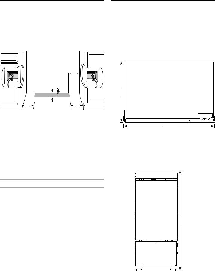
Water Supply Requirements |
Product Dimensions |
|
IMPORTANT: |
IMPORTANT: |
|
■ All installations must meet local plumbing code requirements. |
■ The depth from the front face of the doors to the back of the |
|
■ There is not enough clearance to achieve a flush installation if |
refrigerator cabinet is 24" (60.96 cm) without panels. |
|
a water shutoff valve is located in the wall behind the |
■ The power cord is 84" (213 cm) long. |
|
refrigerator. |
■ The water supply connection is made at the bottom front of |
|
■ The water shutoff should be located in the base cabinet on |
||
the refrigerator. |
||
either side of the refrigerator or some other easily accessible |
|
|
area. The water supply line, however, must come up through |
36" Single Door and 36" French Door Bottom Mount |
|
the floor in the gray shaded area shown. |
||
|
|
|
|
Top View |
|
|
6" |
|
|
(15.2 cm) |
|
|
24" |
|
|
(61.0 cm) |
6" |
1" |
6" |
(2.54 cm) |
||
2 cm) |
|
(15.2 cm) |
■A ½" (12.7 mm) hole for plumbing should be drilled on the floor at least 6" (15.2 cm) from the rightor left-hand side cabinet and should be no more than 1" (2.54 cm) away from the back wall. See “Connect the Water Supply.”
■The water supply connection is made at the front of the refrigerator.
■If additional tubing is needed, use copper tubing and check for leaks. Install the copper tubing only in areas where the household temperatures will remain above freezing.
■Do not use a piercing-type or ³⁄ " (4.76 mm) saddle valve which reduces water flow and also clogs more easily.
NOTE: Your refrigerator dealer has a kit available with a ¹⁄ " (6.35 mm) saddle-type shutoff valve, a union, and copper tubing. Before purchasing, make sure a saddle-type valve complies with your local plumbing codes.
Water Pressure
A cold water supply with water pressure between 30 and 120 psi (207 and 827 kPa) is required to operate the water dispenser and ice maker. If you have questions about your water pressure, call a licensed, qualified plumber.
Reverse Osmosis Water Supply
IMPORTANT: The pressure of the water supply coming out of a reverse osmosis system going to the water inlet valve of the refrigerator needs to be between 30 and 120 psi (207 and
827 kPa).
If a reverse osmosis water filtration system is connected to your cold water supply, the water pressure to the reverse osmosis system needs to be a minimum of 40 to 60 psi (276 to 414 kPa).
If the water pressure to the reverse osmosis system is less than 40 to 60 psi (276 to 414 kPa):
■Check to see whether the sediment filter in the reverse osmosis system is blocked. Replace the filter if necessary.
■Allow the storage tank on the reverse osmosis system to refill after heavy usage.
■If your refrigerator has a water filter, it may further reduce the water pressure when used in conjunction with a reverse osmosis system. Remove the water filter cartridge.
If you have questions about your water pressure, call a licensed, qualified plumber.
35³⁄ " |
(90.8 cm)
Front View
■Width dimensions were measured from hinge edge to clip edge.
■When leveling legs are fully extended to 1¹⁄ " (3.2 cm) below rollers, add 1¹⁄ " (3.2 cm) to the height dimension.
35³⁄ "
 (90.8 cm)

83¹⁄"
(211.1 cm)
10
42" French Door Bottom Mount
Top View
24" (61.0 cm)
41³⁄ "
(106.1 cm)
Front View
■Width dimensions were measured from hinge edge to hinge edge.
■When leveling legs are fully extended to 1¹⁄ " (3.2 cm) below rollers, add 1¹⁄ " (3.2 cm) to the height dimension.
41³⁄ "
(106.1 cm)
83¹⁄"
(211.1 cm)
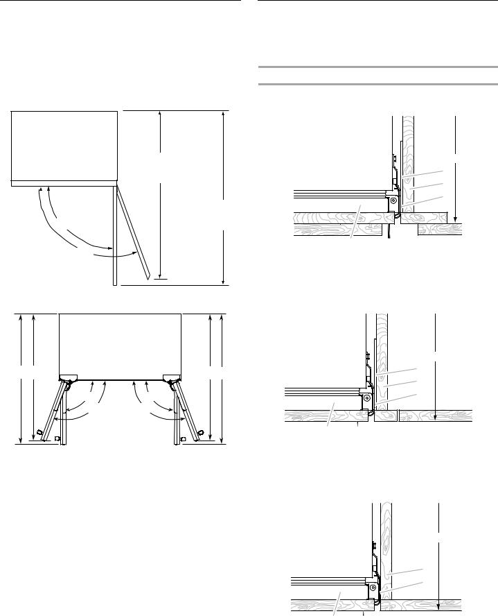
Tipping Radius
Be sure there is adequate ceiling height to stand the refrigerator upright when it is moved into place.
■The dolly wheel height must be added to the tipping radius when a dolly is used.
NOTE: Tip on side only.
Side Tipping Radius—36" (91.4 cm) Models
A
A. 88⁄" (225.7 cm)
Side Tipping Radius—42" (106.7 cm) Models
A
A. 91³⁄" (232.1 cm)
11
Door Swing Dimensions
■The location must permit both doors to open to a minimum of 90°.
■Allow 4¹⁄ " (11.4 cm) minimum space between the side of the refrigerator and a corner wall.
NOTE: More clearance may be required if you are using custom wood overlay panels, custom handles or extended handles.
36" (91.4 cm) Single Door Models
B
A
90º
110º
36" (91.4 cm) and 42" (106.6 cm) French Door Models
A |
B |
C D |
|
90˚ |
90˚ |
|
110˚ |
110˚ |
|
Model |
A |
B |
C |
D |
|
36 |
58³⁄ " |
56 ⁄ " |
56 ⁄ " |
58³⁄ " |
|
|
(149.2 cm) |
(143.8 cm) |
(143.8 cm) |
(149.2 cm) |
|
|
|
|
|
|
|
36 FD |
41" |
39³⁄ " |
39³⁄ " |
41" |
|
|
(104 cm) |
(101 cm) |
(101 cm) |
(104 cm) |
|
|
|
|
|
|
|
42 FD |
44" |
42³⁄ " |
42³⁄ " |
44" |
|
|
(111.8 cm) |
(108.6 cm) |
(108.6 cm) |
(111.8 cm) |
|
|
|
|
|
|
Cabinet and Panel
Installation Options
NOTE: Graphics shown below illustrate installation configuration options given the specified cabinet depths. All possible configurations are not shown.
Cabinet Depth—25" (63.5 cm)
Framed Cabinetry
Top View
A
A.Refrigerator door
B.Door panel
C.Side trim
F |
E |
D |
C |
B
D.Adjacent cabinet E. Flush return filler F. 25" (63.5 cm)
Inset
Top View
F |
E |
D |
C |
A |
B |
|
A. Refrigerator door |
D. Adjacent cabinet |
|
B. Door panel |
|
E. Flush return filler |
C. Side trim |
|
F. 25" (63.5 cm) |
Frameless Cabinetry
Top View
|
|
E |
|
|
D |
|
|
C |
A |
B |
|
A. Refrigerator door |
D. Adjacent cabinet |
|
B. Door panel |
|
E. 25" (63.5 cm) |
C. Side trim |
|
|
12
Cabinet Depth—24" (60.9 cm)
NOTE: A flush installation is not possible with a 24" (60.9 cm) deep opening.
Framed Cabinetry
Top View
F
|
E |
|
D |
|
C |
A |
B |
A. Refrigerator door |
D. Adjacent cabinet |
B. Door panel |
E. Flush return filler |
C. Side trim |
F. 24" (60.9 cm) |
Frameless Cabinetry
Top View
E |
D |
C |
A |
B |
|
A. Refrigerator door |
D. Adjacent cabinet |
|
B. Door panel |
|
E. 24" (60.9 cm) |
C. Side trim |
|
|
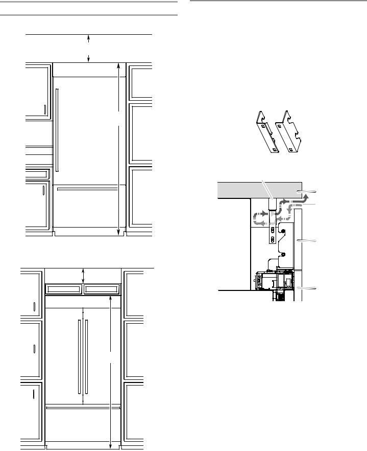
Fully Integrated Grille Installation
Requirements
The refrigerator can be installed fully integrated if the adjacent cabinetry meets the airflow venting requirements critical to refrigerator performance. A Fully Integrated Grille installation has no visible air gap because the grille extends upward to the soffit or upper cabinet.
IMPORTANT:
■A Fully Integrated Grille installation requires a minimum of 6" (15.24 cm) of open space above the refrigerator. This space must not be blocked in any way, including by soffits.
■A Fully Integrated Grille installation can be achieved with either a 24" (60.9 cm) or 25" (63.5 cm) deep opening.
■A full height grille is used to achieve a Fully Integrated Grille installation. Use the integrated grille bracket (provided with refrigerator) to attach the full height grille.
NOTE: A top grille vent is not required with a full height grille.
Integrated Grille Bracket
Fully Integrated Grille Installation—Side View
A |
B |
C |
D |
A. False front (optional) |
C. Full height grille* |
B. Airflow |
D. Door panel* |
*C and D are one piece in the Full-height Door Installation option.
13
Fully Integrated Grille Installation Options
Option 1—Open to Ceiling
6" (15.24 cm) min.
84" |
(213.4 cm) |
Option 2—False Front (cabinet face only)
6" (15.24 cm) |
min. |
84" |
(213.4 cm) |
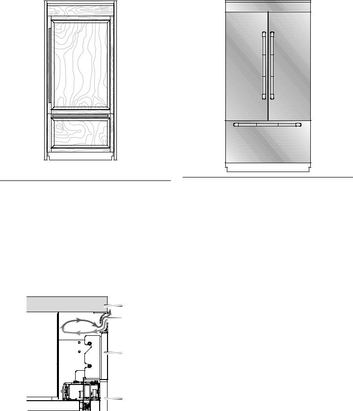
Standard Integrated Grille
Installation Requirements
IMPORTANT:
■A Standard Integrated Grille installation can be achieved with either a 24" (60.9 cm) or 25" (63.5 cm) deep opening.
■A standard grille is used to achieve a Standard Integrated Grille installation. Use the standard grille bracket (provided with refrigerator) to attach the standard grille.
■The grille panel height, shown in the “Standard Integrated Grille Installation—Side View” graphic, allows for an air gap critical to refrigerator performance.
Standard Grille Bracket
Standard Integrated Grille Installation—Side View
A |
B |
C |
D |
E |
A. Top grille filler |
D. Grille panel |
B. Soffit |
E. Door panel |
C. Airflow |
|
14
Standard Integrated Grille Installation—Full Product View |
Panel Kit Installation—Full Product View |
 C
C
C. Airflow
Stainless Steel Panel Kit
Installation Requirements
See the “36" Single Door Models” or the “36" or 42" French Door Models” section to see the panel kit options available for your model.
IMPORTANT:
■A panel kit installation can be achieved with either a 24" (60.9 cm) or 25" (63.5 cm) deep opening.
■Refer to the instructions provided with the Stainless Steel Door Panel Kit to install the door panels and standard grille.
■The grille panel height, shown in the “Panel Kit Installation— Side View” graphic, allows for an air gap critical to refrigerator performance.
Panel Kit Installation—Side View
|
A |
|
B |
|
C |
|
D |
A. Soffit |
C. Grille panel |
B. Airflow |
D. Door panel |
Custom Wood Overlay Panel
Requirements
Custom wood overlay panels allow you to blend the exterior of your refrigerator into the overall kitchen décor and to use custom handles for additional design flexibility.
In some cases, your cabinet manufacturer may choose to work with one panel routed for the different dimensions. Follow these panel dimension and placement instructions to be sure that the custom wood overlay panels will fit properly.
IMPORTANT:
■For 36" (91.4 cm) Single Door models, the refrigerator door wood overlay panel cannot exceed 60 lbs (27.2 kg) and the freezer drawer overlay panel cannot exceed 25 lbs (11.3 kg).
■For 36" French Door models, the refrigerator door wood overlay panel cannot exceed 38 lbs (17.2 kg) and the freezer drawer overly panel cannot exceed 25 lbs (11.3 kg).
■For 42" (106.7 cm) French Door models, the refrigerator door wood overlay panel cannot exceed 38 lbs (17.2 kg) and the freezer drawer overlay panel cannot exceed 30 lbs (13.6 kg).
■The weight of the top grille wood overlay panel cannot exceed 7 lbs (3.2 kg) for both models.
■The required thickness for all panels is ³⁄" (1.91 cm).
■This installation does not require filler or backer panels.
15
Custom Wood Overlay Panel Dimensions
36" (91.4 cm) Single Door Model—Door and Drawer Panels
36" (91.4 cm) and 42" (106.7 cm) French Door Models—Door and Drawer Panels
|
|
|
|
|
|
|
|
|
|
|
|
|
|
|
|
|
|
|
|
|
|
|
A |
|
|
|
|
|
A |
A |
|
|
|
|
|
|
|
|
|
|
|
|
||
|
|
|
|
|
|
|
|
|
||||||
|
||||||||||||||
|
|
|
|
|
|
|
|
|
|
|
|
|
|
|
|
|
|
|
|
|
|
|
|
|
|
|
REFRIGERATOR |
REFRIGERATOR |
|
|
|
|
|
|
|
|
|
|
|
|
||
* 52 |
³⁄ " |
|
REFRIGERATOR DOOR PANEL |
* 52 |
³⁄ " |
|
DOOR PANEL |
DOOR PANEL |
|||||
(133.03 cm) |
|
|
(133.03 cm) |
|
Maximum Weight: |
Maximum Weight: |
|||||||
|
Maximum Weight: 60 lbs (27.2 kg) |
|
|||||||||||
|
|
|
|
|
|
|
|
|
|
|
|
38 lbs (17.2 kg) |
38 lbs (17.2 kg) |
|
|
|
|
|
|
|
|
|
|
|
|
|
|
|
|
|
|
|
|
|
|
|
|
|
|
|
|
|
|
|
|
|
|
|
|
|
|
|
|
|
|
|
|
|
|
|
|
|
|
|
|
|
|
|
|
|
|
|
|
B |
|
|
|
|
|
|
|
|
|
|
B |
|
|
|
|
|
|
|
|
|
|
|
|
|
|
|
|
|
|
|
|
|
|
|
|
|
|
|
|
|
||||
|
|
|
|
|
|
|
|
|
|
|
|
|
|
|||||||
|
|
|
|
|
|
|
|
|
|
|
|
|
|
|
|
|
|
|
|
|
|
|
|
|
|
|
|
|
|
|
|
|
|
|
|
||||||
|
|
|
|
|
|
|
|
|
|
|
|
|
|
|
||||||
20 |
¹⁄ " |
|
|
FREEZER DRAWER PANEL |
20 |
¹⁄ " |
|
|
FREEZER DRAWER PANEL |
|||||||||||
(52.07 cm) |
|
|
Maximum Weight: 25 lbs (11.34 kg) |
(52.07 cm) |
|
|
Maximum Weight: 30 lbs (13.6 kg) |
|||||||||||||
|
|
|
|
|
|
|
|
|
|
|
|
|
|
|
|
|
|
|
|
|
|
|
|
|
|
|
|
|
|
|
|
|
|
|
|
|
|
|
|
|
|
|
|
|
|
|
|
|
|
|
|
|
|
|
|
|
|
|
|
|
|
|
 CAUTION
Pinch Hazard
Installation of door panels with less than a ³⁄ " (0.95 cm) gap between the door panel and the adjacent cabinet increases the risk of potential pinching.
Model |
36" Single Door Bottom Mount |
|
Reveal |
³⁄ " |
¹⁄ " |
A |
35¹⁄ " (89.54 cm) |
35³⁄ " (90.81 cm) |
B |
35¹⁄ " (89.54 cm) |
35³⁄ " (90.81 cm) |
|
|
|
*For Fully-integrated grille or Standard grille installations.
 CAUTION
Pinch Hazard
Installation of door panels with less than a ³⁄ " (0.95 cm) gap between the door panel and the adjacent cabinet increases the risk of potential pinching.
Model |
36" French Door Bottom Mount |
|
Reveal |
³⁄ " |
¹⁄ " |
A |
17 ⁄ " (44.6 cm) |
17¹³⁄ " (45.2 cm) |
|
|
|
B |
35¹⁄ " (89.5 cm) |
35³⁄ " (90.8 cm) |
|
|
|
|
|
|
Model |
42" French Door Bottom Mount |
|
|
|
|
Reveal |
³⁄ " |
¹⁄ " |
A |
20 ⁄ " (52.23 cm) |
20¹³⁄ " (52.86 cm) |
|
|
|
B |
41¹⁄ " (104.78 cm) |
41³⁄ " (106.05 cm) |
|
|
|
*For Fully-integrated grille or Standard grille installations.
16
Grille Panel
Fully-Integrated Installation—Full Height Grille—Open
Soffit
C
|
|
|
|
|
|
6⁄" |
|
|
Top Grille Panel |
|
|
|
|
||||
(16.83 cm) |
|
|
|
||
|
|
|
|||
|
|
|
|
|
|
|
|
|
|
|
|
Model |
36 |
|
42 |
|
Reveal |
³⁄ " |
¹⁄ " |
³⁄ " |
¹⁄ " |
|
|
|
|
|
C |
35¹⁄ " |
35³⁄ " |
41¹⁄ " |
41³⁄ " |
|
(89.54 cm) |
(90.81 cm) |
(104.78 cm) |
(106.05 cm) |
Standard Integrated Grille Installation—Open or Closed Soffit
|
|
|
|
|
|
D |
|
|
|
|
|
|
|
|
|
|
|
|
|
1" (2.54 cm) |
|
Top Grille Filler |
|
||||||
|
|
|
|
|
|
|
|
|
|
|
|
|
|
|
|
E |
|
|
|
|
|
|
|
|
|
|
|
|
|
|
|
|
|
|
|
|
|
|
|
|
|
|
|
|
|
|
|
||
|
|
|
|
|
|
|
|
|
|
|
|
|
|
|
|
|
|
||
5³⁄" |
|
|
Top Grille Panel |
|
|||||
(14.55 cm) |
|
|
|
|
|||||
|
|
|
|
|
|
|
|||
|
|
|
|
|
|
|
|
|
|
|
|
|
|
|
|
|
|
|
|
Model |
36 |
|
42 |
|
Reveal |
³⁄ " |
¹⁄ " |
³⁄ " |
¹⁄ " |
D |
35¹⁄ " |
35³⁄ " |
41¹⁄ " |
41³⁄ " |
|
(89.54 cm) |
(90.81 cm) |
(104.78 cm) |
(106.05 cm) |
|
|
|
|
|
E |
35¹⁄ " |
35³⁄ " |
41¹⁄ " |
41³⁄ " |
|
(89.54 cm) |
(90.81 cm) |
(104.78 cm) |
(106.05 cm) |
|
|
|
|
|
IMPORTANT: The grille panel height, shown in the “Standard Integrated Grille Installation” graphic, allows for an air gap critical to refrigerator performance.
Full-Height Door Installation - No Grille - Open Soffit
No grille is used in a full-height door installation. Use an Armoire kit to disguise the cooling system, located on the top of the refrigerator, which is visible when the doors are opened. See the instructions, provided with the Armoire kit, for installation details and custom wood overlay door dimensions.
INSTALLATION
INSTRUCTIONS
Unpack the Refrigerator
WARNING
Tip |
|
Refrigerator is top |
easily when not |
completely installed. |
|
Keep doors taped closed until refrigerator is completely installed.
Use two or more people to move and install refrigerator.
Failure to do so can result in death or serious injury.
IMPORTANT:
■Do not remove the film covering until the refrigerator is in its operating location.
■All four leveling legs must contact the floor to support and stabilize the full weight of the refrigerator.
■Keep the cardboard shipping piece or plywood under the refrigerator until it is installed in the operating location.
1.Remove and save the literature package and hardware kit located inside the refrigerator. Remove and save the literature, grille, and trim taped to the outside of the refrigerator.
NOTE: Do not remove tape and door bracing until the refrigerator is in its final location.
17
Move the Refrigerator into House
WARNING
Tip |
|
Refrigerator is top |
easily when not |
completely installed. |
|
Keep doors taped closed until refrigerator is completely installed.
Use two or more people to move and install refrigerator.
Failure to do so can result in death or serious injury.
1.Place an appliance dolly under the left side of the refrigerator as shown. Place the corner posts from the packing materials over the trims as appropriate. Slowly tighten the strap.
2.Place pieces of the shipping carton on the floor when rolling the dolly and refrigerator into the house. Move the refrigerator close to the built-in opening.
3.Place top of cardboard carton or plywood under refrigerator.
4.Stand the refrigerator up. First, place the left bottom edge of the refrigerator on the floor, stand the refrigerator upright and then lower the right-hand side of the refrigerator to the floor.
Install Anti-Tip Boards
IMPORTANT:
■If a solid soffit is not available, anti-tip boards must be installed.
■It is recommended that boards be installed before the refrigerator is installed.
■Boards must be long enough to fully cover the width of the compressor cover.
■Place the boards so that the bottom surfaces of the boards are 84" (213 cm) from the floor.
■During installation, raise the refrigerator up until the top of the refrigerator is making contact with the bottom of the anti-tip boards. Do not crush the compressor cover when raising the rear leveling legs.
NOTE: The foam gasket, on top of the compressor cover, will compress to fit under the anti-tip board(s). There is no need to trim the gasket.
To Install Anti-tip Boards
1.Mark the stud locations on rear wall.
2.Securely attach two 2" x 4" x 32" (5 cm x 10 cm x 81 cm) boards to wall studs behind refrigerator. Use six #8 x 3"
(7.6 cm) (or longer) wood screws. The wood screws must be screwed into the studs at least 1½" (3.8 cm). The boards must overlap the compressor cover.
A
 B
B
2" (5 cm) 
84" (213.4 cm)
C
D
A.Two 2" x 4" x 32" (5 cm x 10 cm x 81 cm) boards
B.Attach to studs with six #8 x 3" (7.6 cm) screws.
C.Compressor cover
D.Distance from bottom of anti-tip boards to floor
Connect the Water Supply
Read all directions before you begin.
IMPORTANT: If you turn the refrigerator on before the water line is connected, turn the ice maker OFF.
Connect to Water Line
Parts Needed
■Minimum 7 ft (2.13 m) flexible, codes-approved water supply line
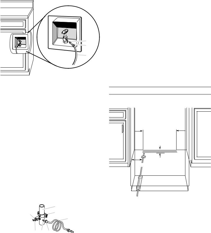
Style 1—Shutoff Valve Connection
NOTE: If your water line connection does not look like Style 1, see “Style 2—Copper Line Connection.”
1. Unplug refrigerator or disconnect power supply.
IMPORTANT:
■There is not enough clearance to achieve a flush installation if a water shutoff valve is located in the wall behind the refrigerator. The water shutoff should be located in the base cabinet on either side of the refrigerator.
■Before attaching the tubing to shutoff valve, flush the main water supply line to remove particles and air in the water line. Allow enough flow so that water becomes clear. Flushing the water line may help avoid filters and/or water valves from becoming clogged.
18
2. Connect the flexible, codes-approved water supply line to the |
6. |
Fasten the shutoff valve to the cold water pipe with the pipe |
|
water shutoff valve by threading the provided nut onto the |
|
clamp. Be sure the outlet end is solidly in the ¹⁄ " (6.35 mm) |
|
shutoff valve as shown. |
|
|
drilled hole in the water pipe and that the washer is under the |
|
|
|
pipe clamp. Tighten the packing nut. Tighten the pipe clamp |
|
|
|
screws slowly and evenly so washer makes a watertight seal. |
|
|
|
Do not overtighten. |
|
|
IMPORTANT: Before attaching the tubing to shutoff valve, flush |
|
|
|
the main water supply line to remove particles and air in the water |
|
|
|
line. Allow enough flow so that water becomes clear. Flushing the |
|
|
|
water line may help avoid filters and/or water valves from |
|
|
|
becoming clogged. |
|
|
|
7. |
Slip the compression sleeve and compression nut on the |
|
|
|
copper tubing as shown. Insert the end of the tubing into the |
|
A |
|
outlet end squarely as far as it will go. Screw compression nut |
|
|
onto outlet end with adjustable wrench. Do not overtighten the |
|
|
B |
|
clamp or the sleeve. This will crush the copper tubing. |
|
|
8. |
Turn off the shutoff valve on the water pipe. Coil the copper |
|
C |
|
tubing. |
|
9. |
Connect the flexible, codes-approved water supply line to the |
|
|
|
||
|
|
|
water shutoff valve by threading the provided nut onto the |
|
|
|
shutoff valve. |
|
|
10. |
Place the end of the tubing into a bucket, and turn shutoff |
|
|
|
valve ON. |
A. Bulb |
C. Water tubing |
11. |
Check for leaks around the saddle valve. Tighten any nuts or |
B. Nut |
|
|
connections (including connections at the valve) that leak. |
|
|
|
|
3. |
Place the end of the tubing into a bucket, and turn shutoff |
Connect to Refrigerator |
|
|
valve ON. |
|
|
4. |
Check for leaks. Tighten any nuts or connections (including |
Parts Supplied |
|
|
connections at the valve) that leak. |
■ ¹⁄ " to ¹⁄ " (6.35 mm to 6.35 mm) male-to-male coupling |
|
Style 2—Copper Line Connection |
|
|
|
NOTE: If there is a water supply line that meets the specifications |
|
|
|
in “Water Supply Requirements,” proceed to “Connecting to |
|
|
|
Refrigerator.” If not, use the following instructions to connect to |
|
|
|
the household cold water supply. |
6" |
6" |
|
1. |
Unplug refrigerator or disconnect power. |
(15.2 cm) |
(15.2 cm) |
2. |
Turn OFF main water supply. Turn ON nearest faucet long |
|
|
|
enough to clear line of water. |
|
|
3. |
Locate a ½" to 1¹⁄ " (1.25 cm to 3.18 cm) vertical cold water |
|
|
|
pipe near the refrigerator. |
|
|
|
IMPORTANT: |
|
|
|
■ Make sure it is a cold water pipe. |
|
|
|
■ Horizontal pipe will work, but drill on the top side of the |
7" |
1" |
|
(2.54 cm) |
||
|
pipe, not the bottom. This will help keep water away from |
||
|
(17.78 cm) |
|
|
|
the drill and keep normal sediment from collecting in the |
|
|
|
valve. |
|
|
4.Determine the length of copper tubing you need. Measure from the connection on the refrigerator to the water pipe. Add 7 ft (2.1 m) to allow for cleaning. Use ¹⁄ " (6.35 mm) O.D. (outside diameter) copper tubing. Be sure both ends of copper tubing are cut square.
5.Using a cordless drill, drill a ¹⁄ " (6.35 mm) hole in the cold water pipe you have selected.
|
A |
G |
B |
|
|
|
C |
F E |
D |
A. Cold water pipe |
E. Compression sleeve |
B. Pipe clamp |
F. Shutoff valve |
C. Copper tubing |
G. Packing nut |
D. Compression nut |
|
NOTE: The flexible, codes-approved water supply line should connect to the supply valve through the floor.
1.Unplug the refrigerator or disconnect power.
2.Connect the 7 ft (2.13 m) flexible codes-approved water tube to the water supply valve.
3.Flush the main water supply line to remove particles and air in the water line. Allow enough flow so that water becomes clear.
4.Tape the 7 ft (2.13 m) flexible codes-approved water supply line to the floor, 7" (17.78 cm) from the left side of the refrigerator. Tape along the length of the tubing, which will allow it to pass beneath the refrigerator without interference.
NOTE: Allow a minimum of 26" (66.04 cm) of flexible codesapproved water supply line to be loose at the front of the refrigerator for connecting to the refrigerator.
19
5.Connect the 7 ft (2.13 m) flexible codes-approved water supply line to the refrigerator.
NOTE: If the main water shutoff valve is behind the refrigerator, a secondary water shutoff valve may be installed in line with the water supply line at the front of the product.
D
C
B
A
F G
E
A. Household water line |
E. Bulb |
B. Nut (purchased) |
F. Nut |
C. Ferrule (purchased) |
G. Refrigerator water tubing |
D.Coupling
6.Turn on the water supply valve and check all connections for leaks.
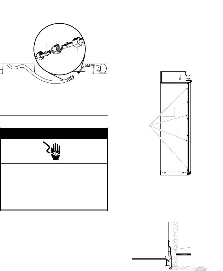
Plug in Refrigerator
 WARNING
Electrical Shock Hazard
Plug into a grounded 3 prong outlet.
Do not remove ground prong.
Do not use an adapter.
Do not use an extension cord.
Failure to follow these instructions can result in death, fire, or electrical shock.
1.Set control switch at top of cabinet to the OFF position.
2.Plug into a grounded 3 prong outlet.
Install Side Trims
The side trims cover the space between the refrigerator and the adjacent cabinets. There is a trim piece taped to each side of the refrigerator. Install each trim piece to the side of the refrigerator to which it is taped.
1.Remove the tape attaching the trim pieces to the sides of the refrigerator. Set the trim pieces aside.
IMPORTANT: Custom wood panel (with ¹⁄" gap) installations only - The bulb-shaped edge of the side trim piece will interfere with the panels. Peel the bulb-shaped, long edge from the trim piece and discard. See the “Top View” graphic later in this section.
2.Remove the four screws from the side of the refrigerator cabinet.
A
A.Side trim screws
3.Using the original holes and the screws removed in Step 2, fasten the side trim to the refrigerator cabinet.
NOTE: Make sure to fasten each trim piece to the side of the refrigerator cabinet from which it was removed. The bulbshaped edge should be forward with the notch at the top, as shown.
Top View
A |
B |
C |
D |
A. Side trim |
C. Door |
B. Adjacent cabinet |
D. Bulb-shaped edge |
20
Move Refrigerator to
Final Location
WARNING
Tip |
|
Refrigerator is top |
easily when not |
completely installed. |
|
Keep doors taped closed until refrigerator is completely installed.
Use two or more people to move and install refrigerator.
Failure to do so can result in death or serious injury.
IMPORTANT:
■A flush installation is NOT possible with a 24" (60.9 cm) deep opening.
■To avoid floor damage, make sure levelers are raised (not touching floor) and refrigerator is on rollers before moving.
■Use the installation block, attached to the door hinge, as a reference to make sure the refrigerator is pushed back far enough into the opening, so that when the panels are installed they will be flush with the adjacent cabinets.
■After the refrigerator is leveled and aligned, remove the installation block from the door hinge and use it to check the spacing between the panels and adjacent cabinets.
NOTE: The installation block is designed to provide accurate spacing for ³⁄ " (1.9 cm), ³⁄ " (9.53 mm) and ¹⁄ " (3.18 mm).
³⁄ " |
¹⁄ " |
|
(1.9 cm) |
||
(3.18 mm) |
||
|
||
|
³⁄ " |
|
|
(9.53 mm) |
1.Place top of cardboard carton or plywood under refrigerator. Remove dolly.
2.Move the refrigerator straight back and evenly into the opening. Be sure that the water tubing is not kinked and the power supply cord is on top of the refrigerator.
NOTE: If the power supply cord is behind the refrigerator, it will not install properly.
3.Make sure the installation block is flush with the adjacent cabinets.
NOTE: To achieve a flush installation, it is critical to verify a ³⁄ " (1.9 cm) depth from the front face of the adjacent cabinetry to the refrigerator.
A 
B 
³⁄ " (1.9 cm)
C
A.Adjacent cabinet or wall
B.Installation block
C.Face of refrigerator
Level and Align Refrigerator
WARNING
Tip |
|
Refrigerator is top |
easily when not |
completely installed. |
|
Keep doors taped closed until refrigerator is completely installed.
Use two or more people to move and install refrigerator.
Failure to do so can result in death or serious injury.
IMPORTANT: All four leveling legs must contact the floor to support and stabilize the full weight of refrigerator. Rollers are for moving refrigerator and not for permanent support.
After moving the refrigerator to its final location:
1.Use a ⁄ " socket driver to turn the leveling bolts clockwise to extend the legs to the floor as shown. The rollers should be off the floor.
A B |
A |
B |
A.Rear leveling bolt
B.Front leveling bolt
2.Adjust the leveling legs to level and align the refrigerator from left to right and front to back so that the refrigerator is level and aligned with the cabinets.
3.Continue adjusting the leveling legs until the top of the refrigerator is making contact with the bottom of the solid soffit, or the bottom of the anti-tip boards, if anti-tip boards were used. Do not crush the compressor cover.
21
IMPORTANT: Adjust in small increments to keep from damaging the cabinet trim and causing problems with the door alignment or top grille fit. To avoid damage to the cabinet or leveling legs, do not apply more than 50 inch-pounds (5.65 Nm) of torque to the leveling bolts. The leveling legs can be extended to a maximum of 1¹⁄" (3.18 cm) below the rollers.
A
 B
B
2" (5 cm) 
84" (213.4 cm)
C
D
A.Two 2" x 4" x 32" (5 cm x 10 cm x 81 cm) boards
B.Attach to studs with six #8 x 3" (7.6 cm) screws
C.Compressor cover
D.Distance from bottom of anti-tip boards to floor
4.After leveling the refrigerator, use a straight edge or 4-ft level going across the front of the refrigerator installation to the cabinets to check that the refrigerator is still flush.
Install Refrigerator and Panels
IMPORTANT: Jenn-Air is not responsible for the removal or addition of molding or wood overlay panels that would not allow access to the refrigerator for service.
Install Top Grille Filler (standard installation only)
IMPORTANT: The grille panel height allows the necessary airflow for refrigerator performance. The top grille filler hides the upper compartment cover behind the top grille. If you choose to modify the recommended grille panel dimensions, performance will be compromised.
Custom Wood Panel Models
1.In the custom made (1" x width of grille panel) wood filler piece, drill a hole ¹¹⁄" from each edge.
NOTE: Make sure the hole is centered in the 1" thickness of the wood piece.
2.Using slotted hex-head screws (provided with refrigerator), fasten an “L” bracket to each end of the wood filler piece.
3.Using hex-head blunt screws (provided with refrigerator), attach the “L” brackets to the top grille mounting plates.
4.Adjust the “L” brackets, so that the wood filler piece is flush with the bottom of the soffit. Completely tighten the screws.
A
B 
C 
A.Top grille filler
B.“L” bracket
C.Grille mounting plate
Side View
A |
B |
C |
D |
E |
A. Top grille filler |
D. Grille panel |
B. Soffit |
E. Door panel |
C. Airflow |
|
Stainless Steel Panel Kit Models
WARNING
Excessive Weight Hazard
Use two or more people to move and install panels. Failure to do so can result in back or other injury.
1.Align top grille vent (provided in the door kit) with the bottom edge of the soffit. Use as a template, and mark where to drill the holes.
22
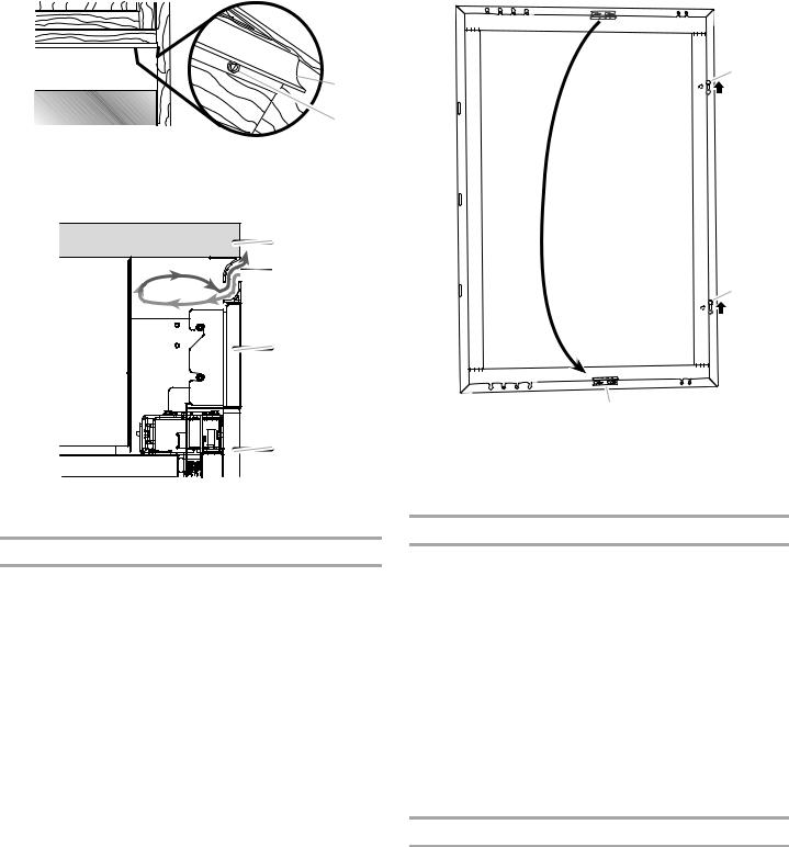
2.Using slotted hex-head screws (provided with refrigerator), attach the top grille vent to the soffit.
3.Using the installation block as a guide for depth, fasten the shoulder washers with the hex-head pointed screws into the predrilled holes marked with a blue “L.”
 A
A
B
A.Top grille vent
B.Slotted hex-head screw
Side View
A |
B |
C |
D |
A. Soffit |
C. Grille panel |
B. Airflow |
D. Door panel |
Jenn-Air Stainless Steel Panel Kits (only)
IMPORTANT: The panels included in the panel kits come with the mounting bracket preinstalled and are prepared for installation.
36" Single Door Models - Door Panel Kit (only)
These panels are designed for refrigerator doors with the hinges installed on the right-hand side. If you reverse the door swing, you must move the door panel mounting bracket and the shoulder washers.
To modify the door panel for a left-hand swing door:
1.Remove the mounting bracket from one end of the door panel and reinstall it on the opposite end of the panel into the predrilled holes.
NOTE: The end with the mounting bracket is now the top of the door panel.
2.Remove the hex-head pointed screws and shoulder washers from the holes marked with a red “R.”
A |
A |
B
A.Move shoulder washers from Hole R to Hole L.
B.Move mounting bracket.
4.Peel back the film cover on the door panel in the area of the brackets and shoulder washers only. Do not fully remove the film covering until the installation is complete.
Custom Wood Panels - Predrill Panels
IMPORTANT: The custom panel template shipped with the refrigerator can be used for either a ³⁄ " (0.95 cm) or a ¹⁄ " (0.32 cm) reveal installation.
■The drilling templates are used only for custom wood overlay panels.
■The drilling templates are double-sided.
■The drilling holes are precut into the template.
1.On the template, locate the diagram of your refrigerator. Then, follow the letters and colored arrows to place correctly the drilling template on the back side of the panels.
NOTE: Check the direction of the arrows to determine which holes to mark when the template is aligned at the top of the panel and which holes to mark when the template is aligned at the bottom of the panel.
2.Predrill pilot holes into the wood rails bordering the door(s), drawer and top grille panels.
Custom Wood Panels - Prepare Panels
Door Panel
IMPORTANT: This step is complete on Jenn-Air Stainless Steel Panel Kits.
1.Place panels on a firm, covered, flat surface with the front facing down.
2.Locate the 2 predrilled holes in the handle side edge of the door panel.
23
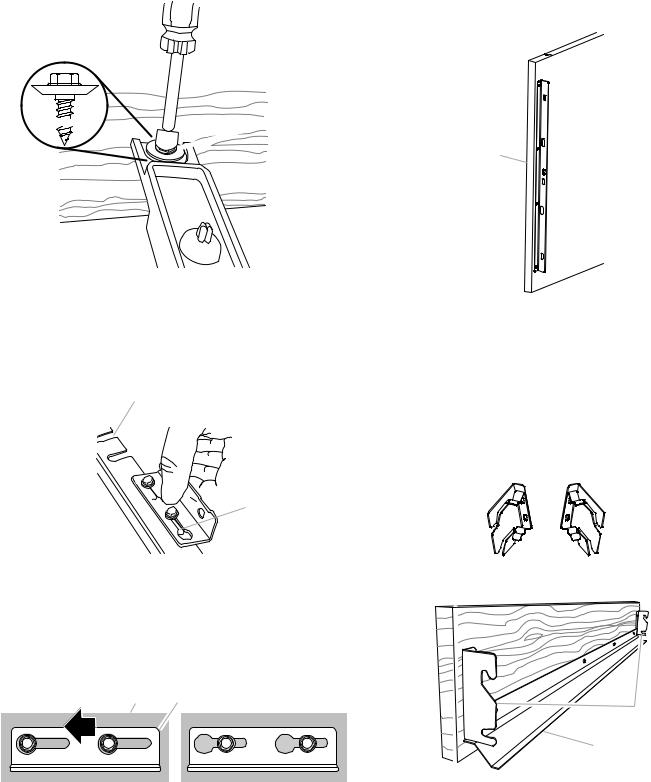
3.Using the installation block as a guide for depth, attach a shoulder washer with a hex-head pointed screw (both provided with refrigerator) into the predrilled door panel (2 per door).

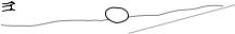 A
A
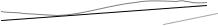 B
B
A.Shoulder washer and hex-head pointed screw
B.Installation block
4.For the mounting bracket, insert the hex-head pointed screws (provided with refrigerator) into the wood holes at the top of the door panels where they were predrilled.
NOTE: It is critical to use the ⁄" screw, the longest length provided, to attach the bracket to the top of the door panel.
A

 B
B
Drawer Panel
IMPORTANT: This step is complete on Jenn-Air Stainless Steel Panel Kits.
1.Using the Phillips-head flat screws (provided with refrigerator), fasten a drawer panel bracket to each side of the drawer panel, as shown.
A
 B
B
A.Drawer panel
B.Drawer panel mounting bracket
Top Grille Panel
IMPORTANT: This step is complete on Jenn-Air Stainless Steel Panel Kits.
1.Using the slotted hex-head screws (provided with refrigerator), attach a mounting bracket to each side of the top grille panel.
IMPORTANT: See the “Parts Provided” section to select the brackets designated for your installation.
■Use the Fully Integrated Grille brackets for a fully integrated grille installation with a full height grille.
A.U-shaped hole
B.Slot
5.Attach a panel top bracket to the top edge of the door panel(s) by placing the large ends of the keyhole slots over the screws and sliding the bracket so that the screws are centered in the slots.
NOTE: Start with the screws in the center of the slots as shown, then move the door panel, as necessary, to align.
A B
A.Door panel
B.Panel top bracket
■Use the standard grille brackets for a Standard Integrated Grille installation, as shown.
A
B
A.Top grille brackets
B.White, grille trim piece (taped to refrigerator door)
2.Using round-head screws (provided with refrigerator), attach the grille trim piece to the bottom of the grill panel.
NOTE: The grille trim piece in the stainless steel panel kits is preinstalled on the grille.
24
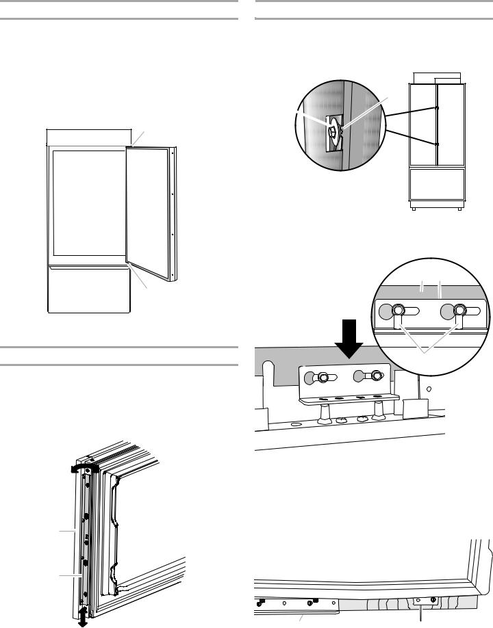
Remove Trim Pieces
1.Remove all tape and door bracing from the refrigerator and freezer doors.
2.Open the refrigerator and freezer doors.
3.Remove the hinge cover trim pieces from the top and bottom of the door to expose the holes in the hinges.
NOTES:
■It is not necessary to remove the hinge side trims as they will not interfere with the installation.
■Leave the freezer drawer trims in place for installation.
A
 B
B
A
A.Hinge cover pieces
B.Door adjustment pin cover
Install Drawer Panel
1.Align the slots in the door panel brackets, located on each side of the drawer panel, with the holes that go through the drawer trim and into the drawer.
2.Using Phillips-head flat screws (provided with refrigerator), attach the brackets to the drawer.
3.Move the drawer panel up and down or from side to side to align. Do not fully tighten the screws.
Install Door Panels
IMPORTANT: Use the foam packaging to prop and hold the door(s) open while installing a door panel.
1.Align the two shoulder washers, on the back of the door panel, with the “J” slots on the side of the refrigerator door. Slide the panel onto the door.
B
A 
A.Shoulder washer and hex-head pointed screw
B.“J” slot
2.Lower the panel bracket down onto the adjustment pins at the top of the door.
A B
C
A
B
A.Drawer overlay panel
B.Drawer panel bracket
A. Door panel |
C. Adjustment pins |
B.Panel top bracket
3.French door models, repeat steps 1 through 2 to install the second door panel.
4.Using slotted hex-head screws (provided with refrigerator), attach the mounting bracket (factory installed), located at the bottom of the refrigerator and freezer doors, to the respective door panels. Do not fully tighten the screw.
A B
A.Bottom hinge
B.Mounting bracket
25

Install Top Grille Panel
B A B
A.Top grille panel
B.Cabinet sides
Standard Integrated Grille Installation
1.Hook the panel brackets onto the mounting bolts extending from the top of the refrigerator.
A
B
A.Panel brackets
B.Grill trim piece
2.Pull the grille panel down slightly to lock into place.
Fully Integrated Grille Installation—Full Height Grille
1.Align the bracket on each side of the top grille panel with the mounting bolts.
Complete Panel Installation
1.Use the installation block to measure the gaps between the panels and adjacent cabinets.
■Custom wood overlay panels may be made with a ³⁄" (0.95 cm) or ¹⁄" (0.32 cm) gap between the panel and cabinets and a ¹⁄" (0.32 cm) gap between the freezer and refrigerator door(s) and the door(s) and top grille.
■All stainless steel panel kits require a ³⁄" (0.95 cm) gap between the panel and the cabinets and a ¹⁄" (0.32 cm) gap between the freezer and refrigerator door(s), and the door(s) and top grille.
A 
 C
C
B 
A. Adjacent cabinet |
C. Panel on door |
B.Installation block
2.Adjust the panel to achieve the required spacing, or to align.
IMPORTANT: If adjustments are needed, adjust the panel, not the door. Adjust left to right in the mounting bracket before using the pins to adjust the panel up and down or at an angle.
■Slide the panel from side to side in the keyhole slot.
■Use a ⁄" hex key to raise or lower the adjustment pins which allows the door panel to swivel.
 A
A
 B
B
2.Push the grille panel forward until the bracket snaps into place.
Door Swing Adjustment
It may be necessary to adjust the swing of the door(s). Make sure the refrigerator door(s) can open freely. If the door(s) opens too wide, install the door stop pin (provided with refrigerator).
1.Hold the door open to a position that is less than 90°.
2.Insert the door stop pin into the top hinge in the hole shown.
3.Using a ⁄" hex key, tighten the door stop pin.
A
C
A. Door panel C. Adjustment pins
B.Panel top bracket
3.Predrill pilot holes, using an ³⁄" drill bit, into the door panel(s) through the open holes in both the bottom and top hinges.
4.Using the slotted hex-head screws (provided with refrigerator), attach the top and bottom hinges to the door panels. Fully tighten all door panel screws.
NOTE: For 36" single door models, there is an additional bracket at the top to fasten the panel to the door. Insert the screws through the bracket into the door panel.
A B
|
C |
D |
E |
|
A. Top hinge |
D. Door adjustment pins |
|
A. Door stop pin hole |
B. Panel top bracket |
E. Holes for screws |
|
C. Holes for screws |
(36" models only) |
|
26
 Loading...