

Jenn-Air JDS1450FS, JDS1450FP Installation Instructions

INSTALLATION INSTRUCTIONS
SLIDE-IN DUAL-FUEL RANGES
INSTRUCTIONS D’INSTALLATION DES CUISINIÈRES
AUX BI-COMBUSTIBLES ENCASTRABLES
Table of Contents/Table des matières
RANGE SAFETY .............................................................................2
INSTALLATION REQUIREMENTS .................................................4
Tools and Parts ............................................................................. 4
Location Requirements ................................................................4
Electrical Requirements - U.S.A. Only .........................................7
Electrical Requirements - Canada Only .......................................8
Gas Supply Requirements ...........................................................8
INSTALLATION INSTRUCTIONS .................................................10
Unpack Range............................................................................10
Install Anti-Tip Bracket ...............................................................10
Adjust Leveling Legs ..................................................................11
Level Range ................................................................................12
Electrical Connection - U.S.A. Only ...........................................12
Make Gas Connection ...............................................................18
Verify Anti-Tip Bracket Is Installed and Engaged ......................19
Electronic Ignition System .........................................................20
Remove/Replace Drawer ...........................................................20
Oven Door ..................................................................................21
Complete Installation .................................................................21
GAS CONVERSIONS ....................................................................22
Propane Gas Conversion ...........................................................22
Natural Gas Conversion .............................................................24
Adjust Flame Height ...................................................................26
SÉCURITÉ DE LA CUISINIÈRE ...................................................27
EXIGENCES D’INSTALLATION ...................................................29
Outils et pièces ...........................................................................29
Exigences d’emplacement .........................................................29
Spécications électriques – Canada seulement .......................32
Spécications de l’alimentation en gaz .....................................32
INSTRUCTIONS D’INSTALLATION .............................................34
Déballage de la cuisinière ..........................................................34
Installation de la bride antibasculement ....................................34
Réglage des pieds de nivellement .............................................35
Réglage de l’aplomb de la cuisinière .........................................36
Raccordement au gaz ................................................................36
Vérier que la bride antibasculement est bien installée
et engagée ..................................................................................38
Système d’allumage électronique..............................................39
Dépose et réinstallation du tiroir ................................................39
Porte du four ..............................................................................40
Achever l’installation ..................................................................41
CONVERSIONS POUR CHANGEMENT DE GAZ ......................42
Conversion pour l’alimentation au propane ..............................42
Conversion pour l’alimentation au gaz naturel ..........................44
Réglage de la taille des ammes ...............................................47
IMPORTANT:
Save for local electrical inspector's use.
IMPORTANT :
À conserver pour consultation par l'inspecteur local des installations électriques.
W11259378A
RANGE SAFETY
Your safety and the safety of others are very important.
We have provided many important safety messages in this manual and on your appliance. Always read and obey all safety
messages.
This is the safety alert symbol.
This symbol alerts you to potential hazards that can kill or hurt you and others.
All safety messages will follow the safety alert symbol and either the word “DANGER” or “WARNING.”
These words mean:
You can be killed or seriously injured if you don't immediately
DANGER
WARNING
All safety messages will tell you what the potential hazard is, tell you how to reduce the chance of injury, and tell you what can
happen if the instructions are not followed.
WARNING: If the information in these instructions is not followed exactly, a fire or
explosion may result causing property damage, personal injury or death.
follow instructions.
You
can be killed or seriously injured if you don't
instructions.
follow
– Do not store or use gasoline or other flammable vapors and liquids in the vicinity of this
or any other appliance.
– WHAT TO DO IF YOU SMELL GAS:
Do not try to light any appliance.
•
Do not touch any electrical switch.
•
Do not use any phone in your building.
•
Immediately call your gas supplier from a neighbor's phone. Follow the gas supplier's
•
instructions.
If you cannot reach your gas supplier, call the fire department.
•
Installation and service must be performed by a qualified installer, service agency or
–
the gas supplier.
WARNING: Gas leaks cannot always be detected by smell.
Gas suppliers recommend that you use a gas detector approved by UL or CSA.
For more information, contact your gas supplier.
If a gas leak is detected, follow the “What to do if you smell gas” instructions.
IMPORTANT: Do not install a ventilation system that blows air downward toward this gas cooking appliance. This type of
ventilation system may cause ignition and combustion problems with this gas cooking appliance resulting in personal injury or
unintended operation.
2
In the State of Massachusetts, the following installation instructions apply:
Installations and repairs must be performed by a qualified or licensed contractor, plumber, or gasfitter qualified or licensed by
the State of Massachusetts.
Acceptable Shut-off Devices: Gas Cocks and Ball Valves installed for use shall be listed.
A flexible gas connector, when used,must not exceed 4 feet (121.9 cm).
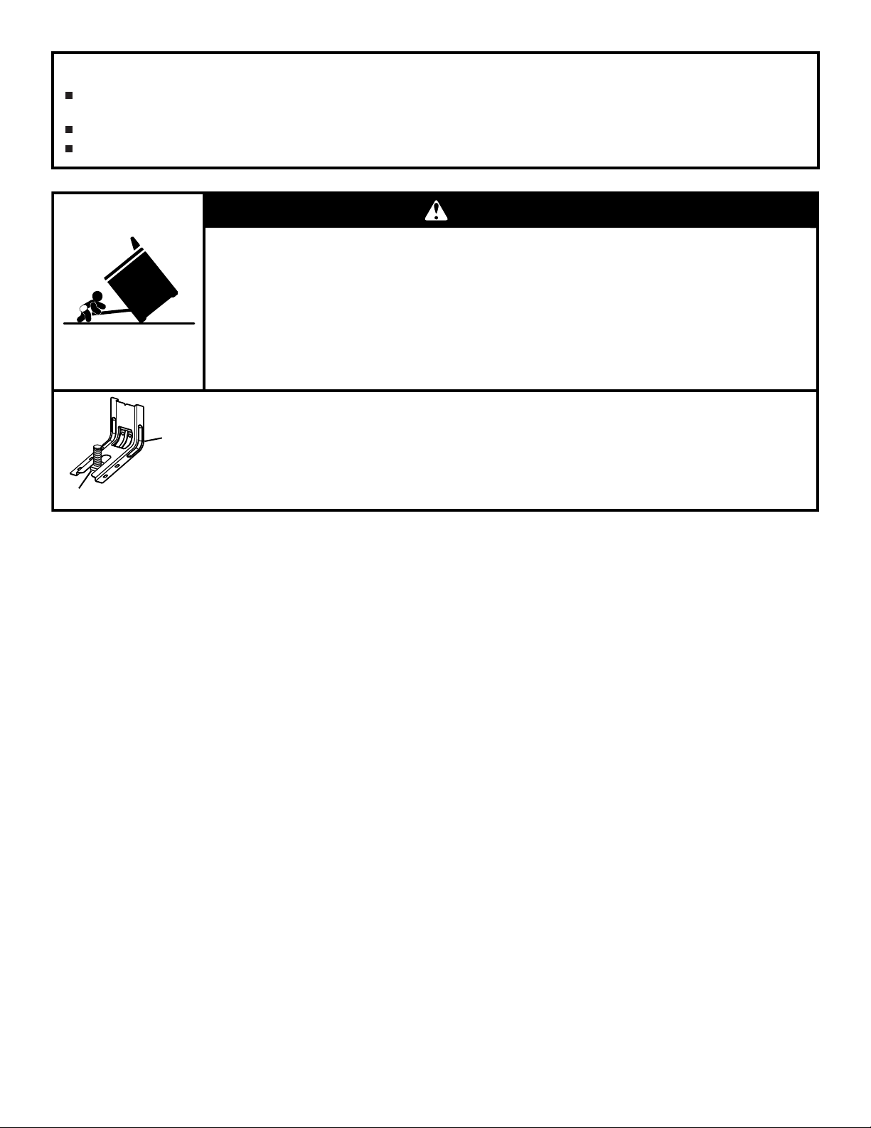
Range Foot
Anti-Tip
Bracket
WARNING
Tip Over Hazard
A child or adult can tip the range and be killed.
Install anti-tip bracket to floor or wall per installation instructions.
Slide range back so rear range foot is engaged in the slot of the anti-tip bracket.
Re-engage anti-tip bracket if range is moved.
Do not operate range without anti-tip bracket installed and engaged.
Failure to follow these instructions can result in death or serious burns to children and adults.
To verify the anti-tip bracket is installed and engaged:
• Slide range forward.
• Look for the anti-tip bracket securely attached to floor or wall.
• Slide range back so rear range foot is under anti-tip bracket.
• See installation instructions for details.
3

INSTALLATION REQUIREMENTS
Tools and Parts
Gather the required tools and parts before starting installation.
Read and follow the instructions provided with any tools listed
here.
Tools Needed
■ Tape measure
■ Phillips screwdriver
■ Flat-blade screwdriver
■ 1/8" (3 mm) at-blade
screwdriver
■ Level
■ Drill
■ Wrench or pliers
■ Pipe wrench
■ 15/16" (2.4 cm) combination
wrench
■ 1/8" (3.2 mm) drill bit (for
wood oors)
■ Marker or pencil
Parts Supplied
Check that all parts are included.
■ Propane/Natural Gas Conversion Kit
■ 10-32 hex nuts (attached to terminal block) (3)
■ Direct wire lugs (3)
■ #10 x 1
■ Anti-tip bracket (inside oven cavity)
5
/8" (4.1 cm) screws (for mounting anti-tip bracket) (2)
Anti-tip bracket must be securely mounted to the back wall
or oor. Thickness of ooring may require longer screws to
anchor bracket to suboor. Longer screws are available from
your local hardware store.
■ Pipe-joint compound
resistant to Propane gas
■ 3/16" (4.8 mm) carbide-
tipped
masonry drill bit (for
concrete/ceramic oors)
■ Noncorrosive leak-detection
solution
For Propane/Natural Gas
Conversions
■ 1/2" (1.3 cm) combination
wrench
■ 1/4" (6 mm) nut driver
■ 9/32" (7 mm) nut driver
■ Masking tape
Parts Needed
If using a power supply cord kit:
■ A UL listed power supply cord kit marked for use with
ranges. The cord should be rated at 250 V minimum,
40 A or 50 A that is marked for use with nominal
1³⁄8" (3.5 cm) diameter connection opening and must end in
ring terminals or open-end spade terminals with upturned
ends.
■ A UL listed strain relief.
Check local codes and consult gas supplier. Check existing
gas supply and electrical supply. See the appropriate “Electrical
Requirements” and “Gas Supply Requirements” sections.
It is recommended that all electrical connections be made by a
licensed, qualied electrical installer.
Optional Parts
To purchase these or any other accessories, please reference the
“Accessories” section of the User Guide for contact information.
■ Side Trim Kits:
5/8" (1.7 cm) White - Order Part Number W10675027
5/8" (1.7 cm) Black - Order Part Number W10675026
5/8" (1.7 cm) Stainless Steel - Order Part Number
W10675028
11/8" (2.9 cm) White - Order Part Number W10731885
11/8" (2.9 cm) Black - Order Part Number W10731886
11/8" (2.9 cm) Stainless Steel - Order Part Number
W10731887
■ Backsplash Kits:
High 6" (15.2 cm) White - Order Part Number W10655448
High 6" (15.2 cm) Black - Order Part Number W10655449
High 6" (15.2 cm) Stainless Steel - Order Part Number
W10655450
Location Requirements
IMPORTANT: Observe all governing codes and ordinances. Do
not obstruct ow of combustion and ventilation air.
■ It is the installer’s responsibility to comply with installation
clearances specied on the model/serial/rating plate. The
model/serial/rating plate is located behind the oven door on
the top right-hand side of the oven frame.
■ The range should be located for convenient use in the
kitchen.
■ Recessed installations must provide complete enclosure of
the sides and rear of the range.
■ All openings in the wall or oor where range is to be installed
must be sealed.
■ Cabinet opening dimensions that are shown must be used.
Given dimensions are minimum clearances.
4
■ The anti-tip bracket must be installed. To install the anti-tip
B.
C.
D.
screwed in all the way*
" (71.9 cm) max. depth
bracket shipped with the range, see “Install Anti-Tip Bracket”
section.
■ Grounded electrical supply is required. See the appropriate
“Electrical Requirements” section.
■ Proper gas supply connection must be available. See “Gas
Supply Requirements” section.
■ Contact a qualied oor covering installer to check that the
oor covering can withstand at least 200°F (93°C).
■ Use an insulated pad or 1/4" (6.4 mm) plywood under range
if installing range over carpeting.
IMPORTANT: To avoid damage to your cabinets, check with
your builder or cabinet supplier to make sure that the materials
used will not discolor, delaminate or sustain other damage. This
oven has been designed in accordance with the requirements
of UL and CSA International and complies with the maximum
allowable wood cabinet temperatures of 194°F (90°C).
Mobile Home - Additional Installation Requirements
The installation of this range must conform to the Manufactured
Home Construction and Safety Standard, Title 24 CFR,
Part 3280 (formerly the Federal Standard for Mobile Home
Construction and Safety, Title 24, HUD Part 280). When such
standard is not applicable, use the Standard for Manufactured
Home Installations, ANSI A225.1/NFPA 501A or with local codes.
In Canada, the installation of this range must conform with the
current standards CAN/CSA-A240-latest edition, or with local
codes.
Mobile Home Installations Require:
■ When this range is installed in a mobile home, it must be
secured to the oor during transit. Any method of securing
the range is adequate as long as it conforms to the
standards listed above.
■ Four-wire power supply cord or cable must be used in a
mobile home installation. The appliance wiring will need
to be revised. See “Electrical Connection - U.S.A. Only”
section.
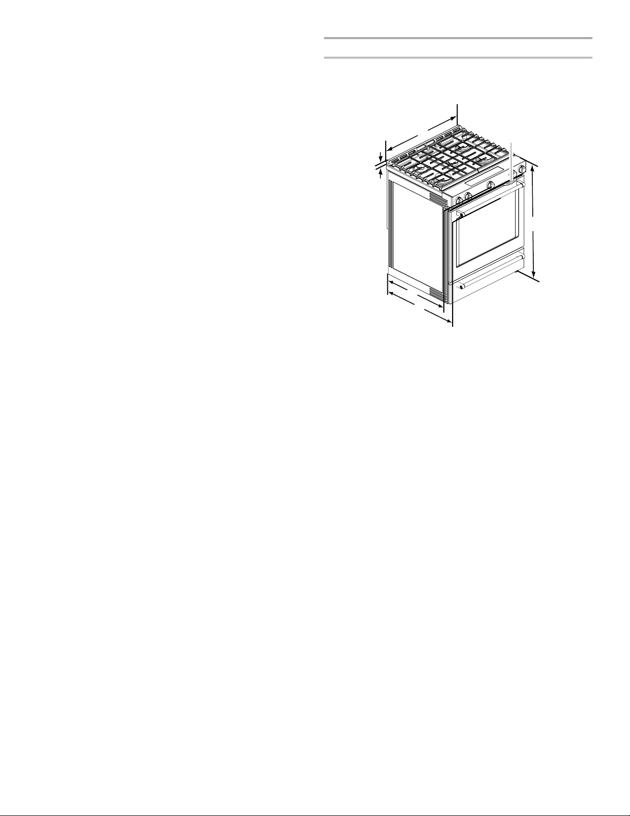
Product Dimensions
This manual covers several models. Your model may appear
different from the models depicted. Dimensions given are
maximum dimensions across all models.
B
A
E
F
A.1
³⁄₁₆
" (3.0 cm) height from cooktop
to top of vent
29
⁷⁄₈
" (75.9 cm)
Model/serial/rating plate (located
behind the oven door on the top
right-hand side of the oven frame)
36" (91.4 cm) height to top of
cooktop edge with leveling legs
E. 28
F. 28
IMPORTANT: Range must be level after installation. Follow the
instructions in the “Level Range” section. Using the cooktop as a
reference for leveling the range is not recommended.
*Range can be raised approximately 1" (2.5 cm) by adjusting the
leveling legs.
C
D
⁵⁄₁₆
from front of console to
back of range
" (73.3 cm) max. depth
⁷⁄₈
from handle to back of
range
5
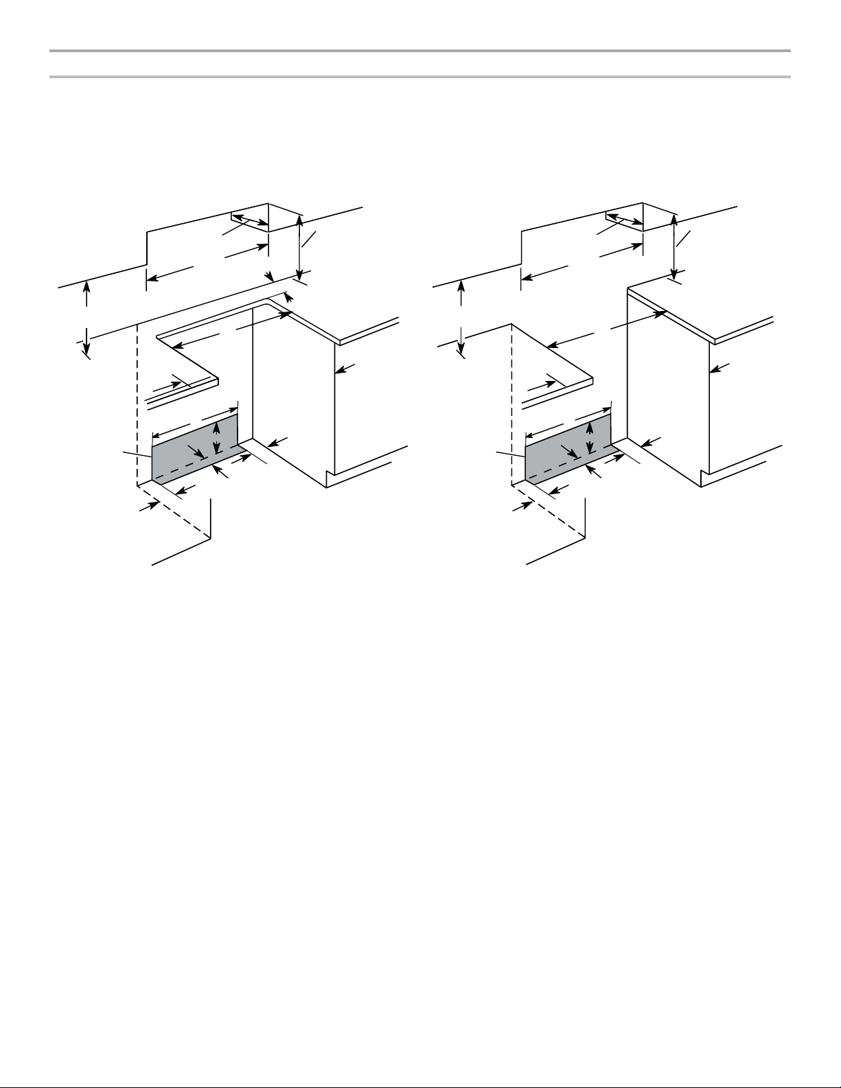
Cabinet Dimensions
tuotuC gnidnatseerFtuotuC ni-edilS
A. 18" (45.7 cm) upper side cabinet to countertop
B. 13" (33 cm) max. upper cabinet depth
C. 30" (76.2 cm) min. opening width
D. For minimum clearance to top of cooktop, see NOTE*.
E. 30" (76.2 cm) min. opening width
F. 3" (7.6 cm) min. clearance from bo th sides of range to side wall or
other combustible material
G. The shaded area is recommended fo r installation of rigid gas pipe
and grounded outlet.
H. 13
¹⁄₈
" (33.3 cm)
I. 7
¹¹⁄₁₆
" (19.5 cm)
J. 4
¹³⁄₁₆
" (12.2 cm)
K. 3
¹¹⁄₁₆
" (9.4 cm) plus measurement of M
L. Cabinet door or hinges should not extend into the cutout.
M. Remaining counter depth shou ld not exceed 2¼" (5.7 cm).
L
A
B
C
D
E
F
M
H
I
J
K
G
J
A. 18" (45.7 cm) upper side cabinet to countertop
B. 13" (33 cm) max. upper cabinet depth
C. 30" (76.2 cm) min. opening width
D. For minimum clearance to top of cooktop, see NOTE*.
E. 30" (76.2 cm) min. opening width
F. 3" (7.6 cm) min. clearance from bo th sides of range to side wall or
other combustible material
G. The shaded area is recommended for installation of rigid gas pipe
and grounded outlet.
H. 13
¹⁄₈
" (33.3 cm)
I. 7
¹¹⁄₁₆
" (19.5 cm)
J. 4
¹³⁄₁₆
" (12.2 cm)
K. 3
¹¹⁄₁₆
" (9.4 cm)
L. Cabinet door or hinges should not extend into the cutout.
L
A
B
C
D
E
F
H
I
J
K
G
J
Cabinet opening dimensions shown are for 25" (64.0 cm) countertop depth, 24" (61.0 cm) base cabinet depth and 36" (91.4 cm)
countertop height.
IMPORTANT: If installing a range hood or microwave hood combination above the cooking surface, follow the range hood or
microwave hood combination installation instructions for dimensional clearances above the cooktop surface.
Range may be installed next to combustible walls with zero clearance.
NOTE: When installed in a slide-in cutout, the front of oven door may protrude beyond the base cabinet.
*NOTE: 24" (61.0 cm) minimum when bottom of wood or metal cabinet is shielded by not less than 1/4" (6.4 mm) ame retardant
millboard covered with not less than No. 28 MSG sheet steel, 0.015" (0.4 mm) stainless steel, 0.024" (0.6 mm) aluminum or 0.020"
(0.5 mm) copper.
30" (76.2 cm) minimum clearance between the top of the cooking platform and the bottom of an uncovered wood or metal cabinet.
6
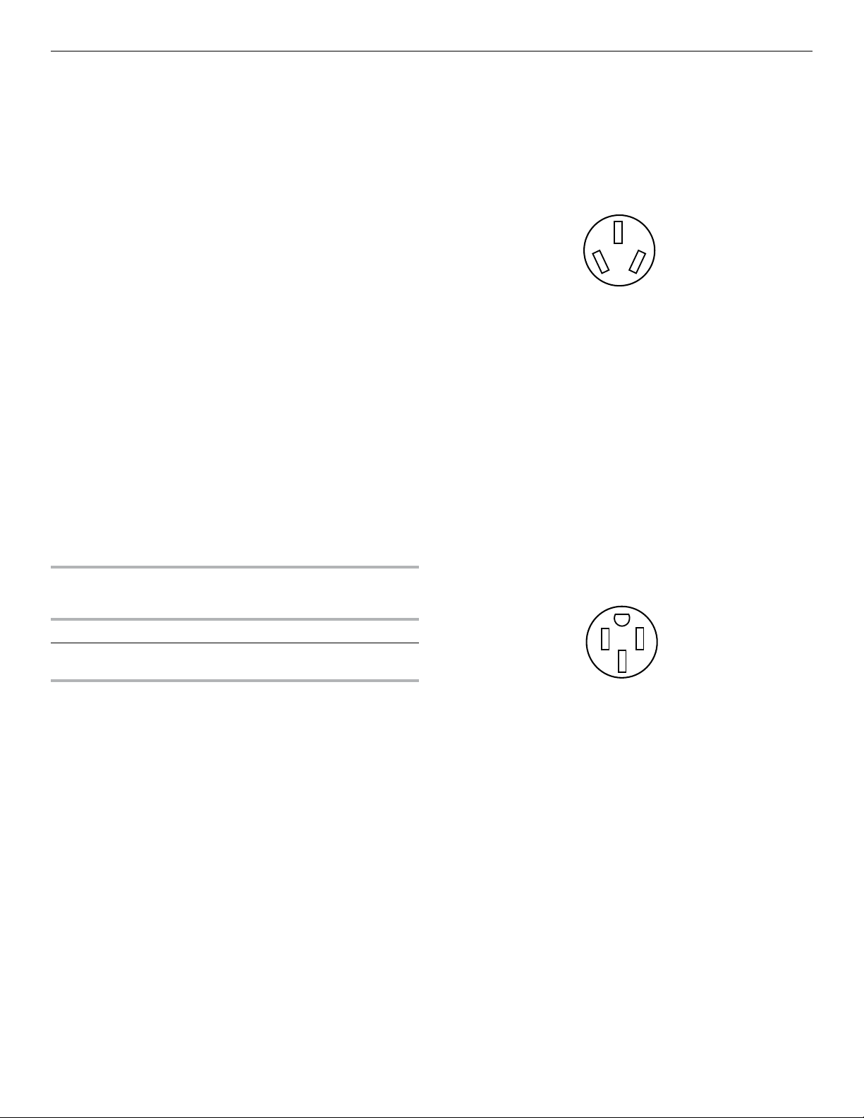
Electrical Requirements - U.S.A. Only
3-wire receptacle (10-50R)
4-wire receptacle (14-50R)
If codes permit and a separate ground wire is used, it is
recommended that a qualied electrical installer determine that
the ground path and wire gauge are in accordance with local
codes.
Do not use an extension cord.
Be sure that the electrical connection and wire size are adequate
and in conformance with the National Electrical Code, ANSI/
NFPA 70-latest edition and all local codes and ordinances.
A copy of the above code standards can be obtained from:
National Fire Protection Association
WARNING: Improper connection of the equipment-grounding
conductor can result in a risk of electric shock. Check with a
qualied electrician or service technician if you are in doubt as to
whether the appliance is properly grounded. Do not modify the
power supply cord plug. If it will not t the outlet, have a proper
outlet installed by a qualied electrician.
Electrical Connection
To properly install your range, you must determine the type of
electrical connection you will be using and follow the instructions
provided for it here.
■ Range must be connected to the proper electrical voltage
and frequency as specied on the model/serial/rating plate.
The model/serial/rating plate is located behind the oven door
on the top right-hand side of the oven frame.
■ This range is manufactured with the neutral terminal
connected to the cabinet. Use a 3-wire, UL listed, 40 or
50 A power supply cord (pigtail). See the following Range
Rating chart. If local codes do not permit ground through the
neutral, use a 4-wire power supply cord rated at 250 V,
40 or 50 A and investigated for use with ranges.
120/240 Volts 120/208 Volts Amps
8.8 - 16.5 KW
16.6 - 22.5 KW
1 Batterymarch Park
Quincy, MA 02169-7471
Power Supply Cord Kit
and Circuit Protection
7.8 - 12.5 KW
12.6 - 18.5 KW
40 or 50**
50
fo gnitaR deificepS*gnitaR egnaR
If Connecting to a 3-Wire System:
Local codes may permit the use of a UL listed, 3-wire, 250 V,
40 or 50 A range power supply cord (pigtail). This cord contains
3 copper conductors with ring terminals or open-end spade
terminals with upturned ends, terminating in a NEMA Type 1050P plug on the supply end. Connectors on the appliance end
must be provided at the point the power supply cord enters the
appliance. This uses a 3-wire receptacle of NEMA Type
10-50R.
If Connecting to a 4-Wire System:
This range is manufactured with the ground connected to the
neutral by a link. The ground must be revised so the green
ground wire of the 4-wire power supply cord is connected to the
cabinet. See “Electrical Connection - U.S.A. Only” section.
Grounding through the neutral conductor is prohibited for new
branch-circuit installations (1996 NEC); mobile homes; and
recreational vehicles, or an area where local codes prohibit
grounding through the neutral conductor.
When a 4-wire receptacle of NEMA Type 14-50R is used, a
matching UL listed, 4-wire, 250 V, 40 or 50 A, range power
supply cord (pigtail) must be used. This cord contains 4 copper
conductors with ring terminals or open-end spade terminals with
upturned ends, terminating in a NEMA Type
14-50P plug on the supply end.
The fourth (grounding) conductor must be identied by a green
or green/yellow cover and the neutral conductor by a white
cover. Cord should be Type SRD or SRDT with a UL listed strain
relief and be at least 4 ft (1.22 m) long.
*The NEC calculated load is less than the total connected load
listed on the model/serial/rating plate.
**If connecting to a 50 A circuit, use a 50 A rated cord with
kit. For 50 A rated cord kits, use kits that specify use with a
nominal 1³⁄8" (3.5 cm) diameter connection opening.
■ A circuit breaker is recommended.
■ The range can be connected directly to the circuit breaker
box (or fused disconnect) through exible or nonmetallic
sheathed, copper or aluminum cable. See the “Electrical
Connection - U.S.A. Only” section.
■ Allow at least 6 ft (1.8 m) of slack in the line so that the range
can be moved if servicing is ever necessary.
■ A UL listed conduit connector must be provided at each end
of the power supply cable (at the range and at the junction
box).
■ Wire sizes and connections must conform with the rating of
the range.
■ The tech sheet and wiring diagram are located on the back of
the range in a plastic bag.
The minimum conductor sized for the copper 4-wire power cord
are:
40 A circuit
2 No.-8 conductors
1 No.-10 white neutral
1 No.-10 green grounding
7
Electrical Requirements - Canada Only
Gas Supply Requirements
WARNING
Electrical Shock Hazard
Electrically ground range.
Failure to do so can result in death, fire, or
electrical shock.
If codes permit and a separate ground wire is used, it is
recommended that a qualied electrical installer determine that
the ground path is adequate and wire gauge are in accordance
with local codes.
Be sure that the electrical connection and wire size are adequate
and in conformance with CSA Standard C22.1, Canadian
Electrical Code, Part 1 - latest edition, and all local codes and
ordinances.
A copy of the above code standards can be obtained from:
Canadian Standards Association
178 Rexdale Blvd.
Toronto, ON M9W 1R3 CANADA
■ Check with a qualied electrical installer if you are not sure
the range is properly grounded.
Power Supply Cord Kit
and Circuit Protection
120/240 Volts 120/208 Volts Amps
8.8 - 16.5 KW
16.6 - 22.5 KW
*The NEC calculated load is less than the total connected load
listed on the model/serial/rating plate.
**If connecting to a 50 A circuit, use a 50 A rated cord with
kit. For 50 A rated cord kits, use kits that specify use with a
nominal 1³⁄8" (3.5 cm) diameter connection opening.
■ A circuit breaker is recommended.
■ This range is equipped with a CSA International Certied
Power Cord intended to be plugged into a standard 14-50R
wall receptacle. Be sure the wall receptacle is within reach of
range’s nal location.
7.8 - 12.5 KW
12.6 - 18.5 KW
40 or 50**
50
fo gnitaR deificepS*gnitaR egnaR
WARNING
Explosion Hazard
Use a new CSA International approved gas supply line.
Install a shut-off valve.
Securely tighten all gas connections.
If connected to propane, have a qualified person make
sure gas pressure does not exceed 14" (36 cm) water
column.
Examples of a qualified person include:
licensed heating personnel,
authorized gas company personnel, and
authorized service personnel.
Failure to do so can result in death, explosion, or fire.
Observe all governing codes and ordinances.
IMPORTANT: This installation must conform with all local codes
and ordinances. In the absence of local codes, installation must
conform with American National Standard, National Fuel Gas
Code ANSI Z223.1 - latest edition or CAN/CGA B149 - latest
edition.
IMPORTANT: Leak testing of the range must be conducted
according to the manufacturer’s instructions.
Type of Gas
Natural Gas:
■ This range is factory-set for use with Natural gas. See “Gas
Conversions” section. The model/serial/rating plate located
on the oven frame behind the top right-hand side of the oven
door has information on the types of gas that can be used. If
the types of gas listed do not include the type of gas available,
check with the local gas supplier.
Propane Gas Conversion:
Conversion must be done by a qualied service technician.
No attempt shall be made to convert the appliance from the gas
specied on the model/serial/rating plate for use with a different
gas without consulting the serving gas supplier. See “Gas
Conversions” section.
■ Do not use an extension cord.
■ The tech sheet and wiring diagram are located on the back
of the range in a plastic bag.
8
Gas Supply Line
■ Provide a gas supply line of 3/4" (1.9 cm) rigid pipe to the
range location. A smaller size pipe on longer runs may
result in insufcient gas supply. With Propane gas, piping or
tubing size can be 1/2" (1.3 cm) minimum. Usually, Propane
gas suppliers determine the size and materials used in the
system.
NOTE: Pipe-joint compounds that resist the action of
Propane gas must be used. Do not use TEFLON®† tape.
†®TEFLON is a registered trademark of Chemours.
Flexible Metal Appliance Connector:
A
C
■ If local codes permit, a new CSA design-certied, 4 to 5 ft
(122 to 152.4 cm) long, 1/2" or 3/4" (1.3 or 1.9 cm) I.D.
(inside diameter), exible metal appliance connector may
be used for connecting range to the gas supply line.
■ A 1/2" (1.3 cm) male pipe thread is needed for connection
to the female pipe threads of the inlet to the appliance
pressure regulator.
■ Do not kink or damage the exible metal tubing when
moving the range.
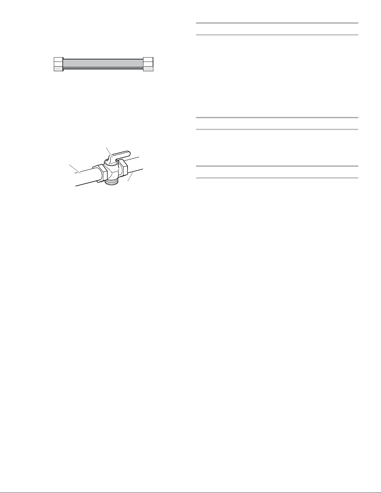
■ Must include a shut-off valve:
Install a manual gas line shut-off valve in an easily accessible
location. Do not block access to shut-off valve. The valve is
for turning on or shutting off gas to the range.
B
A. Gas supply line
B. Shut-off valve “open” position
C. To range
Gas Pressure Regulator
The gas pressure regulator supplied with this range must be
used. The inlet pressure to the regulator should be as follows for
proper operation:
Natural Gas:
Minimum pressure: 5" (12.7 cm) WCP
Maximum pressure: 14" (35.5 cm) WCP
Propane Gas:
Minimum pressure: 11" (28 cm) WCP
Maximum pressure: 14" (35.5 cm) WCP
Contact local gas supplier if you are not sure about the inlet
pressure.
Burner Input Requirements
Input ratings shown on the model/serial/rating plate are for
elevations up to 2,000 ft (609.6 m).
For elevations above 2,000 ft (609.6 m), ratings are reduced at a
rate of 4% for each 1,000 ft (304.8 m) above sea level (not
applicable for Canada).
Gas Supply Pressure Testing
Gas supply pressure for testing regulator must be at least
1" (2.5 cm) water column pressure above the manifold pressure
shown on the model/serial/rating plate.
Line Pressure Testing Above 1/2 psi (3.5 kPa) Gauge
(14" [35.5 cm] WCP)
The range and its individual shutoff valve must be disconnected
from the gas supply piping system during any pressure testing of
that system at test pressures in excess of 1/2 psi (3.5 kPa).
Line Pressure Testing at 1/2 psi (3.5 kPa) Gauge
(14" [35.5 cm] WCP) or Lower
The range must be isolated from the gas supply piping system
by closing its individual manual shutoff valve during any pressure
testing of the gas supply piping system at test pressures equal
to or less than 1/2 psi (3.5 kPa).
9
INSTALLATION INSTRUCTIONS
Unpack Range
WARNING
Excessive Weight Hazard
Use two or more people to move and install range.
Failure to do so can result in back or other injury.
1. Remove shipping materials, tape and lm from the range.
Keep cardboard bottom under range. Do not dispose of
anything until the installation is complete.
2. Remove oven racks and parts package from oven and
shipping materials.
3. To remove cardboard bottom, rst take 4 cardboard corners
from the carton. Stack one cardboard corner on top of
another. Repeat with the other 2 corners. Place them
lengthwise on the oor behind the range to support the
range when it is laid on its back.
4. Using 2 or more people, rmly grasp the range and gently lay
it on its back on the cardboard corners.
5. Remove cardboard bottom.
The leveling legs can be adjusted while the range is on its back.
See the “Adjust Leveling Legs” section.
NOTE: To place range back up into a standing position, put a
sheet of cardboard or hardboard on the oor in front of range to
protect the ooring. Using 2 or more people, stand range back
up onto the cardboard or hardboard.
Install Anti-Tip Bracket
WARNING
Tip Over Hazard
A child or adult can tip the range and be killed.
Install anti-tip bracket to floor or wall per installation
instructions.
Slide range back so rear range foot is engaged in the
slot of the anti-tip bracket.
Re-engage anti-tip bracket if range is moved.
Do not operate range without anti-tip bracket installed
and engaged.
Failure to follow these instructions can result in death
or serious burns to children and adults.
1. Remove the anti-tip bracket from the inside of the oven.
2. Determine which mounting method to use: oor or wall.
If you have a stone or masonry oor, you can use the wall
mounting method. If you are installing the range in a mobile
home, you must secure the range to the oor.
This anti-tip bracket and screws can be used with wood or
metal studs.
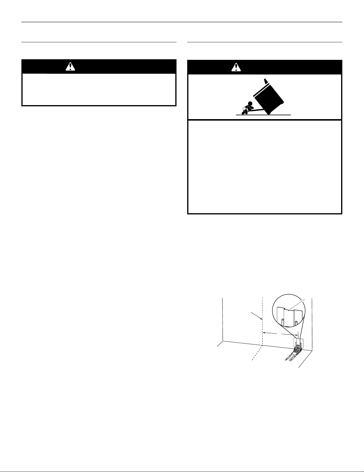
3. Determine and mark centerline of the cutout space. The
mounting bracket can be installed on either the left-hand or
right-hand side of the cutout. Position mounting bracket
against the wall in the cutout so that the V-notch of the
bracket is 12½" (31.8 cm) from centerline, as shown.
10
B
Centerline
A
A. 12½" (31.8 cm)
B. Bracket V-notch
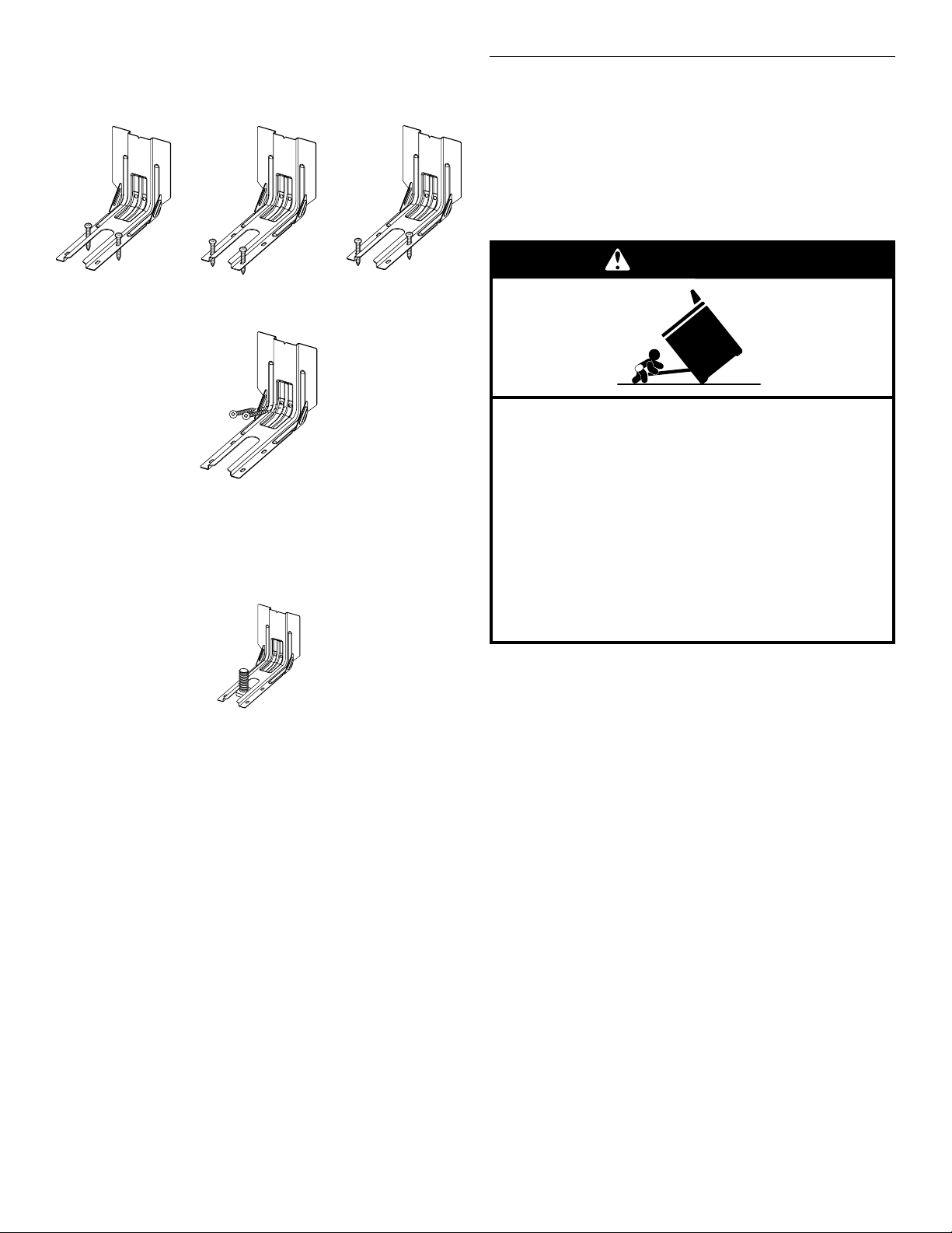
4. Drill two 1/8" (3 mm) holes that correspond to the bracket
holes of the determined mounting method. See the following
illustrations.
Floor Mounting
Rear position
Wall Mounting
5. Using the two #10 x 15/8" (4.1 cm) Phillips-head screws
provided, mount anti-tip bracket to the wall or oor.
6. Move range close enough to opening to allow for nal
electrical connections. Remove shipping base, cardboard, or
hardboard from under range.
7. Move range into its nal location, making sure rear leveling
leg slides into anti-tip bracket.
Front position
Diagonal (2 options)
Adjust Leveling Legs
1. If range height adjustment is necessary, use a wrench or
pliers to loosen the 4 leveling legs.
This may be done with the range on its back or with the
range supported on 2 legs after the range has been placed
back to a standing position.
NOTE: To place range back up into a standing position, put
a sheet of cardboard or hardboard in front of range. Using 2
or more people, stand range back up onto the cardboard or
hardboard.
WARNING
Tip Over Hazard
A child or adult can tip the range and be killed.
Install anti-tip bracket to floor or wall per installation
instructions.
Slide range back so rear range foot is engaged in the
slot of the anti-tip bracket.
Re-engage anti-tip bracket if range is moved.
Do not operate range without anti-tip bracket installed
and engaged.
Failure to follow these instructions can result in death
or serious burns to children and adults.
8. Move range forward onto shipping base, cardboard or
hardboard to continue installing the range, using the
following installation instructions.
2. Measure the distance from the top of the counter to the oor.
3. Measure the distance from the top of the cooktop to the
bottom of the leveling legs. This distance should be the
same. If it is not, adjust the leveling legs to the correct
height. The leveling legs can be loosened to add up to a
maximum of 1" (2.5 cm). A minimum of 3/16" (5 mm) is
needed to engage the anti-tip bracket.
NOTE: If height adjustment is made when range is standing,
tilt the range back to adjust the front legs, and then tilt
forward to adjust the rear legs.
11
4. When the range is at the correct height, check that there is
C. Screws (2)
A
B
C
adequate clearance under the range for the anti-tip bracket.
Before sliding range into its nal location, check that the antitip bracket will slide under the range and onto the rear
leveling leg prior to anti-tip bracket installation.
NOTE: If a Trim Kit will be used, the top of the cooktop
should be higher than the counter. See the Installation
Instructions included with the Trim Kit for the correct height.
Electrical Connection - U.S.A. Only
If your home has a 3- or 4-wire receptacle, continue with “Install
Using a Power Supply Cord”. If your home has a 3- or 4-wire
direct connection, go to “Install Using Direct Wire”.
Install Using a Power Supply Cord
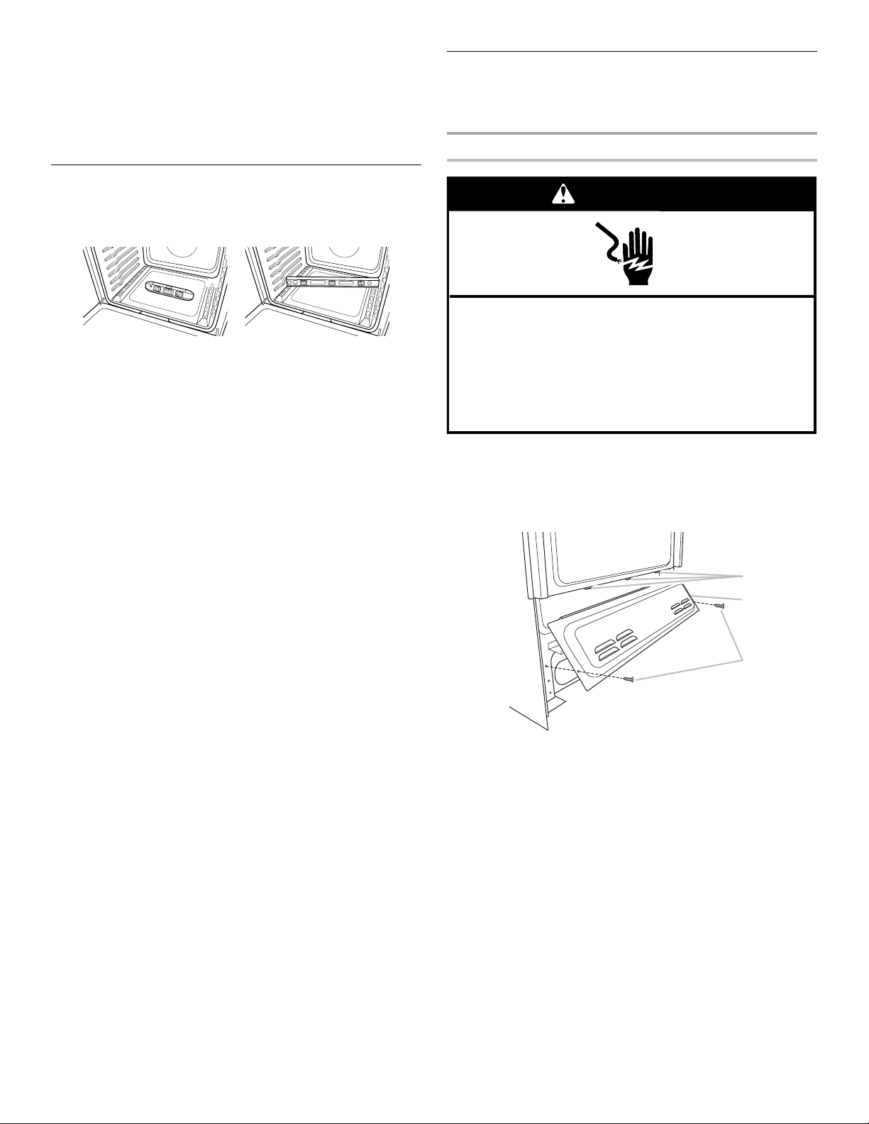
Level Range
1. Place level on the oven bottom, as indicated in one of the
two gures below, depending on the size of the level. Check
with the level side to side and front to back.
2. If range is not level, use a wrench or pliers to adjust leveling
legs up or down until the range is level.
NOTE: Range must be level for satisfactory baking
performance and best cleaning results using AquaLift®
Self-Clean Technology.
WARNING
Electrical Shock Hazard
Disconnect power before servicing.
Use a new 40 amp power supply cord.
Plug into a grounded outlet.
Failure to follow these instructions can result in death,
fire, or electrical shock.
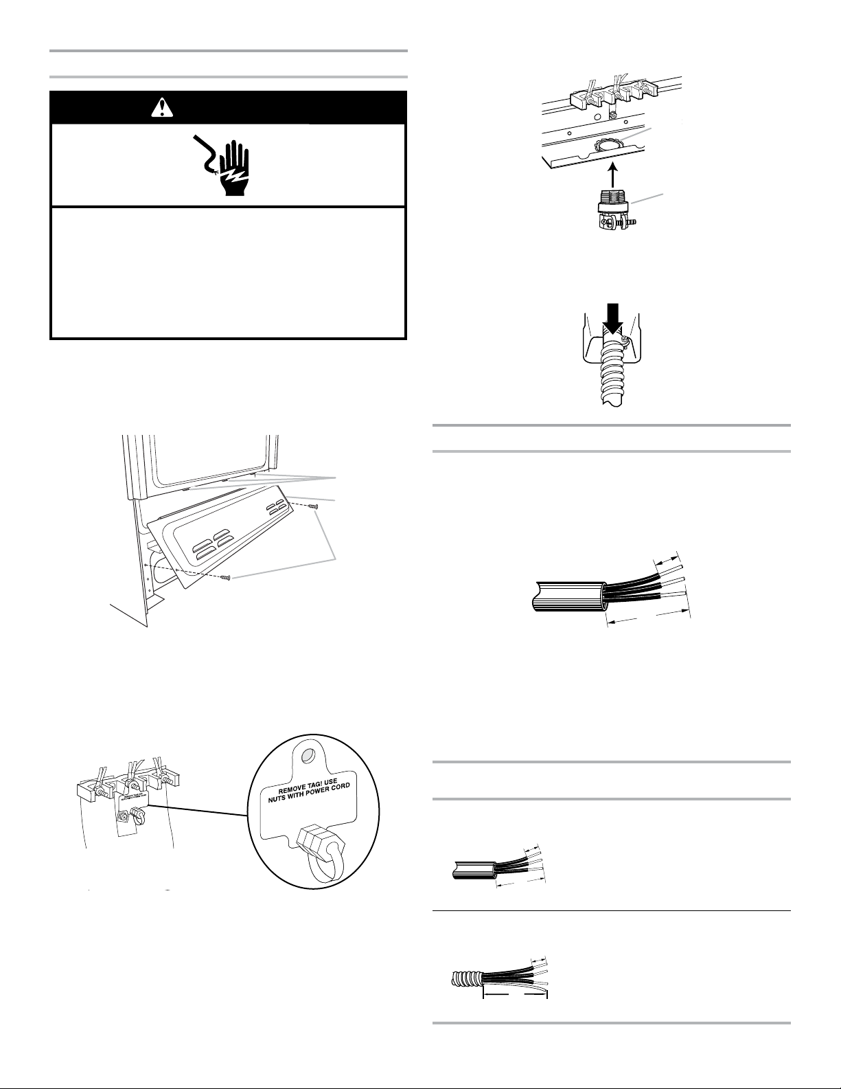
Power Supply Cord Strain Relief
1. Disconnect power.
2. Remove the lower access cover screws located on the back
of the range. Pull the bottom of the cover toward you and out
to remove cover from range.
12
A. Mounting tabs (3)
B. Lower access cover
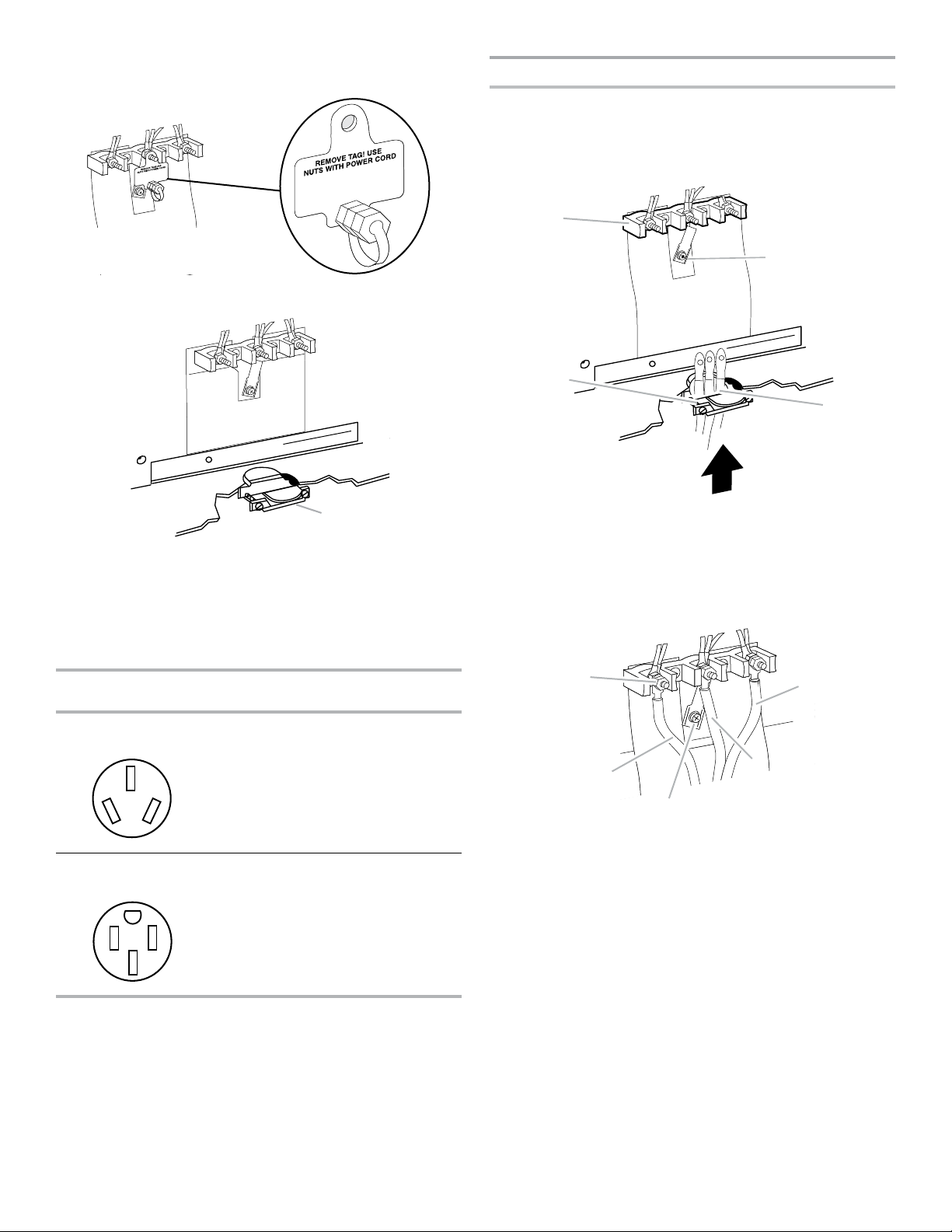
3. Remove plastic tag holding three 10-32 hex nuts from the
A. UL listed strain relief
D. Power supply cord wires - large opening
D
A
B.
C. Ground-link screw
Neutral (white) wire
A
middle post of the terminal block.
4. Assemble a UL listed strain relief in the opening.
3-Wire Connection: Power Supply Cord
Use this method only if local codes permit connecting chassis
ground conductor to neutral wire of power supply cord.
1. Feed the power supply cord through the strain relief on the
cord/conduit plate on bottom of range. Allow enough slack
to easily attach the wiring to the terminal block.
A
B
C
A
5. Complete installation following instructions for your type of
electrical connection:
4-wire (recommended)
3-wire (if 4-wire is not available)
Electrical Connection Options
If your home has: And you will be
Go to Section:
connecting to:
3-wire receptacle
(NEMA type 10-50R)
A UL listed,
250 V
3-Wire Connection:
Power Supply Cord
minimum,
40 or 50 A,
range power
supply cord
4-wire receptacle
(NEMA type 14-50R)
A UL listed,
250 V
4-Wire Connection:
Power Supply Cord
minimum,
40 or 50 A,
range power
supply cord
A. Terminal block
B. Ground-link screw
C. UL listed strain relief
2. Use 3/8" (1.0 cm) nut driver to connect the neutral (white)
wire to the center terminal block post with one of the 10-32
hex nuts.
E
B
D
C
.10–32 hex nut
Line 2 (red) wire
D.
E. Line 1 (black) wire
3. Connect line 2 (red) and line 1 (black) wires to the outer
terminal block posts with 10-32 hex nuts.
4. Firmly tighten hex nuts.
NOTE: For power supply cord replacement, use only
a power cord rated at 250 V minimum, 40 or 50 A that
is marked for use with nominal 1³⁄8" (3.5 cm) diameter
connection opening, with ring terminals and marked for use
with ranges.
5. Tighten strain relief screws.
IMPORTANT: Verify the tightness of the hex nuts.
6. Replace lower access cover.
13
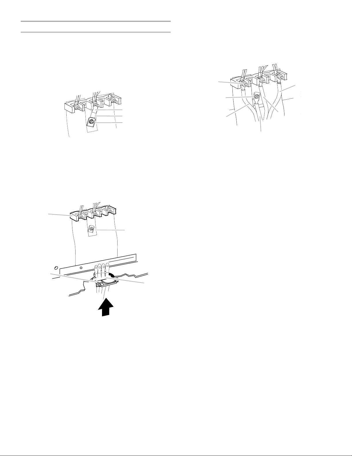
4-Wire Connection: Power Supply Cord
C. Ground-link screw
A
C
D. Power supply cord wires
A
D
A.
B.
C. Line 2 (red) wire
F. Line 1 (black) wire
A
F
Use this method for:
■ New branch-circuit installations (1996 NEC)
■ Mobile homes
■ Recreational vehicles
■ In an area where local codes prohibit grounding through the
neutral
1. Cut out and remove part of metal ground strap, as shown.
4. Use a Phillips screwdriver to connect the green ground wire
from the power supply cord to the range with the groundlink screw and ground-link section. The ground wire must be
attached over the ground-link section.
5. Use 3/8" (1.0 cm) nut driver to connect the neutral (white)
wire to the center terminal block post with one of the 10-32
hex nuts.
B
B
A. Metal ground strap
B. Discard
2. Use a Phillips screwdriver to remove the ground-link screw
from the back of the range. Save the ground-link screw and
the end of the ground link under the screw.
3. Feed the power supply cord through the strain relief on the
cord/conduit plate on bottom of range. Allow enough slack
to easily attach the wiring to the terminal block.
B
C
C
E
D
10–32 hex nut
Ground-link screw
D. Green ground wire
E. Neutral (white) wire
6. Connect line 2 (red) and line 1 (black) wires to the outer
terminal block posts with 10-32 hex nuts.
7. Firmly tighten hex nuts.
NOTE: For power supply cord replacement, use only
a power cord rated at 250 V minimum, 40 or 50 A that
is marked for use with nominal 1³⁄8" (3.5 cm) diameter
connection opening, with ring terminals and marked for use
with ranges.
8. Tighten strain relief screws.
IMPORTANT: Verify the tightness of the hex nuts.
9. Replace lower access cover.
14
A. Terminal block
B. Ground-link screw
C. UL listed strain relief
Install Using Direct Wire
C. Screws (2)
A
B
C
B. Conduit
WARNING
Electrical Shock Hazard
Disconnect power before servicing.
Use 8 gauge copper or 6 gauge aluminum wire.
Electrically ground range.
Failure to follow these instructions can result in death,
fire, or electrical shock.
Direct Wire Strain Relief
1. Disconnect power.
2. Remove the lower access cover screws located on the back
of the range. Pull the bottom of the cover toward you and out
to remove cover from range.
4. Assemble a UL listed conduit connector in the opening.
A. Removable retaining nut
5. Tighten strain relief screw against the exible conduit.
Direct Wire Installation: Copper or Aluminum Wire
A. Mounting tabs (3)
B. Lower access cover
3. Remove plastic tag holding three 10-32 hex nuts from the
middle post of the terminal block.
This range may be connected directly to the fuse disconnect or
circuit breaker box. Depending on your electrical supply, make
the required 3-wire or 4-wire connection.
1. Strip outer covering back 3" (7.6 cm) to expose wires. Strip
the insulation back 3/8" (1.0 cm) from the end of each wire.
³⁄₈"
(1.0 cm)
3"
(7.6 cm)
2. Allow enough slack in the wire to easily attach the wiring
terminal block.
3. Complete installation following instructions for your type of
electrical connection:
4-wire (recommended)
3-wire (if 4-wire is not available)
Electrical Connection Options
If your home has: And you will be
Go to Section:
connecting to:
3-wire direct A circuit breaker
³⁄₈"
(1.0 cm)
box or fused
disconnect
3-Wire Connection:
Direct Wire
3"
(7.6 cm)
4-wire direct A circuit breaker
³⁄₈"
(1.0 cm)
5"
(12.7 cm)
box or fused
disconnect
4-Wire Connection:
Direct Wire
15
 Loading...