

Page 1

Instruction Book
Page 2

Page 3

IMPORTANT SAFETY INSTRUCTIONS
When using an electrical appliance, basic safety precautions should always be followed, including the
following:
This sewing machine is designed and manufactured for household use only.
Read all instructions before using this sewing machine.
To reduce the risk of electric shock:
DANGER
1. An appliance should never be left unattended when plugged in. Always unplug
this sewing machine from the electric outlet immediately after using and before
cleaning.
WARNING
1. Do not allow to be used as a toy. Close attention is necessary when this sewing machine is used
by or near children.
2. Use this appliance only for its intended use as described in this owner’s manual.
Use only attachments recommended by the manufacturer as contained in this owner’s manual.
3. Never operate this sewing machine if it has a damaged cord or plug, if it is not working properly, if
it has been dropped or damaged, or dropped into water.
Return this sewing machine to the nearest authorized dealer or service center for examination,
repair, electrical or mechanical adjustment.
4. Never operate the appliance with any air opening blocked. Keep ventilation openings of this
sewing machine and foot controller free from accumulation of lint, dust and loose cloth.
5. Never drop or insert any object into any opening.
6. Do not use outdoors.
7. Do not operate where aerosol (spray) products are being used or where oxygen is being
administered.
8. To disconnect, turn all controls to the off (“O”) position, then remove plug from outlet.
9. Do not unplug by pulling on cord. To unplug, grasp the plug, not the cord.
10. Keep fingers away from all moving parts. Special care is required around the sewing machine
needle and/or cutting blade.
11. Always use the proper needle plate. The wrong plate can cause the needle to break.
12. Do not use bent needles.
13. Do not pull or push fabric while stitching. It may deflect the needle causing it to break.
14. Switch this sewing machine off (“O”) when making any adjustment in the needle area, such as
threading the needle, changing the needle, threading the bobbin or changing the presser foot, and
the like.
15. Always unplug this sewing machine from the electrical outlet when removing covers, lubricating, or
when making any other adjustments mentioned in this owner’s manual.
—
—
To reduce the risk of burns, fire, electric shock, or injury to persons:
SAVE THESE INSTRUCTIONS
For Europe only:
This appliance can be used by children aged from 8 years and above and persons with reduced
physical, sensory or mental capabilities or lack of experience and knowledge if they have been given
supervision or instruction concerning use of the appliance in a safe way and understand the hazards
involved. Children shall not play with the appliance. Cleaning and user maintenance shall not be made
by children without supervision.
For outside Europe (except U.S.A and Canada):
This appliance is not intended for use by persons (including children) with reduced physical, sensory or
mental capabilities, or lack of experience and knowledge, unless they have been given supervision or
instruction concerning use of the appliance by a person responsible for their safety.
Children should be supervised to ensure that they do not play with the appliance.
Please note that on disposal, this product must be safely recycled in accordance with relevant
National legislation relating to electrical/electronic products. If in doubt please contact your
retailer for guidance. (European Union only)
I
Page 4

GROUNDING INSTRUCTIONS
This product must be grounded. In the event of malfunction or breakdown, grounding provides a path of least
resistance for electric current to reduce the risk of electric shock.
This product is equipped with a cord having an equipment grounding conductor and a grounding plug.
The plug must be plugged into an appropriate outlet that is properly installed and grounded in accordance with
all local codes and ordinances.
DANGER Improper connection of the equipment-grounding conductor can result in a risk of
electric shock.
1. The conductor with insulation having an outer surface that is green with or without yellow stripes is the
equipment-grounding conductor.
2. If repair or replacement of the cord or plug is necessary, do not connect the equipment-grounding
conductor to a live terminal.
3. Check with a qualified electrician or serviceman if the grounding instructions are not completely
understood, or if in doubt as to whether the product is properly grounded.
Do not modify the plug provided with the product if it will not fit the outlet, have a proper outlet installed by
a qualified electrician.
4. This product is for use on a nominal 120 V circuit, and has a grounding plug that looks like the plug illustrated
in Fig. A. A temporary adaptor, which looks like the adaptor illustrated in Fig. C, may be used to connect this
plug to a 2-pole receptacle as shown in Fig B. If a properly grounded outlet is not available, the temporary
adapter should be used only until a properly grounded outlet can be installed by a qualified electrician.
The green colored rigid ear, lug, and the like, extending from the adaptor must be connected to a permanent
ground such as a properly grounded outlet box cover. Whenever the adaptor is used, it must be held in place
by the metal screw.
Fig. A
Fig.C
Fig.B
grounding means
Fig.C
Metal screw
II
Page 5

TABLE OF CONTENTS
SETTING UP THE MACHINE
Installing the Machine ...................................................... 2
Adjusting the feet ........................................................... 3
Names of Parts ................................................................ 5
Sub control panel ..........................................................6
RCS unit (optional for some models) ............................6
Standard Accessories .................................................7-8
Assembling the Spool Stand ...........................................9
Setting the Thread Cones or Spools of Thread ............. 10
Setting the spool of thread ..........................................10
Setting the thread cone ...............................................10
Installing the Hoop Supporter ........................................ 11
Installing the RCS Unit (optional for some models) ....... 12
Connecting the Power Supply ....................................... 13
Direct PC-Link ...............................................................14
Winding the Bobbin .......................................................15
Removing the bobbin case .......................................... 16
Removing the bobbin ..................................................16
Inserting the bobbin ..................................................... 17
Inserting the bobbin case ............................................17
Threading the Needle ...............................................18-20
Threading the needle with the needle threader ........... 20
Stabilizers ...................................................................... 21
Template ........................................................................ 21
Setting the Fabric in the Embroidery Hoop....................22
Setting the Embroidery Hoop ........................................23
Adjusting the Hoop Supporter for Optional Hoops ........23
BASIC OPERATION
Basic Operation with the Sub Control Panel .................24
Machine operating buttons .......................................... 24
Function buttons .......................................................... 24
LCD screen .................................................................25
Machine setting ........................................................26-27
Starting to Embroider................................................28-29
Removing the Hoop ....................................................... 30
Adjusting the Thread Tension ........................................ 31
Replacing the needle ..................................................... 32
Basic Operation of the Optional RCS Unit.....................33
Machine operating buttons .......................................... 33
Panel keys ................................................................... 34
On-screen Help Movie ................................................... 35
Disconnecting the RCS Unit .......................................... 36
Moving the pattern ....................................................... 50
Resizing the pattern ....................................................50
Rotating the pattern ..................................................... 51
Deleting the pattern ..................................................... 51
Saving the le .............................................................. 51
Alternate function key assignment ..............................52
Duplicating the pattern ................................................52
Flipping the pattern ...................................................... 52
Monogramming in an arc ............................................. 53
Customizing the color setting ......................................54
Grouping the patterns .................................................... 55
Color grouping ............................................................. 55
Zooming the editing window .......................................... 56
Combining the Patterns and Lettering ......................57-59
Adjusting the start position ............................................60
Adjusting the re-start position after thread breakage.....60
Starting to Embroider.....................................................61
Customizing the Settings with the
Sub Control Panel ....................................................62-66
Customizing the Settings with the Optional
RCS Unit...................................................................67-77
File Management ........................................................... 78
Saving the Pattern as a File ........................................78
Creating a new folder ..................................................79
Changing the folder name ........................................... 79
Opening a le ..............................................................80
File list option ..............................................................81
Deleting the folder .......................................................82
Deleting the le ............................................................ 82
OPTIONAL ITEMS
USB Flash Drive ............................................................ 83
CARE AND MAINTENANCE
Cleaning the Hook ......................................................... 84
Cleaning the Bobbin Case ............................................. 84
Cleaning the Tension Leaves and Disks ........................ 85
Cleaning the Auto Thread Cutter Mechanism ................ 86
Oiling ........................................................................87-88
Error Message ............................................................... 89
Troubleshooting ........................................................90-91
ADVANCED OPERATION WITH THE OPTIONAL
RCS UNIT
Selecting the Embroidery Patterns ................................ 37
Selecting the built-in designs ..................................38-39
Function keys ...........................................................40-41
Monogramming..............................................................42
Function keys ..............................................................43
Entering the characters ...............................................44
Deleting a character ....................................................45
Inserting a character .................................................... 45
Saving the monogram .................................................45
Placement of monogramming .....................................46
Multi-color monogramming .......................................... 47
Editing............................................................................48
Editing Functions ........................................................... 49
Selecting the hoop .......................................................49
1
Page 6
SETTING UP THE MACHINE
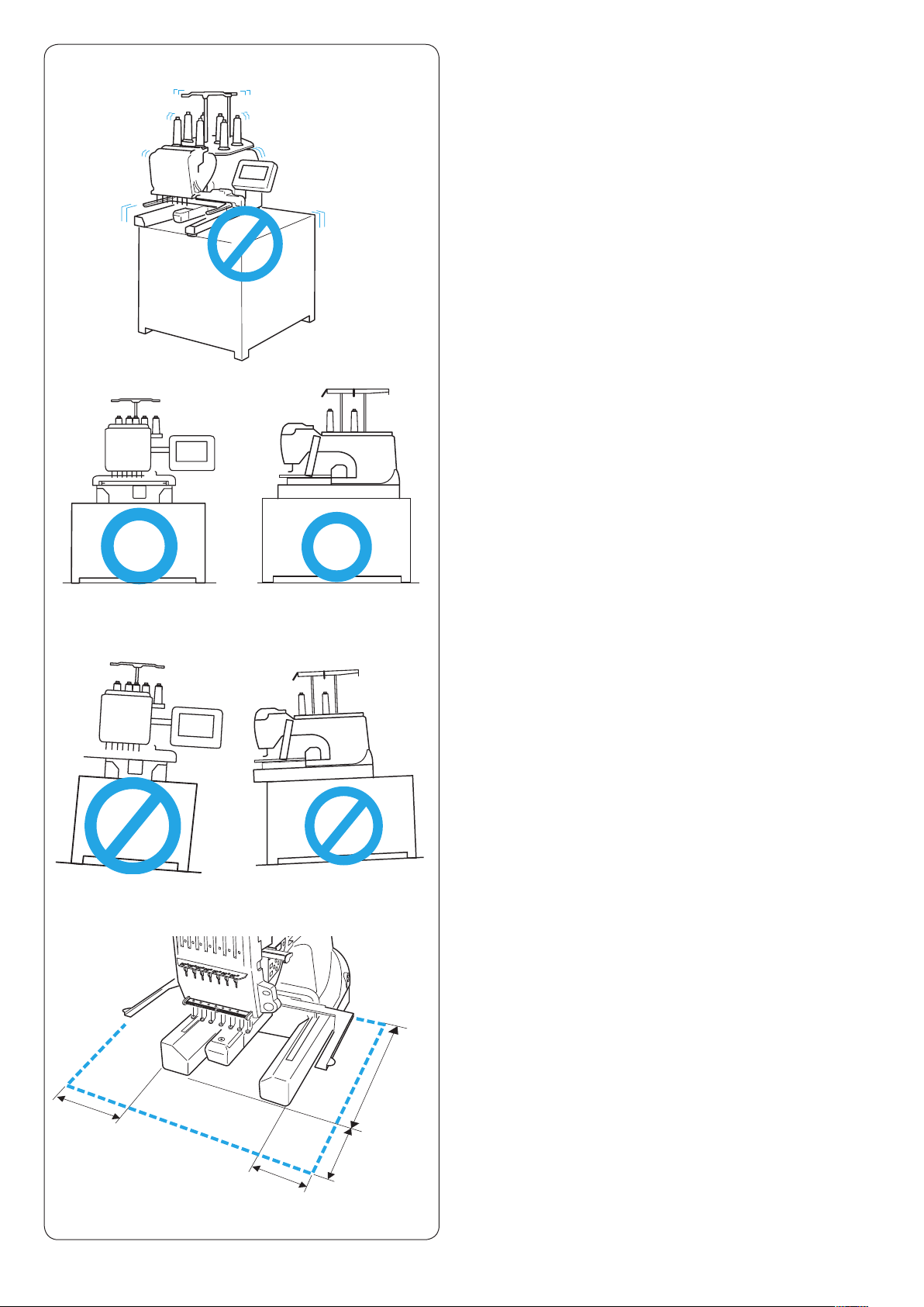
Installing the Machine
Place the machine on a at and stable surface such as
a sturdy table that could withstand the machine’s weight
and vibration.
Place the machine on the at and level surface.
Make sure that all the feet rmly contact the surface.
q
Provide a sufcient space around the machine to
allow the hoop to move freely.
q 20 cm (7–7/8˝)
w 20 cm (7–7/8˝)
e 30 cm (11–7/8˝)
e
w
q
2
Page 7
e
e
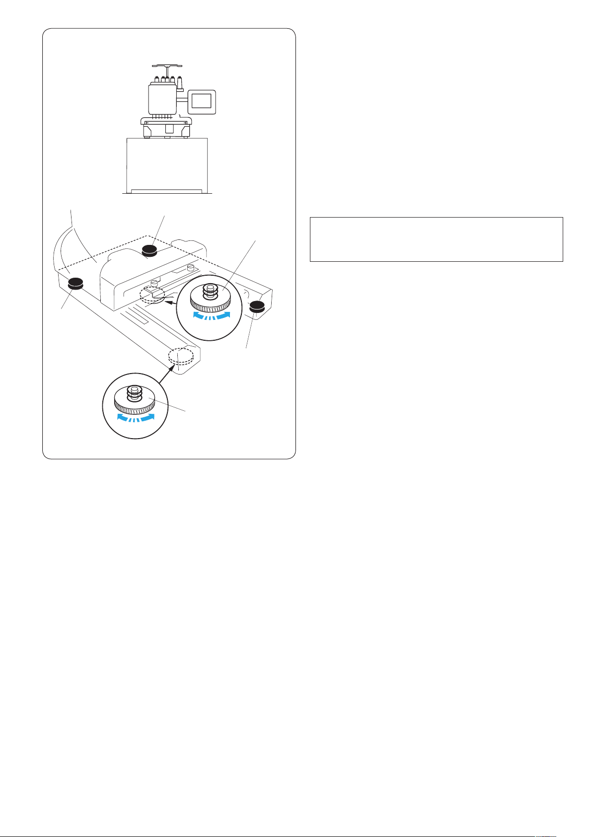
Adjusting the feet
Turn the adjusting screw counterclockwise (in the
direction of A) as much as possible, before placing the
machine on a surface.
q Adjusting screw
Place the machine on a at and level surface.
Turn the adjustable foot so the four feet rmly contact the
surface.
w Adjustable foot
e Foot
Turn the adjusting screw clockwise (in the direction B)
until it contacts the surface.
q
B
A
NOTE:
Make sure that the machine sits on the surface without
shaking.
w
e
3
Page 8

CAUTION:
Do not use the machine near appliances that radiate
electromagnetic noise such as a microwave oven, or
do not plug in the machine to the same branch circuit
where such appliances are connected.
CAUTION:
Do not use or store the machine near a heat radiator
or in a place with dust or high humidity.
CAUTION:
Do not expose the machine to direct sunlight or open
air.
CAUTION:
Two or more persons are required when transporting
the machine.
Hold the machine by the two legs and the hand grip
on the bottom of the backside of the machine.
q Hand grip
* Remove the hoop supporter when transporting the
machine to avoid damage by hitting the supporter.
q
4
Page 9
e
q
w
!1
!2
!0
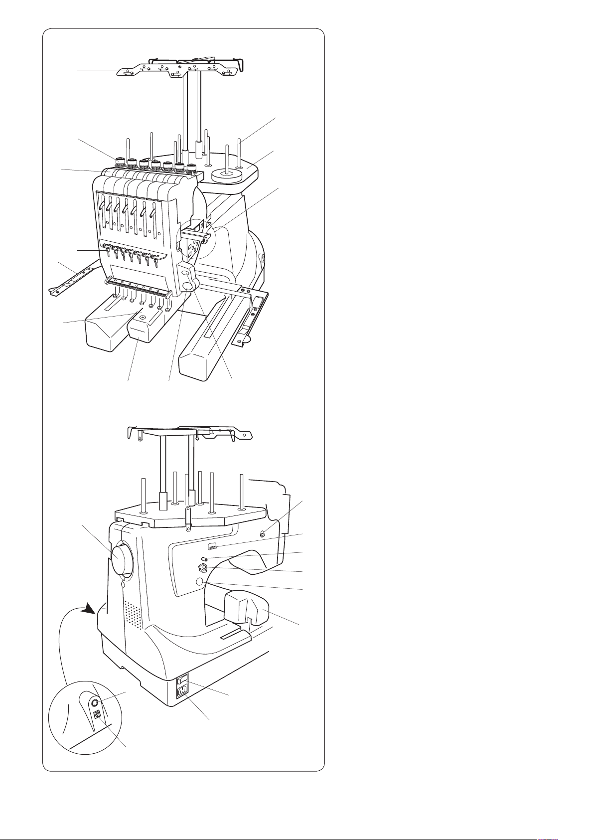
Names of Parts
Thread guide bar
q
Pre-tension control
w
Tension control
e
Check spring
r
Hoop supporter
t
Needle plate
y
Hook cover
u
START/STOP button
i
Auto thread cutter button
o
Sub control panel
!0
Spool stand
!1
Spool pins
!2
t
y
r
@1
u
i
o
@0
!9
!8
!7
!6
* For assembling the thread guide bar and the
spool stand, refer to page 9.
*
For installing the hoop supporter, refer to page 11.
Machine socket
!3
Power switch
!4
Carriage
!5
Bobbin winder button
!6
Bobbin winder stopper
!7
Bobbin winder spindle
!8
Bobbin thread cutter
!9
Bobbin winder thread guide
@0
Handwheel
@1
RCS connector socket
@2
USB port
@3
@2
@3
!5
!4
!3
5
Page 10

q
w
y
e
r
t
q
Sub control panel
MODE button
q
Trace button
w
Arrow buttons
e
ENTER button
r
LCD brightness adjusting dial
t
LCD display
y
RCS unit (optional for some models)
RCS unit
q
START/STOP button
w
Auto thread cutter button
e
Trace button
r
Jog buttons
t
Carriage return button
y
Stitch back button
u
Stitch forward button
i
Bobbin winder button
o
Bobbin winder indicator
!0
USB port
!1
LCD touch panel
!2
w
e
r
!2
t
y
u
i
* The RCS unit is for 7-needle embroidery machine only
and cannot be used for other models.
!0
!1
o
CAUTION:
Do not press the LCD touch panel with hard or sharp
pointed objects like pencils, screwdrivers or the like.
Press the LCD touch panel and buttons gently.
Rough or forceful pressing may damage the unit.
6
Page 11

q w
e r
t y
u
Standard Accessories
Needle (DB x K5Q1-NY, #11) (x 10)
q
Scissors
w
Bobbin (x 5)
e
Lint brush
r
Seam ripper
t
Handy needle threader
y
Spool cap (x 8)
u
Spool net (x 15)
i
Screwdriver
o
Screwdriver (small)
!0
Oiler
!1
Tweezers
!2
Offset screwdriver
!3
Accessory box
!4
i
o !0
!1
!3
!2
!4
7
Page 12

y
i
r
t
w
u
Standard Accessories
Instruction book
eq
q
Instructional DVD
w
Power supply cable
e
USB cable
r
Screwdriver (large)
t
Hoop M1
y
(with template)
Hoop M2
u
(with template)
Hoop M3 (MB Hoop 50 x 50
i
(with template)
Hoop supporter
o
Felt ring (large) (x 8)
!0
Felt ring (small) (x 8)
!1
Spool rest (x 8)
!2
Thread guide bar
!3
Spool stand
!4
Thread guide pole (x 2)
!5
Setscrew (x 3)
!6
Setscrew A (x 2)
!7
Setscrew B (x 2)
!8
Spool pin A (x 7)
!9
Spool pin B (x 1)
@0
(MB Hoop 240 x 200 mm)
(MB Hoop 126 x 110 mm)
mm
)
o
!0
!1
!3
!4
!6
!2
!5
RCS unit (optional for some models)
!9
@0
!7 !8
8
Page 13
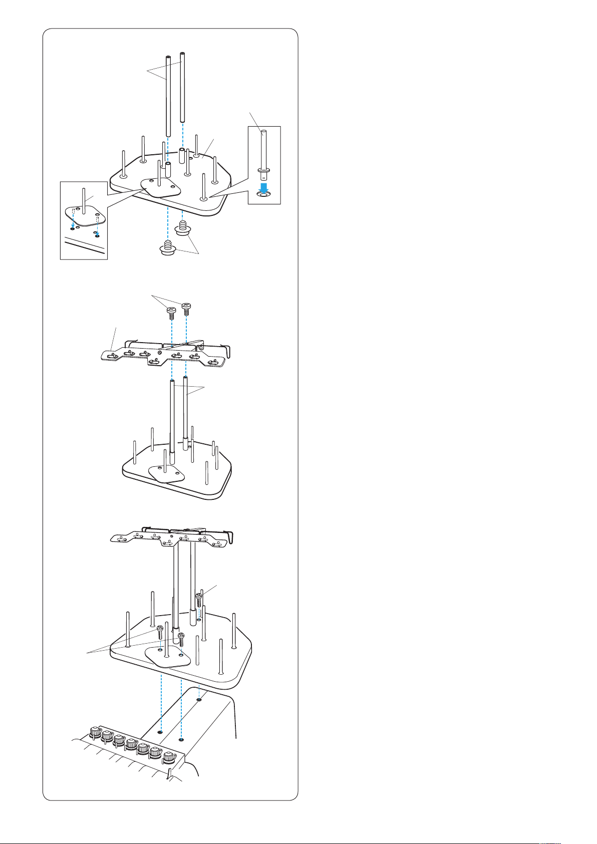
Assembling the Spool Stand
z x
c
t
y
q
u
w
e
r
z Insert the spool pins A into the spool stand.
Insert the thread guide poles and secure the poles
with setscrews A from the bottom.
q Thread guide poles
w Setscrews A
e Spool stand
r Spool pin A
x Insert the spool pin B into the spool stand.
t Spool pin B
c Attach the thread guide bar to the thread guide poles
with the setscrews B.
* Tighten the setscrews rmly with the screwdriver
(large).
y Thread guide bar
u Setscrews B
v
q
v Attach the assembled spool stand to the machine with
the 3 setscrews.
i Setscrews
i
i
9
Page 14

e
w
e
y
q
t
r
w
e
Setting the Thread Cones or Spools of Thread
Felt rings of two sizes are provided to accommodate
various types of spools of thread and thread cones.
Use the large felt rings for large thread cones.
For small thread cones or spools of thread, insert the
small felt rings into the large rings.
q Spool of thread
w Spool pin
e Felt ring (large)
r Felt ring (small)
t Small spool of thread
y Spool pin for bobbin winding
w
w
i
q
u
o
Setting the spool of thread
Place the spool of thread on the spool pin, with the thread
coming out from the left backside.
Attach the spool cap and rmly press it against the spool.
w Spool pin
u Spool cap
Setting the thread cone
Attach the spool rests on the spool pins.
Place the thread cones on the spool pins.
Cover the thread cone with the spool net if the thread is
shaky or kinky when sewing.
If the net is too long for a spool, fold the net and place it
on the spool.
q Spool of thread
w Spool pin
i Spool rest
o Spool net
!0
NOTE:
To prevent the thread from unraveling, leave the net on
the thread cone or hook the thread end into the notch
of the spool when it is not in use.
!0 Notch
10
Page 15
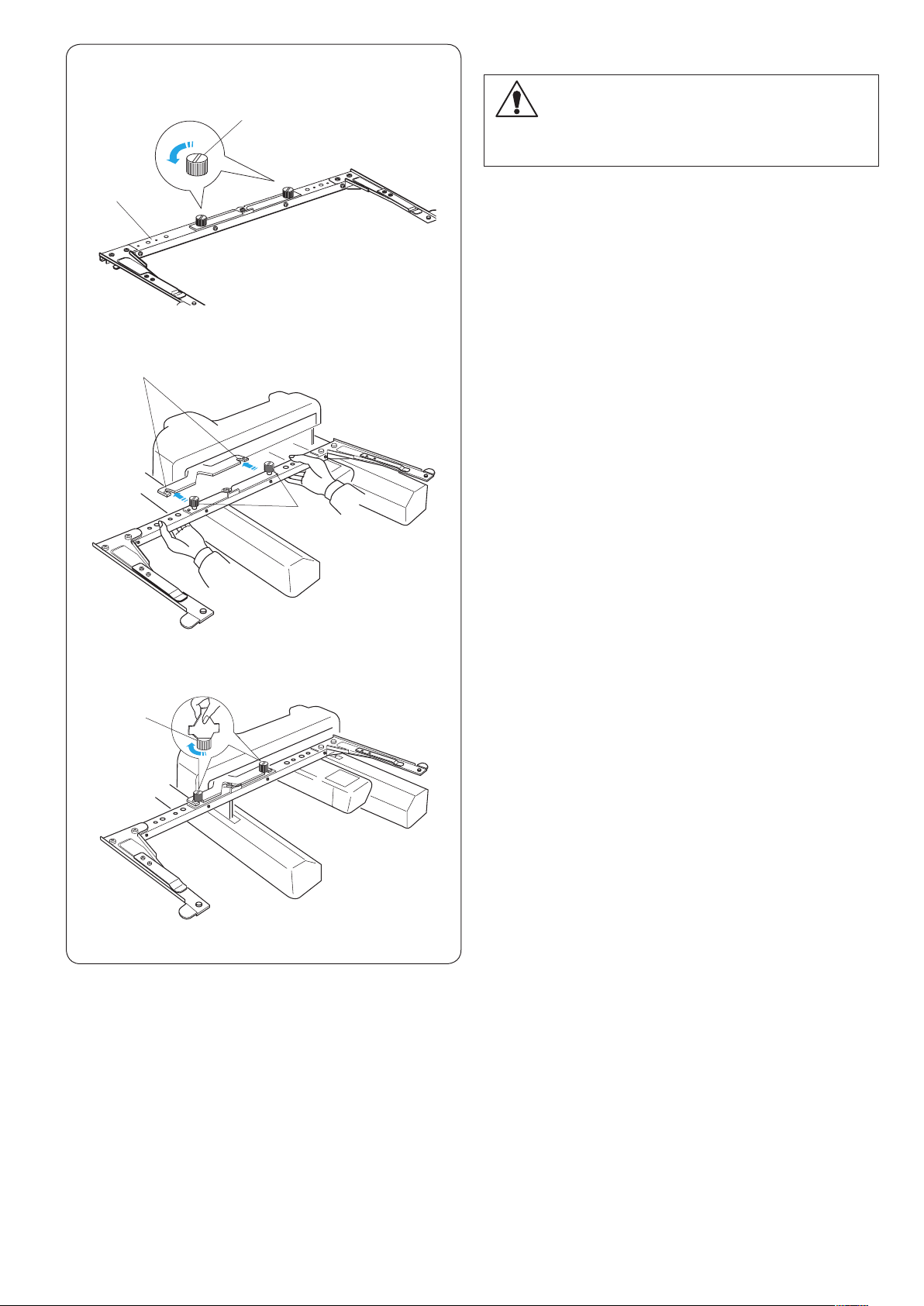
Installing the Hoop Supporter
z
x
q
e
w
CAUTION:
Turn the power switch off before installing the hoop
supporter.
z Loosen the two thumbscrews on the hoop supporter.
q Hoop supporter
w Thumbscrew
x Hold the hoop supporter with both hands and place it
under the carriage plate by inserting the necks of both
thumbscrews into the slots in the carriage plate.
e Slot in the carriage plate
w
c
w
c Tighten the thumbscrews with the screwdriver to
secure the hoop supporter.
* When carrying the machine, remove the hoop supporter
from the machine.
11
Page 16
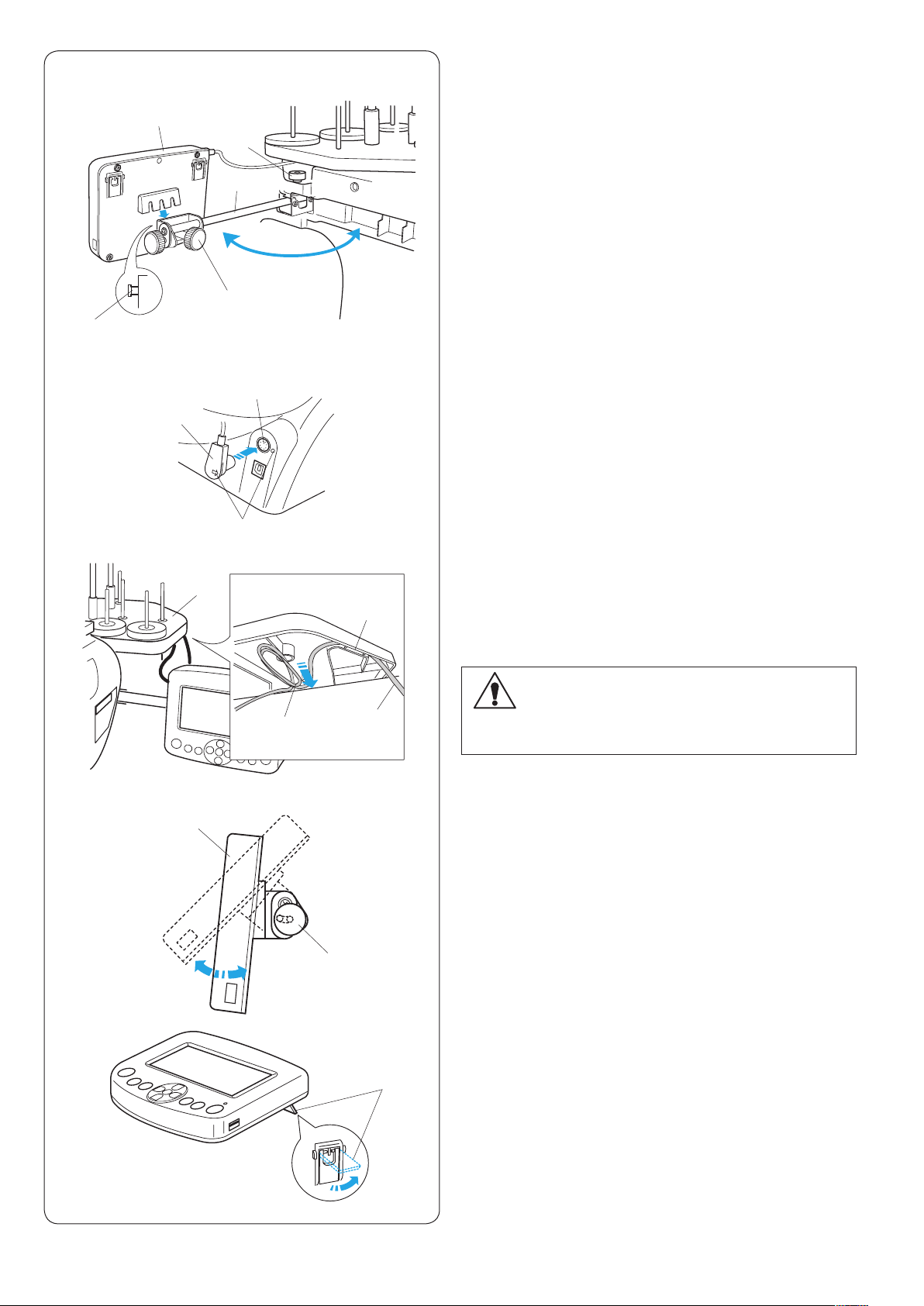
Installing the RCS Unit (optional for some models)
z x c
t
v
b
r
u
o
q
w
e
y
i
View from the bottom
!0
z Loosen the thumbscrew and open the mounting arm.
q Thumbscrew
w Mounting arm
x Loosen the screw knob A and set the RCS unit on the
mounting arm by hooking the RCS unit on the pins.
Tighten the screw knob A to secure the RCS unit.
e Screw knob A
r RCS unit
t Pin
c Adjust the angle of the mounting arm as desired and
tighten the thumbscrew.
q Thumbscrew
w Mounting arm
v Insert the connector into the connector socket on the
back of the machine with the marks aligned.
y Connector socket
u Connector
i Mark
b Fold and secure the cable under the spool stand as
shown.
o Spool stand
!0 Cable slotted into ribs
!1 Cable coming from connector
!2 Excess cable secured in the opening
n m
r
!2
!3
!1
!4
CAUTION:
Make sure to secure the cable under the spool stand.
A loose cable may interfere with the hoop.
n Loosen the screw knob B on the end of the mounting
arm and tilt the RCS unit to adjust the angle of the
LCD screen for easier viewing.
m Tighten the screw knob B to secure the RCS unit.
r RCS unit
!3 Screw knob B
If you want to use the RCS unit without installing, extend
the two legs on the backside of the RCS unit so that it
rests on an angle for easier viewing.
!4 Leg
12
Page 17

z
v
q
e
x
w
r
c
t
Connecting the Power Supply
CAUTION:
Turn the power switch off before connecting the
machine to the power supply.
z Turn the power switch off.
q Power switch
x Insert the machine plug into the machine socket.
w Machine plug
e Machine socket
c Insert the power supply plug into the properly
grounded outlet.
r Power supply plug
t Wall outlet (grounded)
v Turn the power switch on.
q Power switch
CAUTION:
While in operation, always keep your eyes on
thevsewing area, and do not touch any moving parts
such as the thread take-up lever, handwheel or
needle.
Always turn off the power switch and unplug the
machine from the power supply:
- when leaving the machine unattended.
- when attaching or removing parts.
- when cleaning the machine.
Grounding Instructions:
This machine is equipped with a grounding cable and
plug.
The plug must be plugged into an appropriate outlet that
is properly installed and grounded.
If a properly grounded outlet is not available, contact
a qualied electrician to install the properly grounded
outlet.
Refer to page II for more instructions.
13
Page 18

PC
M
q
w
Direct PC-Link
The machine can be connected to PC with the USB cable
included as standard accessory.
You need Digitizer V5 software (optional item) to operate
the machine via direct PC-link.
q Type A USB connector
w Type B USB connector
e Transferring the data
Connecting the Machine and PC
Start up the machine and PC, and insert the type A USB
connector into the PC.
Insert the type B USB connector into the USB port on the
machine.
For operating instructions, refer to the instruction manual
of Digitizer V5.
CAUTION:
Do not turn the power switch off or disconnect the
USB cable while the data transfer is in progress.
Otherwise the data will be lost or the memory will be
damaged.
e
Embroidery Data Format
The following embroidery data formats can be used
with this machine.
(1) .jef (Janome embroidery format)
(2) .jef + (editable Janome embroidery format)
(3) .dst (Tajima embroidery format)
* Tajima format (.dst) does not have thread color
information. Madeira (Rayon 40) thread color
information will be assigned automatically.
14
Page 19

Winding the Bobbin
z x
q
t
c
u
y
w
e
NOTE:
Cotton or spun polyester threads sizes 90 to 120 are
recommended for bobbin thread.
Do not use poor quality prewound bobbins.
z Place the thread cone (spool of thread) on the rear
most spool pin.
x Pass the thread through the thread guide A.
Pass the thread through the upper hole and lower hole
in the thread guide B.
q Thread guide A
w Thread guide B
e
c Draw the thread to the front.
Hold the thread with both hands and pass the thread
rmly around and under the tension disk.
e Tension disk
v b
t
r
n
u
,
t
m
u
y
v Pass the thread through the hole in the bobbin from
the inside.
Put the bobbin on the bobbin winder spindle.
r Hole in the bobbin
t Bobbin winder spindle
b Push the bobbin winder stopper up against the
bobbin.
y Bobbin winder stopper
n Press the bobbin winding button while holding the
thread end.
u Bobbin winder button
m Press the bobbin winder button to stop the machine
when the bobbin has wound a few layers.
Cut the thread close to the bobbin and press the
bobbin winder button again.
u Bobbin winder button
, When the bobbin is fully wound, the machine will stop
automatically.
Remove the bobbin from the bobbin winder spindle.
t Bobbin winder spindle
i
Cut the thread with the bobbin thread cutter.
i Bobbin thread cutter
* Do not remove the thread from the bobbin thread
cutter after cutting the thread.
15
Page 20
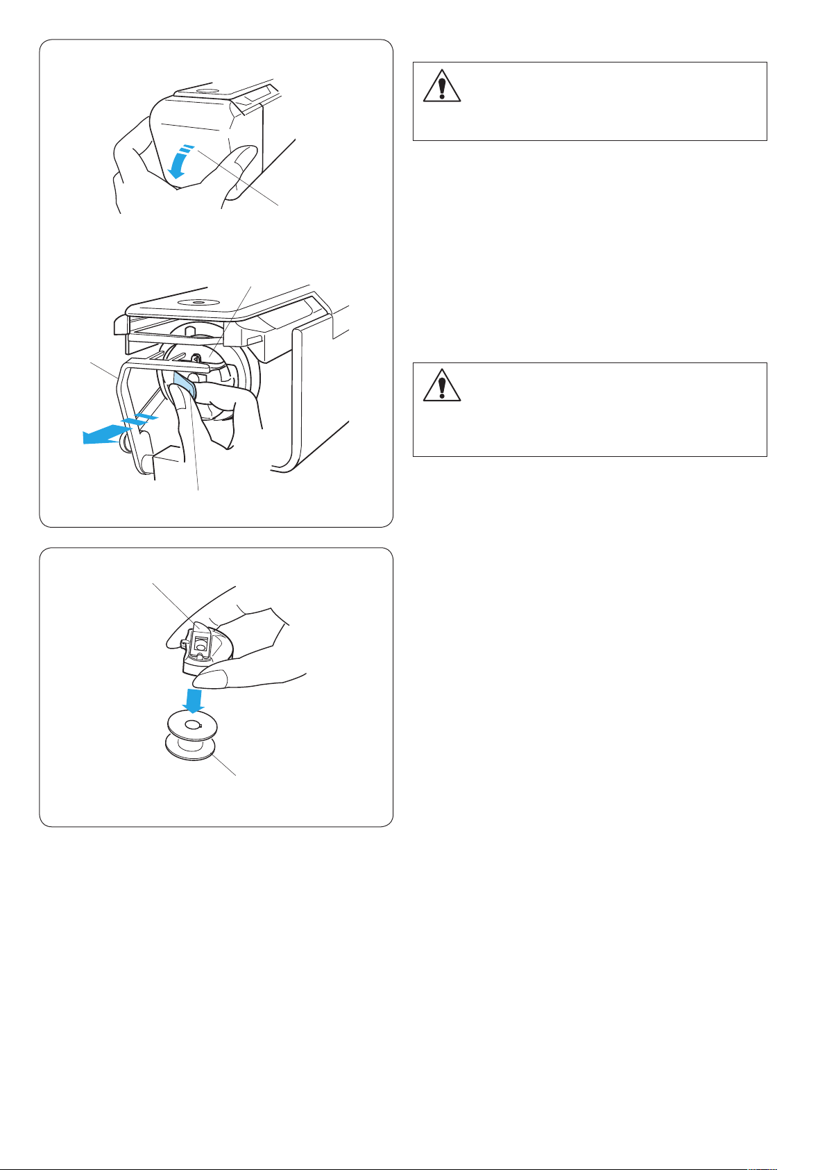
Removing the bobbin case
z
x
r
w
CAUTION:
Turn the power switch off before removing the bobbin
case.
z Open the hook cover toward you.
q Hook cover
q
x Hold and open the latch of the bobbin case.
Take the bobbin case out from the machine.
w Bobbin case
e Latch
CAUTION:
Do not force to pull the thread keeper when you
remove the bobbin case.
r Thread keeper
q
e
Removing the bobbin
Release the latch and take out the bobbin.
q Latch
w Bobbin
w
16
Page 21
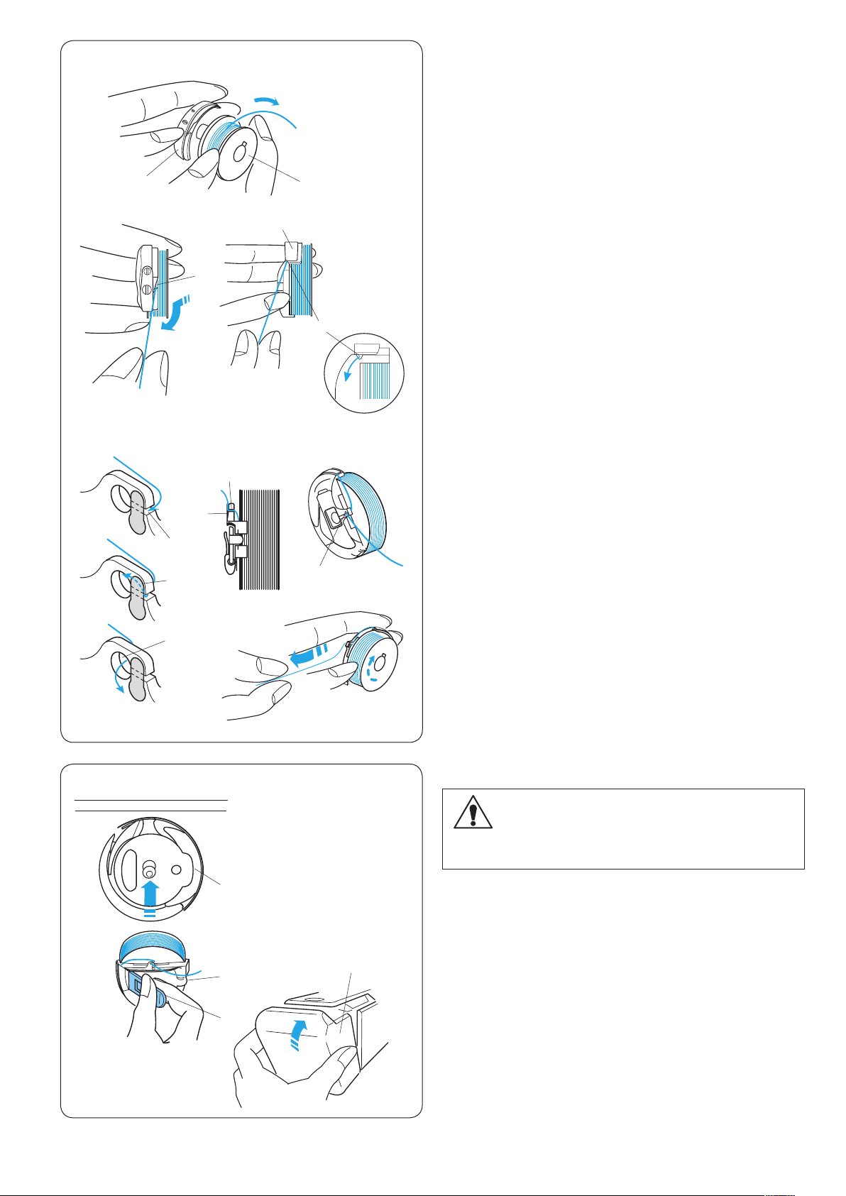
Inserting the bobbin
z
w
x c
e
v
y
u
r
q
t
z Insert the bobbin into the bobbin case leaving a
2˝ (5 cm) thread tail as illustrated.
q Bobbin
w Bobbin case
x Draw the thread to slip it into the slit of the bobbin
case.
e Slit
c Pull the thread to slide it under the tension blade until
the thread comes out from the notch.
r Tension blade
t Notch
v Draw the thread to the right behind the thread guide
and slip the thread into the back slit.
y Back slit
u Spring
i Front hole
z
y
u
i
e
w
x
i
r
* The bobbin should turn clockwise when the thread
is pulled.
* Pull out about 2˝ (5 cm) of thread.
Inserting the bobbin case
CAUTION:
Turn the power switch off before inserting the bobbin
case.
z Hold the bobbin case with the latch and insert the
bobbin case into the hook, aligning the bulge with the
concave. Push the bobbin case as far as it will go and
release the latch.
q Latch
w Bulge
e Concave
q
x Close the hook cover.
r Hook cover
17
Page 22
z x
q
w
e
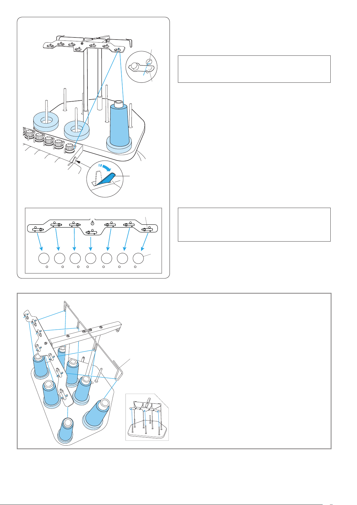
Threading the Needle
The method of threading needle is all similar.
Review the threading procedure of the rst needle when
threading other needles.
NOTE:
Rayon threads are recommended for needles to
achieve a better result.
Threading needle No.1
z Push back the tension release lever.
q Tension release lever
x Place a thread cone on the front right spool pin.
Draw the thread up and pass it through the right hole
in the thread guide bar from behind.
Slip the thread under the tension leaf.
w Hole in the thread guide bar
e Tension leaf
e
NOTE:
Refer to the illustration for the thread path of each
pre-tension.
r Pre-tension
r
Threading needles No. 2-7
For threading needles No. 4 and 7, draw the thread up
and pass it through the hole in the thread guide bar
from behind.
For threading needles No. 2, 3, 5 and 6, pass the
thread through the thread guide and pass is through
the hole in the thread guide bar from behind.
6
7
5
t
t Thread guide
Slip the thread under the tension leaf as illustrated.
4
3
y
* The number on thread cone indicates the needle
number.
y Threading path
2
1
18
Page 23

c
v
c Draw the thread to the right pre-tension control.
t
r
u
r
u
t
y
u
i
Pass the thread through the guide hole from behind.
While holding the thread with both hands, slip the
thread under the tension disk of the pre-tension
control.
Hook the thread around the guide pin from right to left
as shown in the threading path.
Make sure to insert the thread under the tension disk
by tugging the thread.
r Pre-tension control
t Guide hole
y Threading path
u Guide pin
v Hold the thread with both hands and pull it down along
the right channel.
i Tension control
b n m , .
⁄0 ⁄1 ⁄2
!3
!4
!6
!2
!0
o
!1
!5
!7
!8
b Draw the thread down and pass it through the right
hole in the guide plate.
o Guide plate
!0 Right hole in the guide plate
n Pass the thread through the eye of the right check
spring.
!1 Eye of the check spring
m Pull the thread up and pass it through the second hole
from the right.
!2 Second hole from the right
, Continue to pull the thread up to the right take-up
lever. Pass the thread through the eye of the take-up
lever.
!3 Take-up lever
. Draw the thread down and pass it through the third
hole from the right in the guide plate.
!4 Third hole from the right
⁄0 Continue to draw the thread down to the lower guide
plate and pass the thread through the right hole.
!5 Lower guide plate
!6 Right hole in the lower guide plate
⁄1 Hold the thread with both hand and slip the thread
behind in the right needle bar thread guide.
!7 Needle bar thread guide
⁄2 Thread the needle with the handy needle threader
(refer to the next page).
!8 Needle
19
Page 24

⁄3
⁄3 Pass the thread through the hole in the presser foot.
Draw the thread up and pinch the thread tail with the
holder spring.
!9 Hole in the presser foot
@0 Holder spring
@0
!9
⁄4
z
x
q
w
e
q
⁄4 Pull up the tension release lever to close the tension
disks.
q Tension release lever
Threading the needle with the needle threader
z Hold the needle threader with a triangle mark facing
up. Insert the thread into the Y-notch of the threader
from the right.
q Triangle mark
w Y- n o t c h
x Slide the threader down along the needle while
pushing it gently until the threader pin goes into the
needle eye.
Place the V-notch over the needle just above the
needle eye.
e V-notch
c
v
r
c Push the threader until the threader pin comes out
through the needle eye with a loop of thread.
v Remove the threader from the needle slowly, leaving
the thread loop behind the needle eye.
Using the tweezers, pull the loop of the thread out to
the back.
r Tweezers
20
Page 25

q
Adhesive (Iron-on) Stabilizer
Place the Wrong side of fabric and the glossy side of the
stabilizer together. Fold up a corner of the stabilizer and
fuse it with an iron.
NOTE:
• Fold up a corner of the stabilizer, to make it easier to
peel off the excess stabilizer after stitching.
• Ironing temperatures vary depending on kind of
adhesive type stabilizer.
Stabilizers
To obtain the best quality embroidery, it is important to
use stabilizers.
Types of stabilizer
• Tear-away stabilizer:
Use tear-away stabilizers for stable woven fabrics.
• Iron-on stabilizer:
Fuse it to the wrong side of the fabrics with an iron.
• Cut-away stabilizer:
Use cutaway stabilizers for knits and all kinds of
unstable fabrics.
• Water soluble stabilizer:
Use this stabilizer for cutwork or lace embroidery, and
also for the right side of looped fabrics such as toweling
to avoid loops coming through the embroidery.
• Sticky stabilizer:
This stabilizer is a sticky paper used for securing a
small fabric or work that cannot be secured in the hoop.
It is also used for velvet and other napped fabric that
would be permanently marked by the hoop.
Usage
The stabilizer should be attached to the wrong side of
fabric.
More than one layer may be required.
Felt or stable fabrics do not need to be stabilized and you
may embroider directly on them.
For rm fabrics, you may place a thin paper under the
fabric.
The non-adhesive type should be used when
embroidering fabric, which cannot be ironed or for
sections, which are difcult to iron.
Cut the stabilizer larger than the embroidery hoop and
set it on the hoop so that the entire piece is fastened
within the hoop to prevent looseness of the fabric.
w
q
t
r
e
Template
Use the template to set the fabric in the embroidery hoop
(refer to page 22).
q Center point of design pattern
Alignment point of monogramming (center justify) for
(vertical/horizontal orientation)
w Alignment point of monogramming (left justify) for
horizontal orientation
e Alignment point of monogramming (right justify) for
horizontal orientation
r Alignment point of monogramming (top justify) for
vertical orientation
t Alignment point of monogramming (bottom justify) for
vertical orientation
* For placement of monogramming, refer to page 46.
21
Page 26

Setting the Fabric in the Embroidery Hoop
z
x
c
v
o
y
t
w
u
i
q
e
r
z Attach stabilizer to the wrong side of the fabric.
Mark the centerlines for pattern placement on the right
side of the fabric.
q Fabric
w Centerlines
e Stabilizer
CAUTION:
Thick and hard materials such as multi-layer canvas
may cause needle to warp or break.
x Place the inner hoop with the template on the fabric.
Make sure that the arrow marks on the hoop and
template are facing away from you.
Align the centerlines on the fabric and template.
r Inner hoop
t Template
y Arrow mark
c Loosen the hoop tightening screw on the outer hoop.
u Outer hoop
i Hoop tightening screw
o
v Hold the inner hoop and fabric together and push
them into the outer hoop. Make sure to keep the
centerlines aligned.
Do not push the setting plates. Push the 4 corners of
the inner hoop.
o Setting plate
b
n
m
i
i
t
b Tighten the hoop tightening screw slightly. Pull the
edge of the fabric to stretch it drum-tight.
i Hoop tightening screw
NOTE:
Make sure the bottom of the inner hoop is level with
the outer hoop.
n Tighten the hoop tightening screw securely.
i Hoop tightening screw
m Remove the template.
t Template
22
Page 27

q
Setting the Embroidery Hoop
Hold the setting plate with both hands and insert them
r
e
w
under the holder clips.
Slide the hoop on the hoop supporter until the holes
catch the positioning pins on the hoop supporter.
q Holder clip
w Positioning pin
e Hole on the setting plate
NOTE:
• Do not set the hoop front-side back or upside down.
The arrow mark on the inner hoop should face away
from you.
r Arrow mark
• Be careful not to pinch the fabric edge under the
hoop supporter.
Adjusting the Hoop Supporter for Optional
B
B
A
Hoops
The hoop supporter provides the position to adapt
optional hoops available on the market, such as Tajima’s
hoop.
Position A: M1 hoop (240mm x 200mm)
M2 hoop (126mm x 110mm)
A
r
q
q
e
w
M3 hoop (50mm x 50mm)
Position B: Tajima hoops (optional)
Remove setscrews on both left and right hoop supporter
arms and remove them.
q Setscrew
Attach both hoop supporter arms to the hoop supporter
bar in the position depending on the hoop you wish to
use.
Secure the supporter arms with the setscrews.
w Left hoop supporter arm
e Right hoop supporter arm
r Hoop supporter bar
23
Page 28

q
w
e
BASIC OPERATION
Basic Operation with the Sub Control Panel
Machine operating buttons
q START/STOP button
Press this button to start or stop the machine.
* When you press this button once, the LCD screen will
show the reminder [H:M1 ?] asking you to conrm the
hoop type to be used.
After checking the hoop type, press this button again to
start sewing.
* The button glows red when the machine is stitching,
and green, when the machine has stopped.
w Auto thread cutter button
Press this button to trim the threads.
e Bobbin winding button
Press this button to wind the bobbin.
q
w
q
w
e
y
e
r
t
Use the sub control panel to operate the machine without
the RCS unit.
Function buttons
q MODE button
Press this button to select one of the following modes.
1. Ready to Sew
2. Stitch count setting
3. Color section setting
4. Needle bar number setting
5. Pattern selection
6. My setting
w Trace button
Press this button to trace the outline of the embroidery
pattern without stitching.
e Arrow buttons
These buttons can be used as Jog buttons in the Ready
to Sew mode.
In other modes, these buttons are used for selecting the
items.
r
t
r ENTER button
Press this button to conrm your selection or register the
settings.
t LCD brightness adjusting dial
Turn this dial with your ngertip to adjust the brightness
of the LCD screen.
y LCD screen
24
Page 29

W: 00
W: 01
z
LCD screen
z When turning the power on, the LCD screen will show
[W:00].
Press the ENTER button and the hoop will move to
the home position.
q ENTER button
x
c
w
e
r
t
q
q
y
NOTE:
If the LCD screen shows [E:03], press the ENTER
button to initialize the needle bar position.
After initializing, the LCD screen will show [W:00].
x The LCD screen will show [W:01].
Press the MODE button to start a new project or press
the ENTER button if you wish to continue the last
project before you turned the power off.
q ENTER button
w MODE button
c The LCD screen will show the Ready to Sew mode
display.
In the Ready to Sew mode, the LCD screen shows the
following information.
The LCD screen will show the Ready to Sew mode
display.
In the Ready to Sew mode, the LCD screen shows the
following information.
Hoop type
e
• Standard hoops
M1: MB Hoop 240 x 200 mm
M2: MB Hoop 126 x 110 mm
M3: MB Hoop 50 x 50 mm
(A)
• Optional Tajima hoops
T1: Tajima hoop 34 mm dia. (933100239A00*)
T2: Tajima hoop 54 mm dia. (933100439A00*)
T3: Tajima hoop 84 mm dia. (933100639A00*)
T4: Tajima hoop 112 mm dia. (933100839A00*)
T5: Tajima hoop 142 mm dia. (933101039A00*)
T6: Tajima hoop 78 x 168 mm. (933200239A00*)
(*Tajima part number)
• Optional special hoops
S1: Socks hoop 37 x 59 mm
S2: Socks hoop 28 x 50 mm
H1: Flat hat hoop 100 x 90 mm
• Optional monogram hoops
J1: No. 11 Monogram hoop 30 mm dia.
J1: No. 12 Monogram hoop 30 mm dia.
J2: No. 6 Monogram hoop 24 x 54 mm
J3: No. 13 Monogram hoop 64 x 28 mm
J4: No. 8 Monogram hoop 42 x 67 mm
J5: No. 3 Monogram hoop 46 x 46 mm
J6: No. 2, 9 Monogram hoop 66 x 66 mm
J7: No. 1 Monogram hoop 110 x 95 mm
J8: No. 7 Monogram hoop 120 x 121 mm
r Stitch count
* If the stitch count is 100 thousand or more, it will be
indicated in 6 digits refer to the gure (A).
t Color section
13: Total number of colors
01: Order number of the current color
y Needle bar number
25
Page 30

M1 00001 01/13 1
M1 00001 01/13 1
M1 00001 01/13 1
q
M1 00001 01/13 1
z x c
q
e
w
w
Machine setting
Press the MODE button to select the item you wish to
change the setting.
The selected item will blink.
Press the MODE button to select the next item or press the
ENTER button to change the setting of the selected item.
q MODE button
w ENTER button
Stitch count setting
You can set the stitch count to where you wish to start
sewing.
z Press the MODE button to select the stitch count
setting and press the ENTER button.
q MODE button
w ENTER button
x Press the upward or downward arrow button to
change the stitch count value.
* You can set the stitch count 1 stitch lower each time
you press the downward arrow button .
* You can set the stitch count 1 stitch higher each time
you press the upward arrow button .
* Press and hold the button to change stitch count
continuously lower or higher.
e Arrow buttons (upward/downward)
c Press the ENTER button to register the new setting.
w ENTER button
* Provide a sufcient space to allow the hoop to move
freely.
z x c
q
z x c
q
e
e
w
w
Color section (layer) setting
You can change the color section to where you wish
to start sewing.
z Press the MODE button to select the color section
setting and press the ENTER button.
q MODE button
w ENTER button
x Press the upward or downward arrow buttons
to select the desired section.
e Arrow buttons (upward/downward)
c Press the ENTER button to register the new setting.
w ENTER button
* Provide a sufcient space to allow the hoop to move
freely.
Needle bar number setting
You can select the needle bar to where you would like to
begin sewing.
z Press the MODE button to select the needle bar
number setting and press the ENTER button.
q MODE button
w ENTER button
x Press the upward or downward arrow buttons
to select the desired needle bar.
e Arrow buttons (upward/downward)
c Press the ENTER button to register the new setting.
w ENTER button
*
Provide a sufcient space to allow the hoop to move freely.
26
Page 31

002 E_001 M2
z x c
q
e
w
Selecting the Embroidery Pattern
You need to save the data le of the embroidery pattern
in the internal memory of the machine by using Digitizer
V5 or the RCS unit (optional items).
z Press the MODE button to select the pattern selection
mode and press the ENTER button.
q MODE button
w ENTER button
x Press the upward or downward arrow buttons
to select the desired data le.
e Arrow buttons (upward/downward)
c Press the ENTER button to conrm your selection.
w ENTER button
27
Page 32

N1:1028 N2:1117
M1 00001 01/13 1
N1:1028 N2:1117
z
w
e
Starting to Embroider
z Select the pattern you wish to sew. The LCD screen
shows the Ready to Sew mode display.
NOTE:
The embroidery result may vary depending on the
fabric and threads used. Make a test embroidery using
the same fabric and threads before sewing on the
actual garment.
x
q
c
v v Adjust the hoop position by pressing the arrow buttons
x Press the ENTER button to check the thread color
assigned to each needle bar. The screen will show the
needle bar number and the color code.
q ENTER button
w Needle bar number
e Color code
c To check the needle drop position, lower the needle
bar using the screwdriver while pressing it against the
needle clamp (refer to page 60).
The needle bar can be lowered by turning the
handwheel clockwise.
if necessary.
r Arrow buttons
b
n
r
b Press the auto thread cutter button to bring the needle
bar and presser foot to the up position.
t Auto thread cutter button
t
n Press the trace button to check the size and position
of the selected pattern in the hoop.
y Tra c e but t o n
NOTE:
If the embroidery area exceeds the hoop, replace the
hoop with a larger one.
Check if the fabric edge will not obstruct the movement
of the hoop.
y
28
Page 33

m
H:M1 ?
W: 03
m Press the START/STOP button.
,
, The LCD screen will show the reminder asking you to
conrm the hoop type to be used.
Check the hoop size and press the START/STOP
button again to sew a few stitches.
* If you press the MODE button, the previous screen
will be displayed.
NOTE:
If you press the START/STOP button when the tension
release lever is in the open position, a warning sign
[W:03] will appear.
Pull the tension release lever up to close the tension
disk.
u Tension release lever
u
. ⁄0
. Press the START/STOP button to stop the machine.
Trim the thread at the beginning.
⁄0 Then, press the START/STOP button again.
29
Page 34

z
q
Removing the Hoop
z Hold the setting plates with both hands and lift the
front side of the setting plates to release them from
the positioning pins.
q
Slide the hoop toward you and remove it from the
machine.
q Hole in the setting plate
w Positioning pin
q
w
x
c
x Loosen the hoop tightening screw.
e Hoop tightening screw
e
c Remove the inner hoop and the fabric.
r Inner hoop
r
30
Page 35

e
q
w
Adjusting the Thread Tension
Adjusting the needle thread tension
Adjust the needle thread tension by turning the tension
dial.
q Tension dial
NOTE:
If the thread kinks while stitching, turn the pre-tension
dial clockwise slightly to eliminate kinks.
w Pre-tension dial
Balanced tension
A small amount of the needle thread shows on the wrong
side of the fabric.
e Wrong side of the fabric
e
t
r
q
Tension is too tight
If the needle thread tension is too tight, the bobbin thread
shows on the right side of the fabric.
Reduce the tension by turning the tension dial to a lower
number.
r Bobbin thread
t Right side of the fabric
Tension is too loose
If the needle thread tension is too loose, the needle
thread forms loops and the stitches look shaggy.
Tighten the tension by turning the tension dial to a higher
number.
q
Adjusting the bobbin thread tension
To tighten the bobbin thread tension, turn the adjusting
screw clockwise.
q
To loosen the bobbin thread tension, turn the adjusting
screw counterclockwise.
NOTE:
When adjusting the tension, turn the adjusting screw
slightly since the adjustment is sensitive.
q Adjusting screw
31
Page 36

Replacing the needle
z
x
w
w
q
q
WARNING:
Always make sure to turn the power off before
replacing the needle.
z Loosen the needle clamp screw with the small
screwdriver included in the standard accessory.
Pull the needle out from the needle clamp.
q Small screwdriver
w Needle clamp screw
x Insert a new needle into the needle clamp with the
long groove facing you.
Push the needle up as far as it will go and tighten the
needle clamp screw securely with the screwdriver.
q Small screwdriver
w Needle clamp screw
e Long groove
r
e
Checking the needle
Check the needle regularly and replace it with new one if
it is bent or dull.
To check the straightness of the needle, place it onto
something at. The gap between the needle shaft and
the at surface should be consistent.
r Gap
CAUTION:
Do not use the bent or blunt needle.
The bent needle can cause it to break.
32
Page 37

Basic Operation of the Optional RCS Unit
Machine operating buttons
q
w
e
q
w
e
r
t
y
u
r
t
o
y
u
i
q START/STOP button
Press this button to start or stop the machine.
* When you press this button once, the LCD touch panel
will show the message “Machine Starts to Run”. Press
this button again to start sewing.
* The button glows red when the machine is stitching,
and green, when the machine has stopped.
w Auto thread cutter button
Press this button to trim the threads.
e Trace button (refer to page 60)
Press this button to trace the outline of the embroidery
pattern without stitching.
r Jog buttons (refer to pages 39 and 60)
Press these buttons to move the hoop for precise
positioning.
t Carriage centering button
Press this button to move the carriage to the center
position.
Stitch back button
y
Press this button to move the hoop backward.
Press and hold the button to move the hoop faster.
* Provide a sufcient space to allow the hoop to move
freely
i
Stitch forward button
u
Press this button to move the hoop forward.
Press and hold the button to move the hoop faster.
* Provide a sufcient space to allow the hoop to move
freely.
Bobbin winding button
i
Press this button to wind the bobbin.
The indicator lights up while winding the bobbin.
Indicator
o
33
Page 38

q
Panel keys
o
CAUTION:
Do not press the LCD touch panel with hard or sharp
pointed objects like pencils, screwdrivers or the like.
w
e
r
t
q
w
e
r
y
u
i
Press the LCD touch panel and buttons gently.
Rough or forceful pressing may damage the unit.
q MENU key
Press this key to assign mode selection to the function keys.
There are 4 modes available.
• Built-in design selection
• Monogramming
• Editing
• Disconnecting the RCS unit
w Open le key
Press this key to open the embroidery data les saved in
the various locations.
t
y
u
i
o
e SET key
Press this key to enter the My setting mode.
r Help key
Press this key to open the help movie menu.
t Page keys
Press the previous page key to show the previous
display.
Press the next page key to show the next display.
y Arrow keys
Press these keys to select the next item in the direction
of arrow.
u Exit key
Press this key to close the current window and return to
the previous window.
i OK key
Press this key to conrm your selection or register the
settings you have made.
o Function keys
The icon next to each function key indicates the function
assigned to that key.
These keys carry out different functions in different
situations.
34
Page 39

q
Winding the bobbin
On-screen Help Movie
z
z Press the help (?) key to open the help movie menu.
You can view 6 help topics of essential operations.
q Help key
x
c v
i
w
e
t
y
o
r
u
x Select the help topic you wish to view by pressing the
arrow keys and press the OK key.
w Arrow keys
e OK key
Help topics:
1 Winding the bobbin 4 Stretching the fabric
2 Threading the machine 5 Attaching the hoop
3 Threading the needle 6 Changing needles
c Press the function key (playback) next to the playback
icon to start the help movie.
Press the function key (stop) next to the stop icon to
stop playing.
Press the function key (fast forward) next to the fast
forward icon to stop playing.
Press the function key (rewind) next to the rewind icon
to stop playing.
r Function key (playback)
t Function key (stop)
y Function key (fast forward)
u Function key (rewind)
v Press the function key next to the return icon to go
back to the help menu or press the exit (X) key to exit
the help mode.
i Function key (return)
o Exit key
NOTE:
The machine you have purchased may differ from
the one depicted in the help movie due to updating or
improvement.
35
Page 40

Disconnect the RCS?
Disconnecting the RCS Unit
z
x
c
q
w
z Press the function key next to the RCS icon.
q Function key (RCS)
x The conrmation dialog box will open.
Press the OK key and the LCD touch panel turns off.
* Press the exit key to go back to the previous display.
w OK key
e Exit key
e
c Disconnect the RCS connector from the machine.
r RCS connector
v
t
r
v The LCD screen of the sub control panel will display
the setting corresponding to the LCD touch panel of
the RCS unit.
t Sub control panel
* To operate the machine with the RCS unit, insert the
connector into the connector socket again.
* Do not connect or disconnect the RCS unit while
embroidering, or transferring the data between the
machine and the PC.
36
Page 41

Edit
z
Keep hand clear.
Carriage will now move to set position.
ADVANCED OPERATION WITH THE
OPTIONAL RCS UNIT
Selecting the Embroidery Patterns
When turning the power on, the LCD touch panel will
show the opening window, then a warning message will
appear after a few seconds.
x
c
Resume last pattern?
q
e
r
q
w
z Press the OK key and the carriage will move to the
home position. Keep your hands clear of the moving
parts.
q OK key
x The LCD touch panel will show a prompt asking you
to resume the last pattern or not.
Press the OK key, if you wish to continue sewing the
last pattern used before you turned the power off.
Or press the exit key (X) to start a new project.
w Exit key (X)
When you press the exit key (X), the LCD touch panel
will show the pattern selection window of the built-in
designs.
c To select the monogramming or editing mode, press
the function key next to the monogram or editing icon.
e Function key (monogram)
r Function key (editing)
In the monogramming mode, you can select 10 styles of
fonts, 2-letters, 3-letters, border patterns and normal sew
patterns.
In the editing mode, you can modify and combine
embroidery patterns.
37
Page 42

Selecting the built-in designs
A
q
A
There are 50 Ready to Sew embroidery designs
categorized by hoop size.
To view the designs on the next page or the previous
page, press the page keys.
Press a pattern selection key.
q Page keys
w Pattern selection keys
w
A: The designs on pages 1/7 to 2/7 are those for
M2 hoop (126 x 110 mm).
B: The designs on pages 3/7 to 6/7 are those for
M1 hoop (240 x 200 mm).
C: The designs on page 7/7 are those for the
M3 hoop (50 x 50 mm).
B
B
C
B
B
38
Page 43

Ivory White 1071
Bamboo 1127
Tangerine1372
Orange 1278
Siennna 1158
Colors
Ivory White 1071
Bamboo 1127
Tanger ine1372
Orange 1278
Siennna 1158
Colors
Ivory White 1071
Bamboo 1127
Tangerine1372
Orange 1278
Siennna 1158
Colors
z
w
q
Example
: Design #1 on page 1/7
z Press the pattern selection key and the Ready to Sew
window will open.
q Pattern selection key
w Ready to Sew window
x
!0
e
i
o
r
t
y
u
x The Ready to Sew window displays the following
information.
e Stitch image
r Design size
t Sewing time in minutes
y Total thread colors required
u Total stitch count
i Needle bar number
o Assigned thread color to the needle bar
* Madeira (Rayon 40) thread color has been
assigned as factory settings.
* Press the page keys to show the colors other than
listed.
!0 Page keys
Adjust the hoop position by pressing the jog buttons if
necessary.
q Jog buttons
Press the jog button to move the hoop toward you.
Press the jog button to move the hoop away from
you.
q
Press the jog button to move the hoop the left.
Press the jog button to move the hoop the right.
* The hoop will move 1mm each time you press the jog
button.
Press and hold the button and the hoop will continue
moving within the embroidery area until you release the
button.
* After you have started stitching, the jog buttons cannot
be used.
39
Page 44

Ivory White 1071
Bamboo 1127
Tanger ine1372
Orange 1278
Siennna 1158
Colors
q
Ivory White 1071
Bamboo 1127
Tanger ine1372
Orange 1278
Siennna 1158
Colors
Ivory White 1071
Bamboo 1127
Tanger ine1372
Orange 1278
Siennna 1158
Colors
Ivory White 1071
Bamboo 1127
Tanger ine1372
Orange 1278
Siennna 1158
Colors
Ivory White 1071
Bamboo 1127
Tangerine1372
Orange 1278
Siennna 1158
Colors
Function keys
Color list option
Press the function key next to the color list icon to switch
display between 4 colors and 8 colors.
q Function key (color list option)
w
e
Color section
Press the function key next to the color section icon to
show the complete stitch image or the selected color
section only.
w Function key (color section)
Color section (layer) setting
You can select the color section from where you wish to
start sewing.
Press the function key next to the next section (a spool
with “+”) icon to select the next section.
e Function key (next section)
Press the function key next to the previous section
(a spool with “–”) icon to select the previous section.
r Function key (previous section)
The selected color section will be indicated with a red
frame.
r
40
Page 45

Ivory White 1071
Bamboo 1127
Tangerine1372
Orange 1278
Siennna 1158
Colors
Ivory White 1071
Bamboo 1127
Tangerine1372
Orange 1278
Siennna 1158
Colors
Ivory White 1071
Bamboo 1127
Tangerine1372
Orange 1278
Siennna 1158
Colors
w
Ivory White 1071
Bamboo 1127
Tanger ine1372
Orange 1278
Siennna 1158
Colors
Ivory White 1071
Bamboo 1127
Tangerine1372
Orange 1278
Siennna 1158
Colors
e
q
Saving the le
Press the function key next to the save le icon to save
the pattern as a le.
* Refer to page 78 for detailed instructions.
q Function key (save)
* To show the alternate function key assignment, press
the function key next to the right arrow icon.
w Function key (right arrow)
Auto color assignment
Press the function key next to the auto color assignment
icon to assign the colors automatically.
e Function key (auto color assignment)
r
Manual color assignment
Press the function key next to the manual color
assignment icon and the manual color assignment will
open.
r Function key (manual color assignment)
Press the arrow keys to select the color section.
Press the function key (a needle bar with “+” or “–”) to
select the needle bar to which you wish to assign the
previously sewn color.
y
t
t Arrow keys
y Function key (needle bar with “+” / “–”)
i
t
u
Color change
Select the color section where you wish to stop the
machine for re-threading by pressing the arrow keys.
Press the function key next to the stop icon and the
selected needle bar number will turn red.
t Arrow keys
u Function key (stop)
* To return to the previous display (Ready to Sew
window), press the function key next to the return icon.
i Function key (return)
41
Page 46

e
w
q
Monogramming
There are 3 pages of the monogramming window.
Press alphabet keys to enter the characters and the
cursor will move.
q Alphabet keys
w Cursor
Press the page key to show the next or previous page.
e Page keys
Page 1: Roman alphabets and spaces
Page 2: Numbers, punctuation marks and symbols
Page 3: European accented letters
42
Page 47

Gothic
Script
Cheltenham
Hollowblock
Bauhaus
Galant
Typist
Brush First Grade
Jupiter
2 Letters 3 Letters
Border
Normal Sew
z
x
Function keys
q
Font selection
z Press the function key next to font icon to open the
font selection window.
q Function key (font selection)
w
x Press the arrow keys to select the desired font.
Press the OK key to conrm your selection.
w Arrow keys
e OK key
e
t
r
Lettering orientation
Press the function key next to orientation icon to select
horizontal or vertical orientation alternately.
r Function key (lettering orientation)
Letter size
Press the function key next to letter size icon (LMS) to
select one of 3 sizes of lettering.
L: 30 mm
M: 20 mm
S: 10 mm
t Function key (letter size)
y
Letter case
Press the function key next to letter case icon (A/a) to
select upper or lower case letters alternately.
y Function key (letter case)
* This function key cannot be used for numbers, symbols
and European accented letters.
43
Page 48

Any –
Colors
z
Entering the characters
Example: “Jump”
in Gothic font
z Select Gothic font.
Enter upper case “J ”.
x
c
x Press the function key next to the letter case icon to
switch to the lower case.
q Function key (letter case)
q
c Enter lower case “u”, “m” and “p”.
Press the OK key to sew the monogram.
w OK key
w
v The Ready to Sew window will open.v
44
Page 49

z
w
q
Deleting a character
z Press the arrow key to move the cursor under the
character to delete.
Press the function key next to the delete icon.
q Arrow keys
w Cursor
e Function key (delete)
x
z
x
r
e
x If the cursor is not under the character, press the
function key next to delete icon to delete the character
before the cursor.
r Character before the cursor
Inserting a character
z Press the arrow key to move the cursor under the
character next to the place to where you wish to insert
a character.
q Arrow keys
q
x Enter the desired character.
q
Saving the monogram
You may save the monogram as a data le.
After entering the characters, press the function key next
to the save le icon.
q Function key (save le)
* This function key cannot be used for numbers, symbols
and European accented letters.
45
Page 50

Any –
Colors
q
Any –
Colors
Placement of monogramming
You can select one of the 3 placements for
monogramming.
Press the function key next to the placement icon
to select the left justify, center justify or right justify
alternately.
q Function key (placement)
w
1
Horizontal orientation
1. Left justify
2. Center justify
w
3. Right justify
w Alignment point
2
w
3
w
Vertical orientation
4
5 6
4. Top justify
5. Center justify
6. Bottom justify
w
w Alignment point
w
* Thread color “Any” indicates that no color is selected.
e Thread color
* Refer to pages 40 and 41 for information of other
function keys.
e
46
Page 51

Any –
Colors
Any –
Colors
z
Orange 1278
Any –
Any –
Any –
Any –
Any –
Any –
Colors
x
Multi-color monogramming
You can sew a multi-color monogramming by assigning
different thread color to each character.
z Press the function key next to the right arrow icon to
show the alternate function key assignment.
q Function key (right arrow)
q
w
x Press the function key next to the separation/unite
icon.
w Function key (separation/unite)
c
v
b
r
t
e
y
c The color list will appear.
Press the function key next to the custom color icon.
e Function key (custom color)
r Color sections
v Select the desired color from the color palette by
pressing the arrow key.
t Arrow keys
b Press the function key next to the next color section
icon.
y Function key (next color section)
n m
n Select the desired color for the second color section.
Repeat the steps c – n to assign the colors to all
characters.
m Press the OK key to conrm the color setting.
u OK key
u
47
Page 52

z
Edit
Press Corresponding Function Button.
Edit
Editing
In the editing mode, you can modify and combine the
embroidery patterns and monograms.
q
z Press the function key next to the editing icon.
q Function key (editing)
x w
x Press the MENU key.
w MENU key
e
c c Press the corresponding function key next to the built-
in icon, monogramming icon or RCS icon.
e Function key (built-in)
* Press the function key next to the return icon to
return to the previous display.
r Function key (return)
r
v
v Press the pattern selection key to select the pattern.
t Pattern selection key
b
t
b The editing window will open and the imported pattern
will appear in the editing screen.
y Editing screen
y
48
Page 53

Edit
z
x
c
q
w
e
Editing Functions
Selecting the hoop
z Press the function key next to the hoop icon.
q Function key (hoop)
The function key assignment will change to the hoop
type selection.
The following hoop types are available:
M: Standard MB hoops
T: Tajima hoops (optional)
S: Socks and Hat hoops (optional)
J : Monogram hoops (optional)
x Press the function key next to the icon of the desired
hoop type.
w Function key (hoop type)
c Then select the desired hoop by pressing the
corresponding function key.
e Function key (hoop type)
The editing screen will change to the selected hoop
size.
e
e
CAUTION:
Select the appropriate hoop for the size and purpose
of embroidery pattern.
Using a wrong hoop may result in hitting the foot.
The following hoops can be selected:
Standard hoops
M1: MB Hoop 240 x 200 mm
M2: MB Hoop 126 x 110 mm
M3: MB Hoop 50 x 50 mm
Optional Tajima hoops
T1: Tajima hoop 34 mm dia. (933100239A00*)
T2: Tajima hoop 54 mm dia. (933100439A00*)
T3: Tajima hoop 84mm dia. (933100639A00*)
T4: Tajima hoop 112 mm dia. (933100839A00*)
T5: Tajima hoop 142 mm dia. (933101039A00*)
T6: Tajima hoop 78 x 168 mm. (933200239A00*)
(*Tajima part number)
Optional special hoops
S1: Socks hoop 37 x 59 mm
S2: Socks hoop 28 x 50 mm
H1: Flat hat hoop 100 x 90 mm
e
Optional monogram hoops (hoop adapter reruired)
J1: No. 11, 12 Monogram hoop 30 mm dia.
J2: No. 6 Monogram hoop 24 x 54 mm
J3: No. 13 Monogram hoop 64 x 28 mm
J4: No. 8 Monogram hoop 42 x 67 mm
J5: No. 3 Monogram hoop 46 x 46 mm
J6: No. 2, 9 Monogram hoop 66 x 66 mm
J7: No. 1 Monogram hoop 110 x 95 mm
J8: No. 7 Monogram hoop 120 x 121 mm
49
Page 54

q
Moving the pattern
To move the pattern on the editing screen, press and
drag the pattern to the desired location with your ngertip.
You can move the selected pattern also by pressing the
arrow keys.
q Arrow keys
e
q
w
t
r
Resizing the pattern
The pattern size will change from 80 to 120%.
Press the function key next to resize icon and the
function key assignment will change to resizing.
q Function key (resize)
Press the function key next to the enlarge icon to enlarge
the pattern size.
w Function key (enlarge)
The size of the pattern is indicated in the status box
under the editing screen.
e Status box
Press the function key next to the reduce icon to reduce
the pattern size.
r Function key (reduce)
Press the function key next to the return icon to go back
to the previous display.
t Function key (return)
50
Page 55

y
r
e
t
w
q
u
Rotating the pattern
Press the function key next to the rotate icon and the
function key assignment will change to rotation.
The selected pattern is indicated with a green frame.
q Function key (rotate)
Press the function key next to the rotate clockwise icon to
rotate the pattern 1 degree clockwise.
w Function key (rotate CW 1 deg.)
Press the function key next to the rotate counterclockwise
icon to rotate the pattern 1 degree counterclockwise.
e Function key (rotate CCW 1 deg.)
Press the function key next to the rotate clockwise 90
deg. icon to rotate the pattern 90 degrees clockwise.
r Function key (rotate CW 90 deg.)
Press the function key next to the rotate counterclockwise
90 deg. icon to rotate the pattern 90 degrees
counterclockwise.
t Function key (rotate CCW 90 deg.)
Press the function key next to the return icon to go back
to the previous display.
y Status box
q
The angle of the pattern is indicated in the status box.
u Function key (return)
Deleting the pattern
Select the pattern to delete by pressing the pattern image
in the editing screen.
The selected pattern is indicated with a green frame.
Press the function key next to the delete icon to delete
the selected pattern.
q Function key (delete)
Saving the le
Press the function key next to the le save icon and the
le save window will open.
Refer to page 78 for detailed instructions.
q Function key (save le)
q
51
Page 56

q
Alternate function key assignment
To show the alternate function key assignment, press the
function key next to the right arrow icon.
q Function key (right arrow)
q
q
Duplicating the pattern
Press the function key next to the copy icon to duplicate
the pattern.
The selected pattern is indicated with a green frame.
q Function key (duplicate)
NOTE:
The original pattern will be superimposed with a copy.
Move the copy to show the original pattern.
Refer to page 50 for moving the pattern.
Flipping the pattern
To ip the pattern vertically, press the function key next to
the ip vertical icon.
The selected pattern is indicated with a green frame.
q Function key (ip vertical)
To ip the pattern horizontally, press the function key next
to the ip horizontal icon.
w Function key (ip horizontal)
w
52
Page 57

z
x
c
q
w
e
Monogramming in an arc
You can make a monogramming in an upper or lower arc.
z Enter the characters in the editing mode.
Press the function key next to the arc icon.
q Function key (arc)
x The alternate function key assignment will appear.
Press the function key next to the lower arc icon to
make a lower arc.
w Function key (lower arc)
c Press the function key next to the upper arc icon to
make a upper arc.
e Function key (upper arc)
v
b
n
r
v Press the function key next to the outward arrow icon
to enlarge the arc.
r Function key (outward arrow)
b Press the function key next to the inward arrow icon to
shrink the arc.
t Function key (inward arrow)
t
n After adjusting the arc shape, press the function key
next to the return icon to go back to the previous
display.
y Function key (return)
y
53
Page 58

Customizing the color setting
z
q
x c x Press the function key next to the screen/section icon
w
The background color of the editing screen and section
color of the pattern image can be changed to simulate
the actual colors of the fabric and threads.
z Press the function key next to the color icon and the
color palette window will open.
q Function key (color)
to select the colors of the screen or pattern.
w Function key (screen/section)
c Press the desired color icon to choose and drag the
slider to adjust the shade of the color.
e Color icon
r Slider
v b
e
y
r
u
t
v If you wish to assign a name to the customized color,
press the function key next to the Name icon.
The keyboard window will open. Enter the desired
name.
t Function key (Name)
y Keyboard
To delete a wrong entry, press the function key next to
the delete icon. The last character will be deleted.
u Function key (delete)
b Press the OK key.
i OK key
i
n m
o
n To select the color of the next section, press the
function key (next color section or previous color
section) and select the color following the procedure
c – b.
o Function keys (next color section/previous
color section)
m Press the OK key.
!0 OK key
!0
54
Page 59

,
Color
, The screen will return to the editing window.
Press the OK key.
!0 OK key
!0
z
.
!1
q
. The Ready to Sew window will open.
The pattern image will be shown in the new color and
the color list will show the new color names that you
have assigned.
!1 Color list
Grouping the patterns
You can move more than one pattern at one time by
grouping the patterns.
z Press the function key next to the grouping icon.
q Function key (grouping)
To ungroup the patterns, press the function key next
to the grouping icon again.
x
e
w
x The patterns in the editing window will be combined
as a single group.
Move the grouped patterns to the desired position
with the arrow keys or by dragging with your nger tip.
w Arrow keys
Color grouping
You can unite matching color sections to reduce the
number of color layers when duplicating patterns.
Press the function key next to the color grouping icon.
e Function key (color grouping)
Section of the patterns in the same color will be united
into a single group.
NOTE:
If a user dened color is used, the pattern cannot be
united. A maximum of 200 color layers is available.
55
Page 60

q
w
w
Zooming the editing window
Press the function key next to the magnier icon to zoom-
in or zoom-out the editing window.
q Function key (zoom)
NOTE:
Some patterns cannot be zoomed in depending on the
total stitch count.
To scroll the zoom-in window, press the function key next
to the scroll icon.
w Function key (scroll)
e
The scroll icon on the bottom of the screen indicates that
the window is in the scrolling mode.
r Scroll icon
r
Drag the window to scroll in the desired direction.
You can move the selected pattern with the arrow keys.
e Arrow keys
Press the function key next to the scroll icon again to exit
the scrolling mode.
w Function key (scroll)
56
Page 61

z
Press Corresponding Function Button.
q
Combining the Patterns and Lettering
z Press the MENU key.
q MENU key
x
c
v
w
x Press the function key next to the built-in pattern icon.
w Function key (built-in)
c The pattern selection window will open.
Select pattern #6.
v The editing window will open and the stitch image of
the selected pattern will appear.
b
n
t
y
r
u
b Move the pattern to the right bottom corner of the
editing screen by using the arrow keys or by dragging
it with your ngertip.
r Arrow keys
To show the alternate function key assignment, press
the function key next to the right arrow icon.
t Function key (right arrow)
n Make a duplicate of the pattern by pressing the
function key next to the copy icon.
Flip the duplicated pattern vertically by pressing the
function key next to the ip vertical icon.
y Function key (copy)
u Function key (ip vertical)
57
Page 62

Press Corresponding Function Button.
m
i
m Move the ipped pattern to the left bottom corner of
the editing screen by using the arrow keys or by
dragging it with your ngertip.
i Arrow keys
,
.
o
!0
, Make a duplicate of the pattern and ip it horizontally.
Move the ipped pattern to the top left corner of the
editing screen.
Make a duplicate and ip it vertically.
Move the pattern to the right top corner of the editing
screen.
Press the MENU key.
o MENU key
. Press the function key next to the monogram icon.
!0 Function key (monogram)
⁄0
⁄1
⁄0 The monogram window will open.
Enter “SMILE” in the upper case of Gothic font and
press the OK key.
!1 OK key
!1
⁄1 The screen will return to the editing window.
The stitch image of “SMILE” will appear in the center
of the frame pattern.
Press the function key next to the right arrow to show
the alternate function key assignment.
!2 Function key (right arrow)
!2
58
Page 63

⁄2
Colors
Bright Blue 1028
Floral Pink 1117
Orchid Pink 1031
Bright Blue 1028
Floral Pink 1117
Orchid Pink 1031
Bright Blue 1028
Floral Pink 1117
⁄2 Press the function key next to the arc icon.
!3 Function key (arc)
!3
⁄3
⁄4
!4
!6
!5
⁄3 Press the function key next to the lower arc icon to
make a lower arc.
Press the function key next to the outward arrow to
make the arc larger.
!4 Function key (lower arc)
!5 Function key (outward arrow)
Press the OK key
!6 OK key
⁄4 The Ready to Sew window will open and the
combined pattern image will appear.
* For saving the data, refer to page 78.
q
w
NOTE:
If you attempt to change the hoop to a smaller size,
a warning message will appear.
In some cases, the patterns may overlap each other
since the size of the patterns will not be reduced but
spacing of the patterns will be reduced to t in the
smaller hoop.
You are not able to resume the original layout after
pressing the OK key.
q Warning message
w OK key
59
Page 64

Ivory White 1071
Bamboo 1127
Tangerine 1372
Orange 1278
Siennna 1158
Colors
Trace outline
Ivory White 1071
Bamboo 1127
Tangerine 1372
Orange 1278
Siennna 1158
Colors
Ivory White 1071
Bamboo 1127
Tangerine 1372
Orange 1278
Siennna 1158
Colors
z
x
r
Adjusting the start position
z Select the pattern and the hoop will move to the home
position.
x To check the needle drop position, lower the needle
bar with the small screwdriver so you can see the
needle point closer to the fabric.
Place the screwdriver on the needle clamp and push
down the needle bar until the needle bar supporter is
locked between the hooks.
q Needle clamp
w Hook
e Needle bar supporter
* The needle bar can be lowered by turning the
handwheel clockwise.
q
z x c
e
View A
View A
w
q
c Adjust the hoop position by pressing the jog buttons if
necessary.
r Jog buttons
The hoop will move 1mm each time you press the jog
button.
Press and hold the button and the hoop will continue
moving within the embroidery area until you release
the button.
v With the needle and foot lowered, press START/STOP
button to start stitching.
Adjusting the re-start position after thread
breakage
z Place the screwdriver on the needle clamp and push
down the needle bar until the needle bar supporter is
locked between the hooks.
(See “Adjusting the start position” above.)
x With the needle and foot lowered, press START/STOP
button to re-start stitching.
c Press the stitch back button to move the hoop a few
stitches backward.
q Stitch back button
z
Tracing the embroidery area
z Press the trace button to check the size and position
of the selected pattern against the hoop.
q Tra c e but t o n
w
NOTE:
Check if the fabric edge will not obstruct the movement
of the hoop.
* Press the trace button during tracing the
embroidery area to pause tracing.
q
* Press the trace button again to re-start tracing.
* Press the Exit key during tracing the embroidery
area to stop tracing.
w Exit key
60
Page 65

Ivory White 1071
Bamboo 1127
Tangerine 1372
Orange 1278
Siennna 1158
Colors
z x c
Pull the tension release lever
Machine starts to Run.
q
w
Starting to Embroider
z Select the pattern you wish to sew.
The LCD touch panel shows the Ready to Sew
window.
NOTE:
The embroidery result may vary depending on the
fabric and threads used.
Make a test embroidery using the same fabric and
threads before sewing on the actual garment.
x Press the START/STOP button, the LCD screen will
show the reminder asking you to conrm the hoop
type to be used.
q START/STOP button
w Reminder message
q
NOTE:
If you press the START/STOP button when the
tension release lever is in the open position, a
warning message will appear.
Pull the tension release lever up to close the tension
disk.
e Tension release lever
v b
c Check the hoop size and press the START/STOP
button again to sew a few stitches.
q START/STOP button
w Reminder message
e
v Press the START/STOP button to stop the machine.
Trim the thread at the beginning.
b Press the START/STOP button again.
The machine will sew up and stop automatically.
Re-thread each needle with the next color and press the
START/STOP button to continue sewing.
61
Page 66

1 03
10 02
q
w
Customizing the Settings with the Sub Control
Panel
Press the MODE button until the LCD screen shows SET
blinking.
Press the ENTER button to start the My setting mode.
q MODE button
w ENTER button
* Press the upward or downward arrow button
to go to the next or previous setting.
NOTE:
The value shown in the illustration is the default (preset)
value of each setting.
[01] Buzzer sound control
Press the right or left arrow button to adjust
loudness of the buzzer.
The loudness of the buzzer can be set from 0 to 10.
To mute the buzzer, set the value to [ 0].
Press the ENTER button to register the new setting.
[02] Eco mode setting
The sewing lights will turn off, and the LCD screen
go dark if you have not used the machine for a while.
Pressing any button will turn on the sewing lights and
screen.
The eco mode timer can be set from 1 to 30 minutes by
pressing the right or left arrow button .
Press the ENTER button to register the new setting.
[03] Machine ID number
When connecting two or three units of the machine to the
PC at the same time, you need to assign the identication
number to each machine.
Press the right or left arrow button to
select the ID number.
Press the ENTER button to register the new setting.
62
Page 67

NO 04
600 06
4 07
NO 05
[04] Formatting the memory
If the internal memory does not function due to damage
to the memory bank, you need to re-enable it by
formatting the memory.
NOTE:
If you format all the data stored in the memory will be
erased and cannot be restored.
Press the right arrow button to indicate [YES].
Press the ENTER button to format the memory.
If you do not wish to format, press the left arrow button
to change the indication to [NO].
Press the ENTER button to register the new setting.
[05] Resetting all to defaults
All the parameters in the My setting mode can be reset to
the original values (factory setting).
Press the right arrow button to indicate [YES].
Press the ENTER button to reset the settings to defaults.
If you do not wish to reset, press the left arrow button
to change the indication to [NO].
Press the ENTER button to register the new setting.
[06] Maximum sewing speed
The maximum sewing speed can be set from 400 to 800
spm by 100 spm increments.
Press the right or left arrow button to alter the
sewing speed.
Press the ENTER button to register the new setting.
[07] Thread selection
There are 8 kinds of thread to choose from.
Press the right or left arrow button to select the
brand number. The color code of the selected brand will
be shown in the Ready to Sew mode display.
The brand numbers are as follows:
1 Janome
2 Gütermann SULKY (Rayon 40)
3 Madeira (Polyester 40)
4 Madeira (Rayon 40)
5 Robison-Anton (Polyester 40)
6 Robison-Anton (Rayon 40)
7 Mettler (Poly Sheen)
8 Pearl Yocht (Rayon)
Press the ENTER button to register the new setting.
63
Page 68

8 11
M 10
ON 08
[08] Reminder message ON/OFF
When you press the START/STOP button, a reminder
message will appear on the LCD screen. However, you
can turn off the reminder.
Press the right arrow button to indicate [OFF] to turn
off the reminder.
Press the ENTER button to register the new setting.
[09] Ignoring short stitches
Very short stitches may cause the thread or needle to break.
To avoid this problem, turn on the ignoring short stitches
function.
Stitches of the selected length or shorter will be
eliminated.
The factory setting is [OFF].
Press the right or left arrow button to set a
stitch length to be ignored or select [OFF] to turn off the
function.
The length can be set from 0.0 to 1.0 mm by 0.1 mm
increments. Press the ENTER button to register the new
setting.
[10] Setting the trim tail length
In some cases you may need to adjust the tail length of
the thread being trimmed depending on the thickness
and type of the thread.
Press the right or left arrow button to adjust the
trim length.
You can select one of the following options.
S: Short
M: Medium
L: Long
Press the ENTER button to register the new setting.
[11] Setting the thread breakage sensor
You can adjust the sensitivity of the thread breakage
sensor by setting stitch count to judge thread breakage.
Press the right or left arrow button to adjust
the sensitivity. The adjustable range is from 3 to 16
stitches. The higher the number, the lower the sensitivity.
Reduce the sensitivity to avoid false thread breakage due
to short stitches.
* Thread breakage at the beginning will be judged a few
stitches later than the selected sensibility.
Press the ENTER button to register the new setting.
64
Page 69

ON 12
[12] Jump thread trimming ON/OFF
ON 15
The default setting is [ON].
To disable the jump thread trimming, press the left arrow
button to indicate [OFF].
Press the ENTER button to register the new setting.
[13-A] Jump thread trimming threshold
If you insert jump codes when creating a custom design
embroidery pattern using a digitizing software, you can
adjust the position of jump thread trimming by setting the
number of jump codes.
The machine will trim the jump thread automatically after the
specied number of jump codes.
Press the right or left arrow button to adjust the
number of jumps.
The default setting is 3 and adjustable range is from 1 to 8.
The lower the number, the shorter the jump thread trimmed.
NOTE:
Turn off the setting [13-B] when using this function.
Press the ENTER button to register the new setting.
[13-B] Jump thread trimming threshold (length)
If you do not have a digitizing software, you can adjust jump
thread trimming by length.
Press the right or left arrow button to set the
minimum length of jump thread to cut. The machine will
automatically cut jump threads longer than the length
selected.
The adjustable range is from 1 mm to 30 mm.
The default setting is 3 mm.
NOTE:
Set the jump code number to 8 when using this function.
Press the ENTER button to register the new setting.
[14] Thread trimming position
If the machine fails to trim the threads properly, adjust the
needle drop position where the threads being trimmed.
Press the right or left arrow button to set a distance
between the thread trimming position and the last stitch of
the pattern section or select [OFF] to turn off the function.
The default setting is 1.2 mm.
The adjustable range is from 0.5 to 1.5.
Press the ENTER button to register the new setting.
[15] Resume mode ON/OFF
When resume mode is enabled, the last stitch of the pattern
sewn before turning the power off will be resumed when the
power is turned on again.
Press the right or left arrow button to turn [ON] or
[OFF] the resume mode.
NOTE:
When you turn the power on, the conrmation window will open.
Press the OK key to resume the last stitch of the pattern sewn.
Press the ENTER button to register the new setting.
65
Page 70

OFF 16
[16] Locking stitch ON/OFF (after color change)
The threads may ravel if the stitch data does not contain
locking stitches at the beginning of each color section.
To avoid raveling, insert locking stitches at the beginning
by pressing the right arrow button to indicate [ON].
Press the left arrow button to disable this function.
Press the ENTER button to register the new setting.
[17] Locking stitch ON/OFF
If you turn ON the jump thread trimming (refer to the
previous page), insert locking stitches after the jump to
avoid threads from raveling.
The default setting is [ON].
To disable this function, press the left arrow button
to indicate [OFF].
Press the ENTER button to register the new setting.
[18] mm/inch option
You can select “millimeter” or “inch” for measuring unit
displayed on the screen.
Press the right or left arrow button to select [mm]
or [inch].
Press the ENTER button to register the new setting.
[19] Hoop position adjustment ON/OFF
(after starting embroidery)
The hoop position can be adjusted before sewing each
layer (section) or even in the middle of embroidering.
(after thread trimming)
NOTE:
• The adjusted hoop position will apply to the
subsequent layers (sections).
• Turn off this function when sewing ordinary
embroidery designs.
Press the right or left arrow button to turn [ON] or
[OFF] this function.
The default setting is [OFF].
Press the ENTER button to register the new setting.
66
Page 71

Screen Contrast
inch / mm
Resume Mode
Screen Contrast
inch / mm
Resume Mode
Screen Contrast
inch / mm
Resume Mode
Screen Contrast
inch / mm
Resume Mode
e
w
q
r
t
Customizing the Settings with the Optional RCS Unit
The machine settings and LCD screen display can be
customized with the RCS unit.
Press the SET key and the setting mode window will
open.
q SET key
There are 8 pages of display including the language
selection in the setting mode.
To display the next page, press the next page key. Press
the previous page key to go back to the previous page.
w Next page key
e Previous page key
r Pointer
t Arrow keys
The selected attribute is indicated with a pointer to the
left.
To select the desired attribute, press the upward or
downward arrow key to move the arrow up or down.
NOTE:
The value shown in the illustration is the default (preset)
value of each setting.
q
q
1. LCD brightness adjustment
Press the function key next to the “+” or “–” sign to adjust
the screen brightness.
q Function keys (+, –)
Press the OK key to register the new setting.
w OK key
w
2. Buzzer sound control
Press the function key next to the “+” or “–” sign to adjust
loudness of the buzzer.
q Function keys (+, –)
The loudness of the buzzer can be set from 0 to 10.
To mute the buzzer, set the value to “0”.
Press the OK key to register the new setting.
w OK key
w
q
3. Inch/mm option
You can select “inch” or “millimeter” for measuring unit
displayed on the screen.
Press the function key next to the small arrow to select
“inch” or “millimeter”.
q Function keys (small arrow)
Press the OK key to register the new setting.
w OK key
w
67
Page 72

1
Primary
Eco Mode
Touch Screen Calibration
ID and name of machine
Screen Saver
min
Screen Contrast
inch / mm
Resume Mode
e
q
q
4. Resume mode ON/OFF
When resume mode is enabled, the last stitch of the
pattern sewn before turning the power off will be resumed
when the power is turned on again.
Press the function key next to “ON” or “OFF” to turn on or
off the resume mode.
q Function keys (ON, OFF)
Press the OK key to register the new setting.
w OK key
To go to the next page, press the next page key.
e Next page key
w
NOTE:
When you turn the power on, the conrmation window
will open. Press the OK key to resume the last stitch of
the pattern sewn.
5. Eco mode setting
The sewing lights will turn off, and the LCD screen will
go dark if you have not used the machine for a while.
Touching the screen will turn on the sewing lights and
screen.
The Eco mode timer can be set from 1 to 30 minutes by
pressing the function key next to the “+” or “–” sign.
q Function keys (+, –)
w
To turn off the Eco mode, press the function key next to
the “+” sign until “OFF” is displayed in the box.
Press the OK key to register the new setting.
w OK key
68
Page 73

1
Primary
Eco Mode
Touch Screen Calibration
ID and name of machine
Screen Saver
min
1
Primary
Eco Mode
Touch Screen Calibration
ID and name of machine
Screen Saver
min
Touch Screen Calibration
PRESS MARK .
w
q
6. Screen saver
If the screen saver is activated, it will be shown on the
LCD screen instead of entering the eco mode.
To activate the screen saver, press the function key next
to “ON”.
When it is activated, a check mark will appear in the box.
To disable the screen saver, press the function key next
to “OFF ”.
q Function keys (ON, OFF)
w Check mark
r
q
e
Press the OK key to register the new setting.
e OK key
NOTE:
You can import the original screen saver via the USB
ash drive by pressing the function key next to the
machine icon.
r Function key (screen saver)
7. Touch screen calibration
If you feel the keys on the touch screen do not respond
correctly, adjust the key position in this mode.
Press the function key next to “Yes” and the touch screen
calibration window will open.
Press the cross mark “+” with your ngertip in the order
as they appear on the touch screen.
When you press the last cross mark, the nishing screen
appears for a while and then the screen will return to the
setting mode window.
q Function key (Yes)
69
Page 74

1
Primary
Eco Mode
Touch Screen Calibration
ID and name of machine
Screen Saver
min
Eco Mode
Touch Screen Calibration
ID and name of machine
Screen Saver
min
q
8. Machine ID and name
When connecting two or three units of the machine to the
PC at the same time, you need to assign the identication
number and name to each machine.
Press the function key next to Rename and the keyboard
window will open.
q Function key (Rename)
z
x
c
w
t
e
r
y
z Enter the identication number.
Only 1 to 3 can be entered.
To delete the number, press the function key next to
the delete icon.
w Identication number
e Function key (delete)
Press the function key next to right arrow.
r Function key (right arrow)
x Enter the machine name and press the OK key and
the key board window will close.
Up to 16 characters can be entered.
t Machine name
y OK key
To delete the character, press the function key next to
the delete icon and the last character will be deleted.
c Press the OK key.
y OK key
To go to the next page, press the next page key.
u Next page key
yu
70
Page 75

Format
Reset all to defaults
Format
Reset all to defaults
Format
Reset all to defaults
Format
Reset all to defaults
t
Format Memory?
All the stored data will be erased.
r
w
q
e
9. Formatting the memory
If the internal memory or media does not function due to
damage to the memory bank, you need to re-enable it by
formatting the memory.
Press the arrow key (up or down) to select the desired
memory location.
Press the function key next to “Yes” and the conrmation
message will appear.
Press the OK key to format the memory. If you do not
wish to format, press the exit key.
q Arrow keys (up, down)
w Function key (Yes)
e OK key
r Exit key (X)
t Conrmation dialog box
NOTE:
If you format all the data stored in the memory will be
erased and cannot be restored.
You are recommended to save the data in other
memory location before formatting.
q
10. Resetting all to defaults
All the parameters in the setting mode, except for the
language, will be reset to the original values (factory
setting) by pressing the function key next to “Yes”.
q Function key (Yes)
Press the OK key to register the new setting.
w OK key
To go to the next page, press the next page key.
e Next page key
we
71
Page 76

Grid Size
Maximum speed setting
Hoop for Monogramming
1.2
Grid Size
Maximum speed setting
Hoop for Monogramming
1.2
Grid Size
Maximum speed setting
Hoop for Monogramming
1.2
q
Grid Size
Maximum speed setting
Hoop for Monogramming
1.2
q
11. Grid size
The grid size of the editing screen can be changed by
pressing the function key next to “+” or “–”.
You can select one of 3 sizes, 10 mm, 20 mm and
30 mm.
To hide the grid, select “OFF”.
q Function keys (+, –)
Press the OK key.
w OK key
w
12. Maximum sewing speed
The maximum speed of embroidery can be changed from
400 to 800 spm by 100 spm intervals.
Press the function key next to “+” or “–” to select the
desired speed.
q Function keys (+, –)
Press the OK key.
w OK key
q
q
w
13. Hoop selection for monogramming
Press the function key next to “+” or “–” to select the
default hoop for monogramming from the following.
M1 to M3
T1 to T6
S1, S2, H1
J1 to J8
Refer to page 49.
q Function keys (+, –)
Press the OK key.
w OK key
w
14. Thread trimming position
If threads are not trimmed properly, adjust the needle
drop position where the threads being trimmed.
Press the function key next to “+” or “–” to set a distance
between the thread trimming position and the last stitch
of the pattern section or select [OFF] to turn off the
function.
q Function keys (+, –)
The adjustable range is from 0.5 to 1.5.
Press the OK key to register the new setting.
we
w OK key
To go to the next page, press the next page key.
e Next page key
72
Page 77

Color Control
Reminder to Start
Reserve Color to Needle
Igonore Short Stitches
Thread selection
OFF
Color Control
Reminder to Start
Reserve Color to Needle
Igonore Short Stitches
q
q
15. Selecting the thread brand
There are 8 kinds of embroidery threads to choose from.
Press the function key next to the upward or downward
arrow to select the desired brand.
q Function keys (arrow)
Press the OK key.
w OK key
* Rayon threads are recommended for embroidery on
knit fabrics.
To go to the next page, press the next page key.
we
e Next page key
16. Screen color options
You can change the color of the screen background and
key icons.
Press the function key next to “Color Change” to change
the color of the screen background 3 colors.
q Function key (Color Change)
Press the OK key.
w OK key
q
w
w
e
Press the downward arrow key to select the key icon and
press the function key next to “Color Change” to change
th e color.
q Function keys (arrow)
e Downward arrow key
Press the OK key to register the new setting.
w OK key
73
Page 78

Color Control
Reminder to Start
Reserve Color to Needle
Igonore Short Stitches
Color Control
Reminder to Start
Reserve Color to Needle
Igonore Short Stitches
Ivory
q
Color Control
Reminder to Start
Reserve Color to Needle
Igonore Short Stitches
w
17. Reminder message ON/OFF
When you press the START/STOP button, a reminder
message will appear on the LCD touch panel. However,
you can turn off the reminder.
Press the function key next to OFF to turn off the
reminder.
To turn the reminder message on, press the function key
next to ON.
q Function keys (ON, OFF)
Press the OK key.
w OK key
e
q
w
18. Reserving the color for the needle bar
When you select a multi-color design, the machine will
automatically assign the thread color to each needle bar.
However, when you are sewing the second pattern that
uses the color same as one of the rst pattern used, you
can reserve this color for the needle bar already threaded
with this color.
If the rst pattern uses Ivory white thread on needle bar
No.1 and the second pattern uses Ivory white on needle
bar No. 3, reserve Ivory white for needle bar No.1.
So you do not need to unthread needle bar No. 1.
* You can reserve the color for up to 6 needle bars.
Press the function key next to “Yes”, the color setting
window will open.
q Function key (Yes)
Select needle bar No. 1 by pressing the function key next
to the needle bar icon No. 1.
w Function key (needle bar No.1)
Press the arrow keys to select Ivory white from the color
pallet and press the OK key to conrm your setting.
e Arrow keys
r OK key
q
y
we
r
t
To cancel the changes of setting for the selected needle
bar, press the function key next to the DFT icon.
To cancel the changes of setting for all the needle bars,
press the function key next to the ALL DFT icon.
t Function key (DFT)
y Function key (ALL DFT)
19. Ignoring short stitches
To avoid thread breakage due to short stitches, activate
the ignoring short stitches function to eliminate short
stitches from stitch data.
Press the function key next to “+” or “–” to select the
stitch length so that stitches of the selected length or
shorter will be eliminated.
The adjustable range is from 0.0 to 1.0 mm.
q Function keys (+, –)
To turn off this function, press the function key next to “+”
until OFF is indicated.
Press the OK key to register the new setting.
w OK key
To go to the next page, press the next page key.
e Next page key
74
Page 79

Tr im Tail Length
Thread Break Stitch Count
q
20. Setting the trim tail length
Some times you need to adjust the tail length of the
thread being trimmed depending on the thickness and
type of the thread.
Press the function key next to “+” or “–” to adjust the trim
length.
q Function keys (+, –)
Locking stitch
(after color change)
Locking stitch
(after thread trimming)
Tr im Tail Length
Thread Break Stitch Count
Locking stitch
(after color change)
Locking stitch
(after thread trimming)
q
w
w
You can select one of the following options.
S: Short
M: Medium
L: Long
Press the OK key.
w OK key
21. Setting the thread breakage sensor
You can adjust the sensitivity of the thread brakage
sensor by setting stitch count to judge thread breakage.
Press the function key next to “+” or “–” to adjust the
sensitivity.
q Function keys (+, –)
The adjustable range is from 3 to 16 stitches.
The higher the number, the lower the sensitivity.
Reduce the sensitivity to avoid false thread breakage due
to short stitches.
* You can reserve the color for up to 6 needle bars.
Press the OK key.
w OK key
e
Tr im Tail Length
Thread Break Stitch Count
Locking stitch
(after color change)
Locking stitch
(after thread trimming)
Tr im Tail Length
Thread Break Stitch Count
Locking stitch
(after color change)
Locking stitch
(after thread trimming)
q
q
w
22. Locking stitch ON/OFF (after color change)
The threads may ravel if the stitch data does not contain
locking stitches at the beginning of each color section.
To avoid raveling, insert locking stitches at the beginning
by pressing the function key next to “ON”.
Press the function key next to “OFF” to disable this
function.
q Function keys (ON, OFF)
Press the OK key.
w OK key
w
23. Locking stitch ON/OFF (after thread trimming)
Press the function key next to “+” or “–” to select the
stitch length so that stitches of the selected length or
shorter will be eliminated.
Press the function key next to “ON” or “OFF” to turn on or
off the function.
q Function keys (ON, OFF)
Press the OK key to register the new setting.
w OK key
To go to the next page, press the next page key.
e Next page key
75
Page 80

Jump Thread Tr imming
Number of Jumps
Mnimum jump thread length to cut
q
24. Jump thread trimming ON/OFF
If you wish to trim jump threads automatically, press the
function key next to “ON”.
A check mark will appear in the box.
Press the function key next to “OFF” to disable the jump
thread trimming.
q Function keys (ON, OFF)
Press the OK key.
w OK key
w
Jump Thread Tr imming
Number of Jumps
Mnimum jump thread length to cut
q
q
w
25. Jump thread trimming threshold
If you insert jump codes when creating a custom design
embroidery pattern using a digitizing software, you can
adjust the position of jump thread trimming by setting the
number of jump codes.
The machine will trim the jump thread automatically after
the specied number of jump codes.
Press the function key next to “+” or “–” to adjust the
number of jumps.
q Function keys (+, –)
Press the OK key.
w OK key
The default setting is 3 and adjustable range is from 1 to 8.
NOTE:
Turn off the setting 26 below, when using this function.
26. Jump thread trimming threshold (length)
If you do not have a digitizing software, you can adjust
jump thread trimming by length.
Jump Thread Tr imming
Number of Jumps
Mnimum jump thread length to cut
Press the function key next to “+” or “–” to set the
minimum length of jump thread to cut .
The machine will automatically cut jump threads longer
than the length selected.
q Function keys (+, –)
Press the OK key.
w OK key
we
To turn this function off, press the function key next to “+”
until “OFF” is indicated.
The adjustable range is from 1 mm to 30 mm.
NOTE:
Set the jump code number to 8 when using this
function.
76
Page 81

Language Selection
Jump Thread Tr imming
Number of Jumps
Mnimum jump thread length to cut
q
27. Hoop position adjustment ON/OFF (after starting
embroidery)
The hoop position can be adjusted before sewing each
layer (section) or even in the middle of embroidering.
NOTE:
• The adjusted hoop position will apply to the
subsequent layers (sections).
• Turn off this function when sewing ordinary
embroidery designs.
w
e
r
t
q
u
i
w
!3
Press the function key next to “ON”.
A check mark will appear in the box.
Press the function key next to “OFF” to disable this
function.
q Function keys (ON, OFF)
Press the OK key.
w OK key
Press the OK key to register the new setting.
28. Language selection
You can select one of the following languages for screen
message.
q English w French e Spanish
r Italian t Dutch y Japanese
u German i Portuguese o Swedish
!0 Russian !1 Finnish !2 Polish
Press the arrow key to move the cursor (red arrow) to the
language you wish to select.
!3 Arrow keys
y
!1
!2
Press the OK key.
!4 OK key
o
!4
!0
77
Page 82

Location :
Bright Blue 1028
Floral Pink 1117
Orchid Pink 1031
Bright Blue 1028
Floral Pink 1117
Orchid Pink 1031
Bright Blue 1028
Floral Pink 1117
Colors
Location :
Location :
Bright Blue 1028
Floral Pink 1117
Orchid Pink 1031
Bright Blue 1028
Floral Pink 1117
Orchid Pink 1031
Bright Blue 1028
Floral Pink 1117
Colors
z
File Management
Saving the Pattern as a File
z Press the function key next to the save le icon in the
Ready to Sew mode.
q Function key (save le)
q
x
c
t
u
w
e
r
x Press the function key next to the icon of the memory
location to where you wish to save the le.
w Function key (RCS)
e Function key (machine)
r Function key (USB)
NOTE:
If the memory devices are not connected to the RCS
unit, the icon of the device will be grayed out.
c The folder list window of the selected memory location
will open.
Press the desired folder icon to open.
t Folder icon
v
b
y
v The le list window of the selected folder will open.
If there is no le saved in the folder, a blank list will be
displayed.
The le name will be automatically assigned from
M_001. To assign the desired name to the le, press
the function key next to Rename (refer to page 79).
Press the OK key to save the pattern as a le.
y OK key
u Function key (Rename)
b The screen will return to the Ready to Sew window
and the le will be saved under the assigned name.
78
Page 83

Location :
Location :
Creating a new folder
Location :
001
Embf
Location :
z
x
c
e
y
t
r
q
w
z If you wish to create a new folder, press the function
key next to the New.
q Function key (New)
NOTE:
If you wish to change the name of the existing folder
or le, press the function key next to Rename.
w Function key (Rename)
* The machine does not have a folder.
x The keyboard window will open.
Enter the desired name and press the OK key.
Up to 8 characters can be entered.
e Keyboard
r OK key
NOTE:
To delete a wrong entry, press the function key next to
the delete icon.
The last character will be deleted.
t Function key (delete)
c A new folder with the assigned name will be displayed
in the folder list window.
z x
c
w
NOTE:
You can save as many folders and les as the
available memory space allows.
The memory size is indicated with the scale bar.
y Scale bar
Changing the folder name
q
z If you wish to change the name of the existing folder,
press the function key next to Rename.
q Function key (Rename)
* Press the function key next to Rename again to
return to the previous display.
x Select the folder.
w Folder icon
c The keyboard window will open.
Enter the desired name and press the OK key.
Up to 8 characters can be entered.
e Keyboard
r OK key
e
r
79
Page 84

Location :
Location :
Bright Blue 1028
Floral Pink 1117
Orchid Pink 1031
Bright Blue 1028
Floral Pink 1117
Orchid Pink 1031
Bright Blue 1028
Floral Pink 1117
Colors
z
q
Opening a le
You can open embroidery data les from the internal
memory of the machine, RCS unit and memory devices
such as USB ash drive.
The RCS unit is able to open embroidery data les in
Janome *.jef and Tajima *.dst format.
z Press the open le key to the save le icon in the
Ready to Sew mode.
q Open le key
x
c
v
u
y
w
e
r
t
x Press the function key next to the icon of the memory
location from where you wish to open the le.
w Function key (RCS)
e Function key (machine)
r Function key (USB)
t Function key (CD-ROM)
NOTE:
If the memory devices are not connected to the RCS
unit, the icon of the device will be grayed out.
c The folder list window of the selected memory location
will open.
Press the desired folder icon to open.
y Folder icon
v The le list window of the selected folder will open. If
there is no le saved in the folder, a blank list will be
displayed.
Press the desired le icon to open.
u File icon
i File name
b
i
b The screen will display to the Ready to Sew window.
NOTE:
When you open a Tajima *.dst le, you need to assign
the thread colors to each sections (layers) since they
do not have the thread color information.
Refer to page 47 for how to assign the thread color.
A Tajima *.dst le, which has more than 200 sections
cannot be opened.
80
Page 85

Location :
z
Bright Blue 1028
Floral Pink 1117
Orchid Pink 1031
Bright Blue 1028
Floral Pink 1117
Orchid Pink 1031
Bright Blue 1028
Floral Pink 1117
Colors
w
q
e
File list option
Press the function key next to name/type icon to switch
display between the le name and le type of the data on
the list.
q Function key (name/type)
w File type jef+, jef (Janome format)
dst (Tajima format)
Example: Opening a le from the machine.
z Press the function key next to the machine icon.
e Function key (machine)
x
c
t
r
x Select the le (data)
r File
* The le type is indicated by the icon.
t Icon
jef+ (Janome format )icon
jef (Janome format )icon
dst (Tajima format )icon
c The Ready to Sew window will be displayed.
81
Page 86

Location :
Location :
Are you sure you want to
delete this folder?
Location :
Location :
Are you sure you want to
delete this folder?
z
q
Deleting the folder
z To delete the unnecessary folders, press the function
key next to the delete icon in the folder list window
and press the folder icon you wish to delete.
q Function key (delete)
w Folder icon
* Press the function key next to delete again to return
to the previous display.
x
c
w
t
e
r
Select the folder to delete.
x A conrmation dialog box will open.
Press the OK key to delete the folder.
e OK key
If you do not wish to delete the folder, press the Exit
key (X) and the screen will return to the folder list
window without deleting the folder.
r Exit key (X)
c To return to the previous display, press the function
key next to the return icon.
t Function key (return)
Deleting the le
z
x
c
q
e
w
t
r
z To delete the unnecessary les, open the folder that
contains the les to delete.
q Folder icon
x Press the function key next to the delete icon in the
le list window and press the le icon you wish to
delete.
w Function key (delete)
e File icon
c A conrmation dialog box will open.
Press the OK key to delete the folder.
r OK key
If you do not wish to delete the folder, press the Exit
key (X) and the screen will return to the le list window
without deleting the le.
t Exit key (X)
82
Page 87

Location :
Location :
z
q
q
OPTIONAL ITEMS
USB Flash Drive
The RCS unit is compatible with the USB ash drive,
which can be used to save and transfer the les between
the machine and your PC.
USB ash drives with 2GB capacity are recommended.
Insert the USB ash drive into the USB port on the RCS
unit.
To remove the USB ash drive, pull it straight away from
the RCS unit.
q USB port
* When the USB ash drive is inserted, an “Embf”
folder will be automatically created.
NOTE:
When turning the power on with the USB ash drive
inserted, it will take a few moments to start up the
RCS unit.
Opening the embroidery pattern from the USB ash
drive
z Press the open le key.
q Open le key
x
c
x Press the function key next to the USB ash drive
icon.
w Function key (USB ash drive)
w
c The folder list window will open. Press the Embf folder
icon to open.
e Folder icon
The le list window will open.
Press the desired le icon to open.
Refer to pages 78 and 80 for how to save and open
the le.
e
83
Page 88

z x
CARE AND MAINTENANCE
Cleaning the Hook
CAUTION:
Turn the power switch off before cleaning the hook
area.
z
w
q
z Open the hook cover and remove the bobbin case
(Refer to page 16).
q Hook cover
x Clean the inside of the hook with the lint brush.
w Lint brush
q
Cleaning the Bobbin Case
Remove the bobbin from the bobbin case.
Clean the inside of the bobbin case with the lint brush.
z Clean the outside of the bobbin case and the opening
with lint brush.
q Lint brush
x x Insert a corner of a piece of paper under the tension
e
r
w
blade and scrape out lint.
w Tension blade
e Opening
r Piece of paper
* Use only thin paper.
* Do not use anything other than paper.
84
Page 89

e
q
Cleaning the Tension Leaves and Disks
Clean lint and wax in the tension area with a piece of
paper.
Insert a piece of paper under the tension leaf or between
the tension disks and scrape out lint and wax.
q Tension leaf
w Pre-tension disks
e Tension disks
* Use only thin paper.
* Do not use anything other than paper.
w
85
Page 90

z x
w
e
y
t
q
r
Cleaning the Auto Thread Cutter Mechanism
CAUTION:
Turn the power switch off before cleaning the auto
thread cutter mechanism.
z Loosen the 2 setscrews on the needle plate with the
offset screwdriver.
Loosen and remove the 2 setscrews with the
screwdriver.
q Offset screwdriver
w Needle plate
e Setscrews
r Screwdriver
x Remove the needle plate.
Clean the auto thread cutter mechanism with the lint
brush.
w Needle plate
t Lint brush
y Thread cutter mechanism
c
v
e
w
u
e
q
u
r
c Replace the needle plate aligning the pin into the hole
in the needle plate.
Tighten the 2 setscrews slightly with the screwdriver.
w Needle plate
e Setscrews
r Screwdriver
u Hole in the needle plate
i Pin
i
v Holding the needle plate, tighten the 2 setscrew
securely with the offset screwdriver.
q Offset screwdriver
w Needle plate
e Setscrews
w
86
Page 91

z x
w
e
q
Oiling
CAUTION:
Turn the power switch off before oiling.
If you use the machine frequently, oil the needle bars
every two weeks and oil the hook race every day.
z Clip the tip (1-2 mm from the point) of the oiler with
scissors.
w 1-2 mm from the point
x Apply a few drops of oil to the needle bar through the
holes in the front cover.
q Oiler
e Holes in the front cover
c
c Open the hook cover and remove the bobbin case.
Clean the inside of the hook with the lint brush.
r Hook race
r
NOTE:
Use only good quality sewing machine oil.
Do not apply too much oil, otherwise threads and
fabric may be stained with excess oil.
Wipe off any excess oil with a waste cloth.
87
Page 92

Oiling
If you use the machine frequently, oil the following points
every four months.
z
x c
e
A
r
B
w
z Turn the machine on and select pattern #1.
Move the head to the right-most position by selecting
needle bar #7.
The oiling points will be exposed.
Turn the machine off.
q Oiling points
See page 41 for selecting needle bar #7.
q
x Turn the hand wheel to set the hairline at 9 o’clock so
the crank rod is accessible.
w Hairline
c Apply a few drops of oil to the crank rod.
Apply a few drops of oil to the main shaft through the
2 holes.
e Crank rod
r Main shaft
v
t
C
y
v Apply a few drops of oil to the Y-carriage bushings
through the slit of the base cover.
t Slit
y Y-carriage bushing
t
C
NOTE:
Use only good quality sewing machine oil.
Apply oil only to the points indicated.
Do not apply too much oil, otherwise threads and
fabric may be stained with excess oil.
Wipe off any excess oil with a waste cloth.
88
Page 93

E : 00
Error Message
Error Message Error Description Remedy
Communication error with the RCS unit. Turn the power switch off and turn it on
again.
Initializing error. Turn the power switch off and turn it on
again.
Needle bar switching error. Turn the power switch off and turn it on
again.
Needle bar stop position error Press the ENTER button to reset the
machine.
Driving motor stops due to an overload. After 15 seconds, the LCD screen will
show the Ready to Sew mode display.
Remove jamming threads or other
cause of overloading.
Needle thread broke or ran out. Press the MODE button to return to the
Ready to Sew mode and re-thread the
needle.
Needle thread broke or ran out. Press the MODE button to return to
the Ready to Sew mode, then turn the
power switch on and set the needle bar
number.
Needle bar setting error. Turn the power switch off and turn it on
again.
Auto thread cutting error. Pull the tension release lever to close
the tension disks. The LCD screen will
show the Ready to Sew mode display.
Opening tension disks while stitching. Press the ENTER button to initialize the
motor.
Initializing error of the thread catcher
motor.
The embroidery area exceeds the hoop. Press the ENTER button.
* If the error message appears repeatedly, contact the service center or the store from whom the machine was
purchased.
Audible Signals
Audible signal The buzzer sounds when:
pip Normal operation
Press the ENTER button.
Check the hoop type and the
embroidery area.
Check the hoop type and the
embroidery area.
pip-pip-pip-pip Invalid operation or malfunction
pip-pip Thread color change
pip-peep pip-peep Embroidery completed
peep Malfunction
89
Page 94

Troubleshooting
Problem Cause Reference
The machine does not run. 1. The machine is not plugged in correctly.
2. The threads are jammed in the hook or
around the take-up lever.
3. A conrmation message or an error message
is displayed.
4. The control system does not work correctly.
The machine is noisy. 1. Lint has accumulated in the hook.
2. The machine runs out of oil.
The needle thread breaks. 1. The needle thread is not threaded properly.
2. The needle thread tension is too tight.
3. The needle is bent or blunt.
4. The needle is not inserted properly.
5. Stitch density is too dense.
6. Poor quality threads are used.
7. The bobbin thread is not threaded properly.
The bobbin thread breaks. 1. The bobbin thread is not threaded properly.
2. Lint has accumulated in the hook.
3. The bobbin is not inserted into the bobbin
case properly.
4. The bobbin or bobbin case has a scratch or
nick.
The needle breaks. 1. The needle is not inserted properly.
2. The needle is bent or blunt.
3. The needle clamp screw is loose.
4. The needle thread tension is too tight.
5. Stitch density is too dense.
6. The needle thread is not threaded properly.
Skipped stitches 1. The needle is not inserted properly.
2. The needle is bent or blunt.
3. The needle thread is not threaded properly.
4. The fabric is not stretched tight enough in the
hoop.
Embroidery pattern is
distorted or not aligned.
The tread forms loops. 1. The needle thread tension is too loose.
1. The needle thread tension is too tight.
2. The fabric is not stretched tight enough in the
hoop.
3. A stabilizer is not used.
4. The fabric is caught or trapped while
stitching.
5. The threads are tangled on the bottom side
of the fabric.
6. Short stitches are eliminated with the “Ignore
short stitches” setting.
2. The bobbin is not inserted properly.
3. A poor quality thread is used.
See page 13.
Remove jamming threads.
Follow the message to turn it off.
Turn the power off and turn it on
again.
See page 84.
See pages 87-88.
See pages 18-20.
See page 31.
See page 32.
See page 32.
Modify the pattern by using an
embroidery software.
Use a high quality threads.
See page 17.
See page 17.
See page 84.
See page 17.
Replace the bobbin or bobbin case.
See page 32.
See page 32.
See page 32.
See page 31.
Modify the pattern by using an
embroidery software.
See pages 18-20.
See page 32.
See page 32.
See pages 18-20.
See page 22.
See page 31.
See page 22.
See page 21.
See page 28.
Cut off and remove the tangled
threads.
See pages 64, 74.
See page 31.
See page 17.
Use a high quality thread.
90
Page 95

Replace the DC motor
(770610007)
Problem Cause Reference
The fabric puckers. 1. The needle thread tension is too tight.
2. The fabric is not stretched tight enough in
the hoop.
3. A stabilizer is not used.
The LCD screen is not
cle ar.
The touch panel keys do
not work correctly.
USB ash drive does not
work.
Communication with the
PC does not work.
The thread breakage
warning appears though
the thread is not broken.
1. The brightness of the LCD screen is not
adjusted properly.
1. The key position is out of alignment.
2. The control system does not work correctly.
1. USB ash drive is not inserted properly.
2. The memory bank of USB ash drive is
damaged.
1. The USB cable is not connected properly.
2. The existing machine ID number is used.
1. The sensitivity of breakage sensor is too
high.
See pages 31.
See page 22.
See page 21.
See pages 24, 67.
See page 69.
Turn the power off and turn it on
again.
See page 83.
See page 71.
See page 14.
See pages 62, 70.
See pages 64, 75.
NOTE:
It is not abnormal that a slight humming sound is comming from the internal motors when the machine stands still.
DC Motor Replacement Message
When the total running time of the DC motor reaches
1,000 hours, a message will appear advising you to
replace the DC motor.
If this message appears, contact the dealer from whom
this machine was purchased.
It is recommended to replace the motor before it comes
to the end of its operating life.
91
Page 96

771-802-001 (EN)
 Loading...