


Instruction Book

IMPORTANT SAFETY INSTRUCTIONS
When using an electrical appliance, basic safety precautions should always be followed, including the following:
This sewing machine is designed and manufactured for household use only. Read all instructions before using this sewing machine.
DANGER— To reduce the risk of electric shock:
1.An appliance should never be left unattended when plugged in. Always unplug this sewing machine from the electric outlet immediately after using and before cleaning.
WARNING—To reduce the risk of burns, fire, electric shock, or injury to persons:
1.Do not allow to be used as a toy. Close attention is necessary when this sewing machine is used by or near children.
2.Use this appliance only for its intended use as described in this owner’s manual.
Use only attachments recommended by the manufacturer as contained in this owner’s manual.
3.Never operate this sewing machine if it has a damaged cord or plug, if it is not working properly, if it has been dropped or damaged, or dropped into water.
Return this sewing machine to the nearest authorized dealer or service center for examination, repair, electrical or mechanical adjustment.
4.Never operate the appliance with any air opening blocked. Keep ventilation openings of this sewing machine and foot controller free from accumulation of lint, dust and loose cloth.
5.Never drop or insert any object into any opening.
6.Do not use outdoors.
7.Do not operate where aerosol (spray) products are being used or where oxygen is being administered.
8.To disconnect, turn all controls to the off (“O”) position, then remove plug from outlet.
9.Do not unplug by pulling on cord. To unplug, grasp the plug, not the cord.
10.Keep fingers away from all moving parts. Special care is required around the sewing machine needle and/or cutting blade.
11.Always use the proper needle plate. The wrong plate can cause the needle to break.
12.Do not use bent needles.
13.Do not pull or push fabric while stitching. It may deflect the needle causing it to break.
14.Switch this sewing machine off (“O”) when making any adjustment in the needle area, such as threading the needle, changing the needle, threading the bobbin or changing the presser foot, and the like.
15.Always unplug this sewing machine from the electrical outlet when removing covers, lubricating, or when making any other adjustments mentioned in this owner’s manual.
SAVE THESE INSTRUCTIONS
For Europe only:
This appliance can be used by children aged from 8 years and above and persons with reduced physical, sensory or mental capabilities or lack of experience and knowledge if they have been given supervision or instruction concerning use of the appliance in a safe way and understand the hazards involved. Children shall not play with the appliance. Cleaning and user maintenance shall not be made by children without supervision.
For outside Europe (except U.S.A and Canada):
This appliance is not intended for use by persons (including children) with reduced physical, sensory or mental capabilities, or lack of experience and knowledge, unless they have been given supervision or instruction concerning use of the appliance by a person responsible for their safety.
Children should be supervised to ensure that they do not play with the appliance.
Please note that on disposal, this product must be safely recycled in accordance with relevant National legislation relating to electrical/electronic products. If in doubt please contact your retailer for guidance. (European Union only)
I
GROUNDING INSTRUCTIONS
This product must be grounded. In the event of malfunction or breakdown, grounding provides a path of least resistance for electric current to reduce the risk of electric shock.
This product is equipped with a cord having an equipment grounding conductor and a grounding plug.
The plug must be plugged into an appropriate outlet that is properly installed and grounded in accordance with all local codes and ordinances.
DANGER Improper connection of the equipment-grounding conductor can result in a risk of electric shock.
1.The conductor with insulation having an outer surface that is green with or without yellow stripes is the equipment-grounding conductor.
2.If repair or replacement of the cord or plug is necessary, do not connect the equipment-grounding conductor to a live terminal.
3.Check with a qualified electrician or serviceman if the grounding instructions are not completely understood, or if in doubt as to whether the product is properly grounded.
Do not modify the plug provided with the product if it will not fit the outlet, have a proper outlet installed by a qualified electrician.
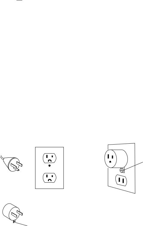
4.This product is for use on a nominal 120 V circuit, and has a grounding plug that looks like the plug illustrated in Fig. A. A temporary adaptor, which looks like the adaptor illustrated in Fig. C, may be used to connect this plug to a 2-pole receptacle as shown in Fig B. If a properly grounded outlet is not available, the temporary
adapter should be used only until a properly grounded outlet can be installed by a qualified electrician. The green colored rigid ear, lug, and the like, extending from the adaptor must be connected to a permanent
ground such as a properly grounded outlet box cover. Whenever the adaptor is used, it must be held in place by the metal screw.
Fig.B |
Fig.C |
|
|
Fig. A |
|
Metal screw
Fig.C
grounding means
II
TABLE OF CONTENTS
SETTING UP THE MACHINE |
|
Installing the Machine...................................................... |
2 |
Adjusting the feet........................................................... |
3 |
Names of Parts................................................................ |
5 |
Sub control panel........................................................... |
6 |
RCS unit (optional for some models)............................. |
6 |
Standard Accessories................................................. |
7-8 |
Assembling the Spool Stand............................................ |
9 |
Setting the Thread Cones or Spools of Thread.............. |
10 |
Setting the spool of thread........................................... |
10 |
Setting the thread cone................................................ |
10 |
Installing the Hoop Supporter......................................... |
11 |
Installing the RCS Unit (optional for some models)....... |
12 |
Connecting the Power Supply........................................ |
13 |
Direct PC-Link................................................................ |
14 |
Winding the Bobbin........................................................ |
15 |
Removing the bobbin case.......................................... |
16 |
Removing the bobbin................................................... |
16 |
Inserting the bobbin..................................................... |
17 |
Inserting the bobbin case............................................. |
17 |
Threading the Needle................................................ |
18-20 |
Threading the needle with the needle threader........... |
20 |
Stabilizers....................................................................... |
21 |
Template......................................................................... |
21 |
Setting the Fabric in the Embroidery Hoop.................... |
22 |
Setting the Embroidery Hoop......................................... |
23 |
Adjusting the Hoop Supporter for Optional Hoops......... |
23 |
BASIC OPERATION |
|
Basic Operation with the Sub Control Panel.................. |
24 |
Machine operating buttons........................................... |
24 |
Function buttons.......................................................... |
24 |
LCD screen.................................................................. |
25 |
Machine setting......................................................... |
26-27 |
Starting to Embroider................................................ |
28-29 |
Removing the Hoop....................................................... |
30 |
Adjusting the Thread Tension......................................... |
31 |
Replacing the needle..................................................... |
32 |
Basic Operation of the Optional RCS Unit..................... |
33 |
Machine operating buttons........................................... |
33 |
Panel keys.................................................................... |
34 |
On-screen Help Movie................................................... |
35 |
Disconnecting the RCS Unit........................................... |
36 |
ADVANCED OPERATION WITH THE OPTIONAL RCS UNIT
Selecting the Embroidery Patterns |
.................................37 |
Selecting the built-in designs.................................. |
38 -39 |
Function keys............................................................ |
40 -41 |
Monogramming.............................................................. |
42 |
Function keys............................................................... |
43 |
Entering the characters................................................ |
44 |
Deleting a character..................................................... |
45 |
Inserting a character.................................................... |
45 |
Saving the monogram.................................................. |
45 |
Placement of monogramming...................................... |
46 |
Multi-color monogramming........................................... |
47 |
Editing............................................................................ |
48 |
Editing Functions............................................................ |
49 |
Selecting the hoop....................................................... |
49 |
Moving the pattern....................................................... |
50 |
Resizing the pattern..................................................... |
50 |
Rotating the pattern..................................................... |
51 |
Deleting the pattern...................................................... |
51 |
Saving the file.............................................................. |
51 |
Alternate function key assignment............................... |
52 |
Duplicating the pattern................................................. |
52 |
Flipping the pattern...................................................... |
52 |
Monogramming in an arc............................................. |
53 |
Customizing the color setting....................................... |
54 |
Grouping the patterns.................................................... |
55 |
Color grouping............................................................. |
55 |
Zooming the editing window........................................... |
56 |
Combining the Patterns and Lettering....................... |
57-59 |
Adjusting the start position............................................. |
60 |
Adjusting the re-start position after thread breakage..... |
60 |
Starting to Embroider..................................................... |
61 |
Customizing the Settings with the |
|
Sub Control Panel..................................................... |
62-66 |
Customizing the Settings with the Optional |
|
RCS Unit................................................................... |
67-77 |
File Management........................................................... |
78 |
Saving the Pattern as a File......................................... |
78 |
Creating a new folder................................................... |
79 |
Changing the folder name............................................ |
79 |
Opening a file............................................................... |
80 |
File list option............................................................... |
81 |
Deleting the folder........................................................ |
82 |
Deleting the file............................................................ |
82 |
OPTIONAL ITEMS |
|
USB Flash Drive............................................................. |
83 |
CARE AND MAINTENANCE |
|
Cleaning the Hook.......................................................... |
84 |
Cleaning the Bobbin Case............................................. |
84 |
Cleaning the Tension Leaves and Disks........................ |
85 |
Cleaning the Auto Thread Cutter Mechanism................ |
86 |
Oiling......................................................................... |
87-88 |
Error Message................................................................ |
89 |
Troubleshooting........................................................ |
90-91 |
1
e
SETTING UP THE MACHINE
Installing the Machine
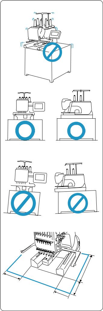
Place the machine on a flat and stable surface such as a sturdy table that could withstand the machine’s weight and vibration.
Place the machine on the flat and level surface. Make sure that all the feet firmly contact the surface.
Provide a sufficient space around the machine to allow the hoop to move freely.
q 20 cm (7–7/8˝) w 20 cm (7–7/8˝) e 30 cm (11–7/8˝)
q
w
q 
2
e
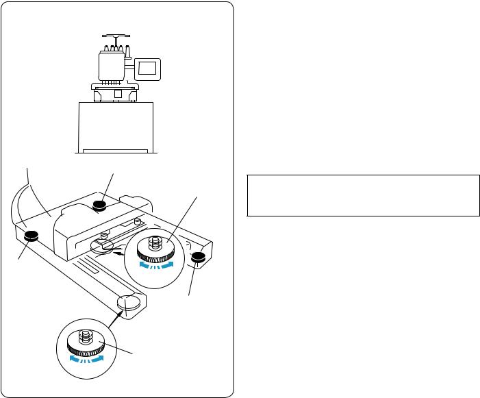
Adjusting the feet
Turn the adjusting screw counterclockwise (in the direction of A) as much as possible, before placing the machine on a surface.
q Adjusting screw
Place the machine on a flat and level surface.
Turn the adjustable foot so the four feet firmly contact the surface.
w Adjustable foot e Foot
Turn the adjusting screw clockwise (in the direction B) until it contacts the surface.
NOTE:
qMake sure that the machine sits on the surface without shaking.
e
B A
e
w
3

CAUTION:
Do not use the machine near appliances that radiate electromagnetic noise such as a microwave oven, or do not plug in the machine to the same branch circuit where such appliances are connected.
CAUTION:
Do not use or store the machine near a heat radiator or in a place with dust or high humidity.
CAUTION:
Do not expose the machine to direct sunlight or open air.
CAUTION:
Two or more persons are required when transporting the machine.
Hold the machine by the two legs and the hand grip on the bottom of the backside of the machine.
q Hand grip
* Remove the hoop supporter when transporting the machine to avoid damage by hitting the supporter.
q

4

q
!2
w
!1
e


!0
r
t
y
u i o
@0
@1
!9
 !8
!8

 !7
!7  !6
!6
!5
@2 |
!4 |
|
!3
@3
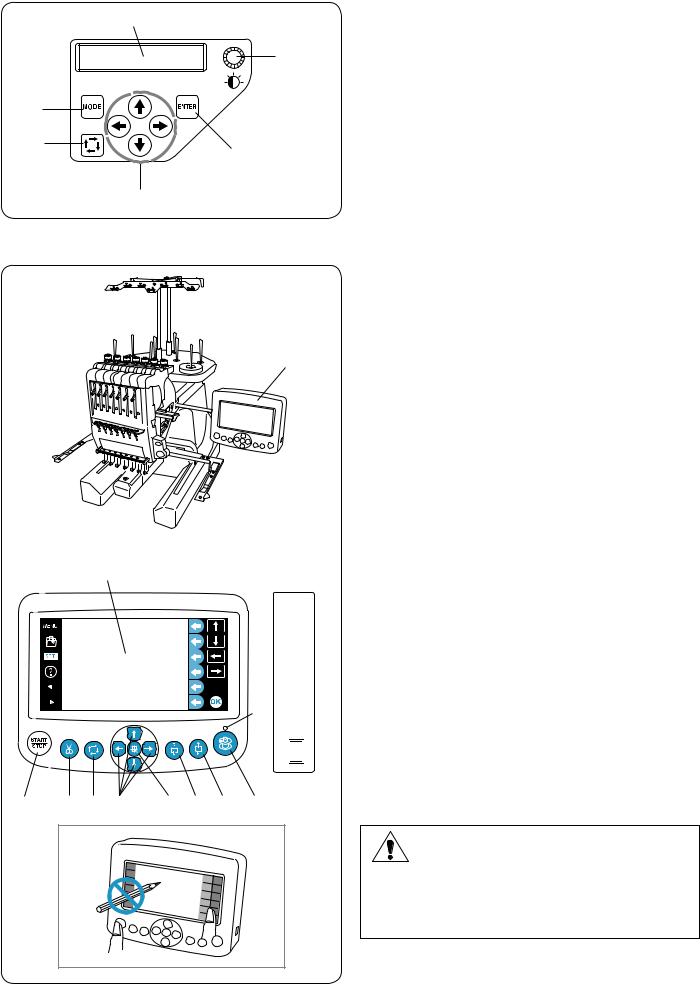
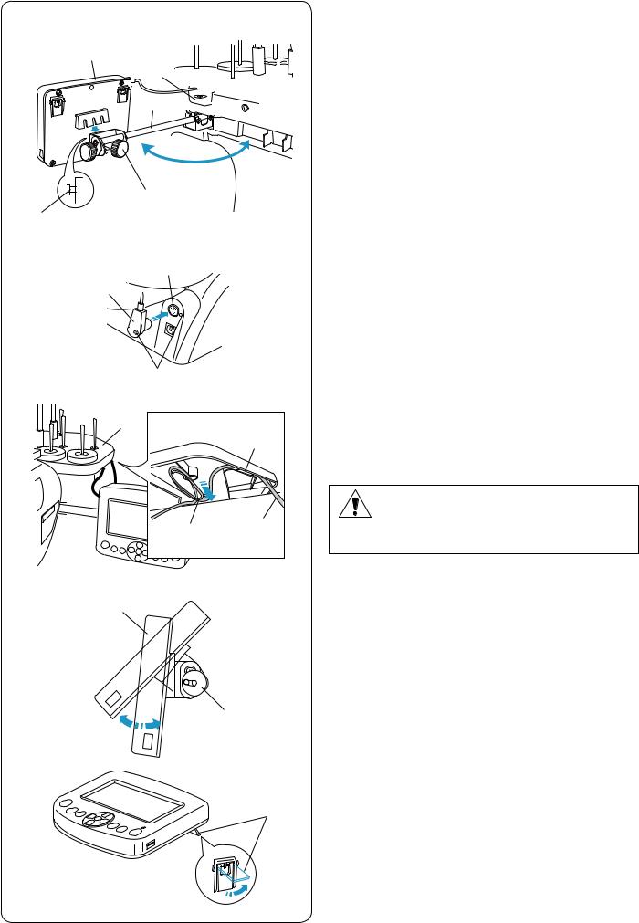
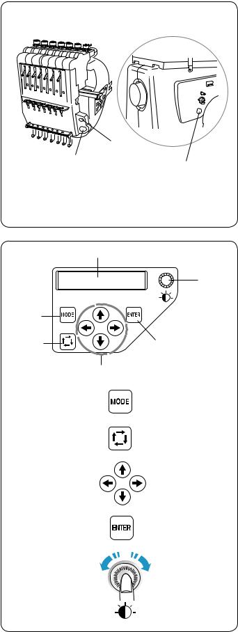
Names of Parts
q Thread guide bar w Pre-tension control e Tension control
r Check spring t Hoop supporter y Needle plate u Hook cover
i START/STOP button
o Auto thread cutter button !0Sub control panel !1Spool stand
!2Spool pins
*For assembling the thread guide bar and the spool stand, refer to page 9.
*For installing the hoop supporter, refer to page 11.
!3Machine socket !4Power switch !5Carriage
!6Bobbin winder button !7Bobbin winder stopper !8Bobbin winder spindle !9Bobbin thread cutter @0Bobbin winder thread guide @1Handwheel
@2RCS connector socket @3USB port
5
|
y |
Sub control panel |
|
q MODE button |
|
|
|
|
|
t |
w Trace button |
|
|
e Arrow buttons |
q |
|
r ENTER button |
|
t LCD brightness adjusting dial |
|
|
|
|
w |
|
y LCD display |
r |
|
|
|
|
|
|
e |
|
q
!2
!0


 !1
!1
w e r t y u i o
RCS unit (optional for some models)
q RCS unit
w START/STOP button
e Auto thread cutter button r Trace button
t Jog buttons
y Carriage return button u Stitch back button
i Stitch forward button o Bobbin winder button !0Bobbin winder indicator !1USB port
!2LCD touch panel
*The RCS unit is for 7-needle embroidery machine only and cannot be used for other models.
CAUTION:
Do not press the LCD touch panel with hard or sharp pointed objects like pencils, screwdrivers or the like.
Press the LCD touch panel and buttons gently. Rough or forceful pressing may damage the unit.
6
q |
w |
er
t |
y |
u
i |
|
o |
!0 |
!1 |
!2 |
|
!3 |
|
!4 |
Standard Accessories
q Needle (DB x K5Q1-NY, #11) (x 10) w Scissors
e Bobbin (x 5) r Lint brush t Seam ripper
y Handy needle threader u Spool cap (x 8)
i Spool net (x 15) o Screwdriver !0Screwdriver (small) !1Oiler
!2Tweezers !3Offset screwdriver !4Accessory box
7

q |
w |
e |
|
|
r |
|
|
|
t |
|
|
y |
|
|
|
|
|
u |
|
i |
|
|
|
o |
|
|
|
!0 |
|
!2 |
|
!1 |
|
|
|
|
|
!5 |
!9 |
!3 |
|
|
|
!4 |
!6 |
|
|
|
|
|
@0 |
|
!7 |
!8 |
|
|
|
|
8 |
Standard Accessories
q Instruction book w Instructional DVD
e Power supply cable r USB cable
t Screwdriver (large)
y Hoop M1 (MB Hoop 240 x 200 mm) (with template)
u Hoop M2 (MB Hoop 126 x 110 mm) (with template)
i Hoop M3 (MB Hoop 50 x 50 mm) (with template)
o Hoop supporter !0Felt ring (large) (x 8) !1Felt ring (small) (x 8) !2Spool rest (x 8) !3Thread guide bar !4Spool stand
!5Thread guide pole (x 2) !6Setscrew (x 3) !7Setscrew A (x 2) !8Setscrew B (x 2) !9Spool pin A (x 7) @0Spool pin B (x 1)
RCS unit (optional for some models)
|
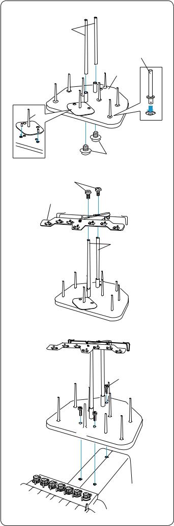
Assembling the Spool Stand |
z x |
z Insert the spool pins A into the spool stand. |
q |
Insert the thread guide poles and secure the poles |
|
with setscrews A from the bottom. |
|
q Thread guide poles |
rw Setscrews A e Spool stand
er Spool pin A
|
|
x Insert the spool pin B into the spool stand. |
|
|
t Spool pin B |
|
t |
|
|
|
w |
c |
u |
c Attach the thread guide bar to the thread guide poles |
|
|
with the setscrews B. |
|
y |
* Tighten the setscrews firmly with the screwdriver |
|
(large). |
|
|
|
|
|
|
y Thread guide bar |
|
|
u Setscrews B |
|
|
q |
v |
v Attach the assembled spool stand to the machine with |
|
the 3 setscrews. |
|
i Setscrews |
|
i |
i

9
|
t |
|
r |
w |
q |
|
|
e |
w |
|
|
|
e |
|
y |
|
e |
|
u |
|
w |
|
q |
|
o |
w |
i |
|
|
|
!0 |
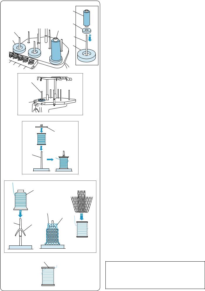
Setting the Thread Cones or Spools of Thread
Felt rings of two sizes are provided to accommodate various types of spools of thread and thread cones.
Use the large felt rings for large thread cones.
For small thread cones or spools of thread, insert the small felt rings into the large rings.
q Spool of thread w Spool pin
e Felt ring (large) r Felt ring (small)
t Small spool of thread
y Spool pin for bobbin winding
Setting the spool of thread
Place the spool of thread on the spool pin, with the thread coming out from the left backside.
Attach the spool cap and firmly press it against the spool. w Spool pin
u Spool cap
Setting the thread cone
Attach the spool rests on the spool pins. Place the thread cones on the spool pins.
Cover the thread cone with the spool net if the thread is shaky or kinky when sewing.
If the net is too long for a spool, fold the net and place it on the spool.
q Spool of thread w Spool pin
i Spool rest o Spool net
NOTE:
To prevent the thread from unraveling, leave the net on the thread cone or hook the thread end into the notch of the spool when it is not in use.
!0 Notch
10
|
|
Installing the Hoop Supporter |
z |
w |
CAUTION: |
|
Turn the power switch off before installing the hoop |
|
|
|
|
|
|
supporter. |
q |
|
z Loosen the two thumbscrews on the hoop supporter. |
|
|
|
|
|
q Hoop supporter |
|
|
w Thumbscrew |
x |
e |
x Hold the hoop supporter with both hands and place it |
|
|
under the carriage plate by inserting the necks of both |
|
|
thumbscrews into the slots in the carriage plate. |
|
|
e Slot in the carriage plate |
w
c |
c Tighten the thumbscrews with the screwdriver to |
w |
secure the hoop supporter. |
* When carrying the machine, remove the hoop supporter from the machine.
11
z x c
t
v
b
n m
r
q 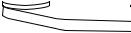 w
w 
e
y
u
i
oView from the bottom
!0
!2 !1
r
!3
!4
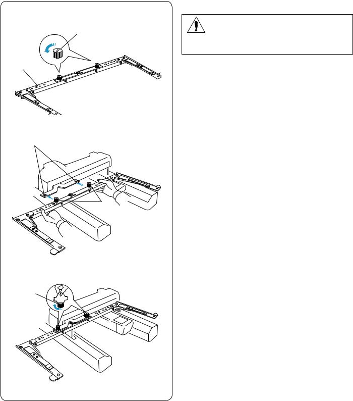
Installing the RCS Unit (optional for some models)
z Loosen the thumbscrew and open the mounting arm. q Thumbscrew
wMounting arm
x Loosen the screw knob A and set the RCS unit on the mounting arm by hooking the RCS unit on the pins.
Tighten the screw knob A to secure the RCS unit. e Screw knob A
r RCS unit t Pin
cAdjust the angle of the mounting arm as desired and tighten the thumbscrew.
q Thumbscrew
wMounting arm
v Insert the connector into the connector socket on the back of the machine with the marks aligned.
y Connector socket
uConnector i Mark
bFold and secure the cable under the spool stand as shown.
o Spool stand !0Cable slotted into ribs
!1Cable coming from connector !2Excess cable secured in the opening
CAUTION:
Make sure to secure the cable under the spool stand. A loose cable may interfere with the hoop.
nLoosen the screw knob B on the end of the mounting arm and tilt the RCS unit to adjust the angle of the LCD screen for easier viewing.
m Tighten the screw knob B to secure the RCS unit. r RCS unit
!3 Screw knob B
If you want to use the RCS unit without installing, extend the two legs on the backside of the RCS unit so that it rests on an angle for easier viewing.
!4Leg
12
Connecting the Power Supply
CAUTION:
Turn the power switch off before connecting the machine to the power supply.
z Turn the power switch off.
tq Power switch
cx Insert the machine plug into the machine socket.
q |
x |
r |
w Machine plug |
z |
|
|
e Machine socket |
e |
|
c Insert the power supply plug into the properly |
|
|
|
||
|
|
|
|
|
w |
|
grounded outlet. |
v |
|
|
r Power supply plug |
|
|
t Wall outlet (grounded) |
|
|
|
|
|
|
|
|
v Turn the power switch on. |
|
|
|
q Power switch |
 CAUTION:
While in operation, always keep your eyes on thevsewing area, and do not touch any moving parts such as the thread take-up lever, handwheel or needle.
Always turn off the power switch and unplug the machine from the power supply:
- when leaving the machine unattended. - when attaching or removing parts.
- when cleaning the machine.
Grounding Instructions:
This machine is equipped with a grounding cable and plug.
The plug must be plugged into an appropriate outlet that is properly installed and grounded.
If a properly grounded outlet is not available, contact a qualified electrician to install the properly grounded outlet.
Refer to page II for more instructions.
13
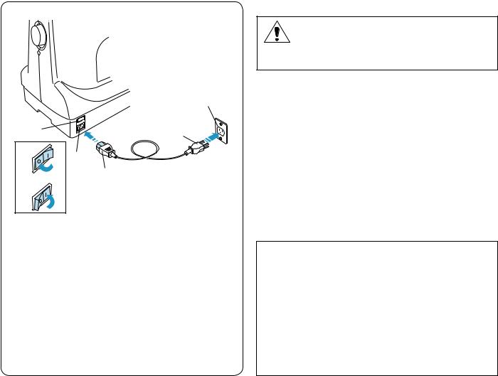
e
 PC
PC M
M
Direct PC-Link
The machine can be connected to PC with the USB cable included as standard accessory.
You need Digitizer V5 software (optional item) to operate the machine via direct PC-link.
q Type A USB connector w Type B USB connector e Transferring the data
Connecting the Machine and PC
Start up the machine and PC, and insert the type A USB
wconnector into the PC.
Insert the type B USB connector into the USB port on the machine.
For operating instructions, refer to the instruction manual of Digitizer V5.
|
CAUTION: |
q |
Do not turn the power switch off or disconnect the |
|
USB cable while the data transfer is in progress. |
|
Otherwise the data will be lost or the memory will be |
|
damaged. |
Embroidery Data Format
The following embroidery data formats can be used with this machine.
(1).jef (Janome embroidery format)
(2).jef + (editable Janome embroidery format)
(3).dst (Tajima embroidery format)
*Tajima format (.dst) does not have thread color information. Madeira (Rayon 40) thread color information will be assigned automatically.
14
z x
q
y
t u
c
v t |
b |
|
r |
n m
u
,
t
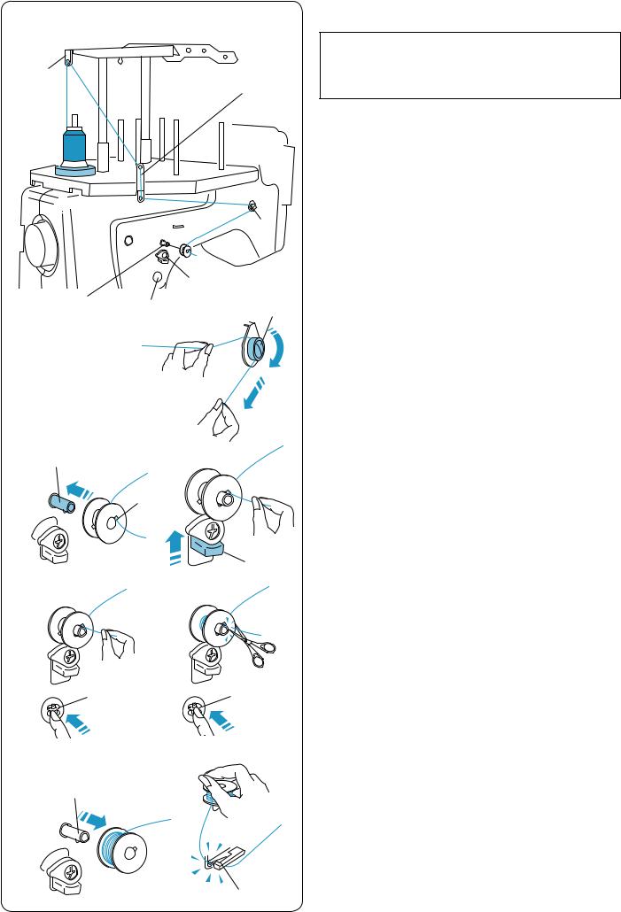
Winding the Bobbin
NOTE:
Cotton or spun polyester threads sizes 90 to 120 are recommended for bobbin thread.
wDo not use poor quality prewound bobbins.
zPlace the thread cone (spool of thread) on the rear most spool pin.
x Pass the thread through the thread guide A.
Pass the thread through the upper hole and lower hole in the thread guide B.
q Thread guide A
w Thread guide B
e
e
c Draw the thread to the front.
Hold the thread with both hands and pass the thread firmly around and under the tension disk.
e Tension disk
vPass the thread through the hole in the bobbin from the inside.
Put the bobbin on the bobbin winder spindle. r Hole in the bobbin
t Bobbin winder spindle
bPush the bobbin winder stopper up against the bobbin.
yy Bobbin winder stopper
nPress the bobbin winding button while holding the thread end.
u Bobbin winder button
|
m Press the bobbin winder button to stop the machine |
|
when the bobbin has wound a few layers. |
|
Cut the thread close to the bobbin and press the |
u |
bobbin winder button again. |
|
u Bobbin winder button |
|
, When the bobbin is fully wound, the machine will stop |
|
automatically. |
|
Remove the bobbin from the bobbin winder spindle. |
|
t Bobbin winder spindle |
|
Cut the thread with the bobbin thread cutter. |
|
i Bobbin thread cutter |
|
* Do not remove the thread from the bobbin thread |
i |
cutter after cutting the thread. |
|
15
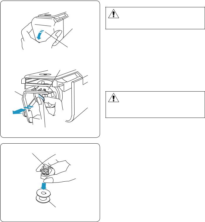
Removing the bobbin case
z |
CAUTION: |
|
Turn the power switch off before removing the bobbin case.
z Open the hook cover toward you. q Hook cover
q
x |
w |
x Hold and open the latch of the bobbin case. |
|
Take the bobbin case out from the machine.
w Bobbin case
e Latch
r
|
CAUTION: |
|
Do not force to pull the thread keeper when you |
|
remove the bobbin case. |
|
r Thread keeper |
|
e |
|
Removing the bobbin |
q |
Release the latch and take out the bobbin. |
|
q Latch |
|
w Bobbin |
w
16
z
w q
x c
r
e
 t
t
v
y
u
y 


 u i
u i
i
z
e


 w x r
w x r
q
Inserting the bobbin
zInsert the bobbin into the bobbin case leaving a
2˝ (5 cm) thread tail as illustrated.
q Bobbin
wBobbin case
x Draw the thread to slip it into the slit of the bobbin case.
e Slit
cPull the thread to slide it under the tension blade until the thread comes out from the notch.
r Tension blade
tNotch
v Draw the thread to the right behind the thread guide and slip the thread into the back slit.
y Back slit u Spring
iFront hole
*The bobbin should turn clockwise when the thread is pulled.
* Pull out about 2˝ (5 cm) of thread.
Inserting the bobbin case
CAUTION:
Turn the power switch off before inserting the bobbin case.
zHold the bobbin case with the latch and insert the bobbin case into the hook, aligning the bulge with the concave. Push the bobbin case as far as it will go and release the latch.
q Latch w Bulge e Concave
x Close the hook cover. r Hook cover
17
|
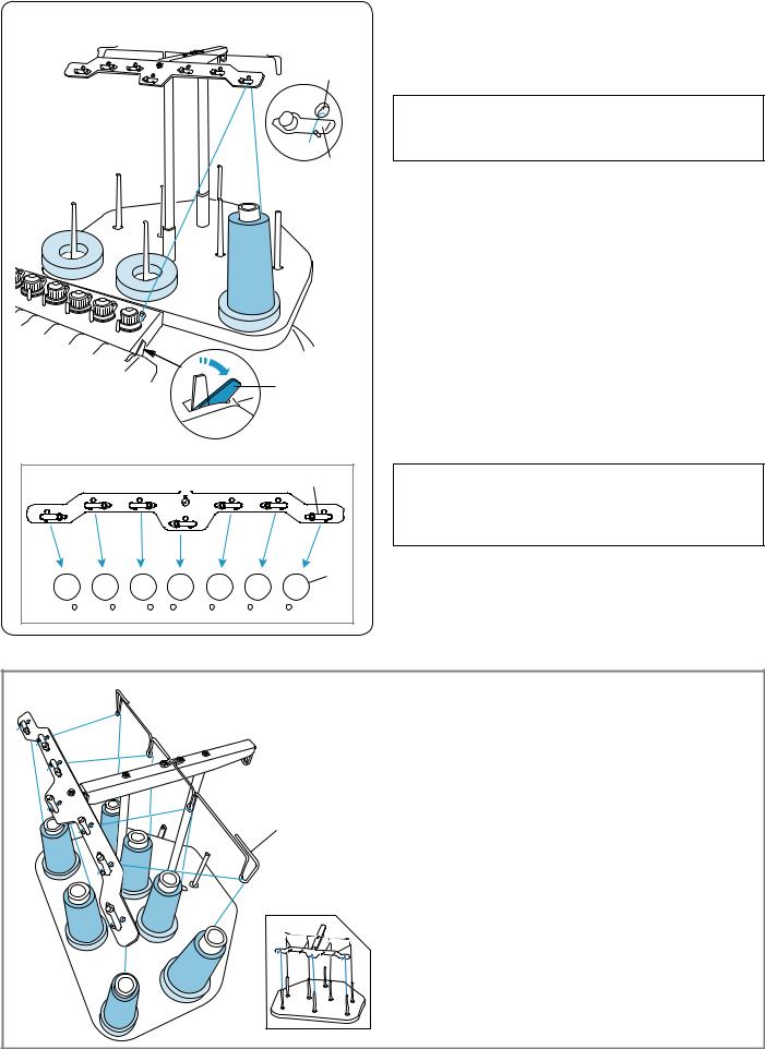
Threading the Needle |
|
z x |
The method of threading needle is all similar. |
|
Review the threading procedure of the first needle when |
||
|
||
w |
threading other needles. |
|
|
NOTE: |
|
|
Rayon threads are recommended for needles to |
|
|
achieve a better result. |
|
e |
|
|
|
Threading needle No.1 |
|
|
z Push back the tension release lever. |
|
|
q Tension release lever |
|
|
x Place a thread cone on the front right spool pin. |
|
|
Draw the thread up and pass it through the right hole |
|
|
in the thread guide bar from behind. |
|
|
Slip the thread under the tension leaf. |
|
|
w Hole in the thread guide bar |
|
|
e Tension leaf |
|
q |
|
e |
r |
NOTE:
Refer to the illustration for the thread path of each pre-tension.
r Pre-tension
|
|
|
Threading needles No. 2-7 |
|
|
|
For threading needles No. 4 and 7, draw the thread up |
|
|
|
and pass it through the hole in the thread guide bar |
|
|
|
from behind. |
|
|
|
For threading needles No. 2, 3, 5 and 6, pass the |
|
|
|
thread through the thread guide and pass is through |
|
6 |
t |
the hole in the thread guide bar from behind. |
|
t Thread guide |
||
|
|
||
7 |
|
|
|
|
|
Slip the thread under the tension leaf as illustrated. |
|
|
|
5 |
|
|
|
|
|
|
|
3 |
* The number on thread cone indicates the needle |
4 |
|
number. |
|
|
y |
||
|
|
|
y Threading path |
|
|
2 |
|
|
1 |
|
|
18
|
|
|
c Draw the thread to the right pre-tension control. |
c |
t |
|
Pass the thread through the guide hole from behind. |
|
|
While holding the thread with both hands, slip the |
|
|
|
|
|
|
r |
|
thread under the tension disk of the pre-tension |
|
|
|
control. |
|
|
|
Hook the thread around the guide pin from right to left |
|
u |
|
as shown in the threading path. |
|
|
Make sure to insert the thread under the tension disk |
|
|
r |
t |
|
|
|
|
by tugging the thread. |
|
|
u |
r Pre-tension control |
|
|
t Guide hole |
|
|
|
y |
|
|
|
|
y Threading path |
|
|
|
u Guide pin |
|
|
u |
|
v |
|
|
v Hold the thread with both hands and pull it down along |
|
|
|
the right channel. |
|
|
|
i Tension control |
i
b n m , .
!3
!4 !2 !0
o
⁄0 ⁄1 ⁄2 |
!6 |
!1 |
|
|
|
|
|
!5 |
|
|
!7 |
|
|
!8 |
bDraw the thread down and pass it through the right hole in the guide plate.
o Guide plate
!0Right hole in the guide plate
nPass the thread through the eye of the right check spring.
!1Eye of the check spring
mPull the thread up and pass it through the second hole from the right.
!2Second hole from the right
,Continue to pull the thread up to the right take-up lever. Pass the thread through the eye of the take-up lever.
!3Take-up lever
.Draw the thread down and pass it through the third hole from the right in the guide plate.
!4Third hole from the right
⁄0Continue to draw the thread down to the lower guide plate and pass the thread through the right hole.
!5Lower guide plate
!6Right hole in the lower guide plate
⁄1Hold the thread with both hand and slip the thread behind in the right needle bar thread guide.
!7Needle bar thread guide
⁄2Thread the needle with the handy needle threader (refer to the next page).
!8 Needle
19
⁄3
⁄4
z
x
c
v
@0
!9
q
q
w 
e
r
⁄3Pass the thread through the hole in the presser foot.
Draw the thread up and pinch the thread tail with the holder spring.
!9Hole in the presser foot @0Holder spring
⁄4Pull up the tension release lever to close the tension disks.
q Tension release lever
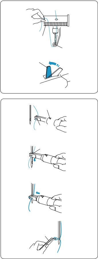
Threading the needle with the needle threader
zHold the needle threader with a triangle mark facing up. Insert the thread into the Y-notch of the threader from the right.
q Triangle mark w Y-notch
xSlide the threader down along the needle while pushing it gently until the threader pin goes into the needle eye.
Place the V-notch over the needle just above the needle eye.
e V-notch
cPush the threader until the threader pin comes out through the needle eye with a loop of thread.
vRemove the threader from the needle slowly, leaving the thread loop behind the needle eye.
Using the tweezers, pull the loop of the thread out to the back.
r Tweezers
20
q
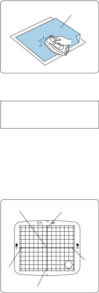
Adhesive (Iron-on) Stabilizer
Place the Wrong side of fabric and the glossy side of the stabilizer together. Fold up a corner of the stabilizer and fuse it with an iron.
NOTE:
•Fold up a corner of the stabilizer, to make it easier to peel off the excess stabilizer after stitching.
•Ironing temperatures vary depending on kind of adhesive type stabilizer.
qr
e
w
t
Stabilizers
To obtain the best quality embroidery, it is important to use stabilizers.
Types of stabilizer
•Tear-away stabilizer:
Use tear-away stabilizers for stable woven fabrics.
•Iron-on stabilizer:
Fuse it to the wrong side of the fabrics with an iron.
•Cut-away stabilizer:
Use cutaway stabilizers for knits and all kinds of unstable fabrics.
•Water soluble stabilizer:
Use this stabilizer for cutwork or lace embroidery, and also for the right side of looped fabrics such as toweling to avoid loops coming through the embroidery.
•Sticky stabilizer:
This stabilizer is a sticky paper used for securing a small fabric or work that cannot be secured in the hoop. It is also used for velvet and other napped fabric that would be permanently marked by the hoop.
Usage
The stabilizer should be attached to the wrong side of fabric.
More than one layer may be required.
Felt or stable fabrics do not need to be stabilized and you may embroider directly on them.
For firm fabrics, you may place a thin paper under the fabric.
The non-adhesive type should be used when embroidering fabric, which cannot be ironed or for sections, which are difficult to iron.
Cut the stabilizer larger than the embroidery hoop and set it on the hoop so that the entire piece is fastened within the hoop to prevent looseness of the fabric.
Template
Use the template to set the fabric in the embroidery hoop (refer to page 22).
qCenter point of design pattern
Alignment point of monogramming (center justify) for (vertical/horizontal orientation)
wAlignment point of monogramming (left justify) for horizontal orientation
eAlignment point of monogramming (right justify) for horizontal orientation
rAlignment point of monogramming (top justify) for vertical orientation
tAlignment point of monogramming (bottom justify) for vertical orientation
*For placement of monogramming, refer to page 46.
21
z |
q |
e
yw
x t
r
c |
u |
|


 i
i
o
v
o
b


 i
i
n


 i
i
m |
t |
|
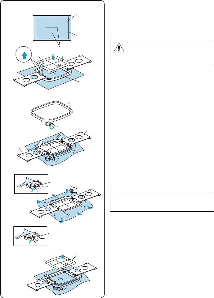
Setting the Fabric in the Embroidery Hoop
zAttach stabilizer to the wrong side of the fabric.
Mark the centerlines for pattern placement on the right side of the fabric.
q Fabric
w Centerlines e Stabilizer
CAUTION:
Thick and hard materials such as multi-layer canvas may cause needle to warp or break.
xPlace the inner hoop with the template on the fabric. Make sure that the arrow marks on the hoop and template are facing away from you.
Align the centerlines on the fabric and template. r Inner hoop
t Template y Arrow mark
c Loosen the hoop tightening screw on the outer hoop. u Outer hoop
iHoop tightening screw
v Hold the inner hoop and fabric together and push them into the outer hoop. Make sure to keep the centerlines aligned.
Do not push the setting plates. Push the 4 corners of the inner hoop.
o Setting plate
bTighten the hoop tightening screw slightly. Pull the edge of the fabric to stretch it drum-tight.
i Hoop tightening screw
NOTE:
Make sure the bottom of the inner hoop is level with the outer hoop.
nTighten the hoop tightening screw securely. i Hoop tightening screw
m Remove the template. t Template
22
|
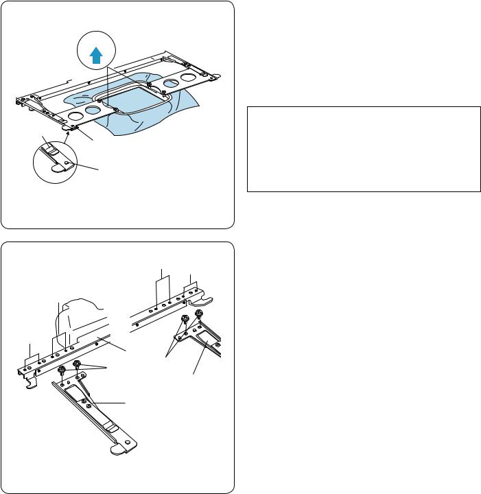
Setting the Embroidery Hoop |
|
|
Hold the setting plate with both hands and insert them |
|
r |
under the holder clips. |
|
Slide the hoop on the hoop supporter until the holes |
||
|
||
|
catch the positioning pins on the hoop supporter. |
|
|
q Holder clip |
|
|
w Positioning pin |
|
|
e Hole on the setting plate |
|
|
NOTE: |
|
q |
• Do not set the hoop front-side back or upside down. |
|
The arrow mark on the inner hoop should face away |
||
e |
||
|
from you. |
|
|
r Arrow mark |
|
w |
• Be careful not to pinch the fabric edge under the |
|
|
hoop supporter. |
|
|
Adjusting the Hoop Supporter for Optional |
|
B |
A |
Hoops |
|
The hoop supporter provides the position to adapt |
|||
|
|||
|
|
optional hoops available on the market, such as Tajima’s |
|
B |
|
hoop. |
|
|
|
Position A: M1 hoop (240mm x 200mm) |
|
|
|
M2 hoop (126mm x 110mm) |
|
A |
|
M3 hoop (50mm x 50mm) |
|
r |
|
Position B: Tajima hoops (optional) |
|
q |
|
|
|
q |
|
Remove setscrews on both left and right hoop supporter |
|
|
e |
||
|
|
arms and remove them. |
|
w |
|
q Setscrew |
|
|
|
Attach both hoop supporter arms to the hoop supporter |
|
|
|
bar in the position depending on the hoop you wish to |
|
|
|
use. |
|
|
|
Secure the supporter arms with the setscrews. |
|
|
|
w Left hoop supporter arm |
|
|
|
e Right hoop supporter arm |
|
|
|
r Hoop supporter bar |
23
BASIC OPERATION
Basic Operation with the Sub Control Panel
Machine operating buttons
|
|
|
|
q START/STOP button |
|
|
|
|
|
Press this button to start or stop the machine. |
|
|
|
|
|
* When you press this button once, the LCD screen will |
|
|
|
|
|
show the reminder [H:M1 ?] asking you to confirm the |
|
|
|
|
|
hoop type to be used. |
|
|
|
|
|
After checking the hoop type, press this button again to |
|
|
|
|
|
start sewing. |
|
|
w |
|
|
* The button glows red when the machine is stitching, |
|
|
q |
|
|
and green, when the machine has stopped. |
|
|
e |
|
w Auto thread cutter button |
||
|
|
|
|||
|
|
|
|
|
|
|
|
|
|
Press this button to trim the threads. |
|
|
|
|
|
e Bobbin winding button |
|
|
|
|
|
Press this button to wind the bobbin. |
|
|
y |
|
|
Use the sub control panel to operate the machine without |
|
|
|
|
the RCS unit. |
||
|
|
|
|
||
|
|
|
t |
Function buttons |
|
|
|
|
|
||
|
|
|
|
q MODE button |
|
q |
|
|
|
Press this button to select one of the following modes. |
|
|
|
|
|
1. |
Ready to Sew |
w |
r |
|
|
2. |
Stitch count setting |
|
|
|
|
3. |
Color section setting |
|
e |
|
|
4. |
Needle bar number setting |
|
|
|
|
5. |
Pattern selection |
|
|
|
|
6. |
My setting |
|
q |
|
|
w Trace button |
|
|
|
|
|
||
|
|
|
|
Press this button to trace the outline of the embroidery |
|
|
w |
|
|
pattern without stitching. |
|
|
|
|
e Arrow buttons |
||
|
|
|
|
||
|
e |
|
|
These buttons can be used as Jog buttons in the Ready |
|
|
|
|
to Sew mode. |
||
|
|
|
|
||
|
|
|
|
In other modes, these buttons are used for selecting the |
|
|
|
|
|
items. |
|
|
r |
|
|
r ENTER button |
|
|
|
|
Press this button to confirm your selection or register the |
||
|
|
|
|
||
|
|
|
|
settings. |
|
|
|
|
|
t LCD brightness adjusting dial |
|
|
t |
|
|
Turn this dial with your fingertip to adjust the brightness |
|
|
|
|
|
of the LCD screen. |
|
y LCD screen
24
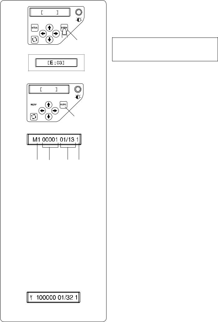
z |
W: 00 |
|
q
x |
W: 01 |
|
w
q
c
e r t y
(A)
LCD screen
zWhen turning the power on, the LCD screen will show [W:00].
Press the ENTER button and the hoop will move to the home position.
q ENTER button
NOTE:
If the LCD screen shows [E:03], press the ENTER button to initialize the needle bar position.
After initializing, the LCD screen will show [W:00].
xThe LCD screen will show [W:01].
Press the MODE button to start a new project or press the ENTER button if you wish to continue the last project before you turned the power off.
q ENTER button w MODE button
cThe LCD screen will show the Ready to Sew mode display.
In the Ready to Sew mode, the LCD screen shows the following information.
The LCD screen will show the Ready to Sew mode display.
In the Ready to Sew mode, the LCD screen shows the following information.
e Hoop type
•Standard hoops
M1: MB Hoop 240 x 200 mm M2: MB Hoop 126 x 110 mm M3: MB Hoop 50 x 50 mm
•Optional Tajima hoops
T1: Tajima hoop 34 mm dia. (933100239A00*) T2: Tajima hoop 54 mm dia. (933100439A00*) T3: Tajima hoop 84 mm dia. (933100639A00*) T4: Tajima hoop 112 mm dia. (933100839A00*) T5: Tajima hoop 142 mm dia. (933101039A00*)
T6: Tajima hoop 78 x 168 mm. (933200239A00*) (*Tajima part number)
•Optional special hoops
S1: Socks hoop 37 x 59 mm S2: Socks hoop 28 x 50 mm H1: Flat hat hoop 100 x 90 mm
•Optional monogram hoops
J1: No. 11 Monogram hoop 30 mm dia. J1: No. 12 Monogram hoop 30 mm dia. J2: No. 6 Monogram hoop 24 x 54 mm J3: No. 13 Monogram hoop 64 x 28 mm J4: No. 8 Monogram hoop 42 x 67 mm J5: No. 3 Monogram hoop 46 x 46 mm J6: No. 2, 9 Monogram hoop 66 x 66 mm J7: No. 1 Monogram hoop 110 x 95 mm J8: No. 7 Monogram hoop 120 x 121 mm
r Stitch count
*If the stitch count is 100 thousand or more, it will be indicated in 6 digits refer to the figure (A).
t Color section
13:Total number of colors
01: Order number of the current color y Needle bar number
25
 Loading...