


 Loading...
HOT WATER SANITIZING UNDERCOUNTER DISHMACHINES
TECHNICAL MANUAL
INSTALLATION MANUAL FOR EXPORT UNITS SERVICE MANUAL FOR DOMESTIC UNITS
FOR JACKSON MODELS:
JP-24
JP-24F
JP-24B
JP-24BF
March 6, 2006
P/N 7610-002-49-79 (Revision D)
An 


 Company
Jackson MSC, Inc.
P.O. BOX 1060
HWY. 25E
BARBOURVILLE, KY. 40906
FAX (606) 523-9196
PHONE (606) 523-9795
www.jacksonmsc.com

|
REVISION |
REVISION |
MADE |
APPLICABLE |
DETAILS |
|
|
DATE |
BY |
ECN |
|
||
|
|
|
|
|||
|
|
|
|
|
|
|
|
A |
07-15-2002 |
MAW |
6527 |
Release manual for service use. |
|
|
|
|
|
|
|
|
|
B |
06-04-2003 |
MAW |
6673, 6681 |
Updated per ecns. |
|
|
6637 |
|
||||
|
|
|
|
|
|
|
|
|
|
|
|
|
|
|
C |
02-11-2004 |
MAW |
6836 |
Updated per ecns. |
|
|
|
|
|
|
|
|
|
|
|
|
|
Change thermostat from 05930-121-71-29 to 05930-510-03-79. |
|
|
|
|
|
|
Change thermostat from 05930-121-71-36 to 05930-011-49-43. |
|
|
D |
03-06-2006 |
MAW |
7421, 7231 |
Change Diverter Valve Assembly number from 05700-002-23-21 |
|
|
6964, 7095 |
to 06410-012-23-21 & Diverter Valve Assembly 05700-002-23-22 |
|
|||
|
|
|
|
|
||
|
|
|
|
|
to 06401-022-23-21. Replace 04820-300-07-00 vacuum breaker |
|
|
|
|
|
|
with 04820-003-06-13. |
|
|
|
|
|
|
|
|
|
|
|
|
|
|
|
|
|
|
|
|
|
|
|
|
|
|
|
|
|
|
|
|
|
|
|
|
|
|
|
|
|
|
|
|
|
|
|
|
|
|
|
|
|
|
|
|
|
|
|
|
|
|
|
|
|
|
|
|
|
|
|
|
|
|
|
|
|
|
|
|
|
|
|
|
|
|
|
|
|
|
|
|
|
|
|
|
|
|
|
|
|
|
|
|
|
|
|
|
|
|
|
|
|
|
|
|
|
|
|
|
|
|
|
|
|
|
|
|
|
|
|
|
|
|
i

NOMENCLATURE FOR THE MODELS COVERED IN THIS MANUAL
JP-24B
JP-24 = Undercounter, high temperature, hot water sanitizing, no booster tank.
JP-24F = Undercounter, high temperature, hot water sanitizing, no booster tank, with top and side panels. JP-24B = Undercounter, high temperature, hot water sanitizing, with a booster tank.
JP-24BF = Undercounter, high temperature, hot water sanitizing, with a booster tank, with top and side panels.
Model:
Serial No.:
Installation Date:
Service Rep. Name:
Phone No.:
Jackson MSC Inc. provides technical support for all of the dishmachines detailed in this manual. We strongly recommend that you refer to this manual before making a call to our technical support staff. Please have this manual with you when you call so that our staff can refer you, if necessary, to the proper page. Technical support is available from 8:00 a.m. to 5:00 p.m. (EST), Monday through Friday. Technical support is not available on holidays. Contact technical support toll free at 1-888-800- 5672. Please remember that technical support is available for service personnel only.
ii

TABLE OF CONTENTS
SECTION |
DESCRIPTION |
PAGE |
I.SPECIFICATION INFORMATION
Specifications JP-24/JP-24F |
2 |
Specifications JP-24B/JP-24BF |
3 |
Dimensions |
4 |
II.INSTALLATION/OPERATION INSTRUCTIONS
|
Installation Instructions |
|
6 |
|
Electrical Installation Instructions |
7 |
|
|
Operation Instructions |
|
8 |
|
Detergent Control |
|
9 |
|
Cycle Counter Retrofit Kit Instructions |
10 |
|
III. |
PREVENTATIVE MAINTENANCE |
|
|
|
Preventative Maintenance |
|
12 |
IV. |
TROUBLESHOOTING |
|
14 |
V. |
SERVICE PROCEDURES |
|
|
|
Rinse Solenoid Valve Repair Parts Kit |
17 |
|
|
Vacuum Breaker Repair Parts Kit |
21 |
|
|
Replacing the Pump Motor /Booster Tank Heater |
23 |
|
|
Replacing the Drain Valve |
|
24 |
|
Rinse Regulating Thermostat Replacement |
25 |
|
VI. |
PARTS SECTION |
|
|
|
Gauge Panel Assembly |
|
30 |
|
Electrical Panel Assembly |
(JP-24/F 208-240 Volt, 50/60Hz) |
31 |
|
Electrical Panel Assembly |
(JP-24B/BF 208-240 Volt, 50/60Hz) |
32 |
|
Electrical Panel Assembly |
(JP-24B/BF 460 Volt, 60Hz) |
32 |
|
Gauge Panel Assembly (Used with the external mounted control panel assemblies) |
34 |
|
|
Electrical Panel Assembly |
(External & AMTRAK Option) |
34 |
|
Kick Plate Assembly |
|
37 |
|
Incoming Plumbing Assembly (JP-24/JP-24F) |
38 |
|
|
Incoming Plumbing Assemblies(JP-24B/JP-24BF) |
39 |
|
|
Rinse Stiffener/Rinse Hub Weldment |
40 |
|
|
Solenoid Valve Repair Kit/Vacuum Breaker Repair Kit/Water Pressure Regulator Kit (WPRK Option) |
41 |
|
|
Drain Valve Assembly |
|
42 |
|
Drain Plumbing Assembly |
|
43 |
|
Wash Motor to Wash Tub Assembly |
44 |
|
|
Rinse Tank & Components/Wash Heater Kit |
45 |
|
|
Door Assembly |
|
46 |
|
Miscellaneous Door Sub-Assemblies |
47 |
|
|
Rinse Arm & Wash Arm Assemblies |
48 |
|
|
Frame, Shroud, & Panel Components/Miscellaneous Parts |
49 |
|
|
Cycle Counter Retrofit Kit |
|
50 |
VII. |
SCHEMATICS |
|
|
|
JP-24/JP-24F 208/230 V, 50/60 HZ, single phase |
52 |
|
|
JP-24B/JP-24BF 208/230 V, 50/60 HZ, single phase |
53 |
|
|
JP-24B/JP-24BF 460 V, 60 HZ, three phase |
54 |
|
JP-24 Technical Manual 7610-002-49-79 Rev. D
Issued: 03-06-2006 Revised: N/A
iii

SECTION 1:
SPECIFICATION INFORMATION
1

SECTION 1: SPECIFICATION INFORMATION
SPECIFICATIONS of the JP-24/JP-24F
PERFORMANCE/CAPABILITIES |
|
ELECTRICAL REQUIREMENTS |
|
|
||||
OPERATING CAPACITY (RACKS/HOUR) |
|
WASH MOTOR HP |
|
|
3/4 |
|||
RACKS PER HOUR |
30 |
NOTE: Typical Electrical Circuit is based upon (1) 125% of the |
||||||
DISHES PER HOUR |
600 |
|||||||
full amperage load of the machine and (2) typical fixed-trip cir- |
||||||||
|
|
|||||||
GLASSES PER HOUR |
600 |
cuit breaker sizes as listed in the NEC 2002 Edition. Local |
||||||
|
|
codes may require more stringent protection than what is dis- |
||||||
|
|
played here. Always verify with your electrical service con- |
||||||
OPERATING CYCLE (SECONDS) |
|
tractor that your circuit protection is adequate and meets all |
||||||
|
applicable national and local codes. These numbers are pro- |
|||||||
WASH TIME |
82 |
|||||||
vided in this manual simply for reference and may change |
||||||||
DRAIN TIME |
28 |
without notice at any given time. |
|
|
||||
|
|
|
|
|
|
|||
RINSE TIME |
10 |
|
|
|
|
|
|
|
TOTAL CYCLE TIME (MINUTES) |
2 |
JP-24/JP-24F: |
|
|
|
|||
|
|
|
|
|
|
|||
|
|
|
|
|
RINSE |
|
TYPICAL |
|
5 MINUTE TIMER OPERATING CYCLE (SECONDS) |
|
|
|
HEATER |
TOTAL |
ELECTRICAL |
||
VOLTS |
PH |
HZ |
RATINGS |
AMPS |
CIRCUIT |
|||
WASH TIME |
262 |
208 |
1 |
50 |
900KW |
12 |
15 AMP |
|
DRAIN TIME |
28 |
230 |
1 |
50 |
1100KW |
12 |
15 AMP |
|
|
|
|
|
|
|
|||
RINSE TIME |
10 |
208 |
1 |
60 |
900KW |
10 |
15 AMP |
|
TOTAL CYCLE TIME (MINUTES) |
5 |
230 |
1 |
60 |
1100KW |
10 |
15 AMP |
|
|
|
|
|
|
|
|||
TANK CAPACITY (LITERS) (GALLONS) |
|
NOTE: Always refer to the machine data plate for specific |
||||||
|
electrical and water requirements. The material provided on |
|||||||
|
|
|||||||
WASH TANK |
(21.5) 5.65 |
this page is for reference only and may be subject to change |
||||||
|
|
without notice. |
|
|
|
|||
TEMPERATURES |
|
|
|
|
|
|
|
|
WASH --- (MINIMUM) |
(65.6°C) 150°F |
|
|
|
|
|
|
|
RINSE --- (MINIMUM) |
(82.2°C) 180°F |
|
|
|
|
|
|
|
WATER REQUIREMENTS |
|
|
|
|
|
|
|
|
INLET TEMPERATURE |
(82.2°C) 180°F |
|
|
|
|
|
|
|
GALLONS PER HOUR |
(198.7L) 52.3 |
|
|
|
|
|
|
|
WATER LINE SIZE I.P.S. (Minimum) |
(1.27 cm) 1/2” |
|
|
|
|
|
|
|
DRAIN LINE SIZE I.P.S. (Minimum) |
(3.81 cm) 1 1/2” |
|
|
|
|
|
|
|
FLOW PRESSURE P.S.I. |
20A5 |
|
|
|
|
|
|
|
FLOW, GALLONS PER MINUTE |
(27L) 7.1 |
|
|
|
|
|
|
|
JP-24 Technical Manual 7610-002-49-79 Rev. D
Issued: 03-06-2006 Revised: N/A
2

SECTION 1: SPECIFICATION INFORMATION
SPECIFICATIONS of the JP-24B/JP-24BF
PERFORMANCE/CAPABILITIES |
|
|
ELECTRICAL REQUIREMENTS |
|
|
|||
OPERATING CAPACITY (RACKS/HOUR) |
|
|
WASH MOTOR HP |
|
|
3/4 |
||
RACKS PER HOUR |
|
30 |
NOTE: Typical Electrical Circuit is based upon (1) 125% of the |
|||||
DISHES PER HOUR |
|
600 |
||||||
|
full amperage load of the machine and (2) typical fixed-trip cir- |
|||||||
|
|
|
||||||
GLASSES PER HOUR |
|
600 |
cuit breaker sizes as listed in the NEC 2002 Edition. Local |
|||||
|
|
|
codes may require more stringent protection than what is dis- |
|||||
|
|
|
played here. Always verify with your electrical service con- |
|||||
OPERATING CYCLE (SECONDS) |
|
|
tractor that your circuit protection is adequate and meets all |
|||||
|
|
applicable national and local codes. These numbers are pro- |
||||||
WASH TIME |
|
82 |
||||||
|
vided in this manual simply for reference and may change |
|||||||
DRAIN TIME |
|
28 |
without notice at any given time. |
|
|
|||
|
|
|
|
|
|
|
||
RINSE TIME |
|
10 |
|
|
|
|
|
|
TOTAL CYCLE TIME (MINUTES) |
|
2 |
|
|
|
RINSE |
|
TYPICAL |
|
|
|
|
|
|
|
||
|
|
|
|
|
|
HEATER |
TOTAL |
ELECTRICAL |
5 MINUTE TIMER OPERATING CYCLE (SECONDS) |
|
VOLTS |
PH |
HZ |
RATINGS |
AMPS |
CIRCUIT |
|
|
208 |
1 |
50 |
6.7KW |
40 |
50 AMP |
||
WASH TIME |
|
262 |
230 |
1 |
50 |
8.2KW |
43 |
60 AMP |
|
208 |
1 |
50 |
8.2KW |
47 |
60 AMP |
||
|
|
|
||||||
DRAIN TIME |
|
28 |
230 |
1 |
50 |
10KW |
51 |
70 AMP |
RINSE TIME |
|
10 |
220 |
1 |
50 |
9.15KW |
48 |
60 AMP |
|
|
|
|
|
|
|
||
TOTAL CYCLE TIME (MINUTES) |
|
5 |
208 |
1 |
60 |
6.7KW |
39 |
50 AMP |
|
|
|
230 |
1 |
60 |
8.2KW |
46 |
60 AMP |
|
|
|
208 |
1 |
60 |
8.2KW |
42 |
60 AMP |
TANK CAPACITY (LITERS) (GALLONS) |
|
|
230 |
1 |
60 |
10KW |
50 |
70 AMP |
WASH TANK |
(21.5) |
5.65 |
460 |
1 |
60 |
480/8.2KW |
11 |
15 AMP |
460 |
1 |
60 |
480/9.6KW |
14 |
20 AMP |
|||
RINSE TANK |
(11.4) |
3 |
|
|
|
|
|
|
|
|
|
NOTE: Always refer to the machine data plate for specific |
|||||
TEMPERATURES |
|
|
electrical and water requirements. The material provided on |
|||||
|
|
this page is for reference only and may be subject to change |
||||||
|
|
|
||||||
WASH --- (MINIMUM) |
(65.6°C) 150°F |
without notice. |
|
|
|
|||
RINSE --- (MINIMUM) |
(82.2°C) 180°F |
|
|
|
|
|
|
|
WATER REQUIREMENTS |
|
|
|
|
|
|
|
|
INLET TEMPERATURE (40° Booster Heater) (82.2°C) 140°F |
|
|
|
|
|
|
||
INLET TEMPERATURE (70° Booster Heater) (43.3°C) 110°F |
|
|
|
|
|
|
||
GALLONS PER HOUR |
(198.7L) 52.3 |
|
|
|
|
|
|
|
WATER LINE SIZE I.P.S. (Minimum) |
(1.27 cm) 1/2” |
|
|
|
|
|
|
|
DRAIN LINE SIZE I.P.S. (Minimum) |
(3.81 cm) |
1 1/2” |
|
|
|
|
|
|
FLOW PRESSURE P.S.I. |
|
20A5 |
|
|
|
|
|
|
FLOW, GALLONS PER MINUTE |
(27L) 7.1 |
|
|
|
|
|
|
|
JP-24 Technical Manual 7610-002-49-79 Rev. D
Issued: 03-06-2006 Revised: N/A
3

|
SECTION 1: SPECIFICATION INFORMATION |
|
||
|
|
JP-24 DIMENSIONS |
|
|
LEGEND |
|
|
2 1/2” (6.4 cm) Min. Wall Clearance |
|
|
|
|
|
|
A - Water Inlet 1/2” ID Female Pipe Thread, 2 1/2” |
|
|
||
AFF |
|
|
|
|
B - Detergent Feeder Connection |
|
|
|
|
C - Electrical Connection |
|
E |
|
|
D - Drain Connection Flexible Hose 6’ Free |
|
|
||
|
12” |
|
||
Length, |
|
|
19” |
|
1” ID x 1 3/8” OD |
|
|
(30.5 cm) |
(48.3 cm) |
E - Rinse Additive Connection |
|
|
22 5/8” |
|
|
|
|
|
|
|
|
|
|
(57.5 cm) |
|
|
|
C |
A |
|
|
DOOR OPEN |
|
16 3/4” |
|
|
|
(42.5 cm) |
|
|
|
|
|
|
|
|
6 1/2” |
|
|
D |
E |
(16.5 cm) |
24 1/4” |
|
|
|
(61.6 cm) |
|
|
|
|
|
|
|
|
|
4 1/2” |
|
|
|
|
(11.4 cm) |
|
|
C |
|
B |
|
33 1/4” |
|
|
|
(84.5 cm) |
|
|
|
|
|
|
|
A |
13 1/4” |
|
|
8 1/2” |
(33.7 cm) |
|
|
|
|
|
|
||
(21.6 cm) |
|
|
|
|
|
3 3/4” (9.5 cm) |
|
|
|
2 1/2” |
2 3/4” (7 cm) |
4 1/4” |
|
|
(10.8 cm) |
|
|
||
(6.47 cm) |
|
|
|
|
|
|
|
|
|
|
|
DIMENSIONS |
|
|
Height (minimum): |
33 |
1/4” (84.5 cm) |
Inside Clearance Height: |
14 |
1/2” |
(36.8 cm) |
Height (maximum): |
34 |
1/4” (87 cm) |
Inside Clearance Width: |
20 |
1/4” |
(51.4 cm) |
Width: |
24” (60.9 cm) |
Inside Clearance Depth: |
21 |
1/4” |
(54 cm) |
|
Depth: |
22 |
5/8” (57.5 cm) |
Door Open Depth: |
39 1/2” (100.3 cm) |
||
Wall Clearance (minimum): |
2 1/2” (6.4 cm) |
|
|
|
|
|
*All dimensions are for reference only and are subject to change without notice.
JP-24 Technical Manual 7610-002-49-79 Rev. D
Issued: 03-06-2006 Revised: N/A
4

SECTION 2:
INSTALLATION/OPERATION
INSTRUCTIONS
5
SECTION 2: INSTALLATION/OPERATION INSTRUCTIONS
INSTALLATION INSTRUCTIONS
VISUAL INSPECTION: Before installing the unit, check the container and machine for damage. A damaged container is an indicator that there may be some damage to the machine. If there is damage to both the container and machine, do not throw away the container. The dishmachine has been inspected and packed at the factory and is expected to arrive to you in new, undamaged condition. However, rough handling by carriers or others may result in there being damage to the unit while in transit. If such a situation occurs, do not return the unit to Jackson; instead, contact the carrier and ask them to send a representative to the site to inspect the damage to the unit and to complete an inspection report. You must contact the carrier within 48 hours of receiving the machine. Also, contact the dealer through which you purchased the unit.
UNPACKING THE DISHMACHINE: Once the machine has been removed from the container, ensure that there are no missing parts from the machine. This may not be obvious at first. If it is discovered that an item is missing, contact Jackson immediately to have the missing item shipped to you.
LEVEL THE DISHMACHINE: The dishmachine is designed to operate while being level. This is important to prevent any damage to the machine during operation and to ensure the best results when washing ware. The unit comes with adjustable bullet feet, which can be turned using a pair of channel locks or by hand if the unit can be raised safely. Ensure that the unit is level from side to side and from front to back before making any connections.
Adjustable Bullet Foot
PLUMBING THE DISHMACHINE: All plumbing connections must comply with all applicable local, state, and national plumbing codes. The plumber is responsible for ensuring that the incoming water line is thoroughly flushed prior to connecting it to any component of the dishmachine. It is necessary to remove all foreign debris from the water line that may potentially get trapped in the valves or cause an obstruction. Any valves that are fouled as a result of foreign matter left in the water line, and any expenses resulting from this fouling, are not the responsibility of the manufacturer.
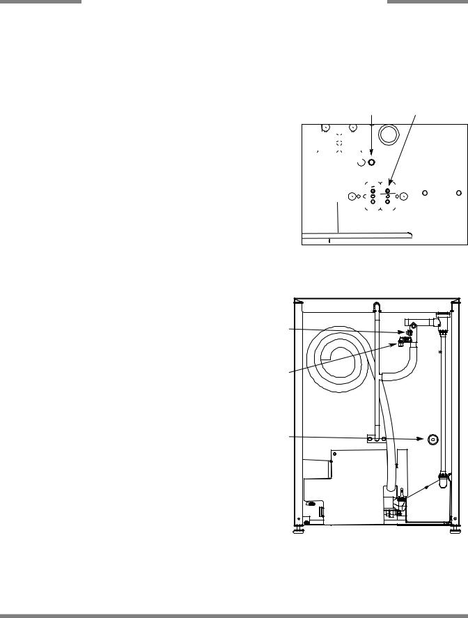
CONNECTING THE DRAIN LINE: The JP-24 series machines are a pumped (pressure) drain capable of pumping waste water to a height of 24 inches from the floor to the kitchen’s drain system. The dishmachines are supplied with a 10 foot long hose that extends from the rear side of the machine. There must also be an air gap between the machine drain line and the floor sink or drain. If a grease trap is required by code, it should have a flow capacity of 12 gallons (45.6 Liters) per minute.
WATER SUPPLY CONNECTION: Ensure that you have read the section entitled “PLUMBING THE DISHMACHINE” above before proceeding. Install the water supply line (1/2” ID pipe size minimum) to the dishmachine line y-strainer using copper pipe. It is recommended that a water shut-off valve be installed in the water line between the main supply and the machine to allow access for service. The water supply line is to be capable of 20A5 PSI “flow” pressure at the recommended temperature indicated on the data plate.
Drain Hose
Back of Machine Showing Drain Hose
Do to areas where the water pressure fluctuates or is greater than the recommended pres- 

 sure, it is recommended installing a water pressure regulator. Do not confuse static pressure


 with flow pressure. Static pressure is the line pressure in a “no flow” condition (all valves and
  services are closed). Flow pressure is the pressure in the fill line when the fill valve is


 opened during the cycle.


It is also recommended that a shock absorber (not supplied) be installed in the incoming water line. This prevents line hammer (hydraulic shock), induced by the solenoid valve as it operates, from causing damage to the equipment.
PLUMBING CHECK: Slowly turn on the water supply to the machine after the incoming fill line and the drain line have been installed. Check for any leaks and repair as required. All leaks must be repaired prior to placing the machine in operation.
Incoming Plumbing Y-Strainer
JP-24 Technical Manual 7610-002-49-79 Rev. D
Issued: 03-06-2006 Revised: N/A
6
SECTION 2: INSTALLATION/OPERATION INSTRUCTIONS
ELECTRICAL INSTALLATION INSTRUCTIONS
ELECTRICAL POWER CONNECTION: Electrical and grounding connections must comply with the applicable portions of the National Electrical Code ANSI/NFPA 70 (latest edition) and/or other electrical codes.
Disconnect electrical power supply and place a tag at the disconnect switch to indicate that you are working on the circuit.
The dishmachine data plate is located on the front of the machine. Refer to the data plate for machine operating requirements,
machine voltage, total amperage load and serial number. |
Ground Lug |
Terminal Block |
|
To install the incoming power lines, remove the kick panel. This will require taking a phillips head screwdriver and removing the two screws at the bottom of the kick panel; open the door slightly while carefully lifting the kick panel up and out of the way. Install 3/4” conduit into the pre-punched holes in the back of the control box. Route power wires and connect to power block and grounding lug. Install the service wires (L1 and L2) to the appropriate terminals as they are marked on the terminal block. Install the grounding wire into the lug provided. It is recommended that “DE-OX” or another similar anti-oxidation agent be used on all power connections.
VOLTAGE CHECK: Ensure that the power switch is in the OFF position and apply power to the dishmachine. Check the incoming power at the terminal block and ensure it corresponds to the voltage listed on the data plate. If not, contact a qualified service agency to examine the problem. Do not run the dishmachine if the voltage is too high or too low. Shut off the service breaker and mark it as being for the dishmachine. Advise all proper personnel of any problems and of the location of the service breaker. Replace the control box cover and tighten down the screws.
CHEMICAL CONNECTIONS: All chemical hookup locations are located on the back of the dishmachine. Please refer to the drawing at the right for the correct connection point.
Brass Plug
Rinse Aid Fitting
Detergent Fitting
JP-24 Technical Manual 7610-002-49-79 Rev. D
Issued: 03-06-2006 Revised: N/A
7

SECTION 2: INSTALLATION/OPERATION INSTRUCTIONS
OPERATION INSTRUCTIONS
PREPARATION: Before proceeding with the start-up of the unit, verify the following:
1.The strainer is in place and is clean.
2.That the wash and rinse arms are screwed securely into place and that their endcaps are tight. The wash and rinse arms should rotate freely.
POWER UP: To energize the unit, turn on the power at the service breaker. The voltage should have been previously verified as being correct. If not, the voltage will have to be verified.
FILLING THE WASH TUB:For the initial fill, close the door and depress the ON/FILL-OFF/DRAIN rocker switch in the ON position. The machine will run a partial cycle and fill to the factory preset level. Open the door and verify that the water level is correct. Hereafter, the water level is controlled by the timer that has been preset at the factory. Verify that there are no other leaks on the unit before proceeding any further. The wash tub must be completely filled before operating the wash pump to prevent damage to the component. Once the wash tub is filled, the unit is ready for operation.
NOTE: This applies to units with integral booster heaters. Make sure the orange wires at the heater contactor are connected properly. They have been purposely disconnected at the factory to avoid damage to the heater element when there is no water in the booster heater.
The machine runs a complete cycle to drain and fill. If the machine is not allowed to drain, the water will build up inside the tub. After the initial fill, the rinse water for the current cycle will become the wash water for the next cycle.
WARE PREPARATION: Proper preparation of ware will help ensure good results and less re-washes. If not done properly, ware may not come out clean and the efficiency of the dishmachine will be reduced. It is important to remember that a dishmachine is not a garbage disposal and that simply throwing unscraped dishes into the machine simply defeats the purpose altogether of washing the ware. Scraps should be removed from ware prior to being loaded into a rack. Pre-rinsing and pre-soaking are good ideas, especially for silverware and casserole dishes. Place cups and glasses upside down in racks so that they do not hold water during the cycle. The dishmachine is meant not only to clean, but to sanitize as well, to destroy all of the bacteria that could be harmful to human beings. In order to do this, ware must be properly prepared prior to being placed in the machine.
DAILY MACHINE PREPARATION: Refer to the section entitled “PREPARATION” at the top of this page and follow the instructions there. Afterwards, check that all of the chemical levels are correct and/or that there is plenty of detergent available for the expected workload.
WARM-UP CYCLES: For a typical daily start-up, it is recommended to run the machine through 3 cycles to ensure that all of the cold water is out of the system and to verify that the unit is operating correctly. To cycle the machine, ensure that the power is on and that the tub has filled to the correct level. Open the door and the cycle light will illuminate.
When the light goes out, close the door, the unit will start, run through the cycle, and shut off automatically. Repeat this two more times. The unit should now be ready to proceed with the washing of ware.
WASHING A RACK OF WARE: To wash a rack, open the door completely and slide the rack into the unit. Close the door and the unit will start automatically. Once the cycle is completed, open the door and remove the rack of clean ware. Replace with a rack of soiled ware and close the door. The process will then repeat itself.
OPERATIONAL INSPECTION: Based upon usage, the pan strainer may become clogged with soil and debris as the workday progresses. Operators should regularly inspect the pan strainer to ensure it has not become clogged. If the strainer does, it will reduce the washing capability of the machine. Instruct operators to clean out the pan strainer at regular intervals or as required by work load.
SHUTDOWN AND CLEANING: At the end of the workday, close the door. Start a cycle, then place the ON/FILL - OFF/DRAIN SWITCH to the “ OFF/DRAIN” position. The unit will automatically drain and turn off. Once the wash tub is drained, remove he pan strainer. Remove soil and debris from the strainer and set to the side. Unscrew the wash and rinse arms from their manifolds. Remove the endcaps and flush the arms with water. Use a brush to clean out the inside of the arms. If the nozzles appear to be clogged, use a toothpick to remove the obstruction. Wipe the inside of the unit out, removing all soil and scraps. Reassemble the wash and rinse arms and replace them in the unit. The arms only need to be hand tight, do not use tools to tighten them down. Reinstall the strainer and close the door.
JP-24 Technical Manual 7610-002-49-79 Rev. D
Issued: 03-06-2006 Revised: N/A
8

SECTION 2: INSTALLATION/OPERATION INSTRUCTIONS
DETERGENT CONTROL
Detergent usage and water hardness are two factors that contribute greatly to how efficiently your dishmachine will operate. Using detergent in the proper amount can become, in time, a source of substantial savings. A qualified water treatment specialist can tell you what is needed for maximum efficiency from your detergent, but you should still know some basics so you’ll understand what they are talking about.
First, you must understand that hard water greatly effects the performance of the dishmachine. Water hardness is the amount of dissolved calcium and magnesium in the water supply. The more dissolved solids in the water, the greater the water hardness. Hard water works against detergent, thereby causing the amount of detergent required for washing to increase. As you use more detergent, your costs for operating the dishmachine will increase and the results will decrease. The solids in hard water also may build-up as a scale on wash and rinse heaters, decreasing their ability to heat water. Water temperature is important in removing soil and sanitizing dishes. If the water cannot get hot enough, your results may not be satisfactory. This is why Jackson recommends that if you have installed the machine in an area with hard water, that you also install some type of water treatment equipment to help remove the dissolved solids from the water before it gets to the dishmachine.
Second, hard water may have you adding drying agents to your operating cycle to prevent spotting, when the real problem is deposited solids on your ware. As the water evaporates off of the ware, the solids will be left behind to form the spotting and no amount of drying agent will prevent this. Again, using treated water will undoubtedly reduce the occurrences of this problem.
Third, treated water may not be suitable for use in other areas of your operation. For instance, coffee made with soft water may have an acid or bitter flavor. It may only be feasible to install a small treatment unit for the water going into the dishmachine itself. Discuss this option with your qualified water treatment specialist.
Even after the water hardness problems have been solved, there still must be proper training of dishmachine operators in how much detergent is to be used per cycle. Talk with your water treatment specialist and detergent vendor and come up with a complete training program for operators. Using too much detergent has as detrimental effects as using too little. The proper amount of detergent must be used for job. It is important to remember that certain menu items may require extra detergent by their nature and personnel need to be made aware of this. Experience in using the dishmachine under a variety of conditions, along with good training in the operation of the machine, can go a long way in ensuring your dishmachine operates as efficiently as possible.
Certain dishmachine models require that chemicals be provided for proper operation and sanitization. Some models even require the installation of third-party chemical feeders to introduce those chemicals to the machine. Jackson does not recommend or endorse any brand name of chemicals or chemical dispensing equipment. Contact your local chemical distributor for questions concerning these subjects.
Some dishmachines come equipped with integral solid detergent dispensers. These dispensers are designed to accommodate detergents in a certain sized container. If you have such a unit, remember to explain this to your chemical distributor upon first contacting them.
As explained before, water temperature is an important factor in ensuring that your dishmachine functions properly. The data plate located on each unit details what the minimum temperatures must be for either the incoming water supply, the wash tank and the rinse tank, depending on what model of dishmachine you have installed. These temperatures may also be followed by temperatures that Jackson recommends to ensure the highest performance from you dishmachine. However, if the minimum requirements are not met, the chances are your dishes will not be clean or sanitized. Remember, a dish can look clean, but it may not be sanitized. Instruct your dishmachine operators to observe the required temperatures and to report when they fall below the minimum allowed. A loss of temperature can indicate a much larger problem such as a failed heater or it could also indicate that the hot water heater for your operation is not up to capacity and a larger one may need to be installed.
There are several factors to consider when installing your dishmachine to ensure that you get the best possible results from it and that it operates at peak efficiency for many years. Discuss your concerns with your local chemical distributor and water treatment specialist before there is a problem.
JP-24 Technical Manual 7610-002-49-79 Rev. D
Issued: 03-06-2006 Revised: N/A
9
SECTION 2: INSTALLATION/OPERATION INSTRUCTIONS
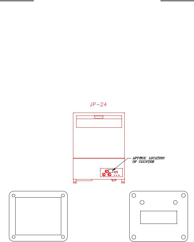
CYCLE COUNTER RETROFIT KIT INSTRUCTIONS
1.Locate the template on the front of the plastic control panel in the approximate location as shown in the diagram below.
2.Use a 3/32" diameter drill bit to drill the four mounting holes through the plastic control panel.
3.Mount the template to the front of the control panel using the screws and locknuts provided.
4.Using the template as a guide, cut the 1-3/8" x 1-1/8" cutout (the inside of the template) from the plastic control panel. Use a Dremel tool (or similar) or drill multiple holes along the edge of the template in order to cut away the cutout.
5.Remove the template from the control panel.
6.Assemble the counter (with mounting plate) to the control panel using the four screws and locknuts provided.
7.One lead wire from the counter is connected together with the blue wires from the fill solenoid valve and the rinse/fill light (using the existing wire nut that connects these two wires together).
8.The other lead wire from the counter is connected together with the red wires from the fill solenoid valve and the rinse/fill light (using the existing wire nut that connects these two wires together).
9.The counter should increment each time the fill solenoid valve is turned on.
Template, Cycle Counter Mount |
Cycle Counter Mount |
|
|
|
|
JP-24 Technical Manual 7610-002-49-79 Rev. D
Issued: 03-06-2006 Revised: N/A
10

SECTION 3:
PREVENTATIVE MAINTENANCE
11

SECTION 3: PREVENTATIVE MAINTENANCE
PREVENTATIVE MAINTENANCE
The dishmachines covered in this manual are designed to operate with a minimum of interaction with the operator. However, this does not mean that some items will not wear out in time. Jackson highly recommends that any maintenance and repairs not specifically discussed in this manual should be performed by QUALIFIED SERVICE PERSONNEL ONLY. Performing maintenance on your dishmachine may void your warranty if it is still in effect.
There are many things that operators can do to prevent catastrophic damage to the dishmachine. One of the major causes of component failure has to do with prescrapping procedures. A dishmachine is not a garbage disposal; any large pieces of material that are put into the machine shall remain in the machine until they are either broken up (after spreading out on your ware!) or physically removed. Strainers are installed to help catch debris, but they do no good if they are clogged. Have operators regularly inspect the pan strainers to ensure (1) that they are free of soil and debris and (2) they are laying flat in the tub.
When cleaning out strainers, do NOT beat them on waste cans. The strainers are made of metal and can be forgiving; but once severe damage is done, it is next to impossible for the strainer to work in the way it was designed to. Wipe out strainers with a rag and rinse under a faucet if necessary. For stubborn debris, a toothpick should be able to dislodge any obstructions from the perforations. Always ensure that strainers are placed back in the machine before operation and that they lay flat in the tub.
You may wish to also refer to the page entitled “Detergent Control” in order to learn more about how your water hardness will effect the performance of your machine. Hard water makes dishmachines work harder and decreases efficiency.
Again, it is important to remind operators that trying to perform corrective maintenance on the dishmachine could lead to larger problems or even cause harm to the operator. If a problem is discovered; secure the dishmachine using proper shut down procedures as listed in this manual and contact a QUALIFIED SERVICE AGENCY.
Some problems, however, may having nothing to do with the machine itself and no amount of preventative maintanence is going to help. A common problem has to do with temperatures being too low. Verify that the water temperatures coming to your dishmachine match the requirements listed on the machine data plate. There can be a variety of reasons why your water temperature could be too low and you should discuss it with a QUALIFIED SERVICE AGENCY to determine what can be done.
By following the operating and cleaning instructions in this manual, you should get the most efficient results from your machine. As a reminder, here are some steps to take to ensure that you are using the dishmachine the way it was designed to work:
1.Ensure that the water temperatures match those listed on the machine data plate.
2.Ensure that all strainers are in place before operating the machine.
3.Ensure that all wash and/or rinse arms are secure in the machine before operating.
4.Ensure that drains are closed/sealed before operating.
5.Remove as much soil from dishes by hand as possible before loading into racks.
6.Do not overfill racks.
7.Ensure that glasses are placed upside down in the rack.
8.Ensure that all chemicals being injected to machine have been verified as being at the correct concentrations.
9.Clean out the machine at the end of every workday as per the instructions in the manual.
10.Always contact a QUALIFIED SERVICE AGENCY whenever a serious problem arises.
11.Follow all safety procedures, whether listed in this manual or put forth by local, state or national codes/regulations.
JP-24 Technical Manual 7610-002-49-79 Rev. D
Issued: 03-06-2006 Revised: N/A
12

SECTION 4:
TROUBLESHOOTING
13
Loading...