


Conserver XL-E Series
DOOR TYPE DISHMACHINES
INSTALLATION & OPERATION MANUAL
FOR JACKSON MODEL(S):
CONSERVER XL-E
|
Jackson WWS, Inc. |
|
|
P.O. Box 1060, Hwy 25E |
|
October 14, 2014 |
Barbourville, KY USA |
|
1.888.800.5672 |
||
P/N 07610-003-92-84 D |
||
www.jacksonwws.com |
MANUFACTURERS WARRANTY
ONE YEAR LIMITED PARTS & LABOR WARRANTY
ALL NEW JACKSON DISHWASHERS ARE WARRANTED TO THE ORIGINAL PURCHASER TO BE FREE FROM DEFECTS IN MATERIAL OR WORKMANSHIP, UNDER NORMAL USE AND OPERATION FOR A PERIOD OF (1) ONE YEAR FROM DATE OF PURCHASE, BUT IN NO EVENT TO EXCEED (18) EIGHTEEN MONTHS FROM DATE OF SHIPMENT FROM THE FACTORY.
Jackson WWS agrees under this warranty to repair or replace, at its discretion, any original part which fails under normal use due to faulty material or workmanship during the warranty period, providing the equipment has been unaltered, and has been properly installed, maintained and operated in accordance with applicable factory instruction manual furnished with the machine and failure is reported to the authorized service agency within the warranty period. This includes the use of factory specified genuine replacement parts, purchased directly from a Jackson authorized parts distributor or service agency. Use of generic replacement parts may create a hazard and void warranty certification.
The labor to repair or replace such failed part will be paid by Jackson WWS, within the continental United States, Hawaii and Canada, during the warranty period provided a Jackson WWS authorized service agency, or those having prior authorization from the factory, performs the service. Any repair work by persons other than Jackson WWS authorized service agency is the sole responsibility of the customer. Labor coverage is limited to regular hourly rates; overtime premiums and emergency service charges will not be paid by Jackson WWS.
Accessory components not installed by the factory carry a (1) one year parts warranty only. Accessory components such as table limit switches, pressure regulators, pre-rinse units, etc. that are shipped with the unit and installed at the site are included. Labor to repair or replace these components is not covered by Jackson WWS.
This warranty is void if failure is a direct result from shipping, handling, fire, water, accident, misuse, acts of God, attempted repair by authorized persons, improper installation, if serial number has been removed or altered, or if unit is used for purpose other than originally intended.
TRAVEL LIMITATIONS
Jackson WWS limits warranty travel time to (2) two hours and mileage to (100) one hundred miles. Jackson WWS will not pay for travel time and mileage that exceeds this, or any fees such as those for air or boat travel without prior authorization.
WARRANTY REGISTRATION
To register your product go to www.jacksonwws.com or call 1-888-800-5672. Failure to register your product will void the warranty.
REPLACEMENT PARTS WARRANTY
Jackson replacement parts are warranted for a period of 90 days from date of installation or 180 days from the date of shipment from the factory, whichever occurs first.
PRODUCT CHANGES AND UPDATES
Jackson WWS reserves the right to make changes in design and specification of any equipment as engineering or necessity requires.
THIS IS THE ENTIRE AND ONLY WARRANTY OF JACKSON WWS. JACKSON’S LIABILITY ON ANY CLAIM OF ANY KIND, IN-
CLUDING NEGLIGENCE,WITH RESPECTTOTHE GOODS OR SERVICES COVERED HEREUNDER, SHALLIN NO CASE EXCEED THE PRICE OF THE GOODS OR SERVICES OR PART THEREOF WHICH GIVES RISE TO THE CLAIM.
THEREARE NO WARRANTIES, EXPRESSED OR IMPLIED, INCLUDING FOR FITNESS OR MERCHANTABILITY, THATARE NOT SET FORTH HEREIN, OR THAT EXTEND BEYOND THE DURATION HEREOF. UNDER NO CIRCUMSTANCES WILL JACKSON WWS BE LIABLE FOR ANY LOSS OR DAMAGE, DIRECT OR CONSEQUENTIAL, OR FOR THE DAMAGES IN THE NATURE OF PENALTIES, ARISING OUT OF THE USE OR INABILITY TO USE ANY OF ITS PRODUCTS.
ITEMS NOT COVERED
THIS WARRANTY DOES NOT COVER CLEANING OR DELIMING OF THE UNIT OR ANY COMPONENT SUCH AS, BUT NOT LIMITED TO, WASH ARMS, RINSE ARMS OR STRAINERS AT ANYTIME. NOR DOES IT COVER ADJUSTMENTS SUCH AS, BUT
NOT LIMITED TO TIMER CAMS, THERMOSTATS OR DOORS, BEYOND 30 DAYS FROM THE DATE OF INSTALLATION. IN
ADDITION, THE WARRANTY WILL ONLY COVER REPLACEMENT WEAR ITEMS SUCH AS CURTAINS, DRAIN BALLS, DOOR GUIDES OR GASKETS DURINGTHE FIRST30 DAYSAFTER INSTALLATION.ALSO, NOTCOVEREDARE CONDITIONS CAUSED BY THE USE OF INCORRECT (NON-COMMERICAL) GRADE DETERGENTS, INCORRECT WATER TEMPERATURE OR PRESSURE, OR HARD WATER CONDITIONS.
i

REVISION HISTORY
Revision |
Revision |
Made By |
Applicable ECNs |
Details |
|
Letter |
Date |
||||
|
|
|
|||
A |
01-06-14 |
MHH |
8241 |
Release to production. |
|
B |
08-18-14 |
KAP |
8305 |
Removed pg 17, updated part on page 20. |
|
C |
08-29-14 |
KAP |
N/A |
Updated part on pg. 27. |
|
|
|
|
|
Added 208 volt schematic on page 32. |
|
D |
10-14-2014 |
KAP |
N/A |
Updated available electrical characteristics on pg. 4. |
|
Updated Dimensions pg. 1 |
|||||
|
|
|
|
||
|
|
|
|
Updated part on pg. 29 |
|
|
|
|
|
|
|
|
|
|
|
|
|
|
|
|
|
|
|
|
|
|
|
|
|
|
|
|
|
|
|
|
|
|
|
|
|
|
|
|
|
|
|
|
|
|
|
|
|
|
|
|
|
|
|
|
|
|
|
|
ii
NOMENCLATURE FOR THE MODELS COVERED IN THIS MANUAL
CONSERVER XL-E
Chemical sanitizing, single-rack, door type machine
Model:
Serial No.:
Installation Date:
Service Rep. Name:
Phone Number:
Jackson WWS, INC provides technical support for all of the dishmachines detailed in this manual. We strongly recommend that you refer to this manual before making a call to our technical support staff. Please have this manual with you when you call so that our staff can refer
you, if necessary, to the proper page. Technical support is not available on holidays. Contact technical support toll free at 1-888-800-5672. Please remember that technical support is available for service personnel only.
iii

TABLE OF CONTENTS |
|
SPECIFICATIONS |
|
Machine Dimensions .................................................................................................................. |
1 |
Table Dimensions ....................................................................................................................... |
2 |
Operating Parameters ................................................................................................................ |
3 |
Electrical Requirements ............................................................................................................. |
4 |
INSTALLATION |
|
Instructions ................................................................................................................................. |
7 |
False Panel Instructions ........................................................................................................... |
10 |
Operating Instructions .............................................................................................................. |
11 |
Delime Instructions ................................................................................................................... |
13 |
MAINTENANCE |
|
Preventative Maintenance ........................................................................................................ |
14 |
Troubleshooting ........................................................................................................................ |
15 |
Solenoid Valve Instructions ..................................................................................................... |
17 |
PARTS |
|
Control Box Components .......................................................................................................... |
18 |
Chemical Feeder Pump Components ...................................................................................... |
20 |
Hood Assembly ........................................................................................................................ |
21 |
Door Assembly ......................................................................................................................... |
22 |
Wash Arm Assembly ................................................................................................................ |
24 |
Wash Manifold Assembly ......................................................................................................... |
25 |
Tub Assembly .......................................................................................................................... |
26 |
Wash Sump Assembly ............................................................................................................. |
27 |
Spillway Assembly ................................................................................................................... |
28 |
Pump & Motor Assembly .......................................................................................................... |
29 |
Frame Assembly ...................................................................................................................... |
30 |
Miscellaneous .......................................................................................................................... |
31 |
SCHEMATICS |
|
Electrical Schematics .............................................................................................................. |
32 |
iv

SPECIFICATIONS
MACHINE DIMENSIONS (Cons XL-E 115/60/1)
1 (24.63 mm)
13 1/4 (337.18 mm)
29 1/2 (750.28mm)
E1 |
30 3/8 (772.63 mm) |
|
6 (152.40 mm) |
6 3/4 (171.45 mm) |
|
|
DET |
|
SAN |
17 1/4 (438.15 mm) |
RA |
|
56 7/8 (1444.05 mm) |
29 1/2 (748.82 mm)
33 1/2 (852.45 mm)
ALL VERTICAL DIMENSIONS ARE
 +/- 1 2" FROM
 FLOOR
FLOOR

W
78 (1981.20 mm) WITH
 DOORS OPEN
65 (1649.52 mm)
|
|
|
D |
9 3/4 (247.65 mm) |
|
|
|
|
|
|
|
2 1/2 (62.57 mm) |
|
13 (330.20 mm) |
E1 |
MAIN ELECTRICAL CONNECTION (1.125” DIA HOLE) |
RA |
RINSE AND INLET |
|
|
(Located on back of control box) |
CP |
N/A |
|
W |
MAIN INLET WATER CONNECTION (½ NPT-F) |
|
||
S* |
N/A |
|
||
D |
DRAIN CONNECTION (2” NPT-F) |
|
||
C* |
N/A |
|
||
DET |
DETERGENT BULKHEAD ACCESS (.875” DIA HOLE) |
|
||
VI |
N/A |
|
||
SAN** |
SANITIZER INLET |
|
||
V2 |
N/A |
|
||
|
|
|
1
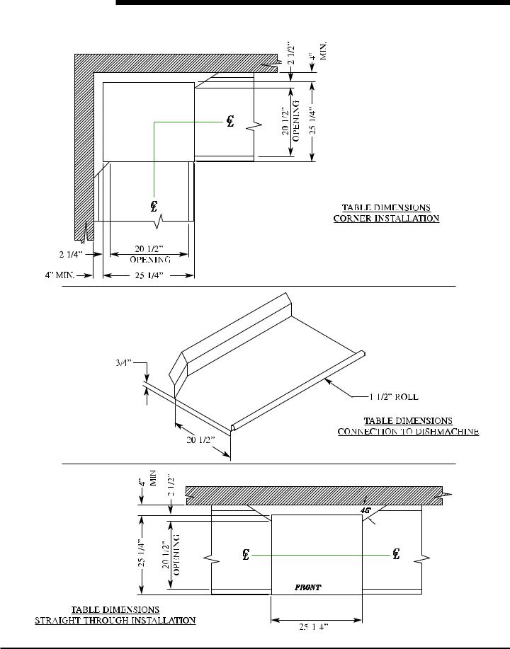
SPECIFICATIONS
TABLE DIMENSIONS
2

SPECIFICATIONS
OPERATING PARAMETERS
Model Designation: |
CONS XL-E |
Operating Capacity: |
|
Racks per Hour |
39 |
Dishes per Hour |
624 |
Glasses per Hour |
1404 |
Tank Capacity (Gallons): |
|
Wash Tank |
1.44 (90 GPH) |
Electrical Loads (as applicable): |
|
Wash Motor HP |
3/4 |
NOTE: Always refer to the machine data plate for specific electrical and water requirements.
The material provided on this page is for reference only and is subject to change without notice.
CHEMICAL SANITIZING
Water Temperatures (Fahrenheit/Celsius):
Minimum Wash Temperature |
120/49 |
Minimum Rinse Temperature |
120/49 |
Incoming Water Temperature |
120/49 |
Other Water Requirements: |
|
Water Flow Pressure (PSI) |
15 |
Flow Rate Minimum (GPM) |
1.03 |
Water Line Size (NPT) |
1/2” |
Drain Line Size (NPT) |
2” |
Minimum Chlorine Required (PPM) |
50 |
3

SPECIFICATIONS
ELECTRICAL REQUIREMENTS
CONS XL-E
|
|
|
Wash |
Drive |
Wash |
|
|
|
Volts |
Phase |
Freq |
Motor |
Motor |
Heater |
FLA |
MCA |
MOP |
|
|
|
Amps |
Amps |
Pumps |
|
|
|
|
|
|
|
|
|
|
|
|
115 |
1 |
60 |
11.4 |
N/A |
N/A |
11.4 |
14.3 |
25.7 |
Note 1: MCA (Minimum Circuit Ampacity) = 125% x Largest Motor + FLA of all other motors + all other loads.
Note 2: MOP (Maximum Overcurrent Protective Device) = 225% x Largest Motor + FLA of all other motors + all other loads.
Note 3: All electrical ratings provided in this manual are for reference only. Always refer to the machine data plate to get the exact electrical information for your machine. All electrical work performed on machines should be done in accordance with applicable local, state, territorial and national codes. Work should only be performed by qualified electricians and authorized service agents.Alist of authorized service agencies is located in the back of this manual.
Note that all electrical wiring used in the dishmachine must be rated, at a minimum, for 100°C (212°F). Furthermore, use copper conductors only.
Where applicable, heating element amperage draws have been adjusted for the assumed input voltage. Jackson assumes incoming voltages will be either 115, 208, 230 or 460 volts. Some of the heating elements used in our machines are actually rated for other voltages, such as 240 or 480 volts.Always verify the amperage draw of the machine in operation when sizing circuit protection.
The electrical configurations of the machines are as follows:
Available Electrical Characteristics:
•115 volt, 60 Hz, single phase
•115 volt, 50 Hz, single phase
•230 volt, 60 Hz, single phase
•220 volt, 60 Hz, single phase
4
INSTALLATION
INSTRUCTIONS
VISUAL INSPECTION: Before installing the unit, check the container and the machine for damage. A damaged container may be an indication there is possible damage to the product. If there is any type of damage to both the container and the unit, DO NOT THROW AWAY THE CONTAINER. The dishmachine has been previously inspected at the factory and is expected to arrive to you in new, undamaged condition. However, rough handling by carriers or others may result in damage to the unit while it is in transit. If such a situation occurs, DO NOT RETURN THE UNIT TO THE MANUFACTURER. Instead, contact the
carrier and ask them to send a representative to the site to inspect the damage. You should request that an inspection report be completed. You must contact the carrier within 48 hours of receiving the machine in order to report possible freight damage. You are also encouraged to contact the dealer through which you purchased the unit.
UNPACKING THE MACHINE: The machine should be unboxed and removed from the pallet prior to installing. Open the front door and remove all of the materials from the inside. Once unpacked, verify there are no missing parts. If you discover a part is missing, contact Jackson immediately.
LEVEL THE DISHMACHINE: The dishmachine is designed to operate while level. This is important to prevent any damage to the machine during operation and to ensure the best results possible. The unit comes equipped with adjustable bullet feet,
which can be turned using a pair of pliers. Verify the unit is level from front to back and side to side prior to making any electrical or plumbing connections.
PLUMBING THE MACHINE: All plumbing connections must be made to adhere to local, state, territorial and national codes.
The installing plumber is responsible for ensuring the incoming water lines are flushed of debris prior to connecting to the machine. Note that chips and materials from cutting processes can become lodged in the solenoid valves and prevent them from opening or closing. Any valves that are found to be fouled or defective because of foreign matter left in the water line, and any subsequent water damage, are not the responsibility of the manufacturer.
Water hardness should be a maximum of 6 grains per gallon. Hard water should be treated prior to being used by the machine.
Iron in the water line can cause staining.Afilter designed to remove iron from the water supply is highly recommended for supplies in excess of 0.1 ppm.
The water supply line shall be ½” NPT minimum and must be able to provide water at the minimum temperature indicated on the machine data plate.
The unit utilizes a flow pressure of 15 PSI for the incoming water line. Do not confuse static pressure with flow pressure. Static pressure is the pressure present when there is no flow and the valves are closed; flow pressure is present when the water is running into the machine. In areas where pressure fluctuates or is greater than the recommended pressure, it is suggested that a water pressure regulator valve be installed.
It is recommended that a shut-off valve be installed to allow isolating the dishmachine from the water system in the event that maintenance or other activities are required. Also, it is suggested that a shock absorber (not supplied with dishmachine) be installed on the incoming water line. This prevents water hammer (hydraulic shock)—induced by the solenoid valve as it operates—from causing damage to the equipment.
CONNECTING THE DRAIN LINE: The drain for the unit is a gravity discharge drain. All piping to the machine drain must be a minimum 2” NPTAND SHALL NOT BE REDUCED. There must also be an air gap between the machine drain line and the floor sink or drain. If a grease trap is required by code, it should have a flow capacity of 5 gallons.
5

INSTALLATION
INSTRUCTIONS
ELECTRICAL POWER CONNECTIONS: All electrical connections are to be made in accordance with applicable portions of local, state, territorial and national codes.
DISCONNECT ELECTRICAL POWER SUPPLIES AND TAG OUT IN ACCORDANCE WITH APPROPRIATE PROCEDURES AND CODES AT THE DISCONNECT SWITCH TO INDICATE YOU ARE WORKING ON THAT CIRCUIT.
This manual provides reference information regarding electrical requirements and loads, but that information may change without notice. Always refer to the machine data plate for voltage requirements, machine voltage, total amperage load and serial number. If you cannot read your data plate because it has been damaged, you should contact the manufacturer.
The main power terminal blocks (for the dishmachine and for the rinse booster heater, if applicable) are located at the top of the machine. You will have to remove the top cover to access these connections. Route incoming power lines within conduit that will connect via fittings to the pre-punched holes in the back of the Control Box. Install power and ground wires to lugs as indicated by the appropriate decals in the control box. Use copper conductors only. Use of an anti-oxidation agent is permissible on the power connections. Tighten all connections.
Verify the incoming voltage matches the voltage indicated on the decal next to the incoming power pre-punched hole.
DISHMACHINE VENTILATION: The dishmachine should be located into an adequate exhaust hood or ventilation system with provisions for venting. This is essential to permit efficient removal of the condensation exhaust. Ensure the exhaust system is acceptable in accordance with applicable codes and standards.
Note: Any damage that is caused by steam and/or moisture due to improper ventilation is NOT covered under the warranty.
The dishmachine has the following ventilation requirements: 200 CFM
The exhaust system must be sized to handle this volume for the dishmachine to operate in the manner it was designed.
THERMOSTATS: The thermostats on your unit have been set at the factory for the wash tank. They should only be adjusted by an authorized service agent.
TO PREPARE CHEMICAL PUMPS FOR OPERATION: The Conserver XL-E dishmachine is supplied with detergent, rinse additive and sanitizer-dispensing chemical feeder pumps. Locate the open ends of the chemical tubes with the tube stiffeners and place each one in the appropriate container.
A. Red Tubing = Detergent B. Blue Tubing = Rinse Aid C. White Tubing = Sanitizer
PRIMING CHEMICAL FEEDER PUMPS: Chemical feeder pumps need priming when the machine is first installed or if the chemical lines have been removed and air is allowed to enter.
6
 Loading...