

Page 1

Vacuum Pump VP5
EN Operating Instructions
Page 3
DE Bedienungsanleitung
Seite 13
FR Mode d’emploi
Page 23
IT Istruzioni d’uso
Pagina 33
ES Instrucciones de uso
Página 43
PT Instruções Operacionais
Página 53
Page 2

2
Page 3

Vacuum Pump VP5
Page
List of Parts 4
1. Introduction / Signs and Symbols 5
1.1 Preface
1.2 Introduction
1.3 Signs and symbols
2. Safety First 6
2.1 Indications
2.2 Health and safety instructions
3. Product Description 7
3.1 Components
3.2 Functional description
3.3 Hazardous areas and safety equipment
4. Installation 8
4.1 Unpacking and checking the contents
4.2 Selecting the location
4.3 Making the connections
5. Start-Up 9
6. Operation 9
7. Maintenance, Cleaning, and Diagnosis 10
7.1 Monitoring and maintenance
7.2 Cleaning
7.3 Notes on maintenance
english
8. What If... 11
8.1 Technical malfunctions
8.2 Repairs
9. Product Specifications 12
9.1 Delivery from
9.2 Technical data
9.3 Acceptable operating conditions
9.4 Acceptable transportation conditions
3
Page 4
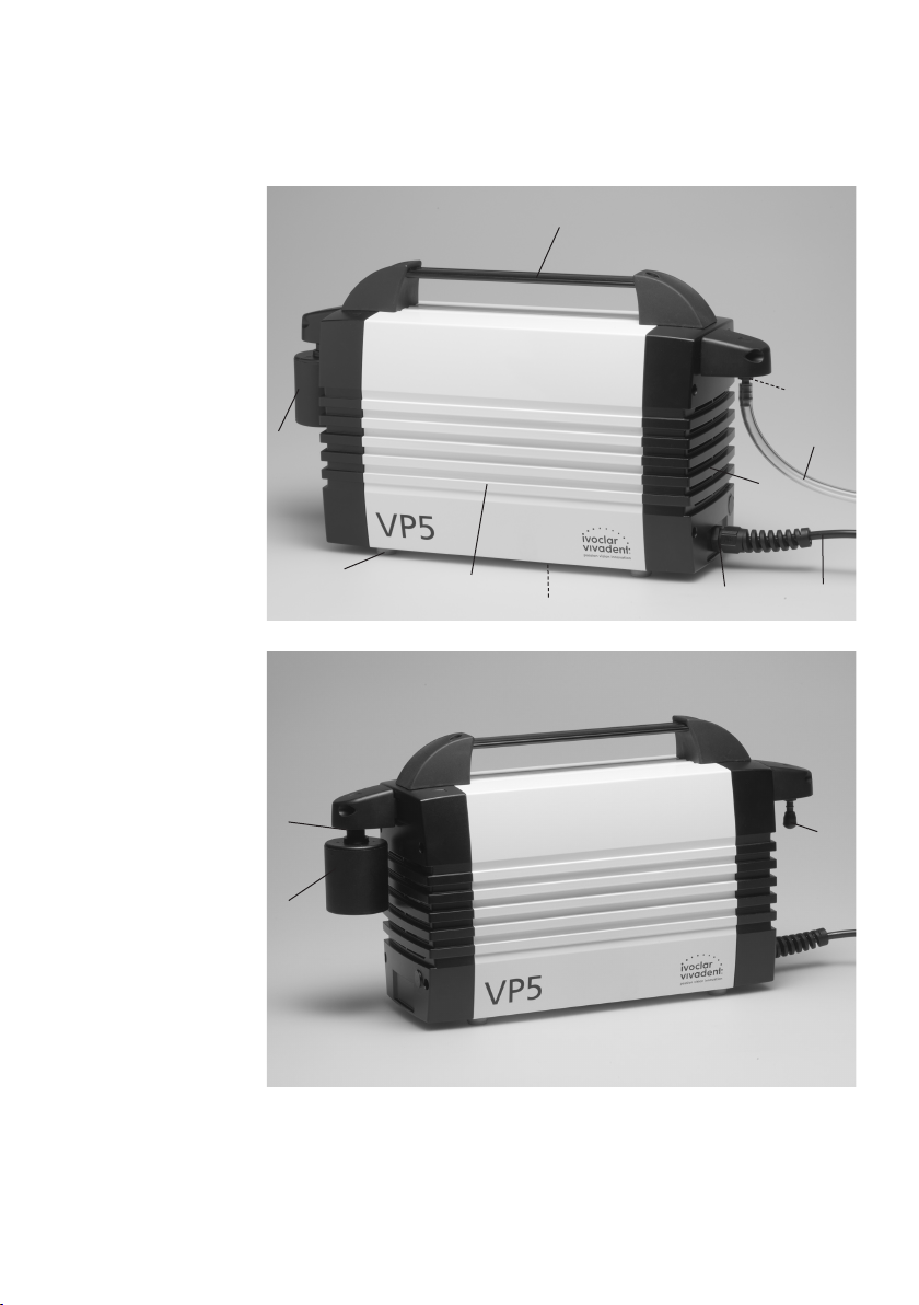
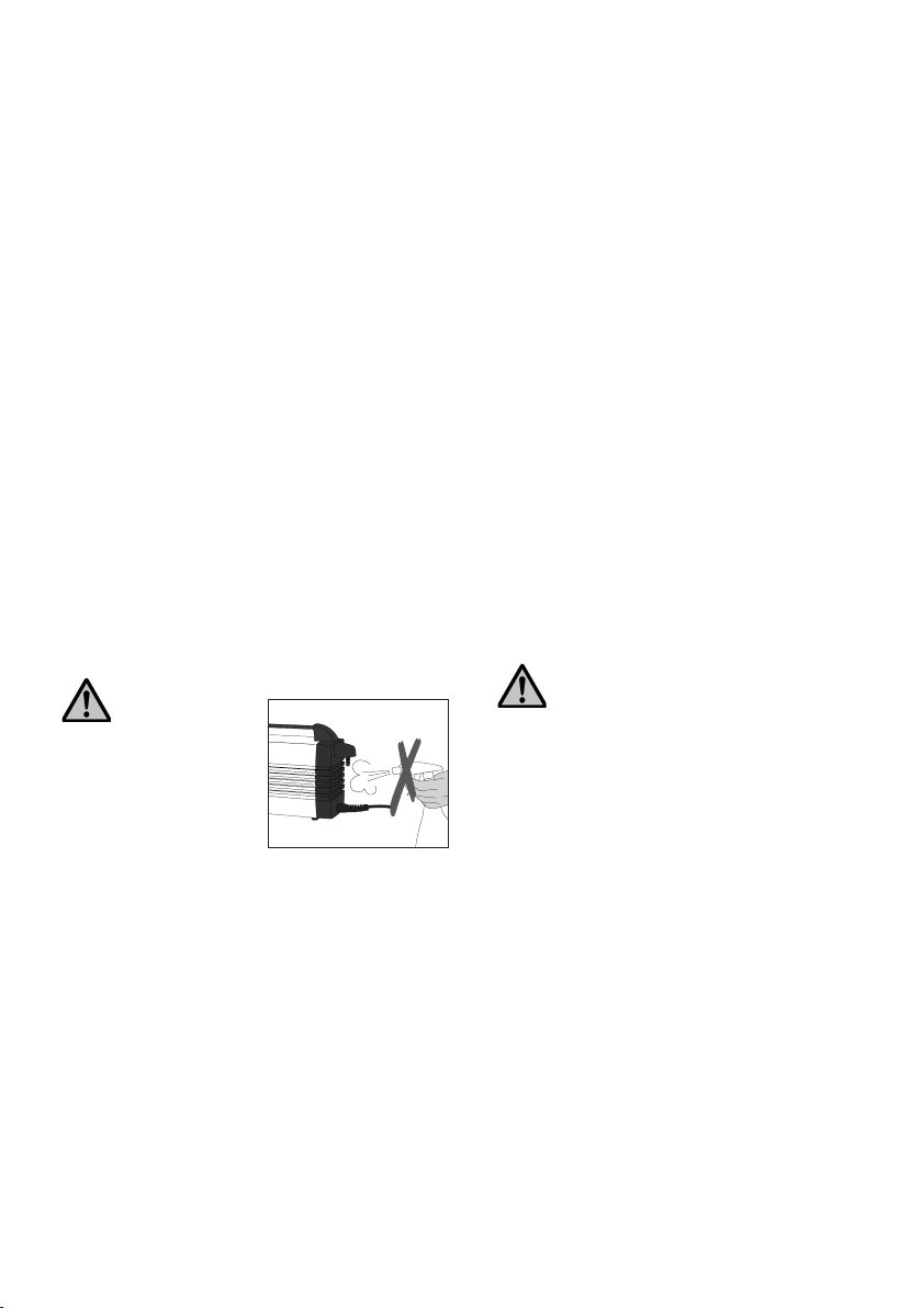
List of Parts
1 Cable connection with
bend protection
2 Power cord
3 Air vents
4 Vacuum hose
connection
5 Housing
6 Vacuum hose
7 Transportation grip
8 Sound absorber
9 Sound absorber
connection
10 Protective cap
11 Rating plate
12 Rubber feet
7
4
8
6
3
12
9
8
5
11
1
2
10
4
Page 5

1. Introduction / Signs and Symbols
1.1 Preface
Dear Customer
Thank you for having purchased the Programat® Vacuum
Pump. This apparatus is a high-quality, technical product.
Please read the Operating Instructions carefully and use
the apparatus according to the Instructions. Should you
have any further questions, please do not hesitate to
contact your local distributor or Ivoclar Vivadent AG
directly.
1.2 Introduction
Apparatus: Vacuum Pump VP5
Target group: Dental lab personnel
This vacuum pump is suitable for evacuating the firing
chamber of the Programat ceramic furnace. It is a quietly-running double-diaphragm pump with high vacuum
performance.
These Operating Instructions are designed to assure the
correct, safe, and economic use of the VP5 vacuum pump.
They are divided into several, clearly structured chapters to
help you find specific topics quickly and easily.
Signs and symbols (pictographs) are used to inform you
quickly and clearly about health risks, important details,
and contraindications.
We recommend keeping the Instructions in a safe place
near the pump so that they are immediately accessible if
necessary. Should you lose the Operating Instructions,
extra copies can be ordered at a nominal fee from your
local Ivoclar Vivadent Service Center or downladed from
www.ivoclarvivadent.com/downloadcenter.
1.3 Signs and symbols
The signs and symbols in these Operating Instructions and
on the pump facilitate the finding of important points and
have the following meanings:
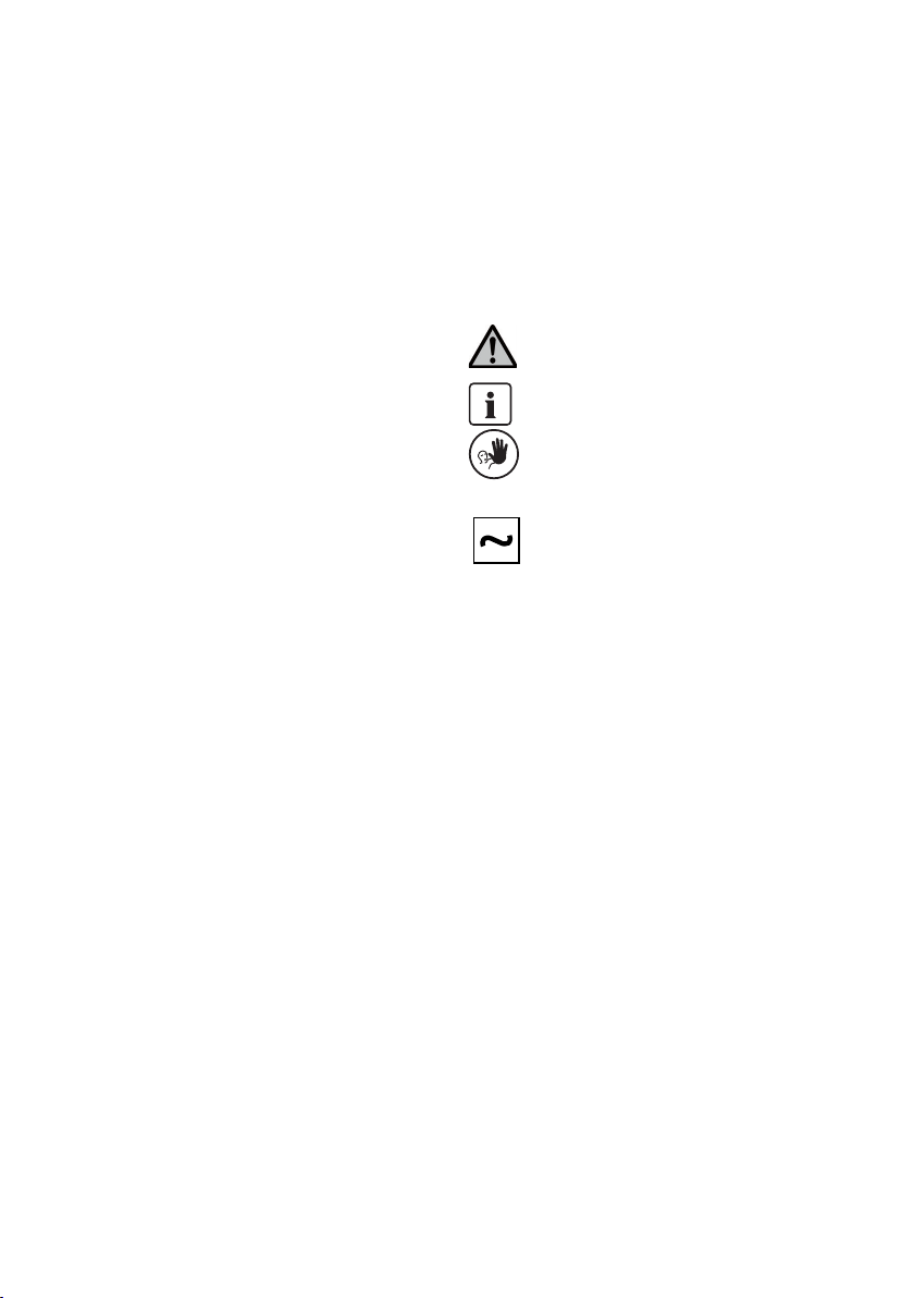
Operating Instructions:
Risks and dangers
Information
Contraindication
Pump:
Alternating current
5
Page 6
2. Safety First
This chapter is especially important for personnel who
work with the VP5 vacuum pump or who have to carry
out maintenance or repair work. This chapter must be
read and the corresponding instructions followed.
2.1 Indications
This vacuum pump has been developed especially for the
evacuation of Programat ceramic furnaces from Ivoclar
Vivadent and it should be used for this purpose only.
Other uses than the ones stipulated are contraindicated.
The manufacturer does not assume any liability for
damage resulting from misuse. The user is solely
responsible for any risk resulting from failure to observe
these instructions.
Further instructions to assure proper use of the pump:
– The instructions, regulations, and notes in the vacuum
pump's Operating Instructions must be observed.
– The pump must be operated under the indicated
environmental and operating conditions (Chapter 9).
– The VP5 must be properly maintained.
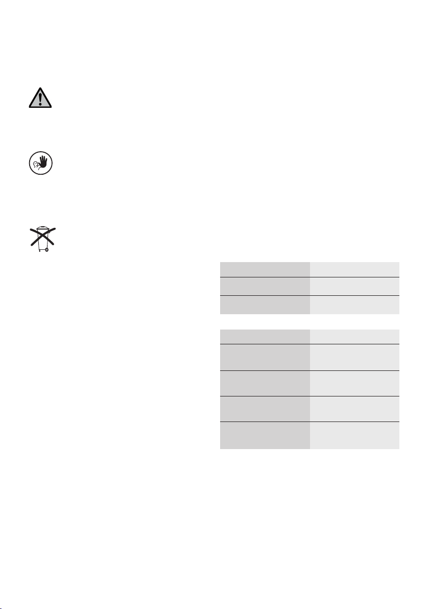
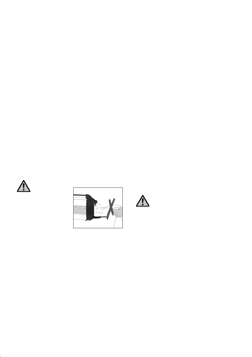
2.1.1
Risks and dangers
Foreign objects or liquids
must not enter the air vents,
since this may block the
motor or result in an
electrical shock.
2.2 Health and Safety Instructions
– Make sure that the pump is only used for the
indications stipulated in these Operating Instructions.
– Do not use the pump in areas where there is an
explosion hazard.
– Components connected with the pump must comply
with the pneumatic data of the pump.
– Observe the corresponding safety regulations when
connecting the pump to the power supply.
– If the operation of the pump is interrupted by the
thermoswitch because of over-heating, the pump
starts automatically once it has cooled down. Make
sure that no danger results from such an incidence.
– Use only original spare parts.
– The pump complies with the following directives:
– Directive 2006/42/EC on machinery
– Directive 2004/108/EC on electromagnetic
compatibility
– If the pump has been stored at very low temperatures
or high atmospheric humidity, the pump has to be
dried or left to adjust to the room temperature for
approx. 1 hour (do not connect to the power yet).
Do not work with liquids near the pump.
Should a liquid accidentally enter the pump,
disconnect the power and consult Customer
Service. Do not operate the pump.
– The pump is tested for use at altitudes of up to
2000 m above sea level.
– The pump may only be used indoors.
– The unit m ust not be technically modified.
6
Page 7
3. Product Description
Any disruption of the protective conductor
either inside or outside of the pump or any
loosening of the protective conductor connection
may lead to danger for the user in case of
mal fun ction. Deliberate interruptions are not
tolerated.
Do not use furnaces of other manu facturers that
are not coordinated with the pump. Ask the corresponding manufacturer for further details. The
vacuum pump has been especially developed for
use with the Programat ceramic furnaces and
must be used for this purpose only.
Disposal:
The pump must not be disposed of in the
normal domestic waste. Please correctly
dispose of old furnaces according to the
corresponding EU council directive.
Information regarding disposal may also be
found on the respective national Ivoclar
Vivadent homepage.
3.1 Components
The VP5 vacuum pump consists of the following
components:
– Vacuum pump with power cord
– Vacuum hose (accessory)
3.2 Functional description
The diaphragm squeezed between the cylinder head and
the housing is moved up and down by a con-rod. By
means of this movement and by suction and eduction
valves in the cylinder head, the firing and/or press chamber
of the furnace is evacuated and the vacuum is built up.
3.3 Hazardous areas and safety equipment
Description of the hazardous areas of the pump:
Hazardous area
Fuse holder
Ventilator
Safety equipment
Protective conductor
IP20 (protection type)
Thermoswitch
Ventilator cover
Type of risk
Electrical shock
Injury
Protective effect
Protection from electrical
shock
Protection from electrical
shock
Protection from
overheating
Protection from electrical
shock and injury
7
Page 8
4. Installation
4.1 Unpacking and checking the contents
Remove the pump from its packaging and check it for any
transportation damage. We recommend keeping the
original packaging for any transportation purposes. Use
only the original packaging for shipping.
4.2 Selecting the location
Place the pump on a flat surface using the rubber feet
(12). Make sure the pump is not exposed to direct sunlight. Do not place the pump in the immediate vicinity of
heaters or other sources of heat. Make sure that there is
enough space for air circulation between the wall and the
air vents (3).
Make sure to select the location in such a way that the
sound absorber is not knocked off by accidentally abutting
against laboratory furniture.
4.3 Making the connections
Checking the rating plate and power supply
Make sure that the voltage indicated on the rating plate
(11) complies with the local power supply. Should this not
be the case, do not connect the pump.
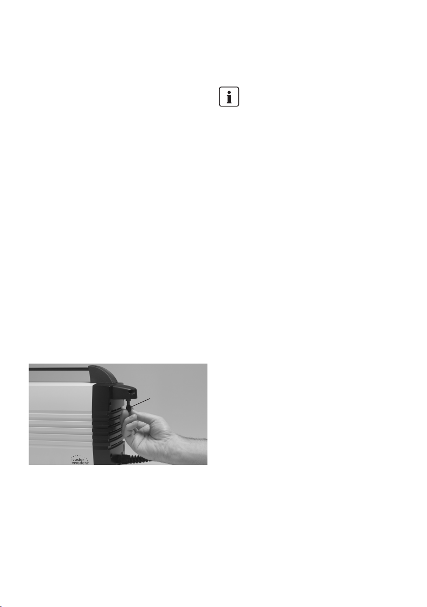
Connecting the vacuum hose
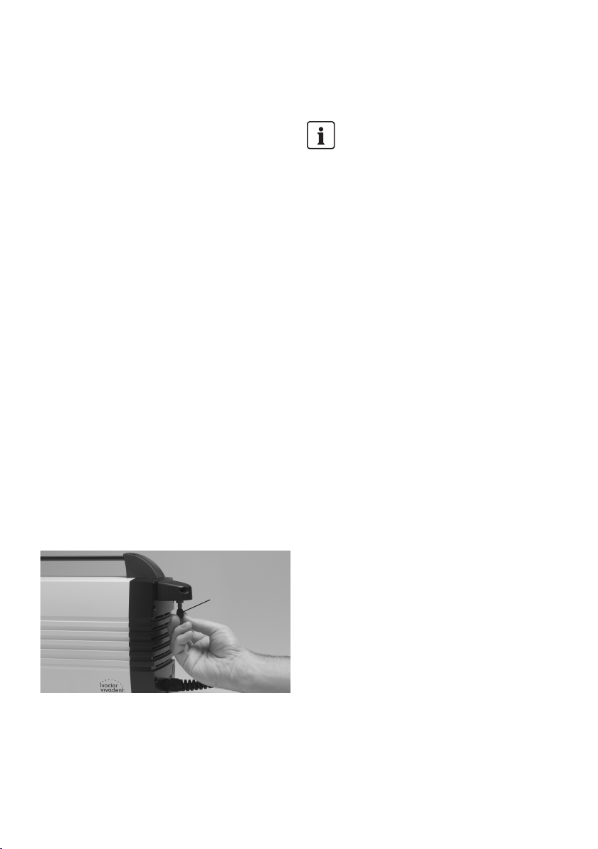
Remove the protective cap (10) from the vacuum hose
connection (4) and slip the vacuum hose on the vacuum
hose connection (4).
The electrical installation in the room where the
pump is used must comply with the local and IEC
requirements.
10
Connect the other end of the vacuum hose with the
furnace.
Please check if the hose is properly connected.
Connecting the power
Plug the power plug of the power cord (2) into the
corresponding socket in the Programat. This is the power
supply at the same time.
8
Page 9

5. Start-Up 6. Operation
The vacuum pump is automatically controlled by the
furnace, once the power cord of the pump has been
connected with the Programat furnace.
The pump is operated by the furnace programs.
9
Page 10

7. Maintenance and Cleaning
For safety reasons, disconnect power plug before
maintenance and cleaning.
7.1 Monitoring and maintenance
Basically, the diaphragm vacuum pump does not require
maintenance unless the performance deteriorates due to
contamination. Therefore, conduct a vacuum test at least
once a year.
The time for maintenance procedures depends on the
frequency of use and the location of the pump. For that
reason the recommended times are only approximates.
What
Check all plug-in
connections for
correct fit.
Check the hose
to make sure that
no condensation
water has
accumulated in
the system.
This apparatus has been developed for typical
use in the dental laboratory.
If the product is used in a production facility, for industrial
applications, or in continuous operation, premature ageing
of certain spare parts have to be expected.
These spare parts are e.g.:
– Sound absorber
– Diaphragm
– Valve reed
These spare parts are not covered by the warranty.
Please also observe the shorter service and maintenance
intervals.
Part
Connections
Vacuum hose
When
Weekly
Weekly
7.2 Cleaning
Remove dust from the pump from time to time. Use a
vacuum cleaner with a cleaning brush for that purpose.
Item
Housing
Sound absorber
(8)
Frequency
if required
if dirty
Cleaning material
soft, dry cloth
sound absorber
has to be
replaced
7.3 Notes on maintenance
The diaphragm may only be changed by an
Ivoclar Vivadent Service Center. The fuse must be
changed by qualified personnel.
Please observe the relevant rules and regu lations for the
prevention of accidents as well as the safety and medical
regulations.
10
Page 11

8. What If ...?
8.1 Technical malfunctions
Malfunction
1 The pump is not working
2 The vacuum performance is
declining or is bad
3 Vacuum pump is unusually noisy
Double-check
– Is the pump correctly connected?
– Has the thermoswitch been
activated because of overheating?
– Sound absorber clogged
– Has the test program for the
pump been carried out?
– Is the sound absorber defective or
incorrectly mounted?
– Is there a leak in the furnace sys-
tem or the pump?
Action
– Connect pump correctly.
– Allow the pump to cool and
switch on again.
– Check pump location for
adequate circulation of air.
– If the problem cannot be solved,
contact your local Ivoclar Vivadent
Service Center.
– Replace sound absorber.
– Carry out the test program for the
pump (PX1).
– Send vacuum pump to Service
Center for maintenance.
– Connect sound absorber correctly
or replace it, if it is defective.
– Check connections and hose for
tightness.
– Clean sealing of the furnace head.
– Check pump performance with
the corresponding test program.
8.2 Repairs
Repairs may only be carried out by the personnel of a certified
Ivoclar Vivadent Service Center. Please contact your Customer
Service representative.
11
Page 12
9. Product Specifications
9.1 Delivery form
– Vacuum pump VP5
– Operating Instructions
– Warranty Card
– Declaration of conformity
9.2 Technical data
Power supply: 230 V / 50–60 Hz / 0.40 A
200 V / 50–60 Hz / 0.50 A
115 V / 50–60 Hz / 0.85 A
100 V / 50–60 Hz / 0.95 A
Tolerated voltage fluctuations: +/– 10%
Power consumption: 80 W
Suction strength: 15 l / min.
Final vacuum
(measured with a 4-liter test container): approx. 20 mbar
Dimensions: 415 x 122 x 230 mm (length, width, height)
Weight: 8.0 kg
Types of fuses: 230 V: T 1.0 A 250 V
200 V: T 1.25 A 250 V
115 V: T 2.5 A 250 V
100 V: T 2,5 A 250 V
Safety information :
The pump complies with the following directives:
– Directive 2006/42/EC on machinery
– Directive 2004/108/EC on electromagnetic compatibility
9.3 Acceptable operating conditions
– Ambient temperature range of:
+5 °C to +40 °C (+41 °F to +104 °F)
– Acceptable height:
The pump is tested for use at altitudes of up to
2000 m above sea level.
– Pollution degree 2 Overvoltage category II
9.4 Acceptable transportation conditions
– Ambient temperature range of:
-10 °C to +55 °C (-4 °F to +131 °F)
– Maximum relative humidity: 80%
This apparatus has been developed for use in dentistry. Setup and
operation should be carried out strictly according to the Operating
Instructions. Liability cannot be accepted for damages resulting from
misuse or failure to observe the Instructions. The user is solely
responsible for testing the apparatus for its suitability for any
purpose not explicitly stated in the Instructions. Descriptions and
data constitute no warranty of attributes.
12
Page 13

Vakuumpumpe VP5
Seite
Teileverzeichnis 14
1. Einleitung und Zeichenerklärung 15
1.1 Vorwort
1.2 Einleitung
1.3 Zeichenerklärung
2. Sicherheit geht vor 16
2.1 Bestimmungsgemässe Verwendung
2.2 Sicherheits- und Gefahrenhinweise
3. Produktbeschreibung 17
3.1 Aufbau des Gerätes
3.2 Funktionsbeschreibung
3.3 Gefahrenstellen und Sicherheitseinrichtungen
4. Installation 18
4.1 Auspacken und Lieferumfang prüfen
4.2 Standortwahl
4.3 Anschlüsse herstellen
5. Inbetriebnahme 19
6. Bedienung 19
7. Unterhalt, Reinigung und Diagnose 20
7.1 Kontroll- und Unterhaltsarbeiten
7.2 Reinigungsarbeiten
7.3 Wartungshinweise
deutsch
8. Was ist, wenn... 21
8.1 Technische Störungen
8.2 Reparaturarbeiten
9. Produktspezifikationen 22
9.1 Lieferform
9.2 Technische Daten
9.3 Zulässige Betriebsbedingungen
9.4 Zulässige Transportbedingungen
13
Page 14

Teileverzeichnis
1 Kabelverschraubung
mit Knickschutz
2 Netzkabel
3 Lüftungsschlitze
4 Vakuumschlauch-
anschluss
5 Gehäuse
6 Vakuumschlauch
7 Transportgriff
8 Schalldämpfer
9 Schalldämpfer-
Anschluss
10 Schutzkappe
11 Typenschild
12 Gummifüsse
7
4
8
6
3
12
9
8
5
11
1
2
10
14
Page 15
1. Einleitung und Zeichenerklärung
1.1 Vorwort
Sehr geehrter Kunde
Es freut uns, dass Sie sich für den Kauf der ProgramatVakuumpumpe entschieden haben. Bei diesem Gerät
handelt es sich um ein technisch hochstehendes Produkt.
Wir bitten Sie, die Bedienungsanleitung zu lesen und das
Gerät analog der Bedienungsanleitung in Betrieb zu
nehmen.
Wenn Sie noch zusätzliche Fragen haben, wenden Sie sich
bitte an das entsprechende Depot oder direkt an
Ivoclar Vivadent.
1.2 Einleitung
Zutreffendes Gerät: Vakuumpumpe VP5
Zielgruppe: Zahntechnisches Fachpersonal
Diese Vakuumpumpe eignet sich für die Evakuierung der
Brennkammer beim Programat®-Keramikbrennofen. Bei
dieser Pumpe handelt es sich um eine Membranpumpe mit
guter Vakuumleistung und kompakten Abmessungen.
Die Bedienungsanleitung dient zur sicheren, sachgerechten und wirtschaftlichen Nutzung der Vakuumpumpe VP5.
Die Bedienungsanleitung ist in mehrere Kapitel unterteilt,
die klar gegliedert sind. Diese Aufteilung erleichtert ein
schnelles Auffinden der gewünschten Punkte.
Um Sie schnell und übersichtlich über Gefahren, wichtige
Informationen und nicht zulässige Anwendungen informieren zu können, werden an den Stellen entsprechende
Symbole (Piktogramme) verwendet.
Wir empfehlen Ihnen, die Bedienungsanleitung an einem
geschützten Ort in der Nähe des Gerätes aufzubewahren,
sodass jederzeit ein schneller Informationszugriff möglich
ist. Bei eventuellem Verlust kann die Bedienungsanleitung
gegen eine Schutzgebühr über die entsprechende Servicestelle bezogen oder im Download-Center unter
www.ivoclarvivadent.com/downloadcenter heruntergeladen werden.
1.3 Zeichenerklärung
Die Symbole in der Bedienungsanleitung erleichtern Ihnen
das Auffinden wichtiger Punkte und geben Ihnen folgende
Hinweise:
In der Bedienungs anleitung:
Gefahren mit Risiken
Informationen
Nicht zulässige Verwendungen
Auf dem Gerät:
Wechselstrom
15
Page 16
2. Sicherheit geht vor
Dieses Kapitel ist für alle Personen, die mit dem Gerät
arbeiten oder am Gerät Unterhalts- oder Reinigungs arbeiten
durchführen, zwingend zu lesen. Die Hinweise sind zu
befolgen.
2.1 Bestimmungsgemässe Verwendung
Die Vakuumpumpe wurde speziell für die Evakuierung der
Programat-Brennöfen von Ivoclar Vivadent entwickelt.
Bitte verwenden Sie dieses Gerät ausschliesslich für diesen
Zweck.
Eine andere oder darüber hinausgehende Benutzung gilt
als nicht bestimmungsgemäss. Für hieraus resultierende
Schäden haftet der Hersteller nicht. Das Risiko trägt allein
der Anwender.
Zur bestimmungsgemässen Anwendung gehören zudem:
– Die Beachtung der Anweisungen, Vorschriften und
Hinweise in der vorliegenden BA
– Der Betrieb unter den vorgeschriebenen Umwelt- und
Betriebsbedingungen (siehe Kapitel 9)
– Die korrekte Instandhaltung des Gerätes
2.1.1
Gefahren und Risiken
Es dürfen keine Gegenstände oder Flüssigkeiten in
die Lüftungsschlitze gelangen. Es könnte dadurch ein
Blockieren des Motors oder
ein Stromschlag verursacht
werden.
2.2 Sicherheits- und Gefahrenhinweise
– Beachten Sie, dass die Pumpe nur für den bestim-
mungsgemässen Gebrauch eingesetzt werden darf.
– Die Pumpen dürfen nicht in explosionsge fährdeter
Umgebung eingesetzt werden.
– Komponenten, die man an die Pumpe anschliesst,
müssen auf die pneumatischen Daten der Pumpen
ausgelegt sein.
– Beachten Sie beim Anschluss der Pumpen an das
Stromnetz die entsprechenden Sicherheitsregeln.
– Wird der Pumpenbetrieb durch den Thermoschutz-
schalter wegen Überhitzung unterbrochen, so startet
die Pumpe nach der Abkühlung automatisch. Sorgen
Sie dafür, dass hieraus keine Gefahrensituationen ent-
stehen können.
– Es dürfen nur Original-Ersatzteile verwendet werden.
– Die Pumpe entspricht folgenden Richtlinien:
– Richtlinie 2006/42/EG Maschinen
– Richtlinie 2004/108/EG über elektromagnetische Ver-
träglichkeit.
– Wurde das Gerät bei grosser Kälte oder bei hoher Luft-
feuchtigkeit gelagert, ist vor dem Anschluss an das
Stromnetz (ohne Spannung) die Pumpe bei Raumtem-
peratur einer Austrocknungszeit bzw. einer Tempera-
tur-Anpassungszeit von circa 1 Stunde zu unterziehen.
– Das Gerät ist in Höhen bis 2000 m N.N. geprüft.
– Das Gerät darf nur in Innenräumen verwendet werden.
– Es dürfen am Gerät keine technischen Veränderungen
Nicht in der Nähe des Gerätes mit Flüssigkeiten
hantieren. Sollte dennoch Flüssigkeit ins Gerät
gelangen, Stecker ziehen und den Kundendienst konsultieren. Gerät nicht wieder in
Betrieb setzen.
vorgenommen werden.
16
Page 17
3. Produktbeschreibung
Jegliche Unterbrechung des Schutzleiters inner-
halb oder ausserhalb des Gerätes oder das Lösen
des Schutzleiteranschlusses kann dazu führen,
dass bei einem auftretenden Fehler das Gerät für
den Betreiber eine Gefahr darstellt. Absichtliche
Unterbrechung ist nicht zulässig.
Verwenden Sie keine Fremdöfen, die nicht auf
das Gerät abgestimmt sind. Erkundigen Sie sich
dabei beim entsprechenden Hersteller.
Die Vakuumpumpe wurde speziell für die
Programat-Brennöfen entwickelt und darf nur für
die dafür bestimmten Zwecke verwendet werden.
Entsorgung:
Die Geräte dürfen nicht über den normalen
Hausmüll entsorgt werden. Bitte ausgediente
Geräte gemäss der EU-Richtlinie fachgerecht
entsorgen. Informationen zur Entsorgung finden
Sie auf der jeweiligen nationalen Ivoclar
Vivadent-Homepage.
.
3.1 Aufbau des Gerätes
Die Vakuumpumpe VP5 besteht aus folgenden
Komponenten:
– Vakuumpumpe mit Netzkabel
– Vakuumschlauch (Zubehör)
3.2 Funktionsbeschreibung
Die zwischen dem Zylinderkopf und dem Gehäuse eingeklemmte Membrane wird über einen Pleuel auf- und
abbewegt. Durch diese Bewegung und die Ein- und Auslassventile im Zylinderkopf wird die Luft aus der Brennbzw. Presskammer des Ofens abgesaugt, sodass ein
Vakuum entsteht.
3.3 Gefahrenstellen und Sicherheitseinrichtungen
Bezeichnung der Gefahrenstellen:
Gefahrenstelle
Sicherungshalter
Lüfterrad
Sicherheitseinrichtungen
Schutzleiter
IP20 (Schutzart)
Thermoschutzschalter
Abdeckung Lüfterrad
Art der Gefährdung
Stromschlag
Verletzung
Schutzwirkung
Schutz vor Stromschlag
Schutz vor Stromschlag
Schützt Pumpe vor
Überlastung
Schutz vor Stromschlag
und Verletzung
17
Page 18
4. Installation
4.1 Auspacken und Lieferumfang prüfen
Gerät aus der Verpackung nehmen und auf eventuelle
Transportschäden überprüfen. Wir empfehlen, dass Sie die
Originalverpackung für eventuelle Versandzwecke aufbewahren. Für den Versand verwenden Sie bitte nur die
Originalverpackung.
4.2 Standortwahl
Stellen Sie das Gerät mit den Gummifüssen (12) auf eine
ebene Ablagefläche. Achten Sie darauf, dass das Gerät
nicht einer direkten Sonnenbestrahlung ausgesetzt ist.
Stellen Sie das Gerät nicht in unmittelbare Nähe von Heizkörpern oder anderen Wärmequellen. Beachten Sie, dass
zwischen Wand und Lüftungsschlitzen (3) genügend
Abstand für die Luftzirkulation vorhanden ist. Achten Sie
beim Aufstellen auch darauf, dass der Platz so gewählt
wird, dass der Schalldämpfer durch das versehentliche
Anstossen an Labormöbeln nicht abgeschlagen werden
kann.
4.3 Anschlüsse herstellen
Typenschild mit Spannung überprüfen
Bitte prüfen Sie, ob die auf dem Typenschild (11) angegebene Spannung mit derjenigen Ihres Netzes übereinstimmt. Sollte dies nicht der Fall sein, darf das Gerät nicht
angeschlossen werden.
Vakuumschlauch anschliessen
Die Schutzkappe (10) des Vakuum schlauch-Anschlusses (4)
entfernen und den Vakuumschlauch auf den Vakuumschlauch-Anschluss (4) stecken.
Die elektrischen Installationen des Raumes, in
dem sich das Gerät befindet, müssen den landesüblichen und den IEC-Normen entsprechen.
10
Das andere Schlauchende mit dem Ofen verbinden.
Bitte prüfen Sie, ob der Schlauch einwandfrei aufgesteckt
ist.
Netzanschluss herstellen
Netzstecker des Netzkabels (2) in die ent sprechende
Gerätesteckdose des Programats stecken. Dies ist zugleich
der Netzanschluss.
18
Page 19

5. Inbetriebnahme 6. Bedienung
Die Vakuumpumpe wird automatisch über den Ofen
angesteuert, wenn Sie das Netzkabel der Pumpe mit
dem Programat-Ofen verbinden.
Die Bedienung erfolgt über das Ofenprogramm.
19
Page 20

7. Unterhalt, Reinigung und Diagnose
Aus sicherheitstechnischen Gründen bei sämt-
lichen Wartungs- und Reinigungsarbeiten den
Netz stecker aus der Gerätesteckdose ziehen.
7.1 Kontroll- und Unterhaltsarbeiten
Die Membran-Vakuumpumpe benötigt grundsätzlich keine
Wartung, ausser die Leistung der Vakuumpumpe verschlechtert sich durch Verschmutzung. Führen Sie aus diesem Grund mindestens einmal pro Jahr einen Vakuumtest
aus.
Wann eine Wartungsarbeit durchgeführt werden soll,
hängt stark von der Gebrauchsintensität und dem Standort der Pumpe ab. Aus diesem Grund stellen die empfohlenen Werte nur Richtwerte dar.
Was
Prüfen Sie, ob die
Steckverbindung
einwandfrei ist
Überprüfen Sie
den Schlauch,
damit kein Kondenswasser im
Leitungssystem
ist
Dieses Gerät ist für den typischen Einsatz im
Detallabor entwickelt worden.
Teil
Stecker
Vakuumschlauch
Wann
wöchentlich
wöchentlich
7.2 Reinigungsarbeiten
Die Pumpe gelegentlich von Staub befreien.
Verwenden Sie dazu zum Beispiel einen Staubsauger mit
Reinigungspinsel.
Was
Gehäuse
Schalldämpfer (8)
Wann
nach Bedarf
bei starker Verschmutzung
Mit was
mit trockenem,
weichem Lappen
austauschen
7.3 Wartungshinweise
Der Membranwechsel darf nur von einer Ivoclar
Vivadent-Servicestelle durchgeführt werden. Der
Sicherungswechsel darf nur durch Fachpersonal
erfolgen.
Beachten Sie bitte die einschlägigen Unfallverhütungsvorschriften sowie die sonstigen anerkannten sicherheitstechnischen und arbeitsmedizinischen Regeln.
Falls das Produkt in einem Produktionsbetrieb, einer Industrieanwendung oder im Dauerbetrieb eingesetzt wird,
muss mit einer vorzeitigen Alterung bzw. Verschmutzung
gerechnet werden.
Verschleissteile sind z. B.:
– Schalldämpfer
– Strukturmembrane
– Ventilplatte
Verschleissteile sind von der Garantieleistung ausgenommen. Bitte beachten Sie dazu auch die verkürzten
Service- und Wartungsintervalle.
20
Page 21

8. Was ist, wenn ...?
8.1 Technische Störungen
Fehlerbeschreibung
1 Pumpe läuft nicht
2 Vakuumleistung verschlechtert
sich oder ist schlecht
3 Vakuumpumpe erzeugt unge-
wöhnlich hohen Lärmpegel
Hinweise für den Anwender
– Ist die Pumpe richtig
angeschlossen?
– Hat der Thermoschalter wegen
Überhitzung angesprochen?
– Schalldämpfer verstopft
– Wurde das Pumpen-Testpro-
gramm durchgeführt?
– Ist der Schalldämpfer defekt oder
nicht richtig montiert?
– Ist im Ofensystem oder in der
Pumpe ein Leck vorhanden?
Massnahme
– Pumpe richtig anschliessen.
– Pumpe abkühlen lassen und noch-
mals einschalten.
– Pumpenstandort auf ausreichende
Belüftung überprüfen.
– Falls das Problem nicht gelöst wer-
den kann, muss die zuständige
Servicestelle kontaktiert werden.
– Schalldämpfer austauschen.
– Pumpen-Testprogramm
durchführen.
– Vakuumpumpe zur Wartung an
Servicestelle senden.
– Schalldämpfer richtig aufschrau-
ben oder bei Defekt ersetzen.
– Anschlüsse und Schlauch auf
Dichtheit prüfen.
– Ofenkopfdichtung reinigen.
– Pumpenleistung mit dem
Testprogramm überprüfen.
8.2 Reparaturarbeiten
Reparaturarbeiten dürfen nur von einer qualifizierten Ivoclar
Vivadent-Servicestelle durchgeführt werden. Bitte wenden Sie
sich diesbezüglich an den Kundenservice.
21
Page 22

9. Produktspezifikationen
9.1 Lieferform
– Vakuumpumpe VP5
– Bedienungsanleitung
– Garantieschein
– Konformitätserklärung
9.2 Technische Daten
Netzanschluss: 230 V / 50–60 Hz / 0,40 A
200 V / 50–60 Hz / 0,50 A
115 V / 50–60 Hz / 0,85 A
100 V / 50–60 Hz / 0,95 A
Zulässige Spannungsschwankungen: +/– 10 %
Leistungsaufnahme: 80 W
Saugvermögen: 15 l / min.
Endvakuum
(gemessen mit 4 Liter Prüfbehälter): ca. 20 mbar
Masse: 415 x 122 x 230 mm (Länge, Breite, Höhe)
Gewicht: 8,0 kg
Sicherungstyp: 230 V: T 1,0 A 250 V
200 V: T 1,25 A 250 V
115 V: T 2,5 A 250 V
100 V: T 2,5 A 250 V
Sicherheitshinweise:
Die Pumpe entspricht folgenden Richtlinien:
– Richtlinie 2006/42/EG Maschinen
– Richtlinie 2004/108/EG über elektromagnetische Ver-
träglichkeit.
9.3 Zulässige Betriebsbedingungen
– Umgebungstemperatur im Betrieb: +5 °C bis +40 °C
– Zulässige Höhe:
Das Gerät ist für Höhen bis 2000 m geprüft.
– Verschmutzungsgrad 2
Überspannungskategorie II
9.4 Zulässige Transportbedingungen
– Umgebungstemperaturbereich: -10 °C bis +55 °C
– Maximale relative Feuchte: 80 %
Das Gerät wurde für den Einsatz im Dentalbereich entwickelt. Inbe-
triebnahme und Bedienung müssen gemäss Bedienungsanleitung
erfolgen. Für Schäden, die sich aus anderweitiger Verwendung oder
nicht sachgemässer Handhabung ergeben, übernimmt der Hersteller
keine Haftung. Darüber hinaus ist der Benutzer verpflichtet, das
Gerät eigenverantwortlich vor Gebrauch auf Eignung und Einsetzbarkeit für die vorgesehenen Zwecke zu prüfen, zumal wenn diese
Zwecke nicht in der Bedienungsanleitung aufgeführt sind.
22
Page 23

Pompe à vide VP5
Page
Désignation des pièces 24
1. Introduction et explication des symboles 25
1.1 Préambule
1.2 Introduction
1.3 Explication des symboles
2. La sécurité avant tout 26
2.1 Utilisation appropriée
2.2 Consignes en matière de sécurité et de risque
3. Désignation du produit 27
3.1 Conception de l‘appareil
3.2 Description du fonctionnement
3.3 Zones de danger et dispositifs de sécurité
4. Installation 28
4.1 Déballage et contrôle de la livraison
4.2 Choix de l‘emplacement
4.3 Branchement
4.4 Montage du silencieux
5. Mise en service 29
6. Utilisation 29
7. Entretien, Nettoyage et Diagnostics 30
7.1 Travaux de contrôle et d‘entretien
7.2 Travaux de nettoyage
7.3 Notices d‘entretien
français
8. Que faire si... 31
8.1 Défaillance technique
8.2 Travaux de réparation
9. Spécifications du produit 32
9.1 Présentation
9.2 Fiche technique
9.3 Conditions d‘utilisation admises
9.4 Conditions de transport
23
Page 24

Désignation des pièces
1 raccord du câble avec
protection contre le
pliage
2 câble secteur
3 fentes d‘aération
4 raccord du tuyau de
pompe
5 carter
6 tuyau de connexion
7 poignée de transport
8 silencieux
9 raccord du silencieux
10 capuchon de
protection
11 plaque constructeur
12 pieds en caoutchouc
7
4
8
6
3
12
9
8
5
11
1
2
10
24
Page 25

1. Introduction et explication des symboles
1.1 Préambule
Cher Client
Nous sommes très heureux que vous ayez choisi une
pompe à vide Programat®. Il s‘agit ici d‘un appareil d‘une
grande qualité technique. Aussi, nous vous demandons de
bien lire le mode d‘emploi et d‘utiliser l‘appareil
correctement.
Si vous avez d‘autres questions, n‘hésitez pas à contacter
votre Dépôt ou directement Ivoclar Vivadent.
1.2 Introduction
Appareil concerné: Pompe à vide VP5
Groupe d‘utilisateurs: Personnel qualifié en prothèse
dentaire
Cette pompe à vide est adaptée à l‘évacuation de l‘air de
la chambre de cuisson des fours à céramique Programat. Il
s‘agit ici d‘une pompe à membrane ayant une capacité de
vide élevée et un encombrement réduit.
Le mode d‘emploi (ME) permet un usage sûr, fonctionnel
et économique de la pompe VP5.
Le ME est divisé en plusieurs chapitres clairement désignés,
ce qui permet de retrouver rapidement les sujets
souhaités.
Pour attirer votre attention rapidement et clairement sur
les dangers, les informations importantes et les utilisations
non autorisées, les symboles (pictogrammes)
correspondants seront indiqués à l‘endroit voulu.
Nous vous recommandons de garder le ME dans un
endroit protégé à proximité de l‘appareil afin de pouvoir y
accéder rapidement. En cas de perte du mode d’emploi,
ce dernier peut être commandé auprès du service aprèsvente, ou vous pouvez le télécharger sur le site internet :
www.ivoclarvivadent.com/ downloadcenter.
1.3 Explication des symboles
Les symboles contenus dans ce mode d‘emploi vous
facilitent la recherche des points importants et vous
donnent les informations suivantes :
Dans le Mode d‘emploi :
Risques de danger
Informations
Utilisation non Autorisée
Sur l‘ Appareil :
Courant alternatif
25
Page 26

2. La sécurité avant tout
Ce chapitre est à lire obligatoirement par toutes les
personnes qui travaillent avec l‘appareil ou qui effectuent
des travaux d‘entretien ou de réparation. Les indications
sont à suivre.
2.1 Utilisation appropriée
La pompe à vide a été spécialement conçue pour
l‘évacuation de l‘air des fours de cuisson Programat
Ivoclar Vivadent. Veuillez utiliser cet appareil uniquement
pour cet effet.
Une autre utilisation ou allant au-delà de cette indication
est considérée comme inappropriée. Le fabricant n‘est pas
responsable des dommages résultant d‘une telle
utilisation. Le risque est supporté uniquement par
l‘utilisateur.
Une utilisation appropriée comprend en outre:
– le respect des instructions, des prescriptions et des
informations contenues dans le présent ME
– l‘utilisation suivant les conditions d‘environnement et
de fonctionnement de rigueur (voir chapitre 9)
– l‘entretien correct de l‘appareil
2.1.1
Risques de danger
Aucun objet ou liquide ne
doit parvenir dans les évents
d‘aération. Cela pourrait
bloquer le moteur ou
occasionner une décharge
électrique.
2.2 Consignes en matière de sécurité et de risque
– veillez à ce que la pompe soit utilisée uniquement
d‘après les prescriptions
– la pompe ne doit pas être installée dans un endroit où
il y a un risque d‘explosion
– les éléments sur lesquels la pompe est branchée
doivent correspondre aux données pneumatiques de
celle-ci
– respecter les règles de sécurité correspondantes lors du
branchement de la pompe au réseau électrique
– si le fonctionnement de la pompe est interrompu à la
suite du déclenchement du disjoncteur thermique à
cause d‘une surchauffe, la pompe se réactive automatiquement après refroidissement. Veillez à ce que
ce mode de fonctionnement n‘entraîne pas de
situation de danger.
– utiliser uniquement des pièces de rechange d‘origine
– la pompe est conforme aux directives suivantes :
– Directive 2006/42/EC sur les machines
– Directive 2004/108/EC sur la compatibilité électro-
magnétique
– si l‘appareil a été stocké par grand froid ou humidité
élevée, avant son utilisation, il faudra le laisser sécher
ou le laisser à température ambiante pendant 1 heure
environ (hors tension)
Ne pas manipuler de liquide au-dessus de
l‘appareil. Si toutefois, du liquide parvenait à
s‘introduire dans celui-ci, débrancher l‘appareil du
secteur et consulter le service après-vente. Ne plus
mettre l‘appareil en marche.
– l‘appareil est contrôlé jusqu‘à 2000 m au-dessus du
niveau de la mer.
– l‘appareil ne doit être utilisé qu‘à l‘intérieur.
– l‘appareil ne doit pas subir de modifications
techniques.
26
Page 27

3. Description du produit
Toute interruption du fil de protection terre à
l‘intérieur ou à l‘extérieur de l‘appareil ou le
détachement du fil de protection terre peut
représenter un danger pour l‘utilisateur en cas de
panne. Une interruption volontaire n‘est pas
admise.
Ne pas utiliser d‘autres fours qui ne sont pas
adaptés à la pompe. Renseignez-vous auprès du
fabricant. La pompe à vide a été conçue spécialement pour les fours de cuisson Programat et doit
uniquement être utilisée pour les usages prévus à
cet effet.
Elimination en fin de vie :
L’appareil ne peut être jeté avec les ordures
ménagères. L’appareil usagé doit être recyclé
par des professionnels selon la directive CE.
Vous trouverez de plus amples informations
sur le traitement des déchets sur la page
d’accueil du site Ivoclar Vivadent de votre
pays.
3.1 Conception de l‘appareil
La pompe à vide VP5 est composée de :
– pompe à vide avec câble secteur
– tuyau (accessoire)
3.2 Description du fonctionnement
La membrane située entre la tête du cylindre et le carter
est activée de haut en bas par une bielle. Grâce aux valves
d‘entrée et de sortie placées dans la tête du cylindre l‘air
de la chambre de chauffe du four est aspiré, créant ainsi le
vide.
3.3 Zones de danger et dispositifs de sécurité
Désignation des endroits dangereux :
Endroits dangereux
porte-fusibles
ventilateur
Dispositifs de sécurité
fil de protection terre
IP20 (type de protection)
Disjoncteur thermique
Cache de ventilateur
Types de danger
décharge électrique
blessure
Type de protection
protection contre la
décharge électrique
protection contre la
décharge électrique
protège la pompe de
surcharge
protection contre la
décharge électrique et la
blessure
27
Page 28

4. Installation
4.1 Déballage et contrôle de la livraison
Sortir l‘appareil de son emballage et contrôler son bon
état. Nous vous conseillons de conserver l‘emballage
d‘origine et de l‘utiliser pour tout envoi éventuel.
4.2 Choix de l‘emplacement
Positionner les pieds en caoutchouc (12) de l‘appareil sur
une surface plate. Veiller à ce que celui-ci ne soit pas
exposé directement aux rayons solaires. Ne pas installer
l‘appareil à proximité de radiateurs ou de toute autre
source de chaleur.
Veiller à ce qu‘il y ait suffisamment d‘espace pour la
circulation de l‘air entre le mur et les fentes d‘aération (3).
Faire attention aussi à ce que l‘emplacement choisi
n‘expose pas le silencieux à un risque de détachement
ou de cassure.
4.3 Branchement
Contrôle du voltage indiqué sur la plaque signalétique
Vérifier que la tension indiquée sur la plaque signalétique
(11) corresponde bien à celle du secteur. Le cas échéant,
ne pas brancher l‘appareil.
Branchement du tuyau de vide
Retirer les protecteurs (10) du raccord du tuyau de la
pompe (4) et pousser le tuyau de la pompe sur le raccord
de celui-ci.
Les installations électriques de la pièce où se
trouve l‘appareil doivent être conformes aux
normes en vigueur du pays et aux normes IEC.
10
Relier l‘autre extrémité du tuyau au four.
Contrôler si le tuyau est enfoncé correctement.
Branchement au secteur
Introduire la fiche de branchement de la pompe (2) du
câble secteur (3) dans la prise de courant correspondante
du Programat.
28
Page 29

5. Mise en service 6. Utilisation
La pompe à vide est activée automatiquement par le four
si vous reliez le câble secteur de la pompe avec le four.
L‘utilisation s‘effectue par le programme du four
29
Page 30

7. Entretien, nettoyage et diagnostics
Pour des raisons techniques de sécurité, il est
obligatoire de retirer la fiche de branchement (2)
de la pompe de la prise de courant de l‘appareil
pour tous les travaux de maintenance
et d‘entretien.
7.1 Travaux de contrôle et d‘entretien
La membrane de la pompe à vide ne nécessite aucune
maintenance, à moins que la performance de la pompe se
détériore par salissure. Pour cette raison réalisez au moins
une fois par an un test de vide.
La périodicité des travaux d‘entretien dépend de l‘intensité
d‘utilisation et de l‘emplacement de la pompe. De ce fait,
les valeurs indiquées sont données à titre d‘orientation.
Quoi
Vérifier si le
branchement
secteur est en
bon état
Vérifier le tuyau
afin qu’il n’y ait
pas d’eau de
condensation
dans le circuit
Cet appareil a été conçu pour une utilisation bien
définie au laboratoire de prothèse dentaire.
Partie
Fiche de
l’appareil
Tuyau de pompe
Quand
hebdomadaire
hebdomadaire
7.2 Travaux de nettoyage
Dépoussiérer de temps en temps la pompe en utilisant par
ex. un aspirateur avec un pinceau de nettoyage.
Quoi
carter
silencieux (8)
Quand
si nécessaire
souillure
importante
Moyens
chiffon sec et
doux
remplacer
7.3 Notice d‘entretien
Le changement de la membrane ne peut être
effectué que par le Service technique Ivoclar
Vivadent. Le remplacement des fusibles ne peut
être fait que par du personnel qualifié.
Respecter les prescriptions de prévention des accidents
ainsi que les autres règles techniques de sécurité et de
médecine du travail.
Pour le cas où cet appareil est utilisé dans une entreprise
de production, pour une application industrielle ou en
fonctionnement continue, il faut s‘attendre à un
vieillissement précoce et/ou à une salissure plus
importante.
Des pièces d‘usure sont p. ex. :
– silencieux
– membrane
– plaque de valves
Les pièces d‘usure sont exclues de la garantie. Respecter
aussi dans ce contexte les intervalles raccourcis de service
et d‘entretien.
30
Page 31

8. Que faire si ...
8.1 Défaillance technique
Description des erreurs
1 La pompe ne fonctionne pas
2 La capacité du vide est altérée ou
est de mauvaise qualité
3 Le niveau sonore de la pompe est
trop élevé
Indication pour l’utilisateur
– Est-ce que la pompe est bien
branchée?
– Le disjoncteur thermique de surch-
auffe s’est-il déclenché?
– le silencieux est obstrué
– Est-ce que le programme-test de
la pompe a été effectué?
– Est-ce que le silencieux n’est-il pas
défectueux et est-il monté
correctement?
– Y a t-il une fuite dans le système
du four ou dans la pompe?
Mesures
– Bien brancher la pompe.
– Laisser refroidir la pompe et
allumer à nouveau.
– Contrôler que l’endroit où est
installée la pompe soit
suffisamment aéré.
– Si le problème ne peut être résolu,
contacter le Service technique
responsable.
– remplacer le silencieux.
– Effectuer le programme test de la
pompe
– Envoyer la pompe au Service
Technique pour maintenane
– Visser correctement le silencieux
ou le remplacer s’il est défectueux
– Contrôler l’étanchéité des raccords
et du tuyau.
– Nettoyer le joint du couvercle du
four.
– Contrôler la capacité de la pompe
en effectuant le programme-test
8.2 Travaux de réparation
Les travaux de réparation ne doivent être réalisés que par un
Service technique qualifié Ivoclar Vivadent. Veuillez vous adresser
pour cela au Service clientèle.
31
Page 32

9. Spécifications du produit
9.1 Présentation
– pompe à vide VP5
– mode d‘emploi
– bon de garantie
– certificat de conformité
9.2 Fiche technique
Branchement au secteur : 230 V / 50–60 Hz / 0,40 A
200 V / 50–60 Hz / 0,50 A
115 V / 50–60 Hz / 0,85 A
100 V / 50–60 Hz / 0,95 A
Variations de tension admise : +/– 10%
Puissance absorbée : 80 W
Capacité d‘aspiration : 15 l / min.
Vide final (mesuré avec un contenant
de test de 4 l ) : env. 20 mbar
Encombrement : 415 x 122 x 230 mm
(Longueur, largeur, hauteur)
Poids : 8,0 kg
Fusibles : 230 V: T 1,0 A 250 V
200 V: T 1,25 A 250 V
115 V: T 2,5 A 250 V
100 V: T 2,5 A 250 V
Recommandation de sécurité :
La pompe est conforme aux directives suivantes :
– Directive 2006/42/EC sur les machines
– Directive 2004/108/EC sur la compatibilité
électromagnétique
9.3 Conditions d‘utilisation admises
– Température ambiante au moment de l‘utilisation :
+5 °C à +40 °C
– Hauteur admise :
L‘appareil a été testé à une altitude jusqu‘à 2000 m
– Indice de pollution 2
Indice de protection II
9.4 Conditions de transport et de stockage
– Température ambiante de : -10 °C à +55 °C
– Humidité relative de l‘air max. : 80%
Cet appareil a été développé pour un usage dans le domaine den-
taire. La mise en service et l‘utilisation doivent s‘effectuer conformément au mode d‘emploi. L‘utilisation de l‘appareil pour un usage
autre que celui mentionné dans la documentation et le mode d‘emploi est à proscrire. Les dommages résultant du non-respect de ces
prescriptions ou d‘une utilisation à d‘autres fins que celles indiquées
n‘engagent pas la responsabilité du fabricant. L‘utilisateur est tenu
de vérifier sous sa propre responsabilité l‘appropriation de l‘appareil
à l‘utilisation prévue et ce d‘autant plus si celle-ci n‘est pas citée dans
le mode d‘emploi.
32
Page 33

Pompa per il vuoto VP5
Pag.
Elenco particolari 34
1. Introduzione e descrizione dei simboli 35
1.1 Premessa
1.2 Introduzione
1.3 Descrizione dei simboli
2. La sicurezza innanzitutto 36
2.1 Utilizzo secondo le prescrizioni
2.2 Avvertenze di sicurezza e di pericolo
3. Descrizione prodotto 37
3.1 Costruzione dell‘apparecchio
3.2 Descrizione delle funzioni
3.3 Indicazioni di pericolo e protezioni
4. Installazione 38
4.1 Disimballaggio e controllo del contenuto
4.2 Scelta del luogo d‘installazione
4.3 Montaggio ed allacciamenti
4.4 Montaggio del silenziatore
5. Messa in funzione 39
6. Utilizzo pratico 39
7. Manutenzione, pulizia e diagnosi 40
7.1 Lavori di manutenzione e di controllo
7.2 Pulizia dell’apparecchio
7.3 Avvertenze di manutenzione
italiano
8. Cosa succede, se... 41
8.1 Disturbi tecnici
8.2 Riparazioni
9. Specifiche del prodotto 42
9.1 Presentazione
9.2 Dati tecnici
9.3 Condizioni ammesse per il funzionamento
9.4 Condizioni ammesse per il trasporto
33
Page 34

Elenco particolari
1 avvitamento cavo con
protezione
2 cavo di allacciamento
3 fessure di areazione
4 allacciamento tubo del
vuoto
5 intelaiatura
6 tubo di collegamento
7 maniglia per il
trasporto
8 silenziatore
9 collegamento per
silenziatore
10 cappuccio di
protezione
11 targhetta
12 piedini
7
4
8
12
5
11
1
6
3
2
9
8
34
10
Page 35

1. Introduzione e descrizione dei simboli
1.1 Premessa
Egregio Cliente
Siamo lieti che abbia acquistato una pompa per il vuoto
Programat®. Questo apparecchio è un prodotto di elevata
tecnologia. La preghiamo di leggere le istruzioni d’uso e di
impiegare l’apparecchio secondo quanto riportato in esse.
Nel caso abbia ulteriori domande in merito, la preghiamo
di rivolgersi al Suo concessionario di fiducia o direttamente
alla Ivoclar Vivadent.
1.2 Introduzione
Apparecchio: Pompa per il vuoto VP5
Destinatari: personale odontotecnico
qualificato
La presente pompa per il vuoto è indicata per l’evacuazione della camera di cottura dei forni per cottura di
ceramica Programat®. Si tratta di una pompa a membrana
di elevata capacità.
Le istruzioni d’uso servono ad un impiego sicuro, corretto
ed economico della pompa VP5. Le istruzioni d‘uso sono
suddivise in diversi capitoli. In questo modo è possibile
una ricerca veloce dei diversi temi contenuti.
Per poter informare in modo veloce e chiaro sui pericoli,
informazioni importanti ed impieghi non ammessi,
vengono utilizzati i relativi simboli (pittogrammi).
Le consigliamo di conservare le istruzioni d’uso in luogo
protetto nelle vicinanze del forno, in modo da averle
sempre a portata di mano per ogni consultazione. In caso
di smarrimento delle istru zioni d’uso, La preghiamo di
rivolgersi al Servizio Assistenza Ivoclar che provvederà
all’inoltro oppure potrà scaricarle dal nostro Download-
Center dal sito www.ivoclarvivadent.com/ downloadcenter.
1.3 Descrizione dei simboli
I simboli riportati nelle istruzioni d‘uso e sull‘apparecchio
facilitano la ricerca di punti importanti ed hanno il
seguente significato:
Nelle istruzioni d’uso:
Pericoli con rischi
Informazioni
Impieghi non ammessi
Sull’apparecchio:
Corrente alternata
35
Page 36

2. La sicurezza innanzitutto
Questo capitolo deve essere letto da tutte le persone che
lavorano con l‘appareccchio o che eseguono lavori di
manutenzione o pulizia. E‘ assolutamente necessario
attenersi alle indicazioni ed avvertenze!
2.1 Utilizzo secondo le prescrizioni
La pompa per il vuoto VP5 è stata espressamente
sviluppata per l’evacuazione dei forni per cottura di
ceramica Programat della Ivoclar Vivadent. Si prega di
utilizzare questo apparecchio soltanto per questo scopo.
Un impiego diverso, corrisponde ad un uso non conforme.
Per i danni che ne derivano il produttore non è
responsabile. Il rischio è ad esclusivo carico dell‘utilizzatore.
Per un uso corretto sono necessari inoltre:
– L‘osservanza delle avvertenze, indicazioni e prescrizioni
della presente istruzione d‘uso.
– L‘impiego in osservanza delle normative ambientali e
di utilizzo (vedi capitolo 9).
– La corretta manutenzione dell’apparecchio.
2.1.1
Pericoli e rischi
Non devono penetrare corpi
estranei o liquidi nelle
fessure di areazione. In tal
caso si potrebbe causare un
blocco del motore o una
scarica di corrente.
2.2 Avvertenze di sicurezza e di pericolo
– Consideri che l’apparecchio può essere impiegato
soltanto per l’uso previsto
– La pompa non deve essere impiegata in ambiente
esposto a pericolo di esplosioni.
– Componenti che si collegano alla pompa devono
corrispondere ai dati pneumatici della pompa.
– Nell’allacciamento della pompa alla rete elettrica,
osservare le relative regole di sicurezza.
– Se il funzionamento della pompa viene interrotto
dall’interruttore di sicurezza termica a causa di
surriscaldamento, dopo il raffreddamento la pompa si
riavvia automaticamente. Provvedere affinché in questi
casi non nascano situazioni di pericolo.
– Possono essere utilizzati soltanto ricambi originali.
– La pompa corrisponde alle seguenti direttive:
– Direttiva 2006/42/CE macchine
– Direttiva 2004/108/CE sulla compatibilità
elettromagnetica
– Se l‘apparecchio è stato conservato in luogo molto
freddo o con un‘elevata umidità dell‘aria, prima
dell‘utilizzo, è necessario sottoporre l‘apparecchio
(senza tensione) ad un tempo di asciugatura di ca.
1 ora a temperatura ambiente.
– L‘apparecchio è stato testato per altitudini fino a
– L‘apparecchio può essere utilizzato soltanto in locali
– L‘apparecchio non deve essere sottoposto a modifiche
Attenzione: non manipolare liquidi
sull‘apparecchio; in caso di versamento
accidentale di liquidi nell‘apparecchio, togliere
la spina dalla presa di corrente e consultare il
servizio assistenza. Non mettere in funzione
l‘apparecchio.
2000 m s.l.m.
interni.
tecniche.
36
Page 37

3. Descrizione prodotto
Qualsiasi interruzione del conduttore di prote-
zione all‘interno o all‘esterno dell‘apparecchio,
oppure il distacco dell‘allacciamento del conduttore di protezione può rappresentare un pericolo
per l‘utilizzatore in caso di riscontro di difetto.
Non è ammessa l‘interruzione volontaria.
Non utilizzare forni di altra fabbricazione, non
calibrati con il presente apparecchio. Si informi
presso il relativo produttore. La pompa per il
vuoto è stata sviluppata espressamente per i
forni Programat e può essere impiegata
soltanto per gli usi previsti.
Smaltimento:
L’apparecchio non deve essere smaltito con i
normali rifiuti urbani. Smaltire l’apparecchio in
modo corretto secondo la Direttiva CE. Si trovano informazioni in merito allo smaltimento
sul sito nazionale Ivoclar Vivadent.
3.1 Costruzione dell’apparecchio
La pompa per il vuoto VP5 si compone come segue:
– Pompa per il vuoto con cavo di allacciamento corrente
– Tubo per il vuoto (accessori)
3.2 Descrizione della funzione
La membrana situata fra testa del cilindro e carcassa viene
mossa in alto ed in basso da una biella. Attraverso le
valvole di entrata e uscita nella testa del cilindro viene
creato il vuoto.
3.3 Indicazioni di pericolo e protezioni
Descrizione dei punti di pericolo:
Punto di pericolo
Portafusibile
Ventola di areazione
Tipo di protezione
Conduttore di protezione
IP20 (tipo di protezione)
Interruttore di protezione
termica
Copertura ventola di
areazione
Tipo di pericolo
Scarica di corrente
Ferita
Effetto protettivo
Protezione da scarica di
corrente
Protezione da scarica di
corrente
Protegge la pompa da
sovraccarico
Protezione da scarica di
corrente
37
Page 38

4. Installazione
4.1 Disimballaggio e controllo del contenuto
Prelevare l‘apparecchio dall‘imballaggio e controllare
l’eventuale presenza di danni dovuti al trasporto. Si
consiglia di conservare l’imballaggio originale per eventuali
successivi trasporti. Per trasporti si prega di utilizzare
l’imballaggio originale.
4.2 Scelta del luogo di installazione
Posizionare l‘apparecchio con i piedini in gomma (12) su
una superficie piana. Fare attenzione a non posizionare
l‘apparecchio in luogo esposto ai raggi diretti del sole o
nelle dirette vicinanze di caloriferi o altre fonti di calore.
Controllare che fra la parete e le fessure di areazione (3) vi
sia sufficiente spazio per la circolazione dell’aria. Prestare
attenzione che il silenziatore non venga involontariamente
staccato urtando oggetti o mobili.
4.3 Allacciamenti
Controllare la targhetta con i dati della tensione.
Controllare che la tensione riportata sulla targhetta (11)
corrisponda a quella della sua rete. Nel caso in cui non
corrisponda, l’apparecchio non deve essere collegato.
Allacciamento tubo per il vuoto
Togliere il cappuccio di protezione (10) dell’allacciamento
del tubo del vuoto (4) ed inserire il tubo del vuoto
sull’allacciamento.
L’installazione elettrica del locale nel quale si
trova l’apparecchio, deve corrispondere alle
norme locali vigenti ed alle norme IEC.
10
Collegare l’altra parte del tubo al forno.
Controllare che il tubo sia collegato correttamente.
Allacciamento alla rete
Inserire la spina del cavo di allacciamento (2) nella relativa
presa del Programat. Questo é contemporaneamente
anche il collegamento alla rete.
38
Page 39

5. Messa in funzione 6. Utilizzo pratico
La pompa per il vuoto viene messa in funzione automaticamente attraverso il forno, dopo aver collegato il cavo
della pompa con il forno.
L’utilizzo avviene attraverso i programmi del forno.
39
Page 40

7. Manutenzione, pulizia e diagnosi
Per motivi tecnici di sicurezza, per qualsiasi lavoro
di manutenzione o pulizia staccare la spina dalla
presa di corrente.
7.1 Lavori di controllo e manutenzione
La pompa a membrana generalmente non necessita di
manutenzione, eccetto nel caso in cui la prestazione della
pompa diminuisca in seguito a impurità. Si consiglia pertanto di effettuare un test del vuoto almeno una volta
all’anno.
La necessità di un lavoro di manutenzione dipende notevolmente dall’intensità di utilizzo e dal luogo di installazione della pompa. Per questo motivo i valori riportati
sono soltanto indicativi.
Cosa
Controllare che i
collegamenti
siano intatti
Controllare
l’eventuale presenza di acqua di
condensa nel
tubo
Questo apparecchio é stato sviluppato espressa-
mente per l’impiego in laboratorio odontotecnico.
Nel caso in cui l’apparecchio venga impiegato in un’impresa di produzione, per un impiego industriale o per un
funzionamento continuato é necessario tenere in
considerazione un precoce invecchiamento (logorio) dei
componenti di usura.
Sono considerati componenti soggetti ad usura p.e.:
– silenziatore
– membrana
– piastra della valvola
Questi componenti soggetti ad usura sono esclusi dalla
prestazione della garanzia.
Si prega di considerare anche intervalli di assistenza e
manutenzione più brevi.
Particolare
Spina
Tubo del vuoto
Quando
Settimanalmente
Settimanalmente
7.2 Pulizia
Rimuovere occasionalmente la polvere dalla pompa.
Utilizzare a tal scopo per esempio un aspirapolvere ed un
pennellino per pulizia.
Cosa
Intelaiatura
Silenziatore (8)
Quando
Secondo
necessità
In caso di forte
imbrattamento
Con cosa
con un panno
morbido ed
asciutto
sostituirlo
7.3 Avvertenze di manutenzione
La membrana può essere sostituita soltanto dal
servizio assistenza Ivoclar Vivadent. Il fusibile
può essere sostituito soltanto da personale
qualificato.
Si prega di attenersi a tutte le prescrizioni di antiinfortunistica nonché a tutte le riconosciute regole di
sicurezza tecnica e di medicina del lavoro.
40
Page 41

8. Cosa succede, se ...
8.1 Segnalazioni di errori
Descrizione dell’errore
1 La pompa non funziona
2 Potenza del vuoto sta’
peggiorando o è peggiorata
3 Pompa per il vuoto eccessiva-
mente rumorosa
Avvertenze per l’operatore
– La pompa è collegata corretta-
mente?
– Si è acceso l’interruttore di
sicurezza termica a causa di
surriscaldamento?
– Silenziatore intasato
– E’ stato eseguito il programma di
test della pompa?
– Il silenziatore è difettoso e non
montato correttamente?
– Vi è una perdita nel sistema del
forno o nella pompa?
Provvedimenti
– Collegare correttamente la
pompa.
– Lasciar raffreddare la pompa e
riaccenderla nuovamente.
– Controllare che nel luogo di
installazione vi sia sufficiente
aerazione.
– Se il problema non viene risolto,
contattare il servizio assistenza.
– Sostituire il silenziatore.
– Eseguire il programma di test della
pompa
– Inviare la pompa per il vuoto al ser-
vizio assistenza per la manutenzione
– Avvitare correttamente il silenzia-
tore o se difettoso sostituirlo.
– Controllare l’ermeticità degli
allacciamenti e del tubo.
– Pulire la guarnizione della cappa
del forno.
– Controllare la capacità di vuoto
della pompa con il programma di
test.
8.2 Riparazioni
Le riparazioni possono essere eseguite soltanto dal servizio
assistenza Ivoclar Vivadent o tecnici qualificati. Si prega di
rivolgersi quindi al servizio assistenza Ivoclar Vivadent.
41
Page 42

9. Specifiche del prodotto
9.1 Presentazione
– Pompa per il vuoto VP5
– Istruzioni d’uso
– Certificato di garanzia
– Dichiarazione di conformità
9.2 Dati tecnici Daten
Allacciamento elettrico: 230 V / 50–60 Hz / 0,40 A
200 V / 50–60 Hz / 0,50 A
115 V / 50–60 Hz / 0,85 A
100 V / 50–60 Hz / 0,95 A
Oscillazioni di tensione ammesse: +/– 10%
Assorbimento di potenza: 80 W
Potenza di aspirazione: 15 l / min.
Vuoto finale (misurazione con
contenitore di prova da 4 litri): ca. 20 mbar
Dimensioni: 415 x 122 x 230 mm
(lunghezza, larghezza, altezza)
Peso: 8,0 kg
Tipo di fusibili: 230 V: T 1,0 A 250 V
200 V: T 1,25 A 250 V
115 V: T 2,5 A 250 V
100 V: T 2,5 A 250 V
Avvertenze di sicurezza:
La pompa corrisponde alle seguenti direttive:
– Direttiva 2006/42/CE macchine
– Direttiva 2004/108/CE sulla compatibilità
elettromagnetica
9.3 Condizioni ammesse per il funzionamento
– Campo di temperatura ambientale nel funzionamento:
+5 °C fino a +40 °C
– Altitudine ammessa:
L’apparecchio è ammesso per altitudini fino
a 2000 m s.l.m.
– Grado di inquinamento 2
Categoria di sovratensione II
9.4 Condizioni ammesse per il trasporto
– Campo di temperatura ambientale da:
-10 °C fino a +55 °C
– Umidità relativa massima di: 80%
L’apparecchio è stato realizzato per l’impiego nel campo dentale e
deve essere utilizzato secondo le istruzioni d’uso. Il produttore non si
assume alcuna responsabilità per danni derivanti da diverso o
inadeguato utilizzo. L’utente è tenuto a controllare personalmente
l’idoneità del prodotto per gli impieghi da lui previsti soprattutto, se
questi impieghi non sono riportati nelle istruzioni d’uso.
42
Page 43

Bomba de vacío VP5
Página
Aparato, Despiece 44
1. Introducción y explicación de los símbolos 45
1.1 Prefacio
1.2 Introducción
1.3 Indicadores y símbolos
2. La seguridad, lo primero 46
2.1 Indicaciones
2.2 Instrucción sanitarias y de seguridad
3. Descripción del aparato 47
3.1 Componentes del aparato
3.2 Funcionamiento
3.3 Zonas peligrosas y equipamiento de seguridad
4. Instalación 48
4.1 Desembalaje y revisión del contenido
4.2 Elección del lugar de instalación
4.3 Conexiones
4.4 Montaje del silenciador
5. Puesta en marcha 49
6. Funcionamiento 49
7. Mantenimiento, limpieza y diagnóstico 50
7.1 Seguimiento y mantenimiento
7.2 Limpieza
7.3 Notas acerca del mantenimiento
español
8. ¿Qué sucede, sí ...? 51
8.1 Fallos técnicos
8.2 Reparaciones
9. Especificación del producto 52
9.1 Suministro
9.2 Datos técnicos
9.3 Condiciones de funcionamiento aceptables
9.4 Condiciones de transporte aceptables
43
Page 44

Despiece
1 Conexión de cable con
protección de unión.
2 Cable eléctrico
3 Rejilla de ventilación
4 Conexión para el tubo
de vacío
5 Carcasa
6 Tubo de conexión
7 Asa de transporte
8 Silenciador
9 Conexión del
silenciador
10 Protector
11 Placa de
especificaciones
12 Patas de goma
7
4
8
6
3
12
9
8
5
11
1
2
10
44
Page 45

1. Introducción / Indicadores y símbolos
1.1 Prefacio
Estimado cliente,
Gracias por haber comprado la bomba de vacío
Programat® VP5. Este aparato es un producto técnico de
alta calidad. Por favor, lea con atención las instrucciones
de uso y utilice la bomba respetando dichas instrucciones.
Si le surgiera cualquier pregunta, por favor no dude en
ponerse en contacto con su distribuidor local o,
directamente con Ivoclar Vivadent.
1.2 Introducción
Aparato: Bomba de vació VP5
Grupo objetivo: Personal de laboratorios dentales
Esta bomba de vacío está indicada para evacuar la cámara
de cocción del horno de cerámica Programat. Se trata de
una silenciosa bomba de doble diafragma con un alto
rendimiento de vacío.
Estas instrucciones de uso están pensadas para asegurar el
correcto, seguro y económico uso de la bomba de vacío
VP5 y están divididas en varios capítulos claramente estructurados para ayudarle a encontrar tópicos específicos
de forma rápida y fácil.
Los indicadores y símbolos (pictogramas) se utilizan para
informarle rápida y claramente acerca de los riesgos de
salud, importantes detalles y contraindicaciones.
Le recomendamos que conserve estas instrucciones de uso
en un lugar seguro, próximo a la bomba, con el fin de
tenerlas siempre a mano en el caso en que las necesita.
En caso de pérdida de las instrucciones de uso, solicítelas,
a precio nominal, al Departamento de atención al cliente o
descárguelas de la página www.ivoclarvivadent.com/
downloadcenter.
1.3 Indicadores y símbolos
Los indicadores y símbolos utilizados en estas instrucciones
de uso y en la bomba, facilitan la localización de puntos
importantes y tienen el siguiente significado:
Instrucciones de uso:
Riesgos y peligros
Información
Contraindicación
Bomba:
Corriente alterna
45
Page 46

2. La seguridad lo primero
Este capítulo es especialmente importante para el personal
que trabaja con la bomba de vacío VP5 o los que tienen
que realizar trabajos de mantenimiento o reparaciones.
Este capítulo debe leerse y se deben respetar las
correspondientes instrucciones.
2.1 Indicaciones
Esta bomba de vacío ha sido especialmente desarrollada
para la evacuación de los hornos de cerámica Programat
de Ivoclar Vivadent y sólo deberá utilizarse para dicho
propósito.
Cualquier otro uso distinto de los especificados, está contraindicado. El fabricante no asume responsabilidad alguna
de daños que puedan producirse de un mal uso. El usuario
es el único responsable de los riesgos que puedan producirse por el fallo de la no observancia de estas
instrucciones es uso.
Instrucciones adicionales para asegurar un uso apropiado
de la bomba:
– Se deben respetar las instrucciones, regulaciones y
notas de las instrucciones de uso de la bomba.
– La bomba debe funcionar bajo las condiciones ambi-
entales y condiciones de funcionamiento indicadas
(capítulo 9).
– VP5 se debe conservar adecuadamente.
2.1.1
Riesgos y peligros
Se debe evitar que se introduzcan objetos extraños o
líquidos en las rejillas de
ventilación, ya que esto
podría provocar un bloqueo
del motor o una descarga
eléctrica.
2.2 Instrucciones sanitarias y de seguridad
– Asegúrese de que la bomba solo se utiliza para las
indicaciones especificadas en estas instrucciones de
uso.
– No utilizar la bomba en zonas dónde exista peligro de
explosión.
– Los componentes conectados con la bomba deben
cumplir con los datos neumáticos de la misma.
– Cuando se conecte la bomba a una red eléctrica, se
deben observar las correspondientes regulaciones de
seguridad.
– Si el funcionamiento de la bomba se interrumpe por el
interruptor térmico por un sobrecalentamiento, la
bomba vuelve a funcionar tan pronto como se haya
enfriado. Asegúrese de que no se producido ningún
daño debido a dicho incidente.
– Utilizar únicamente piezas de repuesto originales.
– La bomba cumple con las siguientes directivas:
– Directiva 2006/42/CE de maquinaria
– Directiva 2004/108/CE de compatibilidad
electromagnética
– Si la bomba se ha almacenado a bajas temperaturas o
alta humedad atmosférica, ésta se debe secar o dejar
en reposo durante aproximadamente 1 hora hasta que
alcance temperatura ambiente (no conectar a la red
durante ese tiempo).
– La bomba está probada para su funcionamiento hasta
– La bomba sólo se puede utilizar en el interior de
– La bomba no se debe modificar técnicamente.
No trabajar con líquidos cerca de la bomba. Si
accidentalmente entrara líquido en la bomba,
desconectarla de la red y consultar el servicio
de atención al cliente. No poner en marcha la
bomba.
una altitud de 2000 metros por encima del nivel del
mar.
edificios.
46
Page 47

3. Descripción del Producto
Cualquier rotura del conductor protector (toma
de tierra), bien dentro o fuera de la bomba o
cualquier pérdida de la conexión del conductor
protector, puede provocar peligro para el usuario
en el caso de avería. El horno no tolera inter rupciones deliberadas.
No utilizar hornos de otros fabricantes que no
estén coordinados con la bomba. Para más detalles consultar con el fabricante correspondiente.
La bomba de vacío se ha desarrollado especialmente para su uso con los hornos de cerámica
Programat y sólo debe utilizarse con ese propósito.
Eliminación:
El aparato no se debe eliminar con la basura
doméstica común. Elimine los viejos hornos
correctamente, de acuerdo con las correspondientes directrices de la UE. También puede
encontrar información sobre la correcta eliminación en la página de Ivoclar Vivadent de su
país.
3.1 Componentes del aparato
La bomba de vacío VP5 se compone de los siguientes componentes:
– Bomba de vacío con cable eléctrico
– Manguera de vacío (accesorio)
3.2 Descripción funcional
El diafragma encajado entre el cabezal del cilindro y la
carcasa se mueve hacia arriba o hacia abajo mediante una
biela. Mediante dicho movimiento y por medio de
válvulas de succión y educción en el cabezal del cilindro, se
evacua la cámara de cocción y/o inyección del horno y se
forma el vacío.
3.3 Zonas peligrosas y equipamiento de seguridad
Descripción de las zonas peligrosas de la bomba:
Zona peligrosa
Portafusible
Ventilador
Equipamiento de seguridad
Conductor protector
(toma de tierra)
IP20 (tipo de protección)
Interruptor térmico
Tapa de ventilador
Tipo de riesgo
Descarga eléctrica
Lesión
Efecto protector
Protección frente a una
descarga eléctrica
Protección frente a una
descarga eléctrica
Protección frente al sobrecalentamiento
Protección frente a una
descarga eléctrica y lesiones
47
Page 48

4. Instalación
4.1 Desembalaje y revisión del contenido
Sacar la bomba de su embalaje y revisar por si hubiera
sufrido daños de transporte. Recomendamos conservar el
embalaje original para futuros transportes. Utilizar únicamente el embalaje original para envíos.
4.2 Elección del lugar de instalación
Colocar la bomba sobre una superficie plana, utilizando las
patas de goma (12) y asegurándose de que lo bomba no
quede expuesta a luz solar directa. No colocar la bomba
próxima a radiadores u otras fuentes de calor, teniendo en
cuenta que quede suficiente espacio para la circulación de
aire entre la pared y las rejillas de ventilación (3).
Asimismo, asegúrese seleccionar la ubicación de tal
manera que el silenciador no se salga accidentalmente,
chocando contra el mobiliario del laboratario.
4.3 Conexiones
Revisión de la placa de características y suministro eléctrico
Cerciórese de que el voltaje indicado en la placa de característica (11) concuerda con el suministro energético local.
En caso contrario, no conectar la bomba.
Conexión de la manguera de vacío
Retirar el protector (10) de la conexión del tubo de vacío
(4) y deslizar el tubo de vacío en la conexión del tubo (4).
La instalación eléctrica del habitáculo donde se
instale la bomba, debe cumplir con los requisitos
locales y de IEC.
10
Conectar el otro extremo del tubo de vacío con el horno.
Por favor, revise si la manguera está adecuadamente
conectada.
Conexión de la fuerza
Conecte el enchufe del cable eléctrico (2) en el zócalo
correspondiente del Programat, que es al mismo tiempo el
suministro eléctrico.
48
Page 49

5. Puesta en marcha 6. Funcionamiento
El horno controla automáticamente la bomba de vacío,
una vez que se conecta el cable eléctrico con el horno
Programat.
La bomba funciona con los programas del horno.
49
Page 50

7. Mantenimiento y limpieza
Por razones de seguridad, desconectar sacar el
enchufe de la red antes de realizar las tareas de
mantenimiento y limpieza.
7.1 Seguimiento y mantenimiento
Básicamente, el diafragma de la bomba de vacío no
requiere mantenimiento a no ser que el funcionamiento se
deteriore debido a contaminación. Por ello, realizar una
prueba de vacío al menos una vez al año.
El tiempo para las tareas de mantenimiento depende de la
frecuencia de uso y la ubicación de la bomba. Por dicha
razón, los tiempo recomendados son sólo aproximados.
¿Qué?
Revise todas las
conexiones para
su correcto
funcionamiento
Revise la manguera para asegurarse de que
no se ha acumulado agua de
condensación en
el sistema
Esta bomba ha sido desarrollado para uso típico
en el laboratorio dental.
Si el producto se utiliza en una instalación de producción,
para aplicaciones industriales o, para un funcionamiento
continuo, se debe esperar un envejecimiento prematura de
ciertas piezas de recambio.
Dichas piezas de recambio son:
– Silenciador
– Diafragma
– Contactos de válvulas
La garantía no cubre las piezas de repuesto anteriormente
citadas. Por favor, observe también intervalos más cortos
de revisión y mantenimiento.
Parte
Conexiones
Manguera de
vacío
¿Cuándo?
Semanalmente
Semanalmente
7.2 Limpieza
Eliminar el polvo de la bomba de cuando en cuando. Para
dicho fin se utiliza un limpiador de vacío con un cepillo de
limpiar.
Pieza
Carcasa
Silenciador (8)
Frecuencia
según necesidad
cuando esté muy
sucio
Medio de limpieza
Con un paño
suave seco
cambiar
7.3 Notas acerca del mantenimiento
El diafragma sólo deberá ser cambiado por un
Centro de Servicio de Ivoclar Vivadent. El fusible
tiene que ser cambiado por personal cualificado.
Por favor, tenga en cuenta las pertinentes reglas y regulaciones para la prevención de accidentes, así como las regulaciones de seguridad y médicas.
50
Page 51

8. ¿Qué sucede si… ?
8.1 Fallos técnicos
Fallo
1 La bomba no funciona
2 El rendimiento de vacío está
disminuyendo o es malo
3 La bomba de vacío hace más ruido
de lo usual
Revisión doble
– ¿Está la bomba correctamente
conectada?
– ¿Se ha activado el interruptor
térmico debido a un sobrecalentamiento?
– El silenciador está atascado
– ¿Se ha llevado a cabo el programa
de prueba de la bomba?
– ¿Está el silenciador dañado o
montado incorrectamente?
– ¿Existe un escape en el sistema
del horno o de la bomba?
Solución
– Conectar la bomba correctamente
– Deje que la bomba se enfríe y
vuelva a conectarla
– Revisar la ubicación de la bomba
para ver si existe una adecuada
circulación del aire
– Si el problema persiste, contacte
con su Centro de Servicio local de
Ivoclar Vivadent.
– Reemplazar el silenciador.
– Realice el programa de prueba de
la bomba.
– Envíe la bomba de vacío al Centro
de Servicio para su revisión.
– Conectar correctamente el silenci-
ador o reemplácelo, si estuviera
dañado.
– Revise las conexiones y manguera
en cuanto a estanqueidad.
– Limpie el cierre del cabezal del
horno.
– Revise el rendimiento de la bomba
con el correspondiente programa
de prueba.
8.2 Reparaciones
Las reparaciones sólo las puede realizar personal de un Centro
de Servicio cualificado de Ivoclar Vivadent. Por favor, contacte
con su representante de Servicio al cliente.
51
Page 52

9. Especificaciones del Producto
9.1 Forma de suministro
– Bomba de vacío VP5
– Instrucciones de uso
– Tarjeta de Garantía
– Declaración de Conformidade
9.2 Datos técnicos
Suministro eléctrico: 230 V / 50–60 Hz / 0,40 A
200 V / 50–60 Hz / 0,50 A
115 V / 50–60 Hz / 0,85 A
100 V / 50–60 Hz / 0,95 A
Tolerancia de fluctuaciones de voltaje: +/– 10%
Consumo energético: 80 W
Resistencia a la succión: 15 l / min.
Vacío final (medición realizada en un
contenedor de prueba de 4 litros): ca. 20 mbar
Dimensiones: 415 x 122 x 230 mm (largo, ancho, alto)
Peso: 8,0 kg
Tipos de fusibles: 230 V: T 1,0 A 250 V
200 V: T 1,25 A 250 V
115 V: T 2,5 A 250 V
100 V: T 2,5 A 250 V
Información sobre seguridad:
La bomba cumple con las siguientes directivas:
– Directiva 2006/42/CE de maquinaria
– Directiva 2004/108/CE de compatibilidad
electromagnética
9.3 Condiciones de funcionamiento aceptables
– Margen de temperatura ambiente de:
+5 °C hasta +40 °C (+41 °F hasta +104 °F)
– Altura aceptable:
La bomba está probada para poder ser utilizada
en alturas de hasta 2000 metros por encima
del nivel del mar
– Grado de contaminación 2
Categoría de sobrevoltaje II
9.4 Condiciones de transporte aceptables
– Margen de temperatura ambiente de:
-10 °C hasta +55 °C (-4 °F hasta +131 °F)
– Máxima humedad relativa: 80%
Este aparato ha sido desarrollado para su uso en odontología. La
puesta en marcha y funcionamiento deberá realizarse estrictamente
de acuerdo con las Instrucciones de uso. No se aceptará responsabilidad alguna por los daños que resulten de un uso incorrecto o no
observancia de las instrucciones de uso. El usuario es el único responsable de revisar el aparato en cuanto a su idoneidad para cualquier otro propósito no expresado explícitamente en las instrucciones
de uso. Las descripciones y datos no constituyen garantía o atributo
alguno.
52
Page 53

Bomba de vácuo VP5
Página
Português
Lista de partes 54
1. Introdução / Sinais e Símbolos 55
1.1 Prefácio
1.2 Introdução
1.3 Sinais e símbolos
2. Segurança em primeiro lugar 56
2.1 Indicações
2.2 Saúde e instruções de segurança
3. Descrição do produto 57
3.1 Componentes
3.2 Descrição funcional
3.3 Áreas de risco e equipamento de segurança
4. Instalação 58
4.1 Desembalando e conferindo o conteúdo
4.2 Selecionando o local
4.3 Efetuando as conexões
4.4 Montando o amortecedor de ruídos
5. Início de operação 59
6. Operação 59
7. Manutenção, Limpeza e Diagnóstico 60
7.1 Monitoramento e manutenção
7.2 Limpeza
7.3 Notas sobre manutenção
8. E se ... 61
8.1 Funcionamentos técnicos incorretos
8.2 Reparos
9. Especificações do produto 62
9.1 Forma de apresentação
9.2 Dados técnicos
9.3 Condições aceitáveis de operação
9.4 Condições aceitáveis de transporte
53
Page 54

Lista de Partes
1 Cabo de conexão com
proteção contra flexão
2 Cabo de força
3 Aberturas de ar
4 Conexão da man-
gueira do vácuo
5 Carcaça
6 Tubo de conexão
7 Dispositivo para
transporte
8 Amortecedor de
ruídos
9 Conexão do amortece-
dor de ruídos
10 Tampa protetora
11 Placa de classificação
12 Pés de borracha
7
4
8
12
5
11
1
6
3
2
9
8
54
10
Page 55

1. Introdução / Sinais e Símbolos
1.1 Prefácio
Prezado usuário
Obrigado por ter adquirido a Bomba de Vácuo Programat®.
É um aparelho de alta qualidade técnica. Por favor, leia, de
modo cuidadoso, e siga estas Instruções Operacionais.
Caso necessite qualquer outra informação, entre em contato com o seu representante local ou procure a Ivoclar
Vivadent diretamente
1.2 Introdução
Aparelho: Bomba de vácuo VP5
Grupo designado: Técnicos em prótese dental
A bomba de vácuo é adequada para o esvaziamento da
câmara de queima dos fornos cerâmicos Programat. É uma
bomba de vácuo silenciosa, com diafragma duplo, que
apresenta alta performance de vácuo.
Estas Instruções Operacionais foram projetadas para assegurar o seguro, correto e econômico uso da Bomba de
Vácuo VP5. Elas estão divididas em vários e estruturados
Capítulos para possibilitar que tópicos específicos sejam
encontrados, de modo fácil e rápido.
Os sinais e símbolos (pictográficos) são usados para informar os riscos de saúde, detalhes importantes e contraindicações.
É recomendado manter estas Instruções Operacionais em
lugar seguro, perto da bomba, para manter fácil acesso às
informações necessárias. Se você perder as instruções de
funcionamento, cópias extras podem ser encomendadas
por um preço simbólico no seu Centro de Serviços Ivoclar
Vivadent local ou baixado www.ivoclarvivadent.com/
downloadcenter.
1.3 Sinais e símbolos
Os sinais e símbolos, encontrados nas Instruções
Operacionais e na bomba de vácuo, facilitam a identificação dos pontos mais importantes e possuem os
seguintes significados:
Instruções Operacionais:
Riscos e perigos
Informação
Contra-indicação
Bomba de vácuo:
Corrente alternada
55
Page 56

2. Segurança em primeiro lugar
Este Capítulo é particularmente importante para o pessoal
que trabalha com a Bomba de Vácuo VP5 e que realiza
manutenção ou reparo da bomba. Este Capítulo deve ser
lido e as respectivas instruções devem ser seguidas.
2.1 Indicações
Esta bomba de vácuo foi especialmente desenvolvida
para promover vácuo na câmara de queima dos fornos
cerâmicos Programat e deve ser usada somente para este
propósito.
Outros quaisquer usos são contra-indicados. O fabricante
não assume qualquer responsabilidade pelos danos causados por estes abusos. O usuário é o único responsável
por riscos que decorram da falta de observação destas
Instruções.
Normas para assegurar o adequado uso da bomba:
– Instruções, notas e regulamentos, contidos nestas
Instruções Operacionais, devem ser observados
– A bomba deve ser utilizada dentro das condições
ambientais e operacionais indicadas (Capítulo 9).
– A VP5 deve receber apropriada manutenção
2.1.1
Riscos e perigos
Objetos estranhos ou líquidos não devem entrar nas
aberturas de ar, porque
podem bloquear o motor ou
podem causar choque
elétrico.
2.2 Saúde e instruções de segurança
– Usar a bomba somente para as indicações estipuladas
nestas Instruções Operacionais.
– Não usar a bomba em áreas com risco de explosão.
– Os componentes, a serem conectados na bomba,
devem cumprir os dados pneumáticos exigidos pela
bomba.
– Observar os correspondentes regulamentos de
segurança, quando ligar a bomba com a fonte de
alimentação.
– Se a operação da bomba é interrompida pela
ocorrência de superaquecimento, o reinicio é automático, tão logo ela seja esfriada. Verificar os danos
que podem resultar da continuada repetição deste
fato.
– Usar somente partes originais de reposição.
– A bomba está em conformidade com as seguintes
diretivas:
– Diretiva 2006/42/EC sobre maquinários
– Diretiva 2004/108/EC sobre compatibilidade eletro-
magnética
– Quando mantida sob temperatura muito baixa ou
umidade atmosférica alta, a bomba deve ser secada ou
deixada para ajuste na temperatura ambiente, durante
aproximadamente 1 hora (não ligar a força neste
período).
– A bomba pode ser operada em altitudes de até
– A bomba somente deve ser usado em locais fechados.
– A unidade não deve ser tecnicamente modificada.
Não trabalhar com líquidos perto da bomba.
Se, acidentalmente, um líquido entrar na
bomba, desligar a força e consultar o serviço
técnico. Enquanto isto, não trabalhar com a
bomba.
2000 m, acima do nível do mar.
56
Page 57

3. Descrição do Produto
Qualquer rompimento do condutor de proteção
(interno ou externo) ou afrouxamento da conexão do condutor de proteção pode constituir
perigo para o usuário, nos casos de mau funcionamento.Interrupções deliberadas não são toleradas.
Não usar fornos de outros fabricantes, que não
são coordenados com a bomba. Procurar conhecer os detalhes com os respectivos fabricantes.
A bomba de vácuo foi especialmente desenvolvida para ser empregada com os fornos cerâmicos Programat e deve ser usada somente para
este propósito.
Descarte:
A bomba não pode ser descartado com o lixo
doméstico comum. Favor descartar corretamente os fornos antigos de acordo com a
diretiva do Conselho da UE correspondente.
Informações sobre descarte também podem
ser encontradas na respectiva homepage
nacional Ivoclar Vivadent.
3.1 Componentes
A Bomba de Vácuo VP5 é constituída pelos seguintes
componentes:
– Bomba de vácuo, com cabo de força.
– Mangueira de vácuo (acessório).
3.2 Descrição funcional
O diafragma, posicionado entre a cabeça do cilindro e a
carcaça, é movimentado para cima e para baixo, à custa
de uma biela. Por intermédio deste movimento e por meio
das válvulas de sucção e de extração, existentes na cabeça
do cilindro, o ar pode ser evacuado e o vácuo é produzido
na câmara de queima ou de injeção do forno.
3.3 Áreas de risco e equipamento de segurança
Descrição das áreas de risco da bomba:
Áreas de risco
Porta-fusível
Ventilador
Equipamento de segurança
Condutor de proteção
IP20 (tipo de proteção)
Termostato
Tampa do ventilador
Tipo de risco
Choque elétrico
Ferimento
Efeito protetor
Proteção contra choque
elétrico
Proteção contra choque
elétrico
Proteção contra
superaquecimento
Proteção contra ferimento
e choque elétrico
57
Page 58

4. Instalação
4.1 Desembalando e conferindo o conteúdo
Remover a bomba da embalagem e verificar possíveis
danos de transporte. É recomendado guardar a embalagem original para futuros propósitos de transporte.
Empregar somente a embalagem original para o transporte da bomba de vácuo.
4.2 Selecionando o local
Colocar a bomba sobre uma superfície plana, apoiada com
os pés de borracha (12). A bomba não deve ficar exposta
à luz solar direta. Nunca posicionar a bomba nas
vizinhanças de aquecedores ou de outras fontes de calor.
Sempre deve existir um suficiente espaço entre a parede e
as aberturas de ar (3). A localização deve ser escolhida de
tal modo que a ação do amortecedor de ruídos não seja
neutralizada pela mobília do laboratório.
4.3 Efetuando as conexões
Checando a placa de classificação e o suprimento de força:
Verificar se a voltagem, indicada na placa de classificação
(11), está de acordo com a voltagem do suprimento de
força local. Caso isto não ocorra, a bomba não deve ser
ligada.
Conectando a mangueira de vácuo:
Remover a tampa de proteção (10) da conexão da mangueira de vácuo (4) e ligar a mangueira de vácuo nesta
conexão (4).
A instalação elétrica do ambiente de trabalho,
onde a bomba está sendo usada, deve cumprir
as exigências locais e as normas do IEC.
10
A outra extremidade da mangueira de vácuo deve ser
ligada ao forno cerâmico.
Por favor, verificar se a mangueira de vácuo está
conectada, de modo correto e apropriado.
Ligando a força:
Colocar o plugue de força do cabo de força (2) no respectivo soquete do forno Programat. Esta conexão também
corresponde ao suprimento de força.
58
Page 59

5. Início de operação 6. Operação
A bomba de vácuo é controlada, de modo automático,
pelo forno cerâmico, desde que o cabo de força da bomba
de vácuo esteja conectado com o forno Programat.
A bomba de vácuo é operada pelos programas do forno.
59
Page 60

7. Monitoramento e Manutenção
Por razões de segurança, desligar o plugue de
força, antes de efetuar manutenção e limpeza.
7.1 Monitoramento e manutenção
Basicamente, o diafragma da bomba de vácuo não requer
manutenção, a não ser que sua performance seja deterio-rada devido à contaminação. Por esta razão, um teste
de vácuo deve ser conduzido, pelo menos, uma vez por
ano.
A periodicidade da manutenção depende da freqüência
do uso e da localização da bomba. Deste modo, os
tempos, recomendados e indicados abaixo, são apenas
aproximados.
O quê
Verificar o ajuste
de todas as conexões
Verificar a mangueira para
checar o acúmulo
de água de condensação no sistema.
Este aparelho foi desenvolvido para típico uso em
laboratório de prótese dental.
Se este produto for utilizado para aplicações industriais ou
empregado em operação contínua, pode acontecer o
desgaste prematuro das partes sobressalentes.
Estas partes sobressalentes são, p.ex.:
– Amortecedor de ruídos.
– Diafragma.
– Válvulas de torque.
Estas partes sobressalentes não são cobertas pela garantia.
Por favor, observar curtos intervalos para monitoramento
e manutenção.
Parte
Conexões
Mangueira de
vácuo
Quando
Semanalmente
Semanalmente
7.2 Limpeza
Periodicamente, eliminar a sujeira da bomba. Para tal
propósito, usar aspirador de pó e uma escova limpa.
Item
Carcaça
Amortecedor
de ruídos (8)
Freqüência
Quando
necessário
Quando está sujo
Material de limpeza
Pano suave e
seco
O amortecedor
de ruídos deve
ser substituído
7.3 Notas sobre manutenção
O diafragma somente pode ser substituído por
um “Service Center” da Ivoclar Vivadent. O fusível deve ser trocado por pessoal qualificado.
Por favor, observar as regras e regulamentos para a prevenção de acidentes, bem como as normas médicas e de
segurança.
60
Page 61

8. E se ... ?
8.1 Funcionamentos técnicos incorretos
Descrição
1 A bomba não funciona.
2 A performance de vácuo diminuiu
ou está muito pobre.
3 A bomba de vácuo não é normal-
mente silenciosa.
Confirmação
– A bomba está corretamente
conectada ?
– O termostato foi ativado porque
ocorreu um superaquecimento ?
– O amortecedor de ruídos está
entupido.
– Foi realizado o programa de teste
da bomba ?
– O amortecedor de ruídos está com
defeito ou está montado de modo
incorreto ?
– Existe vazamento no sistema do
forno ou na bomba ?
Ação
– Conectar a bomba corretamente.
– Deixar a bomba esfriar e iniciar
novamente.
– Posicionar a bomba para ade-
quada circulação de ar.
– Se o problema não foi resolvido,
contatar o “Service Center” local
da Ivoclar Vivadent
– Substituir o amortecedor de
ruídos.
– Efetuar o programa de teste para
a bomba
– Enviar a bomba de vácuo para
manutenção no „Service Center“.
– Conectar corretamente o amor-
tecedor de ruídos ou, se necessário, efetuar a sua substituição.
– Verificar o ajuste das conexões e
da mangueira.
– Limpar a vedação da cabeça do
forno.
– Verificar a performance da bomba,
com o respectivo programa de
teste.
8.2 Reparos
Os reparos somente devem ser realizados por pessoal de um
qualificado “Service Center” da Ivoclar. Por favor, contatar o seu
representante local.
61
Page 62

9. Especificações do produto
9.1 Forma de apresentação
– Bomba de vácuo VP5
– Instruções Operacionais
– Cartão de garantia
– Declaração de Conformidade
9.2 Dados técnicos
Suprimento de força: 230 V / 50–60 Hz / 0,40 A
200 V / 50–60 Hz / 0,50 A
115 V / 50–60 Hz / 0,85 A
100 V / 50–60 Hz / 0,95 A
Flutuações toleradas de voltagem: +/– 10%
Consumo de força: 80 W
Intensidade de sucção: 15 l / min.
Vácuo final (medido com um
recipiente de teste de 4 litros): ca. 20 mbar
Dimensões: 415 x 122 x 230 mm
(comprimento, largura, altura)
Peso: 8,0 kg
Tipos de fusíveis: 230 V: T 1,0 A 250 V
200 V: T 1,25 A 250 V
115 V: T 2,5 A 250 V
100 V: T 2,5 A 250 V
Informação de segurança:
A bomba está em conformidade com as seguintes diretivas:
– Diretiva 2006/42/EC sobre maquinários
– Diretiva 2004/108/EC sobre compatibilidade
eletromagnética
9.3 Condições aceitáveis de operação
– Faixa de temperatura ambiente de: +5 °C até +40 °C
– Altura de uso aceitável:
A bomba é testada para o uso em altitudes
de até 2000 m, acima do nível do mar.
– Nível de poluição 2
Categoria de sobrevoltagem II
9.4 Condições aceitáveis de transporte
– Temperatura ambiente de: -10 °C até +55 °C
– Umidade relativa máxima: 80%
Este aparelho foi desenvolvido somente para uso dental. Montagem
e operação devem ser conduzidas de acordo com estas Instruções
Operacionais. O fabricante não é responsável pelos danos causados
por outros usos ou por manipulação incorreta. Além disto, o usuário
está obrigado a comprovar, antes do uso e sob sua responsabilidade,
se o aparelho é compatível com a utilização desejada, principalmente
quando esta utilização não está indicada nestas Instruções.
Descrições e dados não constituem nenhum tipo de garantia e, por
isto,não possuem qualquer vinculação.
62
Page 63

Page 64

Ivoclar Vivadent – worldwide
Ivoclar Vivadent AG
Bendererstrasse 2
9494 Schaan
Liechtenstein
Tel. +423 235 35 35
Fax +423 235 33 60
www.ivoclarvivadent.com
Ivoclar Vivadent Pty. Ltd.
1 – 5 Overseas Drive
P.O. Box 367
Noble Park, Vic. 3174
Australia
Tel. +61 3 9795 9599
Fax +61 3 9795 9645
www.ivoclarvivadent.com.au
Ivoclar Vivadent Ltda.
Alameda Caiapós, 723
Centro Empresarial Tamboré
CEP 06460-110 Barueri – SP
Brazil
Tel. +55 11 2424 7400
Fax +55 11 3466 0840
www.ivoclarvivadent.com.br
Ivoclar Vivadent Inc.
1-6600 Dixie Road
Mississauga, Ontario
L5T 2Y2
Canada
Tel. +1 905 670 8499
Fax +1 905 670 3102
www.ivoclarvivadent.us
Ivoclar Vivadent Shanghai
Trading Co., Ltd.
2/F Building 1, 881 Wuding Road,
Jing An District
200040 Shanghai
China
Tel. +86 21 6032 1657
Fax +86 21 6176 0968
www.ivoclarvivadent.com
Ivoclar Vivadent Marketing Ltd.
Calle 134 No. 7-B-83, Of. 520
Bogotá
Colombia
Tel. +57 1 627 3399
Fax +57 1 633 1663
www.ivoclarvivadent.co
Ivoclar Vivadent SAS
B.P. 118
F-74410 Saint-Jorioz
France
Tel. +33 4 50 88 64 00
Fax +33 4 50 68 91 52
www.ivoclarvivadent.fr
Ivoclar Vivadent GmbH
Dr. Adolf-Schneider-Str. 2
D-73479 Ellwangen, Jagst
Germany
Tel. +49 7961 889 0
Fax +49 7961 6326
www.ivoclarvivadent.de
Wieland Dental + Technik
GmbH & Co. KG
Schwenninger Strasse 13
D-75179 Pforzheim
Germany
Tel. +49 7231 3705 0
Fax +49 7231 3579 59
www.wieland-dental.com
Ivoclar Vivadent Marketing
(India) Pvt. Ltd.
503/504 Raheja Plaza
15 B Shah Industrial Estate
Veera Desai Road, Andheri (West)
Mumbai, 400 053
India
Tel. +91 22 2673 0302
Fax +91 22 2673 0301
www.ivoclarvivadent.in
Ivoclar Vivadent s.r.l.
Via Isonzo 67/69
40033 Casalecchio di Reno (BO)
Italy
Tel. +39 051 6113555
Fax +39 051 6113565
www.ivoclarvivadent.it
Ivoclar Vivadent K.K.
1-28-24-4F Hongo
Bunkyo-ku
Tokyo 113-0033
Japan
Tel. +81 3 6903 3535
Fax +81 3 5844 3657
www.ivoclarvivadent.jp
Ivoclar Vivadent Ltd.
12F W-Tower, 1303-37
Seocho-dong, Seocho-gu,
Seoul 137-855
Republic of Korea
Tel. +82 2 536 0714
Fax +82 2 596 0155
www.ivoclarvivadent.co.kr
Ivoclar Vivadent S.A. de C.V.
Av. Insurgentes Sur No. 863,
Piso 14, Col. Napoles
03810 México, D.F.
México
Tel. +52 55 5062 1000
Fax +52 55 5062 1029
www.ivoclarvivadent.com.mx
Ivoclar Vivadent BV
De Fruittuinen 32
2132 NZ Hoofddorp
Netherlands
Tel. +31 23 529 3791
Fax +31 23 555 4504
www.ivoclarvivadent.com
Ivoclar Vivadent Ltd.
12 Omega St, Rosedale
PO Box 303011 North Harbour
Auckland 0751
New Zealand
Tel. +64 9 914 9999
Fax +64 9 914 9990
www.ivoclarvivadent.co.nz
Ivoclar Vivadent Polska Sp.
z o.o.
Al. Jana Pawla II 78
00-175 Warszawa
Poland
Tel. +48 22 635 5496
Fax +48 22 635 5469
www.ivoclarvivadent.pl
Ivoclar Vivadent Marketing Ltd.
Prospekt Andropova 18 korp. 6/
office 10-06
115432 Moscow
Russia
Tel. +7 499 418 0300
Fax +7 499 418 0310
www.ivoclarvivadent.ru
Ivoclar Vivadent Marketing Ltd.
Qlaya Main St.
Siricon Building No.14, 2
Office No. 204
P.O. Box 300146
Riyadh 11372
Saudi Arabia
Tel. +966 11 293 8345
Fax +966 11 293 8344
www.ivoclarvivadent.com
nd
Floor
Ivoclar Vivadent Pte. Ltd.
171 Chin Swee Road
#02-01 San Centre
Singapore 169877
Tel. +65 6535 6775
Fax +65 6535 4991
www.ivoclarvivadent.com
Ivoclar Vivadent S.L.U.
C/ Ribera del Loira nº 46, 5ª planta
28042 Madrid
Spain
Tel. + 34 913 757 820
Fax + 34 913 757 838
www.ivoclarvivadent.es
Ivoclar Vivadent AB
Dalvägen 14
S-169 56 Solna
Sweden
Tel. +46 8 514 939 30
Fax +46 8 514 939 40
www.ivoclarvivadent.se
Ivoclar Vivadent Liaison Office
: Tesvikiye Mahallesi
Sakayik Sokak
Nisantas’ Plaza No:38/2
Kat:5 Daire:24
34021 Sisli – Istanbul
Turkey
Tel. +90 212 343 0802
Fax +90 212 343 0842
www.ivoclarvivadent.com
Ivoclar Vivadent Limited
Ground Floor Compass Building
Feldspar Close
Warrens Business Park
Enderby
Leicester LE19 4SE
United Kingdom
Tel. +44 116 284 7880
Fax +44 116 284 7881
www.ivoclarvivadent.co.uk
Ivoclar Vivadent, Inc.
175 Pineview Drive
Amherst, N.Y. 14228
USA
Tel. +1 800 533 6825
Fax +1 716 691 2285
www.ivoclarvivadent.us
Version: 1
Date information prepared: 2013-06
© Ivoclar Vivadent AG, FL-9494 Schaan
659919/WE1/2013-06-03
 Loading...