

Page 1

‘:CHARG!NG SYSTEM
PRECAUTIONS
TROUBLESHOOTING
CH.ARGlNG SYSTEM CIRCUIT
ON-VEHICLE INSPECTION
ALTERNATOR
..,**....*..*..,,*....,,.*........ CH-2 *
,,..*.....*..........*..... CH-2
..,n....*.,.,.*...m
.,...,....‘.,,......*~
,,,~,..,*~.......~....,*,,...~....
Page
C.H-3
w-3
CH-7
Page 2

CH-2
CHARGING SY&EM
: PRECAUTIONS
1. Check that the battery cables are connected to the
2. Disconnect the battery cables when the battery is
3. Do not perform tests with a high voltage insulation
4. Never disconnect the battery while the engine is run-
TROUBLESHOOTING
- Precautions, Troubleshooting
._
correct terminals.
given a quick charge.
resistance tester.
ning.
Problem
Discharge warning
light does not light
with ignition ON and
engine not ‘running
Discharge warning
light does not go out
with engine running
(battery requires fre-
quent recharging
Possible cause
Fuse blown
Light burned out
Wiring connection loose
IC regulator faulty
Drive belt loose or worn
Battery cables loose, corroded or worn
Fuse blown
Fusible link blown
IC regulator or alternator faulty
Wiring faulty
Remedy
Check “CHG” and
“IGN” fuses
Replace light
Tighten loose connections
Replace IC regulator
Adjust or replace drive belt
Repair or replace cables
Check “ENG” fuse
Replace fusible link
Check charging system
Repair wiring
Page
CH-7
CH-4
CH-3
Page 3

Ignition Switch
Fuse
:usible
.ink
4LT
MA/
‘M-GE)
,258
:usible
-ink
I/IAIN 2.OL
I
T Battery
P
(MA)
Fusible
Link
AM2 30A
AM2 -0p IG2 (MA) 15~4
c
(MS)
(MS) 7.5A
/
CHG 7.5 A
I
8
I
i
I .
i
m
Alternator
ON-VEHICLE INSPECTION
1
1.
CHECK BATTERY SPECIFIC GRAVITY
(a) Check the specific gravity of each cell.
Standard specific gravity
tieI
fel
002
i
’ 2. CHECK BATTERY TERMINALS, FUSIBLE LINKS AND
c
CHOZRRI
When fully charged at 20°C (66°F):
If not within specifications, charge the battery.
(b) Check the electro!yte quantity of each cell.
If insufficient, refill with distilled (or purified) water.
FUSES
(a) Check that the battery terminals are not loose or cor-
roded.
(b) Check the fusible links and fuses for continuity.
1.25 - 1.27
Page 4

Page 5

Page 6

Page 7

Page 8

Page 9

Page 10

Page 11

Page 12

Page 13

Page 14

Page 15

..............................
LUSRlCATlOIjl.SY$T~M
.........................
~.J4~~1
IGAITION SYSTEM 1 ............................. A-12 ;
STIJRiiNG S$&EM .............................
CilARGING SY$?EM
. . ..*.....................,,
A-13 1
A,434
,,
I !. .. Y”
I :
1
(
Page 16

A12 :
SERVICE SPECIFICATIONS
- Enaine.Mechanical
EN$W4~~~WlECHAN~CAL (
‘t&.gy,.::*,. :
.,
Speclfrcations
‘-’ b- ~.
”
r
. . .
;Water Pump - Alternator
,, ‘Crankshaft
-Crankshaft - A/C compressor
,.
‘;
<” :
Engine coolant capacity
MA
,.
MS (GCC Countires’)
MS (Others)
Engine oil capacity
Dry fill
Drain and refill
Battery specific gravity
High-tension cord resistance
Spark plug
Conventional tipped type
Drive belt deflection or tension
.,:
..!
WI Heater or air con.
w/o Heater or air con.
WI Heater or air con.
w/o Heater or air con.
w/ Heater or air con.
w/o Heater or air con.
w/o Oil filter change
w/ Oil filter change
We
Air gap
Platinum tipped type
Type
Air gap 7M-GE
- PS pump New belt
7M-GE MA (GCC Countires’)
7M-GE MA (Others)
7M-GE MS
7M-GTE (M/T)
7M-GTE (A/T)
MA
MS
MA
MS
7M-GE
7M-GTE
7M-GTE
New belt
Used belt
Used belt
New hit
Used belt MA
M/T
A/T
M/T
A/T
Limit
ND
NGK
ND
NGK
ND
NGK
MA
MS
MS
: r’
:
/ w/ IO, kg (22.1 lb, 98 N) w/ SST (Reference)
,. .
IO 7 1.2:mm .0.39 - 0.47 in. 70 - 80 kg
I5 -, 17 mm 0.59 - 0.87 in. 30 - 45 kg
I- 8mm 0.28 - 0.31 in. 55 - 65 kg
3-llmm 0.35 - 0.43 in. ” 25 -‘40 kg
7 1 9.5‘mm 0.28 - 0.374 in. 53 - 77 kg
7;.5 - 9.5 mm 0.295 - 0.374 in. 53 - 77 kg
10.5 .- 12 mm 0.413 - 0.47 in. 30 - 40 kg
IO - 13.,mm
8.1 liters
8.0 liters.
7.5 liters
7.4 liters
8.5 liters
7.8 liters
7.8 liters
7.1 liters
5.0 liters
4.9 liters
5.3 liters
5.1 liters
5.0 liters
3.9 liters 4.1 US qts
4.1 liters
4.2 liters 4.4 us qts
4.4 liters
1.25 - 1.27 when fully charged at 20°C (68°F)
25 kn per cord
Q20R-U
BCPRGEY
0.8 mm
PQ16R
8CPR5EPll
PQ20R-P8
BCPRGEP-N8
1.1 mm
0.8 mm
. .
0.39 - 0.51 in.
8.5 US qts \
8.5 US qts
7.9 us qts
7.8 US qts
9.0 us qts
8.2 US qts
8.2 US qts
7.5 us qts
5.3 us qts
5.2 US qts
5.6 US qts
5.4 us qts
5.3 us qts
4.3 us qts 3.6 Imp. qts
4.7 us qts 3.9 Imp. qts
b.03 1
in.
0.043 in.
0.031 in.
30 - 40 kg
7.1 Imp. qts
7.0 Imp. qts:
6.8 Imp. qts
6.5 Imp. qts
7.5 Imp. qts
6.9 Imp. qts
6.9 Imp. qts
6.2 Imp. qts
4.4 Imp. qts
4.3 Imp. qts
4.7 Imp. qts
4.5 Imp. qts
4.4 Imp. qts
3.4 Imp. qts
3.7 Imp. qts
,:‘GCC Countries:
~~ s;
p;
.5&.,..‘ .,
gg&-&;,., ;.
Saudi Arabia, Sultanate of Oman, Bahrain, United Arab Emirates, Qatar, Kuwait.
Page 17

Page 18

Page 19

Page 20

Page 21

Page 22

Page 23

Page 24

Page 25

Page 26

Page 27

Page 28

Page 29

Page 30

Page 31

FI-1
i’.. ;
-EFI SYSTEM
. .
Page
SYSTEM DESCRIPTION
PRECAUTIONS
.............................. .
INSPECTION PRECAUTIONS
TROUBLESHOOTING
DIAGNOSIS SYSTEM
TROUBLESHOOTING WITH
VOLT/OHMMETER (MA)
TROUBLESHOOTING WITH
VOLT/OHMMETER (MS)
FUEL SYSTEM
................................ FI-73,
Fuel Pump ..................................
Cold Start Injector ...........................
Pressure Regulator
Injectors
.............................. ..i
AIR INDUCTION SYSTEM
Air Flow Meter (7M-GE)
Air Flow Meter (7M-GTE)
Throttle Body
.............................. FI-102
Idle Speed Control (ISC) Valve
ELECTRONIC CONTROL SYSTEM .............. FI-110
Location of Electronic Control Parts .......... FI-110
EFI Main Relay
l
Circuit Opening Relay ....................... FI-113
.
............................. Fl-112
Solenoid Resistor
Cold Start Injector Time Switch ...............
Water Temperature Sensor ..................
Fuel Pump Relay and Resistor ............... FI-117
i
‘x
High Temperature Line Pressure -
Up System ............................... FIi119
High Altitude Compensation (HACK
System (7M-GTE)
Oxygen Sensor .............................
Electronic Controlled Unit (ECU) .............
Fuel Cut RPM
..............................
....................... Fl-i.&.
;;:“, F,-,
;a”“-
....
FI-7 . ....................
.......................... FI-12
....................
.................... FI-34
.
.... FI-25
m
.................... FI-57
FI-73
Fl-80
.......................... FI’i84 ..
..
FI-86
..................... FI-96
..................... FI-96
................... FI-98
............... FI-108
........................... Fl-114
FI-115
FI-116
........................
FI-121
FI-122
FI-125
FI-128
.:
Page 32

Circuit
Opening
Fuel Pump Relay
I
VSV (FPU)
Warning
I :..I-, -7-I
Electronic
Load
di!=
Check C&tnector
A/C Compressc
I-=-
Szeed Sensor
ECU
IIIII:IIlI
1
P 1
Igniter w/coil
L-
l---it-
Start‘lnjector Time Switch
Water Te&p. Sensor
TWC
Neutral Start
Switch (A/T)
Page 33

Circuit
Opening
Relay
“CHECK 1 f-- 1 ]
ENGINE”
Warning
Light
ECU
Fuel Pump Relay
: :
:
: :
llll II
I
iIll
+-,llllllllllll
Air Temp. Sensor
Electronic
Load
Check Connector 1 1 1 / 1 1 1 1 1 1 1 1
Igniter w/r-:’ ’
A/C Compressor
& 1 wTwy 1 To Charcoal Canister
:uator
Neutral Start
Switch (A/T)
Page 34

5 (Others)
EFI SYSTEM -
;SYSTEM DESCRIPTION (Cont’d)
STystem Description
,
I
.5:
I
a
.
I I
I
J I
Page 35

FM-GTE
EFI SYSTEM
-.
SYSTEM DESCRIPTION (Cont’d)
- System Description
._
’
FI-5
1
Page 36

1-6 EFI SYSTEM - System Description
‘he .EFI system is composed of 3 basic sub
;ystems; Fuel Induction, Air Induction and
Ziectronic Control.
FUEL SYSTEM
An electric fuel pump supplies sufficient fuel,
under a constant pressure, to the injectors. These
injectors inject a metered quantity of fuel into the
intake manifold in accordance with signals from
the ECU (Electronic Control Unit).
AIR INDUCTION SYSTEM
The air induction system provides sufficient air for
engine operation.
[3: ‘I
i&TRONIC CONTROL SYSTEM
The 7M-GE, 7M-GTE engines are equipped wifh a
Toyota Computer Control System (TCCS) which
centrally controls the EFI, ESA, Diagnosis systems,
etc. by means of an Electronic Control Unit (ECU for-merly EFI computer) employing a microcomputer.
3. Idle Speed Control (IX)
The ECU is programmed with, target idling
speed values to respond to different engine
conditions (coolant temperature, air conditioner on/off, etc.). Sensors transmit signals
to the ECU which control the flow of air
through the bypass of the throttle valve and
adjust idle speed to the target value.
(See pages FI-53, 7 1, 108) ’
4. Diagnosis
The ECU detects any malfunctions or abnor-
malities in the sensor network and tights the
“CHECK ENGINE” warning light on the instrument panel. At the same time, the trouble is
identified and a diagnostic code is recorded
by the ECU.
5. Fail-Safe Function ’
In the event of computer malfunction, a back-
up circuit will take over to provide minimal
drivability. Simultaneously, the “CHECK
ENGINE” warning light will come on.
By means of the ECU, the TCCS controls the
following functions:
Electronic Fuel injection (EFI)
1.
The ECU receivers signals from,various sen-
sors indicating changing engine operating
conditions such as:
Exhaust oxygen content (w/ TWC)
Intake air volume
i
2.
Intake air temperature
Coolant temperature
Engine rpm
Vehicle speed
Acceleration/deceleration etc.
These signals are utilized by the ECU to
determine the injection duration necessary for
an optimum air-fuel ratio.
Electronic Spark Advance (ESA)
The ECU is programmed with data for
optimum ignition timing under any and all
operating conditions. Using data provided by
sensors which monitor various engine functions (rpm, A/C signal, coolant temperature,
etc.), the microcomputer (ECU) triggers the
spark at precisely the right instant. (See IG
section)
Page 37

EFI SYSTEM
- Precautions, Inspection Precautions
FI-7
PRECAUTIONS
1. Before working on the fuel system, disconnect the
negative terminal from the battery.
NOTE: Any diagnosis code retained by the computer will
be erased when the battery terminal is removed.
Therefore, if necessary, read the diagnosis before
removimg the battery terminal.
2. Do not smoke or work near an open flame when working on the fuel system.
3. Keep gasoline off rubber or leather parts.
._
INSPECTION PRECAUTl.ONS
MAINTENANCE PRECAUTIONS
1. INSURE CORRECT ENGINE TUNE-UP
2. PRECAUTIONS WHEN CONNECTING GAUGE
(a) Connect the tachometer test probe to the terminal
IGO of check connector.
CHECK CONNECTOR LOCATION:
See pages FI-110, 111
(b) Use the battery as the power source for the timing
light, tachometer, etc.
3. IN EVENT OF ENGINE MISFIRE FOLLOWING
PRECAUTIONS SHOULD BE TAKEN
(a) Insure proper connection of battery terminals, etc.
(b) Handle high tension cords carefully.
(c) After repair work, insure that the ignition coil ter-
minals and all other ignition system lines are reconnected securely.
(d) When cleaning the engine compartment, be especial-
ly careful to protect the electrical system from water.
4. PRECAUTIONS WHEN HANDLING OXYGEN SENSOR
(w/ TWCI
(a) Do not allow oxygen sensor to drop or hit against an
object.
(b) Do not allow water to come into contact with the
sensor or attempt to cool it.
Page 38

-8
EFI SYSTEM -.-
IF VEHICLE IS EQUIPPED WITH MOBILE
RADIO SYSTEM (HAM, CB, ETC)
The ECU has been designed so that it will not be affected by
outside interference.
However, if your vehicle is equipped with a CB radio
transceiver, etc. (even one with about 10 W output), it may, at
times, have an affect upon ECU operation, especially if the
antenna and feeder are installed nearby.
Therefore, observe the following precautions:
1. Install the antenna as far as possible from the ECU. The
2. Keep the antenna feeder as far .away as possible from the
3.
4.
Inspection Precautions
ECU is located behind the glove box (MA) or passenger’s
kick panel (MS), so the antenna should be installed in the
rear of the vehicle.
ECU wires at least 20 cm (7.87 in.), and especially, do not
wind them together.
Insure that the feeder and antenna are properly adjusted.
Do not equip your vehicle with a powerful mobile radio
system.
Do not open the cover or the case of the
absolutely necessary. (If the IC terminals are touched, the
IC may be destroyed by static electricity.1
. . .
ECU unless
TM-GE (MS)
7M-GTE
AIR INDUCTION SYSTEM
1.
Separation the engine oil dipstick, oil filler cap, PCV hose,
etc., may cause the engine to run out of tune.
Disconnection, looseness or cracks in the parts of the air
2.
induction system between the air flow meter and cylinder
head will allow air suction and cause the engine to run out
of tune.
Page 39

EFI SYSTEM - inspection Precautions
ELECTRONIC CONTROL SYSTEM
1.
Before removing EFI wiring connectors, terminals, etc.,
first disconnect-the power-by either turning the ignition
switch OFF or disconnecting the battery terminals.
2.
When installing a battery, be especially careful not to
incorrectly connect the positive and negative cables.
3.
Do not permit parts to receive a severe impact during
removal or installation. Handle all EEI parts carefully.
FM066
especially the ECU.
4. Do not be careless during troubleshooting as there are
numerous transistor circuits and even slight terminal contact can cause further troubles.
5.
Do not open the ECU cover.
When inspecting during rainy weather, take care to pre-
6.
vent entry of water. Also, when washing the engine com-
.partment, prevent water from getting on the EFI parts and
wiring connectors.
7. Parts should be replaced as an assembly.
FI-9
.
8. Care is required when pulling out the inserting wiring connectors.
(a) Release the lock and pull out the connector, pulling
on the connectors.
(b) Fully insert the connector and insure that it is locked.
When inspecting a connector with a circuit tester.
9.
(a) Carefully take out the water-proofing rubber if it is a
water-proof type connector.
FlOO95 FlOO91
Page 40

FI-10
EFI SYSTEM
-.
Fco97 FlOO91
I
- inspection Precautions
(b) insert the tester probe into the connector from the
wiring side when-checking the continuity,,amperage
L
or voltage.
(c) Do not apply unnecessary force to the terminal.
(d) After checking, install the water-proofing rubber on
the connector securely.
10. Use SST for inspection or test of the injector, cold start
injector or its wiring connector.
SST 09842-30050 and 09842-30060
L
i. 4
Gasket
I
New
‘Gasket
. FI159
/
FM067 FHOE
FUEL SYSTEM
1.
When disconnecting the high fuel pressure line, a large
amount of gasoline will spill out, so observe the following
procedure.
(a) Put a container under the connection.
(b) Slowly loosen the connection.
(c) Disconnect the connection.
(d) Plug the connection with a rubber plug.
When connecting the flare nut or union bolt on the high
2.
pressure pipe union, observe the following procedure:
(Union bolt type)
(a) Always use a new gasket.
(b) Hand tighten the union bolt.
(c) Tighten the bolt to the specified torque.
Torque: 300 kg-cm (22 it-lb, 29 N*m)
19
Fulcrum Length
54
(Flare nut type)
(a) Apply a thin coat of oil to the flare and tighten the
flare nut.
(b) Then using SST, tighten the nut to the specified tor-
que.
SST 09631-22020
Torque: 310 kg-cm (22 ft-lb, 30 N*m)
NOTE: Use a torque wrench with a fulcrum length of 30
cm (11.81 in.).
Page 41
I
Gro
*
Q
Delivery
Ring pipe
*
Black Ring
-Grommet
EFI SYSTEM
CORRECT i
Delivew
Pipe -
O-Ring
- inspection Precautions
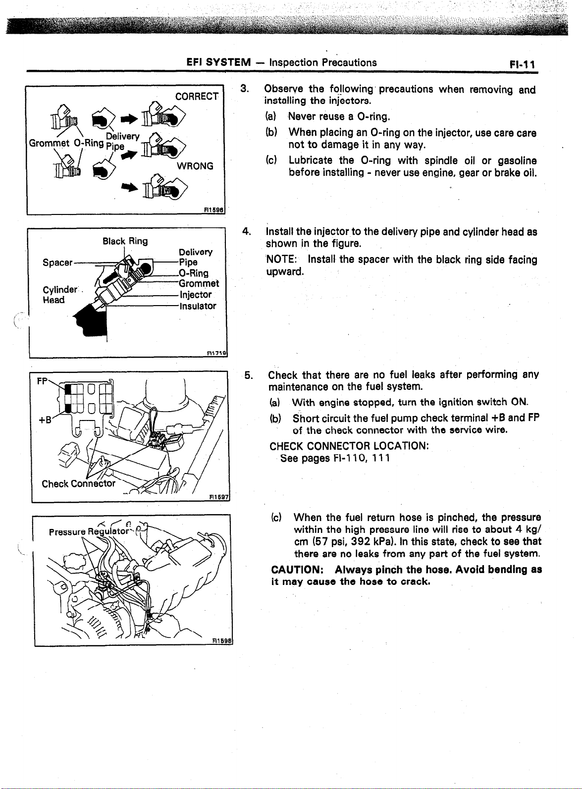
3.
Observe the fo!lowing’ precautions when removing and
installing the injectors.
(a) Never reuse a O-ring.
(b) When placing an O-ring on the injector, use care care
not to damage it in any way.
(c) Lubricate the O-ring with spindle oil or gasoline
before installing - never use engine, gear or brake oil.
4.
Install the injector to the delivery pipe and cylinder head as
shown in the figure.
‘NOTE: Install the spacer with the black ring side facing
upward.
FI-11
Check that there are no fuel leaks after performing any
5.
maintenance on the fuel system.
(a) With engine stopped, turn the ignition switch ON.
(b) Short circuit the fuel pump check terminal +B and FP
of the check connector with the service wire.
CHECK CONNECTOR LOCATION:
See pages FI-110, 111
(c) When the fuel return hose is pinched, the pressure
within the high pressure line will rise to about 4 kg/
cm (57 psi, 392 kPa). In this state, check to see that
there are no leaks from any part of the fuel system.
CAUTION: Always pinch the hose. Avoid bending as
it may cause the hose to crack.
Page 42

1-12
EFI SYSTEM
- Troubleshooting’
TROUBLESH~~TI~~G
. .
TROUBLESHOOTING HlhJTS
1. Engine troubles are usually not caused by the EFI system.
When troubleshooting, always first check the condition of
the other systems.
(a) Electronic source
0 Battery
0 Fusible links
0 Fuses
(b) Body ground
(cl Fuel supply
0 Fuel leakage
0 Fuel filter
0 Fuel pump
(d) Ignition system
0 Spark plug
0 High-tension cord
l
Distributor (7M-GE) or cam position sensor (7MGTE)
0 Igniter and ignition coil
(e) Air induction system
0 Vacuum leaks
(f) Emission control system
0 PCV system
0 EGR system (w/ EGR)
(g) Others
l
Ignition timing (ESA system)
0 Idle speed (ISC system)
2. The most frequent cause of problems is simply a bad dontact in wiring connectors. Always make sure that connec-
tions are secure.
When inspecting the connector, pay particular attention to
the following points:
(a) Check to see that the terminals are not bent.
(b) Check to see that the connector is pushed in com-
pletely and locked.
-r
FlO48
(c) Check to see that there is no signal change when the
connector is slightly tapped or wiggled.
3. Sufficiently troubleshoot for other causes before replacing the ECU. The ECU is of high quality and it is expensive.
Page 43

Digital Type
Analog Type
EFI SYSTEM - Troubleshdoting
. .
4. Use a volt/ohmmeter .with high impedance (10 k.RN
minimum) for troubleshooting of the electrical circuit.
(See pages FL34, 57)
FI-13
TROUBLESHOOTING PROCEDURES
SYMPTOM - DIFFICULT TO START OR NO START
(EbIJiiIf)l& WILL NO? CRANK OR CRANK$ SLOWLY)
CHECK ELECTRIC SOURCE
.-
OK
CHECK STARTING SYSTEM
BAD
BAD
w
1. Battery
(1) Connection
(2) Gravity - Drive belt - charging system
(3) Voltage
2. Fusible links
c
1. Ignition switch
2. Starter relay (MS)
3. Starter
4. Neutral start switch (A/T)
5. Wiring/Connection
Page 44

EFI SYSTEM - Troubleshootina
SYMPTOM - DIFFICULT TO START O-R NO START (CRANKS OK)
CHECK DIAGNOSIS SYSTEM
Check for output of diagnostic code.
(See page FI-26)
Normal code
DOES ENGINE’START WITH
ACCELERATORPEDALDEPRESSED?
NO
i
I
CHECK FOR VACUUM LEAKS IN AIR
INTAKE LINE
OK
I
CHECK IGNITION SPARK ’
7M-GE (See page IO-61
7M-GTE (See page IG-12)
OK
BAD
BAD
Diagnostic code(s) (See pages FI-30,‘31,32)
ISC system
0) ISC valve
(2) Wiring connection
I
1. Oil filler cap
2. Oil dipstick
3. Hose connections
4. PCV hose
5. (w/ EGR)
EGR system - EGR valve stays open
!
.
1. High-tension cords
2. Distributor (‘IM-GE) or cam position
sensor (7M-GTE)
3. Ignition coil
4. Igniter
I
t OK
CHECKSPARKPLUGS
Plug gap:
7M-GE Conventional Tipped Type
0.8 ‘mm (0.031 In.)
7M-GE
: : 1.1 mm (0.043~in.)
.7M-GTE
0.8 mm (0.031 In.)
NOTE: Check compression pressure and
valve clearance if necessary.
Platinum Tipped Type
OK
CONTINUED ON PAGE FI-15
NO
BAD
+
1. Spark plugs
2. Compression pressure
Limit: 9.0 kg/cm2 (128 psi, 883 kPa)
at 250 rpm
3. Valve clearance (Cold)
STD: IN 0.16 - 0.25 mm
(0.008 - 0.010 in.)
EX 0.20 - 0.30 mm
(0.008 - 0.012 in.1
1. Injector - shorted or leaking
2. Injector wiring between resistor and
ECU shorted
3. Cold start injector - Leakage
(See page Fl-80)
4. Cold start injector time switch
(See page Fl-115)
Page 45
EFI SYSTEM - Troubleshooting
FI-1 E
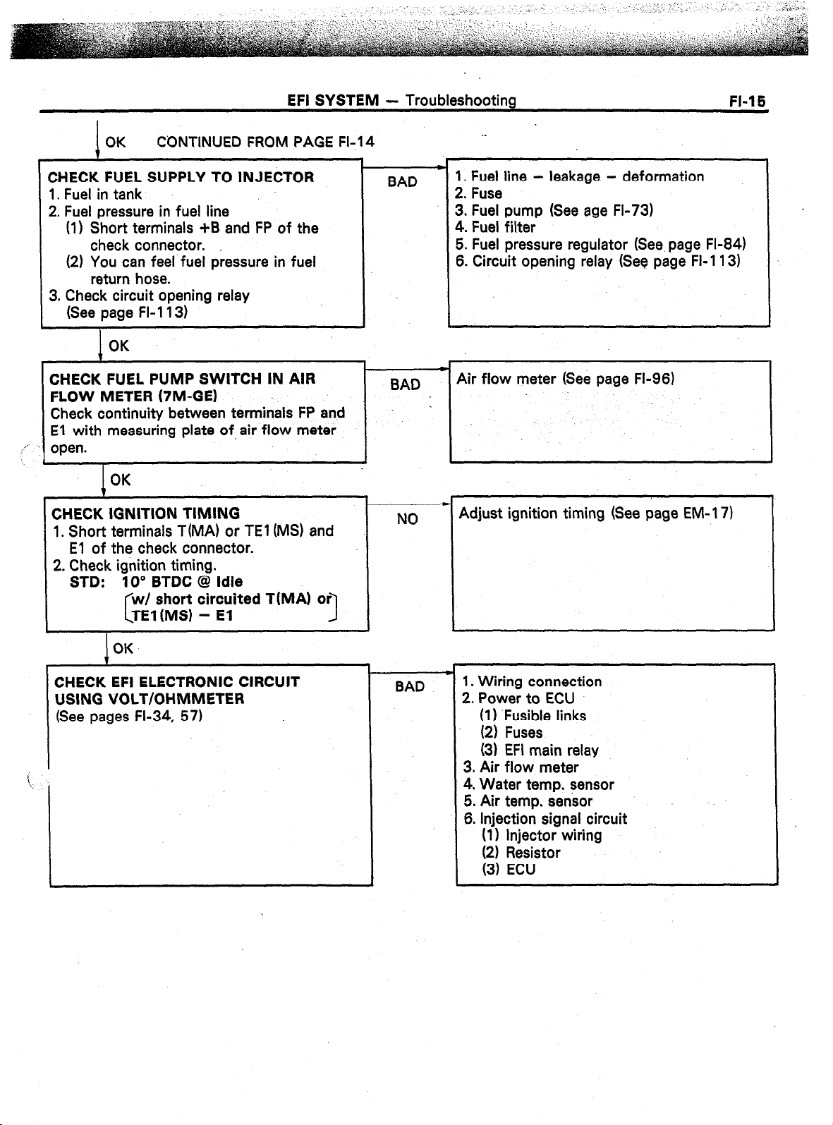
CONTINUED FROM PAGE FI-14
CHECK FUEL SUPPLY TO INJECTOR
1. Fuel in tank
2. Fuel pressure in fuel line
(1) Short terminals +B and FP of the
check connector.
(2) You can feel fuel pressure in fuel
return hose.
3. Check circuit opening relay
(See page FI-1 13)
OK
CHECK FUEL PUMP SWITCH IN AIR
FLOW METER (7M-GE)
Check continuity between terminals FP and
El with measuring plate of,air flow meter
,,’
open.
L
CHECK IGNITION TIMING
1. Short terminals T(MA) or TEl (MS) and
2. Check ignition timing.
I
OK
I
El of the check connector.
STD: 10’ BTDC @ Idle
short circuited TIMA) or
3
BAD
BAD
NO
._
1. Fuel line - leakage - deformation
2. Fuse
3. Fuel pump (See age FI-73)
4. Fuel filter
5. Fuel pressure regulator (See. page FI-84)
6. Circuit opening relay (See page FI-1 13)
c
Air flow meter (See page FL96)
Adjust ignition timing (See page EM-l 7)
I
OK
BAD
1. Wiring connection
2. Power to ECU
(1) .Fusible links
(2) Fuses
(3) EFI main relay
3. Air flow meter
4. Water temp. sensor
5. Air temp. sensor
6. Injection signal circuit
(1) Injector wiring
Page 46

l-16
EFI SYSTEM - Troubleshooting
CHECK DIAGNOSIS SYSTEM
Check for output of diagnostic code.
(See page Fl-26)
Normal code
CHECK FOR VACUUM LEAKS IN AIR
INTAKE LINE
OK
I
CHECK FUEL SUPPLY TO INJECTOR
‘*-- Fuel in tank
L. Fuel pressure in fuel line
(1) Short terminals +B and FP of the check
connector.
(2) You can feel fuel pressure in fuel
return hose.
3. Check circuit opening relay
(See page FI-113)
.
SYMPTOM -
Malfunction
code(s)
BAD
BAD
ENGINE OFTEN STALLS
* Diagnostic code(s) (See pages FI-30, 31, 32)
1. Oil filler cap
2. Oil level gauge
3. Hose connections
4. PCV hose
.
1. Fuel line - leakage - deformation
2. Fuse
3. Fuel.pump (See’ page FI-73)
4. Fuel filter
5. Fuel pressure regulator (See page FI-84)
6. Circuit opening relay (See page FI:1 13).
,
OK
CHECK AIR FILTER
I
OK
CHECK IDLE SPEED
STD: 7M-GE
7M-GE
7M-GTE
t
CHECK IGNITION TIMING ‘-
‘I. Short terminals TiMA) or TEl (MS) and
El of the check connector..
2. Check ignition timing.
STD: 10” BTDC @ Idling
OK
CHECK SPARK PLUGS
Plug gap:
7M-GE
0.8 mm (0.031 in.)
7M-GE
1.1 mm (0.043 in.)
7M-GTE
0.8 mm (0.031 in.)
NOTE: Check compression pressure and
-I------- :+ -nyrpCCpn,
wl TWC 700 rpm
w/o TWC 800 rpm
800 rpm
short circuited T(MA) or
Conventional Tipped Type
Platinum Tipped Type
1
-I-
BAD
BAD
NO
BAD -
Element - Clean or replace
w
ISC system
(I 1 Wiring connection
(21 ISC valve
(3) ECU
c
Adjust ignition timing. (See page EM-1 7)
1. Spark plugs
2. Compression pressure
Limit: 9.0 kg/cm2 (128 psi, 883
at 250 rpm
3. Valve clearance (Cold)
STD: IN 0.15 - 0.25 mm
(0.06 - 0.010 in.)
kPa)
Page 47

OK ‘. .CONTINUED FROM PAGE FI-I 6
CHECK COLD START INJECTOR
(See page FI-80)
OK
EFI SYSTEM - Troubleshooting
m
BAD
1. Cold start injector
2. Cold start injector time switch
(See page FL11 5)
FI-17
CHECK FUEL PRESSURE
(See page FI-74)
OK
CHECK INJECTORS
(See page FI-86)
OK
..I
’ CHECK EFI ELECTRONIC CIRCUIT
USING VOLT/OHMMETER
(See pages FI-34, 57)
I
BAD
BAD
BAD
p 1. Fuel pump (See page FL73)
2. Fuel filter
3. Fuel pressure regulator (See page FI-84)
c
Injection condition
1. Wiring connection
2. Power to ECU
(I) Fusible links
(2) Fuses
(3) EFI main relay
3. Air flow meter
4. Water temp. sensor
5. Air temp. sensor
6. Injection signal circuit
(I 1 Injector wiring
SYMPTOM - ENGINE SOMETIMES STALLS
CHECK DIAGNOSIS SYSTEM
I
Check for output of diagnostic code.
,dSee page FI-26)
‘I ,.
Normal code
I
CHECK AIR FLOW METER’
(See pages .Fl-96, 98)
I
OK
CHECK WIRING CONNECTORS AND
RELAYS
Check for a signal change when the connec- 3. Circuit opening relay (See page FI-113)
tor or relay is slightly tapped or wiggled.
1 BAD --
Air flow meter
2’ EFI main relay (See page FI 112)
I
Page 48

a
EFI SYSTEM - Troubleshooting
SYMPTOM - ROUGH IrIiLlNG AND/OR MISSING
iECK DIAGNOSIS SYSTEM
leek for output of diagnostic code.
ee page FI-26)
1
Normal code
HECK FOR VACUUM LEAKS IN’AIR
d-FAKE LINE
OK’
I
If* “K AIR FILTER
I
OK
CHECK IDLE SPEED
STD: 7M-GE
7M-GE
7M-GTE
OK
ELEMENT
w/ TWC 700 rpm
w/o TWC 800 rpm
800 rpm
Malfunction
code(s)
BAD
-c Diagnostic code(s) (See pages FI-30, 31, 32)
1, Oil filler cap
2. Oil level gauge
3. Hose connections
4. PCV hose
5. EGR system - EGR vaive stays open (EGR)
Element - Clean or replace
,
SC system
(1) Wiring connection
(2) ISC valve
(3) ECU
I
CHECK IGNITION TIMING
1, Short terminals T(MA) or TEI (MS) and
El of the check connector.
2. Check ignition timing.
STD: IO” BTDC @ Idling
w/ short circuited T(MA)
TEl(MS1 - El
I
i
‘.
I
CHECK SPARK PLUGS
Plug gap:
NOTE: Check compression pressure and
valve clearance if necessary.
OK
7
7M-GE
0.8 mm (0.031 in.)
7M-GE Platinum Tipped Type
1.1 mm (0,043 in.)
7M-GTE
0.8 mm (0.031 in.)
Converitional Tipped Type
OK CONTINUED ON PAGE FI-19
NO
BAD
F Adjust ignition timing. (See page EM-l 7)
1. Spark plugs
2. Compression pressure
Limit: 9.0 kg/cm2 (128 psi, 883
at 250 rpm
3. Valve clearance (Cold)
STD: IN 0.15 - 0.25 mm
(0.08 - 0.010 in.)
EX 0.20 - 0.30 mm
(0.008 - 0.012 in.)
kPa)
Page 49

EFI SYSTEM - Troubleshooting
FI-19
CONTINUED FROM PAGE Fl-18
CHECK COLD START INJECTOR
(See page FI-80)
CHECK FUEL PRES$URE
(See page FL74)
I
CHECK INJECTORS
(See page FI-86)
I
ZHECK EFI ELECTRONIC CIRCUIT
USING VOLT/OHMMETER
(See pages FL34, 57)
I
/OK
OK
I
1
._
t
*
BAD
BAD
1 c 4
8AD
BAD
1. Cold start injector
2. Cold start injector time switch
(See page FL11 5)
c 1. Fuel pump (See page FI-73)
2. Fuel filter
.3. Fuel pressure regulator (See page FI-84)
* Injection condition
c
1. Wiring connection
2. Power to ECU
\‘l’, F;t;e links
(3) EFI main relay
3. Air flow meter
4. Water temp. sensor
5. Air temp. sensor
6. Throttle position sensor
7. Injection signal circuit
(1) injector wiring
L
Page 50

.20
EFI SYSTEM - Troubleshooting __
SYMPTOM -
:HECK ACCELERA
OK
CHECK POWER STEERING !DLE+JP
SYSTEM
OK .
CHECK DIAGNOSIS SYSTEM
Check for output of diagnostic code.
(See page FI-26) ‘:.
_T I
Normal code
CHECK ISC SYSTEM
OK
‘:
j..l.
BAD
Malfunction
..
code!s)
I
HIGH ENGINE IDLE SPEED (NO DROP)
Linkage - Stuck
* Air valve
I
r
* Diagnostic code(s) (See pages FI-30, 31, 32)
.
BAD
(Air con Throttle posrtron sensor - ECU)
71
I
9
CHECK THROTTLE POSITION SENSOR
1
OK
CHECK FUEL PRESSURE
(See page FI-74)
OK
CHECK COLD START INJECTOR
~ .ee page FI-80)
CHECK INJECTORS (See page FI-86)
I
OK
I
CHECK EFI ELECTRONIC CIRCUIT USING
VOLT/OHMMETER
(See pages FI-34, 57)
t-x-
BAD
BAD
BAD -
Throttle body
7
w Fuel pressure regulator - High pressure
w Cold start injector - Leakage
Injectors - Leakage, Injection quality
1. Wiring connection
2. Power to ECU
(1) Fusible links
(2) Fuses
(3) EFI main relay
3. Air flow meter
4. Water temp. sensor
5. Air temp. sensor
6. Injection signal circuit
(1) Injector wiring
(2) Resistor
(3) ECU
Page 51

EFI SYSTEM - Troubleshooting
-.
FI-21
SYMPTOM - ENGINE BACKFtRES-Lean Fuel Mixture
CHECK DIAGNOSIS SYSTEM
Check for output of diagnostic code
(See page FI-26)
Normal code
CHECK FOR VACUUM LEAKS IN AIR
INTAKE LINE
1. Short terminals T(MA) or TEl (MS) and
Malfunction
--) Diagnostic code(s) (See pages FI-30, 31, 32)
.code 1s)
BAD -
NO
j
,
1. Oil filler cap
2. Oil dipstick
3. Hose connections
4. PCV hose
Adjust ignition timing. (See page EM-1 7)
1. Cold start injector
2. Cold start injector time switch
(See page FI-115)
CHECK FUEL PRESSURE
(See page FI-74)
I
I
’ “,HECK INJib
‘I- See page FI-86)’
. ., .l
OK
I
CHECK Eii ELECTRONIC ClR&lT
USING VOLT/OHMMETER
(See pages FI-34, 57)
I
BAD
1. Fuel pump (See page‘ FI-73)
2. Fuel filter
3. Fuel pressure regulator (See page Fl-84)
- Injectors - Clogged
BAD
4
BAD
1. Wiring connection
2. Power to ECU
(1) Fusible links
(2) Fuses
(3) EFI main relay
3. Air flow meter
4. Water temp. sensor
5. Air temp. sensor
6. Throttle position sensor
7. Injection signal circuit
(1) Injector wiring
Ii, zesstor
(4) Fuel cut signal
8. Oxygen sensor
Page 52

Ii-22
EFI SYSiiM - Troubleshooting
SYMPTOM - MUFFLER EXPLOSION (AFTER FIRE)
-Rich Fuel Mixture-Misfire
CHECK DIAGNOSIS SYSTEM
Check for output of diagnostic code
(See page FI-26)
Normal code
CHECK IGNITION TIMING
1. Short terminals TiMA) or TEl (MS) and
El of the check connector.
2. Check ignition timing.
STD: IO” BTDC @ Idling
w/ short circuited TfMA) or
TEl(MS) - El
C
OK
1
CHECK INJECTORS
OK
I
pm Diagnostic code(s) (See pages Fl-30, 31, 32)
Malfunction
code(s)
4
NO
I
BAD
c
Adjust ignition timing. (See page EM- 17)
1. Cold start injector
2. Cold start injector time switch
(See page FI- 115)
I-
BAD
injector - Leakage
I
I
CHECK SPARK PLUGS
Plug gap:
7M-GE
0.8 mm (0.031 in.)
7M-GE
1.1 mm (0.043 in.)
7M-GTE
0.8 mm (OiO31 in.)
NOTE: Check compression pressure and
valve clearance if necessary.
CHECK EFI ELECTRONIC CIRCUIT USING
VOLT/OHMMETER
(See pages Fl-34, 57)
Conventional .Tipped Type
Platinum Tipped Type
OK
NO
BAD -
1. Spark plugs
2. Compression pressure
Limit: 9.0 kg/cm2 (128 psi, 883
at 250 rpm
3. Valve clearance (Cold)
STD: IN 0.15 - 0.25 mm
(0.06 - 0.010 in.)
EX 0.20 - 0.30 mm
(0.006 - 0.012 in.)
1. Throttle position sensor
2. Injection signal circuit
(I) Injector wiring
(2) Resistor
(3) ECU
3. Oxygen sensor
i
kPa)
Page 53

EFI SYSTEM - Troubleshooting
FI-23
SYMPTOM
CHECK CLUTCH AND BRAKE
I
CHECK FOR VACUUM LEAKS IN AIR
INTAKE LINE
CHECK AIR FILTER ELEMENT
,,: -.
. . 1
CHECK DIAGNOSIS SYSTEM
Check for output of diagnostic code.
(See page FI-26)
I
CHECK IGNITION SPARK
I
OK
1
OK
I
OK
7
I
Normal code
1
7M-GE (See page IO-61
7M-GTE (See page 16-12)
I
OK
I
- ENGINE HESITATES AND/OR POOR ACCELERATION
.
BAD
1
BAD
I-
BAD
i ,
Malfunction
code
I--
I I
BAD
1. Clutch - Slips
2. Brakes - Drag
1. Oil filler cap
2. Oil level gauge
3. Hose connections :
4. PCV hose
5. EGR system - EGR valve stays open (EGR)
Element - Clean or replace
Diagnostic code(s) (See pages FI-30, 31, 32)
.
1. High-tension cords
2. Distributor (7M-GE) or cam position
sensor (7M-GTE)
3. Ignition coil
4. Igniter
4
I
1
J
CHECK IGNITION TIMING
1. Short terminals T(MA1 or TEl (MS) and
El of the check connector.
2. Check ignition timing.
STD: 10” BTDC @ Idling
‘i,
short circuited TiMA) or
I
OK
I
CHECK FUEL PRESSURE
(See page Fl-74)
OK
CHECK INJECTORS
(See page FI-86)
OK
CONTINUED ON PAGE FI-24
NO
I
Adjust. ignition timing. (See page EM- 17)
I
I
BAD
I
BAD
1. Fuel pump (See page Fl-73)
2. Fuel Filter
3. Fuel pressure regulator (See page Fl-84)
c Injection condition
1
Page 54

. .
FI-24
1
OK
CONTINUED FROM PAGE FL23
EFI SYSTEM - Troubleshooting
,)
CHECK SPARK PLUGS
Plug gap:
7M-GE
03 mm (0.031 ,in.)
Conventional Tipped Type
.~
7M-GE Platinum Tipped Type
1.1 mm (0.043 in.)
7M-GTE
0.8 mm (0.031 in.)
NOTE: Check compression prossure and
valve clearance if necessary.
. r
1
.
;HECK EFI ELECTRONIC’CIRCUIT
-;-;ilNG VOLT/OHMMETER
_
(See-pages FI-34;‘57) Y
BAD
BAD
L
1. Spark plugs
2. Compression pressure
Limit: 9.0 kg/cm2 (128 psi, 883
at 250 rpm
3. Valve clearance (Cold)
STD: IN 0.15 - 0.25 m&
(0.06 -‘.O.OlO in.)
EX 0.20 - 0.30 mti
(0.008 - 0.012 in.1
.
c
1. Wiring connection
2. Power to ECU
(I) Fusible links
(2) Fuses
(3) EFI main relay
3. Air flow meter.
4. Water temp. sensor
5. Air temp. sensor
6. Throttle position sensor
7. Injection signal circuit
(I) Injector wiring
(2) Resistor
(3) ECU
kPa)
’
Page 55

EFI SYSTEM
. .
- Diagnosis System
FL25
DIAGNOSIS SYSTEM
__ --
(MA)
The ECU contains a built-in self-diagnosis system by which
troubles with the engine signal network are detected and a
“CHECK ENGINE” warning light on the instrument panel
flashes,
By analyzing various signals as shown in the later table (See
pages Fl-30, 31) the Electronic Control Unit (ECU) detects
system malfunctions which are related to the various operating
parameter sensors or to the actuator. The ECU stores the
failure until the diagnosis system is cleared by removing the EFI
fuse with the ignition switch off.
A “CHECK ENGINE” warning light on the instrument panel
informs the driver that a malfunction has been detected.
The light goes out automatically when the malfunction has
been cleared.
The diagnostic code can be read by the number of the blinks of
the “CHECK ENGINE” warning light when T and El are short-
circuit.
(MS)
The ECU contains a built-in self-diagnosis system by which
troubles with the engine signal network are detected and a
“CHECK ENGINE” warning light on the instrument panel
flashes.
By analyzing various signals as shown in the later table (See
page FI-32) the Electronic Control Unit (ECU) detects system
malfunctions which are related to the various operating
parameter sensors or to the actuator. The ECU stores the
failure until the diagnosis system is cleared by removing the EFI
fuse with the ignition switch off.
In the ECU, a test mode function has been added to the functions of the self-diagnosis system of the previous diagnosis
mode (normal mode) for the purpose of detecting malfunctions
such as poor contact which are difficult to detect in the normal
mode. This function fills up the self-diagnosis system. The test
mode can be implemented by the technician to follow the procedures of appropriate check terminal connection and operation described in later (See page FI-28).
In the normal mode, the self-diagnosis system monitors 14
items, indicated by the codes except for code No. 51 as shown
in FI-32. A “CHECK ENGINE” warning light on the instrument
panel informs the driver that a malfunction has been detected.
The light goes out automatically when the malfunction has
been cleared.
The diagnostic code can be read by the number of the blinks of
the “CHECK ENGINE” warning light when TEl and El are
short-circuited.
Page 56

FI-26
EFI SYSTEM -
-.
In the test mode, seven items, indicated by code
24, 41, 42, 43, and 5 1, as shown in FI-32 are m
malfunction is detected in any one of the systems
code Nos. 13, 22, 24, and 41 the ECU lights the “CHECK
ENGINE” warning light to warm the technician that the malfunction has been detected. In this case, TE2 and El terminals
on the check connector should be connected as shown later
(See page FI-28)
In the test mode, for all seven conditions shown above in code
Nos. 13 function is stored in the ECU memory while the ignition switch
remains on. Also, when a malfunction occurs for-the four conditions from code Nos. 13 - 41, the “CHECK ENGINE” warning
light remains on. However, once the ignition switch is turned to
OFF, the ECU erases all of the malfunctions in the memory. The
diagnostic mode (normal or test) and the output of the “CHECK
ENGINE” warning light can be selected by the TEl , TE2 and El
terminal connections on the check connector, as shown in the
later.
Diagnosis System
51, even if the malfunction is corrected, the mal-
i
“CHECK ENGINE” Warning Light
“CHECK ENGINE” WARNING LIGHT CHECK
1. The “CHECK ENGINE” warning light will come on when
the ignitiorqw:@ch is placed at ON and the engine is not
running.
2. When the engine is started, the “CHECK ENGINE” warning
light should go out.
If the light remains on, the diagnosis system has detected
a malfunction or abnormality in the system.
-y.
OUTPUT OF DIAGNOSIS CODES
(MA)
To obtain an output of diagnostic codes, proceed as follows:
1. Initial conditions
(a)’ Battery voltage about 11 volts
(b) Throttle valve fully closed (throttle position sensor
IDL points closed)
(cl Transmission in neutral position
(d) Accessory switches OFF
,’
Turn the ignition switch to ON. Do not start the engine.
2.
Page 57

Osc db-5 hus
4J
EFI SYSTEM
-.
-7.
- Diagnosis System
w
FI-27
3. Using a service- wire, short terminals T(MA) or TEr(MS)
and El of the check connector.
CHECK CONNECTOR LOCATION:
See pages FI-110, 111
4. Read the diagnosis code as indicated by the number of
flashes of the “CHECK ENGINE” warning light.
“CHECK ENGINE” Warning Light
Code No. 13 Code No. 32
(Seconds)
FlO29
Diagnosis. code (See pages FI-30, 31, 32)
(a) Normal System Operation
l
The light will alternately blink on and off for 0.25
second intervals.
.)
(b) Malfunction Code Indication i
l
The light will blink the number of times equal to
the malfunction code indication with pauses asfollows:
1.
Between the first digit and se&d digit, 1.5
seconds.
2.
Between code and code, 2.5 se$onds.
3. Before repeating all malfunction codes, 4.5
seconds.
0 The diagnostic code series will be repeated as long
as the “CHECK ENGINE” connector terminals
T(TE1) and El are shorted.
NOTE: In event of a number of trouble codes, indication
will begin from the small value and continue to the larger
in
order.
After the diagnosis check, remove the service wire.
Page 58

EFI SYSTEM;
Diagnosis System
I
Fl281
S)
Test mode
To obtain an output of diagnostic codes, proceed as follows:
1. Initial conditions
Battery voltage about 1 1 volts
(a)
(b) Throttle valve fully closed (throttle position sensor
(c) Transmission in neutral position
(d) Accessory switches OFF
2. Using a service wire, short terminals TE2 and El of the
check connector.
*-heengine and run the vehicle at a speed of IO km/h
(6 mph) or higher. __--
------) -.
IDL points closed)
_ ___ _.--.--.
-----.-q
/---’
i
j
\
I
4. Simulate the conditions of the malfunction described by
the user.
Using a service wire, short terminals TEl and .El of the
5.
check connector.
NOTE:
l
The test mode will not start if terminals TE2 and El are connected after the ignition switch is turned on, or terminals TE2
and El are connected after terminals TEI and El are con-
nected.
0 The starter signal and vehicle speed signal will be diagnosed
by the ECU as malfunctions, and codes No. 42, and 43 will
be output, if the operation in 3. above is not performed.
Read the diagnosis code as indicated by the number of
6.
flashes of the “CHECK ENGINE” warning light.
(See page FI-27)
7. After the diagnosis check, remove the service wires.
l
Page 59

MS EFI 15iA
LHD
EFI 15A
EFI SYSTEM
CANCELLING OUT DIAGNOSTIC CODE
1.
2.
- Diagnosis System
FI-29
After repair of the trouble area, the diagnostic code
retained in memory by the ECU must be cancelled out by
removing the EFI fuse 15A for 30 seconds or more,
depending on ambient temperature (the lower the temperature, the longer the fuse must be left out) with the
ignition switch off.
NOTE:
l
Cancellation can also be done by removing the battery”
negative (-1 terminal, but in this case other memory
systems (clock etc.) will also be cancelled out.
l
If the diagnostic code is not cancelled out, it will be
retained by the ECU and appear along with a new code
in event of future trouble.
l
If it is necessary to work on engine components requiring removal of the battery terminal, a check must first
be made to see if a diagnostic code has been recorded.
After cancellation, road test the vehicle to check that a
“normal” code is now read on the “CHECK ENGINE”
warning light.
If the same diagnostic code is still indicated, it means that
the trouble area has not been repaired thoroughly.
EFI 15A
R16C
FI26:
DIAGNOSIS INDICATION
(I) When 2 or more codes are indicated, the lowest number
(code) will appear first.
However, no other code will appear along with code No.
11.
(2) All detected diagnostic codes, except 51 and 53, will be
retained in memory by the ECU from the time of detection
until cancelled out.
(3) Once the malfunction is cleared, the “CHECK ENGINE”
warning light on the instrument panel will go out but the
diagnostic code(s) remain stored in ECU memory (except
for codes 51 and 53).
Page 60

I-30
d
.EFl SYSTE.M -
DIAGNOSTIC CODES (MA)
Diagnosis System
Code
; No.
I
- nnrulno4 Norma’
11
24
Number of
Che;;;;gine
nn n
i-
I
ECU (+B) fl n
gnition Signal
I!
Fll608
(
3xygen Sensor
!
signal
FIl609
1
Water Temp.
Sensor Signal
,-
Fll81t
Intake Air Tern
1
Fll81
Fl161
Fl18
FIZE
System
Sensor Signal
Air-flow
Meter Signal
(‘IM-GE)
Air Flow
Meter Signal
(7M-GTE)
HAC Sensor
Signal
Turbocharger
Pressure
n
Sensor Signal
SHl,d
I
Diagnosis
This appears when none of
the other codes area identified.
Momentary interruption in
power supply to ECU.
Jo “NE” or “G” signal to
ICU within 2 seconds after
engine has been cranked.
Uo “NE” signal to ECU when
sngine Sp88d is above
1,000 rpm.
No “IGF” signal to ECU
8 times in succession.
i-
E
Ietectinn of oxygen sensor
t
jeterioration.
C
i
Open or short circuit in wate
temp. sensor signal.
Open or short circuit in intake
P.
air temp. sensor signal.
I7M-GE)
Open circuit in VC signal or
short circuit between VS and
E2 when idle contacts are
c tosed.
(7M-GTE)
Open or Short circuit in air
flow meter signal.
(‘IM-GE)
Open circuit in E2 or short
circuit between VC and VS.
(‘IM-GTE)
Open or short circuit in HAC
sensor signal
‘3
Turbocharger pressure is
abnormal.
Open or short circuit in
throttle position sensor signal.
Trouble area
0
Ignition switch circuit
Ignition switch T
0
Main relay circuit
0
1 Main relay
l
I
1 ECU
1 Distributor circuit
r Distributor
) Starter signal circuit
b ECU
) Distributor circuit
B Distributor
B ECU
B Ignition and ignition coil
circuit
8 Igniter and ignition coil
0 ECU
0 Oxygen sensor circuit
l
Oxygen sensor
0 ECU
0 Water temp. sensor
@muit
‘8 Water temp. sensor
l
ECU
0 Intake air temp. sensor
circuit
8 Intake air temp. sensor
. ECU
0 Air flow meter circuit
0 Air flow meter
0 ECU
0 Air flow meter Circuit
0 Air flow meter
0 ECU
0 HAC sensor circuit
l
HAC sensor
l
ECU
0 Turbocharger
8 Air flow meter
0 Intercooler system
0 ECU
,
0 Throttle position s8nsC
circuit
0 Throttle position sensor
0 ECU
I
See
page
FI-41
IG-3
IG-3
!I-5 1
l-l 2
FI-4’
Fl-48
FI-44
FI-4‘
FI-51
)r
, FI-4
Page 61

EFI SYSTEM
__
DIAGNOSTIC CODES (MA) (Cont’d)
- Diagnosis System
FI-31
:odc
No.
42
52
Number of
Check engine
System
Diagnosis
blinks
No “SPD” signal for 5
seconds when engine speed
Vehicle Speed
Sensor Signal
is between 2,500 rpm and
4,500 rpm and coolant temp.
is below 80°C (176’F) except
FI161
when racing the engine.
No “STA” signal to ECU until
Starter Signal
FHBl
Knock Sensor
Signal
Fl181
Knock Control
signal in ECU
FIlei
engine speed reaches 800
rpm with vehicle not moving.
Open or short circuit in knock
sensor signal.
Knock control in ECU faulty.
No “IDL” signal, “NSW”
Switch Signal
signal or “A/C” signal to
ECU, with check terminals
El and T shorted.
‘1 WI TWC vehicles only
‘2 7M-GTE only
“3 Abnormalities in the air flow meter may also be detected.
Trouble area
l
Vehicle speed sensor
circuit
l
Vehicle speed sensor
. ECU ’
l
Ignition switch circuit
l
Ignition switch
l
ECU
l
Knock sensor circuit
l
Knock sensor
l
ECU
I
. ECU
l
A/C switch circuit
l
A/C switch
l
A/C am&fire
l
Neutral start switch
‘“q
circuit ’
l
Neutral start switch
0 Throttle position sensor
circuit
l
Throttle position sensor
l
ECU
See
page
FL50
Number of
Check engine
blinks
m Normal
11
nn
12
n nn
-
13
nnnn,
-
14
-LJUlJUL 1 Ignition Signal 1 *
fl1604
FI1605
FHBOB
Fl1807
System
ECU (B)
RPM Signal
RPM Signal
DIAGNOSTIC CODES (MS)
Diagnosis
This appears when none of
the other codes are identified.
l
Ignition switch circuit
l
Momentary interruption in
power supply to ECU.
No “NE” or “G” signal to
ECU within 2 seconds after
engine has been cranked.
No “NE” signal to ECU when
engine speed is above
1,000 rpm.
No. “IGF” signal to ECU
6 - 8 times in succession.
Ignition switch
l
Main relay circuit
l
Main relay
l
ECU
l
Distributor circuit
0 Distributor
l
Starter signal circuit
. ECU
l
Distributor circuit
l
Distributor
. ECU
l
Igniter and ignition coil
circuit
0 Igniter and ignition coil
. ECU
Trouble area
.t
See
page
FI-62
IG-3
IG-3
Fl-70
Page 62

FI-32
I
EFI SYSTEM -
DIAGNOSTIC CODES (MS) (Cont’d)
Diagnosis System
‘.
1
ode
‘( <;
r
32
41
Number of
Check engine
System
Diagnosis
Trouble area
blinks
0 Water temp. sensor
. .
clrcult m n
0 Water temp. sensor
0 ECU _
0 Intake air temp. sensor
circuit
0 intake air temp. sensor
. ECU
0 Air flow meter circuit
:
JUMJJJL
FllBlO
fll611
Intake Air Temp.
Open or short circuit in intake
Sensor Signal air temp. sensor signal.
Open circuit in VC signal or
JJJJ n f
F11612
closed.
.
i Air flow meter circuit
Fl1613
Fl1614
I
I
Open or short circuit in
throttle position sensor signal.
I
0 Throttle position sensor
circuit
0 Throttle position sensor
. ECU
!
No “SPD” signal for 5
seconds when engine speed
0 Vehicle speed sensor
See
paw
FI-68
FI-67
4-65
FI-6!
FM
i
? -.
.I
.^
42
43
nnnruvl
is below 80°C (176°F) except
fl16151
I
when racing the engine.
No “STA” sianal to ECU until
0 Ignition switch circuit
m Starter Signal /~~n~i,‘,pee~;~ct-;~~~ng : ;;;on switch
Fl1616
0 Knock sensor
52
53
JjJJMJjn
I
w6,9 Kn$c~i~“,“,‘;“’ Knock control in ECU faulty.
Eyn$ Sensor ~~n~op:~~ circuit in knock : :gk sensor
F11616
l
0 A/C compressor relay
A/C Com-
pressor
Relay Signal
Z
f12611
Open or short circuit in
A/C compressor relay signal.
a A/C compressor relay
. ECU
0 A/C switch circuit
0 A/C switch
0 A/C amplifire
No “IDL” signal, “NSW”
51
l
0 Neutral start switch
0 Throttle position sensor
0 Throttle position Sensor
. ECU
F11617
FM
circuit
ECU
circuit
Neutral start switch
circuit
circuit
Page 63

EFI SYSTEM
- Diagnosis System
FI-33
INSPECTION OF DIAGNOSIS .ClRCUlT
._
Fuse IGN
“CHECK ENGINE”
Fl291
1.
Dose “CHECK ENGINE” warning light come
on when ignition switch is at ON?
I
Does “CHECK ENGINE” warning light come
on when ECU terminal W is grounded to the
body?
+NO
Check bulb, fuse and wiring between ECU and
ignition switch.
Does “CHECK ENGINE” warning light go off
when the engine is started?
NO
Check wiring between ECU and
“CHECK ENGINE” warning light.
1 OK
Is there diagnostic code output when check
connector terminals T(MA) or TEl (MS) and
El are short circuited?
I
YES
Does “CHECK ENGINE” warning light go out NO
after repair according to malfunction code?
&
YES System Normal
l-l
Check wiring between
YES ECU terminal El and body
- ground.
__c ECU
OK
Try another
+ SAD
Repair or replace
YES
. System Normal
t
Check wiring between ECU terminal T and check
NO connector terminal T(MA) or TEl (MS), and ECU
I
* terminal El and check connector terminal El.
I
) Further repair required.
I
System OK
Cancel out diagnostic code.
Page 64

-34
EFI SYSTEM - Troubleshooting with Volt/dhmmeter (MA)
. .
TROUBLESHOOTING WITH
VOLT/OHMMETER (MA)
OTE: The following troubleshooting prosdures are designed for inspection of each separte system, and therefore the actual procedure
lay vary somewhat. However, troubleshooting
hould be performed refering to the inspection
lethods described in this manual.
Jefore beginning inspection, it is best to first make
3 simple check of the fuses, fusible links and the
:ondition of the connectors.
LOCATION OF FUSES AND FUSIBLE LINKS
1 Relay Block (RHD)
No.
r
I
The following troubleshooting procedures are
based on the supposition that the trouble lies in
either a short or open circuit in a component out-
side the computer or a short circuit within the
computer.
If engine trouble occurs even though proper
operating voltage is detected in the computer con-
nectar, then it can be assumed that the ECU is
faulty and should be replaced.
No. 1 Relay Block (LHD)
61 I
Fuse IGN’
Fusible Link
ALT
(7M-GE) 1.259 \
(7M-GTE) 1 OCjA
No. 2
Relay Block
Fusible Link
AM2 30A
Fuse IdN 7.5A
EFI Main Relay
Fuse EFI 15A
Page 65

EFI SYSTEM - Troubleshooting with Volt/Ohmmeter (MA)
*For
cruise
control
. .
EFI SYSTEM CHECK PROCEDURE
NOTE:
l
Perform all voltage measurements with the connectors
connected.
0 Verify that the battery voltage is 11V or above when
the ignition switch is at “ON”.
Using a voltmeter with high-impedance (IO kQ/V
minimum), measure the voltage at each terminal of the
wiring connectors.
FI-35
I )
ECU
+B
Terminals of ECU (7M-GE)
Symbol ) Terminal Name
E01 POWER GROUND
E02 POWER GROUND
No. 10 INJECTOR (No. 1 and 4)
No. 20
STA STARTER SWITCH
No. 30 INJECTOR (No. 3 and 5)
STJ
NSW NEUTRAL START SWITCH (A/T)
ISC 1 ISC MOTOR NO. 1 COIL ox OXYGEN SENSOR vc
ISC 3
ISC 2
ISC 4 ISC MOTOR NO. 4 COIL Ll ECT COMPUTER +B EFI MAIN RELAY
ECU Terminals
INJECTOR (No. 2 and 6)
COLD START INJECTOR
El COMPUTER GROUND
N/C *CLUTCH SWITCH (M/T)
ISC MOTOR NO. 3 COIL E2 SENSOR GROUND
ISC MOTOR NO. 2 COIL VSV 1 VSV (AIR CONTROL)
GQ
DISTRIBUTOR VSVP VSV (FPU) IG S/W IGNITION SWITCH
VF CHECK CONNECTOR
Gl DISTRIBUTOR
1 Symbol) Terminal Name
T CHECK CONNECTOR
G2 DISTRIBUTOR
VTA THROTTLE POSITION SENSOR
NE DISTRIBUTOR
IDL THROTTLE POSITION SENSOR
IGT IGNITER
IGF IGNITER
THW WATER TEMP. SENSOR
KNK KNOCK SENSOR LP HEADLIGHT RELAY
1 L2 ECT COMPUTER
1 M-REL EFI MAIN RELAY (COIL)
Symbol
L3 ECT COMPUTER
EGR
A/C A/C MAGNET SWITCH
SPD SPEEDOMETER
W WARNING LIGHT
FPR FUEL PUMP RELAY
DFG
THA
ECT
vs AIR FLOW METER
BATT BATTERY
+Bl
Terminal Name
vsv
(EGR)
DEFOGGER RELAY
AIR TEMP. SENSOR
ECT COMPUTER
THROTTLE POSITION SENSOR
AIR FLOW METER
EFI MAIN RELAY
F10574
Page 66

FI-36 EFI SYSTEM -
Troubleshooting with VoltjOhmmeter (MA)
Terminals of ECU. (7M;GTE)
Symbol Terminal Name Symbol Terminal Name Symbol Terminal Name
EOI
E02 POWER GROUND VTA
No, 10 INJECTOR (No. 1 and 4)
No. 20 INJECTOR (No. 2 and 6) IDL
STA STARTER SWITCH IGT IGNITER OIL OIL PRESSURE SWITCH
No. 30 INJECTOR (No. 3 and 5) IGdA IGNITER THA AIR TEMP. SENSOR
STJ
rEl COMPUTER GROUND KNKl KNOCK SENSOR
NSW
IGdB
ISC 1
r
ISC 3 ISC MOTOR NO. 3 COIL
ISC 2 ISC MOTOR NO. 2 COIL Ll ECT COMPUTER IG S/W IGNITION SWITCH
ISC 4 ISC MOTOR NO. 4 COIL
ECU Terminals
POWER GROUND G2 CAM POSITION SENSOR A/C A/C MAGNETIC SWITCH
N/C
THROTTLE POSITION SENSOR
NE CAM POSITION SENSOR
THROTTLE POSITION SENSOR
COLD START INJECTOR
NEUTRAL START SWITCH (A/T)
IGF
THW WATER TEMP. S
IGNITER ECT ECT COMPUTER
ENSOR 1 FC 1 CIRCUITOPENING RELAY
‘CLUTCH SWITCH (M/T) KNK2 KNOCK SENSOR 1 vc )
SPD SPEEDOMETER
W
WARNING LIGHT
FPR FUEL PUMP RELAY
t HAC 1 tl
LTITUDE COMPENSATION
, .xNSOR
THROTTLE
AIR
FLOW I
IGNITER ox OXYGEN SENSOR KS AIR FLOW METER
ISC MOTOR NO. 1 COIL E2 SENSOR GROUND BATT BATTERY
vsv VSV (FPU)
+B EFI MAIN RELAY
HT OXYGEN SENSOR +Bl EFI MAIN RELAY
GO
CAM POSITION SENSOR L2 ECT COMPUTER
VF CHECK CONNECTOR
CAM POSITION SENSOR L3 ECT COMPUTER LP HEADLIGHT RELAY
Gl
CHECK CONNECTOR
T
M-REL
EFI MAIN RELAY (COIL)
EGR VSV (EGR)
TIL
TURBO INDICATOR
DFG DEFOGGER RELAY
I
+
*For cruise control
E2 Ll L2 L3 A/C W OIL ECT FC KS +B +Bl
F10574 Fll 99:
Page 67
EFI SYSTEM
- Troubleshooting with’ Volt/Ohmmeter (MA)
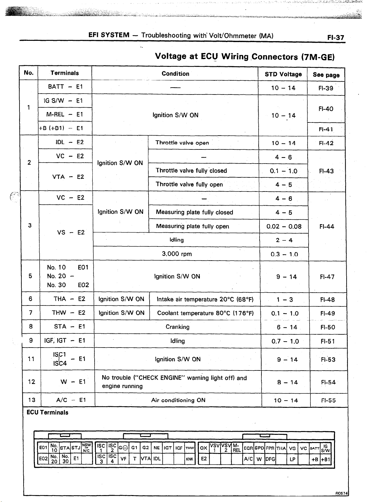
Voltage at EClJ Wiring .Connectors (TIM-GE)
FI-37
IO.
Terminals
BATT - El
Condition STD Voltage
10 - 14 FI-39
See page
IG S/W - El
1 FI-40
M-REL - El
Ignition S/W ON 10 - 14
+B (+Bl) - El FI-41
IDL - E2 Throttle valve open 10 - 14 FI-42
vc
- E2
-
4-6
2 Ignition S/W ON -
Throttle valve fully ‘closed
0.1
- 1.0
FI-43
VTA - E2
Throttle valve fully open 4-5
VC - E2 4-6
Ignition S/W ON
Measuring plate fully closed 4-5
3 Measuring plate fully open 0.02 - 0.08 FI-44
VS - E2
Idling 2-4
3,000 rpm 0.3 - 1.0
No. 10 EOI
5 No. 20 - Ignition S/W ON 9 - 14 FI-47
No. 30
6
THA - E2 Ignition S/W ON Intake air temperature 20°C (68°F) 1 -3 FI-48
7 THW - E2
8 STA - El
9 IGF, IGT - El
11
ISCI
I&4
12 W - El
13 A/C - El
E02
Ignition S/W ON Coolant temperature 80°C II 76’F)
Cranking
Idling
0.1 - 1 .O
6 - 14
0.7 - 1.0
FI-49
FI-50
FI-5 1
- El Ignition S/W ON 9-14 Fl-53
No trouble (“CHECK ENGINE” warning light off) and
engine running
Air conditioning ON IO - 14
8 - 14 FI-54
FI-55
ECU Terminals
4
N:y Is’ Is’
GO Gl G2 NE IGT IGF
THW
OX
“s, “;“riL
EGR SPD FPR THA VS VC BATT IG
‘~,~] E2
/UC W:G up +S :,:I
F1057
Page 68

EFI SYSTEM
- Troubleshooting with Volt/Ohmmeter (MA)
. .
Voltage at ECU Wiring Connectors (7M-GTE)
No.
Terminals
BATT - El 10 - 14
IG S/W - El
1
M-REL - El Ignition S/W ON 10 - 14
+B (+Bl) - El
IDL - E2 Throttle valve open 10 - 14 FI-42
VC - E2
2 . Ignition S/W ON
VTA - E2
i
KS - Body
gnMid
4
vc - Body
groulld
No. 10
EOl
5 No. 20 -
No. 30 E02
Condition STD Voltage Sea page
FI-39
FI-40
*
FI-41
4-6.
Throttle valve fully closed 0.1 - 1.0 FI-43
Throttle valve fully open 4-5
Ignition S/W ON 4-6
FI-45
Cranking or running 2-4
Ignition S/W ON 4-6
Fl-46.
Ignition S;W CN 9 - 14 Fl-47
6
7
8
THA - E2 Ignition S/W ON Intake air temperature 20°C (68°F) 1 -3 FI-48
THW - E2 Ignition S/W ON Coolant temperature 80°C (176°F) 0.1 - 1 .O FI-49
STA - El Cranking 6-14 FI-50
9 IGF, IGT - El Idling
10 IGdA, IGdB -
11
I Cl
7
ISC4
12
13 A/C
El Idling 1-3 FI-52
- El Ignition S/W ON
W - El
- El
No trouble (“CHECK ENGINE” warning light off) and
engine running
Air conditioning ON 10 - 14
540 mmHg (21.26 in.Hg. 72.0 kPa) Approx. 2.8
14 HAC - E2
Ignition S/W ON
750 mmHg (29.53 in.Hg, 100.0 kPa) Approx. 3.6
ECU
Terminals
U
I
‘yc ‘;c GQ Gl G2 NE IGT IGF ~Hln, OX “;’ HT r;,
‘;’ ‘sd: VF T VTA IDL
1 I
WA
““1” K;K E2 Ll L2 L3 NC W OIL ECT FC KS +B +Bl
-
EGR
SPD FPR THA
I
HAC
VC ‘JAn&
0.7 - 1.0 FI-5 1
9 - 14 FI-53
8 - 14 FI-54
FI-55
FI-56
1
m\
0
DF
TIL LP
Page 69

EFI SYSTEM
- Troubleshooting with~Volt/Ohmmeter (MA)
FI-39
lo.
1
Terminals Trouble
I
BAT1 -El No voltage
IO S/W - El No voltage lgnitlon switch ON
1 M-REL - El 1 No voltage 1
1 +B (+Bl) - El1 No voltage
Fusible
Link
Battery
I
Fusible Link
. BATT - El
0
ConcJition
ignition switch ON I IO-14v
lgnitlon switch ON lo-14v
ECU
+Bl
+B
M-REL
IG S/W
El
STD Voltage
IO- l4V
10 - 14 v
Voltmeter
V+
J
ECU
I,
ECU
n
BATT
BATT I!
@ There is no voltage between ECU terminals BATT and El.
1
Check that there is voltage between ECU terminal BATT and
0
body ground.
NO OK
Check wiring between ECU terminal El and body
0
OK
ground.
I
BAD
H
Replace.
I I
Repair or replace.
I ’ I
I
I
I
Check wiring between ECU terminal
and battery.
I
I I I J
I
I
I
Page 70

FI-40
EFI SYSTEM - Troubleshooting with Volt/Ohmmeter (MA)
. IG S/W - El --
There is no voltage between ECU terminals IG S/W and El.
0
(IG S/W ON1
1
Voltmeter
1
Check that there is voltage between ECU terminal IG S/W and
CD
body ground. (IG S/W ON)
NO OK
Check wiring between ECU terminal El and body
ground.
’ OK
Try another ECU.
Check fuse, fusible links and BAD
. M-REL - El
There is no voltage between ECU terminals M-REL and El.
0
(IG S/W ON)
1
Check that there is voltage between ECU terminal M-REL and
0
body ground. (IG S/W ON)
Repair or replace.
Voltmeter
Ed ., +
NO OK
Check wiring between ECU terminal El and body
ground.
OK
Try another ECU.
Check EFI main relay and wiring
harness.
I
Try another ECU.
I
I
I
BAD
c Replace.
Replace or repair.
4
Page 71

EFI SYSTEM
- Troubleshooting with Volt/Ohmmeter (MA)
. +B (+Bl) - El
There is no voltage between ECU terminals +B
0
(IO SAN ON)
I
0 Check that there is voltage between ECU terminal +B (+Bl 1
and body ground. (IO S/w ON)
I
I
NO OK
Check wiring between ECU terminal El and body ground.
FI-41
I
OK
Try another ECU.
Check fuse, fusible links and wiring BAD
harness.
I
I
I I I
I
OK
1
Check EFI main relay.
(See page FI-1 12)
OK
Refer to M-REL - El trouble
section.
I
I
1 I I
H
I I
BAD
I
BAD
Replace or repair.
Repair or replace.
* Replace.
I
I
1
Page 72

;I-42
EFI SYSTEM - Troubleshooting with Volt/Ohmmeter (MA)
NO,
2 }-I No voltage / s$t;;N -
Terminals
IDL - E2
VTA - E2
I
I
Throttle Position Sensor
Trouble
I I
I I
I
l
IDL - E2
Condition ..
Throttle valve open
Throttle valve fully closed
Throttle valve fully c
STD Voltage
10 - 14 v
o.‘: I;,; v
4-5v
I
Ei
IDL
VTA
VC
El
I
Voltmeter
R102,
FlO31
There is no voltage between ECU terminals IDL and E2.
0
(IO S/W ON) (Throttle valve open)
c
c
I
Check that there is voltage between ECU terminal +B (+Bl)
0
and body ground. (IO S/W ON)
, 1
OK ’
1
1 1 Check wiring between ECU terminal El and body ground.1
t
Refer to No. 1.
(See page FI-41)
BAD
7
- Replace or repair.
I
,
I@ Check throttle position sensor.
OK
BAD
I
1
1
1
OK
Check wiring between ECU and
throttle position sensor.
b
h
1
BAD
.
1
Page 73

EFI SYSTEM
- Troubleshooting with Volt/Ohmmeter (MA)
l
(r:
VC - E2
There is no voltage between ECU terminals VC and E2.
0
(IO
S/W ON)
FI-43
Voltmeter
v:
El
c
ECU A VTA
I
cc
1
Check that there is voltage between ECU terminal +6 (+El) and
body ground. (IO S/W ON)
OK
Check throttle position sensor,
CD
(See page FI-102)
BAD
I
Repair or replace.
I
I I I’
1
Try another ECU.
I
. VTA - E2
@There is no specified voltage at ECU terminals VTA and E2.
(IG S/W ON)
I 1
OK
Check wiring between ECU and throttle
nosition sensor. I
I
OK
1
1
I I
1 :;;i. or replace 1
1
T
BAD
I
I
Voltmeter
m
ECU vc
Fll62f
1
Check that there is voltage between ECU terminal VC and E2.
0
(IO S/W ON)
OK
1
1
t
Check wiring between ECU and
throttle position sensor.
I
1
OK
I
Try another ECU.
I
7
H
J I I
BAD
I
Repair or replace.
I
I
Page 74

WI4
EFI SYSTEM
- Troubleshooting with Volt/Ohmmeter (MA)
No.
I
Terminals
VC
vs
‘7M-GE only
- E2
- E2
Trouble Condition --
I
No voltage
Air flow meter
Ignition
S/W ON
Idling
3,000 rpm
Measuring plate fully closed 4-6V
Measuring plate fully open
-.
ST0 Voltage
4-6V
0.02 - 0.08 V
2-4V
0.3 - 1 .o v
ECU
Voltmeter
V’
E3lL
Voltmeter
Air Flow Meter (j)
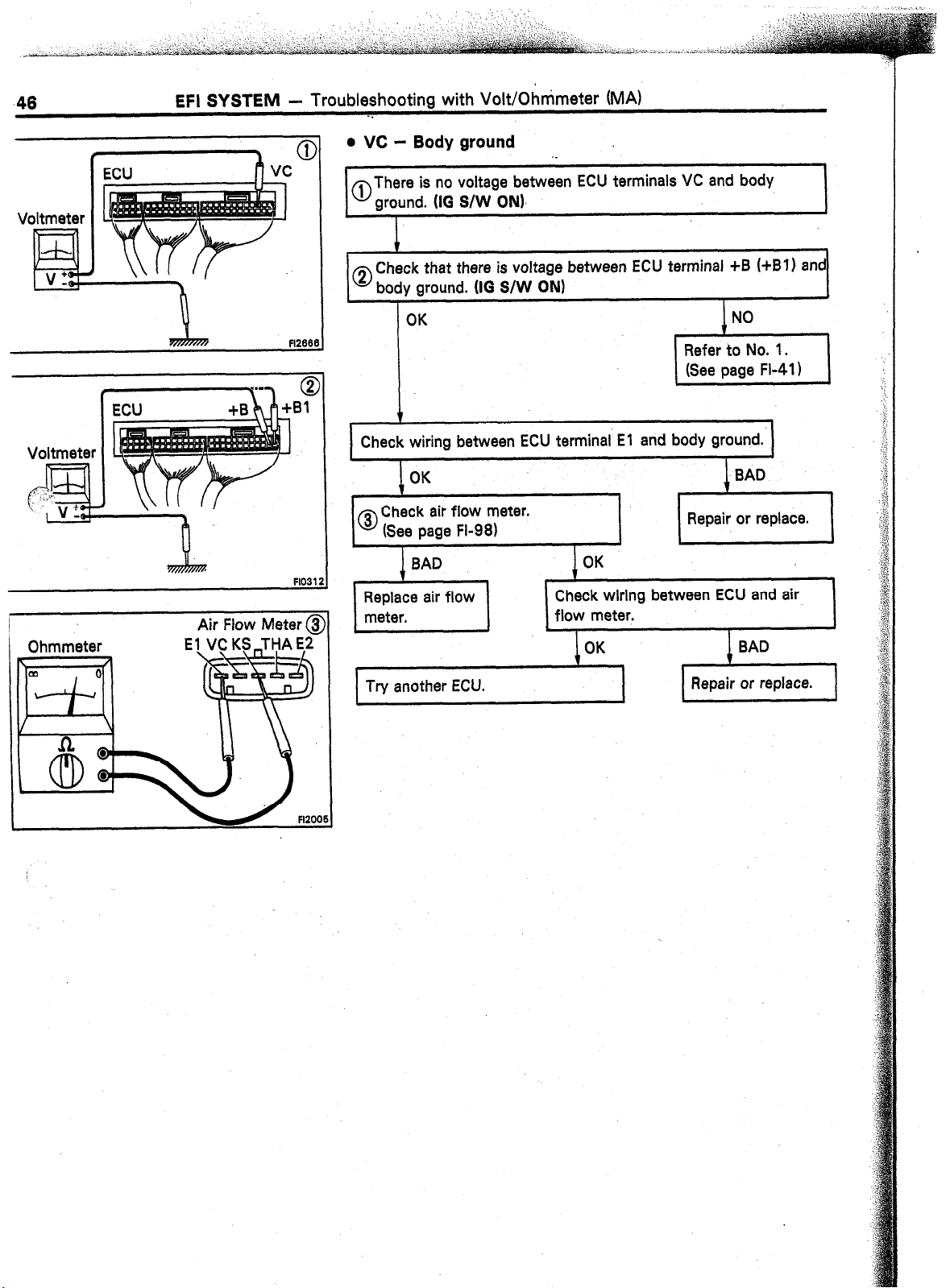
There is no voltage between ECU terminals VC or VS and E2.
0
IIG s/w ON)
i
Check that there is voltage between ECU terminal +B (+Bl)
0
and body ground. (IG S/W ON)
OK
I
1 Check wiring between ECU terminal El and body ground. I 1
t
OK
I
Check air flow meter.
0
(See page FI-96)
Check wiring between ECU and air
flow meter.
OK
,
1 Repair or replace.
NO
Refer to No. 1.
(See page FI-41)
1
Try another ECU.
Repair or replace.
Page 75

EFI SYSTEM
- Troubleshooting with Volt/Ohmmeter (MA)
FI-45
MO.
‘4 -
‘7M-GTE only
I
Terminals
KS - Body
vc -
ground
Body
ground
Trouble
No voltage
Air Flow Meter
_ Ivc
Condition
Ignition’S/W ON
Cranking or running
Ignition S/W ON
. KS - Body ground
STD Voltage
4-6V
2-4V
ECU,
z31,
VC
KS
El
r
FFA7m
F1257i
There is no voltage between ECU terminals KS and body
0
ground. (IO S/W ON)
I
Check that there is voltage between
0
and body ground. (IG S/W ON)
I
OK
i
Check wiring between ECU terminal El and body
0
ground.
L
I
OK
Check air flow meter.
(See page FL981
I I
Check wiring between ECU and air
Repair or replace.
BAD
I
Oh
Try another ECU.
BAD
Repair or replace.
Page 76
46
EFI SYSTEM - Troubleshooting with VoWOhnimeter (MA)
. .
Voltmeter
V:
d
Voltmeter
Air Flow
Meter @
. vc -
al
0
Check wiring between ECU terminal El and body ground.
Body ground
There is no voltage between ECU terminals VC and body
ground. (10 S/W ON),
Check that there is voltage between ECU terminal +B
body ground. (IO
S/W ON)
Check wiring between ECU and air
(+Bl)
and
Try another ECU.
Page 77

EFI SYSTEM - Troubleshooting with Volt/Ohmmeter (MA)
JO.
5
Terminals
No. IO
No. 20 No. 30
Fusible
Link
Battery f
EOl
E02
MAIN 2.OL
8
T
-
I
=
Trouble
No voltage Ignition switch ON
Ignition Switch
I
Condition
c
S-m Voltage
ECU
-“No. 10
-T
9-14v
FIZE
No. 2C
Voltmeter
A\
Solenoid Resistor
nr R?r
There is no voltage between ECU terminal No. 10, No. 20
0
and/or No. 30 and EOl or E02. (IO S/W ON)
1.
Check that there is specified voltage between resistor terminal
0
+B and body ground. STD voltaae:
NO
1
1
Check fuse, fusible links
and ignition switch.
I
Check wiring between
resistor and battery.
Check that there is specified voltage between resistor terminal
@ (No. IO, No. 20 or No. 30) and body ground.
I
OK
1
I
BAD
I
BAD
9 - 14 V
- Repair or replace.
,
- Repair or replace.
j ‘,.“.““!
Check resistance of magnetic coil in
0
I
each lniector.
I
.
Replace resistor.
I 1
J I
.
i
1
I
I
Page 78

FI-48
EFI SYSTEM -
Troubleshooting with Volt/Ohmmeter.(MA)
UO.
6
IM-GE
Terminals
THA - E2
1 I
Air Temp. Sensor
(Air Flow Meter)
Trouble
No voltage IG S/W ON
ECU
+B
(+Bl)
E2
THA
lE1
Condition ._
Intake air temperature 20°C (68°F) 1 -3v
7M-GTE
THA
E2
I
ir Temp. Sensor
iir Flow Meter)
1
I
ST0 Voltage
ECU
CB
-i-B11
l-HA
I
\
.-
7M-GE
‘M-GTE
Ohmmeter
Air Flow Meter
Air Flow Meter
Fl1636
@
There is no voltage between ECU terminals THA and E2.
0
(IG S/W ON)
1
Check that there is voltage between ECU terminal +B (+Bl) and
body ground. (IO S/W ON)
OK
Check wiring between ECU terminal El and body ground.
OK
t
Check air temp. sensor.
0
(See pages FI-96, 98)
L
I
BAD OK
Replace air flow
meter.
L
Check wiring between ECU and air
temp. sensor.
k
I
I I
1 Repair or replace. ]
*
OK
NO
Refer to No. 1.
(See page FI-4 I)
I
I
I/ 1”
THA /
Try another ECU.
Repair or replace.
Page 79

EFI SYSTEM
- Troubleshooting with Volt/Ohmmeter (MA)
-.
Fl-49
No.
7 THW - E2 No voltage
Terminals Trouble
Water Temp. Sensor
ignition switch
ON
1
There is no voltage between ECU terminals THW and E2.
0
(IO S/W ON)
Condition
Coolant temperature 80°C
(1780~) o-q - l-0 V
ECU
iB (+Bll
THW
E2
El
.
STD Voltage
i
Voltmeter
Jf /
n
F1031:
1
Check that there is voltage between ECU terminal +B (+Bl) and
CD
body ground. (IG S/W ON)
OK
Check wiring between ECU terminal El and body ground.
OK
, 1
Check water temp. sensor.
0
(See page FI-1 161
I I
OK
Check wiring between ECU and water
temp. sensor.
OK BAD
Try another ECU.
NO
Refer to No. 1.
(See page FI-41)
Repair or replace.
1
Page 80

1-50
EFI SYSTEM -
Troub&hooting with Volt/Ohmmeter (MA)
No.
6
Terminals
STA - El
Fusible Link
ALT
7M-GE.
I.258
7M-GTE
1 OOA
MAIN 2.01
Battery
Trouble
No voltage
Fusible Ignition
Link
Switch
Condition STD Voltage
Cranking 6-14V
(M/T)
Idal :
Neutral Start S/W
(A/T)
To Circuit
ECU
3TA ,
Starter
a
,ening Relay (STAI
El
loltmeter
V’
lF!L
FlO3:
‘ottmeter 0
Starter
There is no voltage between ECU terminals STA and .El .
0
II0 S/W START)
Check starter OK Check wiring between ECU terminal STA
operation.
BAD
and ignition switch terminal STI.
OK
I
L
BAD
I
1
I
1 Repair or replace.
I
I
0 Check wiring between ECU terminal El and body
I
around.
Check fusible links, battery, wiring,
ignition switch and neutral start
switch.
OK
I
’
Check that there is voltage at STA (50) terminal of starter.
0
(IO S/W START) STD voltage: 6 - 14 V
BAD
e Repair or replace.
1
I
I
OK NO
1 Check starter. 1
Check wiring between ignition switch
terminal ST 1 and starter terminal STA (50).
L
I
Page 81

EFI
SYSTEM
-. Troubleshooting with Volt/Ohmmeter (MA)
FI-51
No. Terminals
9 IGT, IGF - El
I-
i’
Fusible
Link
Battery
Trouble Condition
No voltage Idling
Fusible Link Ignition Switch
AM2 30A
MAIN 2.OL
STD Voltage
0.7 - 1.0 v
ECU
Tachometer
IGF
IGT
El
Voltmeter
It’-
EL
There is no voltage between ECU terminals IGT and El.
0
(Idling)
I
Check that there is voltage between ECU terminal IGT and
0
body ground. (Idling)
NO
I
Check wiring between ECU BAD Repair or
0
terminal El and body ground. replace.
Check fusible links and ignition
switch.
I
1 I I
OK
1
Check distributor or cam position
sensor. (See pages IG- 11, 18)
I
OK
1
I
1
OK
Repair or replace.
BAD
- Repair or replace.
I
I
I
Ohmmeter
Check wiring between ECU and
battery.
I
I
OK
1
BAD
*-Repair or replace.
I L
Repair or replace.
I
Page 82

FI-52
EFI SYSTEM -
Troubleshooting with Volt/Ohmmeter (MA)
._
No.
‘10
‘7M-GTE only
Terminals
lGdA - El
IGdS
No voltage
T
Battery 1
L
I
=
Trouble
Fusible
Link
AM2
30A
Ignition
Switch
AM241G2
0
Condition
idling
7 Tachometer
niter
TO
L
I
=
There is no voltage between ECU terminals IGdA or IGdB and
El. (Idlinal
STD Voltage /
1 -3V
ECU
IGdA
IGdB
El
-l
Joltmeter
F1195
Check that there is voltage between ECU terminal IGdA or
0
IGdB and body ground. (Idling)
,
NO
I ,
Check wiring between ECU
0
terminal El and body ground.
Try another ECU.
Check fusible links and ignition BAD
switch.
c
I
1
I
Check cam position sensor.
(See page IG-18)
I
Check wiring between ECU and
I
batter-v.
I
I
I
OK
1
BAD Repair or
L
- Repair or replace.
I r
Repair or replace.
Repair or replace.
1
9
replace.
1
J
BAD
I
I I
Page 83

EFI SYSTEM
- Troubleshooting with Volt/Ohmmeter (MA)
FI-53
No.
11 ISCl - ISC4 - El No voltage
Terminals
Fusible
Link
Fusible
Link
Trouble Condition
Fuse
EFI 15A
AM2 30A
MAIN 2.OL
h
I
01
STD Voltage
Ignition switch ON
EFI Main Relay
There is no voltage between ECU terminals ISCl - ISC4 and
0
El. (IG S/W ON1
ISC Valve
,
g-14v
ECU
ISCI
ISC2
ISC3
ISC4
+B
+Bl
M-REL
doltmeter
V
PI
Y
@I
Bl
check that there is voltage between ECU terminal +B (+Bl)
0
and body ground. UG S/W ON)
OK
1 Check wiring between ECU terminal El and body ground. 1
OK
I
0
Replace ISC
I Fk-n12
valve.
I
Check ISC valve.
(See page.FI-I 08)
I I
,
Check wiring between ECU and EFI
main relay.
1 Repair or replace. )
I
Fl16431
Page 84

EFI SYSTEM - Troub!eshoo$ng with Volt/Ohmmeter (MA)
. .
JO.
12
Terminals
W - El
FUSE
GAUGE 7.5A
Trouble
No voltage
“CHECK ENGINE”
Wahiing Light
i
f
Combination Mete
Condition
Nq @uble, (“CHECK” engine warning
light off) and engine running
W
El
1
~0 There is no voltage between ECU terminals W and El.
(Idlin$
,
STD Voltage
s-14v
FlO7
Joltmeter
v “_
EL
Voltmeter
.
Check that there is voltage between ECU terminal W and
0
hod\
I
I
Q;
Fl1251
Check GAUGE fuse (7.5A) and “CHECK
ENGINE” warning light.
. .
FH25C
Check wiring between ECU terminal
W and fuse.
I I
0 Check wiring between ECU terminal El and body
I I
Repair or replace.
I
I
1
BAD
*
Repair or replace.
1
I
Page 85

No.
13
Terminals
A/C - El
Trouble
No voltage ,
Condition
Air conditioning ON
STD Voltage
10 - 14 v
ECU
Voltmeter
A/C
Amplifier
T
Lllintl
NC Compressor
There is no voltage between ECU terminals A/C and El.
0
(Air conditioning ON)
i
I
Check that there is voltage between ECU terminal A/C and 1
0
bodl y ground.
I
NO OK .‘.
NC
El
I
Voltmeter
Ohmmeter
F1125
Check wiring between ECU terminal El and body
0
ground.
BAD
Check that there is voltage between
amplifier terminal and body ground.
I
OK
1
Check wiring between amplifier and BAD
ECU or compressor.
BAD
terminal A/C and
c Repair or replace.
c
* Repair or replace.
Page 86

;6
EFI SYSTEM .L Troubleshooting with VoWOhmmeier (MA)
0.
r4
Terminals
- E2
HAC
7M-GTE only
To Air Flow Meter-
Her Flow Meter
Trouble ‘Z’ ‘f .: ‘I *-
;> :
No voltage
1 ‘Ig+i@
S/W ON
1 HAC
bE2.
.,~ .._ .,_
I... ~ _ . . ., , .
,.;_
ECU
Condition
540 mmHg (2l,.26 h.Hg, 72:O !Pa)
750 mmHg (29.53 in.Hg, 100.0 kPa)
2,000 0 Alitude (m)
1,000
STD Voltage
Approx. 2.8 V
Approx. 3.8 V
FI1995Fil99
,..
,. . . . \
Voltmeter
1,
.v ‘_
EL .
E2 VC
.._
itage between ECU terminal HAC and E2.
.,, ”
Check that there is voltage between ECU tdrminal VC and
body ground. (IG S/W ON)
Refer to No. 2.
(See page FI-43)
Check wiring between ECU terminal El and body ground.
.
0 Check HAC sensor.
(See page FI-121)
. ...<,
4
Repair or replace.
BAD OK
Replace HAC
Check wiring between ECU and HAC
sensor. sensor.
OK
Try another ECU.
I
Repair or replace.
BAD
BAD
b
FI199
Page 87

EFI SYSTEM
- Troubleshooting with Volt/Ohmmeter (MS)
-.
TROUBLESHOOTING WITH
VOLT/OHMMETER (MS)
FI-57
NOTE: The following troubleshooting procedures are designed for inspection of each separate system, and therefore the actual procedure
may vary somewhat.. However, troubleshooting
should be performed refering to .the inspection
methods described in this manual.
Before beginning,inspection, it is best to first make
a simple check of the fuses, fusible links and the
condition of the connectors.
.._
LOCATIoN- OF FUSES AND FUSIBLE LINKS
Junction Block and Relay Block Cassettes
The following troubleshooting procedures are
based on the supposition that the trouble ‘lies in
either a short or open circuit in a component outside the computer or a short circuit within the
computer.
If engine trouble occurs even though proper.
operating voltage is detected in the computer connector, then it can be assumed that the ECU is
faulty and should be replaced.
Page 88

jS EFI SYSTEM - Troubleshooting with Volt/Ohmmeter (MS)
-.
EFI SYSTEM CHECK PROCEDURE
._
PREPARATION
(a) Disconnect the connectors from the ECU.
(b) Remove the locks as shown in the illustration so that
the tester probe(s) can easily come in.
CAUTION: Pay attention to sections “A” and “B” in
the illustration which can be easily broken,
0
“B”
Fl294.
(c) Reconnect the connectors to the ECU.
NOTE:
’
0 Perform ail voltage measurements with the connectors
connected.
ECU
0 Verify that the battery voltage is 1 IV or above when
the ignition switch is at “ON”.
Using a voltmeter with high-impedance (10 kQ/V mihimum),
measure the voltage at each terminal of the wiring connectors.
Terminals of ECU
rmbol
EOI POWER GROUND NE DISTRIBUTOR ACPS A/C PRESSURE SWITCH
co2 POWER GROUND El COMPUTER GROUND SPD SPEEDOMETER
o. 10 INJECTOR (No. 1 and 4) VF CHECK CONNECTOR ECT ECT COMPUTER
o. 30 INJECTOR (No. 3 and 5)
o. 20 INJECTOR (No. 2 and 6)
ELS
FPU
ACV VSV (A/R CONTROL) THW WATER TEMP. SENSOR L3 ECT COMPUTER
SC 1 ISC MOTOR NO. 1 COIL
IGT IGNITER
SC- ISC MOTOR NO. 2 COIL
ISC3 ISC MOTOR NO. 3 COIL
ISC4 ISC MOTOR NO. 4 COIL
IGF
G2 1 DISTRIBUTOR 1 STA 1 STARTER SWITCH
Gl 1 DISTRIBUTOR
ZU Terminals
Terminal Name Symbol Terminal Name
GO
TE2 CHECK CONNECTOR Ll
DEFOGGER SWITCH
HEADLIGHT SWITCH
VSV (FPU) KNK KNOCK SENSOR FPR FUEL PUMP RELAY
IGNITER
TEl CHECK CONNECTOR L2
IDL
THA AIR TEMP. SENSQR
VTA THROlTLE POSITION SENSOR IG SiW IGNITION SWITCH 3
vcc
1 NSW 1 NEUTRALSTARTSWITCH
DISTRIBUTOR ACR A/C COMPRESSOR
THROTTLE POSITION SENSOR
vs AIR FLOW METER Bl EFI MAIN RELAY
AIR FLOW METER
THROTTLE POSITION SENSOR
E2
SENSOR GROUND
Symbol Terminal Name
ECT COMPUTER
ECT COMPUTER
W
WARNING LIGHT
M-REL EFI MAIN RELAY (COIL)
BATT BATTERY
B
EFI MAIN RELAY
Page 89

EFI SYSTEM - Ttpbleshooting with Volt/Ohmmeter (MS)
Voltage at ECU Wiring Connectors
FL59
IO.
Terminals
I
BATT - El
IG S/W - El
M-REL - El
2P-
UTA - E2
I
3
US - E2
Condition STD Voltage ’
ignition S/W ON
Throttle valve
Ignition S/W ON .
Throttle valve fully closed
Throttle valve fully open
Ignition S/W ON Measuring plate fully closed
Measuring plate fully open
Idling 2-4
3,000 rpm 0.3 - 1 .o
open 10 - 14
10 - 14
10 - 14
4-6
0.1 - 1.0
4-5
4-6
4-5
0.02 - 0.08
See page
FI-60
FI-6 1
FI-62
FI-63
FI-64
Fl-65
THA - E2
THW - E2
.B / IGF, IGT - El
ISCI
9
10
I
ECU Terminals
lSC4
W - El
- El
Ignition S/W ON 9
Ignition S/W ON Intake air temperature 20°C (68°F) 1
Ignition S/W ON
No trouble (“CHECK-ENGINE” warning light off) and
engine running
Coolant temperature 80°C (176°F) 0.1 - 1.0
Cranking
Idling 0.7 - 1.0
Ignition S/W ON
- 14 FI-66
-3
6 - 14
9 - 14
8 - 14
Fl-6.7
FI-68
FI-69
Fl-70
FI-7 1
Fl;72
Page 90

FI-60
I
EFI SYSTEM
- Troubleshooting with VoW6hmmeter (MS)
-.
No.
1
-‘- Battery
Terminals Trouble Condition .
IO S/W - El
M-REL - El No voltage Ignition switch ON
BATT - El No voltage
No voltage
B(B1) -El No voltage Ignition switch ON
@z
. BATT - El
Ignition switch ON lo-14v
STD Voltage
lo- 14v
IO- 14v
10 - 14 v
BATT ’
Bl
B
M-REL
IG S/W
El
I
ECU
ECU
Fl275:
Fl275,
w
@There is no voltage between ECU terminals BATT and El.
I
Check that there is voltage between ECU terminal BATT and
0
body ground.
I
NO
Check wiring between ECU terminal El and body
0
ground.
OK
1
Check wiring between ECU terminal BAD
and battery.
OK
BAD
Replace.
w Repair or replace.
I
I
Fl275
Page 91

EFI SYSTEM
- Troubleshooting with Volt/Ohmmeter (MS)
-.
FI-61
ECU
@
. IG S/W - El
There is no voltage between ECU terminals IG S/W and El.
0
(IG S/W ON)
._
I
Check that there is voltage between ECU terminal IG S/W and
0
body ground. (10 S/W ON)
,
Check wiring between ECU terminal El and body
ground.
Check fuse, fusible link and
ignition switch.
l
M-REL - El
1
,
I
BAD
) Repair or replace.
I
1
I
I
I
I
ECU
ECU
I
There is no voltage between ECU terminals M-REL and El.
0
(IG S/W ON)
1
Check that there is voltage between ECU terminal M-REL and
3
body ground. (IG S/W ON)
NO
Che’ck wiring between ECU terminal El and body
ground.
Try another ECU.
F
Check EFI main relay and wiring
harness.
OK
OK BAD
1
I
BAD
Replace or repair.
I I
c Replace.
‘
Page 92

FI-62
EFI SYSTEM
- Troubleshooting with Volt/Ohmmeter (MS)
0 B (91) - El -’
ECU
Il--crl
I
I ECU
-- -
I
I’
I
II
R%
fl2911
@I
F12767 I
There is no voltage between ECU terminals B (Bl) and El.
0
(IG S/W ON)
I
t
,
Check that there is voltage between ECU terminal B (Bl) and
0
body ground. (IG
I
I
NO
Check wiring between ECU terminal El and body
ground.
Try another ECU.
Check fuse, fusible link and wiring BAD
harness.
I
OK
1
Check EFI main relay.
(See page FI-1 12)
OK
I
S/W ON)
OK
- El trouble
I
I
1 Replace‘or repair. ]
* Repair or replace.
BAD
w Replace.
I
I
I
Page 93

EFI SYSTEM - Troubleshooting with Volt/Ohmmeter (MS)
FI-63
No. 1
2
I
Terminals 1 Trouble 1
IDL
- E2 Throttle valve open
vcc - E2
No voltage
VTA - E2
ECU
Ignition
switch ON
. IDL - E2
0
There is no voltage between ECU terminals IDL and E2.
(IO S/W ON) (Throttle valve open)
I
Condition
Throttle valve fully closed 0.1 - l.OV
Throttle valve fully open
1
Check that there is voltage between ECU terminal B (Bl) and
0
body ground.
(IO S/W ON)
ECU .s
S-m Vnlttlnq
--- ‘-‘-P-~
10 - 14 v
4-6V
4-!iv
r
Fl136
I
I
ECU
Y ,
F12767
NO
, 1
Check wiring between ECU terminal El and body
I I
1 ground.
Try another ECU.
OK
OK
BAD
Repair or replace.
I
I
i
Refer to No. 1. BAD
(See page FI-62)
t
OK
I@ Check throttle position sensor,
BAD
*
Replace or repair Check wiring between ECU and
throttle position sensor.
p Replace or repair.
,
]
OK
throttle position sensor.
1
OK
Try another ECU.
t
t
BAD
I
1
‘!
t
Page 94

FI-64 EFI SYSTEM -
Troubleshooting with Volt/Ohmmeter
(MS)
. VCC -
There is no voltage between ECU terminals VCC and E2.
0
1
Check that there is voltage between ECU terminal B (Bl) and
body ground. II0 S/W ON1
0
1 Repair or replace.‘ /
t I
Try another ECU.
l
VTA - E2
I- I
0
E2
(IO S/W ON)
I
OK
Check throttle position sensor. Refer to No. 1.
(See page FL102)
There is no specified voltage at ECU terminals VTA and E2.
(IG S/W ON)
.
7
(See page FL62)
k
OK
I
,
Check wiring between ECU and throttle
position sensor.
OK
, 1 BAD ,
1 Rwe;ix3;.or replace ]
I
Check that there is voltage between ECU terminal VCC and E2.
0
(IO S/W ON)
I 1
OK
I
I
[@ Check thrc1
I
OK
1
I ‘1 4
Check wiring between ECU and
throttle position sensor.
I
OK
1
1 Try another ECU.
1
BAD 4 Repair or replace. 1
BAD
- Repair or replace.
I
Fl162
Page 95
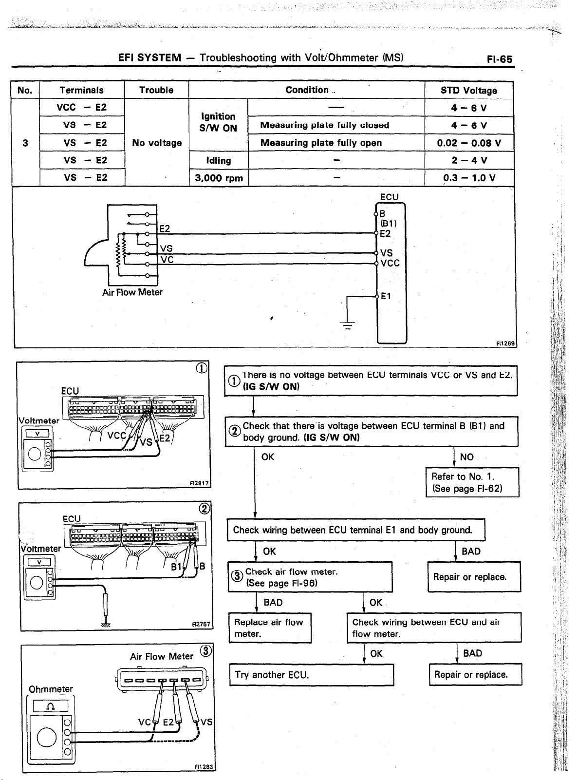
EFJ SYSTEM
- Troubleshooting with Volt/Ohmmeter (MS)
-_
FI-65
No.
3 vs - E2 No voltage Measuring plate fully open
Tprminals Trouble Condition ._
vcc
- E2
vs
- E2
vs
- E2 Idling
vs
- E2 3,000 rpm
0 ^,
-’ E2
r; wt.
I ’
Air Flow Meter Air Flow Meter
I
Ignition
SIW ON
Measuring plate fully closed
# #
I- I-
= =
I
ECU
I
El
I
STD Voltage
4-6V
4-6V
0.02 - 0.08 V
2-4V
0.3 - 1.0 v
Fl126!
ECU
Air Flow Meter
There is no voltage between ECU terminals VCC or VS and E2.
0
(IG S/W ON)
1
Check that there is voltage between ECU terminal B @I) and
0
body ground. (IG S/W ON)
c
OK
7
Check wiring between ECU terminal El and body ground.
OK BAD
Check air flow meter.
0
(See page FI-96)
,+, ,I,
Check wiring between ECU and air
NO
Refer to No. 1.
(See page FI-62)
Repair or replace.
7
Try another ECU.
I
FIl28:
Page 96

FI-66
EFI SYSTEM -
Troubleshooting with VoltjOhrnmeter (MS)
-.
Ua. I
4
Terminals 1 Trouble 1
No. 10
No. 20 No. 30
EOI
E02
Battery i
No voltage
T
+?
Condition
ignition switch ON g-14v
I STD Voltage
ECU
IG S/W
‘No. IO
‘No. 20
‘No. 30
IEOI
I E02
c
&
=
FU.9
mb
Fl291
There is no voltage between ECU terminal No. IO, No. 20
0
and/or No. 30 and EOl or E02. (IG S/W ON)
‘
J
Check that there is specified voltage between resistor
0
terminal +B and body ground. STD voltage: 9 - 14 V
Check wiring between
resistor and battery.
Check that there is specified voltage between resistor terminal
@ (No. 10, No. 20 or No. 30) and body ground.
STD voltage: 9 - 14 V
I
Check resistance of magnetrc co11 rn
e,+i
BAD
-t Repair or replace.
I
Check wiring between ECU and
I
iniector. I I
Replace injector,
Page 97

No.
Terminals Trouble Condition STD Voltage
I
5 THA - E2
I I I I
No voltage ON
I
Ignition switch Intake air temperature 20°C
I
(66°F)
1 -3v
0 ”
L -
,’ E2
Air Temp. Sensor
(Air Flow Meter)
0 6
(B?)
(5E2
( THA
o El
There is no voltage between ECU terminals THA and E2.
0
(IG S/W ON)
I
Check that there is voltage between ECU terminal B (Bl 1 and
0
body ground. (IG S/W ON)
ECU
fl275'
Air Flow Meter ’
OK NO
Refer to No. 1.
(See page FI-62)
1
Check wiring between ECU terminal El and body ground.
OK
Check air temp. sensor.
0
(See page FI-96)
BAD
OK
Repair or replace.
c
Replace air frow Check wiring between ECU and air
meter. temp. sensor.
BAD
Try another ECU.
OK
1 Repair or replace. 1
I
Page 98

EFI SYSTEM
- Troubleshooting with Voltkhmmeter (MS)
-.
No. 1
6 THW - E2 .No voltage
Terminals
Trouble
I
Water Temp. Sensor
I
Ignition switch Coolant temperature 80°C
ON
Condition ._
(, 760F) 0.1 - 1.0 v
ECU
5 031)
THW
E2
:1
.
STD Voltage
I
ECU
There is no voltage between ECU
0
(IG S/W ON)
I-
Check that there is voltage between ECU terminal B (61) and
0
:.
I
body ground. (IG S/W ON) -
OK NO
I 8 1
I
Check wiring between ECU terminal El and body ground.
Check water temp. sensor.
BAD
Replace water
temp. sensor.
I
Check wiring between ECU and water
temp. sensor.
I terminals THW and E2.
OK
OK BAD
Refer to No. 1.
(See page FL62)
I
. -
I
BAD
I
Repair or replace.
I
1
I
I
Try another ECU.
1 Repair or replace. 1
Page 99

EFI SYSTEM - Troubleshooting with Volt/Ohmmeter (MS)
FI-69
No. 1 Terminals 1
1 STA - El No voltage Cranking
7
Fusible Link
AM1 40A
ALT 1OOA
Trouble 1 Coridition
Ignition Switch
l~ol
AMIj
Fusible
Link
lsT’ST 7.5A
I I
MAIN
%
,
Fuse
“V
Neutral Start
,
(M/T)
r
Battery
1
,Opening
Starter
Relay
To Circu
Relay
1 .STD Voltage
6-14V
ECU
STA
El
ECU
Ft275!
There is no voltage between ECU terminals STA and El.
0
(IO S/W START)
I
Check starter OK
operation.
BAD
Check wiring between ECU terminal El and body
0
ground.
Try another ECU.
v
Check fusible links, battery, wiring,
ignition switch and neutral start
switch.
I
OK
Check &ring between ECU terminal STA
and ignition switch terminal STI.
OK BAD
Repair or replace.
t
OK
Repair or replace.
BAD
c Repair or replace.
BAD
Check that there is voltage at STA (50) terminal of starter.
0
OG S/W START) STD voltage: 6 - 14 V
OK
c
Check starter.
Check wiring between ignition switch
terminal ST1 and starter terminal STA (50).
NO
Page 100

No.
8
EFI SYSTEM - Troubleshooting with Volt/Ohmmeter (MS)
Terminals Trouble
IGT, IGF - El No voltage
Ignition SW
. .
Condition
Idling -- 0.7-l.OV
STD Voltage
Fusible
Link 30A
AM2
a
F12771
There is no voltage between ECU terminals IGT and El.
0
(Idling)
Check that there is voltage between ECU terminal IGT and
0
body ground. (Idling)
NO OK
0
I
Check wiring between ECU BAD Repair or
terminal El .and body ground. replace.
ECU
Y ,
&z
F1277
8
F12755
OK
I
1 Try another ECU.
Check fusible link and ignition
switch.
I I
OK
I
T
I
Check wiring between ECU and
battery.
I
I
I
BAD
BAD
1 I I
BAD
BAD
I 1
Repair or replace.
I
c Repair or replace.
Repair or replace.
I
 Loading...