

Page 1

WORKSHOP MANUAL
2011MY UC SERIES
ENGINE
4JJ1 MODEL
SECTION 6
Isuzu Motors Limited
E-Solutions &
Service Marketing Dept.
Page 2

Page 3

SECTION 6A
ENGINE MECHANICAL (4JJ1)
TABLE OF CONTENTS
ISUZU DIESEL ENGINE (4JJ1) ......................... 6A-3
Service Precautions ........................................ 6A-3
Trouble Shooting ............................................. 6A-8
Main Data and Specifications.......................... 6A-13
Special Tools................................................... 6A-14
Engine Assembly................................................ 6A-15
Removal .......................................................... 6A-15
Installation ....................................................... 6A-17
Special Tools................................................... 6A-19
Engine Mount ..................................................... 6A-20
Components.................................................... 6A-20
Removal .......................................................... 6A-21
Installation ....................................................... 6A-21
Torque Specifications...................................... 6A-22
Special Tools................................................... 6A-22
Cylinder Head Cover .......................................... 6A-23
Components.................................................... 6A-23
Removal .......................................................... 6A-24
Installation ....................................................... 6A-25
Intake Manifold ................................................... 6A-26
Components.................................................... 6A-26
Removal .......................................................... 6A-27
Installation ....................................................... 6A-28
Torque Specifications...................................... 6A-30
Turbocharger and Exhaust Manifold .................. 6A-31
Components.................................................... 6A-31
Removal .......................................................... 6A-32
Inspection ........................................................ 6A-34
Installation ....................................................... 6A-35
Torque Specifications...................................... 6A-38
Timing Gear Train .............................................. 6A-39
Components.................................................... 6A-39
Removal .......................................................... 6A-40
Disassembly .................................................... 6A-42
Reassembly..................................................... 6A-42
Inspection ........................................................ 6A-43
Installation ....................................................... 6A-44
Torque Specifications...................................... 6A-47
Camshaft Assembly ........................................... 6A-48
Components.................................................... 6A-48
Removal .......................................................... 6A-49
ENGINE MECHANICAL (4JJ1) 6A-1
Disassembly.................................................... 6A-50
Reassembly .................................................... 6A-52
Installation ....................................................... 6A-53
Torque Specifications...................................... 6A-55
Special Tools................................................... 6A-55
Valve Stem Seal and Valve Spring .................... 6A-56
Components.................................................... 6A-56
Removal .......................................................... 6A-57
Inspection........................................................ 6A-58
Installation ....................................................... 6A-59
Special Tools................................................... 6A-60
Cylinder Head..................................................... 6A-61
Components.................................................... 6A-61
Removal .......................................................... 6A-61
Disassembly.................................................... 6A-69
Inspection........................................................ 6A-71
Reassembly .................................................... 6A-76
Installation ....................................................... 6A-77
Torque Specifications...................................... 6A-88
Special Tools................................................... 6A-88
Piston and Connecting Rod................................ 6A-89
Components.................................................... 6A-89
Removal .......................................................... 6A-89
Disassembly.................................................... 6A-90
Reassembly .................................................... 6A-94
Installation ....................................................... 6A-95
Torque Specifications...................................... 6A-97
Special Tools................................................... 6A-97
Flywheel ............................................................. 6A-98
Components.................................................... 6A-98
Removal .......................................................... 6A-98
Inspection........................................................6A-100
Installation .......................................................6A-100
Torque Specifications...................................... 6A-102
Special Tools................................................... 6A-102
Gear Case Assembly .........................................6A-103
Components....................................................6A-103
Removal ..........................................................6A-104
Installation .......................................................6A-105
Torque Specifications...................................... 6A-107
Page 4

6A-2 ENGINE MECHANICAL (4JJ1)
Crankshaft Front Oil Seal ...................................6A-108
Components....................................................6A-108
Removal ..........................................................6A-108
Installation .......................................................6A-109
Torque Specifications......................................6A-110
Special Tools...................................................6A-110
Crankshaft Rear Oil Seal ...................................6A-111
Components....................................................6A-111
Removal ..........................................................6A-112
Installation .......................................................6A-112
Special Tools...................................................6A-113
Crankshaft ..........................................................6A-114
Components....................................................6A-114
Removal ..........................................................6A-115
Disassembly ....................................................6A-116
Reassembly.....................................................6A-116
Inspection ........................................................6A-116
Installation .......................................................6A-120
Torque Specifications......................................6A-123
Cylinder Block ....................................................6A-124
Components....................................................6A-124
Removal ..........................................................6A-124
Inspection ........................................................6A-125
Installation .......................................................6A-126
Lubrication System.............................................6A-128
Service Precautions ........................................6A-128
Functional Check ............................................6A-129
Oil Filter Cartridge ..............................................6A-131
Components....................................................6A-131
Removal ..........................................................6A-131
Installation .......................................................6A-131
Special Tools...................................................6A-132
Oil Filter Assembly and Oil Cooler .....................6A-133
Components....................................................6A-133
Removal ..........................................................6A-133
Installation .......................................................6A-135
Crank Case and Oil Pan.....................................6A-137
Components....................................................6A-137
Removal ..........................................................6A-138
Disassembly ....................................................6A-139
Reassembly.....................................................6A-139
Installation .......................................................6A-140
Torque Specifications......................................6A-142
Oil Pump ............................................................6A-143
Components....................................................6A-143
Removal ..........................................................6A-143
Disassembly....................................................6A-145
Reassembly ....................................................6A-145
Inspection........................................................6A-145
Installation .......................................................6A-146
Oil Pressure SW ................................................6A-149
Components....................................................6A-149
Removal ..........................................................6A-150
Inspection........................................................6A-150
Installation .......................................................6A-150
Circuit check.................................................... 6A-150
Air Cleaner Element ........................................... 6A-151
Removal ..........................................................6A-151
Cleaning ..........................................................6A-151
Installation .......................................................6A-151
Page 5

ENGINE MECHANICAL (4JJ1) 6A-3
f
y
r
r
r
r
A
f
r
A
y
y
r
r
r
ISUZU DIESEL ENGINE (4JJ1)
Service Precautions
Matters that require attention in terms o
maintenance
To prevent damage to the engine and ensure reliabilit
of its performance, pay attention to the following in
maintaining the engine:
• When lifting up or supporting the engine, do not
apply a jack on the oil pan.
When taking down the engine on the ground, do
not make the bearing surface of the oil pan touch
the ground directly. Use a wooden frame, fo
example, to support the engine with the engine
foot and the flywheel housing.
Because there is only a small clearance between
the oil pan and the oil pump strainer, it can
damage the oil pan and the oil strainer.
• When the air duct or air cleaner is removed, cove
the air intake opening to prevent foreign matte
from getting into the cylinder. If it gets
contaminated, it can considerably damage the
cylinder and others while the engine is operating.
• When maintaining the engine, never fail to remove
the battery earth cable. If not, it may damage the
wire harness or electrical parts. If you need
electricity on for the purpose of inspection, fo
instance, watch out for short circuits and others.
•
pply engine oil to the sliding contact surfaces o
the engine before reassembling it. This ensures
adequate lubrication when the engine is first
started.
• W hen valve train parts, pistons, piston rings,
connecting rods, connecting rod bearings o
crankshaft journal bearings are removed, put them
in order and keep them.
• When installing them, put them back in the same
location they were removed from.
• Gaskets, oil seals, O-rings, etc. must be replaced
with new ones when the engine is reassembled.
•
s for parts where a liquid gasket is used, remove
an old liquid gasket completely and clean it up
thoroughly so that no oil, water or dust is clinging
to them. Then, apply the designated liquid gasket
to each place anew before assembly.
• Surfaces covered with liquid gasket must be
assembled within 5 minutes of gasket application.
If more than 5 minutes has elapsed, remove the
existing liquid gasket and apply a new liquid
gasket.
• When assembling or installing parts, fasten them
with the prescribed tightening torque so that the
are installed properly.
Matters that require attention in specifically dealing
with this engine.
Holes or clearances in the fuel system, which serve as
a passage of fuel, including the inside of the injector,
are made with extreme precision. For this reason, the
are highly sensitive to foreign matter and, if it gets in, it
can lead to an accident on the road, for instance; thus,
make sure that foreign matter is prevented from getting
in.
When servicing the fuel system, every precaution must
be taken to prevent the entry of foreign material into the
system.
• Before beginning the service procedure, wash the
fuel line and the surrounding area.
• Perform the service procedures with clean hands.
Do not wear work gloves.
• Immediately after removing the fuel hose and/o
fuel pipe, carefully tape vinyl bags over the
exposed ends of the hose or pipe.
• If parts are to be replaced (fuel hose, fuel pipe,
etc.) do not open the new part packaging until
installation.
Work procedure
• The fuel opening must be quickly sealed when
removing the fuel pipe, injection pipe, fuel injector,
fuel supply pump, and fuel rail.
• The eyebolts and gasket must be stored in a clean
parts box with a lid to prevent adhesion of foreign
matter.
• Fuel leakage could cause fires. Therefore, afte
finishing the work, wipe off the fuel that has leaked
out and make sure there is no fuel leakage afte
starting the engine.
Page 6
6A-4 ENGINE MECHANICAL (4JJ1)
r
f
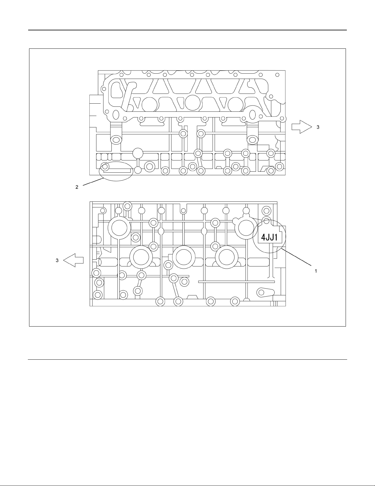
How to read the model
Legend
1. Engine Model (Stamped)
2. Engine Number (Stamped)
Explanation of functions and operations
Electronic engine control
With the control unit, the range from injection to ai
intake/exhaust, including fuel injection quantity, injection
timing, intake air restriction, EGR, and idling rpm, is
controlled.
Piston
The piston is aluminum-alloy and a thermal flow piston
with a strut cast, while the combustion chamber is a
round reentrant type.
3. Front
Cylinder head
The cylinder head is aluminum-alloy and there are 4
valves per cylinder. The angular tightening method o
the cylinder head bolt further increases reliability and
durability.
RTW56ALF001501
Page 7
ENGINE MECHANICAL (4JJ1) 6A-5
r
y
r
EGR system
Based upon data, including water temperature, engine
speeds or engine loads, it is controlled via Engine
Control Module (ECM) to purify exhaust by recycling
part of it.
Its main components include an EGR valve, an EGR
cooler and various sensors.
Connecting rod cap bolt
The angular tightening method of the connecting rod
cap bolt further increases reliability and durability.
Fuel rail-type electronic control injection system
The fuel rail-type electronic control injection system is
composed of a fuel supply pump that sets the target
pressure of high-pressure fuel and supply it, a fuel rail
that measures such high-pressure fuel and a fuel
injector that turns it into a fine spray and injects it. Each
is controlled via ECM based upon various signals, while
injection timing or fuel injection quantity is controlled
under every possible driving condition.
Fuel injector
The fuel injector is a 6-hole nozzle that adjusts fuel
injection quantity or injection timing by opening o
closing an electromagnetic valve on the head of the fuel
injector.
ECM corrects the dispersion of fuel injection quantit
between fuel injector according to ID code data in
memory. At the replacement of fuel injector, ID code
data should be stored in ECM.
Fuel filter with sedimenter
It is a fuel filter with sedimenter that gets rid of water by
making use of the difference in specific gravity between
light oil and water, which comes with an indicator that
notifies you that it is filled with water.
Preheating system
The preheating system consists of the ECM, the glow
relay, glow plugs and the glow indicator lamp. The
preheating system is operated when the engine coolant
temperature is low, and makes the engine easy to start.
Lubrication system
It is an oil filter with full-flow bypass, which uses a
water-cool oil cooler and oil jet to cool the piston.
Functional inspection
Inspection/adjustment of valve clearance
1. Inspection of valve clearance
• Remove the fuel injector harness assembly.
• Remove the leak off hose.
• Remove the cylinder head cover.
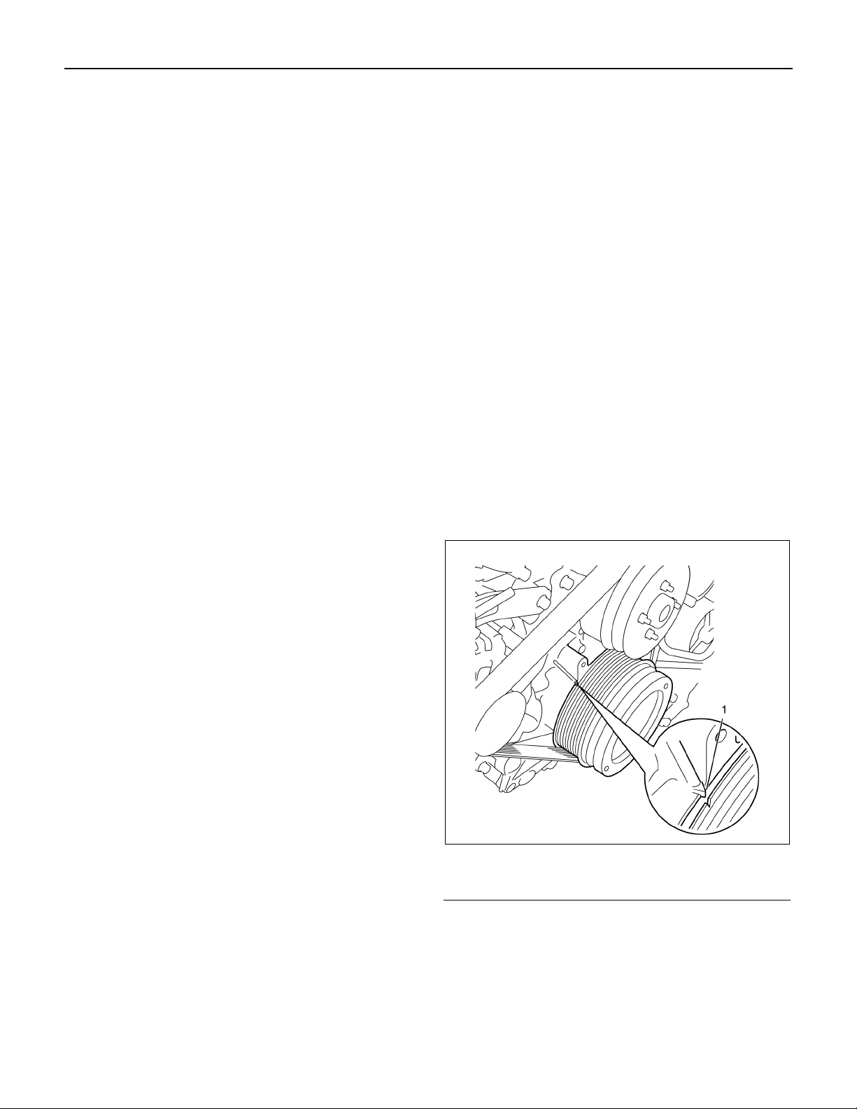
• Rotate the crankshaft to make the No.1
cylinder meet the compression top dead cente
(TDC).
RTW76ASH001301
Legend
1. TDC
Page 8
6A-6 ENGINE MECHANICAL (4JJ1)
f
f
• Insert a 0.15 mm (0.006 in) thickness gauge
between the roller of the rocker arm and the
camshaft to tighten up the adjusting screw o
the rocker arm. When the movement of the
thickness gauge becomes tight, fasten the
adjusting screw nut of the rocker arm.
Valve clearance mm (in)
Intake valve 0.15 (0.006)
Exhaust valve 0.15 (0.006)
Note:
Adjust while cold.
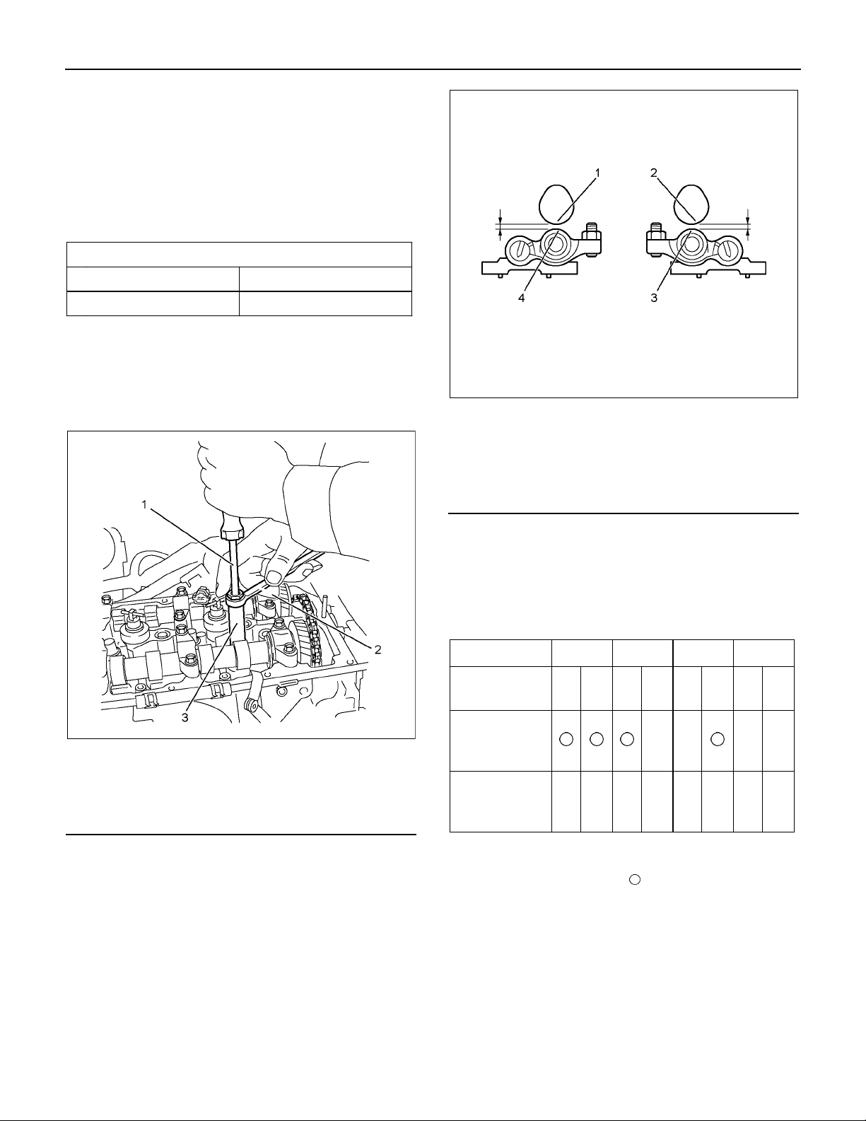
2. Adjustment of valve clearance
• Loosen each adjusting screw of the rocker arm
completely.
Legend
1. Cam; Exhaust
2. Cam; Intake
3. Roller; Intake
4. Roller; Exhaust
LHW71BSH001201
Legend
1. Screwdriver
2. Ring Spanner
3. Valve Clearance Adjust Nut Wrench
Special tool
Valve clearance adjust nut wrench: 5-8840-2822-0
• Insert a 0.15 mm (0.006 in) thickness gauge
between the roller of the rocker arm and the
camshaft to tighten up the adjusting screw o
the rocker arm. When the movement of the
thickness gauge becomes tight, fasten the
adjusting screw nut of the rocker arm.
RTW56ASH003701
Tightening torque:
Rocker arm adjustment screw nut
18 N⋅⋅⋅⋅m (1.8 kg⋅⋅⋅⋅m / 13 lb ft)
Adjustment table
Cylinder No. 1 2 3 4
Valve
arrangement
No. 1 cylinder
Compression
TDC
No. 4 cylinder
Compression
TDC
• If the No.1 cylinder is the compression TDC, adjust
a valve clearance with
and if the No. 4 cylinder is the compression TDC,
adjust that with × mark.
• Install the cylinder head cover.
Refer to "Cylinder Head Cover."
• Install the leak off hose.
• Install the fuel injector harness assembly.
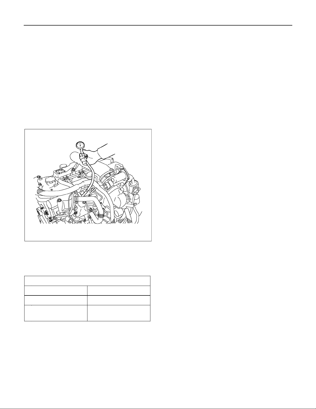
Compression pressure inspection
• Warm up the engine.
• Disconnect the negative battery cable.
IN EX IN EX IN EX IN EX
× × × ×
mark given on the table
Page 9
ENGINE MECHANICAL (4JJ1) 6A-7
y
• Remove the all glow plugs.
Note:
When the harness connector is removed, ECM judges
that it broke down and DTC is recorded. Upon
completion of measurement, never fail to clear the
memory of the ECM.
(For how to clear the memory of the ECM, refer to
“ENGINE CONTROL SYSTEM” Section)
• Connect the negative battery cable.
• Turn on the starter to emit foreign matter within the
cylinders.
• Install an adapter and a gauge of a compression
gauge of the special tool.
A list of defective phenomena
• Engine does not turn over.
• Engine turns over but does not start.
• Excessive black exhaust smoke.
• Excessive white exhaust smoke.
• Engine knocking.
• Abnormal engine rotation.
• Abnormal battery charging.
• Turbocharger trouble shooting.
RTW56ASH003801
Compression gauge: 5-8840-2675-0
Gauge adapter: 5-8840-2815-0
• Turn on the starter to inspect compression
pressure.
Compression pressure MPa(psi)/200rpm
Standard 2.84 − 3.24 (412 − 469)
Limit 1.96 (284)
Differences among
the cylinders
294 kPa (43)
• Measure each cylinder one by one.
Note:
To keep engine speed at 200 rpm or more, use full
charged batteries.
• Remove a compression gauge of the special tool.
• Disconnect the negative battery cable.
• Install the glow plugs.
• Connect the negative battery cable.
Page 10
6A-8 ENGINE MECHANICAL (4JJ1)
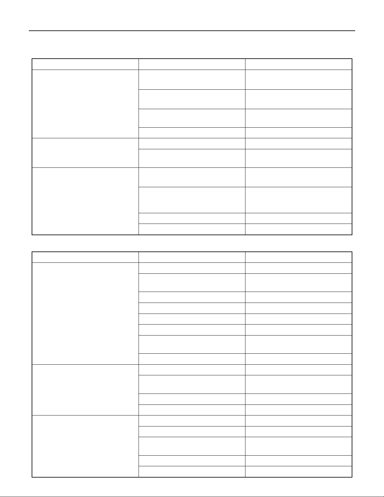
Trouble Shooting
Engine does not turn over
Condition Possible Cause Correction
Starter motor does not rotate
flywheel
Starter motor pinion meshed with
ring gear but does not rotate
Engine turns over but does not start
Dead or weak battery Charge battery
Replace battery
Incomplete circuit Connector wiring and/or connectors
Repair
Starter motor brushes stuck, worn,
or broken
Starter motor internal damage Repair motor
Ring gear abrasion Replace ring gear Starter motor not meshed with
Magnetic switch (starter motor) not
properly adjusted
Dead or weak battery Charge battery
Insufficient contact pressure
between starter motor brushes and
commutator
Armature (starter motor) stuck Repair armature
Engine internal damage (Seizure) Repair engine
Replace brushes
Adjust magnetic switch
Replace battery
Adjust pressure
Condition Possible Cause Correction
Fuel is not delivered to fuel supply
pump
Fuel is delivered to fuel supply
pump
Insufficient or unstable fuel delivery
volume
Air in fuel system Bleed air from fuel system
Air entering fuel pipe Replace pipe and bleed air from
fuel system
Empty fuel tank Replenish fuel
Clogged strainer (fuel suction) Clean or replace strainer
Clogged fuel pipe Clean or replace pipe
Feed pump malfunction Replace pump
Use of wrong fuel for prevailing
temperatures
Clogged fuel filter Replace filter
Loose injection pipe connections Tighten connections
Loose or broken electrical
connectors
Bad rotational sensor Replace sensor
Engine control system malfunction System diagnosis
Air in fuel system Bleed air from fuel system
Feed pump malfunction Repair pump
Drain existing fuel and replace with
appropriate fuel
Tighten and/or replace connectors
Loose or broken electrical
connectors
Clogged fuel filter Replace filter
Engine control system malfunction System diagnosis
Tighten and/or replace connectors
Page 11
ENGINE MECHANICAL (4JJ1) 6A-9
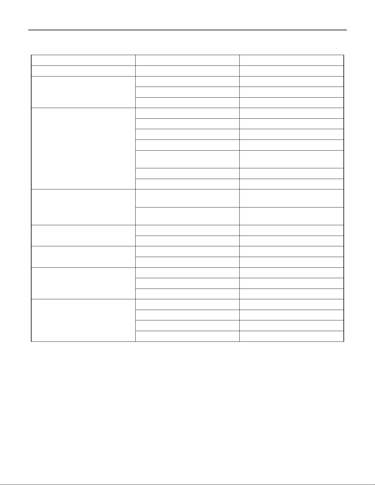
Excessive black exhaust smoke
Condition Possible Cause Correction
Bad injection timing Engine control system malfunction System diagnosis
Bad fuel injector condition
Insufficient compression pressure
Fuel condition
control system
Carbon deposit at nozzle tip Clean fuel injector assembly
Sticking nozzle Replace fuel injector assembly
Engine control system malfunction System diagnosis
Excessive valve clearance Adjust clearance
Sticking valve stem (valve open) Repair or replace valve
Damaged valve spring Replace spring
Valve seat abrasion Repair valve seat
Compression leakage due to
damaged piston ring
Damaged gasket Replace gasket
Piston scoring Replace piston
Water in fuel Drain existing fuel and replace with
Poor fuel quality Drain existing fuel and replace with
Clogged intake pipes Clean or replace pipes Poor engine aspiration
Clogged air cleaner element Clean or replace element
Defective sensor Replace sensor Malfunction detected by engine
Engine control system malfunction System diagnosis
Replace piston ring
new fuel
new fuel
EGR valve and/or intake throttle
valve malfunction
Turbocharger malfunction
Intake throttle valve sticking Repair or replace valve
EGR valve sticking Repair or replace valve
Engine control system malfunction System diagnosis
Damaged turbocharger blade Replace turbocharger
Rough turbocharger shaft rotation Replace turbocharger
Oil leakage from oil seal Replace turbocharger
Broken actuator Replace turbocharger
Page 12
6A-10 ENGINE MECHANICAL (4JJ1)
Excessive white exhaust smoke
Condition Possible Cause Correction
Bad injection timing Engine control system malfunction System diagnosis
Malfunction detected by engine
control system
Insufficient compression pressure
Fuel condition Water in fuel Drain existing fuel and replace with
Excessive oil consumption
Engine knocking
Defective sensor Replace sensor
Control unit malfunction Replace unit
Engine control system malfunction System diagnosis
Excessive valve clearance Adjust clearance
Sticking valve stem (valve open) Repair or replace valve
Damaged valve spring Replace spring
Valve seat abrasion Repair valve seat
Compression leakage due to
damaged piston ring
Damaged gasket Replace gasket
Piston scoring Replace piston
Worn or damaged piston ring(s) Replace ring(s)
Defective valve stem oil seal Replace oil seal
Defective turbocharger oil seal Replace turbocharger
Clogged turbocharger oil return
pipe
Replace piston ring
new fuel
Repair pipe
Condition Possible Cause Correction
Bad timing Engine control system malfunction System diagnosis
Malfunction detected by engine
control system
Fuel condition Poor quality fuel Drain existing fuel and replace with
Poor engine aspiration
Defective sensor Replace sensor
Control unit malfunction Replace unit
Engine control system malfunction System diagnosis
new fuel
Clogged air cleaner element Clean or replace element
Clogged intake pipes Clean or replace pipes
Engine control system malfunction System diagnosis
Foreign material in cylinders Engine overhaul Engine break-down
Scored pistons and/or bearings Replace pistons and/or bearings
Page 13
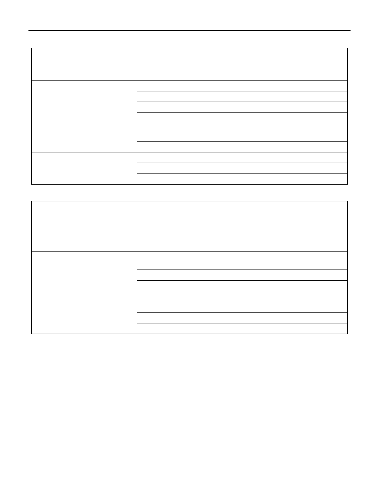
Abnormal engine rotation
Condition Possible Cause Correction
ENGINE MECHANICAL (4JJ1) 6A-11
Defective control unit Replace unit Engine speed cannot be increased
Engine control system malfunction System diagnosis
Engine speed unstable
Turbocharger malfunction
Abnormal battery charging
Condition Possible Cause Correction
No charging
Insufficient charging
Defective control unit Replace unit
Engine control system malfunction System diagnosis
Clogged fuel filter element Replace element
Defective fuel injector(s) Replace fuel injector assembly
Water in fuel Drain existing fuel and replace with
new fuel
Air in fuel system Bleed air from fuel system
Damaged turbocharger fan Replace turbocharger
Rough turbocharger shaft rotation Replace turbocharger
Broken actuator Replace turbocharger
Open or shorted wiring and/or
connectors
Defective generator Repair or replace generator
Defective battery Replace battery
Open or shorted wiring and/or
connectors
Repair or replace wiring and/or
connectors
Repair or replace wiring and/or
connectors
Excessive charging
Defective generator Repair or replace generator
Loose generator drive belt Adjust belt tension or replace belt
Defective battery Replace battery
Shorted wiring Repair or replace wiring
Defective generator Repair or replace generator
Defective battery Replace battery
Page 14
6A-12 ENGINE MECHANICAL (4JJ1)
Turbocharger Troubleshooting
Condition Possible Cause Correction
Engine has less than normal power
Blue exhaust smoke
Air leakage from intake pipe rubber
hose
Air leakage from intake cover Repair intake cover
Clogged intercooler cooling section Clean cooling section
Clogged air cleaner element Clean or replace element
Intake throttle valve stuck Repair or replace throttle valve
Turbine and housing contact
(Interference)
Excessive carbon deposit near
turbine exhaust port that interferes
with turbine
Rough turbine shaft rotation Repair or replace turbine shaft
Damaged turbine blade Repair or replace turbine blade
Oil leakage from turbocharger oil
seal
Clogged turbocharger oil return
pipe
Clogged center housing oil
passages
Repair rubber hose
Replace turbine and/or housing
Clean or repair exhaust port and/or
turbine
Repair or replace oil seal
Repair pipe
Repair or replace center housing
Noisy turbocharger operation
Excessive rotating part wear
Engine oil deterioration Change engine oil
Gas leakage from intake or
exhaust system
Turbine and housing contact
(Interference)
Damaged turbine blade Replace turbine blade
Turbine shaft bearing abrasion or
scoring
Engine oil deterioration Change engine oil
Clogged turbocharger oil feed pipe Repair pipe
Low engine oil pressure Repair
Repair intake or exhaust system
Repair or replace turbine and/or
housing
Repair or replace bearing
Page 15
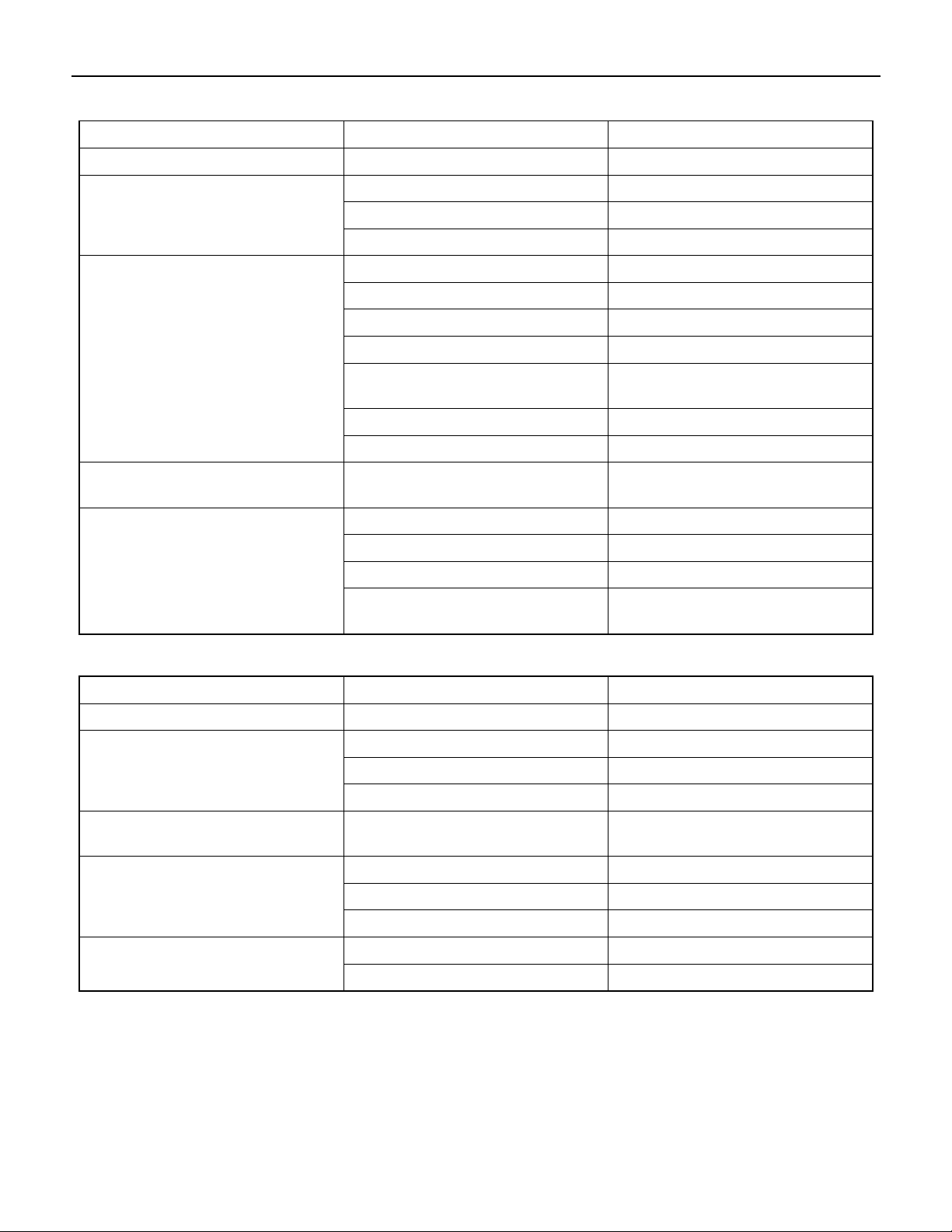
ENGINE MECHANICAL (4JJ1) 6A-13
Main Data and Specifications
Item Engine model 4JJ1
Type Diesel/4-cycle/water cooling-type in-line DOHC
Combustion chamber type Direct injection type
Cylinder liner type Liner less
Number of cylinders -cylinder
bore × strokes
Displacement cc (cu.in) 2999 (183)
Compression ratio 17.5
Compression pressure MPa (psi)/rpm 3 (435)/200
Idling speed rpm 700 ± 25
Valve clearance Intake 0.15 (0.006) (cold)
mm (in) Exhaust 0.15 (0.006) (cold)
Ignition type Compressed ignition
Injection order 1 - 3 - 4 - 2
Lubricating system
Lubricating type Pressure delivery type
Oil pump type Gear type
Volume of lubricating oil L (qts) 8.0 (8.5)
Oil filter type Full flow filter (cartridge type)
Oil cooling type Built-in-type, water cooling
mm (in) 4-95.4(3.76) × 104.9(4.13)
Cooling system
Cooling type Water cooling type
Radiator type Corrugated fin (pressure type)
Water pump type Centrifugal, belt drive type
Thermostat type Wax-type units
Thermostat valve-opening temperature °C (°F) 85 (185)
Volume of coolant L (qts) M/T8.7 (9.2) A/T 8.6 (9.1) (incl. radiator)
Fuel system
Injection pump type Fuel supply pump fuel rail type
Fuel injector type Electronic control injector
6-hole
Fuel pump type Into the fuel tank type
Charging system
Generator type AC type
Power output V-A 12 - 110
Page 16
6A-14 ENGINE MECHANICAL (4JJ1)
Item Engine model 4JJ1
Regulator type IC
Starting system Engage magnet type
Starter type Reduction type
Power output V-kW 12 – 2.3
Preheat system type Glow plug
Glow plug standard voltage/electric current V-A 12 - 3.5
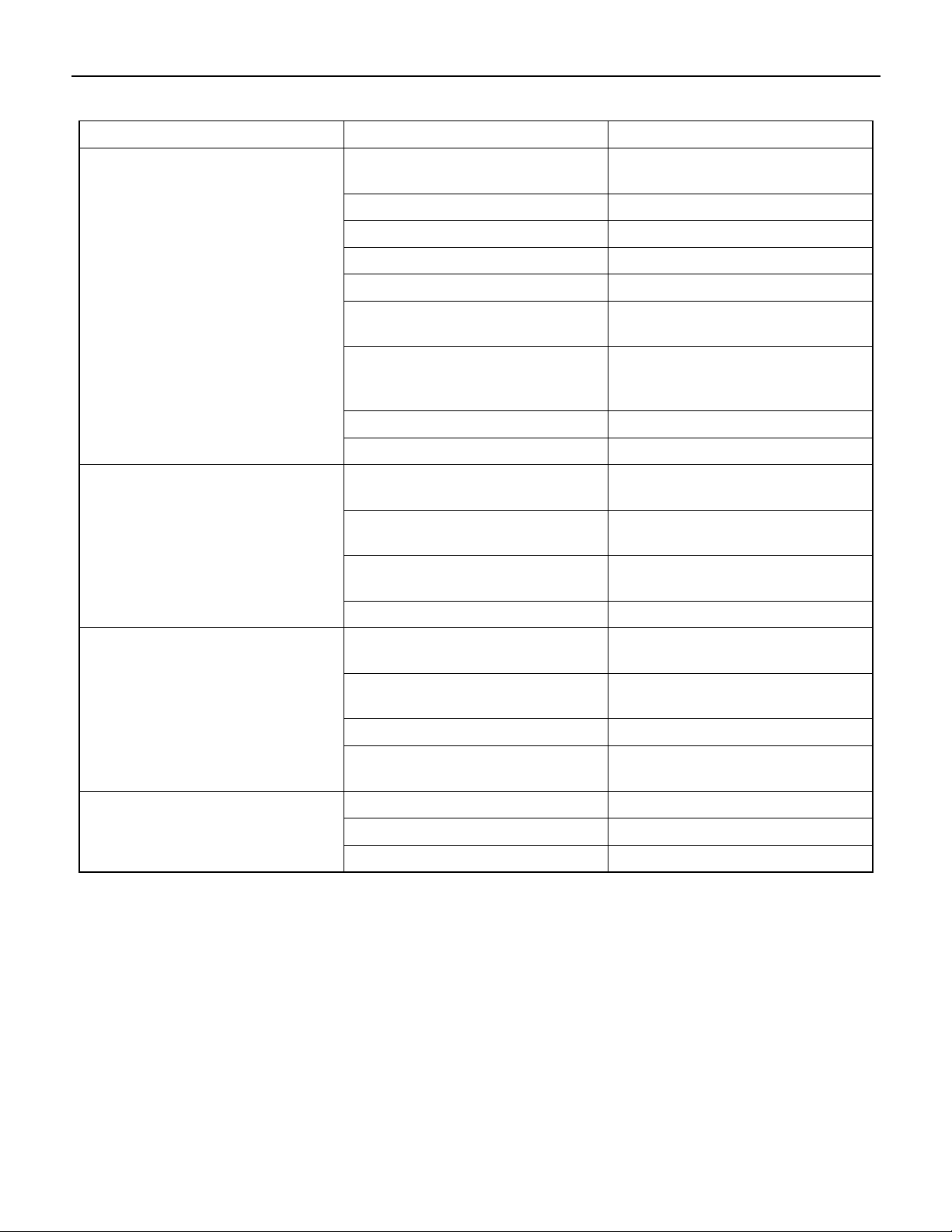
Special Tools
ILLUSTRATION
PART NO.
PART NAME
5-8840-2822-0
Valve clearance
adjust nut wrench
5-8840-2675-0
Compression gauge
5-8840-2815-0
Compression gauge
adapter
Page 17
Engine Assembly
r
ENGINE MECHANICAL (4JJ1) 6A-15
Removal
1. Disconnect the negative battery cable.
2. Remove the engine hood.
3. Drain the coolant.
4. Remove the starter motor.
5. Remove the transmission assembly.
Refer to removal procedure for “TRANSMISSION”
in this manual.
6. Disconnect the ECM harness connector.
7. Remove the ECM.
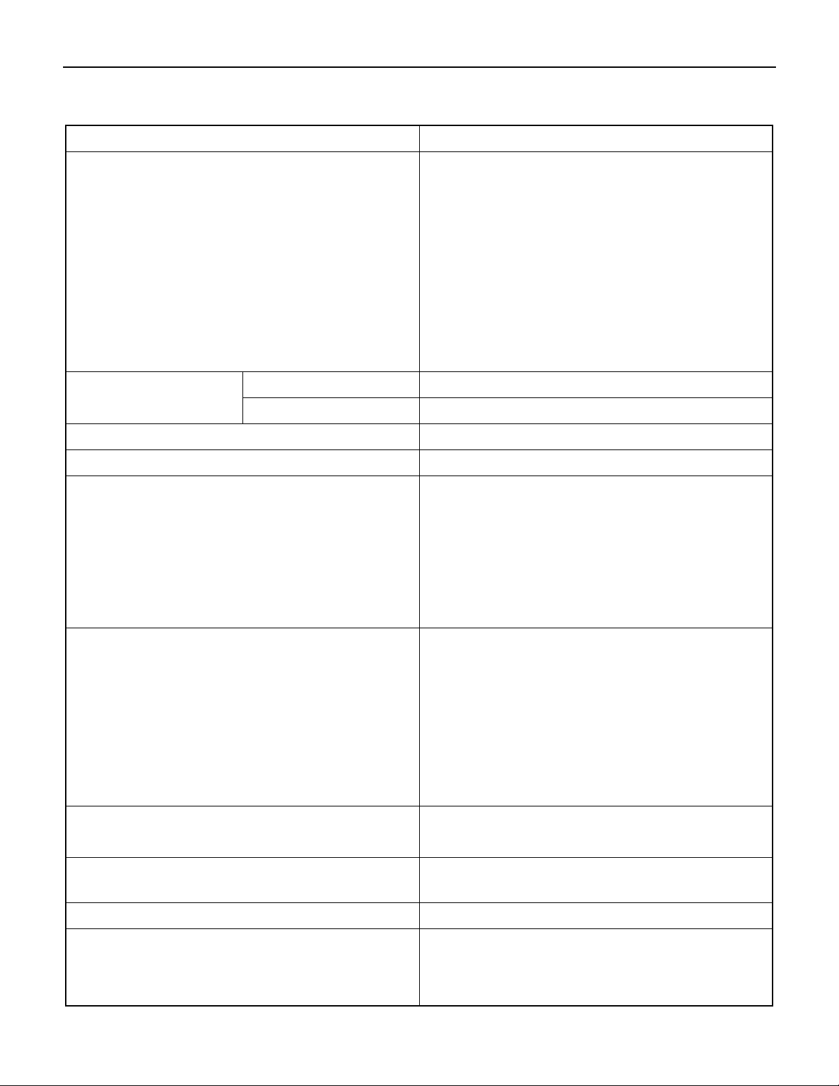
8. Remove the air cleaner.
• Disconnect the MAF sensor harness connector.
• Remove the intake pipe with the lid of ai
cleaner box.
• Remove the air cleaner box.
RTW86ASH001601
Legend
1. Clip
2. Clip
10. Remove the intake hose (intercooler - intake
throttle).
11. Remove the intake hose (turbocharger intercooler).
Remove the harness connector.
Legend
1. ECM Harness Connector
2. ECM
3. Air Cleaner Box
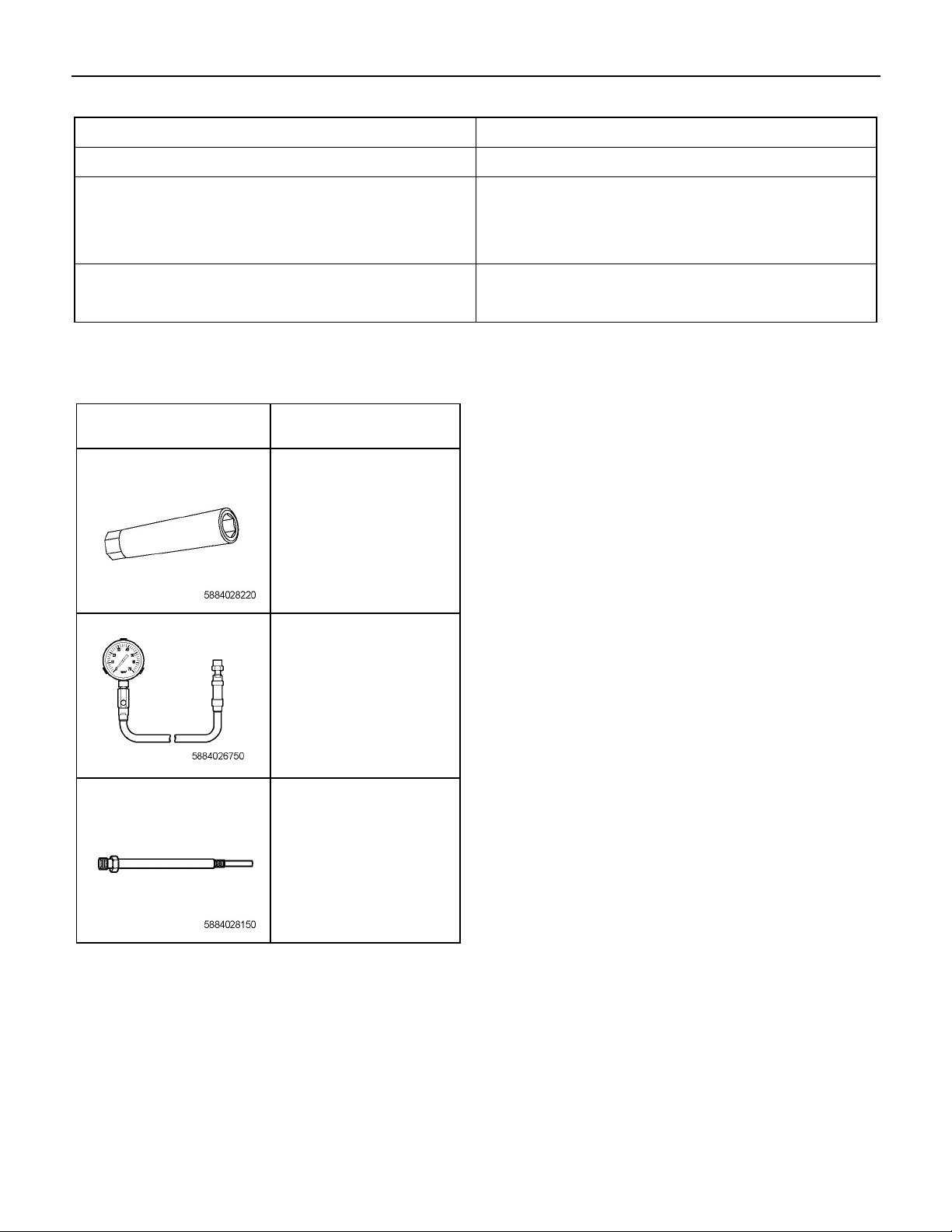
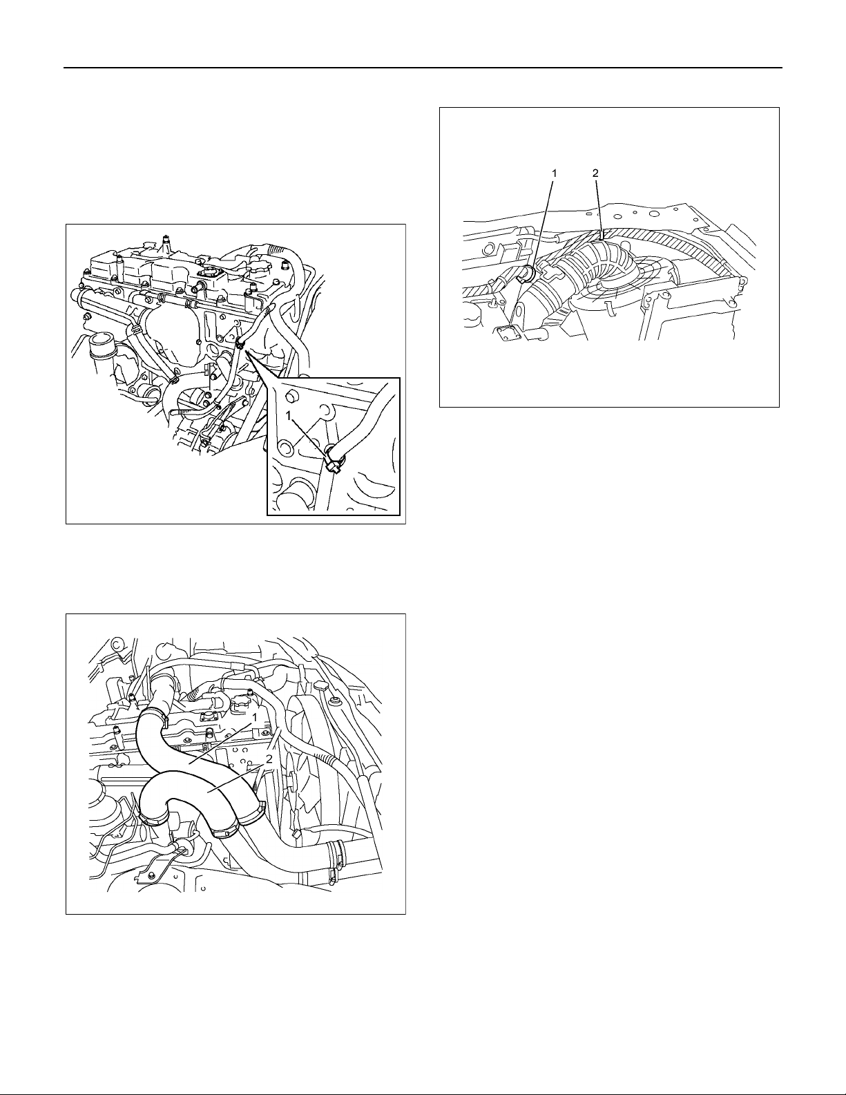
9. Remove the clip (1) and clip (2)
RTW56ASH003901
RTW56ASH004001
Legend
1. Intake Hose (intercooler - intake throttle)
2. Intake Hose (turbocharger - intercooler)
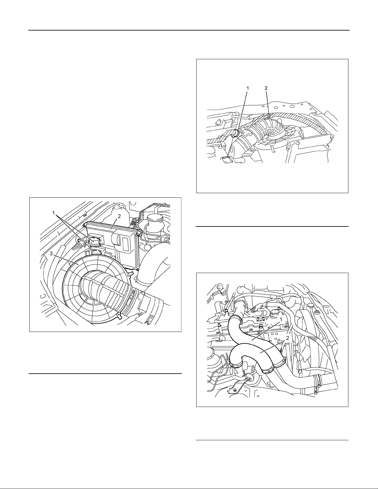
12. Remove the radiator upper hose.
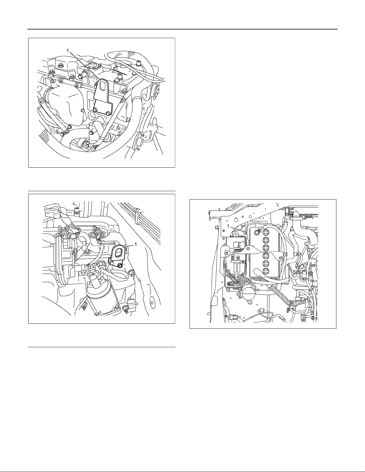
13. Remove the engine harness clip (1).
Page 18
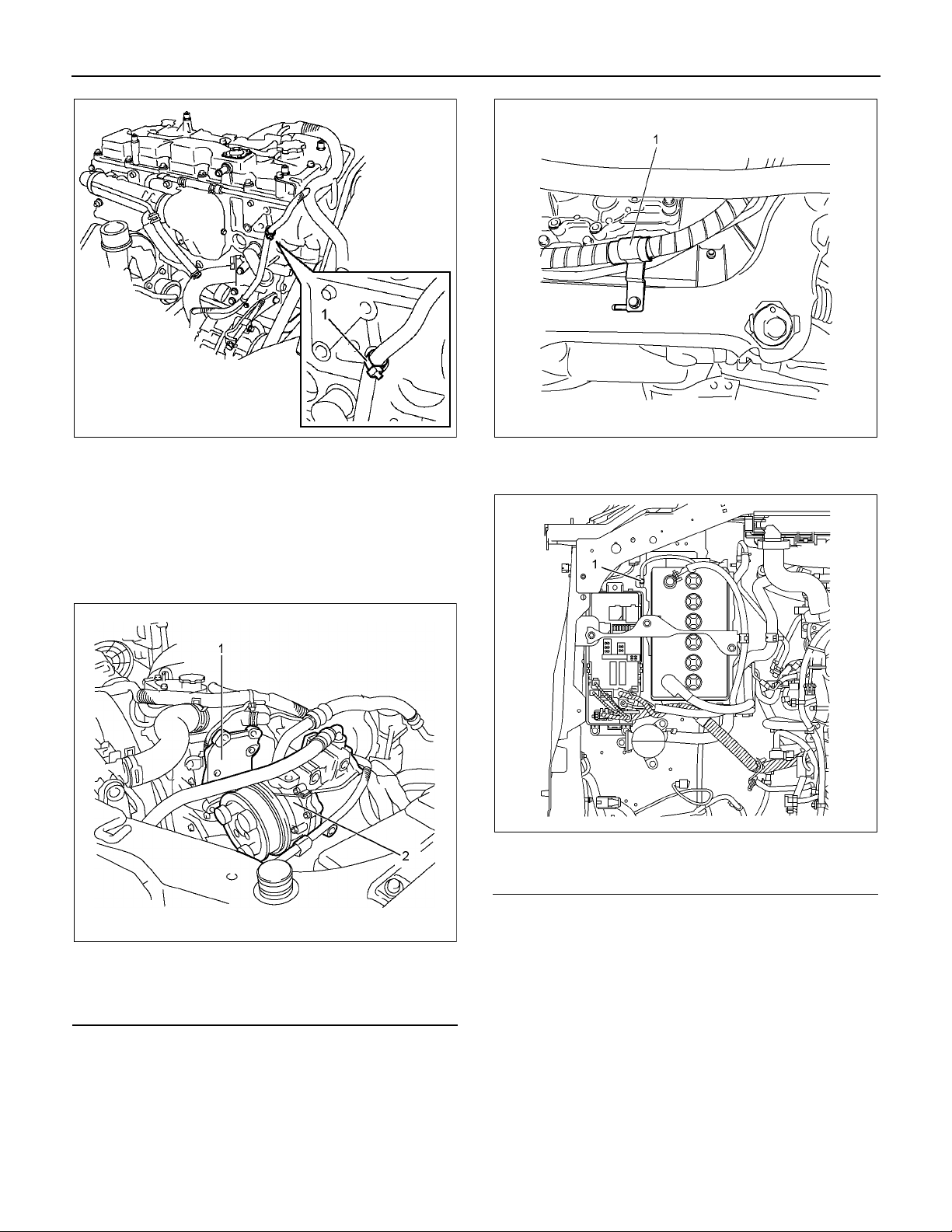
6A-16 ENGINE MECHANICAL (4JJ1)
RTW76ASH001401
14. Remove the breather hose and lower hose of the
radiator.
15. Remove the fan guide.
16. Remove the drive belt.
17. Remove the fan assembly.
18. Remove the radiator.
19. Remove the A/C compressor.
LTW56ASH000101
21. Remove the harness of engine, battery and earth
(1).
Legend
1. A/C Compressor Bracket
2. A/C Compressor
• Disconnect the connector.
• Disconnect the A/C generator harness.
• Disconnect the terminal B cable and harness
connector from the generator.
20. Remove the power steering pump.
• Remove the bracket of power steering oil hose
(1).
RTW76ASH000701
RTW86ASH002001
Legend
1. Earth
22. Remove the connector of the shift on the fly (4×4).
23. Remove the vacuum hose of brake master-vac.
24. Remove the front exhaust pipe.
25. Disconnect the fuel hose on the feed and return
sides.
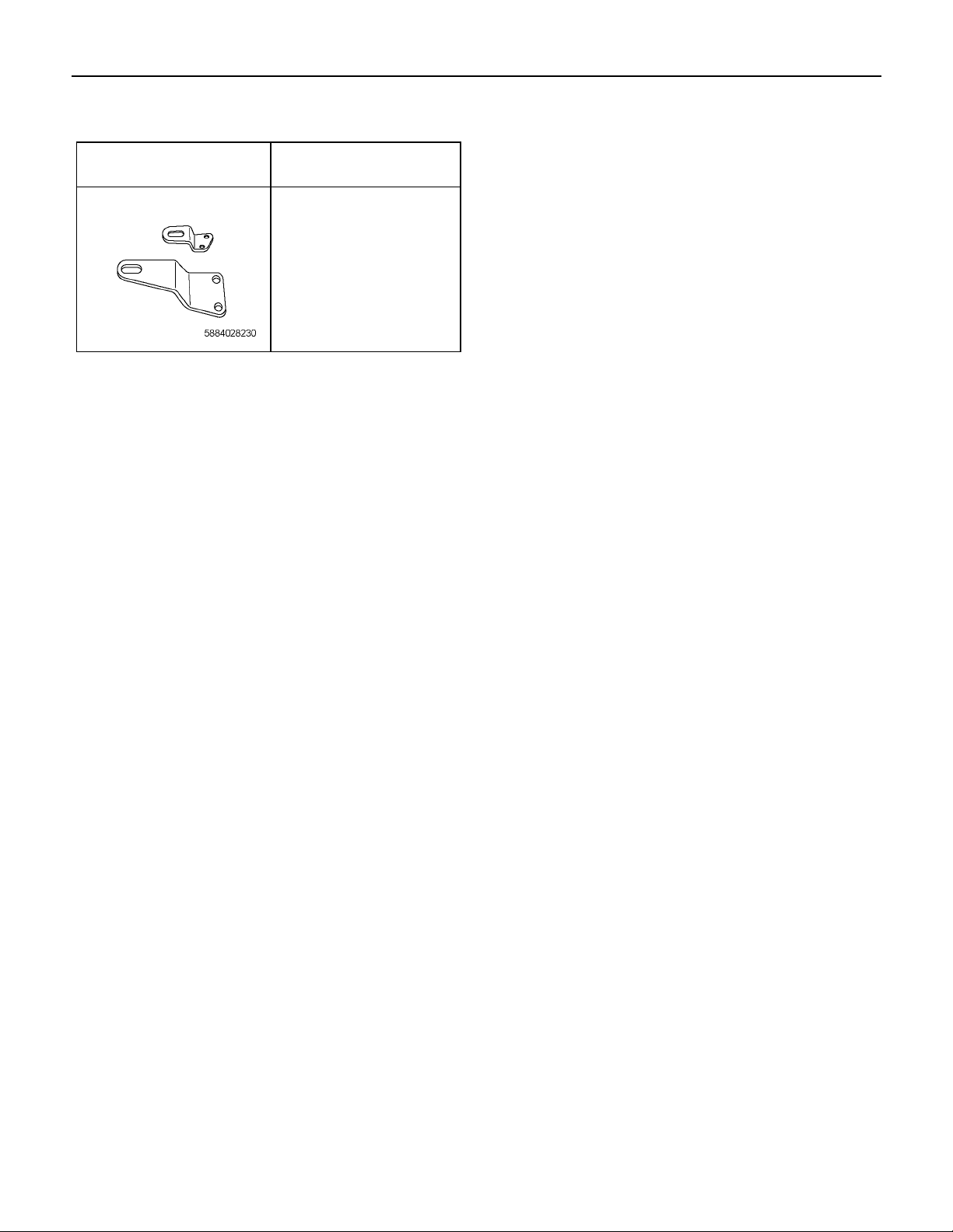
26. Install the engine hanger (special tool 5-88402823-0).
Page 19
ENGINE MECHANICAL (4JJ1) 6A-17
Legend
1. Engine Hanger (Front Side)
RTW56ASH004301
1. Install the engine assembly.
• Hang wire on the engine hanger and hoist to lift up
the engine.
• Operate a hoist slowly to move the engine to the
place where it is to be installed.
• Make the transmission side lower and operate a
hoist slowly, pulling it backward to the engine.
2. Install the engine mount.
Tightening torque: 48 N⋅⋅⋅⋅m (4.9kg⋅⋅⋅⋅m / 35 lb ft)
3. Remove the engine hanger.
4. Install the catalytic converter.
Tightening torque: 27 N⋅⋅⋅⋅m (2.8kg⋅⋅⋅⋅m / 20 lb ft)
5. Install the front exhaust pipe.
Tightening torque: 67 N⋅⋅⋅⋅m (6.8kg⋅⋅⋅⋅m / 49 lb ft)
6. Install the fuel hose on the feed and return sides.
7. Install the vacuum hose of brake master-vac.
8. Install the connector of the shift on the fly (4×4).
9. Install the harness of engine, battery and earth (1).
RTW56ASH004401
Legend
1. Engine Hanger (Rear Side)
27. Hang wire on the engine hanger and hoist to lift
up the engine slightly.
28. Remove the engine mount.
• Remove the fastening bolts for the engine mount
on the engine side.
29. Remove the engine assembly.
• Hoist the engine slightly to provide space to
remove the catalytic converter.
Installation
Notice:
Be absolutely sure that each harness is reconnected to
its original position.
RTW86ASH002001
10.Install the power steering pump.
Tightening torque: 25 N⋅⋅⋅⋅m (2.5kg⋅⋅⋅⋅m / 18 lb ft)
• Install the bracket of power steering oil hose.
11.Install the A/C compressor.
Tightening torque: 25 N⋅⋅⋅⋅m (2.5kg⋅⋅⋅⋅m / 18 lb ft)
• Install the connector.
12.Install the A/C generator harness.
• Install the terminal B cable and the harness
connector to the generator.
13.Install the radiator.
Tightening torque: 25 N⋅⋅⋅⋅m (2.5kg⋅⋅⋅⋅m / 18 lb ft)
14.Install the fan assembly.
Tightening torque: 8 N⋅⋅⋅⋅m (0.8kg⋅⋅⋅⋅m / 69 lb in)
Page 20
6A-18 ENGINE MECHANICAL (4JJ1)
r
r
15.Install the drive belt.
Refer to removal procedure for “DRIVE BELT” in
this manual.
16.Install the fan guide.
17.Install the breather hose and lower hose of the
radiator.
18.Install the engine harness clip (1).
RTW76ASH001401
19.Install the radiator upper hose.
20.Install the intake hose (turbocharger -intercooler).
• Install the harness connector.
21.Install the intake hose (intercooler - intake throttle).
23. Install the clip (1) and clip (2)
RTW86ASH001601
24.Install the ECM.
25.Connect the ECM harness connector.
26.Install the transmission assembly.
Refer to installation procedure fo
“TRANSMISSION”.
27.Install the starter motor.
Tightening torque: 94 N⋅⋅⋅⋅m (9.6kg⋅⋅⋅⋅m / 69 lb ft)
28.Replenish the coolant.
29.Install the engine hood.
Tightening torque: 10 N⋅⋅⋅⋅m (1.0kg⋅⋅⋅⋅m / 87 lb in)
30.Connect the negative battery cable.
RTW56ASH004001
22.Install the air cleaner.
• Install the intake pipe with the lid of air cleane
box.
• Install the air cleaner box.
• Connect the MAF sensor harness connector.
Page 21
Special Tools
ENGINE MECHANICAL (4JJ1) 6A-19
ILLUSTRATION
PART NO.
PART NAME
5-8840-2823-0
Engine hanger
Page 22
6A-20 ENGINE MECHANICAL (4JJ1)
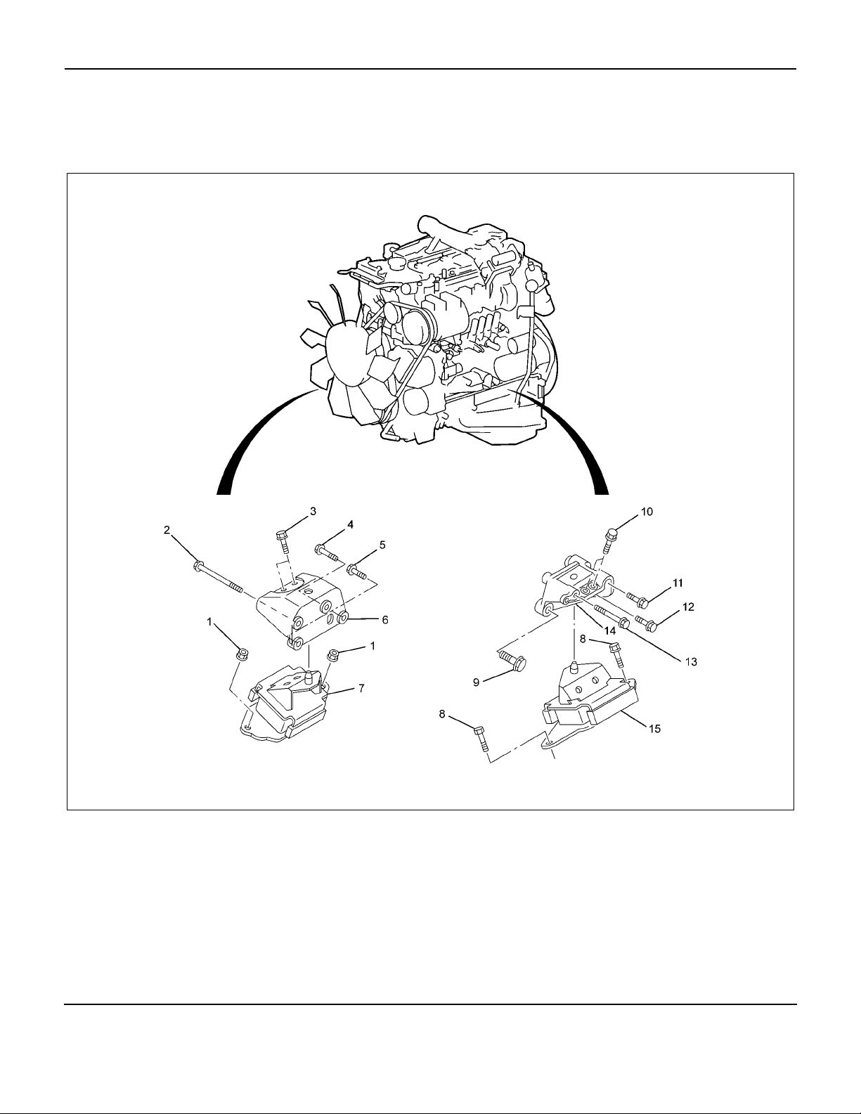
Components
Engine Mount
Legend
1. Nut
2. Bolt (L = 80 mm / 3.15 in)
3. Bolt (L = 30 mm / 1.18 in)
4. Bolt (L = 25 mm / 0.98 in)
5. Bolt (L = 30 mm / 1.18 in)
6. Engine Foot RH
7. Engine Mount RH
8. Bolt (L = 25 mm / 0.98 in)
9. Bolt (L = 45 mm / 1.77 in)
10. Bolt (L = 30 mm / 1.18 in)
11. Bolt (L = 40 mm / 1.57 in)
12. Bolt (L = 20 mm / 0.79 in)
13. Bolt (L = 100 mm / 3.94 in)
14. Engine Foot LH
15. Engine Mount LH
RTW86ALF000301
Page 23
Removal
ENGINE MECHANICAL (4JJ1) 6A-21
Installation
1. Remove the engine hood.
2. Remove the engine cover.
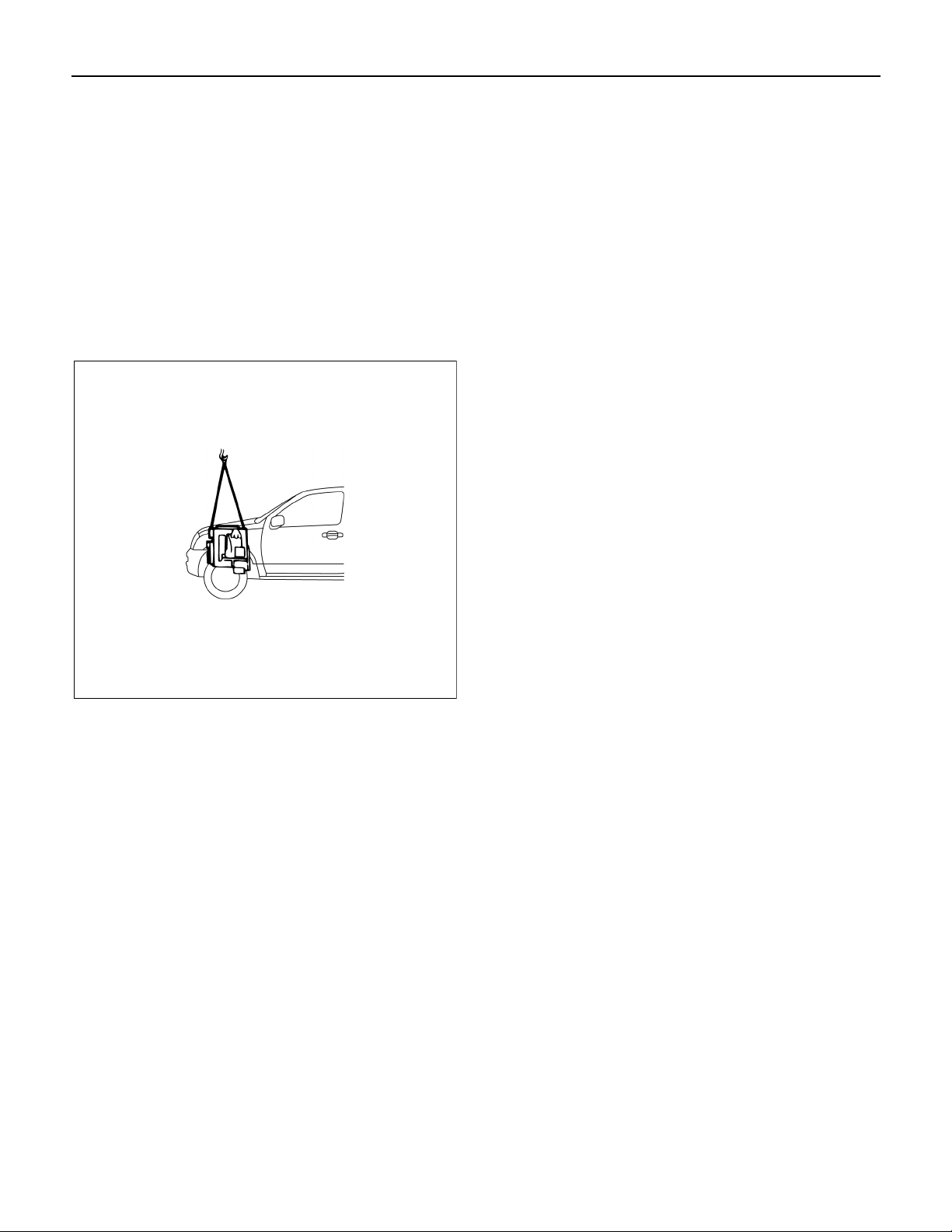
3. Set the hoist and the engine hanger of the special
tool (special tool 5-8840-2823-0).
4. Remove the engine mount.
• Before removing the engine mount, hang the
engine with a hoist.
• Remove the bolts of the engine mount.
• Hoist the engine assembly slightly to remove the
engine mount.
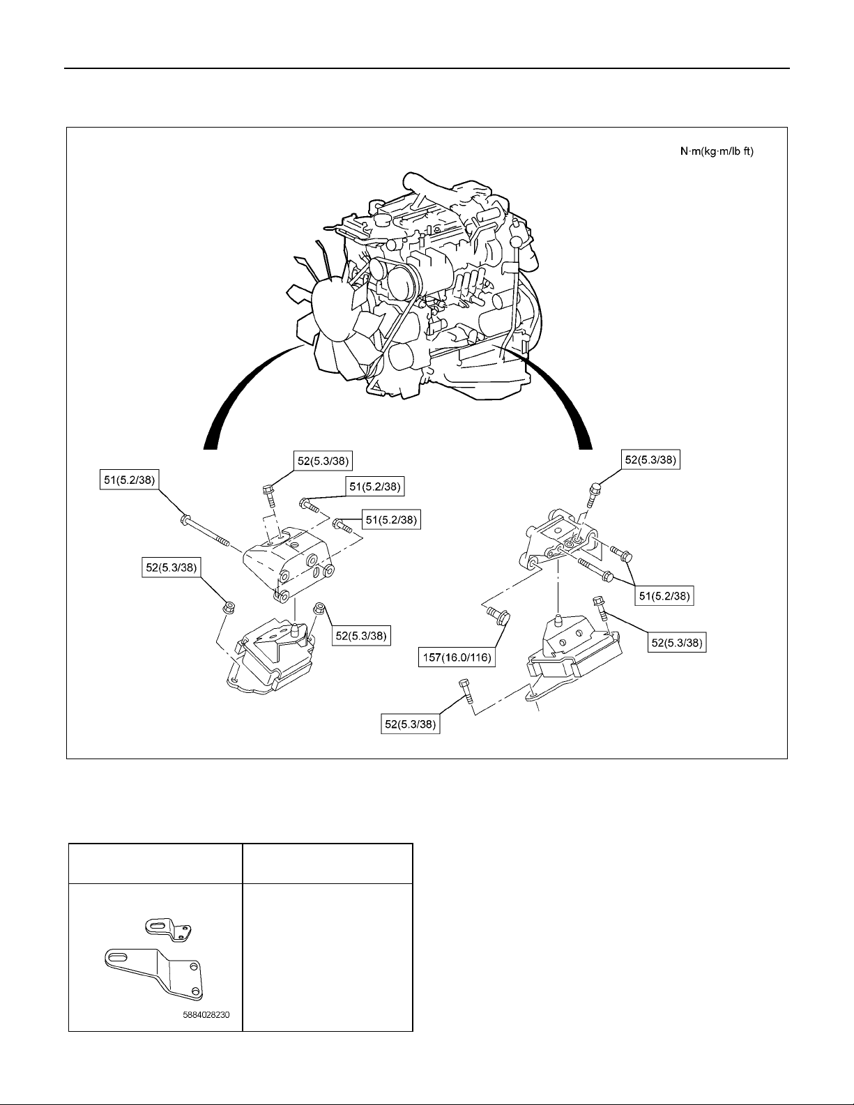
1. Install the engine mount and tighten up with the
specified torque.
Tightening torque: 52 N⋅⋅⋅⋅m (5.3 kg⋅⋅⋅⋅m / 38 lb ft)
2. Remove the engine hanger.
3. Install the engine cover.
4. Install the engine hood.
• Check if nothing is wrong with the engine
mount by starting the engine.
RTW56ASH022401
Page 24
6A-22 ENGINE MECHANICAL (4JJ1)
Torque Specifications
Special Tools
ILLUSTRATION
RTW86ALF000401
PART NO.
PART NAME
5-8840-2823-0
Engine hanger
Page 25
Components
ENGINE MECHANICAL (4JJ1) 6A-23
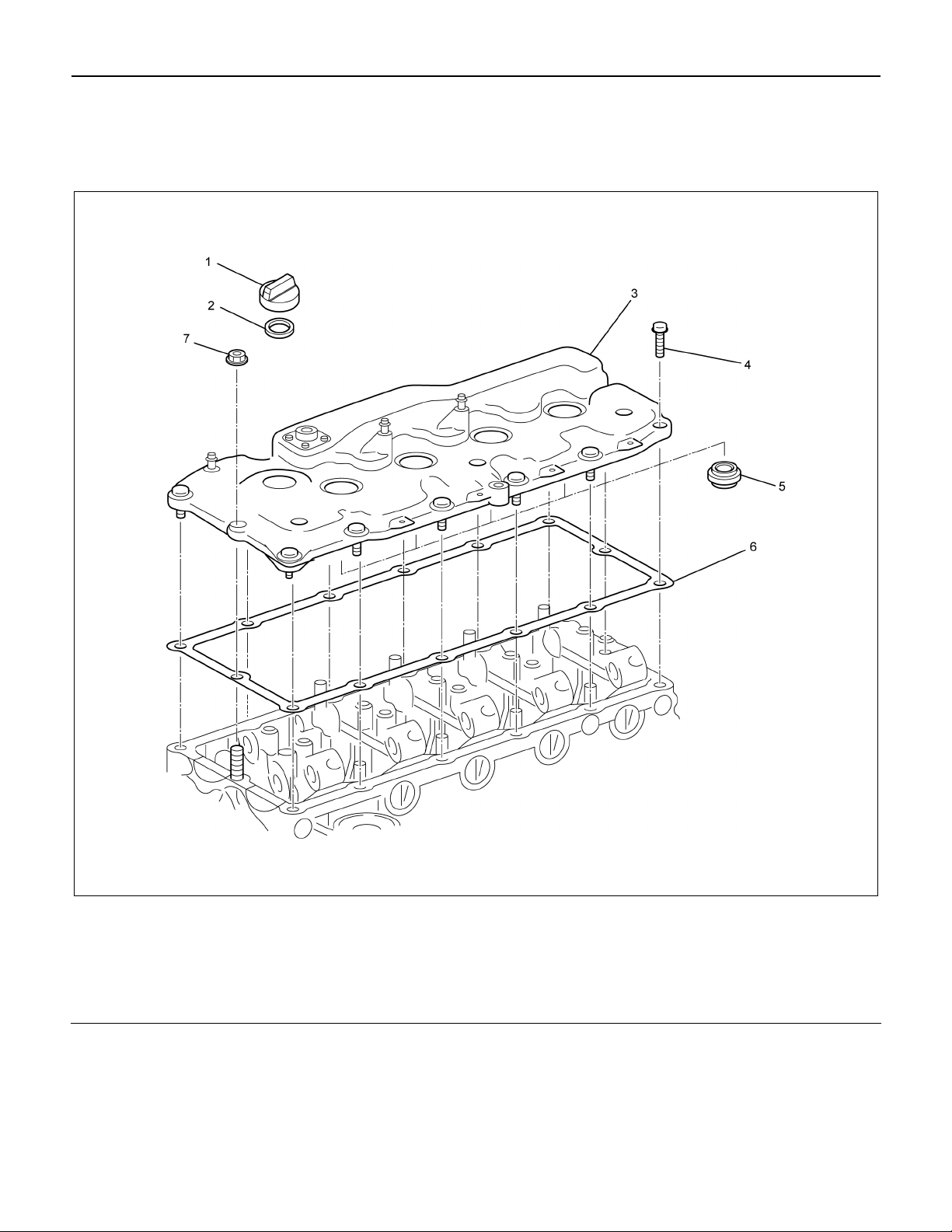
Cylinder Head Cover
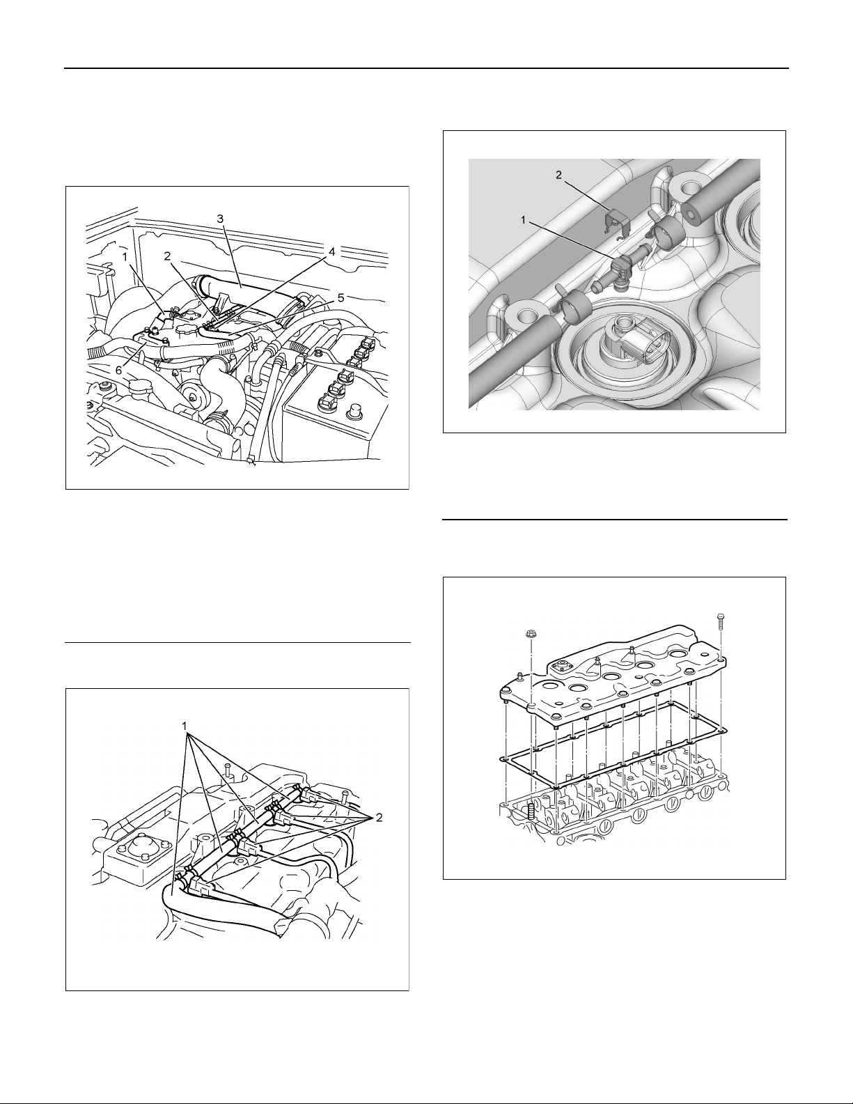
Legend
1. Oil Filler Cap
2. Oil Filler Cap Gasket
3. Cylinder Head Cover
4. Bolt
5. Nozzle Seal Cover
6. Head Cover Gasket
7. Nut
RTWB6ALF000101
Page 26
6A-24 ENGINE MECHANICAL (4JJ1)
Removal
1. Remove the engine cover.
2. Remove the intake air duct (3).
3. Remove the harness bracket (6).
Legend
1. Blow-by Hose
2. Leak-off Hose
3. Intake Air Duct
4. Fuel Injector Connector
5. Leak-off Hose
6. Harness Bracket
RTW56ASH025001
Note: Do not reuse the leak off pipe ASM. (1) and clips
(2).
Legend
1. Leak off pipe ASM.
2. Clip
6. Disconnect the blow-by hose.
7. Remove the cylinder head cover.
LNW86ASH000701
4. Disconnect the fuel injector connectors (2).
5. Remove the fuel leak off hoses (1).
RTW76ASH000101
RTWB6ASH000101
8. Remove the nozzle seal cover from the cylinder
head cover.
• Remove from the lower side of cylinder head
cover.
Page 27
ENGINE MECHANICAL (4JJ1) 6A-25
r
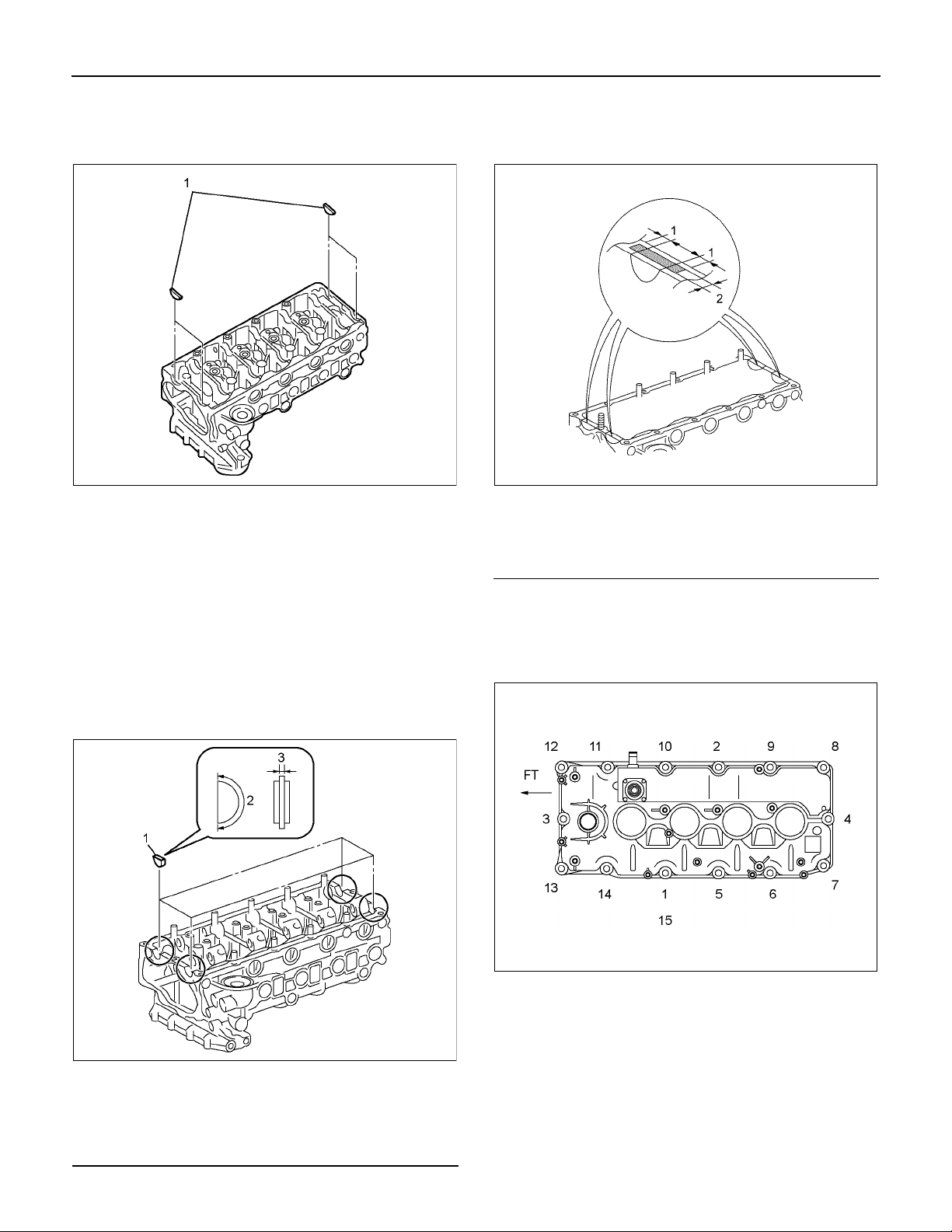
9. Remove the cam end gaskets (1).
• Remove the liquid gasket that has adhered to
cylinder head completely.
Installation
1. Install the nozzle seal cover.
• Insert from the lower side of cylinder head
cover.
• Apply soapy water or engine oil to the surface
of cylinder head cover side.
• Insert the nozzle seal cover as far as it will go.
2. Install the cam end gaskets.
• Apply the liquid gasket (ThreeBond TB-1207B
or equivalent) and mount.
RTW56ASH020501
• Apply attaching cam end gasket.
Apply the liquid gasket (ThreeBond TB-1207B
or equivalent).
Legend
1. 3.0 - 5.0 mm (0.118 - 0.197 in)
2. 3.0 - 5.0 mm (0.118 - 0.197 in)
3. Install the cylinder head cover.
Tightening torque: 10 N⋅⋅⋅⋅m (1.0 kg⋅⋅⋅⋅m / 87 lb in)
• Tighten the nut and bolts in order shown in the
illustration.
RTW56ASH022701
Legend
1. Cam End Gasket
2. Apply The Liquid Gasket
3. 2.0 - 3.0 mm (0.079 - 0.118 in)
RTW56ASH020601
RTW56ASH004801
4. Install the blow-by hose.
5. Install the leak-off hose and the fuel injecto
connector.
6. Install the harness bracket to the cylinder head
cover.
7. Install the intake air duct.
Tightening torque: 25 N⋅⋅⋅⋅m (2.5 kg⋅⋅⋅⋅m / 18 lb ft)
8. Install the engine cover.
Page 28
6A-26 ENGINE MECHANICAL (4JJ1)
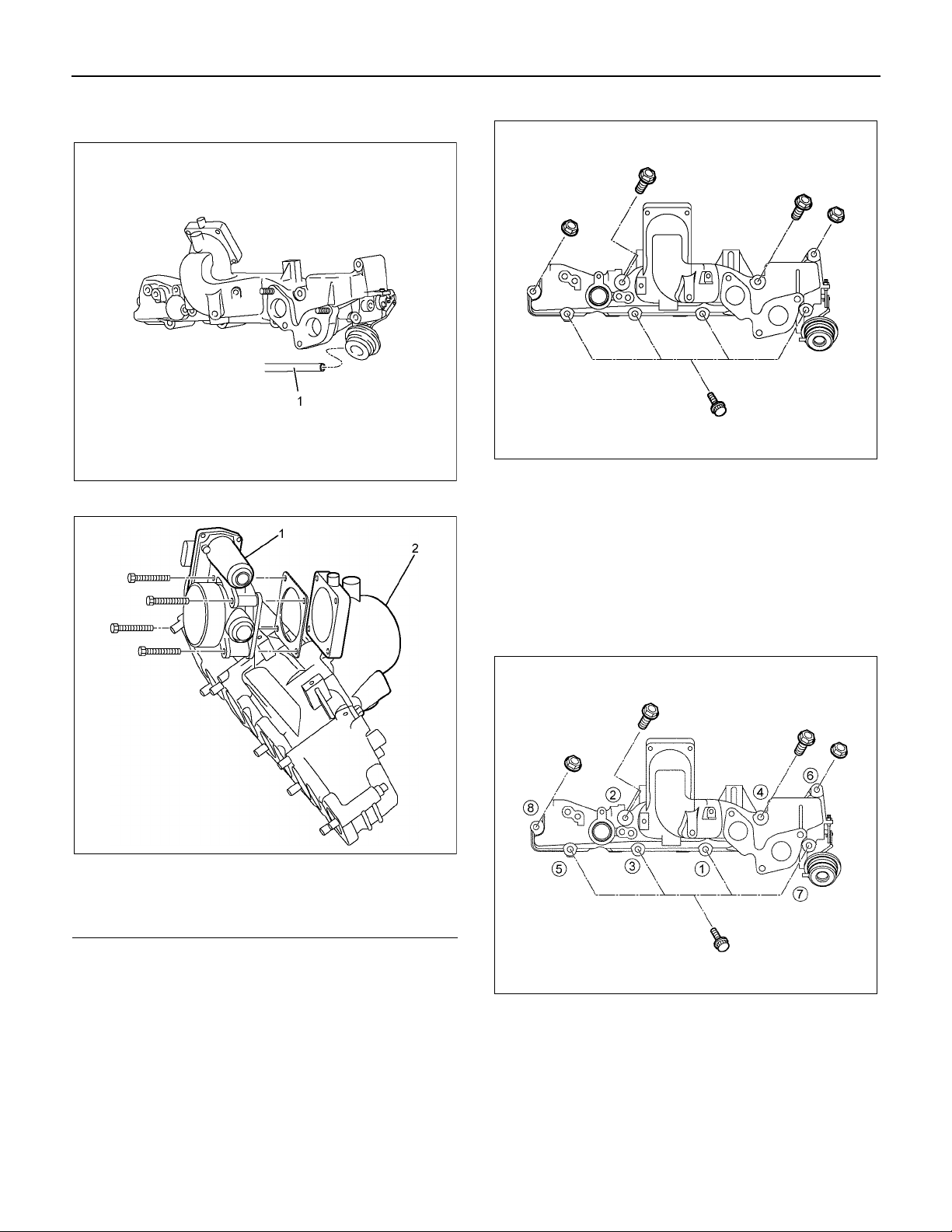
Components
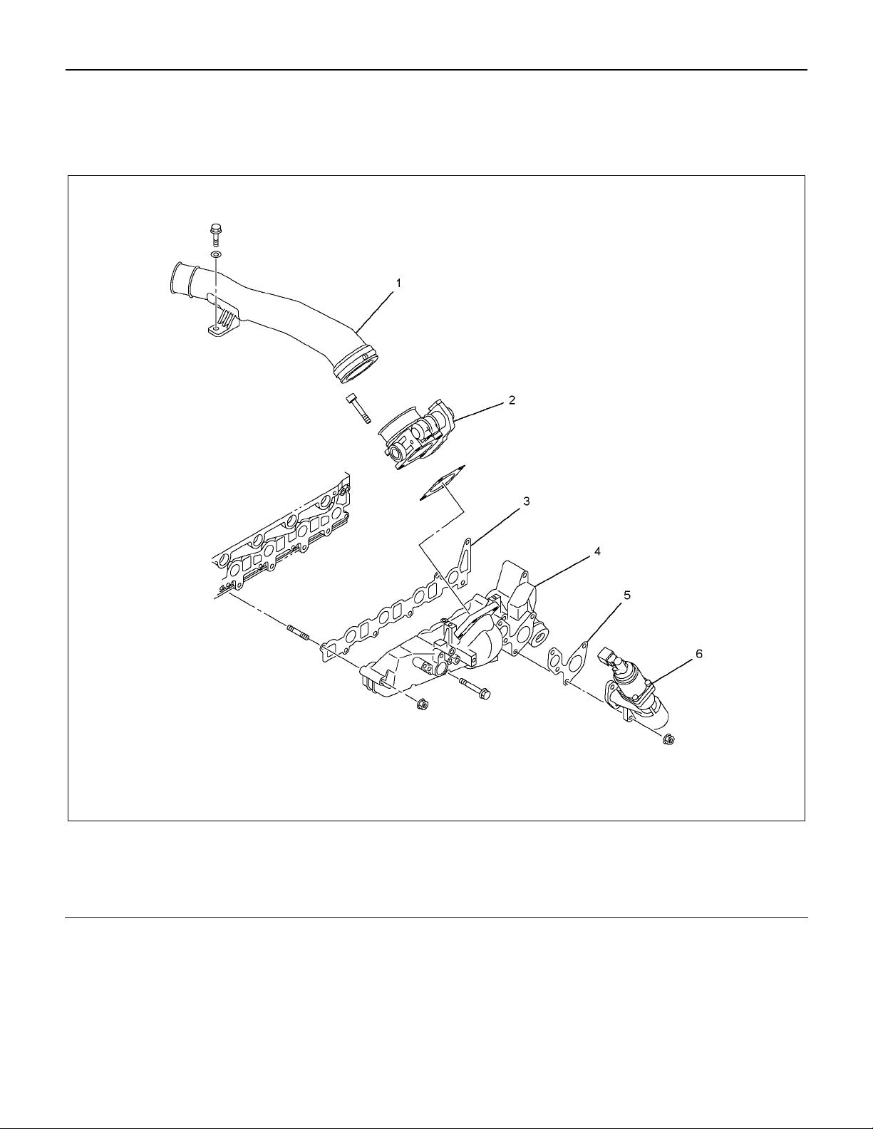
Intake Manifold
Legend
1. Intake Duct
2. Throttle Assembly
3. Intake Manifold Gasket
4. Intake Manifold
5. EGR Valve Assembly Gasket
6. EGR Valve Assembly
RTW76ALF000201
Page 29
ENGINE MECHANICAL (4JJ1) 6A-27
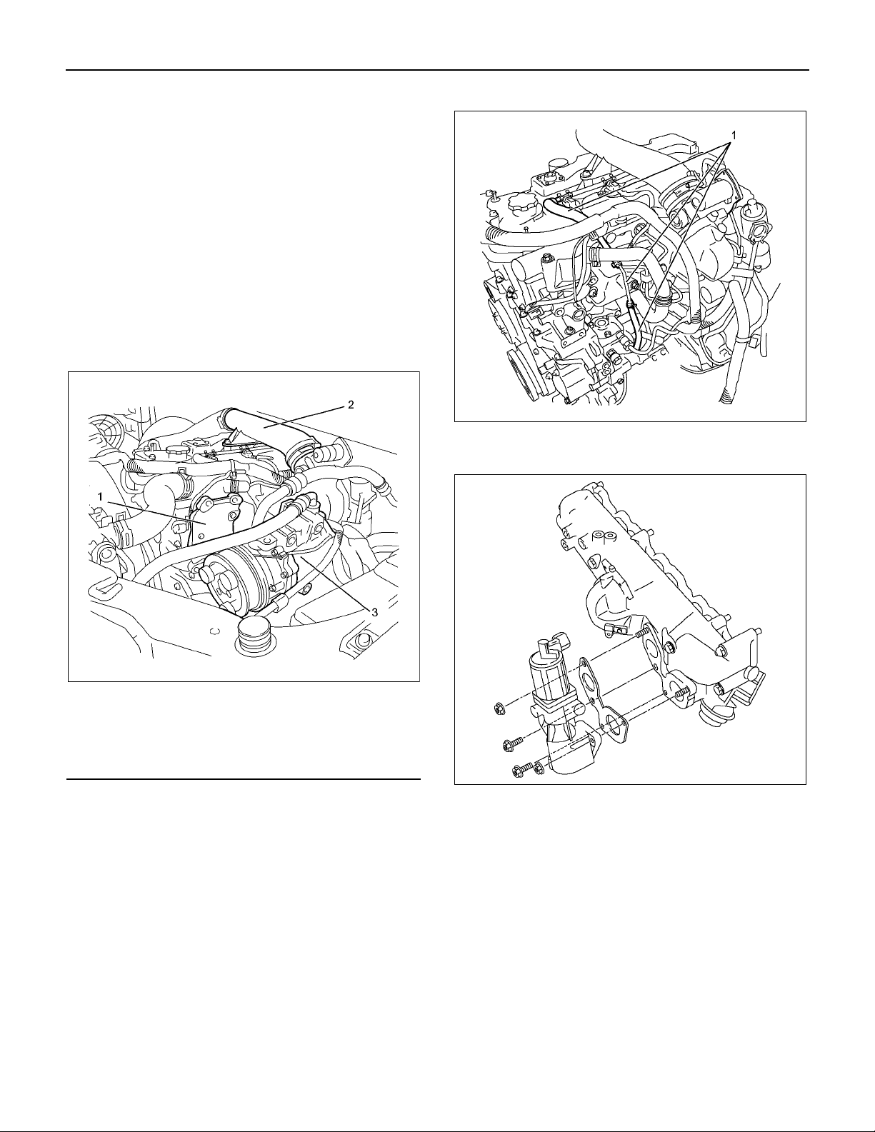
Removal
1. Remove the engine cover.
2. Disconnect the connectors.
• Fuel Injector
• Throttle Assembly
• EGR Valve
• Glow Plug
• Barometric Sensor
• A/C Compressor Connector
3. Remove the A/C belt.
4. Remove the A/C compressor.
5. Remove the A/C compressor bracket.
6. Remove the intake air duct (Standard output).
7. Remove the injector leak-off hoses (1).
RTW56ASH024301
8. Remove the engine oil level gauge guide tube.
9. Remove the EGR valve.
Legend
1. A/C Compressor Bracket
2. Intake Air Duct
3. A/C Compressor
RTW56ASH024801
RTW66ASH003001
10. Remove the injection pipes.
• Remove sequentially from No.1 cylinder.
Page 30
6A-28 ENGINE MECHANICAL (4JJ1)
r
11. Disconnect the vacuum hose of swirl control valve
(1).
RTW66ASH003101
12. Remove the throttle assembly and gasket.
13. Remove the intake manifold.
14. Remove the intake manifold gasket.
Installation
1. Install the intake manifold gasket.
2. Install the intake manifold.
• Tighten the nuts and bolts in the orde
RTW56ASH018001
described in the drawing.
Legend
1. Throttle Assembly
2. Intake Manifold
RTW56ASH005201
Tightening torque: 25 N⋅⋅⋅⋅m (2.5 kg⋅⋅⋅⋅m / 18 lb ft)
RTW56ASH018001
Page 31

ENGINE MECHANICAL (4JJ1) 6A-29
r
3. Install the throttle assembly and gasket.
• Tighten the bolts to the specified torque.
Tightening torque: 10 N⋅⋅⋅⋅m (1.0 kg⋅⋅⋅⋅m / 87 lb in)
4. Install the vacuum hose of swirl control valve.
5. Install the injection pipe (fuel rail - fuel injector).
• It installs sequentially from No. 4 cylinder.
Tightening torque: 29 N⋅⋅⋅⋅m (3.0 kg⋅⋅⋅⋅m / 22 lb ft)
6. Install the EGR valve.
• Tighten the nuts to the specified torque.
Tightening torque: 27 N⋅⋅⋅⋅m (2.8 kg⋅⋅⋅⋅m / 20 lb ft)
7. Install the engine oil level guide tube.
Tighten the nuts to the specified torque.
Tightening torque: 25 N⋅⋅⋅⋅m (2.5 kg⋅⋅⋅⋅m / 18 lb ft)
8. Connect the connector of other parts.
• Fuel Injector
• Throttle Assembly
• EGR Valve
• Glow Plug
• Barometric Sensor
• A/C Compressor Connector
9. Install the leak-off hoses.
13. Install the A/C belt.
Check the A/C belt tension.
• Depress (2) or (4) the A/C belt mid-portion with
98 N (10 kg / 22 lb) force.
• Measure frequency of the specified section (1)
or (3) using a frequency meter.
A/C Belt tension position (1)
Deflection mm(in) Frequency (Hz)
New 9-12 (0.35-0.47) 159-189
Reuse 12-14 (0.47-0.55) 137-155
A/C Belt tension position (3)
Deflection mm(in) Frequency (Hz)
New 5-7 (0.2-0.28) 256-310
Reuse 7-9 (0.28-0.35) 220-252
RTW86ASH001801
Legend
1. Position
2. Deflection
3. Position
Legend
1. Injector Leek-off Hose
10. Install the intake air duct.
RTW56ASH024301
4. Deflection
5. Compressor
6. Compressor belt
7. Crank pulley
14. Install the engine cover.
Tightening torque: 25 N⋅⋅⋅⋅m (2.5 kg⋅⋅⋅⋅m / 18 lb ft)
11.Install the A/C compressor bracket.
Tightening torque: 25 N⋅⋅⋅⋅m (2.5 kg⋅⋅⋅⋅m / 18 lb ft)
12.Install the A/C compressor and A/C compresso
connector.
Tightening torque: 44 N⋅⋅⋅⋅m (4.5 kg⋅⋅⋅⋅m / 33 lb ft)
Page 32

6A-30 ENGINE MECHANICAL (4JJ1)
Torque Specifications
RTW76AMF000101
Page 33

Components
ENGINE MECHANICAL (4JJ1) 6A-31
Turbocharger and Exhaust Manifold
Legend
1. Turbocharger Assembly
2. Exhaust Manifold
3. Heat Protector
4. Catalyst Converter
5. Oil Feed Pipe
6. Oil Return Pipe
7. Intake Hose for Intercooler and Intake Throttle
8. Intake Duct for Turbocharger and Air Cleaner
9. Intake Hose for Turbocharger and Intercooler
RTW56ALF002101
Page 34

6A-32 ENGINE MECHANICAL (4JJ1)
r
r
Removal
1. Loosen the radiator drain plug to drain coolant.
2. Remove the engine cover.
3. Remove the intake hose from the intercooler and
intake throttle.
4. Remove the intake hose from the turbocharge
and the intercooler.
5. Remove the air intake duct from the turbocharge
and the air cleaner.
6. Remove the EGR cooler.
Refer to “EGR Cooler” in EXHAUST SYSTEM
Section.
7. Remove the oil feed pipe.
8. Remove the oil return pipe.
• Loosen clamps (1) of A/T oil cooler pipe.
Legend
1. Oil Feed Pipe
2. EGR Cooler
3. Water Feed Pipe
4. Water Return Pipe
5. Oil Return Pipe
10. Remove the front exhaust pipe.
9. Remove the water feed and return pipe.
RTW56ASH025101
RTW56ASH018301
Legend
1. Gasket
2. Front Exhaust Pipe (4×2 High Ride Suspention,
4×4)
3. Gasket
4. Front Exhaust Pipe (4×2 Except High Ride
Suspention)
11. Disconnect the front propeller shaft flange (1)
(Front Diff Side, 4×4 only).
RTW56ASH005401
RTW76ASH002301
Page 35

ENGINE MECHANICAL (4JJ1) 6A-33
12. Remove the catalyst converter.
14. Remove the exhaust manifold.
• Remove the 8 nuts from the exhaust manifold.
RTW56ASH005601
RTW56ALH000201
13. Remove the turbocharger from the exhaust
manifold.
RTW56ASH005501
Legend
1. Exhaust Manifold
2. Gasket
3. Turbocharger
Page 36

6A-34 ENGINE MECHANICAL (4JJ1)
r
y
y
Inspection
• Inspection of the exhaust manifold. Inspect the
plane surface of the plane on which the
manifold and the cylinder head are to be
installed.
Manifold installation plane surface mm (in)
Standard 0.3 (0.01) or lower
Limit 0.5 (0.02)
Note:
If the plane surface exceeds the limit, replace it.
Wheel shaft and bearing clearance
Use a dial gauge to measure the clearance between the
wheel shaft and the bearing.
Clearance mm (in)
Standard 0.056 − 0.127 (0.0022 − 0.0050)
Limit 0.14 (0.0055)
LNW21BSH022201
LNW21BSH022301
• Check a crack in the exhaust manifold visually.
Carefully inspect the turbocharger for abrasion and/o
excessive wear. Make any necessary adjustments,
repairs, and/or part replacements.
Wheel shaft axial play
Use a dial gauge to measure the wheel axle shaft pla
when a force of 12 N (1.2 kg / 2.6 lb) is alternatel
applied to both sides of the compressor wheel.
Axial play mm (in)
Standard 0.03 − 0.06 (0.0012 − 0.0024)
Limit 0.09 (0.0035)
Legend
1. Oil Outlet
2. Oil Intake
LNW21BSH022301
Page 37

ENGINE MECHANICAL (4JJ1) 6A-35
A
Waste gate operation
1. Remove the hose from the waste gate actuator.
2. Install the pressure gauge (general tool). Refer to
the illustration.
RTW56ASH005701
Legend
1. Waste Gate Actuator
2. Waste Gate Hose
3. Pressure Gauge (General Tool)
3. Use the pressure gauge pump to apply pressure
(load) to the waste gate actuator (the engine must
be off).
4. Note the pressure at which the control rod moves
2 mm (0.079 in). This pressure must be within the
specified limit.
Control rod pressure range: kPa (mmHg / psi)
109 − 118 (818 − 885 / 16 − 17)
5. Inspect the hose for cracks and other damage.
Replace the hose if necessary.
6. Do not apply a pressure of more than 120 kPa
(900 mmHg) to the waste gate actuator.
Installation
1. Put the gasket in to install the exhaust manifold.
•
ssemble the washers and nuts as shown in
the diagram and temporarily tighten them.
Legend
1. Stud
2. Washer
3. Nut
• Tighten up with the 8 nuts according to the
order given in the figure.
Tightening torque: 52 N⋅⋅⋅⋅m (5.3 kg⋅⋅⋅⋅m / 38 lb ft)
Note:
Do not tighten up too much because it hampers
expansion and contraction due to the heat from the
manifold.
LNW71BSH002001
RTW56ASH005801
Page 38

6A-36 ENGINE MECHANICAL (4JJ1)
f
r
2. Install the gasket and turbocharger to the exhaust
manifold. Tighten the nuts to the specified torque.
Tightening torque: 27 N⋅⋅⋅⋅m (2.8 kg⋅⋅⋅⋅m / 20 lb ft)
RTW56ASH005501
Legend
1. Exhaust Manifold
2. Gasket
3. Turbocharger
RTW56ASH019101
7. Install the water return pipe. Tighten the joint bolt
to the specified torque.
Tightening torque: 54 N⋅⋅⋅⋅m (5.5 kg⋅⋅⋅⋅m / 40 lb ft)
3. Install the catalyst converter.
Tighten the nuts to the specified torque.
Tightening torque: 27 N⋅⋅⋅⋅m (2.8 kg⋅⋅⋅⋅m / 20 lb ft)
4. Connect the front propeller shaft flange (Front Dif
Side, 4×4 only).
5. Install the front exhaust pipe.
Tighten the nuts to the specified torque.
Tightening torque
Exhaust Manifold Side: 67 N
Exhaust Pipe Side: 43 N
⋅⋅⋅⋅
m (6.8 kg
⋅⋅⋅⋅
m (4.4 kg
⋅⋅⋅⋅
m / 49 lb ft)
⋅⋅⋅⋅
m / 32lb ft)
6. Install the water feed pipe to the turbocharger (1).
• Tighten the joint bolts to the specified torque.
Tightening torque: 54 N⋅⋅⋅⋅m (5.5 kg⋅⋅⋅⋅m / 40 lb ft)
• Install the pipe bracket and tighten the bolts to
the specified torque.
Tightening torque: 10 N⋅⋅⋅⋅m (1.0 kg⋅⋅⋅⋅m / 87 lb in)
• Install the rubber hoses between the wate
return pipes and the thermostat housing.
RTW56ASH019001
8. Install the turbocharger oil feed pipe to the top of
the turbocharger. Tighten the joint bolts to the
specified torque.
Tightening torque (Turbo charger side):
22.5 N⋅⋅⋅⋅m (2.3 kg⋅⋅⋅⋅m / 17 lb ft)
Tightening torque (Oil cooler side):
22.5 N⋅⋅⋅⋅m (2.3 kg⋅⋅⋅⋅m / 17 lb ft)
• Install the pipe bracket and tighten the bolts to
the specified torque.
Tightening torque: (Clip)
10 N⋅⋅⋅⋅m (1.0 kg⋅⋅⋅⋅m / 87 lb in)
Page 39

ENGINE MECHANICAL (4JJ1) 6A-37
r
r
Legend
1. Oil Feed Pipe
2. Clip
3. For Dia 8.00 mm (0.31 in)
4. For Dia 10.00 mm (0.39 in)
5. Oil Return Pipe
RTW96ASH000101
9. Tighten the oil return pipe bolts and nuts to the
specified torque.
Tightening torque (Turbocharger side):
10 N⋅⋅⋅⋅m (1.0 kg⋅⋅⋅⋅m / 87 lb in)
Tightening torque (Crank case side):
25 N⋅⋅⋅⋅m (2.5 kg⋅⋅⋅⋅m / 18 lb ft)
10.Install the EGR cooler.
• Refer to “EGR Cooler” in EXHAUST SYSTEM
section.
11. Install the heat protector.
• Refer to “EGR Cooler” in EXHAUST SYSTEM
section.
12. Install the intake hose between the intercooler and
the intake throttle .
13. Install the intake hose between the turbocharge
and the intercooler .
14. Install the intake duct between the turbocharge
and the air cleaner .
Tightening torque: 4 N⋅⋅⋅⋅m (0.4 kg⋅⋅⋅⋅m / 35 lb in)
15.Replenish the coolant.
Page 40

6A-38 ENGINE MECHANICAL (4JJ1)
Torque Specifications
RTW86ALF000701
Page 41

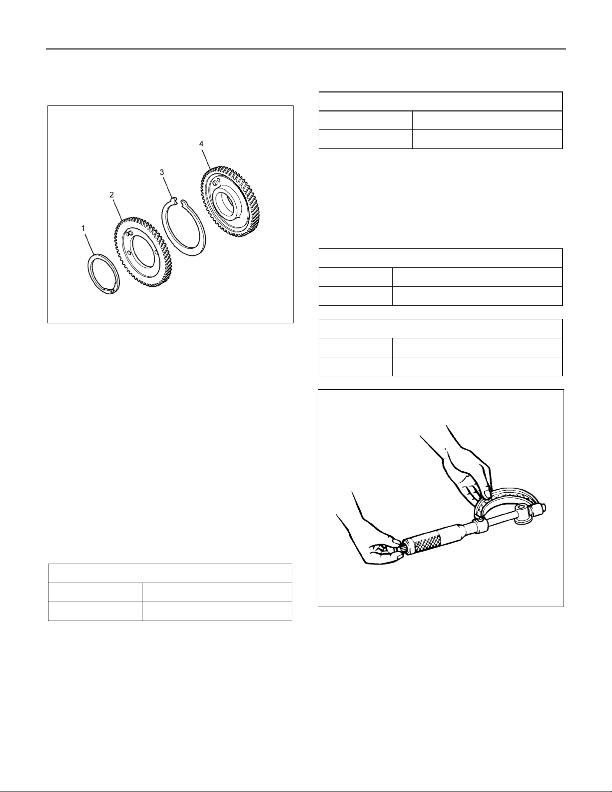
Components
Timing Gear Train
ENGINE MECHANICAL (4JJ1) 6A-39
Legend
1. Oil Pump Gear
2. Crankshaft Gear
3. Idle Gear D
4. Exhaust Camshaft Gear
5. Intake Camshaft Gear
6. Idle Gear D Sprocket
7. Timing Chain
8. Injection Pump Sprocket
9. Injection Pump Gear
10. Idle Gear A
11. Vacuum Pump Gear
12. Power Steering Oil Pump Gear
13. Idle Gear C
RTW56ALF001101
Page 42

6A-40 ENGINE MECHANICAL (4JJ1)
Removal
1. Partially drain the engine coolant.
2. Remove the radiator upper hose.
3. Remove the fan guide.
RTW56FSH000101
4. Remove the cooling fan and fan pulley.
5. Remove the A/C compressor drive belt and fan
belt.
6. Remove the crank pulley.
Note:
Do not reuse the crank pulley bolt.
7. Remove the power steering pump with hose.
RTW56ASH025401
Legend
1. Fan Guide
2. Clips
3. Lower Fan Guide
4. Fan Shroud
RTW46BSH000101
Legend
1. Power Steering Pump
2. Nut
• Disconnect the bracket (1) of power steering oil
hose.
RTW56ASH021101
Page 43

ENGINE MECHANICAL (4JJ1) 6A-41
8. Remove the vacuum pump.
• Remove the vacuum pipe bracket and vacuum
pipe.
• Remove the oil pipe (feed side and return side)
of vacuum pump.
LTW56ASH000101
9. Remove the front cover.
RTWB6ASH001001
10. Install the M6 bolt to the idle gear A.
11. Remove the idle gear A and idle gear A flange, idle
gear A shaft.
RTW56ASH011301
RTWB6ASH000801
Page 44

6A-42 ENGINE MECHANICAL (4JJ1)
f
12. Remove the idle gear C and idle gear C shaft.
RTW56ASH011401
13. Remove the crankshaft gear.
Disassembly
1. Remove the scissor gear assembly.
• Clamp the vise. Insert soft metal protectors
(aluminum) between the vise and component.
Use a pair of snap ring pliers to remove the
scissor gear assembly.
RTW56ASH022001
Legend
1. Snap Ring
2. Sub-gear
3. Spring
4. Idle Gear A
Reassembly
RTW56ASH021501
1. Install the scissor gear assembly.
• Clamp the vise. Insert soft metal protectors
(aluminum) between the vise and component.
Press against the pin on the left side of the idle
gear A spring to make a gap on the right side o
the spring. Push the spring into place.
Page 45
ENGINE MECHANICAL (4JJ1) 6A-43
A
r
r
r
• Align the sub gear pin with the hole in the right
side of the idle gear A spring. Press the subgear into place.
Legend
1. Snap Ring
2. Sub-gear
3. Spring
4. Idle Gear A
• Use a pair of snap ring pliers to snuggly install
the snap ring.
RTW56ASH022001
• If the measurement exceeds the limit, replace
either the idle gear or the thrust collar.
End clearance of the idle gear mm (in)
Standard 0.060 − 0.135 (0.002 − 0.005)
Limit 0.20 (0.008)
• Measure an end clearance of the idle gear
before removing the idle gear B.
3. External diameter of the idle gear shaft.
• Use a micrometer to measure an external
diameter of each idle gear shaft.
• If the measurement exceeds the limit, replace
the shaft.
External diameter of the idle gear A shaft mm (in)
Standard 44.950 − 44.975 (1.7697 − 1.7707)
Limit 44.80 (1.764)
External diameter of the idle gear C shaft mm (in)
Standard 24.959 − 24.980 (0.9826 − 0.9835)
Limit 24.80 (0.976)
Inspection
1. Measurement of idle gear backlash
•
pply a dial gauge on the teeth of the idle gea
to be measured and move the gear to right and
left lightly to read how much the dial gauge
shook (never fail to fix the gear).
• If the measurement exceeds the limit, replace
the idle gear.
Backlash of the idle gear mm (in)
Standard 0.10 − 0.17 (0.004 − 0.007)
Limit 0.30 (0.01)
• Measure backlash of the idle gear before
removing the idle gear A.
2. Measurement of end clearance of the idle gear.
• Insert a thickness gauge between the idle gea
and the thrust collar to measure a clearance.
RTW56ASH021601
4. Clearance between the idle gear and the idle gear
shaft
• Measure an inside diameter of the idle gea
bush to calculate a clearance between the idle
gear and the idle gear shaft.
Page 46

6A-44 ENGINE MECHANICAL (4JJ1)
A
f
A
• If the measurement exceeds the limit, replace
either the idle gear or the shaft.
Clearance between the idle gear A and the shaft
mm (in)
Standard 0.025 − 0.075 (0.0010 − 0.0030)
Limit 0.200 (0.0079)
Clearance between the idle gear C and the shaft
mm (in)
Standard 0.020 − 0.062 (0.0008 − 0.0024)
Limit 0.200 (0.0079)
LNW21BSH003601
pply engine oil to the bolt screw thread and
•
seat, and temporarily tighten together with the
flange (tighten fully in later process).
RTW56ASH011401
3. Install the idle gear A.
4. Tighten sub gear setting bolt.
• Use the M6 bolts and lever to turn sub gear to
right direction until it aligns with the M6 bolt
hole between idle gear A and sub gear.
• Tighten the M6 bolt to a suitable torque to
prevent the sub gear from moving.
Installation
1. Install the crankshaft gear.
2. Install the idle gear C.
•
pply engine oil over the part where the gear o
the idle gear shaft is to be put together.
RTW56ASH011501
Page 47

ENGINE MECHANICAL (4JJ1) 6A-45
A
f
A
• Align the oil hole of the cylinder body (2) with
the oil hole of the idle gear A shaft (3).
• Install the flange so that the front mark (1) face
toward the front.
• Install the idle gear A and idle gear A flange,
idle gear A shaft at the position shown in the
figure.
•
pply engine oil over the part where the gear o
the idle gear shaft is to be put together.
•
pply engine oil to the bolt screw thread and
seat, and temporarily tighten together with the
flange (tighten fully in later process).
• Attach, aligning with the gear crank: idle A and
timing mark.
LNW81BSH000401
RTW56ALH000301
5. Tighten the bolts of idle gear A and idle gear C to
the specified torque.
Tightening torque:
idle gear A 32 N⋅⋅⋅⋅m (3.3 kg⋅⋅⋅⋅m / 24 lb ft)
idle gear C 59 N⋅⋅⋅⋅m (6.0 kg⋅⋅⋅⋅m / 43 lb ft)
RTW56ASH011701
Legend
1. Idle Gear A Bolt
2. Idle Gear C Bolt
Page 48

6A-46 ENGINE MECHANICAL (4JJ1)
f
r
6. Remove the M6 bolt from the idle gear A.
7. Install the gear case cover.
• Apply the liquid gasket (ThreeBond TB-1207B
or equivalent).
Legend
1. Apply the liquid gasket
RTW56ASH020101
8. Install the vacuum pump.
Tightening torque: 25 N⋅⋅⋅⋅m (2.5 kg⋅⋅⋅⋅m / 18 lb ft)
• Install the oil pipe (feed side and return side) o
vacuum pump.
• Install the vacuum pipe bracket and vacuum
pipe.
9. Install the power steering pump.
• Tighten the nuts to the specified torque.
Tightening torque: 25 N⋅⋅⋅⋅m (2.5 kg⋅⋅⋅⋅m / 18 lb ft)
• Connect the bracket (1) of power steering oil
hose.
• Install the gasket in slot of the gear case cover.
• Tighten the bolts to the specified torque.
Tightening torque: 8 N⋅⋅⋅⋅m (0.8 kg⋅⋅⋅⋅m / 69 lb in)
RTW56ASH012101
LTW56ASH000101
10. Install the crank pulley.
• Please use new crank pulley bolt.
• Tighten the bolt to the specified torque.
Tightening torque: 294 N⋅⋅⋅⋅m (30.0 kg⋅⋅⋅⋅m / 217 lb ft)
11. Install the A/C compressor drive belt and fan belt.
Refer to drive belt tension check procedure fo
Heating and air conditioning and Engine cooling in
this manual.
12. Install the cooling fan.
13. Install the fan guide.
14. Install the radiator upper hose.
15. Replenish the engine coolant.
Page 49

Torque Specifications
ENGINE MECHANICAL (4JJ1) 6A-47
LNW76ALF000601
Page 50

6A-48 ENGINE MECHANICAL (4JJ1)
Components
Camshaft Assembly
Legend
1. Snap Ring
2. Sub Gear
3. Knock Pin
4. Damper Spring
5. Camshaft Gear and Camshaft
6. Camshaft Bearing Cap
7. Bolt
RTW86ALF000101
Page 51

ENGINE MECHANICAL (4JJ1) 6A-49
r
Removal
1. Rotate the crankshaft to make the No. 1 cylinde
meet the compression TDC.
Legend
1. TDC
2. Remove the engine cover.
3. Remove the cylinder head cover.
Refer to "Cylinder Head Cover".
4. Install the M5 lock bolt of fixing sub gear.
RTW76ASH001301
5. Remove the baffle plate (1).
RTW56ASH006301
6. Remove the camshaft bearing cap and camshaft.
• Check the engraved making on the camshaft
bearing caps.
RTW56ASH018401
RTW56ASH007101
Page 52

6A-50 ENGINE MECHANICAL (4JJ1)
Disassembly
1. Remove the sub gear assembly.
• Clamp the camshaft in a vise. Insert soft metal
protectors (aluminum) between the vise
surfaces and the camshaft.
• Use 5-8840-2591-0 to turn sub gear to right
direction to remove the M5 bolt.
RTW56ASH013801
• Use a pair of snap ring pliers to remove the
scissor gear assembly.
Note:
Take care not to damage the camshaft cams and
journals.
2. Remove the camshaft gear.
• Use a press (1) and socket (2) to remove the
camshaft gear (3).
RTW56ASH006401
RTW56ASH006801
RTW56ASH006501
Page 53

ENGINE MECHANICAL (4JJ1) 6A-51
r
3. Remove the dowel pin.
4. Inspect the camshaft visually.
• Check if the journal and cam parts of the
camshaft are worn or damaged, if so, replace
it.
LNW21BSH020201
5. Inspect an end clearance of the camshaft.
• Use a thickness gauge to measure an end
clearance of the camshaft gear and the
camshaft bracket.
• If the measurement exceeds the limit, replace
the camshaft gear or the camshaft.
End clearance of the camshaft mm (in)
Standard 0.050 − 0.170 (0.003 − 0.007)
Limit 0.25 (0.010)
Note:
Measure an end clearance of the camshaft before
disassembling.
6. Check if the cam lobe is worn.
• Use a micrometer to measure the height of the
cam lobe.
• If the height of the cam lobe is at the limit o
less, replace the camshaft.
Height of the cam lobe mm (in)
Inlet Exhaust
Standard 40.6 (1.60) 40.6 (1.60)
Limit 39.6 (1.56) 39.6 (1.56)
7. Check if the camshaft journal is worn.
• Use a micrometer to measure wear which is
not even with a diameter of the camshaft
journal.
• If the measured uneven wear exceeds the limit,
replace the camshaft.
External diameter of the camshaft journal part
Standard 29.909 − 29.930
(1.1775 − 1.1783)
LNW21BSH020401
mm (in)
Limit 29.809 (1.1736)
Partial wear of the camshaft journal part mm (in)
Limit 0.05 (0.0020)
RTW56ASH013901
Page 54

6A-52 ENGINE MECHANICAL (4JJ1)
w
A
r
LNW21BSH020501
8. Check if the camshaft is runout.
• Place the camshaft on a V block to measure a
runout with a dial gauge.
• Rotate the camshaft slowly to measure ho
much the dial indicator shook. If it exceeds the
limit, replace the camshaft.
Runout of the camshaft mm (in)
Limit 0.05 (0.0020)
Clearance of the journal part mm (in)
Standard
0.070 − 0.112
(0.0028 − 0.0044)
Limit 0.15 (0.0059)
RTW86ASH000101
Reassembly
1. Install the dowel pin.
2. Install the camshaft gear.
•
lign the knock pin with the slot in the camshaft
gear. Use a press to install the camshaft gea
to the camshaft.
LNW21BSH020601
9. Measure a camshaft journal oil clearance.
a. Measure an inside diameter of the camshaft
bearing with a dial gauge.
b. Read the difference between the inside
diameter of the camshaft bearing and the
diameter of the camshaft journal.
If the measured oil clearance exceeds the limit,
replace the camshaft bearing.
Legend
1. Camshaft
2. Dowel Pin
3. Camshaft Gear
RTW56ASH006601
Page 55

ENGINE MECHANICAL (4JJ1) 6A-53
A
3. Install the sub gear assembly.
• Clamp the camshaft in a vise. Insert soft metal
protectors (aluminum) between the vise
surfaces and the camshaft. Press against the
pin on the left side of the camshaft gear spring
(3) to make a gap on the right side of the
spring. Push the spring into place.
•
lign the sub gear pin (2) with the hole in the
right side of the camshaft gear damper spring
(3). Press the sub-gear into place.
4. Tighten sub gear setting bolt.
• Use 5-8840-2591-0 to turn sub gear to right
direction until it aligns with the M5 bolt hole
between camshaft driven gear and sub gear.
• Tighten the M5 bolt to a suitable torque to
prevent the sub-gear from moving.
Legend
1. Snap Ring
2. Sub-gear
3. Damper Spring
4. Camshaft Gear
• Use a pair of snap ring pliers to snuggly install
the snap ring.
RTW56ASH006701
RTW56ASH006801
Installation
1. Check the crankshaft to make the No. 1 cylinder
meet the compression TDC.
Legend
1. TDC
RTW76ASH001301
Page 56

6A-54 ENGINE MECHANICAL (4JJ1)
A
A
A
/
2. Install the camshaft assembly.
•
lign timing mark on intake camshaft and
exhaust camshaft to idle gear D.
RTW56ASH007001
Legend
1. Exhaust Camshaft Gear
2. Intake Camshaft Gear
3. Idle Gear D
3. Camshaft bearing caps, tighten ten bolts on one
side bank to the specified torque.
•
pply engine oil to camshaft journal and
bearing surface of camshaft bearing caps.
4. Check that the alignment marks (camshaft bearing
cap and camshaft) are aligned.
RTW56ASH006901
Legend
1.
lign mark on intake camshaft and exhaust
camshaft to mark of bearing cap
• Apply engine oil over the screw part and tighten
up the bearing cap with the prescribed torque.
Tightening torque: 18 N⋅⋅⋅⋅m (1.8kg⋅⋅⋅⋅m / 13 lb ft)
5. Remove the M5 lock bolt of fixing sub gear.
6. Adjustment of valve clearance.
• Refer to installation procedure for inspection
adjustment of valve clearance in this manual.
7. Install the baffle plate. Tighten the bolts to the
specified torque.
Tightening torque: 10 N⋅⋅⋅⋅m (1.0 kg⋅⋅⋅⋅m / 87 lb in)
8. Install the cylinder head cover.
Refer to "Cylinder Head Cover".
9. Install the engine cover.
RTW56ASH018401
Page 57

Torque Specifications
ENGINE MECHANICAL (4JJ1) 6A-55
Special Tools
ILLUSTRATION
PART NO.
PART NAME
5-8840-2591-0
Camshaft gear tool
RTW56AMF001701
Page 58

6A-56 ENGINE MECHANICAL (4JJ1)
Valve Stem Seal and Valve Spring
Components
Legend
1. Exhaust Rocker Arm Shaft Assembly
2. Bolt (Long)
3. Bolt (Short)
4. Intake Rocker Arm Shaft Assembly
5. Fuel Injector Assembly
6. Bolt
7. Fuel Injector Clamp
8. Pin
9. Spring Lower Seat
10. Valve Stem Oil Seal
11. Valve Spring
12. Spring Upper Seat
13. Split Collar
14. Valve Stem End Cap
RTW56ALF001301
Page 59

Removal
r
y
1. Remove the cylinder head.
Refer to “Cylinder Head”.
2. Remove the valve stem end cap.
3. Remove the split collar.
• Use a replacer to compress the valve spring to
remove the split collar.
Special tool
Valve spring replacer: 5-8840-2818-0 (1)
Pivot assembly: 5-8840-2819-0 (2)
ENGINE MECHANICAL (4JJ1) 6A-57
Note:
Do not use the removed oil seal again.
7. Remove the spring lower seat.
RTW56ASH012401
RTW56ASH012301
4. Remove the spring upper seat.
• Remove the special tool to remove the uppe
seat.
5. Remove the valve spring.
• Put the removed valve springs in order b
cylinder number.
6. Remove the valve stem oil seal.
• Use pliers to remove the oil seal.
Page 60

6A-58 ENGINE MECHANICAL (4JJ1)
r
Inspection
Inspect the valve spring
Note:
Check the valve spring visually and if there is clea
damage or wear, replace it.
1. Free length
• Measure free length of the spring and if it is
shorter than the prescribed limit, replace the
spring.
Free length of the valve spring mm (in)
Inlet / Exhaust
Standard 49.04 (1.93)
Limit 48.15 (1.90)
LNW21BSH017001
2. Valve spring squareness.
• Use a surface plate and a square to measure
the valve spring squareness.
If the measured value exceeds the specified
limit, the valve spring must be replaced.
Valve spring squareness mm (in)
LNW21BSH017101
3. Tension
• Use a spring tester to compress the spring to
the installation height. Measure tension of the
compressed spring. If the measurement is
lower than the limit, replace the spring.
Tension of the valve spring N (kg / lb)
Inlet / Exhaust
Installation length mm (in) 37.80 (1.488)
Standard 213 (21.7 / 47.8)
Limit 188 (19.2 / 42.3)
Limit 2.1 (0.083)
LNW21BSH056701
Page 61

ENGINE MECHANICAL (4JJ1) 6A-59
A
A
r
Installation
1. Install the spring lower seat.
2. Install the valve stem oil seal.
•
pply engine oil over the peripheral part of the
valve guide and install the oil seal by using a
valve stem seal installer.
Note:
fter installing the valve stem oil seal, check if it is
inserted nice and deep and the oil seal is not tilted o
the garter spring has not come off.
Special tool
Valve stem seal installer: 5-8840-2882-0
• Use a replacer to compress the valve spring
and install the split collar.
Special tool
Valve spring replacer: 5-8840-2818-0 (1)
Pivot assembly: 5-8840-2819-0 (2)
3. Install the valve spring.
4. Install the spring upper seat.
5. Install the split collar.
RTW56ASH013701
RTW56ASH012301
Note:
Move it up and down to check if it moves smoothly.
6. Install the valve stem end cap.
7. Install the cylinder head.
Refer to “Cylinder Head”.
Page 62

6A-60 ENGINE MECHANICAL (4JJ1)
Special Tools
ILLUSTRATION
PART NO.
PART NAME
5-8840-2818-0
Valve spring replacer
5-8840-2819-0
Pivot assembly
5-8840-2882-0
Valve stem seal installer
Page 63

Components
Cylinder Head
ENGINE MECHANICAL (4JJ1) 6A-61
Legend
1. Fuel Injector Clamp
2. Fuel Injector Assembly
3. Glow Plug
4. Intake and Exhaust Valves
Note:
To avoid electric shock;
Set the switch to the 'OFF' position and disconnect the
negative battery cable before checking or repairing the
fuel injector, wiring or/and connectors.
5. Cylinder Head
6. Timing Chain Tension Lever
7. Timing Chain Guide
8. Timing Chain Tensioner
Removal
1. Remove the engine head cover.
2. Drain the engine coolant.
RTW56ALF001001
Page 64

6A-62 ENGINE MECHANICAL (4JJ1)
3. Remove the radiator upper hose.
4. Remove the fan guide.
RTW56FSH000101
5. Remove the cooling Fan.
RTW56ASH025401
6. Rotate the crankshaft to make the No.1 cylinder
meet the compression top dead center (TDC).
Legend
1. Upper Fan Guide
2. Clips
3. Lower Fan guide
4. Fan Shroud
RTW46BSH000101
Legend
1. TDC
7. Remove the A/C compressor drive belt.
RTW76ASH001301
Page 65

ENGINE MECHANICAL (4JJ1) 6A-63
8. Remove the A/C compressor adjust pulley.
RTW56ASH010601
Legend
1. Bolt
2. Nut
9. Remove the battery.
10. Disconnect the A/C compressor connector and
A/C compressor with hose.
11. Remove the A/C compressor bracket.
12. Remove the intake hose and duct.
RTW56ASH022501
Legend
1. Intake Hose for Intercooler and Intake Throttle
2. Intake Duct for Turbocharger and Air Cleaner
3. Intake Hose for Turbocharger and Intercooler
13. Disconnect the fuel injector connectors (2).
14. Remove the fuel leak off hoses (1).
Legend
1. A/C Compressor Bracket
2. Intake Duct
3. A/C Compressor
RTW56ASH024201
RTW76ASH000101
Note:
Do not reuse the fuel leak off hose clips.
15. Disconnect each connectors.
• Glow Plug
• EGR Valve
• Throttle Assembly
• Barometric Sensor
• Water temperature sensor
• Camshaft Position sensor
Page 66

6A-64 ENGINE MECHANICAL (4JJ1)
16. Remove the harness bracket.
17. Remove the cylinder head cover.
Refer to “Cylinder Head Cover”.
18. Remove the EGR cooler heat protector.
19. Remove the EGR cooler water pipe.
20. Remove the EGR cooler.
21. Loosen the nuts of catalyst converter and
turbocharger.
23. Disconnect the Front drive shaft (1). (4×4)
RTW76ASH002301
24. Remove the catalyst converter.
Legend
1. Catalyst Converter
2. Turbocharger
22. Remove the exhaust front pipe.
RTW56ASH006201
RTW56ALH000201
RTW56ASH007701
Legend
1. Exhaust Front Pipe (4×2 High Ride Suspension,
4×4)
2. Exhaust Front Pipe (4×2 Except High Ride
Suspension)
Page 67

ENGINE MECHANICAL (4JJ1) 6A-65
25. Remove the A/T oil cooler pipe brackets (A/T).
RTW56ASH025101
Legend
1. A/T Oil Cooler Pipe Bracket
26. Remove the turbocharger water return pipe and
hose.
27. Remove the turbocharger water feed pipe (1) and
hose.
RTW56ASH019101
28. Remove the turbocharger engine oil feed pipe.
29. Remove the engine oil level gauge guide tube.
30. Remove the fuel return pipe and hose (1).
RTW56ASH019001
RTW56ASH019201
Page 68

6A-66 ENGINE MECHANICAL (4JJ1)
31. Remove the fuel injection pipe clip.
32. Remove the fuel injection pipe.
33. Remove the vacuum hose (1).
34. Remove the timing chain cover lower.
35. Remove the timing chain cover upper.
RTW66ASH003101
36.Remove the water by pass pipe (1).
RTW56ASH008401
37. Remove the glow plugs (1).
Legend
1. Timing Chain Cover Upper
2. Timing Chain Cover Lower
RTW56ASH019301
RTWB6ASH000301
Page 69

ENGINE MECHANICAL (4JJ1) 6A-67
y
38.Remove the cylinder head cover.
Refer to “Cylinder Head Cover”.
39. Install the lock bolt for camshaft scissor gear.
40. Remove the fuel injector assembly.
41. Remove the baffle plate.
42. Remove the camshaft bearing caps.
RTW56ASH007101
43.Remove the camshaft.
44. Remove the rocker arm shaft assembly.
Note:
Keep the removed rocker arm shaft assembly properl
so that they may be put back to the original place.
Legend
1. Exhaust Rocker Arm Shaft Assembly
2. Bolt (Long)
3. Bolt (Short)
4. Intake Rocker Arm Shaft Assembly
5. Front
RTW56ASH012201
RTW56ASH018401
Page 70

6A-68 ENGINE MECHANICAL (4JJ1)
r
Note:
Pay full attention so as not to drop the parts in the gea
case of the front part of the cylinder head or a hole into
which oil pours back in the front.
Note:
Remember the original position.
45. Remove the timing chain tensioner.
RTW56CSH003701
Legend
1. Timing Chain Tensioner
2. Gasket
3. Nut
46. Remove the idle gear D.
• Timing chain is dropped behind.
47. Remove the timing chain tension lever pivot.
RTW56ASH019401
48. Remove the timing chain from supply pump
sprocket.
49. Remove the chain guide bolts from cylinder head.
RTW56ASH019501
RTW56ASH022101
Page 71

ENGINE MECHANICAL (4JJ1) 6A-69
r
50. Remove the cylinder head gear case nuts (1) and
bolts (2).
51. Remove the cylinder head bolt (1).
RTW56ASH020801
52. Remove the cylinder head assembly.
• Loosen the cylinder head bolts in the orde
described in the drawing.
• Remove the cylinder head gasket.
Note:
Replace the head gasket with a new one once it is
removed.
Note:
Do not reuse the cylinder head bolt.
RTW56ASH008501
RTW56ASH008601
Disassembly
1. Remove the throttle assembly.
• Refer to procedure for Intake Manifold in this
manual.
2. Remove the intake manifold assembly.
• Refer to procedure for Intake Manifold in this
manual.
3. Remove the turbocharger.
• Refer to “Turbocharger and Exhaust Manifold”.
4. Remove the exhaust manifold assembly.
• Refer to procedure for Turbocharger and
Exhaust Manifold in this manual.
5. Remove the water outlet pipe.
6. Remove the valve stem end cap.
Refer to procedure for valve stem and valve in this
manual.
Page 72

6A-70 ENGINE MECHANICAL (4JJ1)
r
y
7. Remove the split collar.
• Use a replacer to compress the valve spring to
remove the split collar.
Special tool
Valve spring replacer: 5-8840-2818-0 (1)
Pivot assembly: 5-8840-2819-0 (2)
11. Remove the valve stem oil seal.
• Refer to procedure for valve stem and valve in
this manual.
12. Remove the spring lower seat.
13. Remove the valve guide.
• Use the valve guide replacer to press out the
valve guides from the bottom side of the
cylinder head.
Special tool
Valve guide remover and installer:
5-8840-2816-0
8. Remove the spring upper seat.
• Remove the special tool to remove the uppe
seat.
9. Remove the valve spring.
• Put the removed valve springs in order b
cylinder number.
10. Remove the intake and exhaust valve.
• Sort the removed valves according to cylinders
by using tags others.
RTW56ASH012301
14. Remove the cam end gaskets (1).
RTW56ASH008701
RTW56ASH020501
LNW21BSH016801
Page 73

ENGINE MECHANICAL (4JJ1) 6A-71
f
15. Remove the oil seals.
Inspection
Make the necessary adjustments, repairs, and part
replacements if excessive wear or damage is
discovered during inspection.
Cylinder Head Lower Face Warpage
1. Use a straight edge and a thickness gauge to
RTW56ASH008801
measure the four sides and the two diagonals o
the cylinder head lower face.
2. The cylinder head lower surface warpage is more
than the limit, it should be replaced.
RTW56ASH008901
Cylinder Head Lower Face Warpage mm (in)
Standard 0.05 (0.002) or less
Limit 0.20 (0.0079)
Note:
The cylinder head lower face cannot be regrind.
Page 74

6A-72 ENGINE MECHANICAL (4JJ1)
011RY00013
Cylinder Head Height (H) (Reference) mm (in)
Standard 143.4 (5.646)
Manifold Fitting Face Warpage mm (in)
Standard 0.05 (0.002) or less
Limit 0.20 (0.008)
Maximum Grinding Allowance 0.40 (0.016)
RTW56ASH017501
RTW56ASH017401
Manifold Fitting Face Warpage
Use a straight edge and a feeler gauge to measure the
manifold cylinder head fitting face warpage.
Regrind the manifold cylinder head fitting surfaces if the
measured values are greater than the specified limit but
less than the maximum grinding allowance.
If the measured values exceed the maximum grinding
allowance, the cylinder head must be replaced.
Exhaust Manifold Warpage
Use a straight edge and a feeler gauge to measure the
manifold cylinder head fitting face warpage.
If the measured values exceed the specified limit, the
manifold must be replaced.
Exhasut Manifold Warpage mm (in)
Standard 0.05 (0.002) or less
Limit 0.20 (0.008)
027RY00002
Page 75

Valve Stem Cap
Make the necessary part replacements.
If excessive wear or damage is discovered during
inspection.
Valve Stem Outside Diameter
Measure the valve stem diameter at three points.
If the measured value is less than the specified limit, the
valve and the valve guide must be replaced as a set.
Valve Stem Outside Diameter mm (in)
Intake Valve Exhaust Valve
ENGINE MECHANICAL (4JJ1) 6A-73
Standard
Limit
6.955 – 6.970
(0.2738 – 0.2744)
6.935
(0.2730)
6.947 – 6.962
(0.2735 – 0.2741)
6.920
(0.2724)
011LX027
011RY00023
Valve Thickness
Measure the valve thickness.
If the measured value is less than the specified limit, the
valve and the valve guide must be replaced as a set.
Intake and Exhasut Valve Thickness mm (in)
Standard 1.32 (0.052)
Limit 1.1 (0.043)
Valve Stem and Valve Guide Clearance
1. Measure the valve stem outside diameter.
Refer to the item “Valve Stem Outside Diameter”.
2. Use a caliper calibrator or a telescoping gauge to
measure the valve guide inside diameter.
If the measured values exceed the specified limit,
the valve and the valve guide must be replaced as
a set.
Valve Stem Clearance mm (in)
Intake Valve Exhaust Valve
Standard
Limit
0.030 – 0.060
(0.0012 – 0.0024)
0.200
(0.008)
0.038 – 0.068
(0.0015 – 0.0027)
0.250
(0.0098)
014RY00020
Page 76

6A-74 ENGINE MECHANICAL (4JJ1)
Valve Depression
1. Install the valve (1) to the cylinder head (2).
2. Use a depth gauge or a straight edge with steel
rule to measure the valve depression from the
cylinder head lower surface.
If the measured value exceeds the specified limit,
the valve seat insert must be replaced.
Valve Depression mm (in)
Standard 1.8 (0.07)
Limit 2.5 (0.098)
Repair of the seat surface
• Remove carbon from the surface of the valve
insert seat.
• Use a seat cutter to minimize the scratch and
other roughness, thereby returning the contact
width to the standard value.
014RY00027
014RY00021
Valve Contact Width
1. Check the valve contact faces for roughness and
unevenness. Make smooth the valve contact
surfaces.
2. Measure the valve contact width.
If the measured value exceeds the specified limit,
the valve seat insert must be replaced.
Valve Contact Width mm (in)
Intake Exhaust
Standard 1.4 (0.055) 1.4 (0.055)
Limit 2.2 (0.087) 2.5 (0.098)
LNW71BSH013501
Legend
1. 90°
2. 50°
Note:
Remove only scratches and roughness, and do not cut
the surface too much.
Use the free adjustment valve cutter pilot.
Do not let the valve cutter pilot waver inside the valve
guide.
Page 77

ENGINE MECHANICAL (4JJ1) 6A-75
A
w
• Attach compound in the valve insert seat.
• Insert the valve into the valve guide.
•
ttach compound on the valve seat surface, rotate
the valve and hit it lightly to grind it, and confirm
that it has even contact all round.
Note:
Remove compound completely after grinding.
LNW21BSH056101
Remove the valve seat insert
• Arc-weld the entire inner diameter of the valve seat
insert.
• Cool the valve seat insert for two to three minutes.
Contraction due to cooling makes it easier to
remove the valve seat insert.
• Remove the valve seat insert, using a scre
driver . Be sure not to harm the cylinder head.
Legend
1. Arc-Weld
2. Valve Seat Insert
3. Screw Driver
LNW21BSH056001
Install the valve seat insert
• Carefully place a washer (the outer diameter is
smaller than the valve seat insert) on the valve
seat insert.
• Use the press to apply pressure gradually on the
washer, thereby pushing the valve seat insert.
Note:
LNW21BSH031801
Do not apply too much pressure with the press. Attach
compound on the valve seat surface, rotate the valve
and hit it lightly to grind it, and confirm that it has even
contact all round.
Page 78

6A-76 ENGINE MECHANICAL (4JJ1)
r
Legend
1. Attach Compound
2. Valve Seat
3. Press
Reassembly
1. Install the oil seal.
• Install on the surface of the injection pipe insert.
• Hammer it in so that the seal does not incline.
Note:
Be sure not to harm the lip.
Special tool
Injection pipe oil seal installer: 5-8840-2820-0
LNW21BSH018601
Legend
1. Cylinder Head
2. Oil Seal Installer
2. Install the valve guide.
• Hammer in the valve guide from the uppe
surface of the cylinder head, using the valve
guide installer.
Special tool
Valve guide remover and installer:
5-8840-2816-0
Note:
When replacing the valve guide, it must be replaced
together with the valve.
RTW56ASH009101
RTW56ASH008801
• Height from the upper surface of the cylinder
RTW56ASH009001
head to the edge surface of the valve guide
Page 79

ENGINE MECHANICAL (4JJ1) 6A-77
r
f
RTW56ASH023001
Legend
1. 12.6 ± 0.1 mm (0.50 ± 0.0039 in)
2. Cylinder Head
3. Install the valve spring lower seat.
4. Install the valve stem oil seal.
• Refer to procedure for valve stem and valve in
this manual.
5. Install the intake and exhaust valve.
• Apply engine oil on the valve stem part and
install the valve.
6. Install the valve spring, the valve spring upper seat
and the split collar.
• Refer to procedure for valve stem and valve in
this manual.
7. Install the rocker arm and shaft assembly.
• Refer to procedure for valve stem and valve in
this manual.
8. Install the exhaust manifold assembly.
• Refer to procedure for Turbocharger and
Exhaust Manifold in this manual.
9. Install the turbocharger.
• Refer to procedure for Turbocharger and
Exhaust Manifold in this manual.
10. Install the intake manifold assembly.
• Refer to procedure for Intake Manifold in this
manual.
11. Install the throttle assembly.
• Refer to procedure for Intake Manifold in this
manual.
Installation
1. Select the cylinder head gasket.
Cylinder Head Gasket Selection
Cylinder head gasket is determined by the piston head
projection from the cylinder body upper surface, in orde
to improve engine performance.
Three types of gasket are provided with difference o
thickness. Select the appropriate one out of three
grades of
gasket, according to the following procedure.
Before measurement, clear off carbon from the piston
head and cylinder body surface and also clean the
place where the gasket was installed.
1. Use a dial indicator to measure the piston
projection amount.
2. Refer to the illustration for the piston head
projection measuring positions. All measuring
positions should be as close as possible to the
cylinder block.
011LX011
Page 80

6A-78 ENGINE MECHANICAL (4JJ1)
r
RTW36ASH001701
3. Measure the points 1, 2, 3, 4 and obtain two
differences 1-2 and 3-4 on each cylinder. Calculate
the average value of the piston head projection on
each cylinder.
4. Obtain the maximum value in the four cylinders.
5. Determine the gasket grade required to the
maximum value described above in accordance
with the following table.
Cylinder Head Gasket Combination mm (in)
RTW76ASH000301
RTW56ASH009501
Note:
Difference of each piston projection must be equal o
within 0.05 mm (0.002 in).
7. Select the gear case gasket.
• This should be of the same grade as the
cylinder gasket.
011RY00027
Page 81

8. Apply liquid gasket (ThreeBond 1207B or
f
equivalent) at the two locations.
ENGINE MECHANICAL (4JJ1) 6A-79
RTW56ASH020901
Legend
1. 2 - 3 mm (0.079 - 0.118 in)
2. 3 - 4 mm (0.118 - 0.157 in)
9. Install the cylinder head within 5 minutes
application of the liquid gasket.
10. Install the cylinder head.
• Wipe the cylinder head lower face.
• Install the cylinder head, adjusting the dowel o
the cylinder block.
11. Install the cylinder head bolt.
• Please use new cylinder head bolt.
• Use a torque wrench and angle gauge to
tighten the head bolts in the order described in
the drawing.
Tightening torque:
1st step = 70 N⋅⋅⋅⋅m (7.1 kg⋅⋅⋅⋅m / 51 lb ft)
2nd step = 70 N⋅⋅⋅⋅m (7.1 kg⋅⋅⋅⋅m / 51 lb ft)
3rd step = 60°-75° (degrees)
4th step = 60°-75° (degrees)
RTW56ASH009701
Special tool
Angle gauge: 5-8840-0266-0
12. Install the cylinder head gear case bolt and nut.
• Tighten up with the prescribed torque according
to the order given on the figure.
Tightening torque: 25 N⋅⋅⋅⋅m (2.5 kg⋅⋅⋅⋅m / 18 lb ft)
Note: Do not reuse cylinder head bolt.
LNW81BSH000701
13. Install the water by pass pipe.
Apply soapy water to the O-ring.
Tighten the bolt to the specified torque.
Tightening torque: 25 N⋅⋅⋅⋅m (2.5 kg⋅⋅⋅⋅m / 18 lb ft)
Page 82

6A-80 ENGINE MECHANICAL (4JJ1)
A
r
14. Install the vacuum hose (1).
15. Install the rocker arm shaft assembly.
• Apply the engine oil.
•
ttach the rocker arm shaft assembly in
sequence from No.1 to No.4.
Tightening torque: 21 N⋅⋅⋅⋅m (2.1 kg⋅⋅⋅⋅m / 15 lb ft)
RTW66ASH003101
16. Install the chain guide bolt from cylinder head.
Tighten the bolt to the specified torque.
Tightening torque: 25 N⋅⋅⋅⋅m (2.5 kg⋅⋅⋅⋅m / 18 lb ft)
RTW56ASH019501
17. Install the tension lever.
18. Rotate the crankshaft to make the No.1 cylinde
meet the compression top dead center (TDC).
Legend
1. Exhaust Rocker Arm Shaft Assembly
2. Bolt (Long)
3. Bolt (Short)
RTW56ASH012201
Legend
1. TDC
RTW76ASH001301
4. Intake Rocker Arm Shaft Assembly
5. Front
Page 83

ENGINE MECHANICAL (4JJ1) 6A-81
r
19. Install the timing chain with idle gear D.
• Apply the engine oil bolt thread and seat.
Tightening torque : 59 N⋅⋅⋅⋅m (6.0 kg⋅⋅⋅⋅m / 43 lb ft)
• Align the timing marks at two locations as
shown.
RTW56ASH021801
20. Install the timing chain tension lever pivot.
Tighten the bolt to the specified torque.
Tightening torque: 27 N⋅⋅⋅⋅m (2.8 kg⋅⋅⋅⋅m / 20 lb ft)
RTW56ASH019401
21. Attach the hook of the timing chain tensioner.
• Hold the latch (3) depressed. Insert the plunge
(2). Attach the hook (5) to the pin (1) to hold the
plunger in place.
Legend
1. Timing Chain
2. Timing Mark
3. Blue Link
4. Yellow Link
RTW56ASH020301
RTW56CSH004401
22. Install the timing chain tensioner (1) and the
gasket (2).
Tighten the nuts (3) to the specified torque.
Tightening torque: 10 N⋅⋅⋅⋅m (1.0 kg⋅⋅⋅⋅m / 87 lb in)
Page 84

6A-82 ENGINE MECHANICAL (4JJ1)
A
A
23. Unlock the tensioner hook.
• Press the place of the arrow in the figure.
• The hook is opened. The plunger pushes the
tension lever.
RTW56CSH001701
24. Install the camshaft assembly.
lign timing mark on intake camshaft and
•
exhaust camshaft to idle gear D.
Legend
1. Exhaust Camshaft Gear
2. Intake Camshaft Gear
3. Idle Gear D
25. Install the camshaft bearing cap.
•
pply engine oil to all of the cylinder head
journals.
RTW56ASH007001
RTW56ASH020401
RTW86ASH000501
Tightening torque: 18 N⋅⋅⋅⋅m (1.8 kg⋅⋅⋅⋅m / 13 lb ft)
Page 85

ENGINE MECHANICAL (4JJ1) 6A-83
r
A
A
26. Align mark on camshaft to mark on camshaft
bearing cap.
• Align mark (1) on intake camshaft and exhaust
camshaft to mark of bearing cap.
RTW56ASH006901
27. Remove the lock bolt from the camshaft gear.
28. Turn the crank pulley two rotation (720°CA).
• Align mark on camshaft to mark on camshaft
bearing cap.
29. Apply liquid gasket (ThreeBond TB-1207C o
equivalent) to timing chain cover upper (1).
•
ttach cover within 5minutes after the
application of gasket.
Legend
1. Liquid gasket
2. 2 – 2.5 mm (0.079 – 0.098 in)
3. 2 – 2.5 mm (0.079 – 00.98 in)
30. Install the timing chain cover upper (1).
Tighten the bolt to the specified torque.
• Apply loctite #262 or equivalent to the bolt and
stud threads of cylinder side head side (2).
LNW71BSH013801
Tightening torque: 25 N⋅⋅⋅⋅m (2.5 kg⋅⋅⋅⋅m / 18 lb ft)
RTW56ASH020701
Legend
1. Exhaust Camshaft Gear
2. Intake Camshaft Gear
3. Idle Gear D
RTW76CSH001201
31. Apply liquid gasket (ThreeBond TB-1207C or
equivalent) to the timing chain cover lower (1).
•
ttach the cover within 5 minutes of applying
the liquid gasket.
Page 86

6A-84 ENGINE MECHANICAL (4JJ1)
RTWB6ASH000401
Legend
1. Liquid gasket
2. 2 – 2.5 mm (0.079 – 0.098 in)
3. 2 – 2.5 mm (0.079 – 00.98 in)
32. Install the timing chain cover lower.
Tighten the bolts and nuts to the specified torque.
Tightening torque: 10 N⋅⋅⋅⋅m (1.0 kg⋅⋅⋅⋅m / 87 lb in)
33. Inspection / adjustment of valve clearance.
• Refer to procedure for Service Precautions in
this manual.
34. Install the fuel injector.
• Refer to procedure for Fuel System in this
manual.
35. Install the baffle cover.
• Refer to procedure for Camshaft Assembly in
this manual.
36. Install the cam end gasket.
• Apply the liquid gasket (ThreeBond TB-1207B
or equivalent).
RTW56ASH020601
Legend
1. Cam End Gasket
2. 2.0 - 3.0 mm (0.078 - 0.118 in)
37. Install the cylinder head cover.
Refer to procedure for Cylinder Head Cover in this
manual.
38. Install the glow plug.
Tighten the glow plug to the specified torque.
Tightening torque: 18 N⋅⋅⋅⋅m (1.8 kg⋅⋅⋅⋅m / 13 lb ft)
39. Install the glow plug connector.
Tighten the nut to the specified torque.
Tightening torque: 2 N⋅⋅⋅⋅m (0.2 kg⋅⋅⋅⋅m / 17 lb in)
Legend
1. Glow Plug Connector
2. Nut
RTW56ASH010201
Page 87

40. Install the fuel injection pipes.
• Attachment order No.2
No.1 No.3 No.4
RTW56ASH010401
Legend
1. Fuel Injection Pipe
41. Tighten the fuel injector clamp bolt to the specified
torque.
Tightening torque: 26 N⋅⋅⋅⋅m (2.7 kg⋅⋅⋅⋅m / 20 lb ft)
42. Tighten the injection pipe to the specified torque.
Tightening torque: 30 N⋅⋅⋅⋅m (3.1 kg⋅⋅⋅⋅m / 22 lb ft)
43. Install the fuel injection pipe clip .
Tighten the nut to the specified torque.
Tightening torque: 8 N⋅⋅⋅⋅m (0.8 kg⋅⋅⋅⋅m / 69 lb in)
44. Install the engine oil level gauge guide.
• Apply the engine oil to the O-ring.
Tighten the bolt to the specified torque.
ENGINE MECHANICAL (4JJ1) 6A-85
Legend
1. Bolt
2. Nut
47. Install the A/C compressor and connector.
Tighten the bolt to the specified torque.
Tightening torque: 44 N⋅⋅⋅⋅m (4.5 kg⋅⋅⋅⋅m / 33 lb ft)
48. Connect each connector.
• Barometric Sensor
• EGR Valve
• Glow plug
• Water temperature sensor
• Camshaft Position sensor
• Throttle Assembly
RTW56ASH010601
Tightening torque: 25 N⋅⋅⋅⋅m (2.6 kg⋅⋅⋅⋅m / 19 lb ft)
45. Install the A/C compressor bracket.
Tighten the bolt to the specified torque.
Tightening torque: 25 N⋅⋅⋅⋅m (2.6 kg⋅⋅⋅⋅m / 19 lb ft)
46. Install the A/C compressor adjust pulley.
Tighten the bolt and nut to the specified torque.
Tightening torque: bolt 25 N⋅⋅⋅⋅m (2.6 kg⋅⋅⋅⋅m / 19 lb
ft)
Tightening torque: nut 25 N⋅⋅⋅⋅m (2.6 kg⋅⋅⋅⋅m / 19 lb ft)
Page 88

6A-86 ENGINE MECHANICAL (4JJ1)
49. Install the turbocharger engine oil return pipe (1).
Tighten the bolt and nut to the specified torque.
Tightening torque:
nut: 25 N⋅⋅⋅⋅m (2.6 kg⋅⋅⋅⋅m / 19 lb ft)
bolt: 10 N⋅⋅⋅⋅m (1.0 kg⋅⋅⋅⋅m / 87 lb in)
Legend
1. Oil Feed Pipe
2. Clip
3. For Dia 8.00 mm (0.31 in)
4. For Dia 10.00 mm (0.39 in)
51. Install the turbocharger water feed pipe.
RTW56ASH010701
50. Install the turbocharger engine oil feed pipe and
clip.
Tighten the bolt to the specified torque.
Tightening torque:
pipe: 22.5 N⋅⋅⋅⋅m (2.3 kg⋅⋅⋅⋅m / 17 lb ft)
Tightening torque:
clip: 10 N⋅⋅⋅⋅m (1.0 kg⋅⋅⋅⋅m / 87 lb in)
Legend
1. Turbocharger Water Feed Pipe
52. Install the turbocharger water return pipe.
RTW56ASH019101
RTW96ASH000301
RTW56ASH019001
Legend
1. Turbocharger Water Return Pipe
53 Install the A/T oil cooler pipe bracket.
Refer to procedure for automatic transmission in
this manual.
Page 89

54. Install the catalyst converter.
Refer to procedure for Turbocharger and Exhaust
Manifold in this manual.
55. Connect the front drive shaft. (4×4)
Refer to procedure for front propeller shaft in this
manual.
56. Install the exhaust front pipe.
• Refer to procedure for “Exhaust System” in this
manual.
57. Install the EGR cooler.
• Refer to procedure for “Exhaust System” in this
manual.
58. Install the EGR cooler water pipe.
• Refer to procedure for “Exhaust System” in this
manual.
59. Install the EGR cooler heat protector.
• Refer to procedure for “Exhaust System” in this
manual.
60. Install the cooling fan.
• Refer to procedure for “Engine Cooling” in this
manual.
61.Install the A/C drive belt.
• Refer to procedure for “Intake Manifold” in this
manual.
62. Install the radiator fan shroud. Upper and lower.
63. Install the radiator upper hose.
• Refer to procedure for engine cooling in this
manual.
64. Install the harness bracket.
65. Install the fuel leak off hoses (1), and the fuel
injector connectors (2).
Legend
1. Leak off pipe ASM.
2. Clip
66. Install the intake hose.
ENGINE MECHANICAL (4JJ1) 6A-87
RTW86ASH000701
RTW76ASH000101
Note:
Do not reuse the leak off pipe ASM. (1) and clips (2).
RTW56ASH022501
Legend
1. Intake Hose for Intercooler and Intake Throttle
2. Intake Duct for Turbocharger and Air Cleaner
3. Intake Hose for Turbocharger and Intercooler
67. Install the engine head cover.
68. Replenish the coolant.
Page 90

6A-88 ENGINE MECHANICAL (4JJ1)
Torque Specifications
Special Tools
ILLUSTRATION
PART NO.
PART NAME
5-8840-2820-0
Injection pipe oil seal
installer
5-8840-2816-0
Valve guide remover and
installer
RTW86AMF000201
ILLUSTRATION
PART NO.
PART NAME
5-8840-0266-0
Angle gauge
Page 91

Components
ENGINE MECHANICAL (4JJ1) 6A-89
Piston and Connecting Rod
Legend
1. Snap Ring
2. Piston Pin
3. Piston Ring
Removal
1. Demount the engine assembly.
Refer to “Engine Assembly”.
2. Remove the cylinder head cover.
Refer to “Cylinder Head Cover”.
3. Remove the camshaft assembly.
Refer to “Camshaft Assembly”.
4. Piston
5. Connecting Rod
6. Bearing
4. Remove the cylinder head.
Refer to “Cylinder Head”.
5. Remove the gear case assembly.
Refer to “Gear Case Assembly”.
6. Remove the oil pan.
Refer to “Oil Pan” .
7. Remove the connecting rod cap.
RTWA86ALF000601
Page 92

6A-90 ENGINE MECHANICAL (4JJ1)
y
f
r
y
Note:
Sort the removed bearings according to cylinders b
using tags.
LNW21BSH004901
8. Remove the piston and connecting rod.
• Remove carbon on the upper side of the
cylinder block with a scraper.
• Pull out the piston and connecting rod towards
the cylinder head.
Note:
Be sure not to damage the oil jet and cylinder block
when pushing out the connecting rod.
9. Remove the connecting rod bearing.
Note:
Sort the bearings in the order of cylinders when reusing
them so that they are not confused with the bearings o
other cylinders.
LNW21BSH005101
2. Remove the snap ring.
3. Remove the piston pin.
Note:
Sort the disassembled piston pins, pistons and
connecting rods together in the same order as the
cylinders.
Disassembly
1. Remove the piston ring.
• Use ring pliers to remove the piston ring.
Note:
Sort the piston rings in the same order as the cylinders
when reusing them so that they are not confused with
the pistons and piston rings of other cylinders.
4. Remove the connecting rods from the piston.
5. Clean the piston.
• Carefully clean carbon that is adhered to the
LNW21BSH005201
head of the piston and the groove of the piston
ring.
Note:
Do not use a wire brush to clean the piston because it
scratches the piston.
Visually inspect the piston for cracks, burns and othe
excessive wear, and replace it if there is an
abnormality.
Page 93

6. Measure the gap between the piston and the inne
r
r
diameter of the cylinder block.
Inner diameter of the cylinder block.
• Use a cylinder bore dial indicator to measure
the cylinder block inner diameter both in the
thrust and radial directions in the designated
position.
• Measurement position (from the upper surface
of the cylinder block) 20 mm (0.79 in)
• Measure the cylinder block inner diamete
based on the average value of the actual
measurement values on 2 positions.
Cylinder block inner diameter mm (in)
95.421 – 95.450 (3.75672 – 3.75787)
ENGINE MECHANICAL (4JJ1) 6A-91
Legend
1. 20 mm (0.79 in)
2. Radial
3. Thrust
Piston outside diameter
• Use a micrometer to measure the outside
diameter of the piston in the right angle to the
piston pin in the designated position.
• Measurement position (from the bottom surface
of the piston) 11.00 mm (0.43 in).
LNW61ASH006401
RTW56ASH023101
Legend
1. 11 mm (0.43 in)
Gap between the piston and the inner
diameter of the cylinder block mm (in)
Standard 0.052 – 0.090 (0.0020 – 0.0035)
NOTE:
If the gap exceeds the standard value, replace the
piston.
7. Piston replacement.
• The head of piston has a marking of grade A, B
or C.
• Refer to “Cylinder Block” if over size piston is
installed.
Piston Grade (Service Part) mm (in)
A 95.340 – 95.369 (3.75354 – 3.75468)
B 95.350 – 95.379 (3.75393 – 3.75507)
C 95.360 – 95.389 (3.75432 – 3.75546)
Page 94

6A-92 ENGINE MECHANICAL (4JJ1)
Legend
1. Grade
2. Front Mark Cut
8. Inspect the piston ring.
• Insert the piston ring horizontally (in the position
it would assume if it were installed to the
piston) into the cylinder block.
LNW76ASH001401
LNW61ASH004401
• Push the piston ring into the cylinder bore until
it reaches the measuring point 1 or 2 where the
cylinder block bore is the smallest.
Do not allow the piston ring to slant to one side
or the other. It must be perfectly horizontal.
Measuring Point 1 10 mm (0.4 in)
or
Measuring Point 2 120 mm (4.7 in).
LNW21BSH009301
LNW61ASH004501
• Use a thickness gauge to measure the piston
ring gap.
If the measured value exceeds the specified
limit, the piston ring must be replaced.
Piston ring gap mm (in)
Standard
1st compression ring 0.27 - 0.51
(0.0106 – 0.0201)
2nd compression ring 0.42 – 0.66
(0.0165 – 0.0260)
Oil ring 0.27 – 0.56
(0.0106 – 0.0220)
Page 95

Measure the clearance between the piston ring
f
r
r
r
groove and the piston.
• Remove carbon in the piston ring groove.
• Put the piston ring in the piston ring groove, use
a thickness gauge to measure the gap between
them.
• If the clearance between the piston ring groove
and the piston exceeds the limit, replace the
piston and the piston ring.
Piston ring and piston ring groove clearance mm (in)
Standard Limit
ENGINE MECHANICAL (4JJ1) 6A-93
1st compression ring — ∗ —
2nd compression ring 0.05 - 0.09
(0.0020 - 0.0035)
Oil ring 0.03 - 0.07
(0.0012- 0.0028)
∗
Measurement is impossible
∗
1.50
(0.059)
1.50
(0.059)
• Inspect to make sure that there is a resistance
to the extent which the piston can push the
piston pin lightly in normal temperatures.
• If it feels a large looseness or instability in
normal temperatures, replace the piston o
piston pin.
LNW21BSH009601
LNW21BSH009501
9. Inspect the piston pin.
• Visually inspect the piston pin for cracks,
scratches and other damage, and replace it i
necessary.
• Use a micrometer to measure the oute
diameter of the piston pin. If the measured
value exceeds the limit, replace the piston pin.
Piston pin outer diameter mm (in)
Standard 33.995 – 34.000 (1.33838 – 1.33858)
LNW21BSH009701
• Measure the bush of the small edge of the
connecting rod. If the clearance of the bush inne
diameter and the pin diameter exceeds the limit,
replace the bush or connecting rod assembly, and
the pin.
Piston pin and connecting rod small end bushing
clearance mm (in)
Standard 0.008 - 0.020 (0.0003 - 0.0008)
Limit 0.05 (0.0020)
Page 96

6A-94 ENGINE MECHANICAL (4JJ1)
r
r
f
LNW21BSH009801
10. Measure the clearance between the piston and
the piston pin.
• Apply engine oil on the piston pin. Use you
finger to push it in the piston hole and rotate it.
If the pin smoothly rotates without instability,
the clearance is normal. If there is instability,
measure the clearance. If the clearance
exceeds the limit, replace the piston and the
piston pin.
Piston pin and piston pin hole clearance mm (in)
Standard 0.008 - 0.019 (0.0003 - 0.0007)
11. Measure the connecting rod alignment.
• Use a connecting rod aligner to measure the
torsion and parallel level of the big end hole
and the small end hole. If the measured value
exceeds the limit, replace it.
Connecting rod alignment
(par length of 100 mm (3.94 in)) mm (in)
LNW21BSH010401
12. Measure the bearing oil clearance.
• Install the bearing to the connecting rod big
end.
• Tighten the connectingrod cap to the two step
of angular tightening method.
• Use an inside dial indicator to measure the
connecting rod bearing inside diameter. Afte
engine oil shall be applied tobolt mating
surfaces and thread portions.
Connecting rod bearing cap bolt torque:
N⋅m (kg⋅m / lb ft)
1st step 29.4 (3.0 / 22)
2nd step 45 deg
If the clearance between the measured bearing
inside diameter and the crankpin exceeds the
specified limit, the bearing and/or the crankshaft
must be replaced.
Crankpin and bearing clearance mm (in)
Standard 0.029 - 0.083 (0.0011 - 0.0033)
Standard Limit
Distortion 0.08 (0.003) or less 0.20 (0.008)
Parallelism 0.05 (0.002) or less 1.50 (0.060)
Reassembly
1. Install the piston.
2. Install the connecting rod.
• Install it so that the front mark of the head o
the piston, and the connecting rod forging mark
(projecting) on the connecting rod, both face in
the same direction.
• Install the snap ring of one side.
Page 97

ENGINE MECHANICAL (4JJ1) 6A-95
A
r
LNW46ASH004601
Legend
1. Front Mark
2. Forging Mark (Projecting)
3. Apply enough engine oil on the piston pin, push it
in the piston and the connecting rod small edge.
4. Use snap ring pliers to install the snap ring.
Note:
Make sure that the snap ring is installed in the ring
groove properly. Make sure that the connecting rod
moves smoothly.
015R100001
5. Use ring pliers to install the piston ring.
• Install the piston rings in the order shown in the
illustration.
• Install 2nd and 1st compression rings in this
order so that the laser marks face upward.
• Insert the expander coil into the oil ring groove
so that there is no gap on either side of the
expander coil before installing the oil ring.
Legend
1. Compression Ring 1st
2. Compression Ring 2nd
3. Oil Ring
4. Expander
Installation
1. Install the connecting rod bearing.
• Install the bearing on the connecting rod, and
apply engine oil on the bearing.
2. Install the piston and connecting rod assembly.
•
pply enough engine oil on the piston ring, ring
groove and piston side surface.
• With the piston front mark cut facing forward,
use the piston ring compressor to insert the
piston in the cylinder block.
Note:
• Be sure not to make the connecting rod touch
the oil jet when pushing in the piston.
• Be sure not to harm the inside of the cylinde
block when pushing in the piston.
Special tool
Piston ring compressor: 5-8840-9018-0
RTW56ASH023201
Page 98

6A-96 ENGINE MECHANICAL (4JJ1)
3. Install the connecting rod cap.
• Install the bearing on the connecting rod cap
and apply engine oil.
• Install the cap, matching the numbers (1, 2, 3,
and 4) of the caps and connecting rods.
015LX096
LNW71BSH015201
Tightening torque:
1st step = 29.4 N⋅⋅⋅⋅m (3.0 kg⋅⋅⋅⋅m / 22 lb ft)
2nd step = 45°- 60° (degrees)
Special tool
Angle gauge: 5-8840-0266-0
Note:
Make sure that the crankshaft smoothly rotates.
• Install the connecting rod cap, and tighten bolt
at the specified torque in the order as shown in
the diagram.
Apply engine oil to the threaded portion of the
tightening bolts and seat surface and tighten
them at the specified torques.
015R100007
LNW71BSH013401
4. Install the oil pan.
Refer to “Oil Pan”.
5. Install the gear case assembly.
Refer to “Gear Case Assembly”.
6. Install the cylinder head.
Refer to “Cylinder Head”.
7. Install the camshaft assembly.
Refer to “Camshaft Assembly”.
8. Install the cylinder head cover.
Refer to “Cylinder Head Cover”.
Page 99

Torque Specifications
ENGINE MECHANICAL (4JJ1) 6A-97
Special Tools
ILLUSTRATION
PART NO.
PART NAME
5-8840-9018-0
Piston ring compressor
5-8840-0266-0
Angle gauge
RTW86AMF000301
Page 100

6A-98 ENGINE MECHANICAL (4JJ1)
Components
Flywheel
Legend
1. Flywheel Assembly and Pilot Bearing
2. Driven Plate
3. Pressure Plate Assembly
Removal
1. Remove the transmission assembly.
Refer to "transmission assembly removal and
installation".
4. Release Bearing
5. Shift Fork
6. Transmission Assembly
2. Remove the clutch pressure plate.
• Remove the pressure plate installation bolts in
the order shown in the drawing.
• Remove the pressure plate from the flywheel.
RTW56ALF001701
 Loading...