


CALIFORNIA
Proposition 65 Warning
Diesel engine exhaust and some of its
constituents are known to the State of
California to cause cancer, birth
defects, and other reproductive
harm.

FOREWORD
The ISUZU industrial diesel engines are a product of ISUZU’s long years of
experience, advanced technology. ISUZU takes great pride in the superior
durability and operating economy of these engines.
In order to get the fullest use and benefit from your industrial engine, it is
important that you operate and maintain it correctly. This Manual is
designed to help you do this.
Please read this Manual carefully and follow its operating and maintenance
recommendations. This will ensure many years of trouble-free and
economical engine operation.
Should your engine require servicing, please contact your nearest ISUZU
engine outlet. He knows your engine best and is ready to meet your
satisfaction.
All information, illustrations, and specifications contained in this Manual are
based on the latest product information available at the time of publication.
ISUZU reserves the right to make changes in this Manual at any time without
prior notice.
WARNING AND CAUTION
SAFETY WARNINGS
WARNING: These mean there is something that could hurt you or other
people.
In the warning area, we tell you what the hazard is. Then we tell you what to do
to help avoid or reduce the hazard. Please read these warnings. If you don’t,
you or others could be hurt.
ENGINE OR EQUIPMENT DAMAGE WARNINGS
CAUTION: These mean there is something that could damage your engine
or equipment.
In the caution area, we tell you about something that can damage your engine or
equipment. Many times, this damage would not be covered by your warranty, and it could
be costly. But the caution will tell you what to do to help avoid the damage.
EMPHASIZED WARNINGS
NOTICE: These mean there is something that needs to be emphasized but
which does not concern the possibility of personal injury or mechanical
damage.

TABLE OF CONTENTS
1. ENGINE EXTERNAL VIEWS .............................................................. 1
1. MODEL 4LE1T............................................................................. 1
2. MODEL 4LE1NA.......................................................................... 3
2. GENERAL INFORMATION ................................................................. 5
1. EPA AND CARB CERTIFIED ENGINE DATA AND
SPECIFICATIONS........................................................................ 5
2. EC EMISSION CONTROL LABLE: ENGINE LABEL
(ONLY EC TYPE) ......................................................................... 18
3. ENGINE IDENTIFICATION........................................................... 19
4. ISUZU ENGINE AFTER SERVICE............................................... 21
3. FUEL, LUBRICANT, AND COOLANT................................................. 22
1. FUEL ............................................................................................ 22
2. LUBRICANT................................................................................. 27
3. COOLANT.................................................................................... 30
4. ENGINE OPERATION......................................................................... 31
1. CHECK BEFORE OPERATION................................................... 32
2. ENGINE STARTING..................................................................... 38
3. CHECK AND OPERATION AFTER THE ENGINE START-UP .... 42
4. CARE IN THE ENGINE OPERATION .......................................... 45
5. ENGINE STOPPING..................................................................... 51
6. OPERATION AND CARE FOR NEW ENGINE ............................ 52

7. ENGINE CARE FOR OVER-COOLING ....................................... 52
8. OPERATION AND CARE FOR TURBOCHARGED ENGINE...... 53
9. STARTING THE ENGINE AFTER BEING LEFT UNUSED
FOR A LONG PERIOD OF TIME ................................................. 54
5. PERIODICAL INSPECTION AND MAINTENANCE ............................ 55
1. LUBRICATING SYSTEM.............................................................. 55
2. COOLING SYSTEM ..................................................................... 64
3. FUEL SYSTEM............................................................................. 70
4. AIR INTAKE SYSTEM.................................................................. 77
5. ENGINE ELECTRICAL ................................................................ 79
6. ENGINE ASSEMBLY AND OTHERS ........................................... 83
6. ENGINE CARE IN COLD SEASON .................................................... 89
1. FUEL ............................................................................................ 89
2. COOLANT.................................................................................... 90
3. ENGINE OIL................................................................................. 92
4. BATTERY ..................................................................................... 92
5. ENGINE STARTING..................................................................... 93
7. ENGINE MAINTENANCE SCHEDULE ............................................... 94
8. SIMPLE ENGINE TROUBLESHOOTING ........................................... 102
1. ENGINE EXTERNAL VIEWS
1
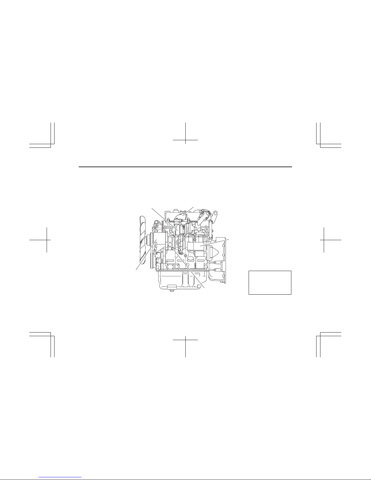
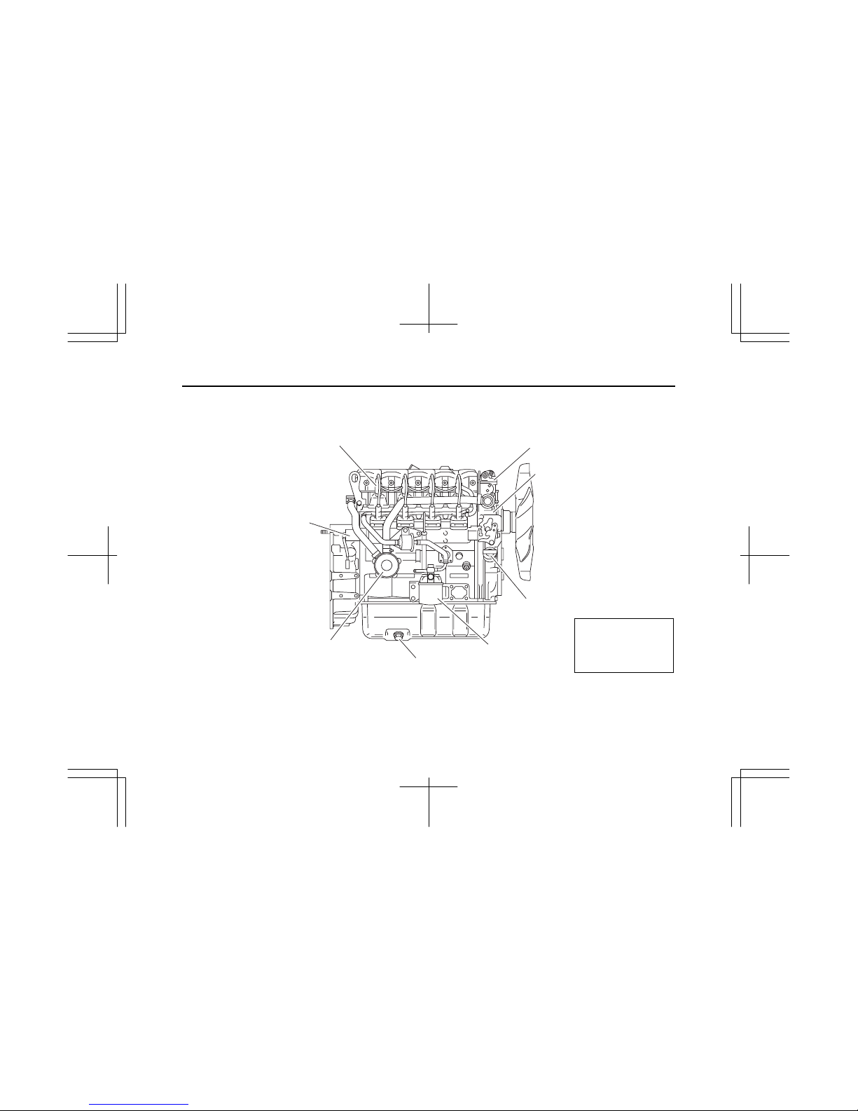
1. MODEL 4LE1T
(1) LH
Air inlet
Generator
Turbocharger
Water drain plug
Starter
IMLE0085
Note:
Engine details may
vary depending on the
specifications.
2
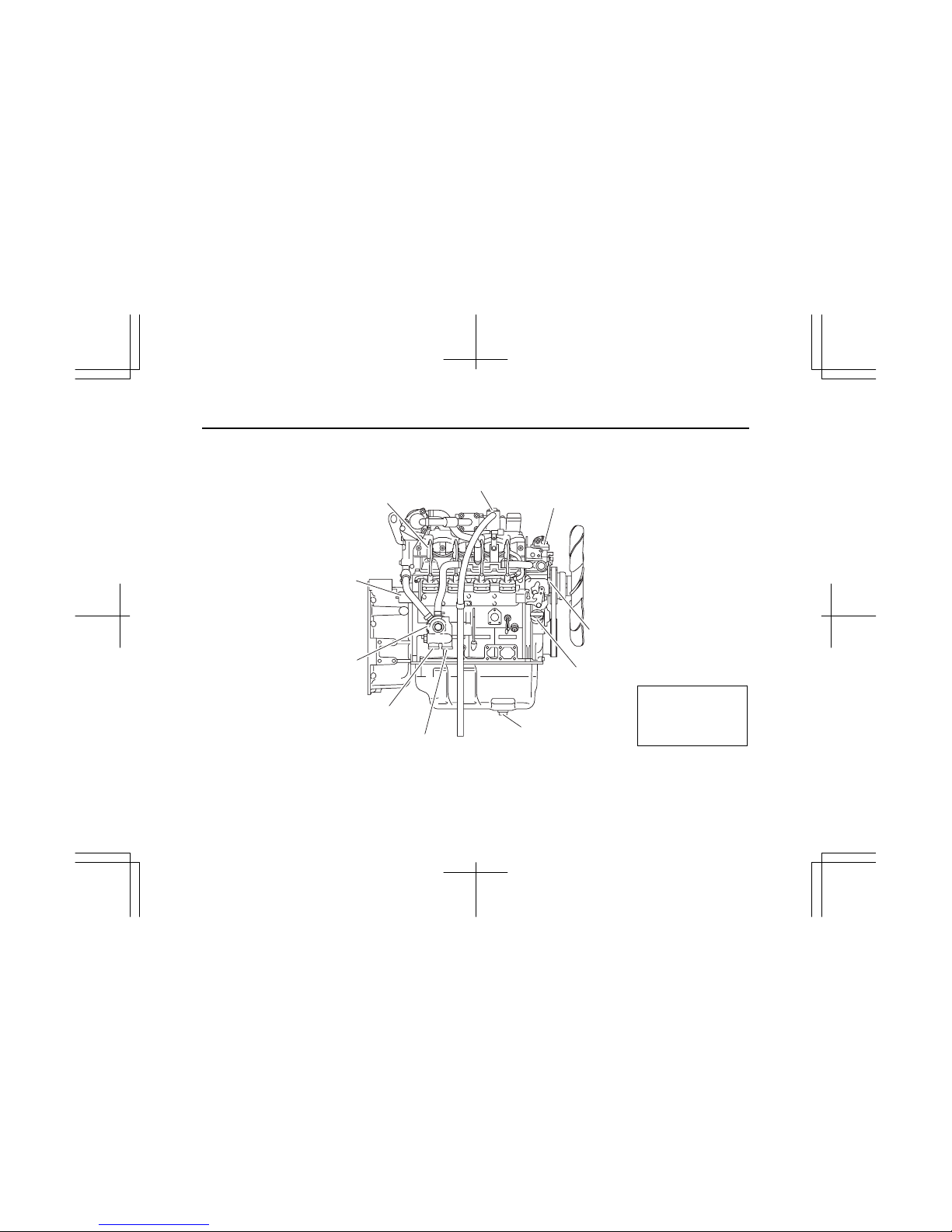
(2) RH
PCV
Nozzle holder
Solenoid stopper
Oil filler cap
Oil drain plug
Oil cooler
From oil filter
To oil filter
Water pump
Thermostat housing
IMLE0086
Note:
Engine details may
vary depending on the
specifications.
3
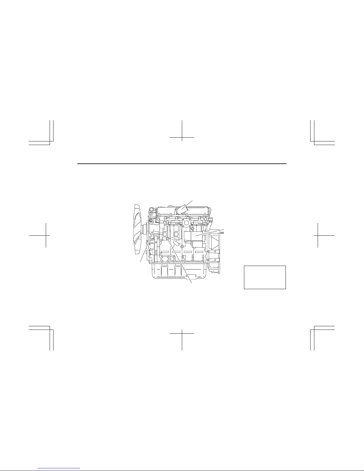
2. MODEL 4LE1NA
(1) LH
Air inlet
Generator
Water drain plug
Starter
IMLE0087
Note:
Engine details may
vary depending on the
specifications.
4
(2) RH
Nozzle holder
Solenoid stopper
Oil filler cap
Oil drain plug
Fuel filter
Oil filter
Thermostat housing
Water pump
IMLE0088
Note:
Engine details may
vary depending on the
specifications.
2. GENERAL INFORMATION
5
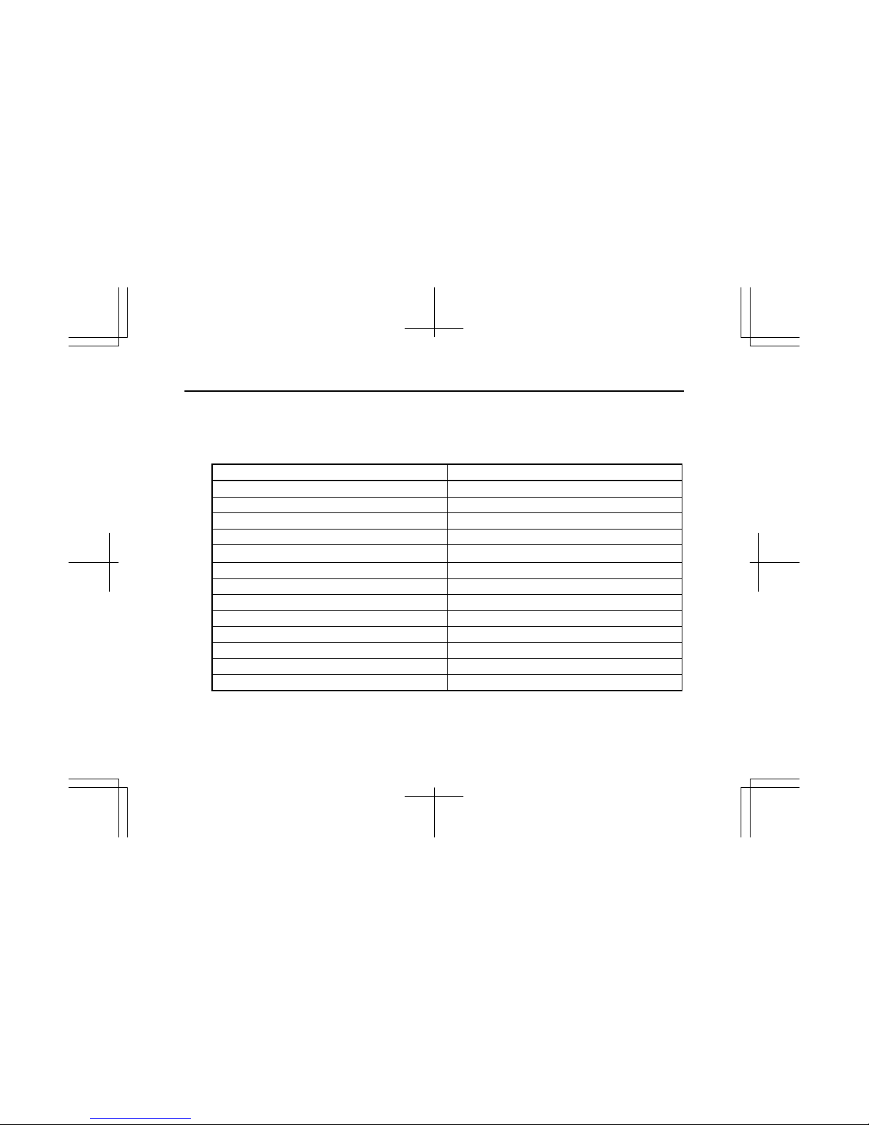
1. EPA AND CARB CERTIFIED ENGINE DATA AND SPECIFICATIONS
Se rapporter à la fin de ce document pour les informations EPA en français.
(1) Model AU-4LE1T
ISUZU engine model name AU-4LE1T
Engine family *SZXL02.2UTA
Engine code 4LE1XXXXX-XX
Engine type Water-Cooled, four cycle, in-line overhead valve type
Combustion type Swirl chamber type
No. of cylinders – bore × stroke mm(in) 4 – 85 × 96 (3.35 × 3.78)
Engine displacement L(cid) 2.179 (133)
Compression ratio 21.5 to 1
Firing order 1 – 3 – 4 – 2
*2 Rated power: SAE NET kW(hp)/min
-1
40 (53.6) / 2200
*2 Fuel flow at max rated power (mm3/stroke) 46.3
Exhaust emission control system EM, IDI, TC, EGR
Injection pump Bosch, PFR type
Governor Variable speed, Mechanical type
* Mark ; Put a letter codes for model year on the top of the letters.
Y : 2000, 1 : 2001, 2 : 2002, 3 : 2003, 4 : 2004, 5 : 2005, 6 : 2006, 7 : 2007, 8 : 2008, 9 : 2009, Model Year
Engine code varies depending on each engine.

6
ISUZU engine model name AU-4LE1T
Injection nozzles Throttle type
Specified fuel Diesel fuel (ASTM D975 No.2-D)
*2 Starter (V-kW) 12 – 2.2
*2 Alternator (V-A) 12 – 50
Specified engine oil (API grade) Refer to 3.LUBRICANT, Engine Oil Selection.
*2 Lub. oil volume L(qts) 7.6 (8.0) – 10.3 (10.9)
Coolant volume (Engine only) L(qts) 2.8 (3.0)
*2 Engine dry weight kg(lb) 190 (419)
Overall length mm(in) 647.5 (25.5)
Overall width mm(in) 523.6 (20.6)
*2 Engine dimensions
Overall height mm(in) 720.8 (28.4)
Valve clearance (cold) mm(in) 0.4 (0.0157)
Nozzle injection pressure MPa(psi) 14.7 (2132)
*2 Injection timing B.T.D.C. 12°
Maker and type of turbocharger IHI, RHF-3
Specification for items marked with an asterisk (*2) will vary according to the type of equipment in which the
engine is installed.

7
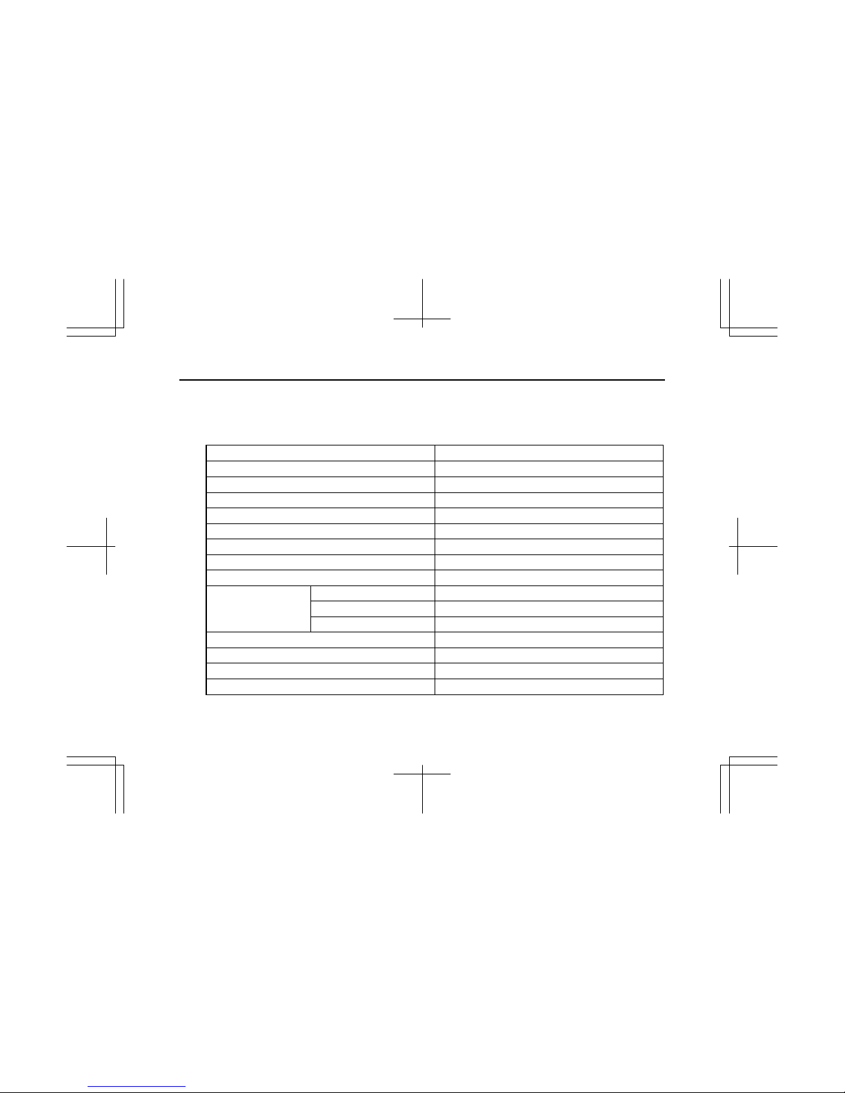
(2) Model BV-4LE1T
ISUZU engine model name BV-4LE1T
Engine family *SZXL02.2VTB
Engine code 4LE1XXXXX-XX
Engine type Water-Cooled, four cycle, in-line overhead valve type
Combustion type Swirl chamber type
No. of cylinders – bore × stroke mm(in) 4 – 85 × 96 (3.35 × 3.78)
Engine displacement L(cid) 2.179 (133)
Compression ratio 21.5 to 1
Firing order 1 – 3 – 4 – 2
*2 Rated power: SAE NET kW(hp)/min
-1
35 (46.9) / 1800
*2 Fuel flow at max rated power (mm3/stroke) 49.7
Exhaust emission control system EM, IDI, TC
Injection pump Bosch, PFR type
Governor Variable speed, Mechanical type
* Mark ; Put a letter codes for model year on the top of the letters.
Y : 2000, 1 : 2001, 2 : 2002, 3 : 2003, 4 : 2004, 5 : 2005, 6 : 2006, 7 : 2007, 8 : 2008, 9 : 2009, Model Year
Engine code varies depending on each engine.
8
ISUZU engine model name BV-4LE1T
Injection nozzles Throttle type
Specified fuel Diesel fuel (ASTM D975 No.2-D)
*2 Starter (V-kW) 12 – 2.0
*2 Alternator (V-A) 12 – 35
Specified engine oil (API grade) Refer to 3.LUBRICANT, Engine Oil Selection.
*2 Lub. oil volume L(qts) 7.6 (8.0) – 10.3 (10.9)
Coolant volume (Engine only) L(qts) 2.8 (3.0)
*2 Engine dry weight kg(lb) 180 (397)
Overall length mm(in) 753.7 (29.7)
Overall width mm(in) 486.2 (19.1)
*2 Engine dimensions
Overall height mm(in) 601.8 (23.7)
Valve clearance (cold) mm(in) 0.4 (0.0157)
Nozzle injection pressure MPa(psi) 14.7 (2132)
*2 Injection timing B.T.D.C. 10°
Maker and type of turbocharger IHI, RHF-3
Specification for items marked with an asterisk (*2) will vary according to the type of equipment in which the
engine is installed.

9
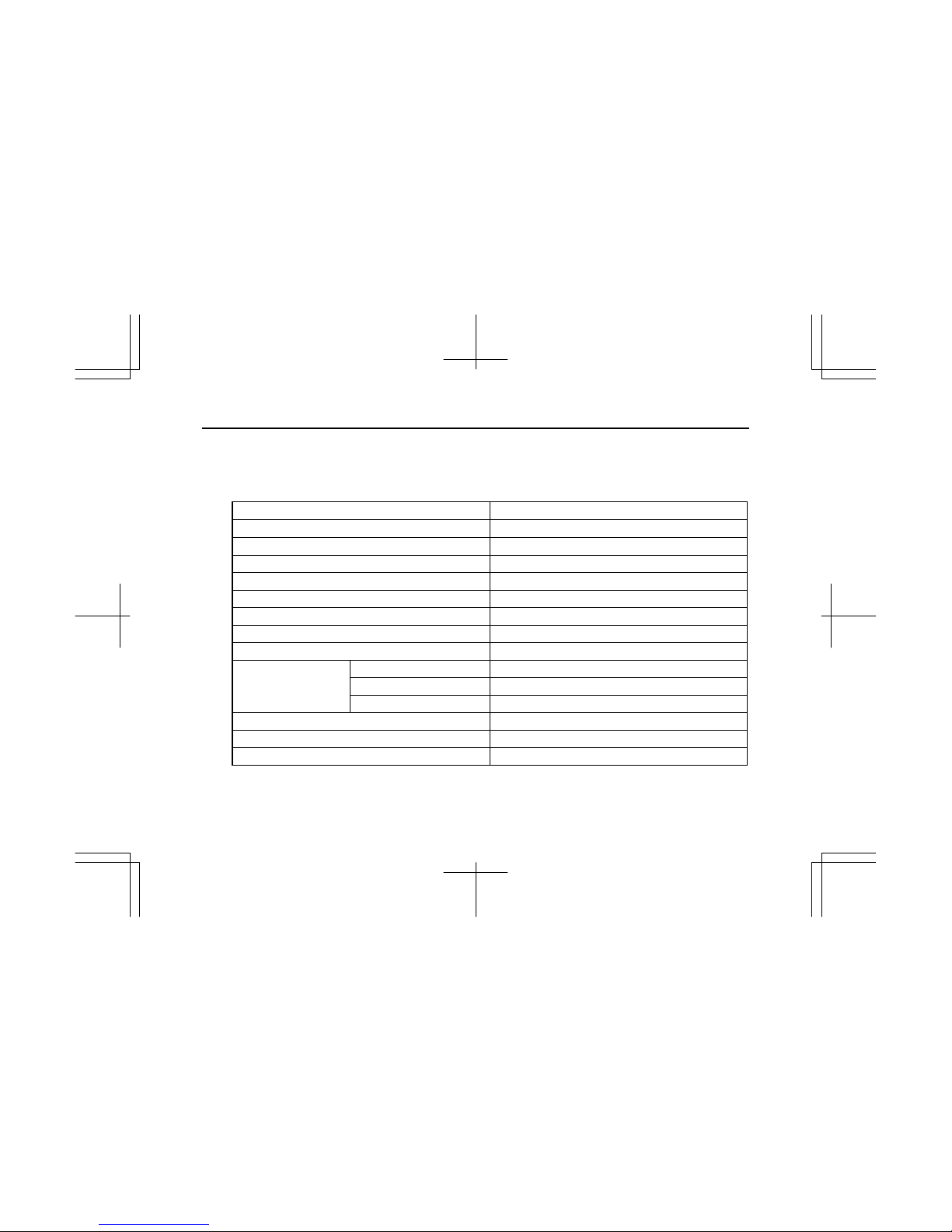
(3) Model AV-4LE1N
ISUZU engine model name AV-4LE1N
Engine family *SZXL02.2VNA
Engine code 4LE1XXXXX-XX
Engine type Water-Cooled, four cycle, in-line overhead valve type
Combustion type Swirl chamber type
No. of cylinders – bore × stroke mm(in) 4 – 85 × 96 (3.35 × 3.78)
Engine displacement L(cid) 2.179 (133)
Compression ratio 21.5 to 1
Firing order 1 – 3 – 4 – 2
*2 Rated power: SAE NET kW(hp)/min
-1
35.9 (48.1) / 2600
*2 Fuel flow at max rated power (mm3/stroke) 35.5
Exhaust emission control system EM, IDI
Injection pump Bosch, PFR type
Governor Variable speed, Mechanical type
* Mark ; Put a letter codes for model year on the top of the letters.
Y : 2000, 1 : 2001, 2 : 2002, 3 : 2003, 4 : 2004, 5 : 2005, 6 : 2006, 7 : 2007, 8 : 2008, 9 : 2009, Model Year
Engine code varies depending on each engine.

10
ISUZU engine model name AV-4LE1N
Injection nozzles Throttle type
Specified fuel Diesel fuel (ASTM D975 No.2-D)
*2 Starter (V-kW) 12 – 2.0
*2 Alternator (V-A) 12 – 35
Specified engine oil (API grade) Refer to 3.LUBRICANT, Engine Oil Selection.
*2 Lub. oil volume L(qts) 5.9 (6.2) – 8.4 (8.8)
Coolant volume (Engine only) L(qts) 2.8 (3.0)
*2 Engine dry weight kg(lb) 170 (375)
Overall length mm(in) 695.7 (27.4)
Overall width mm(in) 486.2 (19.1)
*2 Engine dimensions
Overall height mm(in) 601.8 (23.7)
Valve clearance (cold) mm(in) 0.4 (0.0157)
Nozzle injection pressure MPa(psi) 14.7 (2132)
*2 Injection timing B.T.D.C. 13°
Specification for items marked with an asterisk (*2) will vary according to the type of equipment in which the
engine is installed.

11
(4) Model BV-4LE1N
ISUZU engine model name BV-4LE1N
Engine family *SZXL02.2VNC
Engine code 4LE1XXXXX-XX
Engine type Water-Cooled, four cycle, in-line overhead valve type
Combustion type Swirl chamber type
No. of cylinders – bore × stroke mm(in) 4 – 85 × 96 (3.35 × 3.78)
Engine displacement L(cid) 2.179 (133)
Compression ratio 21.5 to 1
Firing order 1 – 3 – 4 – 2
*2 Rated power: SAE NET kW(hp)/min
-1
26.3 (35.3) / 1800
*2 Fuel flow at max rated power (mm3/stroke) 36.5
Exhaust emission control system EM, IDI
Injection pump Bosch, PFR type
Governor Variable speed, Mechanical type
* Mark ; Put a letter codes for model year on the top of the letters.
Y : 2000, 1 : 2001, 2 : 2002, 3 : 2003, 4 : 2004, 5 : 2005, 6 : 2006, 7 : 2007, 8 : 2008, 9 : 2009, Model Year
Engine code varies depending on each engine.
12
ISUZU engine model name BV-4LE1N
Injection nozzles Throttle type
Specified fuel Diesel fuel (ASTM D975 No.2-D)
*2 Starter (V-kW) 12 – 2.0
*2 Alternator (V-A) 12 – 20
Specified engine oil (API grade) Refer to 3.LUBRICANT, Engine Oil Selection.
*2 Lub. oil volume L(qts) 5.9 (6.2) – 8.4 (8.8)
Coolant volume (Engine only) L(qts) 2.8 (3.0)
*2 Engine dry weight kg(lb) 170 (375)
Overall length mm(in) 671 (26.4)
Overall width mm(in) 496 (19.5)
*2 Engine dimensions
Overall height mm(in) 595 (23.4)
Valve clearance (cold) mm(in) 0.4 (0.0157)
Nozzle injection pressure MPa(psi) 14.7 (2132)
*2 Injection timing B.T.D.C. 10°
Specification for items marked with an asterisk (*2) will vary according to the type of equipment in which the
engine is installed.
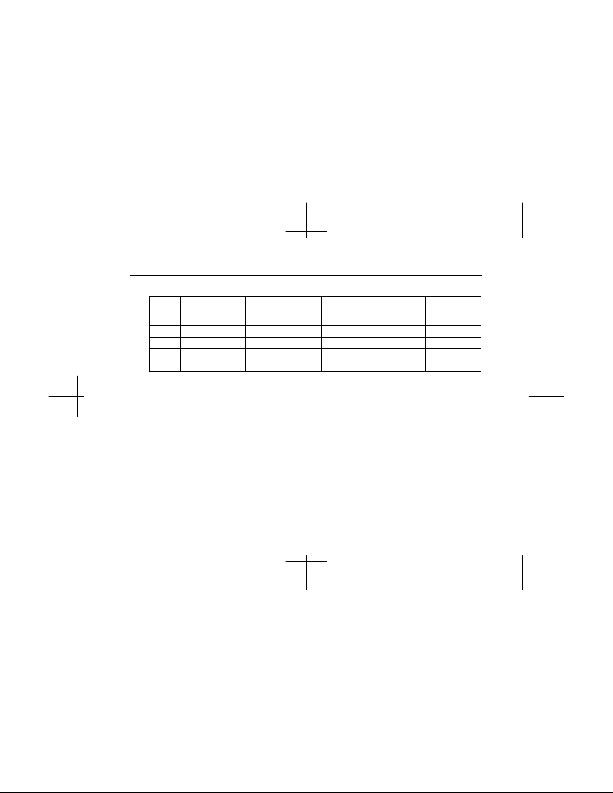
13
(5) Engine family index
Engine Engine family Engine code
Injection nozzle
opening pressure
MPa(psi)
Injection timing
B.T.D.C.
(Static)
4LE1T *SZXL02.2UTA ALL –– ––
4LE1T *SZXL02.2VTB ALL –– ––
4LE1N *SZXL02.2VNA ALL –– ––
4LE1N *SZXL02.2VNC ALL –– ––
* Mark ; Put a letter codes for model year on the top of the letters.
Y : 2000, 1 : 2001, 2 : 2002, 3 : 2003, 4 : 2004, 5 : 2005, 6 : 2006, 7 : 2007, 8 : 2008, 9 : 2009, Model Year
14
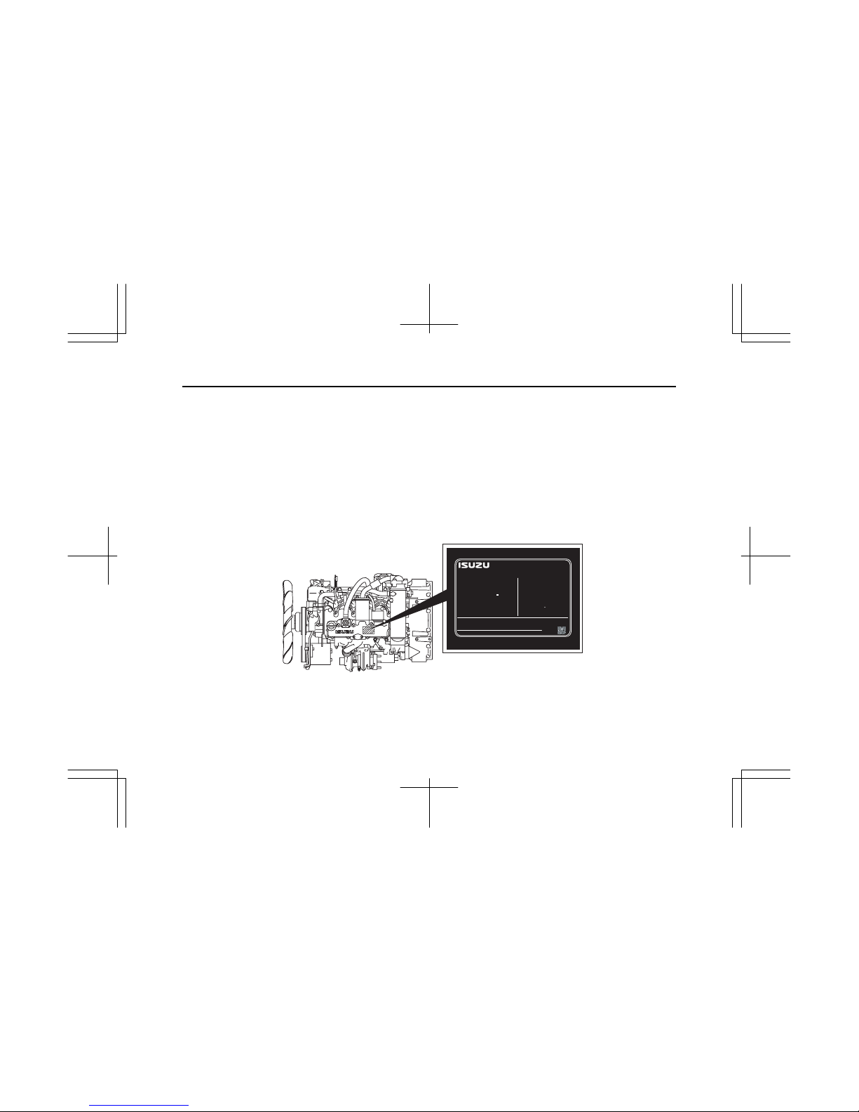
EMISSION CONTROL LABEL: ENGINE LABEL (EPA, EC COMBIND TYPE)
Emission control label is attached at the center of injection pump cover located at the right side of cylinder body, or on the
cylinder head cover.
The location of emission control label attached on the engine may vary depending on the engine specification.
The following is the sample of a label required for engine emission control information, along with location.
4LE1T
ENGINE FAMILY
ENGINE CODE
MODEL
POWER CATEGORY
ADVERTISED POWER (SAE NET)
: XX.X kW / XXXX RPM
FUEL RATE : XX mm
/st.
3
VALVE LASH (COLD)
INL/EXH : XX / XX mm.
INITIAL INJECTION TIMING
CURB IDLE : XXX RPM
EMISSION CONTROL INFORMATION
ISUZU MOTORS LTD. MADE IN JAPAN
THIS ENGINE COMPLIES WITH U.S. EPA REGULATIONS FOR XX MY
NONROAD DIESEL ENGINES AND CALIFORNIA REGULATIONS FOR XX
MY OFF-ROAD DIESEL ENGINES.
EXHAUST EMISSION CONTROL SYSTEM
SEE SERVICE MANUAL FOR
MODEL SPECIFICATIONS.
ENGINE FAMILY : XXXXXXXXXX
ENGINE TYPE : XXXXXXXXXX
THIS ENGINE IS CONFORMED 97/68/EC DIRECTIVE.
ENGINE I.D.NUMBER :
XXXX-XXXX
TYPE APPROVAL NUMBER : XXXXXXXXXXXXXXXXXX
XXXXXX
: XX-XXXXX
: XXXXXXXXX-XX
: XXXXXXX.XXXX
: XX < kW < XX
XXXXXXXXXXXXXXXXXX
: XXXXXXXXXXXXXXXXXX
LOW SULFUR FUEL OR ULTRA LOW
SULFUR FUEL ONLY
XXXXXXXXXX XXXXXXXXXX
: XXX BTDC
IMLE0097
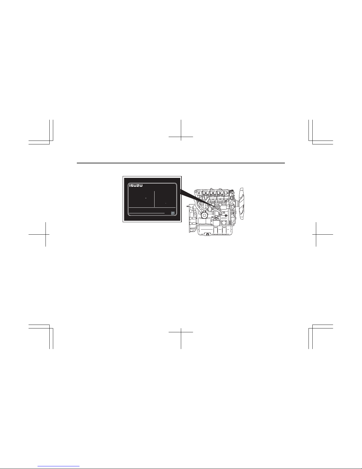
15
4LE1NA
ENGINE FAMILY
ENGINE CODE
MODEL
POWER CATEGORY
ADVERTISED POWER (SAE NET)
: XX.X kW / XXXX RPM
FUEL RATE : XX mm
/st.
3
VALVE LASH (COLD)
INL/EXH : XX / XX mm.
INITIAL INJECTION TIMING
CURB IDLE : XXX RPM
EMISSION CONTROL INFORMATION
ISUZU MOTORS LTD. MADE IN JAPAN
THIS ENGINE COMPLIES WITH U.S. EPA REGULATIONS FOR XX MY
NONROAD DIESEL ENGINES AND CALIFORNIA REGULATIONS FOR XX
MY OFF-ROAD DIESEL ENGINES.
EXHAUST EMISSION CONTROL SYSTEM
SEE SERVICE MANUAL FOR
MODEL SPECIFICATIONS.
ENGINE FAMILY : XXXXXXXXXX
ENGINE TYPE : XXXXXXXXXX
THIS ENGINE IS CONFORMED 97/68/EC DIRECTIVE.
ENGINE I.D.NUMBER :
XXXX-XXXX
TYPE APPROVAL NUMBER : XXXXXXXXXXXXXXXXXX
XXXXXX
: XX-XXXXX
: XXXXXXXXX-XX
: XXXXXXX.XXXX
: XX < kW < XX
XXXXXXXXXXXXXXXXXX
: XXXXXXXXXXXXXXXXXX
LOW SULFUR FUEL OR ULTRA LOW
SULFUR FUEL ONLY
XXXXXXXXXX XXXXXXXXXX
: XXX BTDC
IMLE0110
16
EMISSION CONTROL LABEL: ENGINE LABEL (ONLY EPA TYPE)
Emission control label is attached at a visible point on the equipment.
ENGINE FAMILY
ENGINE CODE
MODEL
POWER CATEGORY
ADVERTISED POWER (SAE NET)
: XX.X kW / XXXX RPM
FUEL RATE : XX mm
/st.
3
VALVE LASH (COLD)
INL/EXH : XX / XX mm.
INITIAL INJECTION TIMING
CURB IDLE : XXX RPM
EMISSION CONTROL INFORMATION
ISUZU MOTORS LTD. MADE IN JAPAN
THIS ENGINE COMPLIES WITH U.S. EPA REGULATIONS FOR XX MY
NONROAD DIESEL ENGINES AND CALIFORNIA REGULATIONS FOR XX
MY OFF-ROAD DIESEL ENGINES.
EXHAUST EMISSION CONTROL SYSTEM
SEE SERVICE MANUAL FOR
MODEL SPECIFICATIONS.
XXXXXX
: XX-XXXXX
: XXXXXXXXX-XX
: XXXXXXX.XXXX
: XX < kW < XX
XXXXXXXXXXXXXXXXXX
: XXXXXXXXXXXXXXXXXX
LOW SULFUR FUEL OR ULTRA LOW
SULFUR FUEL ONLY
XXXXXXXXXX XXXXXXXXXX
: XXX BTDC
ENGINE I.D.NUMBER :
XXXX-XXXX
IMLE0105
17
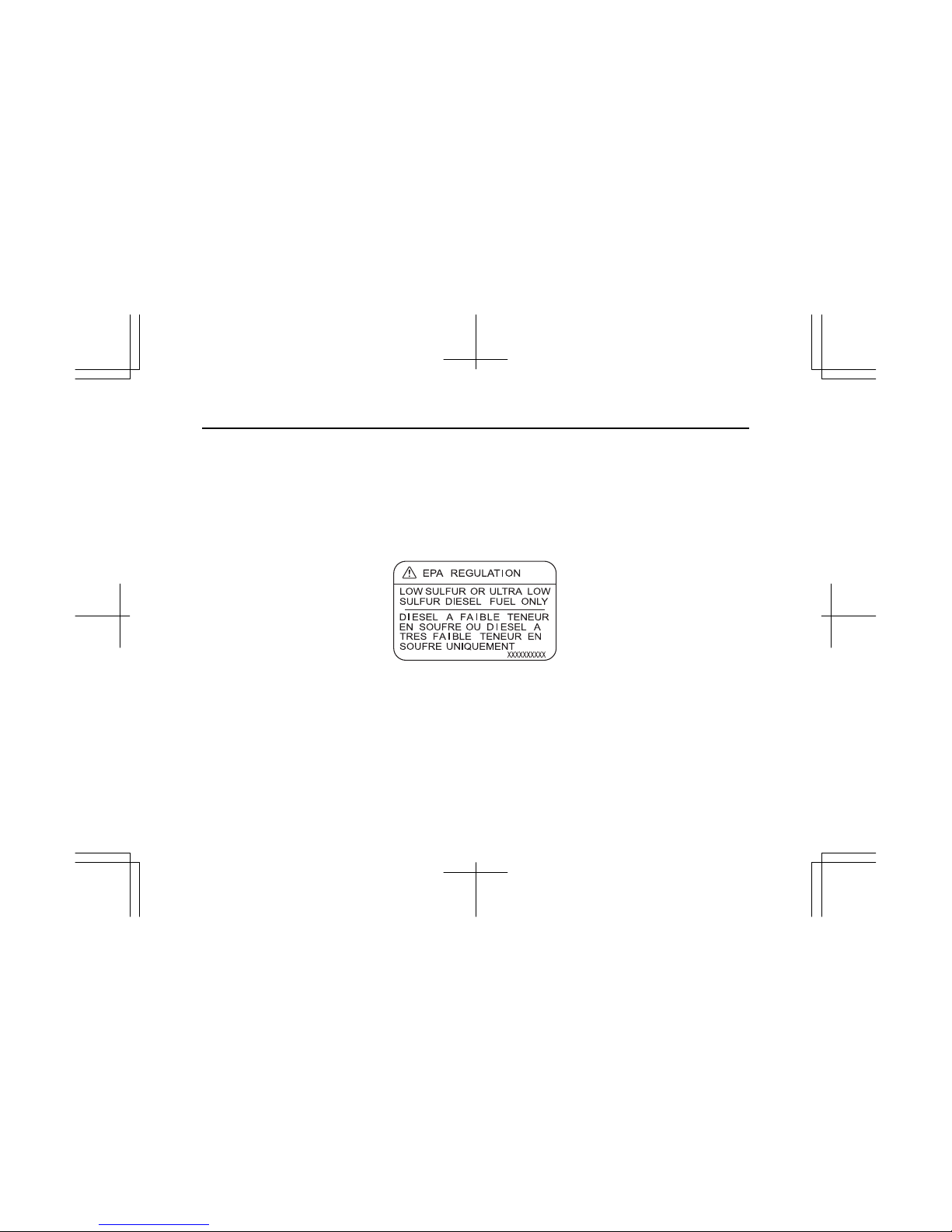
FUEL TYPE IN USE LIMITATION LABEL (FOR EPA)
The fuel type in use limitation label is attached on the filler neck of the fuel tank.
Contents of the label:
LOW SULFUR OR ULTRA LOW SULFUR DIESEL FUEL ONLY
IMLE0066
18
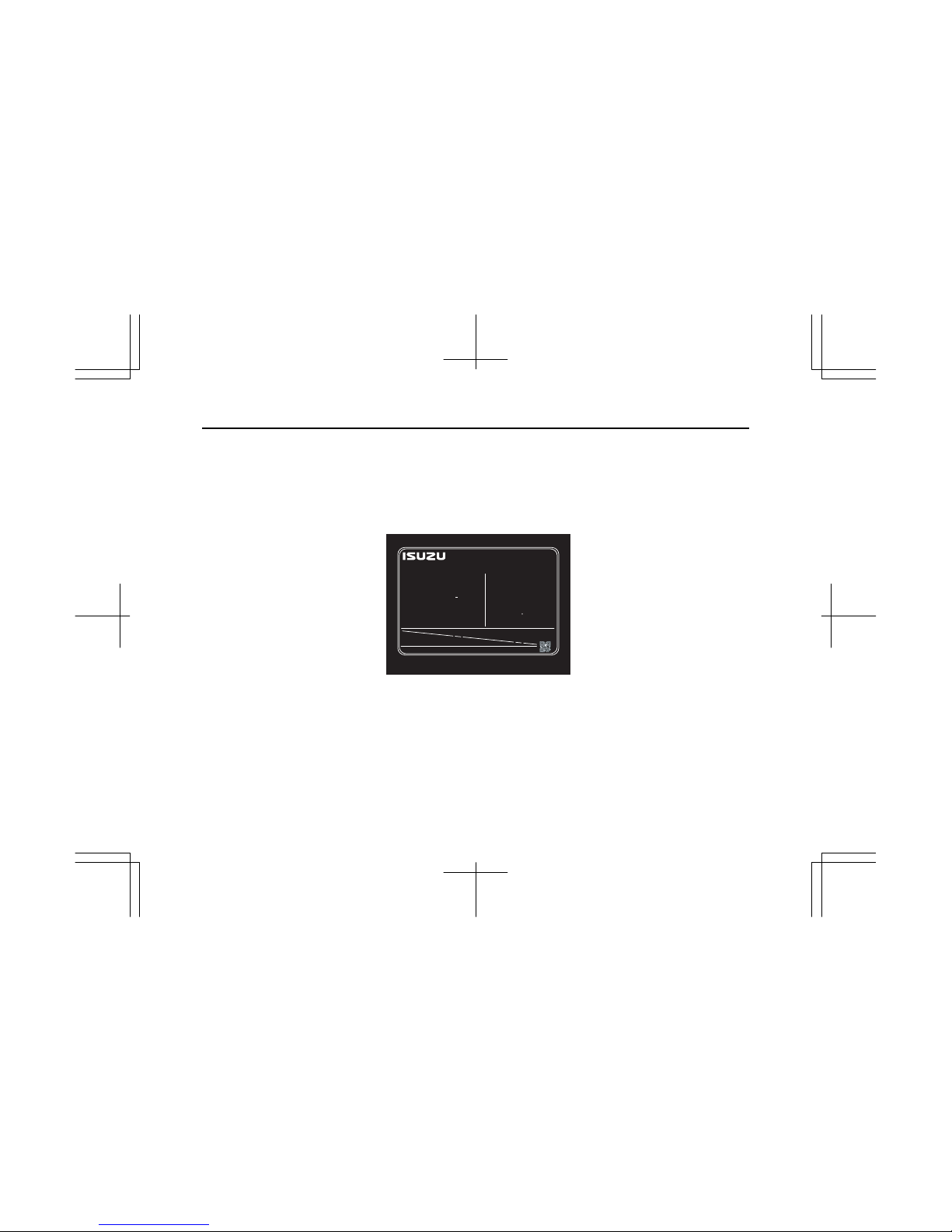
2. EC EMISSION CONTROL LABEL: ENGINE LABEL (ONLY EC TYPE)
Emission control label is attached at the front of injection pump cover located at the right side of cylinder body or the
cylinder head cover.
The following is the detail of a label required for engine emission control information, along with location.
EMISSION CONTROL INFORMATION
ISUZU MOTORS LTD. MADE IN JAPAN
ENGINE FAMILY : XXXXXXXXXX
ENGINE TYPE : XXXXXXXXXX
THIS ENGINE IS CONFORMED 97/68/EC DIRECTIVE.
ENGINE I.D.NUMBER :
XXXX-XXXX
TYPE APPROVAL NUMBER : XXXXXXXXXXXXXXXXXX
XXXXXX
IMLE0106

19
3. ENGINE IDENTIFICATION
(1) Position of Display
The engine serial number is stamped on the front upper right side of
the cylinder body, and the engine model is cast on the rear lower right
side of cylinder body just above the oil cooler.
Further, engine model is described also on an ID label on the top of the
cylinder head cover.

20
Engine model Serial number
4LE1 000000
IMLE0092
21
(2) Confirmation of Engine Serial Number
It is advisable to check the engine serial number, engine model name
and type of machine together with the equipment manufacturer’s name,
as it is required when you contact the distributor for repair service or
parts ordering.
WAR NIN G:
Conduct confirmation of engine serial number with the engine
stopped.
To avoid being injury, don’t check it, while the engine is still
hot.
4. ISUZU ENGINE AFTER SERVICE
(1) Isuzu Engine After Service
Please feel free to contact your ISUZU dealer for periodical inspection
and maintenance.
(2) Isuzu Genuine Parts
The ISUZU genuine parts are identical with those of used in the engine
production, and accordingly, they are warranted by ISUZU MOTORS
LIMITED.
The ISUZU genuine parts are supplied by the ISUZU distributors or the
authorized parts suppliers. Please designate "ISUZU Genuine Parts"
when you need engine parts.
IMLE0073
IMWG0005
3. FUEL, LUBRICANT, AND COOLANT
22
1. FUEL
(1) Fuel Selection
The following specific advantages are required for the diesel fuel.
1) Must be free from minute dust particles.
2) Must have adequate viscosity.
3) Must have high cetane value.
4) Must have high fluidity at low temperature.
5) *Low sulfur or ultra low sulfur diesel fuel only.
6) Must have little residual carbon.
* EPA regulations
Diesel fuels
Applicable Standard Recommendation
JIS (JAPANESE INDUSTRIAL STANDARD) NO. 2
DIN (DEUTSCHE INDUSTRIE NORMEN) DIN 51601
SAE (SOCIETY OF AUTOMOTIVE ENGINEERS)
Based on SAE-J-313C
NO. 2-D
BS (BRITISH STANDARD)
Based on BS/2869-1970
Class A-1
If fuel other than the specified one is used, engine function will be lowered.
23
(2) Fuel Requirements
CAUTION:
Use of other types of fuel than ultra low-sulfur fuel may not
conform to emission regulations.
CAUTION:
The fuel injection pump, injection nozzle or other parts of the
fuel system and engine can be damaged if you use any fuel or
fuel additive other than those specifically recommended by
Isuzu.
Such damage is not Isuzu’s responsibility, and is not covered
by the Warranty. To help avoid fuel system or engine damage,
please heed the following:
•
Some service stations mix used engine oil with diesel fuel.
Some manufacturers of large diesel engines allow this;
however, for your diesel engine, do not use diesel fuel
which has been contaminated with engine oil. Besides
causing engine damage, such fuel can also affect emission
control. Before using any diesel fuel, check with the
service station operator to see if the fuel has been mixed
with engine oil.
•
Do not use any fuel additive (other than as recommended
under "Biocide" in this section). At the time this manual
was printed, no other fuel additive was recommended.
(See your authorized dealer to find out if this has changed.)
•
Take care not to run out of diesel fuel. If you do run out of
fuel, you may need to bleed air out of the fuel injection
pump to re-start the engine after fuel has been added.
24
Your engine is designed to use either Number 1-D or Number 2-D diesel fuel.
However, for better fuel economy, use Number 2-D diesel fuel whenever
possible. At temperatures less than -7°C, (20°F), Number 2-D fuel may
pose operating problems (see "Cold Weather Operation" which follows). At
colder temperatures, use Number 1-D fuel (if available) or use a "winterized"
Number 2-D (a blend of Number 1-D and Number 2-D). This blended fuel is
usually called Number 2-D also, but can be used in colder temperatures than
Number 2-D fuel which has not been "winterized. " Check with the service
station operator to be sure you get the properly blended fuel. Note that
diesel fuel may foam during a fill-up. This can cause the automatic pump
nozzle to shut off even though your tank is not full.
CAUTION:
Do not use home heating oil or gasoline in your diesel engine;
either may cause engine damage.
(3) Replacement Fasteners
CAUTION:
Fuel may be under pressure. Remove the fuel cap slowly to
prevent fuel from spraying out and causing injury.
NOTICE:
Always use diesel fuel.
Use of low quality fuel may adversely affect the engine parts,
and cause failure.
Use of other than specified fuel may adversely affect the
engine or emission control system and cause failure.
If other than specified diesel fuel is used, the machine may not
conform to specifications.

25
(4) Handling of the Fuel
The fuel containing dust particles or water will cause engine failure.
Therefore, the following notice must be observed.
1) Take care to prevent the fuel from entry of dust particles or water when
filling the fuel tank.
When fueling is done from an oil drum directly, keep the drum
stationary over a long time so that clean fuel can be used after the dust
particles or water is completely sedimented.
2) Always fully fill the fuel tank. Drain the sedimented particles in the fuel
tank frequently by opening the tank draining hole.
(5) Water in Fuel
During refueling, it is possible for water (and other contaminants) to be
pumped into your fuel tank along with the diesel fuel. This can
happen if a service station does not regularly inspect and clean its fuel
tanks, or if a service station receives contaminated fuel from its
supplier(s).
To protect your engine from contaminated fuel, there is a fuel filter
system on the engine which allows you to drain excess water.

26
WAR NIN G:
The water/diesel fuel mixture is flammable, and could be hot.
To help avoid personal injury and/or property damage, do not
touch the fuel coming from the drain valve, and do not expose
the fuel to open flames or sparks. Be sure you do not overfill
the container. Heat (such as from the engine) can cause the
fuel to expand. If the container is too full, fuel could be forced
out of the container. This could lead to a fire and the risk of
personal injury and/or machine or equipment damage.
(6) Fuel Filter
1) Be sure to use the genuine fuel filter. The fuel injection system is
precision structure so that its filter has a finer mesh than conventional
one to extend life of the system. Be sure to use "Genuine fuel filter".
2) Replacement interval may be shortened depending on the
characteristic of fuel. Clogged fuel filter may cause to result in stopping
the engine. In a place where fuel gets mixed with foreign matter,
perform early inspection and periodic replacement.
Depending on the machine, the electromagnetic type fuel pump is
equipped in this engine. Periodical replacement or cleaning is required
for this pump filter. (Refer to Filter Replacement or Cleaning)
When the filter exchange of this pump is necessary, please inquire at
your machine supply source or contact ISUZU dealer.
(7) Biocides
In warm or humid weather, fungus and/or bacteria may form in diesel
fuel if there is water in the fuel.

27
CAUTION:
Fungus or bacteria can cause fuel system damage by
plugging the fuel lines, fuel filters or injector. They can also
cause fuel system corrosion.
If fungus or bacteria has caused fuel system problems, you should
have your authorized dealer correct these problems. Then, use a
diesel fuel biocide to sterilize the fuel system (follow the biocide
manufacturer’s instructions). Biocides are available from your dealer,
service stations, parts stores and other automotive places. See your
authorized dealer for advice on using biocides in your area and for
recommendations on which biocides you should use.
(8) Smoke Suppressants
Because of extensive testing of treated fuel versus untreated fuel, the
use of a smoke suppressant additive is not recommended because of
the greater possibility of stuck rings and valve failure, resulting from
excessive ash deposits.
2. LUBRICANT
The quality of engine oil may largely affect engine performance, startability
and engine life.
CAUTION:
Use of unsuitable engine oil will result in piston ring, piston and
cylinder seizure and accelerate the sliding surface wear
causing increased oil consumption, lowered output and, finally
engine failure. To avoid this, use the specified engine oil.

28
(1) Engine Oil Selection
For engine oil, use API grade: CD,CE,CF,CF-4,CH-4,CI-4,CI-4 plus or
ACEA grade: A3/B3,A3/B4,A5/B5,E2,E3,E4,E5,E7 or JASO grade:
DH-1.
The brands/types of oil described below can be used regardless of
specified API or ACEA grade above. Their qualities are guaranteed by
ISUZU.
GRADE
LUBRICATION MAKER BRAND/TYPE
API ACEA JASO
Diesel engine
crankcase
ISUZU GENUINE
ISUZU GENUINE
ISUZU GENUINE
Caltex/Chevron
Shell
Elf
Tot a l
Castrol
BP
IDEMITSU
ExxonMobil
BESCO MULTI-Z TYPE CE (10W-30)
*BESCO MULTI-Z (10W-30)
BESCO S-3 (10W, 20W, 30, 40)
Delo CXJ (15W-40/20W-50/40)
Delo 400 Multigrade (15W-40)
Rimula X (15W-40)
Rimula D (15W-40/30/40)
Perfo 3F (15W-40)
Rubia XT (15W-40)
RX Super Plus (15W-40)
Tection J Plus (15W-40)
BP Vanellus C6 (15W-40)
APOLLOIL EX (10W-40)
APOLLOIL TOUGH RUNNER (10W-30,15W-40)
APOLLOIL MULTI RUNNER (10W-30, 15W-40)
*2 APOLLOIL SUPER WIDE DH-1(10W-30, 15W-40)
Essolube XTJ (15W-40)
Exxon/Essolube XD-3 (15W-40)
Mobil Delvac 1300 Super (15W-40)
Mobil Delvac 1 (5W-40)
CE
CD/CF/CF-4
CD
CF
CE/CF/CI-4
CH-4
CF
CF-4/CE
CF-4
CH-4
CH-4
CH-4
CF
CF
CF-4/CE
CF-4
CF-4
CI-4
CI-4 Plus
CI-4 Plus
E3/E5
E3
B2/E2
E2
E3
E3/B3
E3
E7/E5
E7/E5/E4/E3
DH-1
DH-1
DH-1
DH-1
DH-1
DH-1
DH-1
DH-1
DH-1
DH-1
DH-1
* Initial Engine Oil from Engine plant
*2 Initial Engine Oil from Engine plant (Only a Part of Models)

29
(2) Oil Viscosity
Engine oil viscosity largely affect engine startability, performance, oil
consumption, speed of wearing and occurrence of seizure, etc. Using
lubricants whose viscosity selected according to the atmospheric
temperature is important.
CAUTION:
1. Using a mixture of different brand or quality oils will
adversely affect the original oil quality; therefore, never mix
up different brand or different type oils.
2. Don’t use API, CA, CB grade and reconstituted engine oil.
3. Engine damage due to improper maintenance, or using oil
of the improper quality and/or viscosity, is not covered by
the warranty.
SAE 20, 20W
SAE 20, 20W
SAE 30
SAE 30
SAE 10W
SAE 10W
SAE 40
SAE 40
30 C
(86 F)
-25 C
(-13 F)
25 C
(77 F)
15 C
(59 F)
-0 C
(32 F)
-15 C
(5 F)
SAE 10W-30
SAE 10W-30
SAE 15W-40, 20W-40
SAE 15W-40, 20W-40
[Single-grade]
[Multi-grade]
Ambient
Temperature
SAE 20, 20W
SAE 30
SAE 10W
SAE 40
SAE 10W-30
SAE 15W-40, 20W-40
-20 C
(-4 F)
SAE 5W-20
SAE 5W-20
SAE 5W-20
ENGINE OIL VISCOSITY GRADE - AMBIENT TEMPERATURE
IMLE0040

30
3. COOLANT
Always refer to the chart to determine the correct cooling water to
antifreeze solution mixing ratio.
CAUTION:
1. Supplement inhibitors or additives claiming to provide
increases cooling capability that have not been specifically
approved by Isuzu are not recommended for addition to the
cooling system.
2. When supplying or replacing coolant, do not use water of
well or river, but be sure to use tap water (soft water),
distilled water or demineralized water.
3. It is strongly recommended to use Isuzu genuine engine
coolant or equivalent for addition or replacement.
4. Coolants from other brands often do not contain
anti-corrosive, and use of such products could result in
corrosion of the engine and radiator.
5. If the density of Isuzu genuine engine coolant exceeds
60%, the reduced specific heat characteristic of the coolant
could result in overheating. If the densit
y
is below 20%, the
anticorrosion characteristic may degrade. Adjust the
coolant density in the range from 20% to 60% according to
the situation.
10 20 30 40 50
0
-20
-40
-50
-10
-30
0
Mixing ratio (%)
Freezing point (℃)
IMJJ0025

4. ENGINE OPERATION
31
Engine Exhaust Gas Caution
(Carbon Monoxide)
WAR NIN G:
Do not breathe exhaust gas because it contains carbon
monoxide, which by itself has no color or odor. Carbon
monoxide is a dangerous gas. It can cause unconsciousness
and can be lethal.
We recommend that the exhaust system be inspected by
competent technician:
•
Each time the machine has an oil change.
•
Whenever a change is noticed in the sound of the exhaust
system.
•
Whenever the exhaust system is damaged or becomes
corroded.
See "Maintenance Schedule" in Section 8 of this manual for
parts requiring inspection.
Do not run the engine in confined areas (such as garages or
next to a building) any more than needed to move the machine
or the equipment.
Keep the exhaust tailpipe area clear of snow and other
material to help reduce the buildup of exhaust gases or the
equipment. This is particularly important when parked in
blizzard conditions.

32
1. CHECK BEFORE OPERATION
WAR NIN G:
For Safety’s sake, conduct the inspection before start-up with
the engine stopped.
CAUTION:
As the remote filter is used, the engine oil is filled above the
specified level. (Turbocharged engine only)
Adjust the engine oil level as required.
(1) Engine Oil Level
1) Place the engine on a level surface.
2) Remove the dipstick from the crankcase, wipe it with clothing.
Insert it fully and take out it gently again.
Without turbocharger
With turbocharger
Dipstick
Dipstick
IMLE0067

33
Check the oil level by the level marks on the dipstick. The oil level
must be between the "Max" level mark and the "Min" level mark as
illustrated.
Take care not to add too much engine oil.
• Drain oil to the max. oil level if oil level is above the max. level
mark.
• Add oil to the max. oil level if oil level is below the min. level mark.
3) Also check the sample oil on the dipstick for fouling and degrees of
viscosity.
CAUTION:
Oil level check must be made ten or twenty minutes later after
the engine has been stopped. When the oil level check is
necessary while the engine is running, stop the engine and
keep it stationary ten or twenty minutes until the oil thoroughly
flows down to the crankcase.
4) Oil is poured either through the oil filler at the front of the cylinder head
cover or through the oil filler on the right side of the timing gear case.
A certain period of time is required before the engine oil completely
flows down from the oil filler to the crankcase.
Check the oil level ten or twenty minutes after oil replenishment.
CAUTION:
If the engine oil is splashed on the fan belt, it causes belt
slippage or slackness; therefore, take care to avoid it.
Max. level
Min. level
Dipstick
IMLE0068
Oil filler cap
IMLE0093

34
WAR NIN G:
1. In adding oil, take care not to spill it. If you spill oil on
engine or equipment, wipe it properly, or this could lead to a
fire and the risk of personal injury and/or equipment
damage.
2. For model that employs the closed PCV, excessive oil may
cause hunting in oil pressure, increase in the oil
temperature, oil seepage from the intake system and
engine oil intrusion into the combustion chamber, resulting
in engine damage.
(2) Fan Belt Check
Check the fan belt for tension and abnormalities.
WAR NIN G:
For the sake of safety, before conducting fan belt check, make
sure that the engine is stopped and is not be operated during
check.
1) When the belt is depressed with the thumb (about 100 N (22 lb)
pressure) at the midway between the alternator pulley and fan pulley,
the belt tension is correct as the following:
Fan belt slackness : 8 – 10 mm (0.31 – 0.39 in)
When the belt tension is too high, it will result in alternator failure.
Contrarily, loose belt will cause belt slippage which may result in
damaged belt and abnormal noise.
IMLE0012

35
2) Check the belts. Replace them if any damage is found.
CAUTION:
Replace all belts as a set even when one is not usable.
Single belt of similar size must not be used as a substitute for
a matched belt set. Otherwise, premature belt wear would
result because of uneven belt length.
(3) Coolant Level Check
1) Without the reserve tank
Remove the radiator filler cap, and check the coolant level as well as
the degrees of fouling.
Proper coolant level is about 10 mm higher from the radiator core top.
2) With the reserve tank
The coolant level must be between "FULL" and "LOW" marks on the
reserve tank.
Check and see that the level is correct.
When the coolant level is lower than the "LOW" mark, replenish the
reserve tank by the filler port, but when the reserve tank is empty,
replenish by the radiator filler port.
WAR NIN G:
When removing the radiator filler cap while the engine is still
hot, cover the cap with clothing, then turn it slowly to
g
radually
release the internal steam pressure. This will prevent you
from getting burnt with hot steam spouted out from the filler
port.
CAUTION:
Use Isuzu genuine anti-freeze (ethylene-glycol based) or
equivalent with the specified mixing ratio.

36
(4) Radiator Cap Condition
After the replenishment of the coolant, install the radiator cap.
Make sure the cap is securely installed.
(5) Battery Cable Connection
Check the battery cable connections for looseness or corrosion.
The loosened cable connection will result in hard engine starting or
insufficient battery charge.
The battery cables must be tightened securely.
CAUTION:
Never reverse "+" and "–" terminals when reconnecting cables
after disconnection.
Even a short period of reverse connection will damage the
electrical parts.
Terminal
Battery cable
Battery cable
24V
Terminal
12V
Battery cable
IMLE0069

37
(6) Battery Electrolyte Level
The amount of electrolyte in the batteries will be reduced after
repeated discharge and recharge.
Check the electrolyte for the level in the batteries, replenish with a
commercially available electrolyte such as distilled water, if necessary.
The battery electrolyte level checking procedure will vary with battery
type. Follow the equipment manufacturer’s instructions.
CAUTION:
Do not replenish with dilute sulfuric acid in the daily service.
WAR NIN G:
1. When inspecting the batteries, be sure to stop the engine.
2. As diluted sulfuric acid is used as electrolyte, be careful not
to stain your eyes, hands, clothes, and metals with the
electrolyte. If it gets in your eye, wash with a large amount
of water at once. Then go and see a doctor.
3. As highly flammable hydrogen gas is rising from the
batteries, do not make a spark or use fire in any other way
near the batteries.
4. When handling such metallic articles as a tool near the
batteries, be sure not to contact
○
+
terminal. As the
machine body is
○
−
, it may cause a big danger.
5. When disconnecting the terminals, start with
○
−
terminal.
When connecting them, connect the
○
−
terminal last.
Regular position
Shortage
Proper
Excess
IMWG0013

38
2. ENGINE STARTING
(1) Pre-starting Preparation
1) Make sure that all hydraulic control levers etc. on the equipment are in
the NEUTRAL position.
2) Set the engine stop knob in the START position. (It is unnecessary for
the engine equipped with the engine shutdown switch.)
3) Switch ON the battery switch (if so equipped).
4) Insert the starter switch key into the switch key hole.
Turn the key clockwise to DRIVE position and, make sure that the
meters and warning lamps are actuated.
OFF
DRIVE
START
AUTO RETURN
IMWG0014
In case of the type with QOS system
IMLE0041
In case of the type with control resistance

39
(2) Pre-heating Procedures
As an engine starting aid, pre-heating is required in a cold engine
starting.
The type with QOS system:
This pre-heating uses "QOS," a quick pre-heating system which
automatically controls pre-heating time utilizing coolant temperature to
conduct the irreducible minimum of pre-heating.
1) Turn the key to the DRIVE position, and the glow plugs built in the
engine will grow red-hot to pre-heat the engine. At this time the
pre-heating indicator lamp on the meterboard is actuated.
2) When the pre-heating indicator lamp goes out, try starting the engine at
once.
Relationship between water temperature and pre-heating time (For
ref.)
20°C (68°F) ········· About 0.5 sec.
5°C (35°F) ··········· About 1.5 sec.
0°C (32°F) ··········· About 2 sec.
-15°C (5°F) ·········· About 6.3 sec.
The type with a control resistance
1) Turn the starter switch key counter-clockwise to PRE-HEAT position in
order to heat the glow plugs on the engine.
The Pre-heating time of 5 seconds is required until the control
resistance coil becomes red.
2) Turn the starter switch key clockwise to START position as soon as the
control resistance coil red heat.

40
WAR NIN G:
Make sure that there is no flammable near outlet port of
exhaust gas at engine starting. It is very dangerous due to
deformation, discoloration or a fire.
(3) Engine Starting
1) Depress the engine throttle lever or throttle pedal and turn the starter
switch key clockwise to START position.
The cranking period must not exceed ten seconds.
Continuous starter operation of more than ten seconds will lead to
overdischarge of the batteries as well as starter seizure.
Release the starter switch after the engine starts.
The switch will return to the "DRIVE" position automatically.
For the engine equipped with a safety unit, the starter circuit is
automatically turned off when the engine starts. This prevents the
starter from overrunning.
If the engine cannot be started in one time attempt, keep the batteries
and the starter stationary at least 30 seconds for their functional
recovery, then repeat the pre-heating and the starting operations.
CAUTION:
Continuous re-engagement of the starter to the flywheel ring
g
ear without giving them a break will result in the damaged
starter pinion gear and flywheel ring gear.
2) If, despite repeated operations, the engine does not start, wait for a
minute or more until the functions of the batteries and starter are
recovered and then repeat pre-heating and starting operations.

41
3) When repeating starting operation, return the key to the OFF position
and then pre-heat and start the engine once again.
If the engine still remains unstarted, something may be wrong with the
engine. Check the repeated parts to locate the cause.
CAUTION:
Do not use starting "aids" in the air intake system. Such aids
can cause immediate engine damage.

42
3. CHECK AND OPERATION AFTER THE
ENGINE START-UP
(1) Warming-up Operation
Do the warming-up operation at 1000 min-1 about ten minutes after the
engine has started.
As the lubrication for the entire engine systems will be done in this
warming-up, do not speed up and load it abruptly.
Particularly, observe this in cold season operation.
(2) Check after the Engine Start-up
Check the following items in the engine warming-up operation.
Engine oil pressure
Although the engine oil pressure gauge readings vary depending on
ambient temperature, a type of oil or engine specification, the gauge
registers the values of the following in the warming-up.
Oil pressure : 147 kPa (21 psi) /1000min
-1
294 kPa (43 psi) /1800min
-1
343 to 686 kPa (50 to 100 psi) /2200min
-1
In the oil pressure warning lamp type, make sure that the lamp is off.
Charge condition
The charge condition is normal when once the ammeter registers plus
side greatly in the engine starting, then gradually the meter registering
will be minimized.
In the warning lamp type, make sure that the lamp is completely off
during the warming-up.

43
Engine noise and exhaust smoke color
Pay attention to engine noise and, if any abnormal noise is heard,
check the engine to detect the cause.
Check the fuel combustion condition by exhaust smoke color.
The exhaust smoke color after engine warming-up and at no-load
operation.
Colorless or light blue.... Normal (Perfect combustion)
Black color..................... Abnormal (Imperfect combustion)
White color.................... Abnormal (Oil coming up and coming down)
CAUTION:
Engine noise after start-up might be noisy than that of
warmed-up engine and, the exhaust smoke color also being
more whitish than the normal condition.
However, it will be normalized after warming-up engine.
Leakage in the systems
CAUTION:
When checking, leaking liquid from engine may be splattered
during engine operation. It may cause a burn. Approach the
engine gradually from a long distance and then check it.

44
Check the following items:
• Lube oil leakage
Check both sides and bottom of the engine assembly for lube oil
leaks, paying particular attention to the lube oil pressure gauge
pipe joint, lube oil filter and lube oil pipe joints.
• Fuel leakage
Check the fuel injection pump, fuel lines and fuel filter for leakage.
• Coolant leakage
Check the radiator and water pump hose connections also the
water drain cocks on the radiator and cylinder body for leakage.
• Exhaust smoke or gas leakage.
Checking coolant level
The coolant level could drop depending on the equipment because the
mixed air is expelled in about 5 minutes after the engine started.
Stop the engine, remove radiator cap, and add coolant.
WAR NIN G:
Hot steam will rush out and you could get burnt, if the radiator
cap is removed when the engine is hot.
Cover the radiator cap with a thick cloth and loosen the cap
slowly to reduce the pressure, then remove the cap.

45
4. CARE IN THE ENGINE OPERATION
In the engine operation, always pay attention to the following items if the
engine indicates any sign of abnormalities.
(1) Engine Oil Pressure
Engine oil pressure is normal when the oil pressure gauge shows the
values of the following in the engine warmed-up condition.
Oil pressure : 147 kPa (21 psi) /1000min
-1
294 kPa (43 psi) /1800min
-1
343 to 686 kPa (50 to 100 psi) /2200min
-1
In the continuous engine operation, engine oil pressure is slightly lower
than the pressure at start-up time.
Also, make sure that the oil warning lamp is off.
If, in continuous engine operation, the engine oil pressure warning
lamp is off, engine oil pressure is normal.
When the engine oil pressure gauge shows the following abnormal
conditions, stop the engine immediately and check the engine oil
amount in the oil sump and oil leakage:
• The engine oil pressure gauge shows below 200 kPa (28 psi)
though the engine speed is raised.
• The oil pressure gauge indicator oscillates greatly in the engine
low speed range.
• When the engine oil pressure warning lamp goes on and off
repeatedly.
When not lack of engine oil or no oil leakage is found, contact your
equipment supplier to determine the cause of the abnormal reading.

46
(2) Coolant Temperature
The engine performance will be adversely affected if engine coolant
temperature is too hot or too cold.
The normal coolant temperature is 75 to 90°C (167 to 194°F).
Overheating
WAR NIN G:
If the Engine Coolant Temperature Gage shows an overheat
condition or you have other reason to suspect the engine may
be overheating, continued operation of the engine (other than
as spelled out here) even for a short period of time may result
in a fire and the risk of personal injury and severe vehicle or
equipment damage. Take immediate action as outlined
following.
If you see or hear escaping steam or have other reason to suspect
there is a serious overheat condition, stop and park the machine or
equipment as soon as it is safe to do so and then turn off the engine
immediately and get out of the machine or equipment.
The engine cooling system may overheat if the engine coolant level is
too low, if there is a sudden loss of engine coolant (such as hose
splitting) or if other problems occur. It may also temporarily overheat
during severe operating condition such as:
• Climbing a long hill on a hot day.
• Stopping after high rpm.

47
If the Engine Coolant Temperature gage shows an overheat condition,
or you have reason to suspect the engine may be overheating, take the
following step:
• If your air conditioner (if equipped) is on, turn it off. And turn on
the heater.
• Don’t turn off your engine.
• With the transmission in Neutral, increase the engine speed to
about one-half full operating speed or 1200 RPM, maximum.
Bring the idle speed back to normal after two or three minutes.
If the engine coolant temperature does not start to drop within a minute
or two:
• Let the engine run at normal idle speed for two or three minutes.
If the engine coolant temperature does not start to drop, turn off the
engine and get out of the machine or equipment then proceed as
follows:
WAR NIN G:
To help avoid being burned-
•
Do not open the engine access cover if you see or hear
steam or engine coolant escaping from the engine
compartment. Wait until no steam or engine coolant can
be seen or heard before opening the engine cover.
•
Do not remove the radiator cap or engine coolant reserve
tank cap if the engine coolant in the tank is boiling. Also
do not remove the radiator cap while the engine and
radiator are still hot. Scalding fluid and steam can be
blown out under pressure if either cap is taken off too soon.

48
If no steam or engine coolant can be seen or heard, open the engine
access cover. If the engine coolant is boiling, wait until it stops before
proceeding. Look at the see-through reserve tank. The engine
coolant level should be between the "MAX" and "MIN" marks on the
reserve tank. If necessary, pour engine coolant into the reserve tank
only, never directly into the radiator. Also, do not check engine
coolant level at the radiator.
Make sure the fan belts are not broken, or off the pulleys and that the
fan turns when the engine is started.
If the engine coolant level in the reserve tank is low, look for leaks at
the radiator hoses and connections, heater hoses and connections,
radiator, and water pump. If you find major leaks, or spot other
problems that may have caused the engine to overheat, do not run the
engine until these problems have been corrected. If you do not find a
leak or other problem, carefully add engine coolant to the reserve tank.
(Engine coolant is a mixture of ethylene glycol antifreeze and tap water
(soft water), distilled water or demineralized water. See "Engine Care
in cold season" in Section 6 for the proper antifreeze and mixture.)
WAR NIN G:
To help avoid being burned, do not spill antifreeze or engine
coolant on the exhaust system or hot engine parts. Under
some conditions the ethylene glycol in engine coolant is
combustible.

49
If the engine coolant level in the reserve tank is at the correct level but
there is still an indication on the instrument panel of an overheat
condition:
• YOU MUST LET ENGINE COOL FIRST. You may then add
engine coolant directly to the radiator.
Once the Engine Coolant Temperature Gage no longer signals an
overheat condition, you can resume operating at a reduced speed.
Return to normal operating after about ten minutes if the gage pointer
does not again show an overheat condition.
If no cause for the overheat condition was found, see a qualified
service technician.
Overcooling
The engine operation at low coolant temperature will not only increase
the oil and fuel consumption but also will lead to premature parts wear
which may result in engine failure.

50
(3) Engine Hourmeter (Engine Operation Hour Indicating)
(If so equipped)
This meter indicates the engine operation hours. Make sure that the
meter is always working during engine operation.
Periodical engine maintenance is scheduled on the operation hours
indicated on the hourmeter.
(4) Liquid and Exhaust Smoke Leakage
Be careful with lubricant, fuel, coolant and exhaust smoke leakage.
(5) Abnormal Engine Noise
Pay attention to the noise from the engine or other related parts,
checking if the noise is normal.
(6) State of the Exhaust Smoke
Be careful with exhaust smoke color, check if it is whitish or blackish.

51
5. ENGINE STOPPING
1) Make sure that all of the control levers on the equipment are in
NEUTRAL position.
2) Before stopping the engine, cool down the engine by operating it at low
idle speed about three minutes.
In this operation, check the engine noise and the engine oil pressure
for abnormalities.
CAUTION:
In the turbocharged engine, if the engine is stopped
instantaneously, a dry condition produced by high temperature
will take place in the turbocharger rotating parts which may
cause lack of lubrication. This will result in turbocharger
failure.
3) To stop the engine, turn the starter switch key to OFF position. The
engine stop solenoid automatically shut off the fuel to stop the engine.
Switch off the battery (if so equipped).
CAUTION:
Leaving the starter switch key in the DRIVE position for a long
while after the engine has been stopped, will discharge the
batteries wastefully.

52
6. OPERATION AND CARE FOR NEW
ENGINE
Your ISUZU engine is carefully tested and adjusted in the factory, however,
further, thorough run-in (i.e. break-in) operation is necessary.
If the new engine is harshly operated, lubricating oil film will be reduced
leading to abnormal wear or seizure. Particularly, avoid a harsh engine
operation within the initial 100 operation hours observing the following
notice.
1) Do the warming-up operation continuously until the engine is
warmed-up. In this operation, do not race the engine.
2) Also do not operate the engine with rapid acceleration, rapid machine
starting and continuous high speed operation.
7. ENGINE CARE FOR OVER-COOLING
Engine over-cooling cause premature wear and increased fuel consumption.
When the coolant temperature is not raised to 75 to 90°C (167 to 194°F)
indefinitely, take an action to recover this with means of radiator curtain or
such like.

53
8. OPERATION AND CARE FOR
TURBOCHARGED ENGINE
(1) Engine Starting
The warming-up operation of the engine should be done in the way
separately described. In addition, ensure the bearings supporting the
rotating parts of the turbocharger are sufficiently lubricated.
1) Do not race cold engine.
2) When starting the engine after a long period (more than one month) of
standing, proceed as follows:
Pour engine oil into the turbocharger through the oil inlet port with the
air intake duct and oil inlet side pipe removed. Then turn the impeller
by hand to thoroughly lubricate the bearings.
3) When pouring oil in, do not allow dust particles and other foreign
materials to enter through the opening.
On completion of this operation, securely install the oil pipe and air
intake duct.
(2) Engine Stopping
Whenever stopping the engine, the last about 3 minutes of operation
should be at idle. After hard operation, at least 5 minutes of operation
should be at idle until the turbocharger cools down. This allows the
turbocharger to return to idle speed while engine oil pressure is
available for lubrication.
CAUTION:
Failure to cool down turbocharger at idle could result in
insufficient lubrication of its bearings and their shortened life.

54
9. STARTING THE ENGINE AFTER BEING
LEFT UNUSED FOR A LONG PERIOD OF
TIME
When the machine or equipment is left unused for "more than three
months" without running the engine (warming up), conduct a thorough
inspection of the machine before starting the engine.
Crank the engine for 10 seconds and then stop it for 30 seconds with the
fuel cut. Repeat this procedure for three times. This sends the oil to each
part.
After starting the engine, be sure to warm it up for more than ten minutes at
1000 min
-1
.

5. PERIODICAL INSPECTION AND MAINTENANCE
55
1. LUBRICATING SYSTEM
WAR NIN G:
1. During inspection and service, a burn injury may occur due
to hot engine body, coolant or engine oil. For the sake of
safety, conduct service work after the engine is stopped
and cools down sufficiently.
2. It is very dangerous to inspect and service the rotating
parts. For the sake of safety, conduct service work after
the engine is stopped. Also, make sure that it is not
started during work.
Servicing of the engine oil or the oil filter element will affect on the engine
performance as well as the engine life.
Change the engine oil and the oil filter element periodically with the
specified ones. (Refer to 3.2. LUBRICANT.)
(1) Engine Oil and Oil Filter Element Change
Engine oil change and oil filter element change must be made
according to the following change schedule. For the engine equipped
with the oil filter warning lamp, if the lamp comes on while driving, the
filter element is clogged. Replace the element regardless of the change
interval.
Change interval
Engine Oil················· Cartridge type : Every 250 operating hours
Remote filter type : Every 500 operating hours
Oil Filter Element······ Every 500 operating hours

56
Engine oil draining
WAR NIN G:
To help avoid the damage of being burned, do not drain oil
while the engine is still hot.
One-touch type
1) Wipe clean around the oil filler cap taking care so that no foreign
particles entry. Remove the filler cap.
2) Loosen the cap of oil drain cock and remove it. Connect the oil drain
hose to the oil drain cock and drain the oil.
3) After the completion of draining, disconnect the hose and wipe off the
oil on the drain cock.
4) Turn the cap of oil drain cock slightly and settle it. From that position,
turn more about 60 to 90 degrees.
Oil filler cap
IMLE0093
IMWG0035

57
Drain plug type
1) Wipe clean around the oil filler cap taking care so that no foreign
particles entry. Remove the filler cap.
2) Remove the drain plug by loosening it, and then drain oil.
3) After oil has been drained completely, replace the packing of the drain
plug with a new one, and then install the plug.
4) Tighten the drain plug.
Torque (drain plug) : 78.4 Nm (8.0 kgm)
CAUTION:
Use a receptacle to receive the drained oil so that the engine
and equipment may not be stained with the drained oil.
Oil filler cap
IMLE0093

58
4LE1T
Oil drain plug
Oil filler cap
Oil filler cap
Oil level gauge
IMLE0094

59
4LE1NA
Oil drain plug
Oil filler cap
Oil filler cap
Oil level gauge
IMLE0095

60
Oil filter element removal
Use a filter wrench to remove the cartridge type oil filter element.
There may remain the used engine oil in the cartridge, and care should
be taken not to spill it when removing the filter.
Discard the used filter.
Remote filter typeCartridge type
Cartridge
Cartridge
IMLE0070

61
Oil filter element installation
1) Apply lightly engine oil to the O-ring.
2) Turn in new cartridge until its sealed face comes in contact with
the O-ring.
3) Use a filter wrench to further turn in the cartridge.
Oil filter element tightening torque : 14.7 – 20.6 Nm (1.5 – 2.1 kgm)
Engine oil refilling
1) Disconnect the oil drain hose and reinstall the cap of drain cock. (One touch type)
Install the drain plug. (Drain plug type)
2) Fill with new engine oil by the oil filler port.
Wait about fifteen minutes until the oil gets down to the oil pan.
Then check the oil level with a dipstick.
Do not insert the dipstick by force. The dipstick may be broken.
WAR NIN G:
1. In adding oil, take care not to spill it. If you spill oil, wipe it
properly, or this could lead to a fire.
2. Do not leave any flammables such as cloth or gloves in the
engine compartment. It may result in a fire.
IMWG0034

62
CAUTION:
1. Prevent dust particles from entering through filler port at
replenishment. Be careful, entry of dust particles may
cause engine damage or accident.
2. Replenishment of oil above "Max" level or below "Min" level
may cause engine damage or accident. Drain oil to the
"Max" level if the oil level is above "Max" level. Also,
replenish oil to the "Max" level if the oil level is below "Min"
level.
(2) Check after Oil and Filter Changes
The remote-type oil filter is used so that it takes time to pressure-feed
oil to each part of engine after oil filter is changed. Idle approx. 30
seconds at the first start-up after oil filter is changed. Do not perform
sudden loading or rapid acceleration. In addition, the time to
pressure-feed oil can be shortened by filling engine oil into oil filter.
Oil leakage check
Idle the engine to raise the oil pressure, then check for oil leakage.
Oil level recheck
Stop the engine and keep it stationary about twenty minutes.
Use the dipstick to recheck the oil level.
Replenish with engine oil, if necessary, to the specified level.
CAUTION:
When the engine is started, the oil level will slightly drop from
the initial level as the oil fully comes into the entire oil circuit.

63
(3) Engine Oil Additives
Engine oils contain a variety of additives. Your engine should not
need any extra additives if you use the recommended oil quality and
change intervals.
(4) Used Oil Disposal
Do not dispose of used engine oil (or any other oil) in a careless
manner such as pouring it on the ground, into sewers, or into streams
or bodies of water. Instead, recycle it by taking it to a used oil
collection facility which may be found in your community. If you have
a problem disposing of your used oil, it is suggested that you contact
your dealer or service station.
(This also applies to diesel fuel which is contaminated with water.
See "Diesel Fuel" in Section 3.)
(5) Used Engine Oil
WAR NIN G:
Used engine oil contains harmful contaminants that have
caused skin cancer in laboratory animals. Avoid prolonged
skin contact. Clean skin and nails thoroughly using soap and
water - not mineral oil, fuels, or solvents.
Launder or discard clothing, shoes or rags containing used
engine oil.
Discard used engine oil and other oils properly.

64
2. COOLING SYSTEM
(1) Fan Belt Tension Adjustment
Adjust fan belt tension when belt slackness is greater than the
specified amount and when the belts are replaced.
WAR NIN G:
To help avoid being injury, check and adjust fan belt tension
with engine stopped.
Belt tension
Belt tension is normal when it is depressed with the thumb at the
midway between the fan pulley and alternator pulley. (about 100 N (22
lb) depressing force.)
Fan belt slackness : 8 – 10 mm (0.31 – 0.39 in)
IMLE0012

65
Adjusting procedure
Belt tension adjustment is made by pivoting the alternator at the
alternator mounting bolt.
1) Loosen the lock nut and the alternator mounting bolt.
2) Pivot the alternator at the mounting bolt by adjusting the adjusting bolt.
3) Tighten the mounting bolt and the lock nut.
Tightening torque : 23.5 Nm (2.4 kgm) (M8 bolt or nut)
48.1 Nm (4.9 kgm) (M10 bolt or nut)
CAUTION:
Belt tension may vary slightly after the alternator is fixed.
Therefore, recheck the belt tension after tightening the bolts.
4) After the adjustment, operate the engine about five minutes at a low
idle speed and recheck the belt tension. Particularly, pay attention to
this matter when installing new belts. Belt tension may vary due to the
initial belt conforming.
(2) Fan Belt Change
Use of fan belt with poor quality will result in premature belt wear or
belt elongation leading to engine damage such as overheat.
Therefore use of the ISUZU genuine fan belts are highly
recommended.
When you check the belt and find the following condition, replace the
belt with new one.
1) No adjustment margin of the belt.
2) Abnormal wear, damages, or cracks on the belt.
3) Brake noise occurs while driving even if belt tension is adjusted.
Adjusting
bolt
Lock nut (loosen)
Mounting bolt
(loosen)
IMLE0096

66
(3) Coolant Change
CAUTION:
Use Isuzu genuine anti-freeze (ethylene-glycol based) or
equivalent with the specified mixing ratio.
If oil is in coolant, contact "ISUZU Distributor" as soon as possible.
CAUTION:
The coolant must be changed at intervals of 12 months.
If the coolant is being fouled greatly, it will lead to engine
overheat or coolant blow-off from the radiator and cause a
burn. Shorten the interval of changing.
Coolant draining
1) Remove the radiator cap.
Open the drain cock at the radiator lower part to drain the coolant in
the radiator.
WAR NIN G:
When removing the radiator filler cap while the engine is still
hot, cover the cap with a rag, then turn it slowly to release the
internal steam pressure. This will prevent a person from
scalding with hot steam spouted out from the filler port.

67
2) Drain away the coolant from the engine by loosening the water drain
plug at the rear of alternator on the left side of cylinder body.
Filling with coolant
1) Close or tighten the coolant drain plug.
2) Fill up the radiator with the coolant until the level comes up to the filler
port neck.
Fill gradually to prevent air entry.
Coolant volume (Engine only) :
Refer to "Main Data Specifications"
3) Loosen the air bleeder plug of the EGR cooler to bleed air from the
EGR cooler. (Turbocharged engine only)
CAUTION:
If loosening the air bleeder plug, be sure to replace it with new
one.
IMLE0021
Air Bleeder Plug
IMLE0056

68
4) Tighten the plug when the coolant spills over from the air bleeder plug.
(Turbocharged engine only)
CAUTION:
1. Take care to prevent the spilt coolant from getting the
exhaust system parts wet.
2. If you spill coolant, wipe it properly, or this could lead to a
fire.
Torque (Air bleeder plug) : 24.5 to 30.5 Nm (2.5 to 3.1 kgm)
5) Add coolant in the radiator and reservoir tank.
6) With the coolant poured, operate the engine about five minutes at a
low idle speed, then the air contained in the coolant circuit is bled.
The coolant level will drop.
Stop the engine to replenish with the coolant.
(4) Cleaning outside of Radiator
Mud or dried grass caught between radiator fins will block the air flow,
resulting in lower cooling efficiency.
Clean the radiator fins with steam or compressed water.
For the cleaning interval, refer to the instruction manual prepared by
the equipment manufacturer.
If the fins are stuffed, however, clean them at any time. Further, if the
fins are deformed, repair or replace them.

69
(5) Cooling System Circuit Cleaning
When the cooling system circuit is fouled with water scales or sludge
particles, cooling efficiency will be lowered.
Periodically clean the circuit interior with a cleaner.
Cooling system cleaning interval : Every 12 months or 1000 operation
hours.

70
3. FUEL SYSTEM
The fuel injection pump and fuel injection nozzle are precisely
manufactured, and therefore, using the fuel which contains water or dust
particles will result in either injection pump plunger seizure or injection
nozzle seizure, and the fouled fuel filter element with sludge or dust
particles lead to decreased engine output.
In addition, clogged filter element can cause low output or automatic air
bleeding failure.
Perform inspection and maintenance periodically as follows:
(1) Removal of Water from the Fuel
The water sedimenter is provided to separate the water contained in
the fuel.
The sedimenter housing contains a float which moves up and down in
accordance with level change of the separated water.
Be sure to drain the separated water when the float has come up to the
element part.
Draining procedure:
With the water sedimenter lever positioned just above the fuel remains
off, loosen the air bleeding plug at the top of the water sedimenter, and
then loosen the drain plug at the bottom of the case to drain the
separated water.
After draining, be sure to tighten the plugs and conduct air bleeding of
fuel.
Be careful not to over-tighten the air bleeding plug.
Torque (Drain plug) : 1.0 to 2.0 Nm (0.1 to 0.2 kgm)
Torque (Air bleeding plug) : 1.5 to 3.0 Nm (0.15 to 0.31 kgm)
Lever
Drain plug
Element
Float
Air bleeding plug
IMLE0057

71
CAUTION:
1. If the cup is removed without turning the fuel filter lever just
above, the fuel may flow out.
2. The cartridge and cup contain fuel. Take care not to spill it
during disassembly.
3. Perform the "fuel system air bleeding" after the water in the
fuel is drained.
(2) Fuel System Air Bleeding
The entry of air into the fuel system will cause hard engine starting or
engine malfunction.
When once the servicing such as emptying the fuel tank, draining for
the water sedimenter, and the fuel filter element change is done, be
sure to conduct air bleeding.
Because of the "automatic air-bleeding system" being employed, turn
the starter switch to the "Drive" position and activate the
"electromagnetic pump" to bleed the air.
Air bleeding procedure:
1) When the "starter switch" is set to the "Drive" (ON) position to activate
the electromagnetic pump, fuel is forcibly sent to the fuel valve of each
injection pump and further to the leak-off pipe of each nozzle holder,
where air in the fuel leaks off automatically to the fuel tank.
2) Start the engine and check the fuel system for leakage.
CAUTION:
Start the engine and check the fuel system for leakage.
Leakage causes a fire.
Injection pump
IMLE0022

72
(3) Fuel Filter Element Change
Change interval
Fuel filter element change inerval:Every 500 operating hours
CAUTION:
The fuel filter element may be clogged faster depending on the
amount of dust particles in the fuel. Therefore, the element
may need to change more often than Change interval above.
If the low engine output or engine stall is found, the change of
fuel filter element may recover them.
Change procedure
1) Use a specified filter wrench to remove the cartridge.
2) Apply lightly fuel to the gasket of a new cartridge, and turn in the
cartridge until its sealed face comes in contact with the O-ring. Then,
tighten the cartridge to the correct tightening torque.
Torque (Cartridge) : 13.7 Nm (1.4 kgm)
(4) Water Sedimenter Element Cleaning
Cleaning interval
Fuel filter element cleaning interval : Every 500 operating hours
Cartridge
IMLE0058

73
Cleaning procedure
1) Turn the water sedimenter lever to the closed position.
CAUTION:
If the cup is removed without turning the lever as instructed,
the fuel may flow out.
2) Loosen the ring nut, remove the cup, and take out the element.
3) Clean the cup and element, install new packing on the ring nut.
4) Tighten the cup to the body securely with the ring nut.
5) After installation, turn the water sedimenter lever to the open position.
CAUTION:
1. With the lever positioned just above the fuel remains off,
and therefore, the engine cannot be started.
2. During removal, be careful not to stain the parts around
with the fuel in the cup.
3. After changing fuel filter element, conduct fuel air bleeding.

74
C
O
OPEN
Lever
Element
Cup
Drain plug
Ring nut
Air bleeder plug
CLOSE
IMLE0059

75
(5) Filter Replacement or Cleaning
Depending on the machine, the electromagnetic type fuel pump is
equipped in this engine.
Filters inside of the pump consist of paper type and steel mesh type.
Replace the paper-type filter at intervals of 500 operating hours. Clean
the steel mesh-type filter at intervals of 500 operating hours.
CAUTION:
When removing the filter, always replace the gasket and clean
the magnet part inside of the cover.
1) Remove the wirings attached on the pump cover. Rotate the cover with
a wrench and remove it.
CAUTION:
In detaching the cover, place a tray to prevent the fuel
contained in the pump from spilling over the engine.
Also, make sure that there is no flammable near the fuel
pump.
2) Remove the filter and replace or clean it.
Paper type
Remove the filter and the gasket, then install new ones.
Make the interval of replacement service shorten depending on fuel
management and supply.
Steel mesh type
Remove the filter and the gasket. Clean the filter with the compressed
air and rinse it in the fuel oil before installing the filter and the gasket.
Make the interval of cleaning service shorten depending on fuel
management and supply.
Filter
Cover
Electromagnetic
pump
Gasket
Gasket
IMHK0376

76
3) Install the cover. When installing, use a wrench and fully tighten it to
the end.
CAUTION:
After installing the cover, be sure to check airtightness.
(6) Governor Control Seals
As the governor (timing gear case) is precisely adjusted, most of the
controls are sealed, please do not break them. When the adjustment is
necessary, contact with your machine supply source.
CAUTION:
The manufacturer does not warrant the claim on the engine
with the broken governor seals.

77
4. AIR INTAKE SYSTEM
(1) Air Cleaner
Engine performance and life vary with the air intake conditions.
A dirty air cleaner element reduces the amount of intake air, causing
reduced engine output or disordered engine.
Also, a damaged element leads to abrasion of cylinders and valves,
resulting in increased oil consumption, reduced output and shortened
engine life.
Handling of air cleaner varies with the equipment model.
Perform periodic inspection and maintenance following the equipment
manufacturer’s instructions.
CAUTION:
1. Shorten the cleaning or change interval when the
equipment is used in dusty areas.
2. Change the element, if element damage is found during air
cleaner cleaning.
3. Take care not to cause air leakage (sucking) when
reassembling the air cleaner.

78
(2) Air Cleaner with Dust Indicator
This indicator is attached to the air cleaner. When the air cleaner
element is clogged, air intake resistance becomes greater and the dust
indicator signal turns into red indicating the element change timing.
When the signal turns into red, clean the air cleaner or replace the
element. Then press the dust indicator button to reset the indication.
IMLE0044

79
5. ENGINE ELECTRICAL
The ISUZU engines uses a 24 volt or 12 volt system and a negative
grounding type for the electrical system.
CAUTION:
1. Take care not to connect reversely the polarity of battery
terminal. Reverse connection damage the electrical parts,
causing a fire or accident.
2. When disconnecting the terminals, do the negative terminal
first. When connecting the terminals, do the positive
terminal first then negative terminal next.
WAR NIN G:
1. When checking the battery and cables, be sure to stop the
engine.
2. Dilute sulfuric acid is used as battery electrolyte. Be
careful not to let your eyes, hands, skin, clothes or metals
come in contact with it.
If it gets on your eyes, hands or skin, wash with a large
amount of water for five minutes at once. Then see a
doctor for treatment.
If it gets on clothes or metal, wash with a large amount of
water as well.
3. Highly flammable hydrogen gas is generated from battery.
Never make a spark or use fire near the batteries.
4. When handling such metallic articles as a tool near
batteries, be sure not to contact positive terminal. As the
machine body is negative, it may be very dangerous due to
shorting causing a burn.

80
(1) Battery Servicing
Battery maintenance schedules will vary with equipment and battery
types.
Follow the equipment manufacturer’s instructions.
Gravity of the batteries
The battery charge condition is judged by the electrolyte gravity
measurement.
Periodically measure the electrolyte gravity of the batteries.
For the internal check follow the equipment manufacturer’s standard.
The relationship between the electrolyte specific gravity and the battery
conditions are as follows:
Electrolyte Specific Gravity Battery Conditions
Over 1.300 Over 100% (Over charged)
1.290 ~ 1.270 100%
1.260 ~ 1.240 75%
Below 1.230 Below 50% (Insufficiently charged)
CAUTION:
The battery electrolyte is dilute sulfuric acid. So, be careful not
to stain your body and clothes with it. If stained, rinse portion
in clean water.
Eye level
Electrolyte
Specific
gravity
IMWG0025

81
Gravity conversion
The specified electrolyte temperature for the gravity measurement is
20°C (68°F).
Measure the electrolyte temperature and do the conversion in
accordance with the following formula when the temperature does not
fall to the specified temperature.
S
20
= St + 0.0007 (t – 20)
S
20
; gravity at 20°C
St ; gravity measured
t ; electrolyte temperature when measured
Battery terminal connections
Periodically, check the battery terminals for loose connection and
corrosion.
For the check interval, follow the machine manufacturer’s standard.
Loose connection will cause hard engine starting or deficient battery
charging.
If the terminals are excessively corroded, disconnect the battery cables
and polish them with a wire brush or sandpaper.
Never reverse the "+" and "–" terminals when reconnecting the cables.
Even a short period of reverse connection could damage the electrical
parts.
Cleaning of Battery
When the battery is fouled clean it with clean water or tepid water and
wipe them with a dry cloth to remove the water.
Apply a light coat of vaseline or a grease to the battery post.

82
(2) Alternator Servicing
1) The polarity of the alternator is negative grounding type.
When an inverted circuit connection takes place, the circuit will be in
short circuit instantaneously resulting the alternator failure.
2) Do not put water directly on the alternator. Entry of water into the
alternator leads an electrolyte corrosion causing an alternator failure.
Pay attention particularly when cleaning the engine.
3) When the battery is charged with an external electric source, be sure to
disconnect the battery cables.
(3) Wiring Connections
Check all of the electric wiring connections for looseness and damage.

83
6. ENGINE ASSEMBLY AND OTHERS
To continue trouble free engine operation over a long period of time, the
servicing items need a skilled maintenance technician, therefore, consult
your machine supply source on the following items when necessary.
(1) Fuel Injection Nozzle
Use an injection nozzle tester to check the static injection starting
pressure and the fuel spray conditions.
Injection nozzle pressure test interval : Every 500 operation hours
When the injection starting pressure is too high or too low or the fuel
spray pattern is improper, an abnormal fuel combustion take place in
the engine leading a lowered output and blackish exhaust smoke.
Further, it causes a piston seizure or piston damage etc. In such cases,
contact ISUZU dealer or Bosch dealer to adjust the injection starting
pressure or replace the nozzle.
Injection starting pressure
Refer to the Engine Family Index.
WAR NIN G:
While using a nozzle tester, it may happen that high pressure
blow off the fuel oil and injure the worker. Keep off the nozzle
end.
Good
No good
IMLE0071

84
(2) Valve Clearance Adjustment
The valve clearance must be adjusted every 1000 operating hours, or
whenever the tappet is abnormally noisy, or in an engine malfunction
though the fuel system is properly working.
Valve clearance : 0.40 mm (0.0157 in) (When the engine is cold.)
The model 4LE1 engine has two types of the valve clearance adjusting
method. Confirm the aligning marks (mark grooves) on the outside
diameter of the crank pulley.
Type l method with an aligning mark on the outside diameter of the
crank pulley.
Adjustment Procedure
1) Turn the crankshaft clockwise so that the mark groove on the crank
pulley is aligned with the TDC mark (cast out) on the timing gear case
cover.
2) Remove the cylinder head cover and check that the cylinder No. 1 is at
TDC in the compression stroke or at TDC in the exhaust stroke. When
the intake and exhaust valves are closed, the cylinder is at TDC in the
compression stroke, and when the intake and exhaust valves are open,
it is at TDC in the exhaust stroke.
3) In accordance with the conditions of cylinder No. 1, measure and
adjust, if required the clearance of the valves marked with either ○ or
◎ in the table below.
Crank pulley
Timing gear
case cover
TDC mark
Mark groove
IMLE0072
Cylinder No.1
intake
Cylinder No.1 exhaust
IMLE0026

85
Cylinder No. 1 2 3 4
Valve arrangement E I E I E I E I
When No. 1 cylinder is at TDC
in the compression stroke
○ ○ ○ ○
When No. 4 cylinder is at TDC
in the compression stroke
◎ ◎ ◎ ◎
I: Intake E: Exhaust
4) On completion of the valve clearance adjustment in 3) above, make
mark alignment as in 1) above by giving a turn to the crankshaft in
normal direction.
Then measure and adjust the clearance of the other valves.
CAUTION:
The rocker arm is made of die-cast aluminum. Therefore, be
careful not to tighten the adjusting screw to excess.
Type II method with two aligning marks at point 180 degrees apart on
the outside diameter of the crank pulley.

86
Adjustment Procedure
1) Turn the crankshaft clockwise so that the TDC mark groove (1) on the
crank pulley is aligned with the TDC mark (cast out) on the timing gear
case cover.
2) Remove the cylinder head cover and check that the cylinder No. 1 is at
TDC in the compression stroke or at TDC in the exhaust stroke. When
the intake and exhaust valves are closed, the cylinder is at TDC in the
compression stroke, and when the intake and exhaust valves are open,
it is at TDC in the exhaust stroke.
3) Valve clearance is adjusted on 4 progressive steps as following.
Step 1: When the cylinder No. 1 is at TDC in the compression stroke,
measure and adjust the valve clearance of the cylinder No. 1
marked with '○' in the table below.
Step 2: Turn the crankshaft clockwise 180 degrees from the step 1
condition to align the mark groove (2) with TDC mark on the
timing gear case cover.
Measure and adjust the valve clearance of the cylinder No. 3
marked with '○' in the table below.
Step 3: Turn the crankshaft clockwise 180 degrees from the step 2
condition to align the mark groove (1) with TDC mark on the
timing gear case cover.
Measure and adjust the valve clearance of the cylinder No. 4
marked with '○' in the table below.
Step 4: Turn the crankshaft clockwise 180 degrees from the step 3
condition to align the mark groove (2) with TDC mark on the
timing gear case cover.
Measure and adjust the valve clearance of the cylinder No. 2
marked with '○' in the table below.
IMLE0027

87
Cylinder No. 1 2 3 4
Valve arrangement I E I E I E I E
Step 1: Aligning mark groove (1)
with TDC mark
○ ○
Step 2: Aligning mark groove (2)
with TDC mark
○ ○
Step 3: Aligning mark groove (1)
with TDC mark
○ ○
Step 4: Aligning mark groove (2)
with TDC mark
○ ○
I: Intake E: Exhaust
(3) Adjustment of Injection Timing
The injection timing may not be readjusted.
Take care not to forget to insert a shim on the mounting surface when
reassembling the injection pump after it was removed.
(4) Cylinder Compression Pressure Measurement
The cylinder compression pressure measurement must be done every
1000 operation hours, or whenever the engine output is reduced.
Compression pressure: 3.04 MPa (31.0 kg/cm
2
/ 441 psi)
Test condition: Cranking speed 250 min
-1
Coolant temperature 70 – 85°C (158 – 185°F)
Repair the engine and/or replace some parts of engine if compression
pressure is lower than 2.5 MPa (26 kg/cm
2
/ 363 psi)

88
(5) Starter and Alternator Servicing
Do the starter and the alternator servicing every 1000 operating hours
on the following items.
• Starter commutator cleaning.
• Alternator slip ring cleaning.
• Carbon brushes and the brush contact check.
(6) Radiator Pressurization Valve Check
A pressurization valve is incorporated in the radiator cap assembly.
Check the valve actuating pressure with a radiator compression tester.
For the pressurization valve actuating pressure and the check interval,
follow the equipment manufacturer’s standards.

6. ENGINE CARE IN COLD SEASON
89
1. FUEL
(1) Fuel Selection
In the cold zone, the fuel might be frozen resulting in hard engine
starting; therefore, select a suitable fuel for such engine operation.
Use ASTM 975 No. 2-D fuel if you expect temperature above –7°C
(20°F).
Use Number 1-D if you expect temperatures below –7°C (20°F).
If Number 1-D is not available, a "winterized" blend of 1-D and 2-D is
available in some areas during the winter months.
Check with the service station operator to be sure you get the properly
blended fuel.

90
2. COOLANT
Where the atmospheric temperature falls below freezing point, the cooling
system should be drained after engine operation, but to eliminate the need
for repeated draining and refilling, the use of anti-freeze solution is highly
recommended.
A 50/50 mix Ethylene glycol base antifreeze/tap water (soft water), distilled
water or demineralized water.
(which provides protection to –37°C (–34°F) is recommended for use in
these ISUZU diesel engines).
Concentrations over 65% adversely affect freeze protection, heat transfer
rates, and silicate stability which may cause water pump leakage.
Never exceed a 60/40 mix antifreeze/tap water (soft water), distilled water
or demineralized water.
(which provides protection to about –50°C (–58°F)).
WAR NIN G:
Under some conditions the ethylene glycol in the engine
coolant is combustible. To help avoid being burned when
adding engine coolant, do not spill it on the exhaust system or
engine parts that may be hot. If there is any question, have
this service performed by a qualified technician.

91
CAUTION:
1. Methyl alcohol base antifreeze is not recommended
because of its effect on the non-metallic components of the
cooling system and because of its low boiling point.
2. High silicate antifreeze is not recommended because of
causing serious silica gelation problems.
3. Usage and mixing ratio etc. should be followed to the
antifreeze manufacturer’s recommendations.

92
3. ENGINE OIL
Engine oil viscosity largely affects engine startability, so the use of lubricant
with selected viscosity according to the atmospheric temperature is
important. (Refer to 3.2 LUBRICANT.)
At low atmospheric temperature, engine oil viscosity will increase to cause
hard engine starting.
4. BATTERY
1) Always pay attention to charging the batteries completely in cold
season.
As the discharge current from the battery is large in cold engine
starting, it takes a comparatively long while to recharge the batteries
than the recharge after the normal engine starting.
Particularly, as the gravity of the insufficiently charged battery’s
electrolyte is low, it will easily be frozen.
Pay attention to keep the batteries warm in the cold season.
2) To replenish the battery with distilled water, do it immediately before
the engine operation.
CAUTION:
If the work is done after the engine has already been in an
operation, the distilled water replenished will not be mixed with
the original electrolyte, allowing the danger of freezing not
mixed distilled water staying in the battery cell upper part.

93
5. ENGINE STARTING
In cold engine starting at atmospheric temperature of below 0°C (32°F), pay
attention to the following items:
1) Do the preheating operation before cranking the engine with the
starter.
2) Set the engine throttle lever or pedal to the 1/3 position of the full lever
or pedal stroke.
3) If the engine does not start with the initial cranking, keep the batteries
stationary a while to recover their power and, reattempt the preheating
and the cranking operation.
4) In order to protect the starter, one time cranking must be limited to
within 10 seconds.
5) In cranking operation, when a phenomenon, that the starter pinion and
the flywheel ring gear engagement to repeated disengage and engage
take place, as this is a sign of weakened battery power, charge the
batteries with an external electrical source.
6) In an extreme cold temperature engine starting, do the engine cranking
a while with setting the throttle lever at no fuel position to allow the
engine rotating or traveling parts come to an unrestricted condition
from the adhesive cold lubricant, after then do preheating and cranking
to start the engine.
CAUTION:
Do not use starting "aids" in the air intake system. Such aids
can cause immediate engine damage.

7. ENGINE MAINTENANCE SCHEDULE
94
When performing the following items, the daily inspection items should also be carried out.
(operation hours)
NO.
Description of check
and maintenance
Daily
250 500 750 1000 1250 1500
Remark
1. Oil level and oil fouling
○
2. Oil leakage check
○
3. Oil pressure gauge registration
○
4. Oil pressure warning lamp
○
5.
Engine oil replacement
(Cartridge type)
○ ○ ○ ○ ○ ○
6.
Engine oil replacement
(Remote filter type)
○
○
○
7. Oil filter element replacement
○
○
○
8. Fuel leakage check
○
9.
Draining water
in fuel filter
w/water
sedimenter
○
10. Fuel filter element replacement
○
★
○
○
★
○
○
★
○
11. Water sedimenter element cleaning
○
★
○
○
★
○
○
★
○
See "EXPLANATION OF
MAINTENANCE
SCHEDULE"
★ This is a recommended maintenance. The failure to perform this maintenance item will nullify the emission warranty or limit recall
liability prior to the completion engine useful life. Isuzu, however, urges that recommended maintenance service is performed at the
indicated intervals.

95
(operation hours)
NO.
Description of check
and maintenance
Daily
250 500 750 1000 1250 1500
Remark
12.
Electromagnetic pump filter
replacement or cleaning
○
★
○
○
★
○
○
★
○
13. Injection nozzle check (*)
○
★
○
★
○
◎
14. Coolant level and fouling check
○
15. Coolant leakage check
○
16. Radiator filler cap fitting condition
○
17.
Fan belt tension check (Replace if
necessary.)
○
○
○
○
18. Coolant temperature registration
○
19. Coolant replacement
20.
Intercooler and radiator external
face cleaning
21. Cooling system circuit cleaning
○
22. Radiator filler cap function check (*)
See "EXPLANATION OF
MAINTENANCE
SCHEDULE"
★ This is a recommended maintenance. The failure to perform this maintenance item will nullify the emission warranty or limit recall
liability prior to the completion engine useful life. Isuzu, however, urges that recommended maintenance service is performed at the
indicated intervals.
◎ This is a required maintenance. The failure to perform this maintenance item will nullify the emission warranty or limit recall liability
prior to the completion engine useful life. Isuzu, however, urges that required maintenance service is performed at the indicated
intervals.
 Loading...