

Page 1

INDUSTRIAL
DIESEL ENGINE
A-4JA1, A-4JB1
MODELS
©
2003 ISUZU MOTORS LIMITED
WORKSHOP MANUAL
Page 2

FOREWORD
This Workshop Manual is designed to help you perform necessary
maintenance, service, and repair procedures on applicable Isuzu
industrial engines.
Information contained in this Workshop Manual is the latest
available at the time of publication.
Isuzu reserves the right to make changes at any time without prior
notice.
This Workshop Manual is applicable to 1998 and later models.
NOTICE
Before using this Workshop Manual to assist you in
performing engine service and maintenance operations,
it is recommended that you carefully read and throughly
understand the information contained in Section - 1
under the headings “General Repair Instruction” and
“Notes on The Format of This Manual”
Page 3

TABLE OF CONTENTS
SECTION 1. GENERAL INFORMATION.................................. 1
SECTION 2. MAINTENANCE ............................................. 17
SECTION 3. ENGINE ASSEMBLY (1) .................................... 29
(DISASSEMBLY)
SECTION 4. ENGINE ASSEMBLY (2) .................................... 47
(INSPECTION AND REPAIR)
SECTION 5. ENGINE ASSEMBLY (3) .................................... 81
(REASSEMBLY)
SECTION 6. LUBRICATING SYSTEM.................................... 109
SECTION 7. COOLING SYSTEM ......................................... 121
SECTION 8. FUEL SYSTEM............................................... 133
SECTION 9. ENGINE ELECTRICALS ..................................... 147
SECTION 10. TROUBLESHOOTING....................................... 175
SECTION 11. SPECIAL TOOL LIST ........................................ 201
SECTION 12. REPAIR STANDARDS....................................... 205
SECTION 13. CONVERSION TABLE....................................... 219
Page 4

GENERAL INFORMATION
1
SECTION 1
GENERAL INFORMATION
TABLE OF CONTENTS
ITEM PAGE
General repair instructions ....................................................... 2
Notes on the format of this manual................................................. 2
Main data and specifications....................................................... 6
Tightening torque specifications ................................................... 7
Page 5

GENERAL INFORMATION
GENERAL REPAIR INSTRUCTIONS
1. Before performing any service operation with the engine mounted, disconnect the grounding cable
from the battery.
This will reduce the chance of cable damage and burning due to short circuiting.
2. Always use the proper tool or tools for the job at hand.
Where specified, use the specially designed tool or tools.
3. Use genuine ISUZU parts.
4. Never reuse cotter pins, gaskets, O-rings, lock washers, and self locking nuts. Discard them as you
remove them. Replace them with new ones.
5. Always keep disassembled parts neatly in groups. This will ensure a smooth reassembly operation.
It is especially important to keep fastening parts separate. These parts vary in hardness and design,
depending on their installation position.
6. All parts should be carefully cleaned before inspection or reassembly.
Oil ports and other openings should be cleaned with compressed air to make sure that they are
completely free of obstructions.
7. Rotating and sliding part surfaces should be lubricated with oil or grease before reassembly.
8. If necessary, use a sealer on gaskets to prevent leakage.
9. Nut and bolt torque specifications should be carefully followed.
10. Always release the air pressure from any machine-mounted air tank(s) before dismounting the engine
or disconnecting pipes and hoses. To not do so is extremely dangerous.
11. Always check and recheck your work. No service operation is complete until you have done this.
NOTES ON THE FORMAT OF THIS MANUAL
This Workshop Manual is applicable to ISUZU industrial engine or engines which is or are stated in the
title.
When more than two engine models are dealt in the manual, such engines have common parts and
components as well as data and specifications, unless otherwise specified.
1. Find the applicable section by referring to the Table of Contents at the beginning of the Manual.
2. Common technical data such as general maintenance items, service specifications, and tightening
torques are included in the "General Information" section.
The section ENGINE ASSEMBLY is an exception. This parts are divided in three sections to facilitates
indexing.
3. Each section is divided into sub-sections dealing with disassembly, inspection and repair, and
reassembly.
2
Page 6
GENERAL INFORMATION
3
4. When the same servicing operation is applicable to several different units, the manual will direct you
to the appropriate page.
5. For the sake of brevity, self-explanatory removal and installation procedures are omitted.
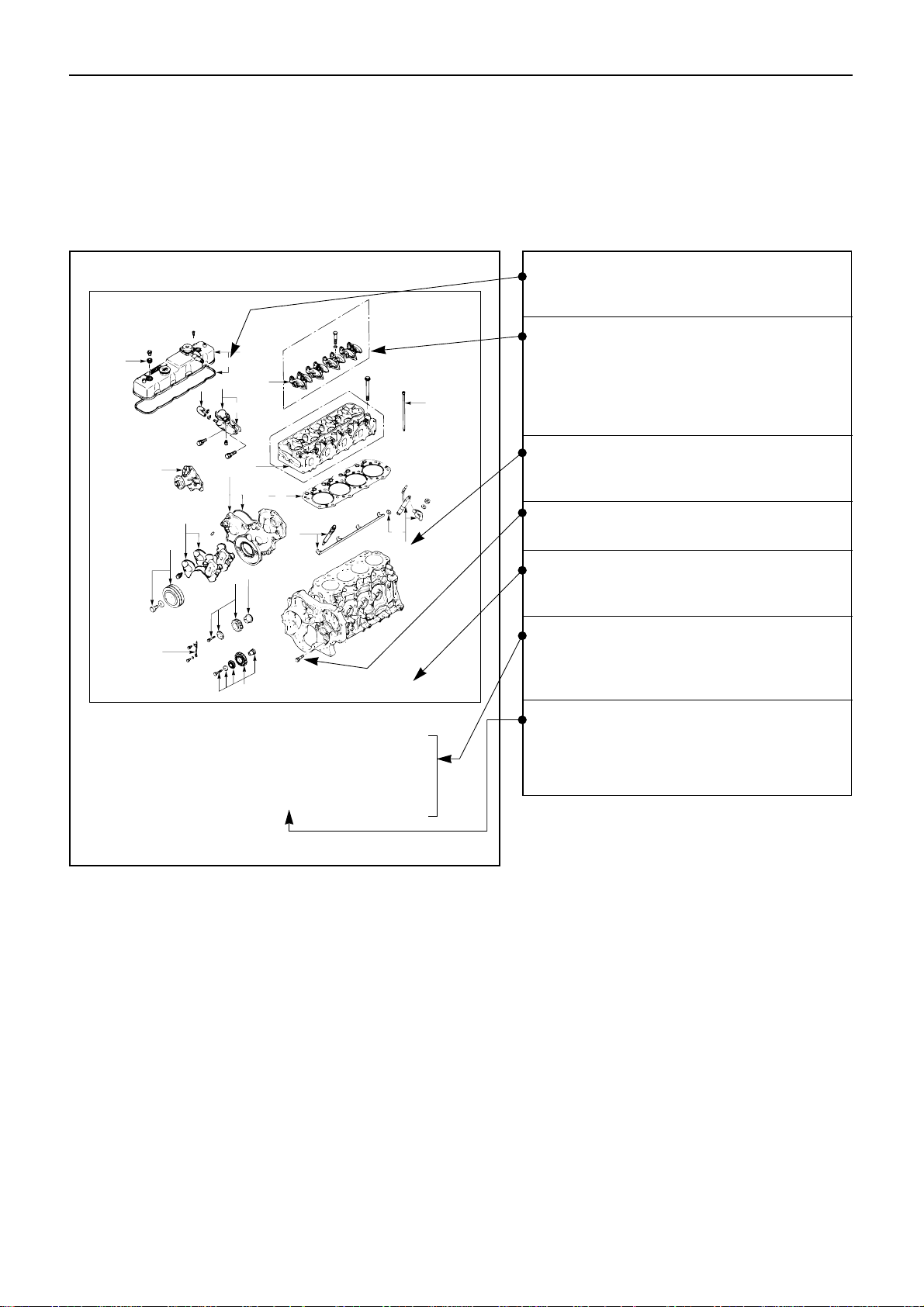
More complex procedures are covered in detail.
6. Each service operation section in this Workshop Manual begins with an exploded view of the
applicable area. A brief explanation of the notation used follows.
15
14
16
17
11
12
13
3
9
10
5
4
8
7
6
2
1
★
★Repair kit
★
★
★
★
★
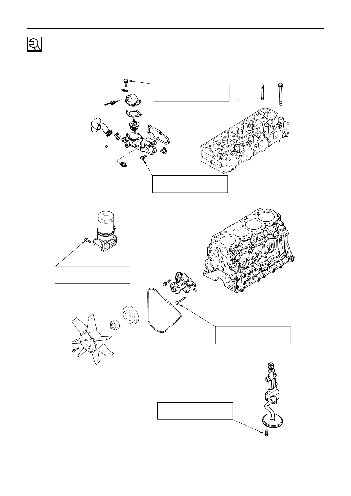
Disassembly Steps - 2
1. Water by-pass hose
2. Thermostat housing
3. Water pump
▲ 4. Injection nozzle holder
5. Glow plug and glow plug connector
6. Cylinder head cover
▲ 7. Rocker arm shaft and rocker arm
8. Push rod
▲ 9. Cylinder head
10. Cylinder head gasket
▲ 11. Crankshaft damper pulley with
dust seal
12. Timing gear case cover
13. Timing gear cover
14. Timing gear oil pipe
15. Idler gear “B” and shaft
▲ 16. Idler gear “A”
17. Idler gear shaft
Inverted Engine
Parts marked with an asterisk (*) are
included in the repair kit.
Parts within a square frame are to be
removed and installed as a single unit,
and their disassembly steps or reassembly steps are shown in the
illustrations respectively.
The number tells you the service operation sequence.
Removal of unnumbered parts is unnecessary unless replacement is required.
The "* Repair Kit" indicates that a repair
kit is available.
The parts listed under "Disassembly
Steps" or "Reassembly Steps" are in the
service operation sequence.
The removal or installation of parts
marked with a triangle (▲) is an
important operation. Detailed information is given in the text.
Page 7
GENERAL INFORMATION
4
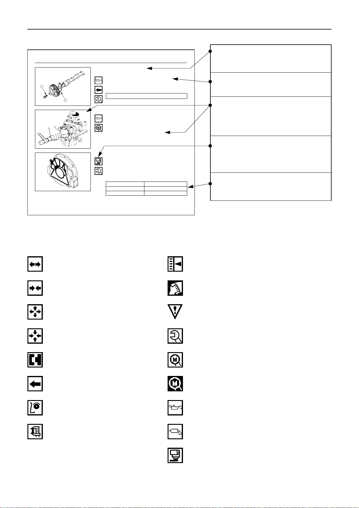
8. The following symbols appear throughout this Workshop Manual. They tell you the type of service
operation or step to perform.
.... Removal .... Adjustment
.... Installation .... Cleaning
.... Disassembly ... Important operation requiring extra care
.... Reassembly .... Specified torque (tighten)
.... Alignment (marks) ....
Special tool use required or
recommended(Isuzu tool or tools)
.... Directional indication ....
Commercially available tool use
required or recommended
.... Inspection .... Lubrication (oil)
.... Measurement .... Lubrication (grease)
.... Sealant application
7. Below is a sample of the text of the Workshop Manual.
4. Camshaft Timing Gear
1) Install the thrust plate 1 .
2) Apply engine oil to the bolt threads 2 .
3) Install the camshaft timing gear with the timing
mark stamped side facing out.
Camshaft Timing Gear Bolt Torque kgf·m(lb.ft/N·m)
11.0 ± 1.0 (79.5 ± 7.2/107.8 ± 9.8)
1
2
13. Crankshaft Rear Oil Seal
1) Apply engine oil to the oil seal lip circumference
and the oil seal outer circumference.
2) Use the oil seal installer to install the oil seal to
the cylinder body.
Oil Seal Installer: 5-8840-0141-0
14. Flywheel Housing
1) Apply liquid gasket to the shaded area shown in
the illustration.
2) Tighten the flywheel housing bolts to the specified torque a little at a time in the sequence
shown in the illustration.
Flywheel Housing Bolt Torque kgf·m(lb.ft/N·m)
M10x1.25 (0.40x0.05) Bolt 5.6±1.0 (40.5±7.2/ 54.9±9.8)
M12x1.25 (0.47x0.05) Bolt 10.5±1.0 (76.0±7.2/103.0±9.8)
M12x1.75 (0.47x0.07) Bolt 9.8±1.0 (71.0±7.2/ 96.0±9.8)
7
4
8
6
10
9
3
2
1
5
This is the item shown in the illustration. It is marked with a triangle
(▲) on the Major Components page.
Letters and numbers contained in a
circle refer to the illustration.
Special tools are identified by the
tool name and/or number.
The illustration shows how the special tool is to be used.
Symbols indicate the type of service
operation or step to be performed. A
detailed explanation of these
symbols follows.
Service data and specifications are
given in this table.
Page 8

GENERAL INFORMATION
9. Measurement criteria are defined by the terms "standard" and "limit".
A measurement falling within the "standard" range indicates that the applicable part or parts are
serviceable.
"Limit" should be thought of as an absolute value.
A measurement which is outside the "limit" indicates that the applicable part or parts must be either
repaired or replaced.
10. Components and parts are listed in the singular form throughout the Manual.
11. Directions used in this Manual are as follows:
Front
The cooling fan side of the engine viewed from the flywheel.
Right
The right hand side viewed from the same position.
Left
The left hand side viewed from the same position.
Rear
The flywheel side of the engine.
Cylinder numbers are counted from the front of the engine.
The front most cylinder is No. 1 and rear most cylinder is the final cylinder number of the engine.
The engine's direction of rotation is counterclockwise viewed from the flywheel.
5
Page 9
GENERAL INFORMATION
MAIN DATA AND SPECIFICATIONS
6
Engine Model
A-4JA1 A-4JB1 4JB1T
Item
Engine type Water cooled, four-cycle, in-line, overhead valve
Combustion chamber type Direct injection
Cylinder liner type Dry
No. of cylinders - Bore x Stroke mm(in.) 4 - 93.0 x 92.0 4 - 93.0 x 102.0 4 - 93.0 x 102.0
(3.66 x 3.62) (3.66 x 4.02) (3.66 x 4.02)
Total piston displacement lit(cid) 2.449 (152.4) 2.771 (169.0) 2.771 (169.0)
Compression ratio (To 1) 18.4 18.2 18.2
*Engine dimensions mm(in.) 805 x 625 x 729 739 x 625 x 746 578 x 771 x 577
Length x Width x Height (31.7 x 24.6 x 28.7) (29.1 x 24.6 x 29.4) (22.8 x 30.4 x 22.7)
*Engine weight (Dry) kg(lb.) 218 (480) 220 (486) 245 (540)
Fuel injection order 1 – 3– 4 – 2
*Fuel injection timing (B.T.D.C.) degrees 14
Specified fuel Diesel fuel
Injection pump In-line plunger, Bosch A type Bosch distributor
VE type
Governor Variable speed mechanical type
*Low idle speed rpm 850 – 1,000
Injection nozzle Multi-hole type
Injection starting pressure kgf/cm2(psi/MPa) 185 (2630/18.1)
Fuel filter type Cartridge papaer element
Water sedimentor (if so equipped) Sediment/water level indicating type
Compression pressure kgf/cm2(psi/MPa) 31 (441/3.04)
Valve clearance (at cold) Intake mm(in.) 0.40 (0.0157)
Exhaust mm(in.) 0.40 (0.0157)
Lubrication method Pressurized circulation
Oil pump Trochoid type
Main oil filter type Cartridge paper element, full flow
Partial oil filter Not equipped
*Lubricating oil volume lit.(qts) 5.5 (5.8) – 6.6 (7.0) 4.6 (4.9) – 6.4 (6.8) 4.6 (4.9) – 6.3 (6.7)
Oil cooler (if so equipped) Water cooled built in oil filter
Cooling method Pressurized forced circulation
Coolant volume lit.(qts) 5.0 (5.3)
Water pump Belt driven impeller type
Thermostat type Wax pellet type
*Alternator V-A 12 – 35
*Starter V-kW 12 – 2.2
Specifications marked with an asterisk (*) will vary according to engine application.
Page 10
GENERAL INFORMATION
7
TIGHTENING TORQUE SPECIFICATIONS
The tightening torque values given in the table below are applicable to the bolts unless otherwise
specified.
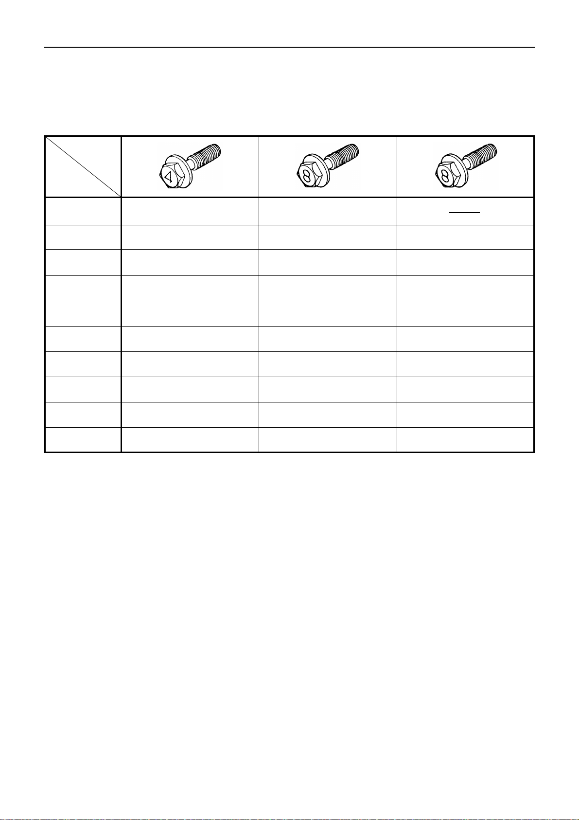
STANDARD BOLT kgf·m (lb.ft/N·m)
An asterisk (*) indicates that the bolts are used for female threaded parts that are made of soft materials
such as casting. Those shown in parentheses in the strength class indicate the classification by the old
standard.
M 6 × 1.0
M 8 × 1.25
M10 × 1.25
M12 × 1.25
M14 × 1.5
M16 × 1.5
M18 × 1.5
M20 × 1.5
M22 × 1.5
M24 × 2.0
*M10 × 1.5
*M12 × 1.5
*M14 × 2.0
*M16 × 2.0
0.4 – 0.8
(2.9 – 5.8/3.9 – 7.8)
0.8 – 1.8
(5.8
–
13.0/7.8– 17.7)
2.1 – 3.5
(15.2– 25.3/20.6– 34.3)
5.0
–
7.5
(36.2
–
54.2/49.0– 73.6)
7.8
–
11.7
(56.4
–
84.6/78.5– 114.7)
10.6
–
16.0
(76.7
–
115.7/103.0– 156.9)
15.4
–
23.0
(111.1
–
166.4/151.0– 225.6)
21.0
–
31.6
(151.9
–
228.6/205.9– 307.9)
25.6
–
42.2
(185.2
–
305.2/251.1– 413.8)
36.6
–
55.0
(264.7
–
397.8/358.9– 539.4)
2.0
–
3.4
(14.5
–
24.6/19.6– 32.4)
4.6
–
7.0
(33.3
–
50.6/45.1– 68.7)
7.3
–
10.9
(52.8
–
78.8/71.6– 106.9)
10.2
–
15.2
(73.8
–
110.0/100.0– 149.1)
0.5
–
1.0
(3.6
–
7.2/4.9– 9.8)
1.2
–
2.3
(8.7
–
16.6/11.8– 22.6)
2.8
–
4.7
(20.3
–
34.0/27.5– 46.1)
6.2
–
9.3
(44.8
–
67.3/60.8– 91.2)
9.5
–
14.2
(68.7
–
102.7/93.2– 139.3)
13.8
–
20.8
(99.8
–
150.4/135.3– 204.0)
19.9
–
29.9
(143.9
–
216.3/195.2– 391.3)
27.5
–
41.3
(198.9
–
298.7/269.7– 405.0)
37.0
–
55.5
(267.6
–
401.4/362.9– 544.3)
43.9
–
72.5
(317.5
–
523.9/430.5– 711.0)
2.8
–
4.6
(20.3
–
33.3/27.5– 45.1)
5.8
–
8.6
(42.0
–
62.2/56.9– 84.3)
9.0
–
13.4
(65.1
–
96.9/88.3– 131.4)
13.2
–
19.8
(95.5
–
143.2/129.5 – 194.2)
1.7
–
3.1
(12.3
–
22.4/16.7– 30.4)
3.8
–
6.4
(27.5
–
46.3/37.3– 62.8)
7.7
–
11.6
(55.7
–
83.9/75.5– 113.8)
11.6
–
17.4
(83.9
–
125.6/113.8– 170.6)
16.3
–
24.5
(118.9
–
177.2/159.9– 240.3)
23.4
–
35.2
(169.3
–
254.6/229.5– 345.2)
32.3
–
48.5
(233.6
–
350.8/316.8– 475.6)
43.3
–
64.9
(313.2
–
469.4/424.6– 636.5)
56.5
–
84.7
(408.7
–
612.6/554.1– 830.6)
3.7
–
6.1
(26.8
–
44.1/36.3– 59.8)
7.3
–
10.9
(52.8
–
78.8/71.6– 106.9)
10.9
–
16.3
(78.8
–
118.9/106.9– 159.9)
15.6
–
23.4
(112.8
–
169.3/162.8– 229.5)
Refined
No mark
Non-Refined
4.8 (4T)
8.8(7T)
9.8 (9T)
Strength
Class
Bolt
Identification
Bolt
Diameter ×
pitch (mm)
Page 11
GENERAL INFORMATION
8
TIGHTENING TORQUE SPECIFICATIONS
The tightening torque values given in the table below are applicable to the bolts unless otherwise
specified.
FLANGED HEAD BOLT kgf·m (lb.ft/N·m)
M 6 × 1
0.5– 0.9 0.6 – 1.2
(3.61– 6.50/4.6
–
8.5 (4.33 – 8.67/5.88 – 11.76)
M 8 × 1.25
1.1
–
2.0 1.4
–
2.9 1.9– 3.4
(7.95– 14.46/10.78– 19.61) (4.33– 8.67/5.88– 11.76) (13.74– 24.59/18.63– 33.34)
M10 × 1.25
2.3
–
3.9 3.6– 6.4 4.3– 7.2
(17.35– 28.20/23.53– 38.24) (26.03– 44.12/35.30– 59.82) (31.10– 52.07/42.16– 70.60)
*M10 × 1.5
2.3
–
3.8 3.5– 5.8 4.1– 6.8
(16.63
–
27.48/22.55– 37.26) (25.31– 41.95/34.32– 56.87) (29.65– 49.18/40.20– 66.68)
M12 × 1.25
5.6– 8.4 7.9– 11.9 8.7– 13.0
(40.50
–
60.75/54.91– 82.37) (57.14– 86.07/77.47– 116.69) (62.92– 94.02/85.31– 127.48)
*M12 × 1.75
3.5
–
9.5 7.3– 10.9 8.1– 12.2
(37.61– 56.41/50.99– 76.49) (52.80– 78.83/71.58– 106.89) (58.58– 88.24/79.43– 119.64)
M14 × 1.5
8.5
–
12.7 11.7– 17.6 12.6– 18.9
(61.48
–
91.85/83.35– 124.54) (84.62– 127.30/114.73– 172.59) (91.13– 136.70/123.56– 185.34)
*M14 × 2
7.6– 11.5 11.1– 16.6 11.8– 17.7
(57.14
–
85.34/77.47– 115.71) (80.28– 120.06/108.85– 162.79) (85.34– 128.02/115.71– 173.57)
M16 × 1.5
11.8– 17.7 17.1
–
26.5 18.0
–
27.1
(85.34
–
128.02/115.71– 173.57) (125.85– 189.50/170.63– 256.93) (130.19– 196.01/176.52– 265.76)
*M16 × 2
11.2– 16.7 16.6– 24.9 17.2– 25.7
(81.00
–
120.79/109.83
–
163.77) (120.06
–
180.10/162.79– 244.18) (124.40– 186.61/168.67– 253.01)
A bolt with an asterisk (*) is used for female screws of soft material such as cast iron.
Bolt head
marking
Nominal
size
(dia. x pitch)
Page 12
GENERAL INFORMATION
9
SPECIAL PARTS FIXING NUTS AND BOLTS
Cylinder Head Cover, Cylinder Head, and Rocker Arm Shaft Bracket
kgf·m(lb.ft./N·m)
1.0 – 2.0
(7.2 – 14.4/9.8 – 19.6)
0.8 – 1.8
(5.8 – 13.0/7.8 – 17.6)
1st Step 2nd Step
3.0 – 5.0
(21.7 – 36.1/29.4 – 49.0)
8.2 – 9.2
(59.4 – 66.5/80.4 – 90.2)
8.0 – 9.0
(57.9 – 65.1/78.4 – 88.2)
10.0 – 11.0
(72.4 – 79.6/98.1 – 107.9)
5.0 – 6.0
(36.2 – 43.4/49.0 – 58.8)
New bolt
Reused
bolt
Page 13
GENERAL INFORMATION
10
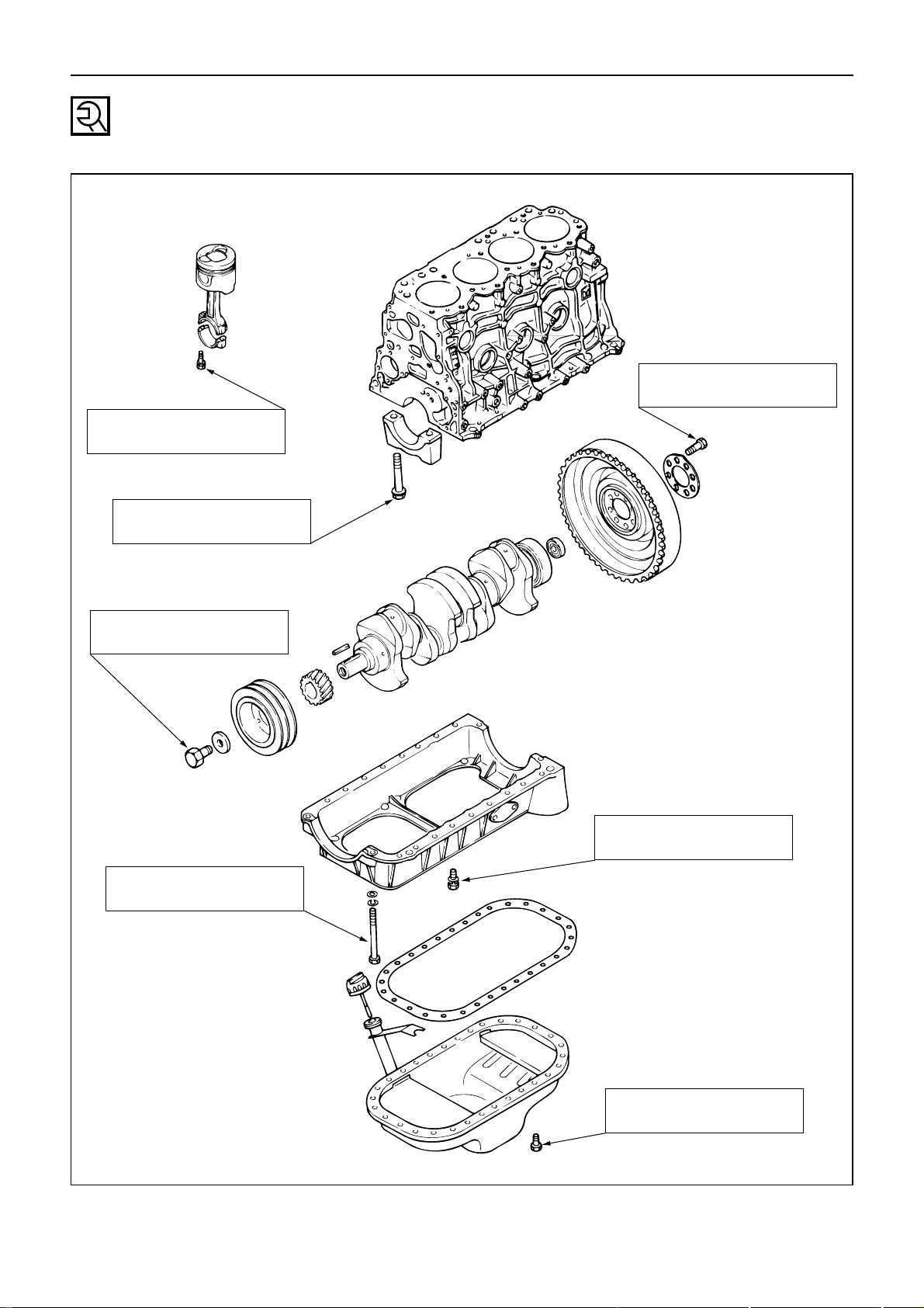
Crankshaft Bearing Cap, Connecting Rod Bearing Cap,
Crankshaft Damper Pulley, Flywheel, and Oil Pan
kgf·m(lb.ft./N·m)
8.0 – 9.0
(57.9 – 65.1/78.4 – 88.2)
16.0 – 18.0
(115.7 – 130.2/159.6 – 176.5)
20.1 – 24.5
(145.4 – 177.2/197.1 – 240.3)
1.4 – 2.4
(10.1 – 17.3/13.7 – 23.5)
1.4 – 2.4
(10.1 – 17.3/13.7 – 23.5)
11.5 – 12.5
(83.2 – 90.4/112.8 – 122.6)
14 – 24
(1.4 – 2.4/4.4 – 7.2)
Page 14
GENERAL INFORMATION
11
Timing Gear Case, Flywheel Housing, Camshaft, and Timing Gear
kgf·m(lb.ft./N·m)
1.4 – 2.4
(10.1 – 17.3/13.7 – 23.5)
1.4 – 2.4
(10.1 – 17.3/13.7 – 23.5)
10.0 – 12.0
(72.4 – 86.8/98.1 – 117.7)
1.4 – 2.4
(10.1 – 17.3/13.7 – 23.5)
1.4 – 2.4
(10.1 – 17.3/13.7 – 23.5)
1.0 – 1.5
(7.2 – 10.9/9.8 – 14.7)
6.6 – 8.7
(48 – 63/66 – 85)
M10 x 1.25 (0.39 x 0.05) 4.6 – 6.6 (33.3 – 47.7/45.1 – 64.7)
9.6 – 11.6 (69.4 – 83.9/94.1 – 113.8)
8.8 – 10.8 (63.7 – 78.1/86.3 – 105.9)
M12 x 1.25 (0.47 x 0.05)
M12 x 1.75 (0.47 x 0.07)
Page 15
GENERAL INFORMATION
12
Cooling and Lubricating System
kgf·m(lb.ft./N·m)
1.4 – 2.4
(10.1 – 17.3/13.7 – 23.5)
1.4 – 2.4
(10.1 – 17.3/13.7 – 23.5)
1.4 – 2.4
(10.1 – 17.3/13.7 – 23.5)
1.4 – 2.4
(10.1 – 17.3/13.7 – 23.5)
1.4 – 2.4
(10.1 – 17.3/13.7 – 23.5)
Page 16
GENERAL INFORMATION
13
Intake and Exhaust Manifold
kgf·m(lb.ft./N·m)
1.4 – 2.4
(10.1 – 17.3/13.7 – 23.5)
1.4 – 2.4
(10.1 – 17.3/13.7 – 23.5)
Page 17
GENERAL INFORMATION
14
Engine Electrical
kgf·m(lb.ft./N·m)
1.4 – 2.4
(10.1 – 17.3/13.7 – 23.5)
3.6 – 4.6
(26.0 – 33.3/35.3 – 45.1)
2.0 – 2.5
(14.4 – 18.1/19.6 – 24.5)
6.0 – 8.0
(43.4 – 57.9/58.8 – 78.4)
Page 18
GENERAL INFORMATION
15
Fuel Injection System
kgf·m(lb.ft./N·m)
3.2 – 4.4
(23.1 – 31.8/31.4 – 43.2)
20 – 4.0
(14.4 – 28.9/19.6 – 39.2)
1.4 – 2.4
(10.1 – 17.3/13.7 – 23.5)
1.4 – 2.4
(10.1 – 17.3/13.7 – 23.5)
1.4 – 2.4
(10.1 – 17.3/13.7 – 23.5)
1.4 – 2.4
(10.1 – 17.3/13.7 – 23.5)
1.4 – 2.4
(10.1 – 17.3/13.7 – 23.5)
Page 19

16
MEMO
Page 20

MAINTENANCE
17
SECTION 2
MAINTENANCE
TABLE OF CONTENTS
ITEM PAGE
Model identification ............................................................. 18
Injection pump identification ...................................................... 18
Lubricating system .............................................................. 18
Fuel system .................................................................... 19
Cooling system ................................................................. 22
Valve clearance adjustment ....................................................... 23
Injection timing ................................................................. 24
Compression pressure measurement ............................................... 26
Recommended lubricants ......................................................... 27
Engine repair kit ................................................................ 28
Page 21
MAINTENANCE
MAINTENANCE
Servicing refers to general maintenance procedures to be performed by qualified service personnel.
Maintenance interval such as fuel or oil filter changes should be refered to “INSTRUCTION MANUAL”.
MODEL IDENTIFICATION
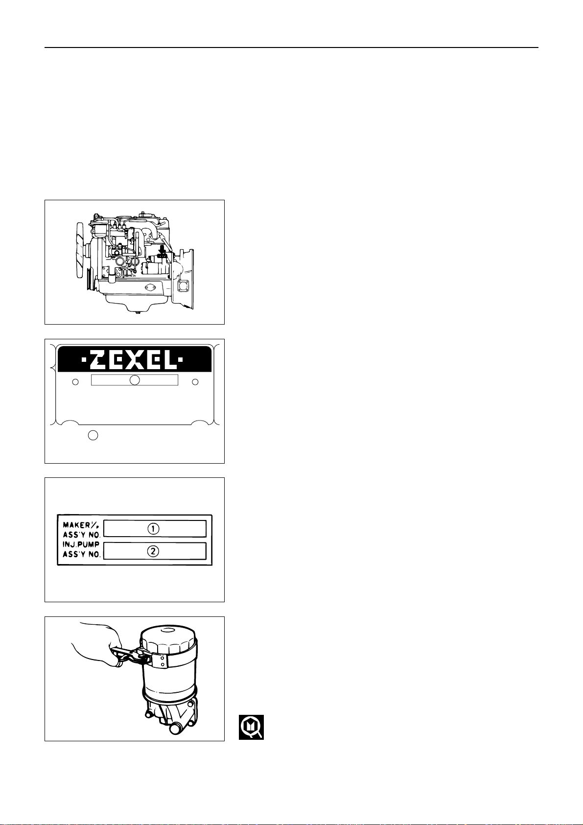
Engine Serial Number
The engine number is stamped on the rear left hand side
of the cylinder body.
INJECTION PUMP IDENTIFICATION
Injection volume should be adjusted after referring to
the adjustment data applicable to the injection pump
installed.
The injection pump identification number (A) is stamped
on the injection pump identifications plate.
Note:
Always check the identification number before beginning a service operation.
Applicable service data will vary according to the identification number. Use of the wrong service data will
result in reduced engine performance and engine
damage.
1 ZEXEL (Manufacturer of the injection pump) identifi-
cation number
2 ISUZU Parts Number
Pump No. . . . . . . . . . . . . . .
NP - PE . . . . . . . . . . . . . . . . . . . . . .
(LICENCE BOSCH)
A
A
…Identification number
In-line type
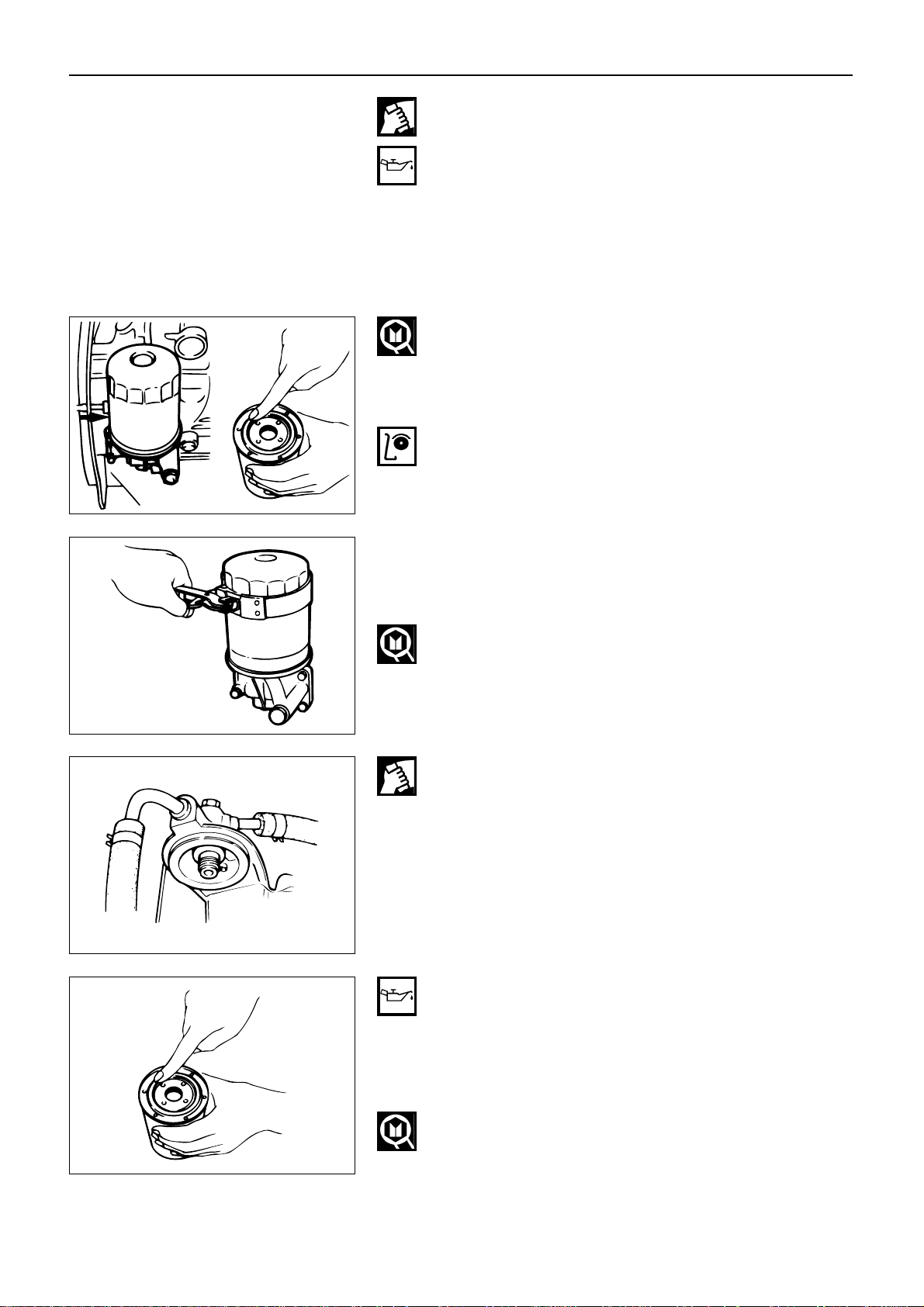
LUBRICATING SYSTEM
Main Oil Filter
Replacement Procedure
1. Loosen the drain plug to drain the engine oil.
2. Wait a few minutes and then retighten the drain
plug.
3. Loosen the used oil filter by turning it counterclockwise with a filter wrench.
Filter Wrench
18
Distributor type
Page 22
MAINTENANCE
4. Clean the oil cooler fitting face.
This will allow the new oil filter to seat properly.
5. Apply a light coat of engine oil to the O-ring.
6. Turn in the new oil filter until the filter O-ring is
fitted against the sealing face.
7. Use a filter wrench to turn in the filter an additional
1 and 1/4 of a turn.
Filter Wrench
8. Check the engine oil level and replenish to the specified level if required.
9. Start the engine and check for oil leakage from the
main oil filter.
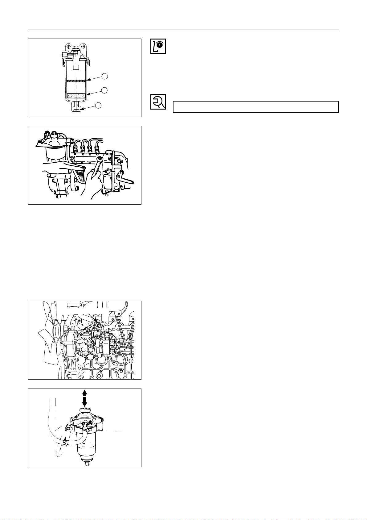
FUEL SYSTEM
Fuel Filter
Replacement Procedure
1. Loosen the used fuel filter by turning it counterclockwise with the filter wrench.
Filter Wrench
2. Clean the upper cover fitting face.
This will allow the new fuel filter to seat properly.
3. Apply a light coat of engine oil to the O-ring.
4. Supply fuel to the new fuel filter to facilitate bleeding.
5. Turn in the new fuel filter until the filter O-ring is fitted against the sealing face.
Be very careful to avoid fuel spillage.
6. Use a filter wrench to turn in the fuel filter an additional 1/3 to 2/3 of a turn.
19
Page 23
MAINTENANCE
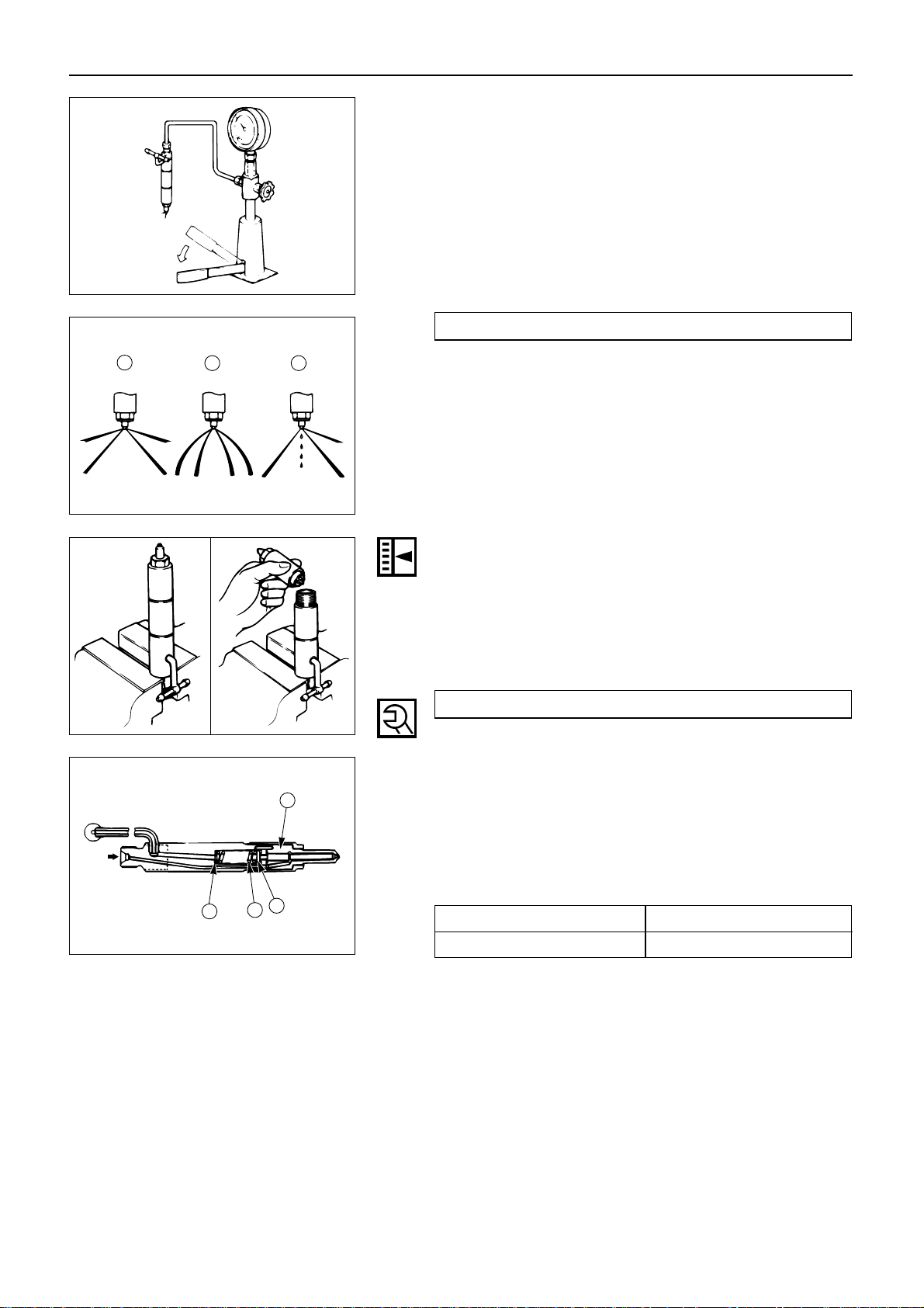
Water Separator (Water Sedimentor)
(Optional Equipment)
Check the water separator float 1 level.
If the float 1 has reached level 2 , loosen the drain plug
3 (at the bottom side of the water separator) to drain
the water.
Drain Plug Torque kgf·m(lb.ft./N·m)
0.9 – 1.5 (6.5 – 10.9/8.8 – 14.7)
1
2
3
Air Bleeding
1. For the engine equipped with in-line type injection
pump
1) Loosen the priming pump cap 1 on the injection
pump.
2) Loosen the fuel return eye bolt 2 on the fuel filter.
3) Operate the priming pump until there are no more
bubbles visible in the fuel being discharged from the
fuel return eye bolt on the fuel filter.
4) Retighten the fuel return eye bolt on the fuel filter.
5) Loosen the bleeder bolt 3 while operating the
injection pump priming pump to check that the air
has been bled completely.
6) Operate the priming pump several times to check for
fuel leakage around the injection pump and the fuel
filter.
2. For the engine equipped with distributor type injection pump
1) Loosen the bleeder screw on the injection pump
overflow valve.
2) Operate the priming pump until fuel mixed with
foam flows from the bleeder screw.
3) Tighten the bleeder screw.
4) Operate the priming pump several times and check
for fuel leakage.
20
080ES004
Air bleeding screw
Page 24
MAINTENANCE
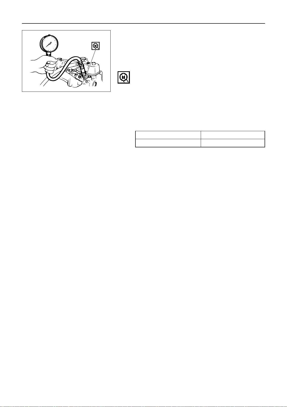
Injection Nozzle
Injection Nozzle Inspection
Use a nozzle tester to check the injection nozzle opening
pressure and the spray condition.
If the opening pressure is above or below the specified
value, the injection nozzle must be replaced or reconditioned.
If the spray condition is bad, the injection nozzle must be
replaced or reconditioned.
Injection Nozzle Opening Pressure kgf/cm2(psi/MPa)
185 (2,630/18.1)
Spray Condition
(1) Correct
(2) Incorrect (Restrictions in orifice)
(3) Incorrect (Dripping)
Injection Nozzle Adjustment
1. Clamp the injection nozzle in a vise.
2. Use a wrench to remove the injection nozzle retaining nut.
3. Install the injection nozzle 1 , the push rod 2 , the
spring 3 , and adjusting shim 4.
Retaining Nut Torque kgf·m(lb.ft./N·m)
4.0 – 5.0 (28.9 – 36.2/39.2 – 49.0)
4. Attach the injection nozzle holder to the injection
nozzle tester.
5. Apply pressure to the nozzle tester to check that the
injection nozzle opens at the specified pressure.
If the injection nozzle does not open at the specified
pressure, install or remove the appropriate number
of adjusting shims to adjust it.
Adjusting Shim Availability mm(in.)
Range 0.50 – 1.50 (0.02 – 0.06)
Increment 0.025 (0.001)
Total No. of Shims 40
(Reference)
Removing or installing one shim will increase or
decrease the nozzle opening pressure approximately
3.77 kgf/cm2(53.6 psi/370kPa).
WARNING:
TEST FLUID FROM THE INJECTION NOZZLE TESTER
WILL SPRAY OUT UNDER GREAT PRESSURE. IT CAN
EASILY PUNCTURE A PERSON’S SKIN. KEEP YOUR
HANDS AWAY FROM THE INJECTION NOZZLE TESTER
AT ALL TIMES.
21
1
2 3
1
2
3
4
Page 25
MAINTENANCE
COOLING SYSTEM
Cooling Fan Drive Belt
Fan belt tension is adjusted by moving the alternator.
A Crankshaft damper pulley
B Alternator pulley
C Cooling fan drive pulley
D Depress the drive belt mid-portion with a 10 kgf (22
lb/98 N) force.
Drive Belt Deflection mm(in.)
10.0 (0.39)
A
C
D
B
Thermostat
Operating Test
1. Completely submerge the thermostat in water.
2. Heat the water.
Stir the water constantly to avoid direct heat being
applied to the thermostat.
3. Check the thermostat initial opening temperature.
Thermostat Initial Opening Temperature °C(°F)
82 (180)
4. Check the thermostat full opening temperature.
Thermostat Full Opening Temperature °C(°F)
95 (203)
Valve Lift at Fully Open Position mm(in.)
8.0 (0.315)
1 Thermostat
2 Agitating Rod
3 Wooden Piece
1
2
3
22
Page 26
MAINTENANCE
VALVE CLEARANCE ADJUSTMENT
1. Retighten the rocker arm shaft bracket bolts in
sequence as shown in the illustration.
Rocker Arm Shaft Bracket Bolt
Torque kgf·m(lb.ft/N·m)
5.0 – 6.0 (36.2 – 43.4/49.0 – 58.8)
3124
2. Bring the piston in either the No. 1 cylinder or the
No. 4 cylinder to TDC on the compression stroke by
turning the crankshaft until the crankshaft damper
pulley TDC line is aligned with the timing pointer.
TDC
3. Check for play in the No. 1 intake and exhaust valve
push rods.
If the No. 1 cylinder intake and exhaust valve push
rods have play, the No. 1 piston is at TDC on the
compression stroke.
If the No. 1 cylinder intake and exhaust valve push
rods are depressed, the No. 4 piston is at TDC on the
compression stroke.
Adjust the No. 1 or the No. 4 cylinder valve clearances
while their respective cylinders are at TDC on the compression stroke.
Valve Clearance mm(in.)
0.40 (0.016)
Loosen each valve clearance adjusting screw as shown
in the illustration. (At TDC on the compression stroke of
the No. 1 cylinder)
Insert a feeler gauge of the appropriate thickness
between the rocker arm and the valve stem end.
4. Turn the valve clearance adjusting screw until a
slight drag can be felt on the feeler gauge.
5. Tighten the lock nut securely.
23
Page 27
MAINTENANCE
Rotate the crankshaft 360°.
Realign the crankshaft damper pulley TDC line with the
timing pointer.
Adjust the clearances for the remaining valves as shown
in the illustration. (At TDC on the compression stroke of
the No. 4 stroke)
INJECTION TIMING
Injection Timing Confirmation Procedure
1. In-line type injection pump
1) Rotate the crankshaft clockwise to align the cam shaft gear timing mark “O” with the timing gear
case cover pointer.
The No. 1 cylinder will now be at the point where
nearly injection timing.
2) Remove the No. 1 fuel injection pipe.
3) Remove the delivery valve holder 1 , the delivery
valve spring 2 , and the delivery valve 3 .
4) Tighten the delivery valve holder to the specified
torque.
Delivery Valve Holder Torque kgf·m(lb.ft/N·m)
4.0 – 4.5 (28.9 – 32.5/39.2 – 44.1)
1
2
3
5) Operate the injection pump priming pump while
slowly rotating the crankshaft until fuel stops flowing from the delivery valve holder.
6) Conform that the crankshaft damper pulley notched
line is aligned with the timing gear case cover
pointer.
Injection Timing (Static BTDC)
14°
TDC 17
24
7) Remove the delivery valve holder.
8) Install the delivery valve 1 , the delivery valve
spring 2 , and the delivery valve holder 3 .
9) Tighten the delivery valve holder to the specified
torque.
10) Install the fuel injection pipes and tighten them to
the specified torque.
Fuel Injection Pipe Torque kgf·m(lb.ft/N·m)
2.0 – 4.0 (14.4 – 28.9/19.6 – 39.2)
11) Operation to air breeding.
1
2
3
Page 28
MAINTENANCE
25
2. Distributor type injection pump
1) Rotate the crankshaft clockwise to align the cam shaft gear timing mark “O” with the timing gear
case cover pointer.
The No. 1 cylinder will now be at the point where
nearly injection timing.
2) Remove injector pump distributor head plug.
3) Fit a dial gauge and set lift to 1 mm (0.039 in).
4) Set crankshaft damper pulley Top Dead Center mark
about 45° before Top Dead Center from the pointer.
5) Set dial gauge in the “0” position.
Measuring device: 5-8840-0145-0
6) Turn the crankshaft a little rightwise and leftwise
and see if the pointer is stable in the “0” position.
7) Turn the crankshaft in the normal direction and read
the measuring device’s indication at TDC.
Starting Timing mm(in.)
0.5 (0.02)
8) If the injection timing is outside the specified range,
continue with the following steps.
9) Loosen the injection pump fixing nuts and bracket
bolts.
10) Adjust the injection pump setting angle.
• If injection timing will be advanced, move the
injection pump away from the engine.
• If injection timing will be retarded, move the
injection pump toward the engine.
Tighten the pump fixing nut, adjust bolt and pump
distribution head plug to the specified torque.
Pump Fixing Bolt kgf·m(lb.ft/N·m)
1.9 (13.7/18.6)
Injection Pump
Distributor Head Plug kgf·m(lb.ft/N·m)
1.7 (12.3/16.7)
080ES002
080ES003
Page 29
MAINTENANCE
26
4. Set a compression gauge to the No. 1 cylinder glow
plug hole.
5. Turn the engine over with the starter motor and take
the compression gauge reading.
Compression Pressure kgf/cm2(psi/MPa) at 200 rpm
Standard Limit
31 (441/3.04) 22 (313/2.157)
COMPRESSION PRESSURE MEASUREMENT
1. Start the engine and allow it to run for several
minutes to warm it up.
2. Stop the engine and cut the fuel supply.
3. Remove all of the glow plugs from the engine.
Compression Gauge :5-8840-2675-0
Adapter :5-8840-9029-0
Page 30

MAINTENANCE
27
RECOMMENDED LUBRICANTS
ENGINE TYPE TYPES OF LUBRICANTS
Diesel engine oil
Without turbocharger
CC or CD grade
Diesel engine oil
With turbocharger
CD grade
ENGINE OIL VISCOSITY CHART
ENGINE OIL VISCOSITY GRADE – AMBIENT TEMPERATURE
[Single grade]
–0°C
(32°F)
15°C
(59°F)
25°C
(77°F)
30°C
(86°F)
–15°C
(5°F)
–30°C
(–22°F)
[Multi grade]
SAE 40
SAE 20, 20W
SAE 10W–30
SAE 15W–40, 20W–40
SAE 30
Ambient
Temperature
SAE 10W
Page 31

MAINTENANCE
28
ENGINE REPAIR KIT
All of the numbered parts listed below are included in the Engine Repair Kit.
The gaskets marked with an asterisk (*) are also included in the Top Overhaul Kit.
3
15
13
12
2
17
18
14
1
11
7
16
8
9
4
19
6
10
19
20
19
5
* 1. Cylinder head gasket
* 2. Cylinder head cover gasket
* 3. Head cover cap nut gasket
4. Drain cock gasket
5. Crankshaft rear oil seal
6. Gear case gasket
7. Gear case cover gasket
8. Oil pan drain plug gasket
9. Oil pan gasket
10. Oil filter gasket
11. Water pump gasket
12. Water outlet pipe gasket
* 13. Thermostat housing gasket
* 14. Intake manifold gasket
* 15. Exhaust manifold gasket
16. Crankshaft front oil seal
* 17. Nozzle holder O-ring
* 18. Nozzle holder gasket
19. Joint bolt gasket
20. Vacuum pump pipe gasket
Page 32

ENGINE ASSEMBLY ( 1 )
29
SECTION 3
ENGINE ASSEMBLY ( 1 )
TABLE OF CONTENTS
ITEM PAGE
General description .............................................................. 30
Disassembly .................................................................... 31
Page 33

ENGINE ASSEMBLY ( 1 )
ENGINE ASSEMBLY
GENERAL DESCRIPTION
This illustration is based on the A-4JA1 engine.
30
The A-4J Series of industrial engines features the unique ISUZU troidal square combustion chamber. This
design provides superior fuel economy for a wide range.
Auto-thermatic pistons with cast steel struts are used to reduce thermal expansion and resulting engine
noise when the engine is cold.
Chrome plated dry type cylinder liners provide the highest durability.
The laminated steel sheet cylinder head gasket is very durable.
This type of gasket eliminates cylinder head bolt retightening.
The tufftrided crankshaft has a long service life. Because it is tufftrided, it cannot be reground.
The crankshaft main bearings and the connecting rod bearings are aluminum plated. These bearings are
especially sensitive to foreign material such as metal scraps. It is very important that the oil ports and
other related parts be kept clean and free of foreign material.
Page 34

ENGINE ASSEMBLY ( 1 )
DISASSEMBLY
These disassembly steps are based on the A-4JA1 engine.
31
Disassembly Steps - 1
1. Cooling fan and spacer
2. Cooling fan drive belt
3. Cooling fan drive pulley
4. Alternator and adjusting plate
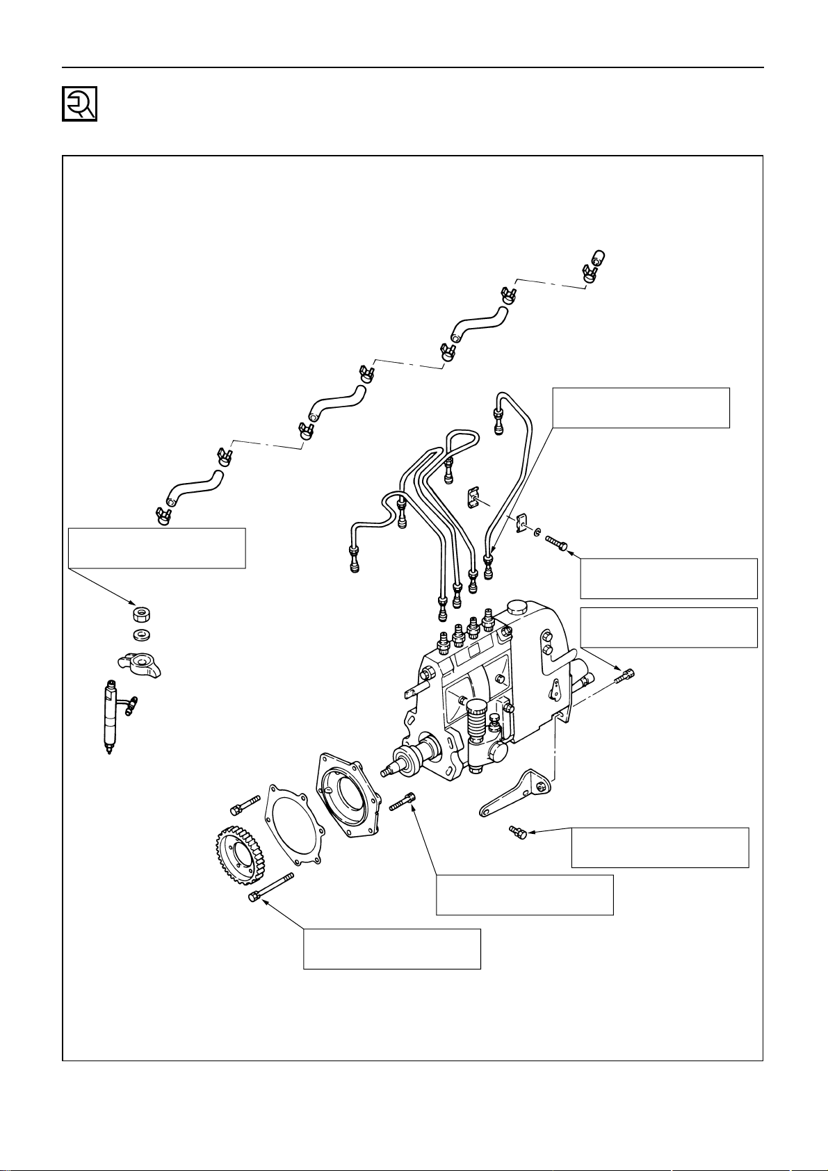
5. Fuel pipe (Fuel filter to
injection pump)
6. Fuel pipe (Fuel filter to feed pump)
7. Fuel pipe (Fuel filter leak off)
8. Fuel filter
9. Oil pipe (Injection pump to cylinder
body)
10. Rear engine hanger
11. Fuel leak off pipe
▲ 12. Fuel injection pipe with clip
▲ 13. Injection pump
14. Intake manifold
15. Starter
16. Oil filter
17. Oil pressure switch
18. Cooling water rubber hose
19. Cooling water intake pipe
20. Front engine hanger
▲ 21. Exhaust manifold
21 20 18 3 7 8 5 13 14 12
11
10
16 17 19 4 2 1 6 9 15
Page 35

ENGINE ASSEMBLY ( 1 )
Important Operations (Disassembly Steps - 1)
12. Fuel Injection Pipe with Clip
1) Loosen the injection pipe sleeve nuts at the delivery
valve side.
Do not apply excessive force to the injection pipes.
2) Loosen the injection pipe clips.
3) Remove the injection pipes.
13. Injection Pump
1) Remove the six injection pump bracket bolts from
the cylinder body timing gear case.
2) Remove the injection pump rear bracket bolts from
the rear bracket.
3) Pull the injection pump with the injection pump
timing gear free from the rear.
Note:
Plug the injection pump delivery holder ports with the
shipping caps (or the equivalent) to prevent the entry of
foreign material.
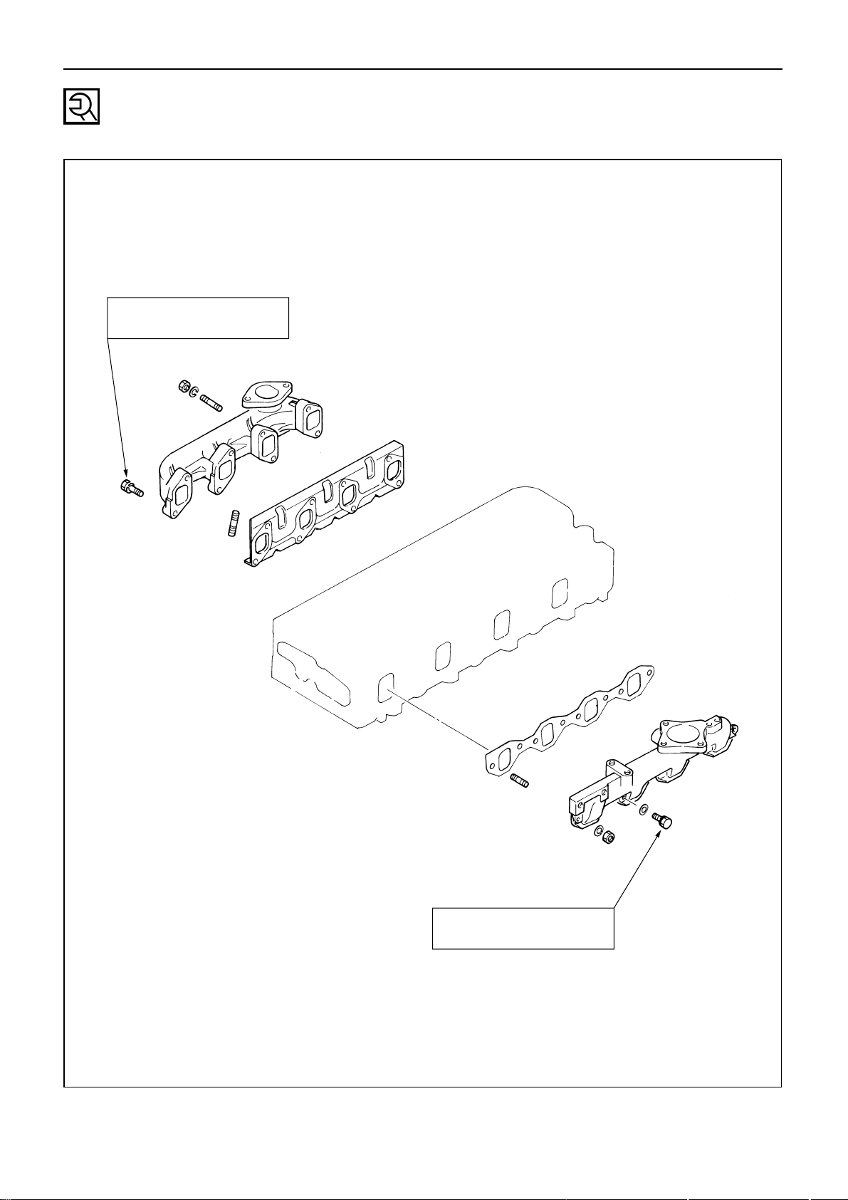
21. Exhaust Manifold
Loosen the exhaust manifold bolts a little at a time
in the numerical order shown in the illustration.
4851
2673
32
Page 36

ENGINE ASSEMBLY ( 1 )
15
14
16
17
11
12
13
3
9
10
5
4
8
7
6
2
1
★
★Repair kit
★
★
★
★
★
33
Disassembly Steps - 2
1. Water by-pass hose
2. Thermostat housing
3. Water pump
▲ 4. Injection nozzle holder
5. Glow plug and glow plug connector
6. Cylinder head cover
▲ 7. Rocker arm shaft and rocker arm
8. Push rod
▲ 9. Cylinder head
10. Cylinder head gasket
▲ 11. Crankshaft damper pulley with
dust seal
12. Timing gear case cover
13. Timing gear cover
14. Timing gear oil pipe
15. Idler gear “B” and shaft
▲ 16. Idler gear “A”
17. Idler gear shaft
Inverted Engine
Page 37

ENGINE ASSEMBLY ( 1 )
34
14
6
7
16
15
4
9
8
12
10
13
11
3
3a
★
2
5
1a
1
★
★Repair kit
Disassembly Steps - 3
1. Oil pan
1a. Oil pan (If so crankcase equipped)
2. Crankcase (If so equipped)
▲ 3. Flywheel
3a. Rear flywheel (If so equipped)
4. Flywheel housing
5. Oil pump with oil pipe
▲ 6. Camshaft with camshaft timing
gear and thrust plate
7. Timing gear case
▲ 8. Connecting rod cap with
lower bearing
▲ 9. Piston and connecting rod with
upper bearing
▲ 10. Crankshaft bearing cap with
lower bearing
11. Crankshaft thrust bearing
12. Crankshaft with crankshaft timing gear
▲ 13. Crankshaft upper bearing
▲ 14. Tappet
15. Crankshaft rear oil seal
16. Cylinder body
Page 38

ENGINE ASSEMBLY ( 1 )
Important Operations (Disassembly Steps - 2)
4. Injection Nozzle Holder
1) Remove the nozzle holder bracket nuts.
2) Use the nozzle holder remover and the sliding
hammer to remove the nozzle holder together
with the holder bracket.
Nozzle Holder Remover: 5-8840-2034-0
Sliding Humme: 5-8840-0019-0
7. Rocker Arm Shaft and Rocker Arm
Loosen the rocker arm shaft bracket bolts in numerical order a little at a time.
Note:
Failure to loosen the rocker arm shaft bracket bolts in
numerical order a little at a time will adversely effect the
rocker arm shaft.
1342
9. Cylinder Head
Loosen the cylinder head bolts in numerical order a
little at a time.
Note:
Failure to loosen the cylinder head bolts in numerical
order a little at a time will adversely effect the cylinder
head lower surface.
1
2
3
4
5
6
7
8
9
10
11
1213
14
15
16
17
35
Page 39

ENGINE ASSEMBLY ( 1 )
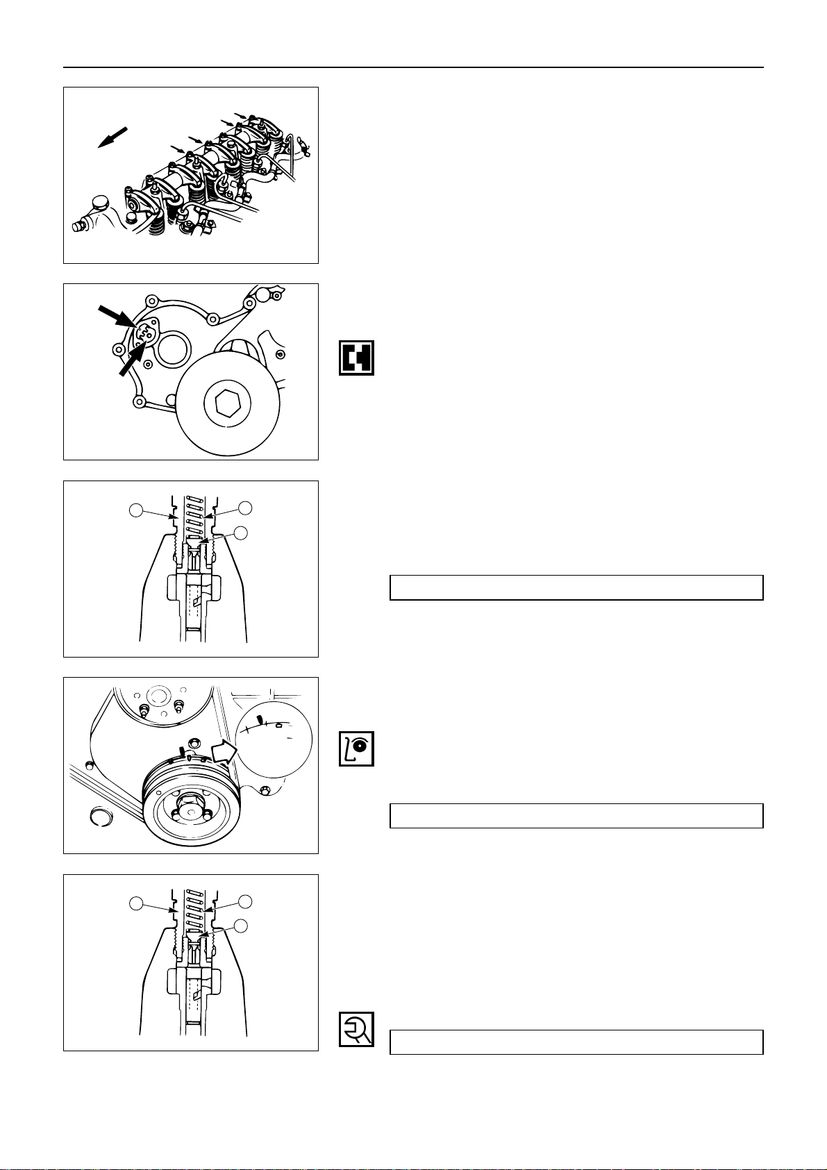
11. Crankshaft Damper Pulley with Dust Seal
1) Block the flywheel with a piece of wood to prevent it from turning.
2) Use the damper pulley remover to remove the
damper pulley.
Damper Pulley Remover
16. Idler Gear “A”
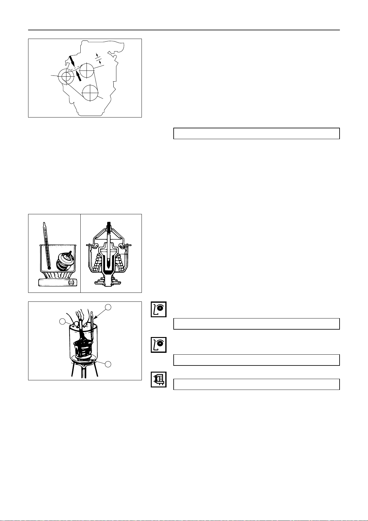
Measure the camshaft timing gear backlash, the
crankshaft timing gear backlash, and the idler gear
“A” end play before removing the idler gear “A”
and shaft.
Timing Gear Backlash Measurement
1) Set a dial indicator to the timing gear to be measured.
Hold both the gear to be checked and the adjoining
gear stationary.
2) Move the gear to be checked as far as possible to
both the right and the left.
Take the dial indicator reading.
If the measured value exceeds the specified limit,
the timing gear must be replaced.
Timing Gear Backlash mm(in.)
Standard Limit
0.10–0.17 (0.0039–0.0067) 0.30 (0.012)
Idler Gear “A” End Play Measurement
Insert a feeler gauge between the idler gear and the
thrust collar to measure the gap and determine the idler
gear end play.
If the measured value exceeds the specified limit, the
thrust collar must be replaced.
Idler Gear End Play mm(in.)
Standard Limit
0.07 (0.0028) 0.30 (0.012)
36
Page 40

ENGINE ASSEMBLY ( 1 )
Important Operations (Disassembly Steps - 3)
3. Flywheel
1) Block the flywheel with a piece of wood to prevent it from turning.
2) Loosen the flywheel bolts a little at a time in the
numerical order shown in the illustration.
1
2
3
4
5
6
6. Camshaft with Camshaft Timing Gear and Thrust
Plate
1) Remove the thrust plate bolts.
2) Pull the camshaft free along with the camshaft
timing gear and the thrust plate.
Note:
Be careful not to damage the camshaft journal, the cam,
and the camshaft during the disassembly procedure.
8. Connecting Rod Cap with Lower Bearing
If the connecting rod lower bearings are to be reinstalled, mark their fitting positions by tagging each
bearing with the cylinder number from which it was
removed.
9. Piston and Connecting Rod with Upper Bearing
1) Remove carbon deposits from the upper portion
of the cylinder wall with a scraper before removing the piston and connecting rod.
2) Move the piston to the top of the cylinder and
tap it with a hammer grip or similar object from
the connecting rod lower side to drive it out.
37
If the connecting rod upper bearings are to be reinstalled, mark their fitting positions by tagging each
bearing with the cylinder number from which it was
removed.
Page 41

ENGINE ASSEMBLY ( 1 )
10. Crankshaft Bearing Cap with Lower Bearing
1) Measure the crankshaft end play at the center
journal of the crankshaft.
Do this before removing the crankshaft bearing
caps.
If the measured value exceeds the specified
limit, the crankshaft thrust bearing must be
replaced.
Crankshaft End Play mm(in.)
Standard Limit
0.10 (0.0039) 0.30 (0.0118)
2) Loosen the crankshaft bearing cap bolts in
numerical order a little at a time.
If the crankshaft bearings are to be reinstalled,
mark their fitting positions by tagging each
bearing with the cylinder number from which it
was removed.
13. Crankshaft Upper Bearing
If the crankshaft upper bearings are to be reinstalled,
mark their fitting positions by tagging each bearing
with the cylinder number from which it was
removed.
14. Tappet
If the tappets are to be reinstalled, mark their fitting
positions by tagging each tappet with the cylinder
number from which it was removed.
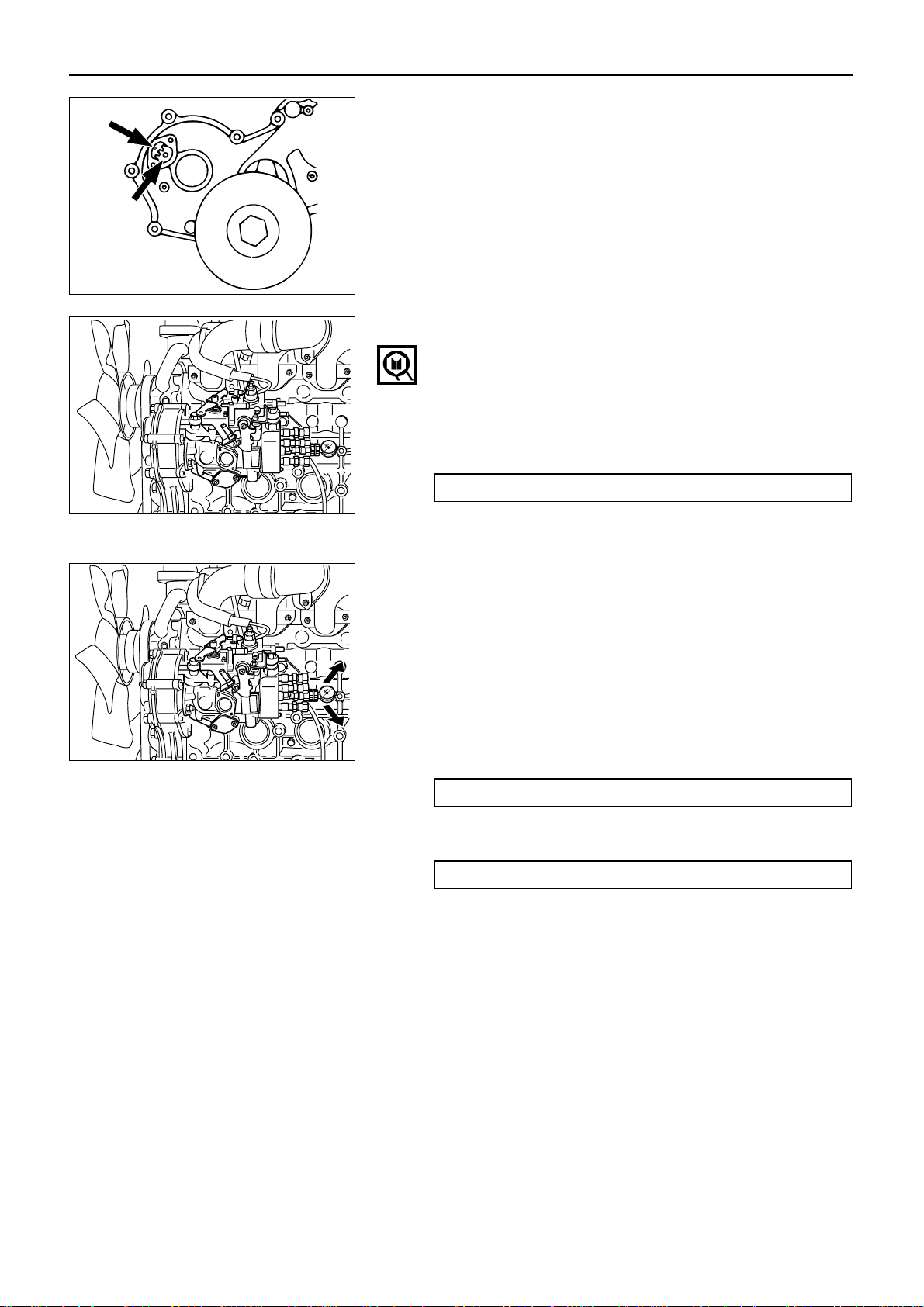
15. Crankshaft Rear Oil Seal (Axial Type)
Remove the flywheel housing.
With the oil seal pushed in deep, install the special
tool as shown in the illustration and remove the oil
seal.
Oil Seal Remover: 5-8840-2360-0
38
3
4
10
7
9
8
2
6
5
1
Page 42

ENGINE ASSEMBLY ( 1 )
39
DISASSEMBLY
SINGLE UNIT
ROCKER ARM SHAFT AND ROCKER ARM
Disassembly Steps
▲ 1. Rocker arm shaft snap ring
▲ 2. Rocker arm
▲ 3. Rocker arm shaft bracket
4. Rocker arm
5. Rocker arm shaft spring
6. Rocker arm shaft snap ring
7. Rocker arm shaft
2
6
1
7
5
4
3
Page 43

ENGINE ASSEMBLY ( 1 )
Important Operations
1. Rocker Arm Shaft Snap Ring
2. Rocker Arm
3. Rocker Arm Shaft Bracket
1) Use a pair of snap ring pliers to remove the
snap rings.
2) Remove the rocker arms.
3) Remove the rocker arm shaft bracket.
If the rocker arms and rocker arm shaft brackets
are to be reinstalled, mark their installation
positions by tagging each rocker arm and rocker
arm shaft bracket with the cylinder number from
which it was removed.
40
Page 44

ENGINE ASSEMBLY ( 1 )
CYLINDER HEAD
41
1
2
3
5
6
7
4
Disassembly Steps
▲ 1. Split collar
2. Valve spring upper seat
3. Valve spring
▲ 4. Intake and exhaust valves
5. Valve stem oil seal
6. Valve spring lower washer
7. Cylinder head
Page 45

ENGINE ASSEMBLY ( 1 )
42
Important Operations
1. Split Collar
1) Place the cylinder head on a flat wooden
surface.
2) Use the spring compressor to remove the split
collar.
Do not allow the valve to fall from the cylinder
head.
Spring Compressor: 9-8523-1423-0
4. Intake and Exhaust Valve
If the intake and exhaust valves are to be reinstalled,
mark their installation positions by tagging each
valve with the cylinder number from which it was
removed.
If there is excessive valve wear or damage, the valve
must be replaced.
Refer to Page 50 of “Inspection and Repair” for the
valve and valve seat insert procedure.
Note:
If there is excessive valve guide wear or damage, the
valve guide must be replaced.
Refer to Page 49 of “Inspection and Repair” for the valve
guide replacement procedure.
The valve and the valve guides must be replaced as a
set. Never replace only one or the other.
Page 46

ENGINE ASSEMBLY ( 1 )
43
PISTON AND CONNECTING ROD
6
2
7
4
3
5
1
Disassembly Steps
▲ 1. Connecting rod bearing
▲ 2. Piston ring
▲ 3. Piston pin snap ring
▲ 4. Piston pin
5. Connecting rod
▲ 6. Piston pin snap ring
▲ 7. Piston
Page 47

ENGINE ASSEMBLY ( 1 )
Important Operations
1. Connecting Rod Bearing
If the connecting rod bearings are to be reinstalled,
mark their fitting positions by tagging each bearing
with the cylinder number from which it was
removed.
2. Piston Ring
1) Clamp the connecting rod in a vise.
Take care not to damage the connecting rod.
2) Use a piston pin replacer to remove the piston
rings.
Piston Ring Replacer
Do not attempt to use some other tool to
remove the piston rings. Piston ring stretching
will result in reduced piston ring tension.
3. Piston Pin Snap Ring
4. Piston Pin Snap Ring
Use a pair of snap ring pliers to remove the piston
pin snap rings.
5. Piston Pin
7. Piston
Tap the piston pin out with a hammer and a brass
bar.
If the pistons are to be reinstalled, mark their installation positions by tagging each piston with the
cylinder number from which it was removed.
44
Page 48

ENGINE ASSEMBLY ( 1 )
45
CAMSHAFT, CAMSHAFT TIMING GEAR, AND THRUST PLATE
1
2
3
4
Disassembly Steps
▲ 1. Camshaft timing gear
▲ 2. Thrust plate
3. Feather key
4. Camshaft
Page 49

ENGINE ASSEMBLY ( 1 )
Important Operations
1. Camshaft Timing Gear
2. Thrust Plate
1) Clamp the camshaft in a vise.
Take care not to damage the camshaft.
2) Use the universal puller 1 to pull out the
camshaft timing gear 2 .
Universal Puller: 5-8840-0086-0
3) Remove the thrust plate 3 .
46
3
2
1
Page 50

ENGINE ASSEMBLY ( 2 )
47
SECTION 4
ENGINE ASSEMBLY ( 2 )
TABLE OF CONTENTS
ITEM PAGE
Inspection and repair ............................................................ 48
Page 51

INSPECTION AND REPAIR
Make the necessary adjustments, repairs, and part replacements if excessive wear or damage is
discovered during inspection.
ENGINE ASSEMBLY ( 2 )
CYLINDER HEAD
Cylinder Head Lower Face Warpage
1. Use a straight edge and a feeler gauge to measure
the four sides and the two diagonals of the cylinder
head lower face.
2. Regrind the cylinder head lower face if the measured values are greater than the specified limit but
less than the maximum grinding allowance.
If the measured values exceed the maximum grinding allowance, the cylinder head must be replaced.
Cylinder Head Lower Face Warpage mm(in)
Standard Limit
Maximum Grinding
Allwance
0.05
0.2 (0.008) 0.3 (0.012)
(0.002) or less
Cylinder Head Height (Reference) mm(in)
Standard Limit
91.95 (3.620) – 92.05 (3.624) 91.65 (3.60)
Note:
If the cylinder head lower face is reground, valve
depression must be checked.
EF
A
B
C
D
H
48
Exhaust Manifold Fitting Face Warpage
Use a straight edge and a feeler gauge to measure the
manifold cylinder head fitting face warpage.
Regrind the manifold cylinder head fitting faces if the
measured values are greater than the specified limit but
less than the maximum grinding allowance.
If the measured values exceed the maximum grinding
allowance, the cylinder head must be replaced.
Page 52

ENGINE ASSEMBLY ( 2 )
49
VALVE GUIDE
Valve Stem and Valve Guide Clearance
Measuring Method - I
1. With the valve stem inserted in the valve guide, set
the dial indicator needle to “0”.
2. Move the valve head from side to side.
Read the dial indicator.
Note the highest dial indication.
If the measured values exceed the specified limit,
the valve and the valve guide must be replaced as a
set.
Valve Stem Clearance mm(in)
Standard Limit
Intake Valve
0.039 – 0.069 0.20
(0.0015 – 0.0027) (0.008)
Exhaust Valve
0.064 – 0.096 0.25
(0.0025 – 0.0038) (0.0098)
Manifold Fitting Face Warpage mm (in)
Standard Limit
Maximum Grinding
Allwance
0.05
0.2 (0.008) 0.4 (0.016)
(0.002) or less
Measuring Method - II
1. Measure the valve stem outside diameter.
Refer to the Item “Valve Stem Outside Diameter”.
2. Use a caliper calibrator or a telescoping gauge to
measure the valve guide inside diameter.
Valve Guide Replacement
Valve Guide Removal
Use a hammer and the valve guide replacer to drive out
the valve guide from the cylinder head lower face.
Valve Guide Replacer: 9-8523-1212-0
Page 53

ENGINE ASSEMBLY ( 2 )
50
Valve Guide Installation
1. Apply engine oil to the valve guide outer circumference.
2. Attach the valve guide replacer to the valve guide.
3. Use a hammer to drive the valve guide into position
from the cylinder head upper face.
Valve Guide Replacer: 9-8523-1212-0
4. Measure the height of the valve guide upper end
from the upper face of the cylinder head.
Valve Guide Upper End Height (H)
(Reference) mm(in)
13.0 (0.512)
Note:
If the valve guide has been removed, both the valve and
the valve guide must be replaced as a set.
H
VALVE AND VALVE SEAT INSERT
Valve Stem Outside Diameter
Measure the valve stem diameter at three points.
If the measured value is less than the specified limit, the
valve and the valve guide must be replaced as a set.
Valve Stem Outside Diameter mm(in)
Standard Limit
Intake Valve
7.949 – 7.961 7.88
(0.3129 – 0.3134) (0.3102)
Exhaust Valve
7.921 – 7.936 7.88
(0.3118 – 0.3124) (0.3102)
Valve Thickness
Measure the valve thickness.
If the measured value is less than the specified limit, the
valve and the valve guide must be replaced as a set.
Intake and Exhaust Valve Thickness mm(in)
Standard Limit
1.8 (0.071) 1.5 (0.059)
Page 54

Valve Contact Width
1. Check the valve contact faces for roughness and
unevenness.
Make smooth the valve contact surfaces.
2. Measure the valve contact width.
If the measured value exceeds the specified limit,
the valve seat insert must be replaced.
Valve Contact Width mm(in)
Standard Limit
Intake 1.7 (0.067) 2.2 (0.087)
Exhaust 2.0 (0.079) 2.5 (0.098)
Valve Depression
1. Install the valve 1 to the cylinder head 2 .
2. Use a depth gauge or a straight edge with steel rule
to measure the valve depression from the cylinder
head lower surface.
If the measured value exceeds the specified limit,
the valve seat insert must be replaced.
Valve Depression mm(in)
Standard Limit
Intake 0.73 (0.029) 1.28 (0.050)
Exhaust 0.70 (0.028) 1.20 (0.047)
ENGINE ASSEMBLY ( 2 )
1
2
51
Valve Seat Insert Replacement
Valve Seat Insert Removal
1. Arc weld the entire inside circumference 1 of the
valve seat insert 2.
2. Allow the valve seat insert to cool for a few minutes.
This will invite contraction and make removal of the
valve seat insert easier.
1
2
3
4
Page 55

ENGINE ASSEMBLY ( 2 )
3. Use a screwdriver 3 to pry the valve seat insert
free.
Take care not to damage the cylinder head 4 .
4. Carefully remove carbon and other foreign material
from the cylinder head insert bore.
52
Valve Seat Insert Installation
1. Carefully place the attachment 1 (having a smaller
outside diameter than the valve seat insert) on the
valve seat insert 2 .
Note:
The smooth side of the attachment must contact the
valve seat insert.
2. Use a bench press 3 to gradually apply pressure to
the attachment and press the valve seat insert into
place.
Note:
Do not apply an excessive amount of pressure with the
bench press. Damage to the valve seat insert will result.
1
2
3
Valve Seat Insert Correction
1. Remove the carbon from the valve seat insert surface.
2. Use a valve cutter (15°, 45°, and 75° blades) to
minimize scratches and other rough areas. This will
bring the contact width back to the standard value.
Remove only the scratches and rough areas. Do not
cut away too much. Take care not to cut away
unblemished areas of the valve seat surface.
Valve Seat Angle 45°
Note:
Use an adjustable valve cutter pilot.
Do not allow the valve cutter pilot to wobble inside the
valve guide.
30˚
90˚
150˚
Page 56

Valve Spring Tension
Use a spring tester to measure the valve spring tension.
If the measured value is less than the specified limit, the
valve spring must be replace.
Valve Spring Tension kgf(lb/N)
Compressed Height Standard Limit
38.9 mm (1.53 in)
32.6 29.0
(71.9/319.6) (63.9/284.4)
ENGINE ASSEMBLY ( 2 )
3. Apply abrasive compound to the valve seat insert
surface.
4. Insert the valve into the valve guide.
5. Turn the valve while tapping it to fit the valve seat
insert.
6. Check that the valve contact width is correct.
7. Check that the valve seat insert surface is in contact
with the entire circumference of the valve.
53
VALVE SPRING
Valve Spring Free Height
Use a vernier caliper to measure the valve spring free
height.
If the measured value is less than the specified limit, the
valve spring must be replaced.
Valve Spring Free Height mm(in)
Standard Limit
49.7 (1.96) 48.2 (1.90)
Valve Spring Inclination
Use a surface plate and a square to measure the valve
spring inclination.
If the measured value exceeds the specified limit, the
valve spring must be replaced.
Valve Spring Inclination mm(in)
Standard Limit
1.5 (0.06) or less 2.5 (0.098)
Square
Page 57

Rocker Arm Shaft Outside Diameter
Use a micrometer to measure the rocker arm fitting
portion outside diameter.
If the measured value is less than the specified limit, the
rocker arm shaft must be replaced.
Rocker Arm Shaft Outside Diameter mm(in)
Standard Limit
18.98 – 19.00 (0.747 – 0.748) 18.85 (0.742)
ENGINE ASSEMBLY ( 2 )
ROCKER ARM SHAFT AND ROCKER ARM
Rocker Arm Shaft Run-Out
1. Place the rocker arm shaft on a V-block.
2. Use a dial indicator to measure the rocker arm shaft
central portion run-out.
If the run-out is very slight, correct the rocker arm
shaft run-out with a bench press. The rocker arm
must be at cold condition.
If the measured rocker arm shaft run-out exceeds
the specified limit, the rocker arm shaft must be
replaced.
Rocker Arm Shaft Run-Out mm(in)
Standard Limit
0.2 (0.008) 0.6 (0.024)
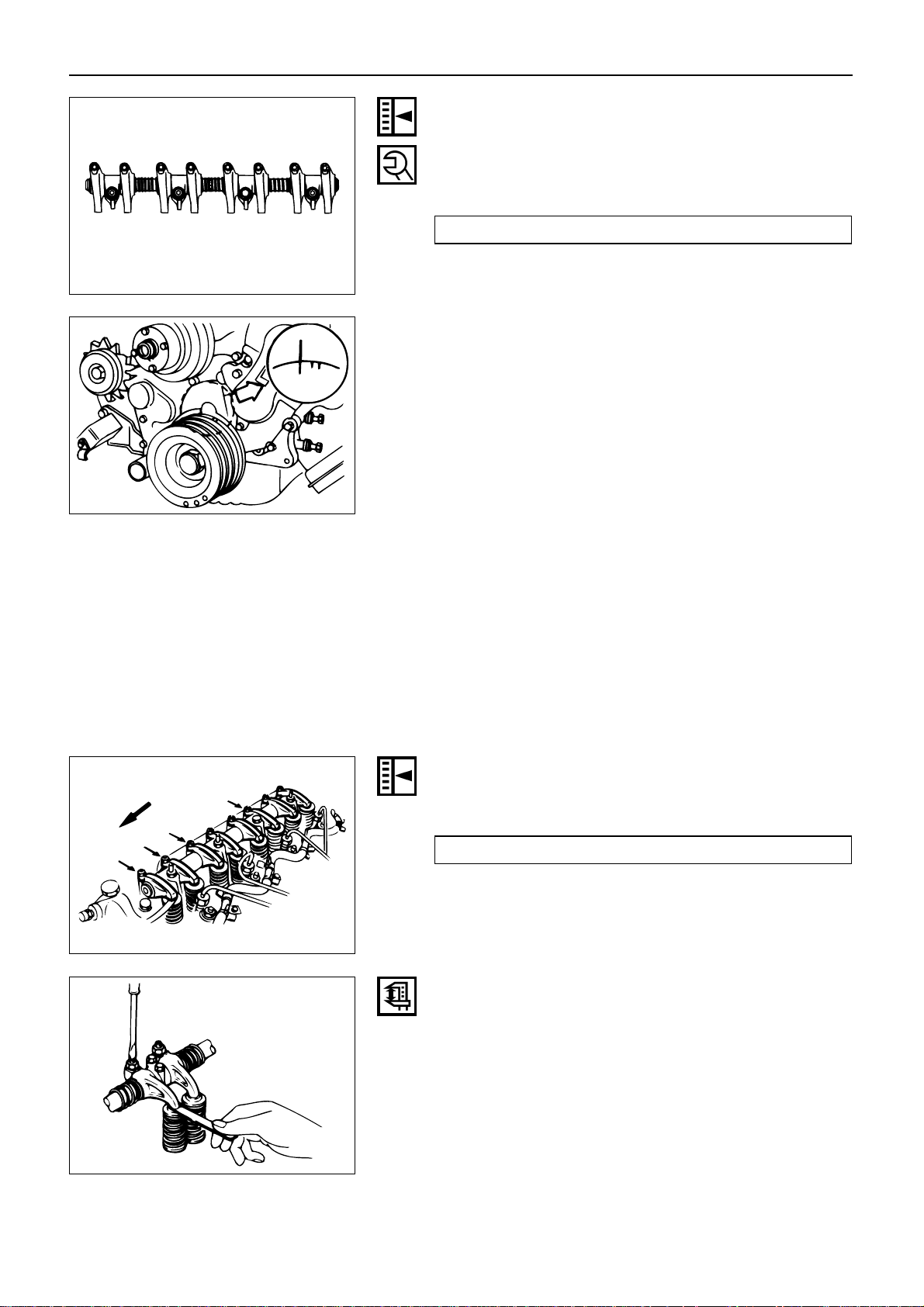
54
Rocker Arm Shaft and Rocker Arm Clearance
1. Use either a vernier caliper or a dial indicator to
measure the rocker arm bushing inside diameter.
Rocker Arm Bushing Inside Diameter mm(in)
Standard Limit
19.01 – 19.03 (0.748 – 0.749) 19.05 (0.750)
2. Measure the rocker arm shaft outside diameter.
If the measured value exceeds the specified limit,
replace either the rocker arm or the rocker arm shaft.
Rocker Arm and Rocker Arm Shaft Clearance mm(in)
Standard Limit
0.01 – 0.05 (0.0004 – 0.002) 0.2 (0.008)
Page 58

ENGINE ASSEMBLY ( 2 )
3. Check that the rocker arm oil port is free of obstructions.
If necessary, use compressed air to clean the rocker
arm oil port.
55
Rocker Arm Correction
Inspect the rocker arm valve stem contact surfaces for
step wear 1 and scoring 2 .
If the contact surfaces have light step wear or scoring,
they may be honed with an oil stone.
If the step wear or scoring is severe, the rocker arm must
be replaced.
CYLINDER BODY
Cylinder Body Upper Face Warpage
1. Remove the cylinder body dowel.
2. Remove the cylinder liner.
Refer to “Cylinder Liner Replacement”.
1
2
3. Use a straight edge 1 and a feeler gauge 2 to
measure the four sides and the two diagonals of the
cylinder body upper face.
1
2
Cylinder Body Upper Face Warpage mm(in)
Standard Limit
0.05 (0.002) or less 0.2 (0.008)
If the measured value is more than the limit, the
cylinder body must be replaced.
EF
A
B
C
D
Page 59

ENGINE ASSEMBLY ( 2 )
Cylinder Body Height (Reference) mm(in)
Standard
247.945 – 248.105 (9.7616 – 9.7679)
4. Reinstall the cylinder liner.
Refer to “Cylinder Body Bore Measurement”.
5. Reinstall the cylinder body dowel.
56
Cylinder Liner Bore Measurement
Use a cylinder indicator to measure the cylinder bore at
measuring point 1 in the thrust X – X and axial Y – Y
directions of the crankshaft.
Measuring Point 1 : Maximum wear portion
[11 – 15 mm (0.43 – 0.59 in)]
If the measured value exceeds the specified limit, the
cylinder liner must be replaced.
Cylinder Liner Bore mm(in)
Standard Limit
93.021 – 93.060 (3.662 – 3.663) 93.10 (3.665)
Note:
The inside of the dry type cylinder liner is chrome
plated. It cannot be rebored or honed.
If the inside of the cylinder liner is scored or scorched,
the cylinder liner must be replaced.
1
X
X
YY
Cylinder Liner Projection Inspection
1. Hold a straight edge 1 along the top edge of the
cylinder liner to be measured.
2. Use a feeler gauge 2 to measure each cylinder liner
projection.
Cylinder Liner Projection mm(in)
Standard
0 – 0.10 (0 – 0.0039)
The difference in the cylinder liner projection height
between any two adjacent cylinders must not
exceed 0.03 mm (0.0012 in).
1
2
Page 60

ENGINE ASSEMBLY ( 2 )
Cylinder Liner Replacement
Cylinder Liner Removal
1. Insert the cylinder liner remover 1 into the cylinder
body (from the lower side of the cylinder body) unit
it makes firm contact with the cylinder liner.
Cylinder Liner Remover: 5-8840-2039-0
(A-4JA1, A-4JB1)
2. Use a bench press 2 to slowly force the cylinder
liner from the cylinder body.
3. Discard the cylinder liner.
Note:
Take care not to damage the cylinder body upper face
during the cylinder liner removal procedure.
4. Measure the cylinder body upper face warpage.
Refer to “Cylinder Body Upper Face Warapage”.
1
2
57
Cylinder Liner Grade Selection
Measure the cylinder body inside diameter and select
the proper cylinder liner grade number corresponding to
the cylinder body inside diameter.
Standard Fitting Interference (Reference) mm(in)
0.001 – 0.019 (0.00004 – 0.00075)
If the cylinder liner fitting interference is too small,
engine cooling efficiency will be adversely affected.
If the cylinder liner fitting interference is too large, it will
be difficult to insert the cylinder liner into the cylinder
body.
Cylinder Body Bore Measurement
1. Take measurements at measuring point 1 across
positions (“W – W”), (“X – X”), (Y – Y) and (Z – Z).
Measuring Point 1 : 98 mm (3.86 in)
2. Calculate the average value of the four
measurements to determine the correct cylinder
grade.
Cylinder Liner Grade
Nominal Cylinder Body
Liner Grade
Dimension Bore Diameter
95.001 – 95.010
1
(3.74019 – 3.74055)
95.011 – 95.020
2
(3.74059 – 3.74094)
95.021 – 95.030
3
(3.74098 – 3.74133)
95.031 – 95.040
4
(3.74138 – 3.74173)
φ95
X
W
YY
Z
Z
W
X
Page 61

ENGINE ASSEMBLY ( 2 )
Cylinder Liner Installation
1. Cylinder Liner Installation Using The Special Tool.
1) Use new kerosene or diesel oil to thoroughly
clean the cylinder liners and bores.
2) Use compressed air to blow-dry the cylinder
liner and bore surfaces.
Note:
All foreign material must be carefully removed from the
cylinder liner and the cylinder bore before installation.
58
3) Insert the cylinder liner 1 into the cylinder body
2 from the top of the cylinder body.
1
2
3
4) Set the cylinder liner installer 3 to the top of the
cylinder liner.
Cylinder Liner Installer: 5-8840-2040-0
5) Position the cylinder body so that the installer
center 3 is directly beneath the bench press
shaft center 4.
Note:
Check that the cylinder liner is set perpendicular to the
bench press and that there is no wobble.
6) Use the bench press to apply a seating force of
500 kgf (1,102.5 lb/4,900 N) to the cylinder liner.
7) Apply a force of 2,500 kgf (5,512.5 lb/24,500 N)
to fully seat the cylinder liner.
8) After installing the cylinder liner, measure the
cylinder liner projection.
Refer to “Cylinder Liner Projection Inspection”.
2. Cylinder Liner Installation Using Dry Ice
If the cylinder liner is a chrome plated dry type, it is
advisable to use dry ice during the installation
procedure.
Cooling the cylinder liner with dry ice will cause the
cylinder liner to contact, thus making installation
easier.
Note:
It is important that the cylinder liner be inserted to the
cylinder body immediately after it has been cooled.
3
4
Page 62

ENGINE ASSEMBLY ( 2 )
WARNING:
DRY ICE MUST BE USED WITH GREAT CARE. CARELESS HANDLING OF DRY ICE CAN RESULT IN SEVERE
FROSTBITE.
Piston Selection
Select the same grade number as the one for the
cylinder liner inside diameter.
Grade of cylinder
Grade of piston Combination
inside diameter
AX AX OK
CX CX OK
AX CX NG
CX AX NG
59
Page 63

ENGINE ASSEMBLY ( 2 )
Piston Grade Selection
Measure the cylinder liner bore. Then select the
appropriate piston grade for the installed cylinder liner.
1. Measure the cylinder liner bore.
There are two measuring points ( 1 and 2 ).
Measure the cylinder liner bore in four different
direction (W – W, X – X, and Z – Z) at both measuring points.
Calculate the average value of the eight measurements to determine the correct cylinder liner bore.
Measuring Points 1 :
20 mm (0.79 in) for all A-4J models
2 :
140 mm (5.51 in) for A-4JA1
160 mm (6.30 in) for A-4JB1
Cylinder Liner Bore mm(in)
Standard Limit
93.021 – 93.060 (3.662 – 3.663) 93.10 (3.665)
Note:
It is most important that the correct piston grade be
used. Failure to select the correct piston grade will result
in engine failure.
X
X
YY
W
W
Z
Z
1
2
60
2. Measure the piston outside diameter.
Piston Measuring Point 1 : 70 mm (2.76 in)
Piston Grade mm(in)
Grade
Piston Outside Diameter
4JA1 4JB1
AX
92.979 – 92.994 92.989 – 93.004
(3.6606 – 3.6611) (3.6610 – 3.6615)
CX
92.995 – 93.010 93.005 – 93.020
(3.6612 – 3.6618) (3.6616 – 3.6622)
Cylinder Liner and Piston Clearance mm(in)
0.017 – 0.055 (0.0007 – 0.0022)
Note:
:Cylinder liner kit clearances are preset. However, the
cylinder liner installation procedure may result in slight
decreases in cylinder liner clearances. Always measure
the cylinder liner clearance after installation to be sure
that it is correct.
1
Page 64

ENGINE ASSEMBLY ( 2 )
61
TAPPET AND PUSH ROD
Visually inspect the tappet camshaft contact surfaces for
pitting, cracking, and other abnormal conditions. The
tappet must be replaced if any of these conditions are
present.
Refer to the illustration at the left.
1 Pitting
2 Cracking
3 Normal contact
4 Irregular contact
5 Irregular contact
Note:
The tappet surfaces are spherical. Do not attempt to
grind them with an oil stone or similar tool in an effort to
repair the tappet. If the tappet is damaged, it must be
replaced.
123
45
Tappet Outside Diameter
Measure the tappet outside diameter with a micrometer.
If the measured value is less than the specified limit, the
tappet must be replaced.
Tappet Outside Diameter mm(in)
Standard Limit
12.97 – 12.99 (0.5106 – 0.5114) 12.95 (0.5098)
Page 65

ENGINE ASSEMBLY ( 2 )
Tappet and Cylinder Body Clearance mm(in)
Standard Limit
0.03 (0.0012) 0.1 (0.0039)
62
Push Rod Curvature
1. Lay the push rod on a surface plate.
2. Roll the push rod along the surface plate and measure the push rod curvature with a thickness gauge.
If the measured value exceeds the specified limit,
the push rod must be replaced.
Push Rod Curvature mm(in)
Limit
0.3 (0.012)
3. Visually inspect both ends of the push rod for
excessive wear and damage. The push rod must be
replaced if these conditions are discovered during
inspection.
CAMSHAFT
Visually inspect the journals, the cams, the oil pump
drive gear, and the camshaft bearings for excessive
wear and damage. The camshaft and the camshaft
bearings must be replaced if these conditions are
discovered during inspection.
Camshaft Journal Diameter
Use a micrometer to measure each camshaft journal
diameter in two directions ((X – X) and (Y – Y)). If the
measured value is less than the specified limit, the
camshaft must be replaced.
Camshaft Journal Diameter mm(in)
Standard Limit
49.945 – 49.975 49.60
(1.9663 – 1.9675) (1.953)
X
X
YY
Page 66

ENGINE ASSEMBLY ( 2 )
Cam Height
Measure the cam height (H) with a micrometer. If the
measured value is less than the specified limit, the
camshaft must be replaced.
Cam Height H mm(in)
Standard Limit
42.08 (1.65) 41.65 (1.64)
H
63
Camshaft Run-Out
1. Mount the camshaft on V-blocks.
2. Measure the run-out with a dial indicator.
If the measured value exceeds the specified limit,
the camshaft must be replaced.
Camshaft Run-Out mm(in)
Standard Limit
0.02 (0.0008) 0.10 (0.004)
Camshaft and Camshaft Bearing
Use an inside dial indicator to measure the camshaft
bearing inside diameter.
Camshaft Bearing Inside Diameter mm(in)
Standard Limit
50.0 – 50.03 50.08
(1.9685 – 1.9697) (1.9716)
If the clearance between the camshaft bearing inside
diameter and the journal exceeds the specified limit, the
camshaft bearing must be replaced.
Camshaft Bearing Clearance mm(in)
Standard Limit
0.05 (0.002) 0.12 (0.005)
Camshaft Bearing Replacement
Camshaft Bearing Removal
1. Remove the cylinder body plug plate.
2. Use the camshaft bearing replacer to remove the
camshaft bearing.
Bearing Replacer: 5-8840-2038-0
Page 67

ENGINE ASSEMBLY ( 2 )
Camshaft Bearing Installation
1. Align the bearing oil holes with the cylinder body oil
holes.
2. Use the camshaft bearing replacer installer to install
the camshaft bearing.
Bearing Replacer: 5-8840-2038-0
64
Camshaft End Play
1. Before removing the camshaft gear 1, push the
thrust plate 2 as far as it will go toward the camshaft gear 3.
2. Use a feeler gauge to measure the clearance
between the thrust plate and the camshaft journal.
If the measured value exceeds the specified limit,
the thrust plate must be replaced.
Camshaft End Play mm(in)
Standard Limit
0.050 – 0.114 (0.002 – 0.0045) 0.2 (0.008)
1
2
3
Thrust Plate Replacement
Thrust Plate Removal
1. Use the universal puller 1 to remove the camshaft
timing gear 2 .
Universal Puller: 5-8840-0086-0
2. Remove the thrust plate 3 .
1
2
3
Thrust Plate Installation
1. Install the thrust plate.
2. Apply engine oil to the bolt setting face and the bolt
threads.
3. Install the camshaft gear.
Camshaft Gear Torque kgf·m(lb.ft/N·m)
10.0 – 12.0 (72.4 – 86.8/98.1 – 117.7)
Page 68

ENGINE ASSEMBLY ( 2 )
CRANKSHAFT AND BEARING
Inspect the surface of the crankshaft journals and
crankpins for excessive wear and damage.
Inspect the oil seal fitting surfaces for excessive wear
and damage.
Inspect the oil ports for obstructions.
Note:
To increase crankshaft strength, tufftriding (Nitrizing
Treatment) has been applied. Because of this, it is not
possible to regrind the crankshaft surfaces.
65
Crankshaft Tufftriding Inspection
1. Use an organic cleaner to thoroughly clean the
crankshaft. There must be no traces of oil on the
surfaces to be inspected.
2. Prepare a 5 – 10% solution of ammonium cuprous
chloride (dissolved in distilled water).
3. Use a syringe to apply the solution to the surface to
be inspected.
Hold the surface to be inspected perfectly horizontal
to prevent the solution from running.
Note:
Do not allow the solution to come in contact with the oil
ports and their surrounding area.
The portion to be tested
shall be held horizontally
so as not to let the test
solution flow.
The sliding surface
of the pin
or journal.
Test liquid should
not be applied to
the area around the
oil port.
Approximately
10mm
Judgment
1. Wait for thirty to forty seconds.
If there is no discoloration after thirty or forty sec-
onds, the crankshaft is usable.
If discoloration appears (the surface being tested
will become the color of copper), the crankshaft
must be replaced.
2. Steam clean the crankshaft surface immediately
after completing the test.
Page 69

Crankshaft Run-Out
1. Set a dial indicator to the center of the crankshaft
journal.
2. Gently turn the crankshaft in the normal direction of
rotation.
Read the dial indicator as you turn the crankshaft.
If the measured value exceeds the specified limit,
the crankshaft must be replaced.
Crankshaft Run-Out mm(in)
Standard Limit
0.05 (0.002) or less 0.08 (0.0031)
ENGINE ASSEMBLY ( 2 )
Note:
The ammonium cuprous chloride solution is highly corrosive. Because of this, it is imperative that the surfaces
being tested be cleaned immediately after completing
the test.
66
Bearing Tension
Check to see if the bearing has enough tension, so that a
good finger pressure is needed to fit the bearing into
position.
Crankshaft Journal and Crankpin Diameter
1. Use a micrometer to measure the crankshaft journal
diameter across points (“1 – 1”) and (“2 – 2”).
2. Use the micrometer to measure the crankshaft
journal diameter at the two points ( 3 and 4 ).
3. Repeat Steps 1 and 2 to measure the crankpin
diameter.
If the measured values are less than the limit, the
crankshaft must be replaced.
22
1
1
3
4
Page 70

ENGINE ASSEMBLY ( 2 )
Crankshaft Journal Diameter mm(in)
Standard Limit
A-4JA1
59.917 – 59.932 59.910
(2.3589 – 2.3595) (2.3587)
A-4JB1
69.917 – 69.932 69.910
(2.7526 – 2.7531) (2.7524)
Crankpin Diameter mm(in)
Standard Limit
52.915 – 52.930 (2.0833 – 2.0839) 52.906 (2.0829)
Crankshaft Journal and Crankpin
Uneven Wear mm(in)
Standard Limit
0.05 (0.002) or less 0.08 (0.0031)
67
Crankshaft Journal and Bearing Clearance
If the clearance between the measured bearing inside
diameter and the crankshaft journal diameter exceeds
the specified limit, the bearing and/or the crankshaft
must be replaced.
Crankshaft Bearing Cap Bolt
Torque kgf·m(lb.ft./N·m)
16.0 – 18.0 (115.7 – 130.2/156.9 – 176.5)
Crankshaft brg’ cap Bolt Torque
Crankshaft Journal and
Bearing Clearance mm(in)
Standard Limit
0.035 – 0.080 (0.0014 – 0.0031) 0.11 (0.0043)
Connecting Rod Bearing Inside Diameter
1. Install the bearing to the connecting rod big end.
2. Tighten the bearing cap to the specified torque.
Connecting Rod Bearing Cap Bolt
Torque kgf·m(lb.ft/N·m)
8.0 – 9.0 (57.9 – 65.1/78.4 – 88.2)
3. Use a inside dial indicator to measure the connecting rod bearing inside diameter.
Page 71

ENGINE ASSEMBLY ( 2 )
Crankpin and Bearing Clearance
If the clearance between the measured bearing inside
diameter and the crankpin exceeds the specified limit,
the bearing and/or the crankshaft must be replaced.
Crankpin and Bearing Clearance mm(in)
Standard Limit
0.029 – 0.066 (0.0011 – 0.0026) 0.10 (0.0039)
68
Clearance Measurements (With Plastigage)
Crankshaft Journal and Bearing Clearance
1. Clean the cylinder body, the journal bearing fitting
surface, the bearing caps, and the bearings.
2. Install the bearings to the cylinder body.
3. Carefully place the crankshaft on the bearings.
4. Rotate the crankshaft approximately 30° to seat the
bearing.
5. Place the Plastigage (arrow) over the crankshaft
journal across the full width of the bearing.
6. Install the bearing caps with the bearing.
7. Tighten the bearing caps to the specified torque.
Crankshaft Bearing Cap Bolt
Torque kgf·m(lb.ft/N·m)
16.0 – 18.0 (115.7 – 130.2/156.9 – 176.5)
Do not allow the crankshaft to turn during bearing
cap installation and tightening.
8. Remove the bearing cap.
Page 72

ENGINE ASSEMBLY ( 2 )
9. Compare the width of the Plastigage attached to
either the crankshaft or the bearing against the scale
printed on the Plastigage container.
If the measured value exceeds the limit, perform the
following additional steps.
1) Use a micrometer to measure the crankshaft
outside diameter.
2) Use an inside dial indicator to measure the
bearing inside diameter.
If the crankshaft journal and bearing clearance
exceeds the limit, the crankshaft and/or the
bearing must be replaced.
Crankshaft Journal and Bearing Clearance mm(in)
Standard Limit
0.035 – 0.080 0.11
(0.0014 – 0.0036) (0.0043)
69
Crankpin and Bearing Clearance
1. Clean the crankshaft, the connecting rod, the bear ing cap, and the bearings.
2. Install the bearing to the connecting rod and the
bearing cap.
Do not allow the crankshaft to move when installing
the bearing cap.
3. Prevent the connecting rod from moving.
4. Attach the Plastigage to the crankpin.
Apply engine oil to the Plastigage to keep it from
falling.
Page 73

ENGINE ASSEMBLY ( 2 )
5. Install the bearing cap and tighten it to the specified
torque.
Do not allow the connecting rod to move when
installing and tightening the bearing cap.
Connecting Rod Bearing Cap Bolt
Torque kgf·m(lb.ft/N·m)
8.0 – 9.0 (57.9 – 65.1/78.4 – 88.2)
6. Remove the bearing cap.
7. Compare the width of the Plastigage attached to
either the crankshaft or the bearing against the scale
printed on the Plastigage container.
If the measured value exceeds the specified limit,
perform the following additional steps.
1) Use a micrometer to measure the crankpin outside diameter.
2) Use an inside dial indicator to measure the
bearing inside diameter.
If the crankpin and bearing clearance exceeds
the specified limit, the crankshaft and/or the
bearing must be replaced.
Crankpin and Bearing Clearance mm(in)
Standard Limit
0.029 – 0.066 0.10
(0.0011 – 0.0026) (0.0039)
70
Crankshaft Timing Gear Replacement
Crankshaft Timing Gear Removal
1. Use the crankshaft gear remover 1 to remove the
crankshaft gear 2 .
2. Remove the crankshaft feather key.
Crankshaft Timing Gear Remover: 9-8840-2057-0
1
2
Crankshaft Timing Gear Installation
1. Install the crankshaft gear.
2. Use the crankshaft gear installer 1 to install the
crankshaft gear 2 .
The crankshaft gear timing mark (“X – X”) must be
facing outward.
Crankshaft Gear Installer: 9-8522-0020-0
1
2
Page 74

ENGINE ASSEMBLY ( 2 )
CRANKSHAFT PILOT BEARING
Check the crankshaft pilot bearing for excessive wear
and damage and replace it if necessary.
71
Crankshaft Pilot Bearing Replacement
Crankshaft Pilot Bearing Removal
Use the pilot bearing remover to remove the pilot bear-
ing.
Pilot Bearing Remover: 5-8840-2000-0
Sliding Hammer: 5-8840-0019-0
Crankshaft Pilot Bearing Installation
1. Place the crankshaft pilot bearing horizontally across
the crankshaft bearing installation hole.
2. Tap around the edges of the crankshaft pilot bearing
outer races with a brass hammer to drive the bearing into the crankshaft bearing installation hole.
Pilot Bearing Installer: 5-8522-0024-0
Note:
Strike only the crankshaft pilot bearing outer races with
the hammer. Do not strike the bearing inner races.
Bearing damage and reduced bearing service life will
result.
Page 75

ENGINE ASSEMBLY ( 2 )
FLYWHEEL AND RING GEAR
Flywheel
1. Inspect the flywheel friction surface for excessive
wear and heat cracks.
2. Measure the flywheel friction surface wear amount
(depth)
The flywheel friction surface area actually making
contact with the clutch driven plate (the shaded area
in the illustration) will be smaller than the original
machined surface area.
There will be a ridge on the flywheel surface area.
Be sure to measure the surface wear in the area
inside the ridge.
If the measured value is between the standard and
the specified limit, the flywheel may be reground.
If the measured value exceeds the specified limit,
the flywheel must be replaced.
Flywheel Friction Surface Depth 1 mm(in)
Limit
1.0 (0.04) or more
Note:
Because a ridge is produced at the flywheel friction surface as illustrated, do not measure the friction surface
wear amount at the non-ridge area but be sure to
measure it at the rear-friction surface which is shown in
the illustration by shaded area.
1
72
Ring Gear Replacement
Ring Gear Removal
Strike around the edges of the ring gear with a hammer
and diesel to remove it.
Ring Gear
Inspect the ring gear.
If the ring gear teeth are broken or excessively worn, the
ring gear must be replaced.
Page 76

ENGINE ASSEMBLY ( 2 )
Ring Gear Installation
1. Heat the ring gear evenly with a gas burner to invite
thermal expansion.
Do not allow the temperature of the gas burner to
exceed 200°C (390°F).
2. Install the ring gear when it is sufficiently heated.
The ring gear must be installed with the chamfer
facing the clutch.
Note:
Another method of heating the ring gear to invite thermal expansion is to soak a rag in diesel fuel, wrap the
diesel fuel soaked rag around the rim of the ring gear,
and then light the rag.
73
1
2
PISTON RING
Piston Ring Gap
1. Insert the piston ring horizontally into the cylinder
liner.
2. Use a piston inserted upside down to push the
piston ring into the cylinder liner until it reaches
either measuring point 1 or measuring point 2.
Cylinder liner diameter is the smallest at these two
points.
Do not allow the piston ring to slant to one side or
the other. It must be perfectly horizontal.
3. Use a feeler gauge to measure the piston ring gap.
Measuring Point 1 : 10 mm (0.39 in)
or
Measuring Point 2 : 120 mm (4.72 in)
If the piston ring gap exceeds the specified limit, the
piston ring must be replaced.
PISTON
Piston Grade Selection and Cylinder Liner Bore
Measurement
Refer to the Section “CYLINDER BODY”, Item “Cylinder
Liner Bore Measurement” for details on piston grade
selection and cylinder or liner bore measurement.
Page 77

ENGINE ASSEMBLY ( 2 )
Piston Ring Gap mm(in)
Standard Limit
1st Compression Ring
0.20 – 0.40
2nd Compression Ring
(0.008 – 0.016)
Oil Ring
0.10 – 0.30
(0.004 – 0.012)
Piston Ring and Piston Ring Groove Clearance
Use a feeler gauge to measure the clearance between
the piston ring and the piston ring groove at several
points around the piston.
If the clearance between the piston ring and the piston
ring groove exceeds the specified limit, the piston ring
must be replaced.
Piston Ring and Piston Ring Groove
Clearance mm(in)
Standard Limit
1st
Compression Ring
0.090 – 0.125
(0.0035 – 0.0049)
2nd Compression Ring
0.050 – 0.075 0.15
(0.002 – 0.003) (0.006)
Oil Ring
0.030 – 0.070
(0.0012 – 0.0028)
Visually inspect the piston. If a piston ring groove is
damaged or distorted, the piston must be replaced.
74
1.5
(0.059)
Page 78

PISTON PIN
Piston Pin Diameter
Use a micrometer to measure the piston pin outside
diameter at several points.
If the measured value is less than the specified limit, the
piston pin must be replaced.
Piston Pin Diameter mm(in)
Standard Limit
31.0 (1.220) 30.97 (1.219)
Piston Pin and Piston Clearance
Use an inside dial indicator to measure the piston pin
hole (in the piston).
Piston Pin Hole mm(in)
Standard
29.002 – 29.007
Piston Pin and Piston Pin Hole
Clearance mm(in)
0.002 – 0.015 (0.00008 – 0.0006)
Piston Pin and Connecting Rod Small End Bushing
Clearance
Use a caliper calibrator and a dial indicator to measure
the piston pin and connecting rod small end bushing
clearance.
If the clearance between the piston pin and the connecting rod small end bushing exceeds the specified limit,
replace the piston pin and/or the connecting rod
bushing.
Piston Pin and Connecting Rod Small
End Bushing Clearance mm(in)
Standard Limit
0.008 – 0.020 0.05
(0.0003 – 0.0008) (0.002)
ENGINE ASSEMBLY ( 2 )
Connecting Rod Bushing Replacement
Connecting Rod Bushing Removal
1. Clamp the connecting rod in a vise.
2. Use the connecting rod bushing remover to remove
the connecting rod bushing.
Connecting Rod Bushing Replacer
75
Page 79

CONNECTING ROD
Connecting Rod Alignment
Use a connecting rod aligner to measure the distortion
and the parallelism between the connecting rod big end
hole and the connecting rod small end hole.
If either the measured distortion or parallelism exceed
the specified limit, the connecting rod must be replaced.
Connecting Rod Alignment
Per Length of 100 mm (3.94 in) mm(in)
Standard Limit
Distortion
0.20
0.05 or Less
(0.008)
(0.002)
0.15
Parallelism
(0.006)
ENGINE ASSEMBLY ( 2 )
Connecting Rod Bushing Installation
1. Clamp the connecting rod in a vice.
2. Use the connecting rod bushing installer to install
the connecting rod bushing.
Connecting Rod Bushing Replacer:
3. Use a piston pin hole grinder 1 fitted with a reamer
2 to ream the piston pin hole.
1
2
76
Page 80

ENGINE ASSEMBLY ( 2 )
Connecting Rod Side Face Clearance
1. Install the connecting rod to the crankpin.
2. Use a feeler gauge to measure the clearance
between the connecting rod big end side face and
the crankpin side face.
If the measured value exceeds the specified limit,
the connecting rod must be replaced.
Connecting Rod and Crankpin Side Face
Clearance mm(in)
Standard Limit
0.23 (0.009) 0.35 (0.014)
IDLER GEAR SHAFT AND IDLER GEAR
Idler Gear Shaft Outside Diameter
Use a micrometer to measure the idler gear shaft outside diameter.
If the measured value is less than the specified limit, the
idler gear must be replaced.
Idler Gear Shaft Outside Diameter mm(in)
Standard Limit
44.95 – 44.98 44.90
(1.770 – 1.771) (1.767)
77
Page 81

ENGINE ASSEMBLY ( 2 )
Idler Gear “A” Inside Diameter
1. Use an inside dial indic ator to measure the idler
gear
Idler Gear Inside Diameter mm(in)
Standard Limit
45.0 – 45.03 45.10
(1.7717 – 1.7728) (1.7756)
If the clearance between the idler gear shaft outside
diameter and the idler gear inside diameter exceeds the
limit, the idler gear must be replaced.
Idler Gear Shaft and Idler Gear
Clearance mm(in)
Standard Limit
0.025 – 0.085 0.2
(0.0010 – 0.0033) (0.008)
Idler Gear “B”
Bearing replacement
Use a suitable bar and a bench press or hammer.
Bearing projection amount should be within the spec-
ified height.
mm(in)
Projection 1 0.4 – 0.6 (0.016 – 0.024)
Height 2 23.7 – 24.0 (0.933 – 0.945)
1
2
Crankshaft Front Oil Seal Replacement
Oil Seal Removal
Use a plastic hammer and a screwdriver to tap around
the oil seal to free it from the gear case.
Take care not to damage the oil seal fitting surfaces.
TIMING GEAR CASE COVER
Replace the crankshaft front oil seal if it is excessively
worn or damaged.
78
Page 82

ENGINE ASSEMBLY ( 2 )
Oil Seal Installation
1. Apply a coat of engine oil to the oil seal lip circumference.
2. Use the oil seal installer and the installer grip to
insert the oil seal 1 mm (0.039 in) into the front portion of the timing gear case.
Oil Seal Installer: 5-8840-2061-0
79
Page 83

80
MEMO
Page 84

ENGINE ASSEMBLY ( 3 )
81
SECTION 5
ENGINE ASSEMBLY ( 3 )
TABLE OF CONTENTS
ITEM PAGE
Reassembly..................................................................... 82
Page 85

REASSEMBLY
SINGLE UNIT
ROCKER ARM SHAFT AND ROCKER ARM
ENGINE ASSEMBLY ( 3 )
82
Reassembly Steps
▲ 1. Rocker arm shaft
2. Rocker arm shaft snap ring
3. Rocker arm
4. Rocker arm shaft bracket
5. Rocker arm
6. Rocker arm shaft spring
7. Rocker arm shaft snap ring
3
2
4
5
6
1
7
Page 86

ENGINE ASSEMBLY ( 3 )
Important Operations
83
1. Rocker Arm Shaft
1) Position the rocker arm shaft with the large oil
hole (Dia. 4 mm (0.157 in)) facing the front of the
engine.
2) Install the rocker arm shaft together with the
rocker arm, the rocker arm shaft bracket, and
the spring.
Page 87

ENGINE ASSEMBLY ( 3 )
CYLINDER HEAD
84
Reassembly Steps
1. Cylinder head
2. Valve spring lower washer
▲ 3. Valve stem oil seal
▲ 4. Intake and exhaust valve
▲ 5. Valve spring
6. Valve spring upper seat
▲ 7. Split collar
7
6
5
3
2
1
4
Page 88

ENGINE ASSEMBLY ( 3 )
3. Valve Stem Oil Seal
1) Apply a coat engine oil to the oil seal inner face.
2) Use an oil seal installer to install the oil seal to
the valve guide.
Oil Seal Installer: 5-8840-2033-0
4. Intake and Exhaust Valve
1) Apply a coat of engine oil to valve stem.
2) Install the intake and exhaust valves.
3) Turn the cylinder head up to install the valve
springs.
Take care not to allow the installed valves to fall
free.
5. Valve Spring
1) Turn the cylinder head up to install the valve
springs.
2) Install the valve springs with the fine pitched
end (painted pink) facing down.
Take care not to allow the installed valves to fall
free.
7. Split Collar
1) Use the spring compressor to push the valve
spring into position.
Spring Compressor: 9-8523-1423-0
2) Install the split collar to the valve stem.
3) Set the split collar by tapping around the bead
of the collar with a rubber hammer.
85
Important Operations
Page 89

ENGINE ASSEMBLY ( 3 )
86
PISTON AND CONNECTING ROD
Reassembly Steps
▲ 1. Piston
▲ 2. Piston pin snap ring
▲ 3. Connecting rod
▲ 4. Piston pin
5. Piston pin snap ring
▲ 6. Piston ring
▲ 7. Connecting rod bearing
2
6
1
4
5
3
7
Page 90

ENGINE ASSEMBLY ( 3 )
1. Piston
2. Piston pin snap ring
3. Connecting rod
1) Clamp the connecting rod in a vise.
Take care not to damage the connecting rod.
2) Use a pair of snap ring pliers to install the piston
pin snap ring to the piston.
87
3) Install the piston to the connecting rod.
The piston head front mark 1 and the con-
necting rod “ISUZU” casting mark 2 must be
facing the same direction.
1
2
Important Operations
4. Piston pin
1) Apply a coat of engine oil to the piston pin and
the piston pin hole.
2) Use your fingers to force the piston pin into the
piston until it makes contact with the snap ring.
3) Use your fingers to force the piston pin snap
ring into the piston snap ring groove.
4) Check that the connecting rod moves smoothly
on the piston pin.
Page 91

ENGINE ASSEMBLY ( 3 )
6. Piston Ring
1) Use a piston ring replacer to install the three
piston rings.
Piston Ring Replacer:
Install the piston rings in the order shown in the
illustration.
1 Oil ring (Coil expander type)
2 2nd compression ring (Taper undercut type)
3 1st compression ring (Barrel face type)
Note:
Install the compression rings with the stamped side
facing up.
Insert the expander coil into the oil ring groove so that
there is no gap on either side of the expander coil before
installing the oil ring.
2) Apply engine oil to the piston ring surfaces.
3) Check that the piston rings rotate smoothly in
the piston ring grooves.
1
2
3
88
7. Connecting Rod Bearing
Carefully wipe any oil or other foreign material from
the connecting rod bearing back face and the
connecting rod bearing fitting surface.
Page 92

ENGINE ASSEMBLY ( 3 )
89
CAMSHAFT, CAMSHAFT TIMING GEAR, AND THRUST PLATE
Reassembly Steps
1. Camshaft
2. Feather key
3. Thrust plate
▲ 4. Camshaft timing gear
4
3
2
1
Page 93

ENGINE ASSEMBLY ( 3 )
4. Camshaft Timing Gear
1) Install the thrust plate 1 .
2) Apply engine oil to the bolt threads 2 .
3) Install the camshaft timing gear with the timing
mark stamped side facing out.
Camshaft Timing Gear Bolt Torque kgf·m(lb.ft/N·m)
10.0 – 12.0 (72.4 – 86.8/98.1 – 117.7)
1
2
90
Important Operations
Page 94

ENGINE ASSEMBLY ( 3 )
91
MEMO
Page 95

ENGINE ASSEMBLY ( 3 )
REASSEMBLY
92
2
8
7
1
13
14
9
10
4
6
3
5
15
15a
★
11
12
16a
16
★
★Repair kit
Reassembly Steps – 1
▲ 1. Cylinder body
▲ 2. Tappet
▲ 3. Crankshaft upper bearing
▲ 4. Crankshaft with crankshaft timing gear
▲ 5. Crankshaft thrust bearing
▲ 6. Crankshaft bearing cap with lower
bearing
▲ 7. Timing gear case
▲ 8. Camshaft with camshaft timing gear
and thrust plate
▲ 9. Piston and connecting rod with upper
bearing
▲ 10. Connecting rod cap with lower bearing
▲ 11. Crankcase (If so equipped)
▲ 12. Oil pump with oil pipe
▲ 13. Crankshaft rear oil seal
▲ 14. Flywheel housing
▲ 15. Flywheel
15a Rear flywheel (If so equipped)
▲ 16. Oil pan
16a Oil pan (If so crankcase equipped)
Inverted Engine
Page 96

ENGINE ASSEMBLY ( 3 )
93
3
4
2
1
7
6
5
12
9
8
15
16
10
11
17
13
14
★
★Repair kit
★
★
★
★
★
Reassembly Steps – 2
▲ 1. Idler gear shaft
▲ 2. Idler gear “A”
▲ 3. Idler gear “B”
4. Timing gear oil pipe
▲ 5. Timing case cover
6. Timing gear case cover
▲ 7. Crankshaft damper pulley with dust
seal
▲ 8. Cylinder head gasket
▲ 9. Cylinder head
10. Push rod
▲ 11. Rocker arm shaft and rocker arm
▲ 12. Water pump
▲ 13. Thermostat housing
14. Water by-pass hose
▲ 15. Glow plug and glow plug connector
seal
▲ 16. Injection nozzle holder
17. Cylinder head cover
Page 97

ENGINE ASSEMBLY ( 3 )
1. Cylinder Body
Use compressed air to thoroughly clean the inside
and outside surfaces of the cylinder body, the oil
holes, and the water jackets.
94
Important Operations (Reassembly Steps-1)
2. Tappet
1) Apply a coat of engine oil to the tappet 1 and
the cylinder body tappet insert holes 2 .
2) Locate the position mark applied at disassembly
(if the tappet is to be reused).
Note:
The tappet must be installed before the camshaft.
1
2
3. Crankshaft Upper Bearing
The crankshaft upper bearings have an oil hole and
an oil groove. The lower bearings do not.
1) Carefully wipe any foreign material from the
crankshaft upper bearing and the crankshaft
upper bearing fitting surfaces.
2) Locate the position mark applied at disassembly
if the removed crankshaft upper bearings are to
be reused.
4. Crankshaft with Crankshaft Timing Gear
Apply an ample coat of engine oil to the crankshaft
journals and the crankshaft bearing surfaces before
installing the crankshaft.
Note:
Do not apply engine oil to the bearing back faces and the
cylinder body bearing fitting surfaces.
Page 98

ENGINE ASSEMBLY ( 3 )
5. Crankshaft Thrust Bearing
1) Apply an ample coat of engine oil to the crankshaft thrust bearings.
2) Install the crankshaft thrust bearings to the
crankshaft center journal.
The crankshaft thrust bearing oil groove must
be facing the sliding face.
6. Crankshaft Bearing Cap with Lower Bearing
1) Apply silicon adhesive to the cylinder body No.
5 bearing cap fitting surface at the points shown
in the illustration.
Note:
Be sure that the bearing cap fitting surface is completely
free of oil before applying the silicon adhesive.
Do not allow the silicon adhesive to obstruct the cylinder
thread holes and bearings.
2) Install the bearing caps.
The bearing cap arrow marks must be facing the
front of the engine.
The arrow mark journal number must corre-
spond to the journal to which the bearing cap is
installed.
Note:
The No. 4 journal bearing cap does not have a number
stamped on it.
1 2 3 Nile
5
3) Apply a coat of engine oil to the bearing cap
bolts.
4) Tighten the crankshaft bearing cap bolts to the
specified torque a little at a time in the sequence
shown in the illustration.
Crankshaft Bearing Cap Torque kgf·m(lb.ft/N·m)
16.0 – 18.0 (115.7 – 130.2/156.9 – 176.5)
5) Check to see that the crankshaft turns smoothly
by rotating it manually.
1
23
4
5
6
7
8
9
10
7. Timing Gear Case
1) Tighten the timing gear case with timing gear
case gasket to the specified torque.
Timing Gear Case Bolt Torque kgf·m(lb.ft/N·m)
1.4 – 2.4 (10.1 – 17.3/13.7 – 23.5)
2) Cut away any excessive flash from the timing
gear gasket.
95
Page 99

ENGINE ASSEMBLY ( 3 )
8. Camshaft with Camshaft Timing Gear and Thrust
Plate
1) Apply a coat of engine oil to the camshaft and
the camshaft bearings.
2) Install the camshaft to the cylinder body.
Take care not to damage the camshaft bearings.
3) Tighten the thrust plate to the specified torque.
Thrust Plate Bolt Torque kgf·m(lb.ft/N·m)
1.4 – 2.4 (10.1 – 17.3/13.7 – 23.5)
4) Check to see that the camshaft turns smoothly
by rotating it manually.
96
9. Piston and Connecting Rod with Upper Bearing
10. Connecting Rod Bearing Cap with Lower Bearing
1) Apply a coat of engine oil to the circumference
of each piston ring and piston.
1
2
3
2) Position the piston ring gaps as shown in the
illustration.
1 1st compression ring
2 2nd compression ring
3 Oil ring
3) Apply a coat of molybdenum disulfide grease to
the two piston skirts.
This will facilitate smooth break-in when the
engine is first started after reassembly.
1
2
3
4) Apply a coat of engine oil to the upper bearing
surfaces.
Note:
Do not apply engine oil to the bearing back faces and the
connecting rod bearing fitting surfaces.
5) Apply a coat of engine oil to the cylinder wall.
Page 100

ENGINE ASSEMBLY ( 3 )
6) Position the piston head front mark so that it is
facing the front of the cylinder body.
7) Use a piston ring compressor to compress the
piston rings.
Piston Ring Compressor
8) Use a hammer grip to push the piston in until
the connecting rod makes contact with the
crankpin.
At the same time, rotate the crankshaft until the
crankpin is at BDC.
9) Install the connecting rod bearing caps.
The bearing cap front marks must be facing the
front of the engine.
The bearing cap number (at the side of the
bearing cap) and the connecting rod number
must be the same.
Note:
It is absolutely essential that the bearing caps be
installed in the correct direction. Reversing the bearing
cap direction will result in serious engine damage.
10) Apply a coat of engine oil to the threads and
setting faces of each connecting rod cap bolt.
11) Tighten the connecting rod caps to the specified
torque.
Connecting Rod Cap Bolt Torque kgf·m(lb.ft/N·m)
8.0 – 9.0 (57.9 – 65.1/78.4 – 88.2)
11. Crankcase (if so equipped)
1) Apply sealant to the No. 5 bearing cap arches,
the bearing grooves, and the timing gear case
arches at the positions shown in the illustration.
2) Apply sealant to the crankcase cylinder body
fitting area.
3) Tighten the crankcase bolts to the specified
torque a little at a time in the sequence shown
in the illustration.
Crankcase Bolt Torque kgf·m(lb.ft/N·m)
1.4 – 2.4 (10.1 – 17.3/13.7 – 23.5)
1
2
3
4
5
6
7
8
97
 Loading...