

Page 1
For DENSO Authorized
ECD Service Dealer Only
Diesel Injection Pump
No. E-03-02
SERVICE MANUAL
Common Rail System for ISUZU
6HK1/6SD1 Type Engine
Operation
June, 2003
-1
00400018
Page 2
GENERAL
The common rail system was designed for electronic control of injection quantity, injection timing and injection pressure to obtain optimal operational control.
Features
• Lower exhaust gas and higher output due to high pressure injection in all usage ranges.
• Reduction in noise and exhaust gas due to injection rate control.
• Improved performance due to increased flexibility in the injection timing setting.
• Independent control of injection pressure in response to engine speed and load.
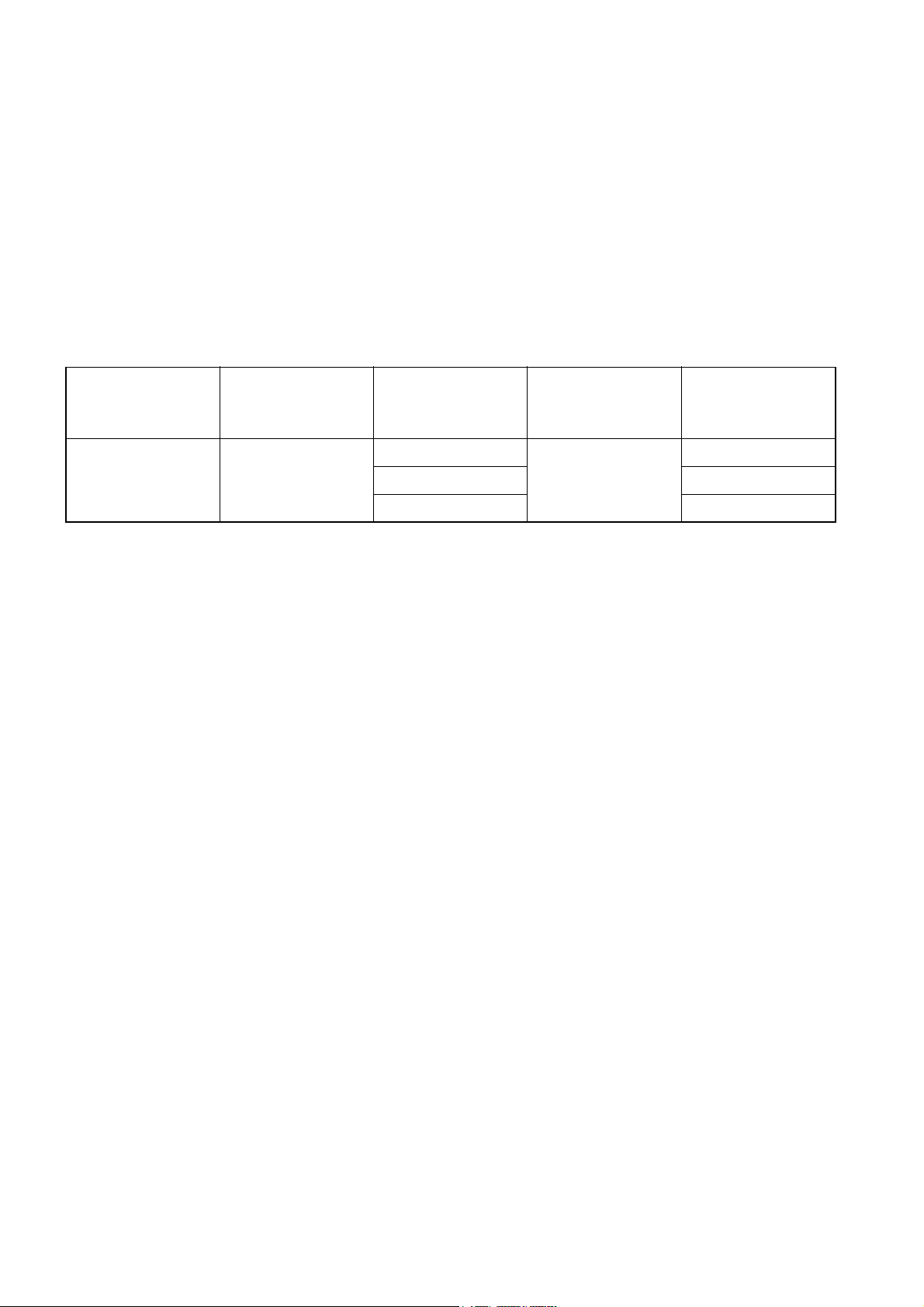
Main Elements
Manufacturer Vehicle Model Engine Model
6HK1
ISUZU Forward
6SD1 9,800
6WG1 15,600
Cylinder
Configuration
Straight 6
Total
Displacement
(cc)
7,800
0
Page 3
1. Outline
1.1 System Outline
This system also provides the following functions:
• A self-diagnosis and alarm function using computer to diagnose the system’s major
components and alert the driver in the event of a problem.
• A fail-safe function to stop the engine, depending upon the location of the problem.
• A backup function to change the fuel regulation method, thus enabling the vehicle to
continue operation.
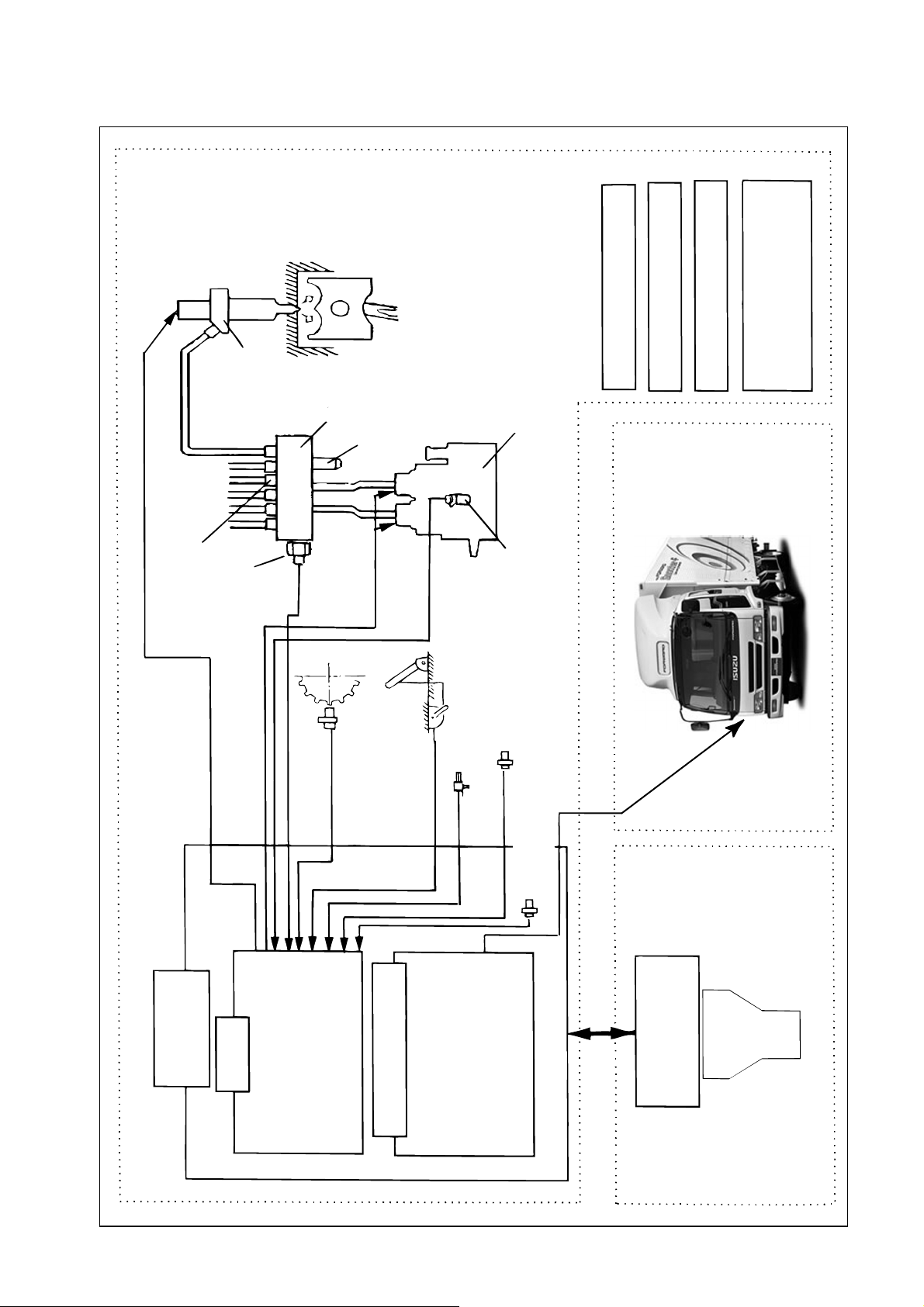
1.2 System Configuration
Divided by function, the system can be classified according to the fuel system and the control
system.
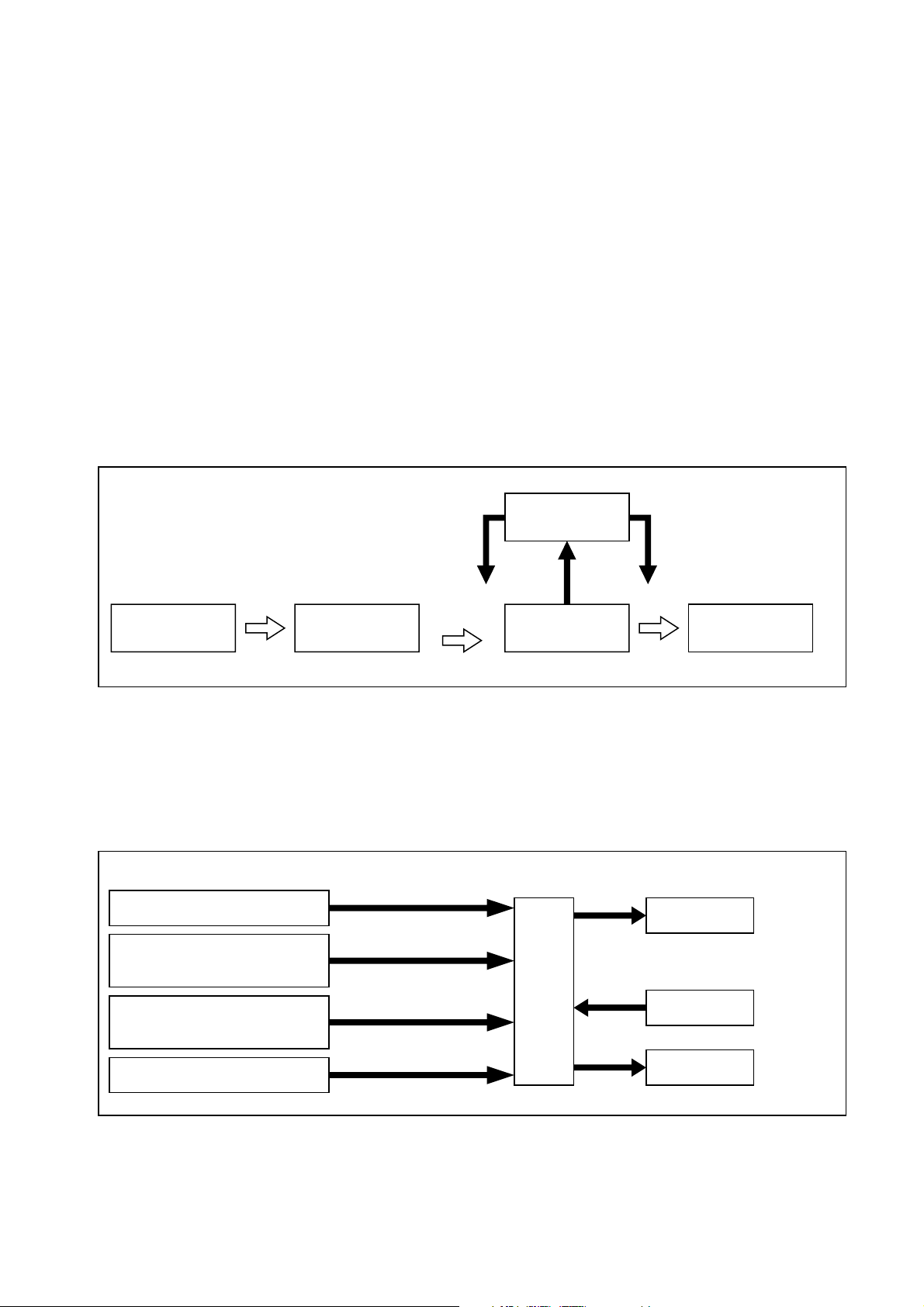
[1] Fuel System
High-pressure fuel that is generated by the supply pump is distributed to the cylinders using a
rail. Electromagnetic valves in the injectors then open and close the nozzle needle valve to control the start and end of fuel injection.
Electronic
control
Solenoid valve to control
the needle lift
Discharge
Fuel tank Supply pump Rail
volume
Injector
Q000080E
[2] Control System
Based on the signals received from various sensors mounted on the engine and the vehicle,
the ECU controls current timing and the duration in which the current is applied to the injectors,
thus ensuring an optimal amount of fuel is injected at an optimal time.
The control system can be broadly classified according to the following electronic components:
sensors, computers, and actuators.
Sensors Computers Actuators
Accelerator sensor
NE sensor
(Crankshaft position sensor)
TDC sensor
(Cylinder recognition sensor)
(Accelerator opening)
(Engine speed)
Cylinder
( )
recognition signal
ECU
Injectors
Fuel injection quantity
( )
and injection timing control etc.
Rail
Other sensors and switches
Supply pump
(Fuel pressure control)
1
Q000081E
Page 4
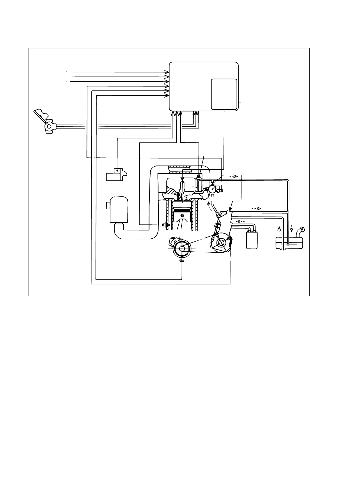
[3] System Configuration (1)
Signals from
switches
ACCP
ECU
Charge-up
circuit
Accelerator position
sensor
Starter signal
Air cleaner
STA
THW
Water temp. sensor
THL
NE sensor
Fuel temp.
sensor
Leak pipe
Rail
Flow damper
Pressure limiter
Supply
pump
Fuel filiter
TDC sensor
Fuel tank
Q000082E
2
Page 5
[4] System Configuration (2)
(inside Head Cover)
Injector
Injection Rate Control
Injection Quantity Control
Injection Timing Control
Injection Pressure Control
(Pressure Control in Rail)
Flow Damper
Rail Pressure sensor
Rail
Pressure Limiter
Crank Position
Sensor (NE Sensor)
Supply Pump
Cylinder Recognition
Sensor (TDC Sensor)
Accelerator Position
Sensor
Coolant Temperature Sensor
Atmospheric Air Temperature Sensor
·
·Fuel Temperature Sensor
·
Boost Pressure Sensor
ECU
Fuel
Injection
·Injection Quantity Control
·Injection Pressure Control
·Injection Timimg Control
Vehicle
Engine
Atmospheric Air
·A/T Control
·Exhaust Break Control
·Engine Shut-down control
·TECHΤ COMMUNICATION
3
(inside ECU)
Pressure Sensor
Communication
(Scan Tool)
Service Tool
TECHΤ
(Dealer)
Q000083E
Page 6
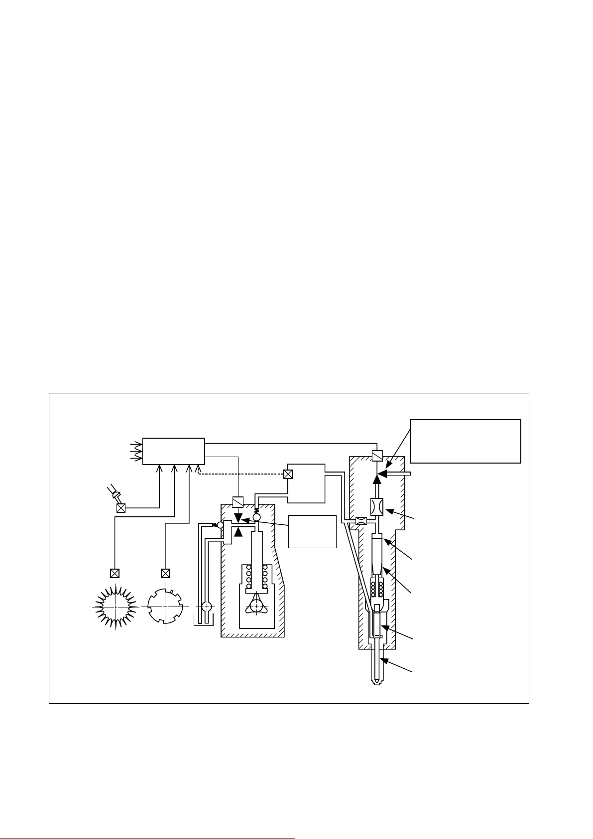
1.3 Construction and Operation of the System
The rail system is comprised of a supply pump, a rail, and injectors, and also includes an ECU
and sensors to regulate those components.
The supply pump generates the internal fuel pressure in the rail. Fuel pressure is regulated by
the quantity of fuel discharged by the supply pump. In turn, the fuel discharge quantity is regulated by electronic signals from the ECU that turn the PCVs (pump control valves) ON and OFF.
Upon receiving fuel pressurized by the supply pump, the rail distributes the fuel to the cylinders.
The pressurized fuel is detected by the rail pressure sensor (installed in the rail) and undergoes
feedback control so that actual pressure will match the command pressure (designated according to the engine speed and load).
Pressurized fuel in the rail passes through the injection pipes that lead to the cylinders, and applies
pressure to the injector nozzles and the control chamber.
The injector regulates injection quantity and timing by turning the TWV (two-way valve) ON and OFF.
When the TWV is ON (current applied), the fuel circuit switches over, causing the high-pressure
fuel in the control chamber to flow out via the orifice. As a result, the force of the high-pressure
fuel at the nozzle valve opening causes the needle valve to lift, thus starting the injection of fuel.
When the TWV is turned OFF (current not applied), the fuel circuit switches over so that highpressure fuel, traveling via the orifice, is introduced to the control chamber. As a result, the needle valve lowers, thus ending the injection of fuel.
Thus, through electronic control, the timing of the current applied to the TWV determines the
injection timing, and the duration in which current is applied to the TWV determines the injection
quantity.
Additional information
(temperature, pressure)
Engine load
ECU
TWV control pulse
Rail pressure sensor
Supply Pump
Rail
Injection
pressure
control
Injector
TWV
· Injection quantity control
· Injection timing control
· Injection rate control
Leak
Orifice
Control chamber
Hydraulic piston
Nozzle
Needle
Q000084E
4
Page 7
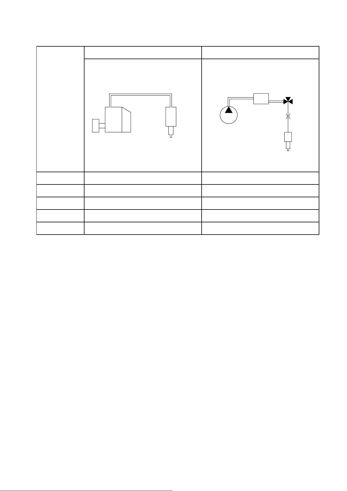
1.4 Comparison to Conventional Pump
Inline Type Common Rail System
System
Injection quantity
regulation
Injection timing
regulation
Distribution of
generated pressure
Distribution
Injection pressure
regulation
Pipe
Instantaneous high
pressure
Timer
Governor
Pump
Pump (governor)
Pump (timer)
Pump
Pump
(Dependent on engine speed and injection volume)
Nozzle
Rail
Constant high
pressure
Supply pump
Injector
ECU, injector (TWV)
ECU, injector (TWV)
Supply pump
Rail
Supply pump (PCV)
Q000085E
5
Page 8

2. Construction and Operation of Components
2.1 Supply Pump [1] Outline
The function of the supply pump is to regulate the fuel discharge volume, thus generating internal
fuel pressure in the rail.
[2] Construction
The supply pump consists of a feed pump, similar to that of the conventional in-line pump, and
the PCVs (pump control valves), provided at each cylinder, to regulate the fuel discharge volume.
The supply pump uses a three-lobe cam to reduce the number of engine cylinders supplied by
the pump to one-third (e.g. a two-cylinder pump for a six-cylinder engine). Furthermore,
smooth and stable rail pressure is obtained because the rate at which fuel is pumped to the rail
is the same as the injection rate.
PCV (Pump Control Valve)
Feed pump
Gear of TDC sensor
6
3-lobe cam
Q000086E
Page 9

[3] Operation
A: The PCV remains open during the plunger’s downward stroke, allowing low-pressure fuel to
be drawn into the plunger chamber by way of the PCV.
B: If the valve remains open because current is not applied to the PCV, even after the plunger
begins its upward stroke, the fuel that was drawn in returns via the PCV, without being pressurized.
C: When current is applied to the PCV in order to close the valve at the timing that accommo-
dates the required discharge volume, the return passage closes, causing pressure in the
plunger chamber to rise. The fuel then passes through the delivery valve (check valve) to the
rail. As a result, an amount of fuel that corresponding to the plunger lift after the PCV closes
becomes the discharge volume, and varying the timing of the PCV closure (plunger prestroke) varies the discharge volume, thus regulating rail pressure.
A’: After surpassing the maximum cam lift, the plunger begins its downward stroke, causing
pressure in the plunger chamber to decrease. At this time, the delivery valve closes, thus
stopping the pumping of the fuel. In addition, because current to the PCV valve is cut off, the
PCV opens, allowing low-pressure fuel to be drawn into the plunger chamber. Thus, the
pump assumes condition “A”.
Cam lift
PCV
operation
Pump operation
PCV
Plunger
Discharge
Suction process Delivery process
Pre-stroke
Valve
closed
A B C A'
Valve open
Delivery valve
Increasing
dischargevolume
Reducing discharge volume
φd
Discharging required
dischrge volume
Rail
volume
Q=
πd
2
(H-h)
4
h
H
Q000087E
7
Page 10

[4] PCV (pump control valve)
The PCV regulates the volume of fuel discharged by the supply pump in order to regulate rail
pressure. The volume of fuel discharged by the supply pump to the rail is determined by the
time at which current is applied to the PCV.
PCV relay
PCV
Key switch
+B
PCV1
PCV2
ECU
Q000088E
[5] Trochoid Type Feed Pump
The feed pump, which is housed in the supply pump, draws fuel up from the tank and delivers
it to the chamber via the fuel filter. The feed pump rotor is driven by the camshaft.
The rotation of the camshaft causes the outer and inner rotors to rotate. At this time, the suction
port side pump chamber volume (the space surrounded by the outer and inner rotors) increases
gradually, causing the fuel entering from the fuel inlet to be drawn into the pump chamber via
the suction port. Along with the rotation of the rotor, the fuel that has been drawn in moves towards the discharge port and is discharged. The discharged fuel travels via the fuel outlet and
is fed into the supply pump body.
Volume decreased
(while moving to discharge port)
Outer rotor
Suction
port
From fuel tank
To pump chamber
Inner rotor
Discharge port
Volume increased
(while drawing in fiel)
[6] Coupling
The coupling is an intermediary device that transmits
the engine driving torque to the supply pump camshaft.
Volume decreased
(while discharging fuel to discharge port)
Volume increased
(while drawing in fiel)
Q000090E
Coupling
Q000091E
8
Page 11

2.2 Common Rail [1] Construction
The functionof the rail is to distribute the high-pressure
fuel pressurized by the supply pump to each cylinder
injector.
The rail pressure sensor, flow damper, and pressure
limiter are mounted on the rail.
Flow damper
A fuel injection pipe is attached to the flow damper to
deliver high-pressure fuel to the injector.
The pressure limiter piping is routed back to the fuel tank.
[2] Flow Damper
The flow damper reduces pressure pulsation in the
high-pressure pipe, thus delivering fuel to the injectors
at a stable pressure. Furthermore, in the event an excessive flow of fuel, the flow damper shuts off the fuel
passage, thus preventing the abnormal fuel flow.
When abnormal amount of fuel flows the high-pressure is applied to the piston. As shown in the illustration, this causes the piston and ball to move right, until
the ball reaches the seat and closes the fuel passage.
Pail pressure sensor
Stopped
During damping
During abnormal flow such as
excessive injection volume
Piston
Pressure limiter
Q000092E
Ball
Seat
Q000093E
[3] Pressure Limiter
The function of the pressure limiter is to dispel abnormally
high pressure by opening its valve to release pressure.
The pressure limiter operates (opens the valve) when
rail pressure reaches approximately 140MPa.
Then, when the pressure decreases to approximately
30MPa, the pressure limiter resumes (closes the valve)
its function to maintain pressure.
NOTE:
Do not attempt to remove or to reinstall the flow damper, pressure limiter, or rail pressure
sensor.
Pc
Q000094E
9
Page 12

[4] Rail Pressure Sensor
The rail, the rail pressure sensor is mounted on the rail and detects the fuel pressure. It is a
semi-conductor type of pressure sensor that utilizes the properties of silicon to change its electrical resistance when pressure is applied.
A-VCC
VPC
A-GND
VPC
ECU
+5V
5
4
3
2
1
Output voltage (V)
0
50 100 150
Pressure PC (MPa)
Q000095E
2.3 Injector [1] Outline
The function of the injector is to inject high-pressure fuel from the rail into the engine combustion chamber at the proper timing, quantity, ratio, and atomization, in accordance with signals
from the ECU.
The TWV (two-way solenoid valve) regulates pressure in the control chamber in order to control
the beginning and end of injection.
The orifice restrains the opening speed of the nozzle valve to regulate the injection ratio.
The command piston transmits pressure from the control chamber to the nozzle needle valve.
The nozzle atomizes the fuel.
Start of Injection (TWV ON)
Rail pressure sensor
ECU
Supply pump
Injection pressure
control
Rail
TWV
Leak
Orifice
Control chamber
Command piston
Nozzle
End of Injection (TWV OFF)
Rail pressure sensor
ECU
Supply pump
Injection pressure
control
Rail
TWV
Leak
Orifice
Control chamber
Command piston
Nozzle
10
Q000096E
Page 13

[2] Construction
The injector consists of the nozzle portion (similar to that of the conventional type), the orifice
(which regulates the injection ratio), the command piston, and the two-way solenoid valve
(TWV).
Upper body
O-ring
TWV
O-ring
Nozzle
Retaining nut
Orifice 2
Orifice 1
Command piston
Lower body
Guide bushing
Washer
Spring
Pressure pin
Tip packing
11
Q000097E
Page 14

[3] Operation
The TWV portion of the injector consists of two valves, an inner valve (fixed) and an outer valve
(movable). Both valves are precision-fitted on the same axis. The valves respectively form inner
and outer seats, and either of the seats opens selectively depending upon whether the TWV is
ON or OFF.
a. No Injection
When no current is applied to the solenoid, the valve spring and hydraulic pressure forces
push the outer valve downward, causing the outer seat to remain closed. Because the rail
high pressure is applied to the control chamber via the orifices, the nozzle remains closed
without injecting fuel.
b. Begin Injection
When current is applied to the TWV, the solenoid force pulls the outer valve upward, causing
the outer seat to open.
As a result, fuel from the control chamber flows out via the orifice, causing the needle to lift
and to start fuel injection. Furthermore, the injection ratio increases gradually in accordance
with the movement of the orifice. As the application of current continues to apply, the injector
reaches its maximum injection ratio.
c. End Injection
When current to the TWV is cut off, the valve spring and hydraulic force (fuel pressure) cause
the outer valve to descend and the outer seat closes. At this time, high-pressure fuel from the
rail is immediately introduced into the control chamber, causing the nozzle to close suddenly.
As a result, injection ends swiftly.
Inner valve
Outer valve
Outer seat
Orifice 2
Orifice 1
Rail
(constant high pressure)
18-130 MPa
Command piston
Nozzle
Control chamber
No Injection Begin Injection End Injection
Q000098E
12
Page 15

[4] Circuit Diagram
COMMON2
ECU
Constant current
circuit
COMMON1
2WV #1 (1st cylinder)
2WV #2 (5th cylinder)
2WV #3 (3rd cylinder)
2WV #4 (6th cylinder)
2WV #5 (2nd cylinder)
2WV #6 (4th cylinder)
Constant current
circuit
Charging circuit
Q000099E
WARNING:
High voltage is applied to the wires connected to COMMON1, COMMON2, and the TWV
#1-#6 terminals of the ECU. Exercise extreme caution to prevent electric shock.
13
Page 16

2.4 Sensors and Relays [1] NE Sensor (crankshaft position sensor)
When the signal holes on the flywheel move past the
sensor, the magnetic line of force passing through the
coil changes, generating alternating voltage.
The signal holes are located on the flywheel at 7.5-degree
intervals. There are a total of 45 holes, with holes missing
in three places. Therefore, every two revolutions of the
engine outputs 90 pulses.
This signal is used to detect the engine speed and the
crankshaft position in 7.5-degree intervals.
[2]
TDC sensor (cylinder recognition sensor)
Similar to the NE sensor, the sensor utilizes the alternating
voltage generated by the changes in the magnetic line of
force passing through the coil.
The disc-shaped gear located in the center of the supply
pump camshaft has a cog (U-shaped cutout) at 120-degree
intervals, plus one tooth in an additional location. Accordingly, every two revolutions of the engine outputs seven
pulses. The combination of the NE pulse, TDC pulse is recognized as the No. 1 cylinder reference pulse.
NE (crankshaft angle) sensor
Q000100E
TDC (cylinder recognition) sensor
Q000101E
A combination of the NE pulse and the TDC pulses are
used for the cylinder reference pulse, and the irregular
pulse is used to determine the No. 1 cylinder.
No.6 cylinder TDC pulse
0°CR 120°CR 240°CR 360°CR 480°CR 600°CR 720°CR
Aux. NE pulse
NE pulse
#1 TDC #5 TDC #3 TDC #6 TDC #2 TDC #4 TDC #1 TDC
75°CR 75°CR 75°CR 75°CR 75°CR 75°CR 75°CR
02468101214
024681012140246
8
0246810121402468101214
10
12
TDC
NE
No.1 cylinder TDC pulse
No.1 cylinder recognition pulse
105°CR
024681012
0246
ECU
Input circuit
Input circuit
Q000102E
8
No.1 cylinder NE reference pulse
No.6 cylinder NE reference pulse
Q000103E
14
Page 17

[3] Water Temperature Sensor (THW made another
manufacturer)
The water temperature sensor detects the temperature
of the engine coolant water and outputs it to the ECU.
The sensor uses a thermistor, which varies resistance
according to temperature. As the ECU applies voltage
to the thermistor, it uses a voltage resulting from the
division of the computer internal resistance and the
thermistor resistance to detect the temperature.
Q000104E
VTHW
A-GND
ECU
VTHW
+5V
5
4
3
2
1
Output voltage (V)
0
-40 -20 0 20 40 60 80 100 120 THW
Coolant temperature (°C)
Q000105E
[4] Fuel Temperature Sensor (THL)
The fuel temperature sensor detects the fuel temperature and outputs it to the ECU. The sensor
uses a thermistor, which varies resistance according to temperature. As the ECU applies voltage to the thermistor, it uses a voltage resulting from the division of the computer internal resistance and the thermistor resistance to detect the temperature.
VTHL
ECU
VTHL
+5V
5
4
3
A-GND
Output voltage (V)
15
2
1
-40-20 0 20406080100120 THL
0
Fuel temperature (°C)
Q000106E
Page 18

[5] Accelerator Position Sensor
This sensor converts the angle of the pedal effort applied to the accelerator pedal into electrical
signals and sends them to the ECU. The accelerator sensor uses hall elements. A magnet is
mounted on the shaft that moves in unison with the accelerator pedal, and the magnetic field
orientation changes with the rotation of the shaft. The changes in the magnetic field orientation
generate voltage.
ECU
Hall elements
(2 pieces)
Magnets
(1 pair)
A-Vcc
VACCP1
A-GND
Amplifier
No. 1
A-Vcc
VACCP2
A-GND
Amplifier
No. 2
+5V
+5V
VAccp1
VAccp2
(V)
[6] Idle Set Button (made by another manufacturer)
A control knob is installed within reach of the driver,
enabling the driver to set the idle rpm. It increases idle
rpm using the idle-up switch, and decreases idle rpm
to the normal rate using the idle-down switch.
4.0
3.0
2.0
1.0
V
0
IGt
50 100
Accelerator opening (%)
Accp
Idle-up switch
Idle-down switch
Q000107E
ECU
Q000108E
[7] Main Relay
To supply current to the ECU, the main relay points close when current is applied to the main
relay coil.
[8] PCV Relay
The PCV relay supplies current to the supply pump PCV (discharge volume control valve).
16
Page 19

3. Various Types of Control
This system controls the fuel injection quantity and injection timing more optimally than the mechanical
governor or timer used in conventional injection pumps.
For system control, the ECU makes the necessary calculations based on signals received from
sensors located in the engine and on the vehicle in order to control the timing and duration in
which current is applied to the injectors, thus realizing optimal injection.
[1] Fuel Injection Rate Control Function
The fuel injection rate control function controls the ratio of the quantity of fuel that is injected
through the nozzle hole during a specified period.
[2] Fuel Injection Quantity Control Function
The fuel injection quantity control function, replaces the conventional governor function, and
controls fuel injection to achieve an optimal injection quantity based on the engine speed and
the accelerator opening.
[3] Fuel Injection Timing Control Function
The fuel injection timing control function, replaces the conventional timer function, and controls
the fuel injection to achieve an optimal injection timing according to the engine speed and the
injection quantity.
[4] Fuel Injection Pressure Control Function (Rail Pressure Control Function)
The fuel injection pressure control function (rail pressure control function) uses a rail pressure
sensor to measure fuel pressure, and feeds this data to the ECU to control the pump discharge
quantity.
Pressure feedback control is implemented to match the optimal quantity (command quantity)
set according to the engine speed and the fuel injection quantity.
Input signal
Accelerator sensor
NE sensor
(Crankshaft position sensor)
TDC sensor
(Cylinder recognition sensor)
Rail pressure sensor
Various sensors
·Coolant temperature sensor
·Fuel temperature sensor
·Atmospheric air temperature
sensor etc.
Fuel control computer
(ECU)
Atmospheric air
pressure sensor
Control output
Fuel injection rate control
Fuel injection quantity control
Fuel injection timing control
Fuel injection pressure control
Diagnosis
17
Q000109E
Page 20

3.1 Fuel Injection Rate Control [1] Main Injection
Same as conventional fuel injection.
[2] Pilot Injection
Pilot injection is the injection of a small amount of fuel
Pilot injection
Main injection
prior to the main injection.
While the adoption of higher pressure fuel injection is
associated with an increase in the injection rate, the
lag (injection lag) that occurs from the time fuel is injected until combustion starts cannot be reduced be-
Q000110E
low a certain value. As a result, the quantity of fuel
injected before ignition increases, resulting in explosive combustion together with ignition, and
an increase in the amount of NOx and noise. Therefore, by providing a pilot injection, the initial
injection rate is kept to the minimum required level dampening, the explosive first-period combustion and reducing NOx emissions.
TDC
Combustion
process
Injection rate
Heat generation
rate
High injection
rate
Large pre-mixture
combustion
(NOx, noise)
Ignition delay
Delta injection
Small injection amount
prior to ignition
Pilot injection
Improvement
Small pre-mixture
combustion
Q000111E
[3] Split Injection
When the rotation is low at starting time, a small
amount of fuel is injected several times prior to main
injection.
18
Split injection
Q000112E
Page 21

4. Reference
4.1 Diagnosis Code
Failure Mode Diagnosis Light Pattern
NE sensor system
Aux. NE sensor system
Rail abnormal high pressure (Sensors’ failure)
Rail pressure sensor output is abnormally
constantly
Rail abnormal pressure (overcharged by supply
pump)
Rail abnormal pressure (control system)
Injection quantity adjustment resistor
Coolant temperature sensor
Fuel temperature sensor
Atmospheric air temperature sensor
Accelerator sensor 1
Accelerator sensor 2
Accelerator sensor
Atmospheric air pressure sensor
Starter S/W
Flow damper
TWV driving circuit open
TWV driving circuit short (+B)
TWV driving circuit short (GND)
Supply pump does not send pressurized fuel to
rail, or pressure limiter operates
Supply pump does not send necessary
pressurized fuel due to fuel leakage
PCV system short (+B)
(Coil or harness)
PCV system open/short (GND)
(Coil or harness)
Abnormal A/D convension
ECU
PCV and relay system
Diagnosis
(Light for 20 seconds at 700rpm or less) 15
B
B
(constantly lit up) 245
A
A
A
A
A
(not lighting) 23
C
C
C
A
A
A
C
C
#1: 261
#2: 262
C
#3: 263
#4: 264
#5: 265
#6: 266
#1: 271
#2: 272
A
#3: 273
#4: 274
#5: 275
#6: 276
Common 1system
A
A
Common 2system
Common 1system
Common 2system
A
A
A
A
PCV1: 217
PCV2: 218
PCV1: 247
PCV2: 248
A
A
A
Code
14
115
151
118
34
211
22
24
24
28
71
417
158
159
158
159
226
227
35
—
421
19
Page 22

Failure Mode Diagnosis Light Pattern
Main relay
Boost pressure sensor
Abnormally high boost pressure
Abnormally low boost pressure
Diagnosis
Code
B
C
C
C
416
32
A: 42
B: 32
65
Overrun1 (Software)
Overrun2 (Hardware)
Abnormal output by accelerator sensor1
Abnormal output by accelerator sensor2
Abnormal watch dog timer
Charge circuit failure
C
C
A
A
A
A
—
543
24
24
35
35
20
Page 23

4.2 Circuit Diagram
START
Key "ON" Relay
LOCK
ACC
ON
PCV Relay
12V
Crank Position Sensor
(NE Sensor)
Cylinder Recognition Sensor
(TDC Sensor)
Sensor 1
Accelerator Sensor
Sensor 2
Injection Quantity
Adjustment Resistor
Atmospheric Air
Temperature Sensor
Fuel Temperature
Sensor
Coolant Temperature
Sensor
Main Relay
STA/SW
KEY/SW
KEY/SW
+BP
+BP
M-REL
M-REL
GND
GND
P-GND
P-GND
NE+
NE-
NE-SLD
G+
G-
G-SLD
J1708A
J1708B
ACC1-VCC
ACC2-VCC
ACC1
ACC2
ACC1-GND
ACC2-GND
FQ1
FQ2
FQ3
FQ-GND
THA
THF
THV
TH-GND
PCV1
PCV1
PCV2
PCV2
DIAG-L
DG/SW
COMMON1
COMMON1
COMMON2
COMMON2
TWV1
TWV1
TWV2
TWV2
TWV3
TWV3
TWV4
TWV4
TWV5
TWV5
TWV6
TWV6
AT-REL
EXB-REL
EXB/SW
IDLUP/SW
IDLDWN/SW
TM/SW
N/SW
CL/SW
MCLR/SW
MF AM/SIG
MF AM/USE
Pressure Control
Val ve
Diagnosis Light
Diagnosis S/W
A/T Relay
Exhaust Break
Relay
Idle-up S/W
Idle-down S/W
Transmission S/W
Neutral S/W
Clutch S/W
TWV
Exhaust
Break S/W
Memory Clear S/W
MF AM/SIG
MF AM/USE
Rail Pressure
Sensor
Boost Pressure
Sensor
PFUEL-VCC
PFUEL
PFUEL
PFUEL-GND
A-VCC
PBOOST
A-GND
21
CHECKER
TACHO
Tool Display
Tachometer
Case GND
Q000113E
 Loading...