

Page 1

WORKSHOP MANUAL
727 (N SERIES)
ENGINE CONTROL SYSTEM
(4HL1 ENGINE)
SECTION 1A
International Service & Parts
Tokyo, Japan
Page 2

N O T I C E
Before using this Workshop Manual to assist you in performing
vehicle service and maintenance operations, it is recommended
that you carefully read and thoroughly understand the information
contained in Section - 0A under the headings “GENERAL REPAIR
INSTRUCTIONS” and “HOW TO USE THIS MANUAL”.
All material contained in this Manual is based on the latest product
information available at the time of publication.
All rights are reserved to make changes at any time without prior
notice.
Page 3

Engine Control System 1A-1
ENGINE
Engine Control System
CONTENTS
Engine Control System . . . . . . . . . . . . . . . . . . . . 1A-2
Precautions on Service . . . . . . . . . . . . . . . . . . 1A-2
Function and Operation . . . . . . . . . . . . . . . . . . 1A-3
Powertrain System Components . . . . . . . . . . . 1A-9
Circuit Diagram . . . . . . . . . . . . . . . . . . . . . . . 1A-20
Strategy-Based Diagnostics . . . . . . . . . . . . . . 1A-38
Functional Check List . . . . . . . . . . . . . . . . . . . 1A-44
Hearing Diagnostic . . . . . . . . . . . . . . . . . . . . . 1A-44
On-Board Diagnostic (OBD) System Check . 1A-47
Inactive CHECK ENGINE Lamp Check . . . . . 1A-50
Unblinking CHECK ENGINE Lamp Check . . . 1A-54
ECM Power Supply and Grounding System Circuit
Check . . . . . . . . . . . . . . . . . . . . . . . . . . . . . . . 1A-56
Diagnosis with Tech 2 Scan Tool . . . . . . . . . . 1A-59
Diagnostic Chart . . . . . . . . . . . . . . . . . . . . . . . 1A-88
DTC14 - CMP Sensor System Fault . . . . . . . 1A-93
DTC15 - CKP Sensor System Fault . . . . . . . . 1A-97
DTC18 - Starter Degradation (For Only Vehicles
Equipped with Idle Stop Function) . . . . . . . . 1A-101
DTC22 - IAT Sensor System Fault . . . . . . . . 1A-103
DTC23 - ECT Sensor System Fault . . . . . . . 1A-107
DTC24 - Accelerator Sensor System Fault . 1A-112
DTC25 - Vehicle Speed Sensor System
Fault . . . . . . . . . . . . . . . . . . . . . . . . . . . . . . . 1A-116
DTC28 - PTO Accelerator Sensor System
Fault . . . . . . . . . . . . . . . . . . . . . . . . . . . . . . . 1A-120
DTC31 - Idle Up Volume System Fault . . . . 1A-123
DTC33 - VIM Internal Fault (EEPROM Write
Error) . . . . . . . . . . . . . . . . . . . . . . . . . . . . . . 1A-127
DTC34 - ECM Internal Fault (Charge Circuit
Fault) . . . . . . . . . . . . . . . . . . . . . . . . . . . . . . 1A-129
DTC35 - VIM Internal Fault (A/D Conversion
Fault) . . . . . . . . . . . . . . . . . . . . . . . . . . . . . . 1A-132
DTC43 - ITP Sensor System Fault . . . . . . . . 1A-134
DTC44 - EGR Valve Position Sensor System
Fault . . . . . . . . . . . . . . . . . . . . . . . . . . . . . . . 1A-139
DTC45 - EGR Valve System Fault . . . . . . . . 1A-144
DTC46 - Exhaust Brake System Fault . . . . . 1A-147
DTC51 - ECM Internal Fault (CPU Error / CPU
History Error) . . . . . . . . . . . . . . . . . . . . . . . . 1A-150
DTC52 - ECM Internal Fault
(Sub CPU Error) . . . . . . . . . . . . . . . . . . . . . . 1A-152
DTC61 - Intake Throttle Valve System Fault 1A-154
DTC71 - Barometric Pressure Sensor Fault 1A-157
DTC81 - Clutch Switch System Fault . . . . . . 1A-159
DTC82 - Neutral Switch System Fault . . . . . 1A-163
DTC84 - CAN Communication Fault
(CAN Bus Error) . . . . . . . . . . . . . . . . . . . . . . 1A-166
DTC86 - CAN Communication Fault
(CAN Timeout Error) . . . . . . . . . . . . . . . . . . . 1A-169
DTC115 - Common Rail Pressure Sensor Fixed
Output Fault . . . . . . . . . . . . . . . . . . . . . . . . . 1A-172
DTC1 18 - Common Rail Pressure Fault
(Control System) . . . . . . . . . . . . . . . . . . . . . 1A-177
DTC158 - Injector Power Supply System Short
(Common 1) . . . . . . . . . . . . . . . . . . . . . . . . . 1A-182
DTC159 - Injector Power Supply System Short
(Common 2) . . . . . . . . . . . . . . . . . . . . . . . . . 1A-186
DTC21 1 - Fuel Temperature Sensor System
Fault . . . . . . . . . . . . . . . . . . . . . . . . . . . . . . . 1A-190
DTC217 - SCV Drive System Short . . . . . . . 1A-195
DTC227 - No Pump Pressure Feed (Fuel Leak)
. . . . . . . . . . . . . . . . . . . . . . . . . . . . . . . . . . . 1A-198
DTC241 - Idle Position Switch Circuit Open
Wiring . . . . . . . . . . . . . . . . . . . . . . . . . . . . . . 1A-203
DTC242 - Idle Position Switch Circuit Short . 1A-206
DTC245 - Common Rail Pressure Sensor
System Fault . . . . . . . . . . . . . . . . . . . . . . . . 1A-209
DTC247 - SCV Drive System Fault . . . . . . . 1A-215
DTC271 - Cylinder 1 (Injector Drive System)
Fault . . . . . . . . . . . . . . . . . . . . . . . . . . . . . . . 1A-219
DTC272 - Cylinder 2 (Injector Drive System)
Fault . . . . . . . . . . . . . . . . . . . . . . . . . . . . . . . 1A-223
DTC273 - Cylinder 3 (Injector Drive System)
Fault . . . . . . . . . . . . . . . . . . . . . . . . . . . . . . . 1A-227
DTC274 - Cylinder 4 (Injector Drive System)
Fault . . . . . . . . . . . . . . . . . . . . . . . . . . . . . . . 1A-231
DTC277 - Injector Power Supply System Open
Wiring Fault (Common 1) . . . . . . . . . . . . . . . 1A-235
DTC278 - Injector Power Supply System Open
Wiring Fault (Common 2) . . . . . . . . . . . . . . . 1A-239
DTC416 - Main Relay System Fault . . . . . . . 1A-243
DTC417 - Starter Switch System Fault . . . . 1A-246
DTC543 - High Engine Speed Error . . . . . . . 1A-249
Default Matrix Table . . . . . . . . . . . . . . . . . . . 1A-250
Special Tools . . . . . . . . . . . . . . . . . . . . . . . . 1A-256
Wiring Harness Repair: Shielded Cable . . . . . 1A-257
Removal Procedure . . . . . . . . . . . . . . . . . . . 1A-257
Installation Procedure . . . . . . . . . . . . . . . . . 1A-257
Twisted Leads . . . . . . . . . . . . . . . . . . . . . . . . . 1A-258
Removal Procedure . . . . . . . . . . . . . . . . . . . 1A-258
Installation Procedure . . . . . . . . . . . . . . . . . 1A-258
Weather-Pack Connector . . . . . . . . . . . . . . . . 1A-260
Removal Procedure . . . . . . . . . . . . . . . . . . . 1A-260
Installation Procedure . . . . . . . . . . . . . . . . . 1A-260
Special Tools . . . . . . . . . . . . . . . . . . . . . . . . 1A-261
Com-Pack III . . . . . . . . . . . . . . . . . . . . . . . . . . 1A-262
General Information . . . . . . . . . . . . . . . . . . . 1A-262
Metri-Pack . . . . . . . . . . . . . . . . . . . . . . . . . . . . 1A-263
Removal Procedure . . . . . . . . . . . . . . . . . . . 1A-263
Installation Procedure . . . . . . . . . . . . . . . . . 1A-263
Special Tools . . . . . . . . . . . . . . . . . . . . . . . . 1A-263
Page 4

1A-2 Engine Control System
ngine Control System
E
Precautions on Servic e
Circuit test tools
Unless otherwise specified in diagnostic procedures,
do not use Test Light to diagnose the powertrain
electrical system. When diagnostic procedures need
probe connector, use Connector Test Adapter Kit 58840-0385-0.
On-market electrical equipment and vacuum
devices
On-market electrical equipment and vacuum devices
refer to those components that will be installed to
vehicles after shipme nt from manufacturing plants. Be
careful that installation of these components is not
considered during the process of vehicle design.
CAUTION:
Do not install on-market vacuum devices to
vehicles.
CAUTION:
Connect on-market electrical equipment, as well as
its power supplies and grounds, to the circuits
isolated from the electronic control system.
The on-market electrical equipment, even when
installed to vehicles in normal manner, may bring
functional troubles to the electronic control system.
Affected devices include those not connected to the
vehicle electrical equipment system, for example,
mobile phones or radios. Therefore, when you intend to
diagnose the powertrain, check such the on-market
electrical equipment has not been installed to the
vehicle and, if installed, remove it. If faults still occur
even after removal of on-market electric al equipment,
diagnose the vehicle according to normal procedures.
Damage by electrostatic discharge
Electronic components used in the electronic control
system are designed to w ork at very low volta ges and,
for this reason, they are susceptible to damage by
electrostatic discharge and some types of electronic
components may be damaged even by the static
electricity of less th an 100 V that is us ually not sensed
by persons. Persons’ sensitivity level is 4,000 V.
Persons are electrostatically charged in various ways
and the most typical e lectrification sources are f riction
and induction. Shown below are examples.
• Electrification by friction occurs when a person
slides on the seat in the vehicle.
• Electrification by induction occurs when a person
with insulating shoes is standing near a highly
electrifiable substance and touches a ground
momentarily. Electric charges with the same
polarity flow out and resultantly the person is
charged at high opposite polarity. Since static
electric charges cause damages, it is important
when you handle or test electronic components.
CAUTION:
To prevent damages by electrostatic discharge,
follow the guidelines shown below.
• Do not touch ECM connector pins as well as
electronic components soldered to the ECM
circuit board.
• Do not unpack each replacement component
until preparations are completed for the
component.
• Before taking out a component from the
package, connect the package to the normal
grounding line of the vehicle.
• When you intend to slide on the seat, change
the posture from standing to sitting, or wa lk by
a certain distance to handle a component,
touch an appropriate grounding material.
Wire color
All wiring harnesses are id entifi ed using colored jac ket.
The wiring harness used for the main circuit in an
electrical system is identifi ed with sing le color while t he
wiring harness used for the sub- circu it is i dentif ied with
color stripe. The following rule is used in each wiring
diagram to indicate size and color of a wiring harness.
eg. : 0.5 GRN / RED
1
2
3
LNW21ASH000101-X
Legend
1. Red (stripe color)
2. Green (base color)
3. Harness size (0.5 mm
2
)
Page 5

Engine Control System 1A-3
Symbol Color Symbol Color
BBlackBRBrown
W White LG Light green
R Red GR Gray
GGreenP Pink
Y Yellow LB Light blue
L Blue V Violet
OOrange
Function and Operation
Electronic Control System
The electronic control system processes the data,
which has been collected with various types of sensors,
by means of the control program installed to ECM
(engine control module) to totally control engine
parameters such as fuel injection quantity, injection
timing, engine startup, altitude compensation, and
EGR.
ECM
ECM Description
The ECM is mounted in th e inner part of the engine lef t
side cover. The ECM monitors variou s data sent from
diversified sensors and controls systems in the
powertrain. The ECM diagnoses these systems to
detect faults with respect to system operations and
inform the driver of faulty condition via the CHECK
ENGINE lamp (MIL) and stores DTCs (diagnostic
trouble codes). DTC identifies the trouble generation
area to aid repairs by service operators.
Function of ECM
ECM supplies 5 V and 12 V voltages to various sensors
and switches. Since powers are supplied via high
resistances in EC M, Test Light, even when c onnected
to the circuit, will not be lit. In a special case, a no rmal
voltmeter does not indicate correct values since the
resistance of the ins trument i s too low. To get a ccurate
readings, you need a digital voltmeter whose input
impedance is at least 10 MΩ. The special tool 5-88400366-0 is a proper choice for this measurement. In the
ECM, the output c ircuit is controlled by regulati ng the
grounding system or power circuit via transistor or
either of the devices listed below.
• Output driver module (ODM)
• Quad drive module (QDM)
ECM and Components
The ECM is designed to offer excellent drivability and
fuel economy while achieving exhaust gas emission
control requirements. The ECM monitors engine and
vehicle functions via various electronic sensors such as
CKP (crank position) and VS (vehicle speed) sensors.
Voltages from ECM
The ECM supplies reference voltages to various
switches and sensors. Resistances of the ECM are
very high and this allows the ECM to supply voltages to
these devices, and v oltages actually app lied to circuits
are low and even connecting Test Light to individual
circuits may fail turn-on. Since the voltmeter normally
used in service factories has low input impedance,
correct readings m ay not be obtain ed. To get accurate
readings, a digital voltmet er whose input impedanc e is
10 MΩ (for example, 5-8840-0366-0) should be used.
Input/output devices of the ECM include analog-todigital converter, signal buffer, counter, and special
driver. By using electronic switch es, the ECM controls
most system components and turning off a switch
closes the ground circuit. These switches are divided
into four-switch or seve n- sw itc h gr ou ps, a nd th e former
group is called qu ad driv er mo dul e (Q DM) and controls
up to four output pins respectively while the latter group
is called output driver module (ODM) and controls up to
seven outputs respectively. Note that all the outputs are
necessarily not used in the control.
Electrically Erasable Programmable ROM
(EEPROM)
EEPROM is a permanent memory chip and soldered to
the board in the ECM. EEPROM stores program and
calibration data, both of which are necessary for the
ECM to control the powertrain. Different from
conventional ROMs, EEPROM cannot be replaced with
new component. If EEP ROM fails, the complete ECM
assembly must be replaced with new one.
Precautions on ECM Servic e
The ECM is designed to withstand ordinary currents
used in operations of a vehicle. Be careful that the
circuits must not be overloaded. To test the ECM to
check open wiring or short, ECM circuits must be
connected to the ground or voltages must not be
applied to the ECM. To test ECM circuits, the digital
voltmeter 5-8840-0366-0 should always be used.
Page 6
1A-4 Engine Control System
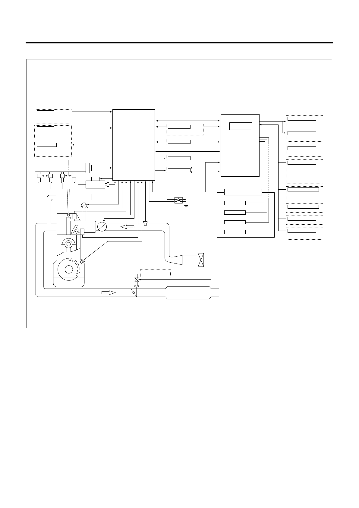
Engine Control System
Accelerator
AP sensor
Idle position switch
Switch
A/C switch
Relay/Lamp
Starter cut relay
Glow relay
Check engine lamp
Common rail
Common rail
Injector
Exhaust
pipe
EGR cooler
pressure sensor
SCV
Supply
pump
EGR valve drive
EGR valve position sensor
CMP sensor
ITP sensor
Intake throttle drive
ECT
FT sensor
ECM
(Engine Control Module)
IAT sensor
CAN
Starter
Ignition switch
Starter switch
Battery
Outer diagnostic unit
Diagnostic switch
Main relay
Battery +
Atomospheric
pressure sensor
VIM
(Vehicle Interface Module)
Vehicle functions
Tachometer
TCM
ABS/ASR ECU
ISS ECU
Relay
ECO Relay,
Exhaust Brake
Lamp
Exhaust Brake Lamp
Glow Lamp
Brake
Stop Lamp Relay
Exhaust Brake Lamp
Transmission
Clutch Switch
Neutral Switch (MT)
Parking
/Neutral (AT)
Switch
Vehicle Speed Sensor
Power Take OFF (PTO)
PTO Switch (
ACTIVE HIGH
ACTIVE LOW
PTO Switch (
PTO Accelerator Sensor
Quick Warm Up System
QWS Switch
Idle
Idle Up Volume
Others
Freezer Switch
Clean Starting Memory
)
)
CKP
Exhaust brake
solenoid valve
The engine control system comprehends vehicle status
and driver’s i ntention based on the data acquired from
sensors and switches to adapt the engine to chang ing
situation so that the vehicle will achieve optimal running
condition. The heart of the engine control system is
ECM and this device provides direct control tasks for
the engine system, including fuel injection control,
intake throttle control , EGR control, and QWS control.
The ECM also governs vehicle system control
strategies such as ex haust brake control and id le stop
control via VIM. In addition, the ECM communicates
with other key systems, including ABS/ASR system
and clutch free system, via VIM.
LNW21ALF004601-X
Page 7
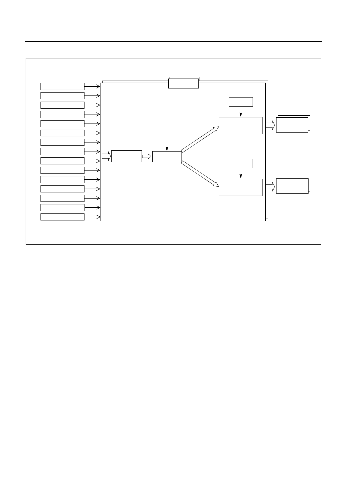
Fuel Injection Control
Engine Control System 1A-5
DTC Detection Status
Battery Voltage
Key Switch Position
Engine Speed
Vehicle Speed
Engine Coolant Temp.
Intake Air Temp.
Fuel Temp.
Common Rail Pressure
Accelerator Pedal Position
Idle Position Switch
Clutch Switch
Neutral Switch
PTO Switch
Idle Stop
Status Judge
Compensation
Desired Injection
Quantity
Determine
ECM
Compensation
Injector
Energize Time/
Timing Determine
Compensation
SCV Position
Determine
Injector
Control
SCV
Control
LNW21AMF005601-X
The fuel injecti on con t rol system manages the i nje ct ion
quantity, injection timing, and injection pressure
according to the status of vehicle. This system changes
the injection quantity using injector operating period,
the injection timing using injector operation timi ng, and
the injection pressure using SCV drive duty,
respectively. The fuel injection co nsists of two stages,
pilot injection and main injection, and the control
system changes the amount and timing in individual
stages according to the conditions encountered.
The ECM uses the data acquired from associated
sensors and switches to judge the current vehicle
status, i.e., startup, idling, PTO, or idle stop, and
calculate the desired injection quantity. Once the
desired injection quantity is determined, ECM
calibrates the value to determine injector energize time,
energize timing, and SCV opening and controls
injectors and the SCV accordingly.
Calculation of Desired Injection Quantity
The ECM calcu lates the basic injecti on quantity using
engine speed, accelerator pedal position, engine
coolant temperature, a nd other necessary parameters
and calibrates this value based on the atmospheric
pressure or the li ke to determine the desire d injection
quantity.
Injector Control
The injector control consists of four stages: "control
stop mode" where the fuel injection is completely
stopped, "split injection mode" where two (or more)
injection shots are mad e for one cylinder at low engine
speeds and temperatures, "fixed injection mode" where
only main injectio n is made at ve ry low engine sp eeds
during startup, and "normal in jection mode" where the
fuel injection is made within normal engine speed
range. The proper mo de is selecte d according to s uch
the parameters as engine speed, engine coolant
temperature, and DTC. The ECM uses the desired
injection quantity, intake air temperature, engine
coolant temperature, and other parameters to
determine injector energize period (desired injection
period) and injector energize timing (desired injection
timing) and control i njectors according to the injec tion
mode selected.
SCV Control (Pump Control)
Pumps are controlled in six stages: "shutoff mode",
"start mode", "wait mode", "restart mode", "feedback
mode", and "deflate mode". The proper mode is
selected according to such the parameters as key
switch position, common rail pressure, and engine
speed. The ECM calcu lates desired injecti on pressure
and pump flow rate for the selected mode based on
intake air temperature, engine coolant temperature,
engine speed, desired injection quantity, and other
necessary parameters. Then , the ECM determines the
SCV opening (SCV drive duty) us ing thes e result s and
controls the SCV.
Page 8
1A-6 Engine Control System
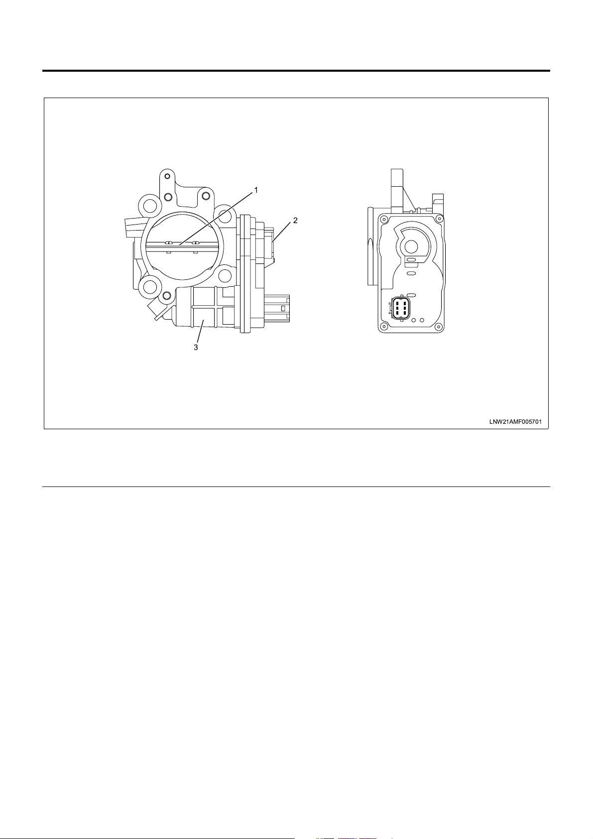
Intake Throttle Control
3
1
2
Legend
1. Intake throttle valve
2. ITP (intake throttle position) sensor
The intake throttle control system changes (throttles)
the air according to the vehicle status and reduces
suction noises generated from the working exhaust
brake and acceleration. This control is made by
opening and closing the intake throttle valve. The
intake throttle valve is ope rated by the DC motor and
changing the drive voltage (duty: see Note 1) opens
and closes the v alve. The intake throttle valve i s fully
opened in the normal state (i.e., the DC motor is
inactive) and gradually reduces the opening as the
drive voltage is increased. The ECM uses the ITP
(intake throttle position) sensor to detect the working
condition of the intake throttle valve. When the valve
opening gets smaller (the drive voltage is increased),
the output voltage of the ITP sensor becomes lower.
The valve position is norm ally calculated using engine
coolant temperature, engine speed, and desired
injection quantity, and the DC motor drive voltage is
determined from this calculated value. However, the
ECM completely opens the throttle valve when the
vehicle is in idle stop, DTC is set for the intak e throttle
system, AP sensor system, or EGR system, gear
shifting is perfo rmed (for m anual trans missi on ve hicle ),
the engine coolant temperature is low (less than 70°C),
or the vehicle is i n startup or en gine s tall sta tus wh ile i t
completely close s the valve immediately after the key
LNW21AMF005701
3. Intake throttle DC motor
switch is turned off (within 0.5 to 3.0 seconds).
There is an opposing relationship between intake
throttle control and EGR control. When the intake
throttle valve is opened, the EGR valve is closed, and
vice versa.
Note 1: Duty (%) = Energize ratio
Page 9
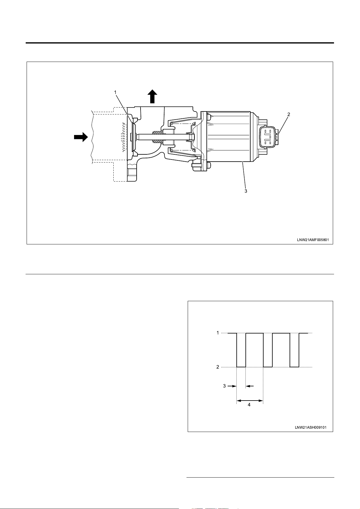
EGR Control
Engine Control System 1A-7
1
2
3
Legend
1. EGR valve
2. EGR valve position sensor
The EGR control system recirculates a portion of
exhaust gas to the intake to drop the combustion
temperature and thus reduce NOx. This control is
made by opening and closing the EGR valve. The EGR
valve is operated by the DC motor and changing the
duty (see Note 1) opens and closes the valve. This
EGR valve is f ully closed in the nor mal state (i.e., the
DC motor is inactive) and gradually enlarges the
opening as the duty is increased. The ECM uses the
EGR valve posit ion sens or to com prehend the working
condition of the EGR valve. When the valve opening
gets larger (the duty is increased), the output voltage of
the EGR valve position sensor becomes higher.
The EGR control is initiated when parameters such as
engine speed, engine coo lant temperatu re, acce lerator
position, atmospheric pressure, and system voltage
meet the required conditions, and the EGR valve
opening is calculated from engi ne c oolan t t emp eratur e ,
engine speed, and desire d inje ction quanti ty. The ECM
determines the drive duty of the DC motor based on
this valve position and drives the motor. The EGR
control is turned off when the exhaust brake is
operated, the PTO is working, the A P sensor fails, the
ECT sensor fails, the EGR system fails, or th e intake
throttle system fails.
There is an opposing relationship between EGR control
and intake throttle control. When the intake throttle
valve is opened, the EGR valve is closed, and vice
versa.
LNW21AMF005801
3. EGR DC motor
Note 1: Duty (%) = T (*) / 5 (msec) × 100
* T = Duty input time (see motor drive voltage
waveform)
1
2
3
4
LNW21ASH009101
Legend
1. 24V
2. 0V
3. T (duty input time)
4. 5 msec
Page 10

1A-8 Engine Control System
QWS Control
The QWS (quick warm- up system) curtails the engine
warm-up time. The glow control covers the engine
warm-up during the period from pre-startup to
immediate completion of startup. The QWS works
when the vehicle meets the required conditions after
engine startup and the dr iv er tu rn s o n th e Q WS s wit ch ,
and lasts until the vehicle deviates from the QWS
working conditions.
QWS working conditions
• The engine coolant is less than 73°C.
• The engine is running at or above 40 0 rpm for at
least 0.5 second.
• Both EGR and PTO controls are disabled.
• The vehicle is free from AP sensor fault, ECT
sensor fault, A/D conversion fault, idle position
switch fault, clutch switch fault, neutral switch fault,
and vehicle speed sensor fault.
• The difference between actual and desired eng ine
speeds is less than 50 rpm.
• The desired engine speed is less than 1000 rpm.
• The vehicle is being off.
• The state where the starter switch is turned off and
the idle position switch is turned on lasts for at
least 0.5 seconds.
Exhaust Brake Control
A valve is instal le d ins id e t he exhaust pipe. Closing this
valve increases the resistance during the exhaust
stroke to enhance the effect of engin e brake. T he drive
source of the exhaust brake valve is vacuum. A
solenoid valve is inst alled to control the vacuum. The
exhaust brake is contr olled by o pening and clo sing this
solenoid electrically. When the engine is running at or
above 500 rpm, the e xhaust cut command is no t sent
from the automatic transmi ssion, and exhaust brake or
QWS working co nditions are completely me t, the VIM
turns on the solenoid valve.
• For a manual transmission vehicle, the clutch
pedal is not pressed. For an automatic
transmission veh icle, the exhaus t brake co mmand
is not sent from the automatic transmission.
• The system voltage stays between 20 V and 30 V .
Idle Stop Control (for Vehicles Equipped with Idle
Stop Control System)
The idle stop control system automatically cuts the
engine to prevent t he black smoke emission f rom the
vehicle that is not running for unloading or other works
(to restart the engine, manual operation is needed).
When all the idle stop conditions are met, the ECM
stops fuel injection and actuate s energy-saving relays
to turn off wipers, mirror defoggers, flashers, seat
heaters, and other electrical equipment.
Idle Stop Control Working Conditions
• The driver fails to apply the parking brak e and the
signal is input from the alarm unit. (Note 1)
• The vehicle ran at or above 5 km/h.
• The vehicle is idling.
• The vehicle speed is 0 km/h.
• The shift lever is in the neutral position.
• The QWS switch is turned off.
• The engine coolant temperature is at least 10°C.
• The battery voltage is at least 22 V.
• DTC has not been detected.
Note 1: When all the following conditions are met, the
parking brake disengagement alarm unit outputs the
idle stop permit signal to the VIM.
• The idle stop main switch is turned on.
• The shift lever is in the neutral position.
• The parking brake is applied.
• The headlamps are turned off.
• Any of doors is opened.
Exhaust Brake Working Conditions
• The vehicle is running at or abo ve 5 km/h or faults
are not detected on the vehicle speed sensor.
• The exhaust brake switch is turned on.
• The engine is running at or above 50 0 rpm for at
least 1 second.
• The idle position switch is turned on and the gear
is engaged.
• The vehicle is not eq uipped with ABS/ASR or the
exhaust brake cut command is not sent from the
ASR.
• The vehicle is free from AP sensor fault, exhaust
brake circuit fault, clutch switch fault, neutral
switch fault, idle position switch fault, A/D
conversion fault (VIM), and CAN timeout (VIM).
Page 11
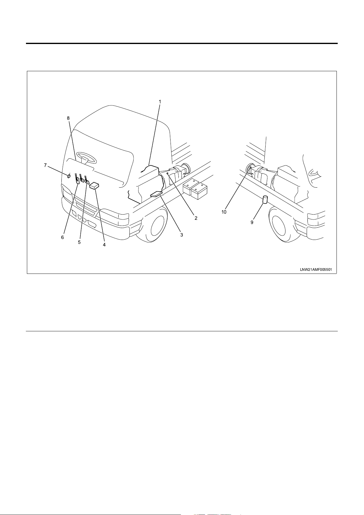
Powertrain System Components
Component Layout - Vehicle Side
8
7
Engine Control System 1A-9
1
6
5
4
Legend
1. Engine
2. Neutral switch
3. ECM (engine control module)
4. VIM (vehicle interface module)
5. Clutch pedal
2
10
3
6. Accelerator pedal
7. DLC (data link connector)
8. CHECK ENGINE lamp (MIL)
9. Exhaust brake solenoid valve
10. VS (vehicle speed) sensor
9
LNW21AMF005501
Page 12
1A-10 Engine Control System
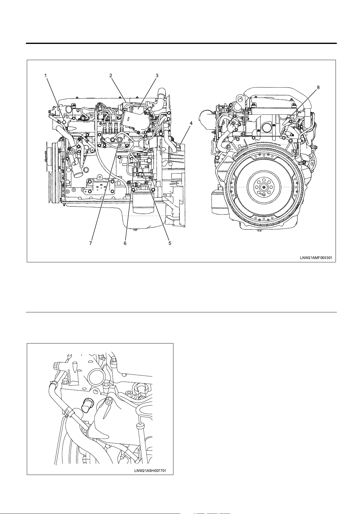
Component Layout - Engine Side
123
8
4
67
Legend
1. ECT (engine coolant temperature) sensor
2. EGR valve
3. Intake throttle valve
4. CKP (crank position) sensor
Function and Operation
ECT Sensor
5
LNW21AMF005301
5. FT (fuel temperature) sensor
6. SCV (suction control valve)
7. Common rail pressure sensor
8. CMP (cam position) sensor
The ECT (engine coolant temperature) sensor is
installed to the thermosta t housing and the thermistor
in the sensor alte rs the resistance in response to the
temperature change. The resistance is decreased
when the coolant temperat ure is high while increased
when the temperature is l ow. The ECM supplies 5 V to
the ECT sensor via pull-up resistance and calculates
the engine coolant temperature from the change in
voltage and uses it in fuel injection control, EGR
control, and other control tasks. This voltage is
decreased when the resistance is large (the
temperature is high) while increased when the
resistance is large (the temperature is low).
LNW21ASH007701
Page 13
Engine Control System 1A-11
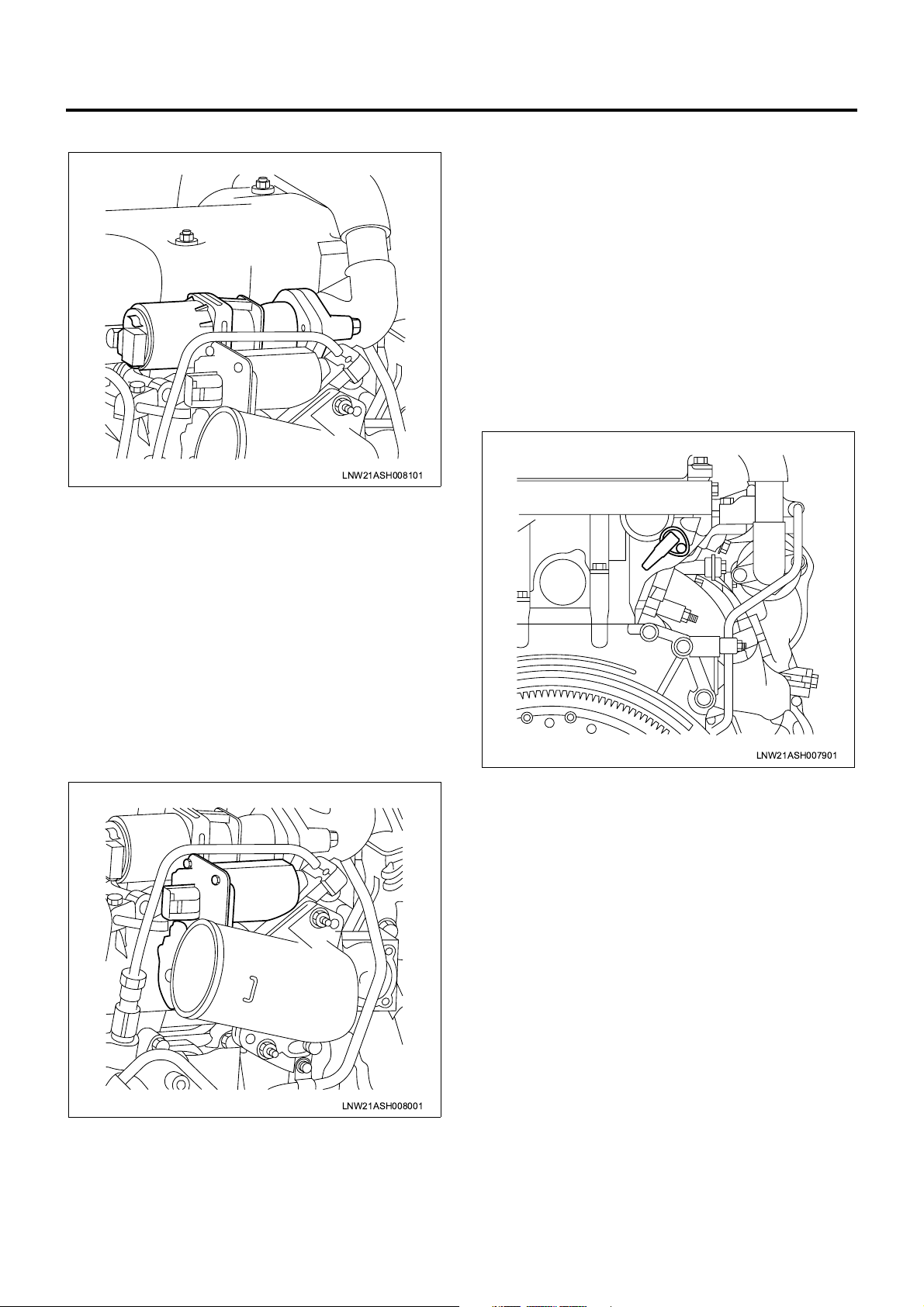
EGR Valve and EGR Valve Position Sensor
LNW21ASH008101
The EGR valve is installe d at the top of the inlet cov er
and operated by a DC motor. The DC motor operates
the EGR valve by changing the duty. The valve is
opened when the duty is inc reased while closed when
the duty is decreased. T he ECM c alculate s the desir ed
EGR valve opening based on the vehicle running
condition and controls the DC motor accordingly.
The EGR valve po sition senso r is installed to the EGR
valve and sends the voltage signal that w ill change in
response to the EGR va lve opening to the ECM. The
ECM calculates the desired EGR valve opening from
the voltage signal and uses the result in EGR control.
The intake throttle valve is installed to the intake throttle
and operated by a DC motor. The DC motor operates
the intake throttle valv e by changing the drive voltage.
The valve is closed when the drive voltage is increased
while opened when the voltage is decreased. The ECM
calculates the intake throttle valve opening based on
the vehicle running condition and controls the DC
motor accordingly.
The ITP (intake throttle pos ition) sensor is installed to
the intake throttle valve and sends the voltage signal
that will change in response to the throttle valve
opening to the ECM. The E CM calculates the throttle
valve opening from the voltage signal and uses the
result in intake throttle control.
CMP Sensor
Intake Throttle Valve and ITP Sensor
LNW21ASH007901
The CMP (cam position) sensor is installed to each
cylinder head and, when the hol e on the camsha ft gear
passes the sensor, a CMP signal is generated. The
ECM identifies the cylinder from the CMP signal as well
as CKP signal sent from the CKP sensor and
determines the cran k angl e, and u ses t his a ngle in fue l
injection control and engine speed calculation. These
tasks are usually perform ed based on the CKP signal
but if the CKP sensor fails, the CMP signal will
substitute for the CKP signal.
LNW21ASH008001
Page 14
1A-12 Engine Control System
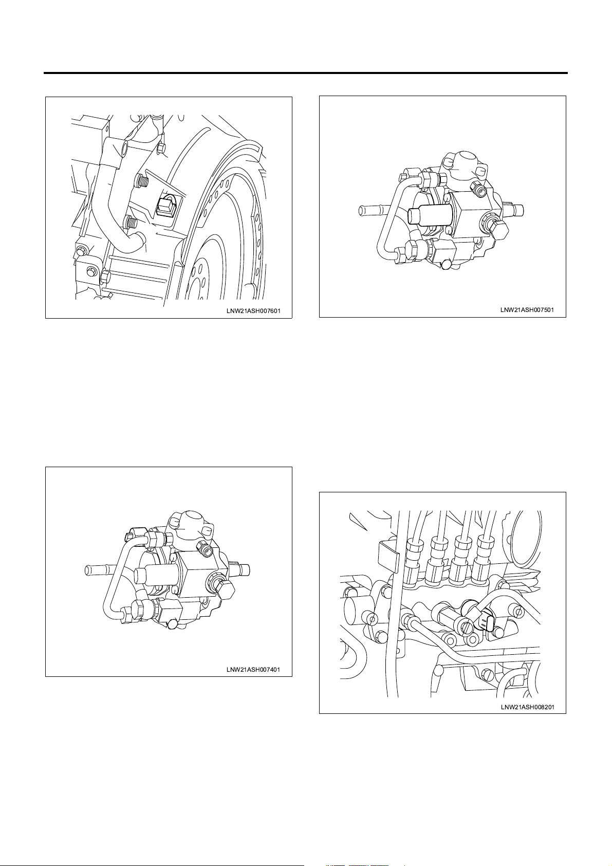
CKP Sensor
LNW21ASH007601
The CKP (crank position) sensor is installed to the
flywheel housing and, when flywheel teeth pass the
sensor, a CKP signal is generated. The ECM ident ifies
the cylinder from the CKP s ignal as well as the CMP
signal sent from the CMP sensor and determines the
crank angle, and uses this angle in fuel injection control
and engine spe ed calculati on. These t asks are usually
performed based on the CKP signal but if the CKP
sensor fails, the CMP signal will substitut e for the C KP
signal.
FT Sensor
SCV
LNW21ASH007501
The SCV (suction control valve) is installed to the
supply pump and controls the suction fuel quantity. The
SCV is fully opened in normal state and larger drive
voltage (duty) results in smaller opening. The ECM,
based on the data acquired from sensors, calculates
the desired common rai l pressure and pump flow rate
and compares the calculated desired common rail
pressure to the actual value to determine the SCV
opening. When the actual pressure is lower than the
desired value, the SCV is opened to increase the pump
flow rate. When the actual pr essure is higher than the
desired value, the SCV is closed to decre ase the flow
rate.
LNW21ASH007401
The FT (fuel temperature) sensor is installed to the
supply pump and the thermistor in the sensor alters the
resistance in res pon se to the te mpe ra tur e cha nge. The
resistance is decreased when the fuel temperature is
high while incr eased when the temper ature is low. The
ECM supplies 5 V to the FT sensor via pull-up
resistance and calculates the fuel temperature from the
change in voltage a nd uses it in supply pump control
and other control tasks. This voltage is decreased
when the resistance is smal l (the temperature is high)
while increased when the resistance is large (the
temperature is low).
Common Rail Pressure Sensor
LNW21ASH008201
The common rail pressure sensor is installed to the
supply pump, and detects the fuel pressure in the
common rail, converts the pressure into a voltage
signal, and sends the signal to the ECM. Higher
common rail pressure provides higher voltage while
lower pressure provides lower voltage. The ECM
calculates actual common rai l pressure (f uel pressure)
from the voltage signal and uses the result in fuel
injection control and other control tasks.
Page 15
Engine Control System 1A-13
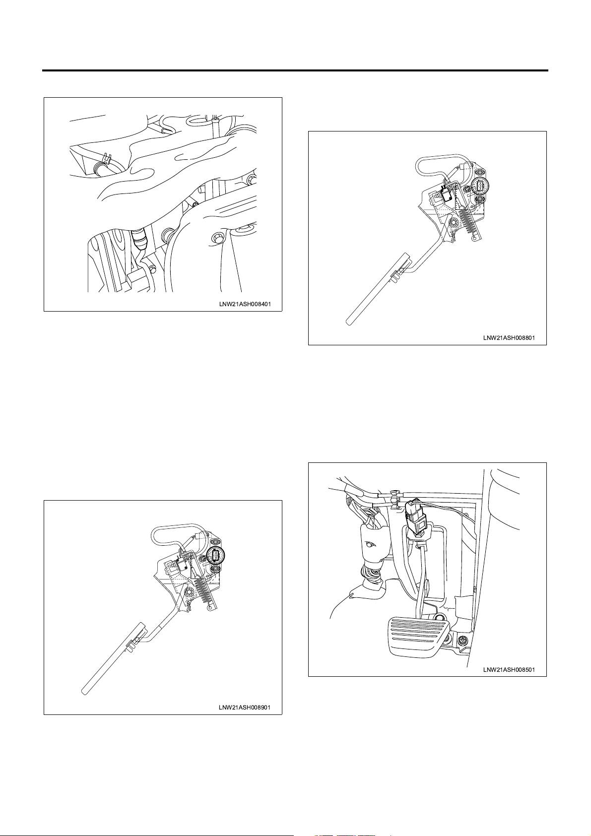
IAT Sensor
LNW21ASH008401
The IAT (intake air temperature) sens or is installed to
the intake air duct and the thermistor in the sensor
alters the resistance in response to the temperature
change. Higher intake air tem per at ure pr ov id es sm a ller
resistance while lo wer intake air temperature prov ides
larger resistance. The ECM supplies 5 V to the IAT
sensor via pull- up resistance a nd calculates the intake
air temperature from the change i n voltage and us es it
in fuel injection control and other control tasks. The
voltage is decrease d when the resistan ce is small (the
temperature is high) while increased when the
resistance is large (the temperature is low).
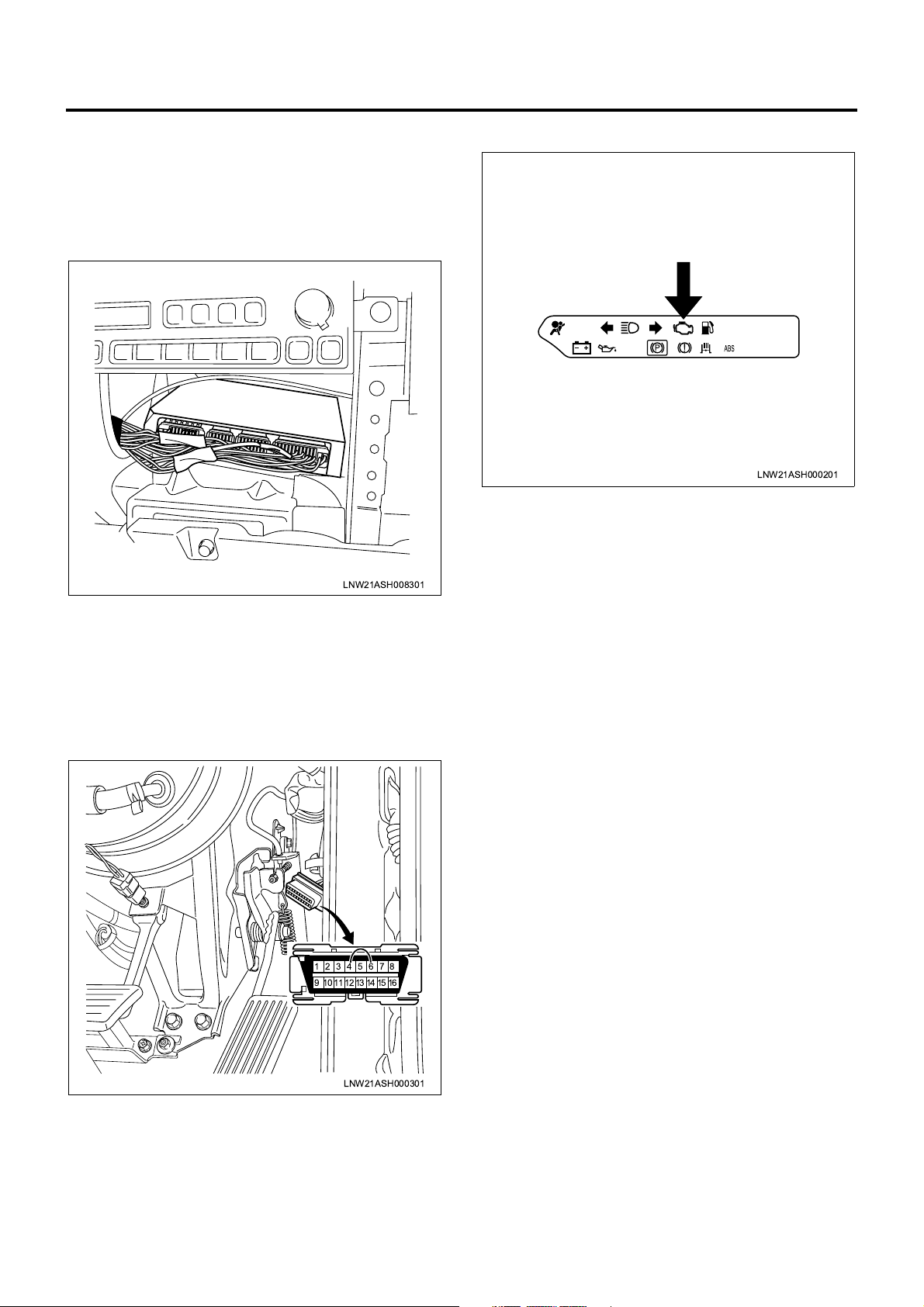
voltage signal for us e in fuel inje ction con trol and o ther
diversified control tasks.
Idle Position Switch
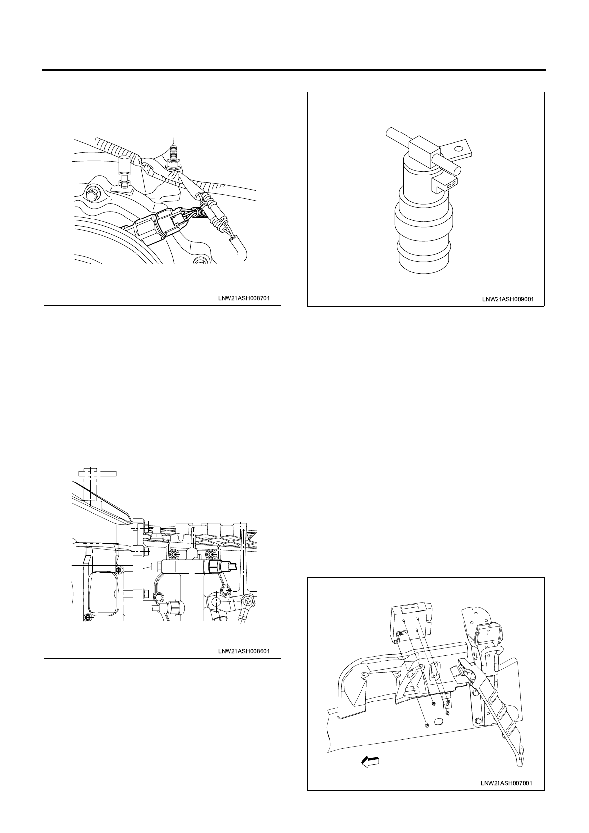
LNW21ASH008801
The idle position switch is installed to the accelerator
pedal, and is turne d off when the pedal is presse d and
turned on when the pedal is released. The ECM
receives the on/off signal fro m this idle position switch
for use in exhaust brake control, warm-up control, and
other control tasks.
Clutch Switch
AP Sensor
LNW21ASH008901
The AP (accelerato r pedal position) s ensor is installed
to the top of the accelerator pedal and supplies the
voltage signal that will change in response to
accelerator pedal angle to the ECM. The ECM
calculates the accelerator pedal position from the
LNW21ASH008501
The clutch switc h is i ns tal led to th e c lu tc h p eda l, and i s
turned on when the pedal is pressed and turned off
when the pedal is release d. The VIM receives the on/
off signal from this clutch switch for use in exhaust
brake control and other control tasks.
Page 16
1A-14 Engine Control System
VS Sensor
LNW21ASH008701
The VS (vehicle speed) sensor is installed to the
transmission. T he sensor is also equipped with a Hall
effect circuit. The magne t mounted to th e transmis sion
output shaft is rotated together with the shaft to
generate a magnetic field. This Hall effect sensor
interacts with the magnetic field and generates and
sends a signal to the VIM . The VS sens or is ener gized
via meter fu se . T he VI M us es VS s i gn al pu ls es t o j ud g e
the vehicle speed.
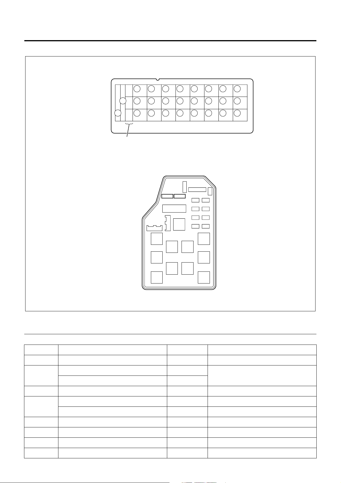
Neutral Switch
Exhaust Brake Solenoid Valve
LNW21ASH009001
The exhaust brake solenoid valve is installed to the
rear of the right front wheel frame (s ome vehicle types
have different positions), and opens and closes the
vacuum path connected to the exhaust brake valve.
When this solenoid valve is turned on, the path is
opened and the vacuum is applied to the exhaust brake
valve. When the solenoid valve is turned off, the path is
closed and the atmospheric pressure is applied and
resultantly the exhaust brake valve is released. After
the exhaust brake s witch is turned on and the vehicle
meets all the nece ssary conditions, the E CM turns on
the exhaust brake solenoid valve.
LNW21ASH008601
The neutral switch (P/N switch in case of automatic
transmission) is installed to the transmission (shift lever
in case of automatic transmission), and is turned on
when the shift lever is moved to the neutral position.
The ECM receives the on/off signal from this neutral (or
P/N) switch to control the powertrain so that the dri ver
cannot start the engine as long as the shif t lever is not
in the neutral (or parking) position.
Atmospheric Pressure Sensor
The atmospheric pressure sensor is installed inside the
VIM and converts the atmospheric pressure into a
voltage signal. The VIM calculates the atmospheric
pressure from the voltage signal and sends the result to
the ECM. The ECM u ses this atmosp heric pressure to
calibrate the fuel injection quantity (altitude
compensation).
ECM
LNW21ASH007001
Page 17
Engine Control System 1A-15
The ECM is installed in the inner par t of the engine lef t
side cover. The ECM uses sign als s en t fr om di ve rsified
sensors to control tho se sys tems direc tly rela ted to the
engine, for example, fuel injection control, intake
throttle control, EGR control, and QWS control.
VIM
LNW21ASH008301
The VIM is installed inside the center console in the
cab, and transmits signals sent from diversified
switches and sensors and drives powertrain actuators
such as exhaust brake, relays, and warning lamps
according to the commands from the ECM.
CHECK ENGINE Lamp (MIL)
LNW21ASH000201
The CHECK ENGINE lamp (MIL) is built in the meter
panel and informs th e driver of faulty status of e ngine
or associated syst ems. When the ECM detec ts a fault
by means of its diagnostic function, this CHECK
ENGINE lamp is turned on. A fter the diagnostic sw itch
is turned on (DLC pins are shorted), the CHECK
ENGINE lamp blinks to inform the mechanic of
detection of DTC.
DLC
87654321
161514131211109
LNW21ASH000301
DLC (data link connec tor) is installed to the da sh side
pane of the driver ’s seat and acts as a communicat ion
interface between external diagnostic tool and onboard controllers. The DLC can also function as a
diagnostic switch and when DLC pins are shorted , this
diagnostic switch is turned on.
Page 18
1A-16 Engine Control System
Fuse Layout
[Fuse Box Label, In Glove Box]
22
19
16
13
10
1
4
7
25
23
26
[Fuse Box, Front Left of Radiator]
24
1
20
21
17
18
27 28
14
15
11
12
2
5
8
6
9
3
LNW21ALF000401-X
Legend
1. Spare fuse
No. Indication on label Capacity Devices connected
1 CONTROLLER 10A Control unit
HAZARD,HORN (12V) 15A
2
Hazard warning flashing lamp, horn
HAZARD,HORN (24V) 10A
3—10A—
AIR CON (12V) 10A Air conditioner
4
HEATER,AIR CON (24V) 15A Heater, air conditioner
5 FUEL, SEAT HEATER (24V) 10A Fuel, seat heater
6 ABS, HAB, RETARDER (24V) 15A ABS, HAB, retarder
7 ROOM LAMP 15A Room lamp
8 STOP LAMP 10A Stop lamp
Page 19

Engine Control System 1A-17
No. Indication on label Capacity Devices connected
9 POWER WINDOW (24V) 20A Power window
10
11 FOG.CORNER 10A Fog lamp, cornering lamp
12 ELEC.PTO (24V) 10A PTO switch (electric PTO)
13 WIPER,WASHER 15A Wiper, window washer
14 TURN 10A Turn signal lamp
15
16
17 MIRROR 10A Electrically operated mirror
18 CIGAR,AUDIO 10A Cigarette lighter, audio
19
20
21 AIR BAG 10A SRS airbag
TAIL.ILLUMI (12V) 15A
Tail lamp
TAIL.ILUMI (24V) 10A
GENERATOR (12V) 15A Generator
ELEC.PTO (24V) 20A PTO solenoid valve (electric PTO)
MIRROR HEAT (12V) 10A Heated side mirror
ENG.CONT (24V) 15A ECM
METER (12V) 10A
Meter
METER (24V) 15A
ENGINE STOP (12V) 10A Engine stop
HSA (24V) 10A HSA
22 STARTER 10A Starter
23 H/LAMP RH 10A Headlamp, RH
24 H/LAMP LH 10A Headlamp, LH
25
26 POWER WINDOW (12V) 30A Power window
External Fuse Box
No. Indication on label Capacity Devices connec te d
27 MARKER LAMP 10A Marker lamp
28 COND FAN 10A Condenser fan
HEATER (12V) 30A Heater
ENG CONTROLLER (24V) 30A ECM (except for turbocharged vehicles)
Page 20

1A-18 Engine Control System
Relay Layout
Relay Box No.2
Bracket
Spare Power Circuit
18
16
15
14
13
Relay Box No.1
8
7
6
5
Upper
12
11
10
9
20
19
Cooler Relay
1
4
3
2
No. Legend
12 V: On relay
1
24 V: C harge relay
2 Horn relay
Fuse &
Relay Box
RightFront
17
LNW21ALF006101-X
12 V: ABS, VSV, FICD, EXH brake, valve (12 V)
3
24 V: Headlamp relay
4Tail relay
12 V: Headlamp relay
5
24 V: 4WD relay
6 Dimmer relay
7 Power window relay
8 Fog lamp relay
Page 21

No. Legend
9 Cornering lamp relay
10 Air conditioner thermo relay
12 V: C harge relay
11
24 V: Key on relay
12 Heater & air conditioner relay
24 V: PTO cut relay for electric PTO in fire engine (MT)
24 V: PTO solenoid relay for electric PTO (AT)
12 V: Exhaust brake cut relay (MT)
13
24 V: Idle on relay for fire engine (AT)
24 V: Idle stop, wiper relay (with CFS (clutch free system))
24 V: PTO solenoid relay for electric PTO (MT)
24 V: PTO buzzer relay for electric PTO (AT)
12 V: OD off relay (AT)
14
24 V: Idle keep relay for fire engine (AT)
Engine Control System 1A-19
24 V: Idle stop, radio relay (with CFS)
24 V: PTO main relay for electric PTO (MT)
24 V: Garbage relay for garbage collector (AT)
15
24 V: Indicator lamp relay for fire engine (AT)
24 V: Idle stop, engine control module relay (with CFS)
4WD relay
16
24 V: Idle stop, mirror relay (with CFS)
24 V: Full automatic air conditioner, high relay
17
24 V: Automatic air conditioner, high relay
24 V: Shift lock relay for fire engine (AT)
24 V: Shift relay for fire engine (AT)
18
24 V: PTO main relay for electric PTO (MT)
19 24 V: PTO solenoid relay for electric PTO (MT)
20 24 V: PTO cut relay for electric PTO (MT)
Page 22
1A-20 Engine Control System
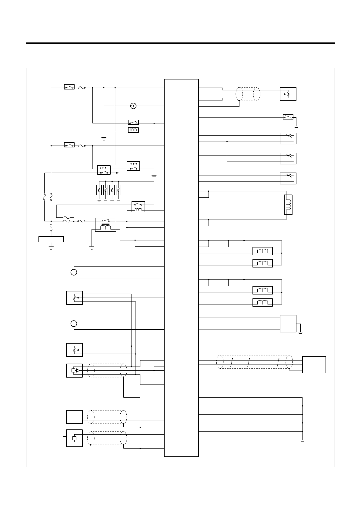
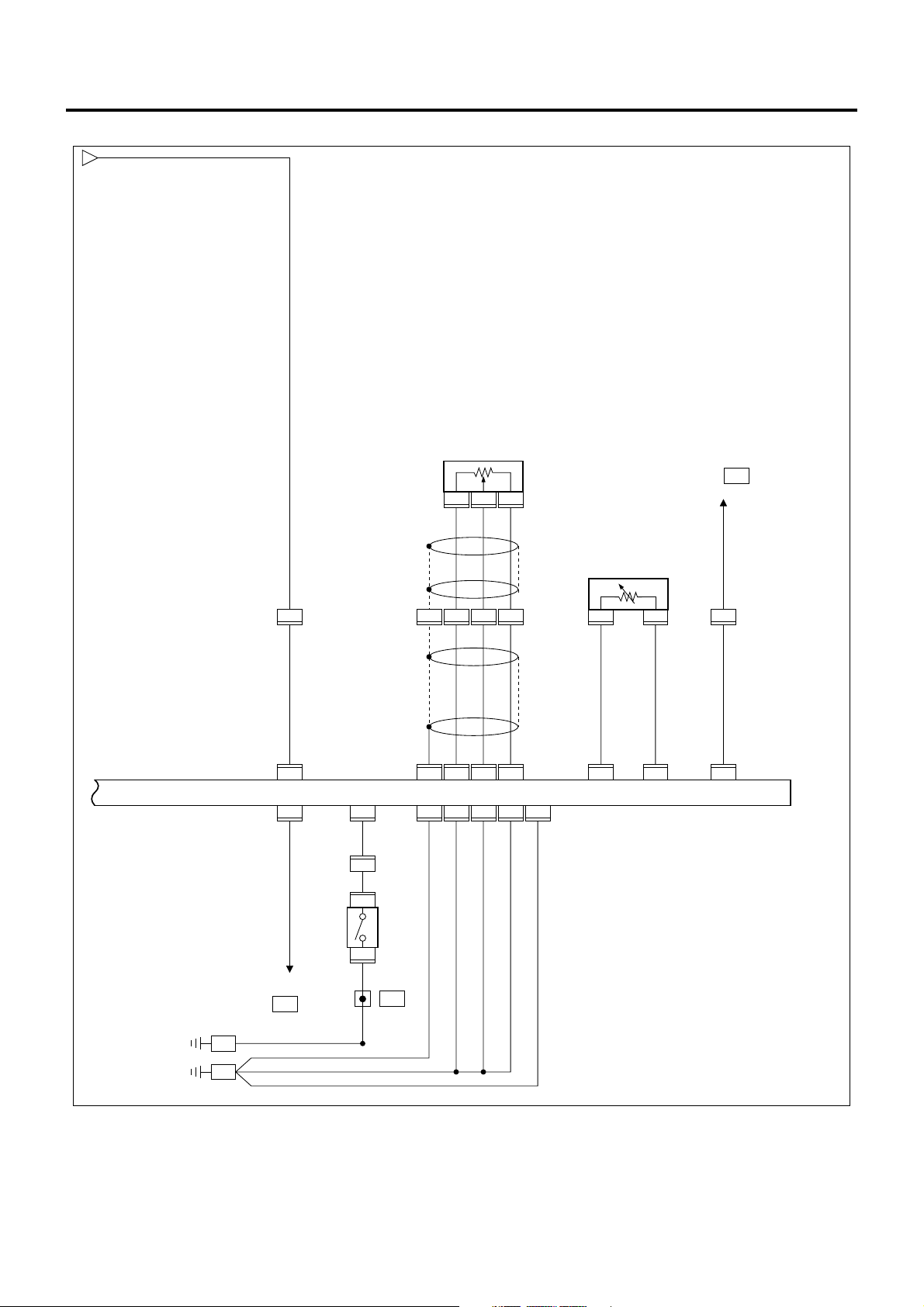
Circuit Diagram
ECM Circuit Diagram
Starter
Switch (ON)
SBF
60A
100A
SBF
Battery
Intake
Throttle
DC Motor
ITP
Sensor
EGR
DC Motor
Starter
Switch (ST)
SBF
50A
SBF
60A
SBF
50A
M+
M-
M+
M-
#19
15A
#22
10A
SBF
30A
M
M
Starter
Relay
Glow
Plug
Main Relay
CHECK ENGINE
A/C Condenser
A/C Magnetic
Cut Relay
To Starter
Lamp
Clutch
Starter
Glow
Relay
0.75B/O 0.5L
0.5Y/B
0.75W/R
0.5B/W
0.5B/R
0.5W/G
1.25W/R
1.25W/R
1.25W/R
0.5L/Y
0.5L/Y
0.75W/G
0.75R
0.5G/Y
0.75W/B
0.75L/Y
109 90
99
13
113
102
98
114
115
116
117
118
16
ECM
35
69
59
58
84
94
108
110
49
46
48
91
83
80
81
74
75
43
42
24
23
88
112
0.5L/W
0.5L/R
0.5B/Y
0.5W/L
0.5R/B
0.5G/W
0.5R/G
0.85L/B
0.85O
0.75W/R
0.75W/R
0.75L
0.75L
1.25W
1
2
1.25L/W
0.75G/W
0.75B
1.25R
4
5
1.25L/R
0.75W/Y
0.75L
0.5SB
0.5GR/W
Idle Position Switch
Scan Tool Communication
Diagnostic Switch
AP
Sensor
ECT
Sensor
FT
Sensor
IAT
Sensor
SCV
Cylinder 1 Injector
Cylinder 4 Injector
Cylinder 3 Injector
Cylinder 2 Injector
DLC
EGR Valve
Position
Sensor
Common Rail
Pressure
Sensor
CKP
Sensor
CMP
Sensor
0.5Y
0.5W
0.5G
0.5G
0.5R
0.5W/R
0.5W/L
0.5L/R
0.5L/W
0.5B
68
0.5R
63
67
66
64
25
6
8
27
26
89
97
87
95
119
120
121
0.5W
0.5B
0.85B
1.25B
1.25B
1.25B
VIM
0.5B
LNW21AXF002601-X
Page 23

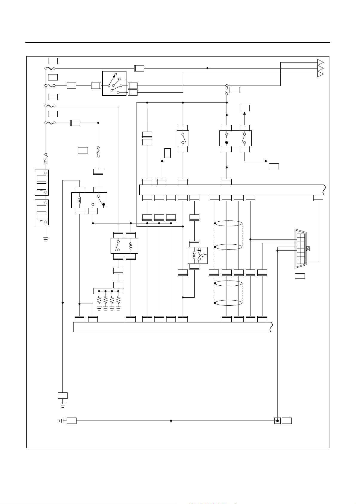
VIM Circuit Diagram
Engine Control System 1A-21
SBF
50A
SBF
100A
Battery
Starter SW (ON)
Starter SW (ST)
SBF
SBF
30A
50A
#19
15A
Exhaust
Brake Lamp
Exhaust
Brake Solenoid
PTO Lamp
PTO SW
#22
Main Relay
10A
Glow Lamp
ECO Relay
Clutch SW
Exhaust Brake SW
Warm Up SW
M/T : N A/T : P or N
Freezer SW
CFS Non Vehicle
PTO ECU
CFS Vehicle
CFS
0.85B/O
0.3BR/W
0.5LG/B
0.5V/W
0.5B/W
1.25W/R
1.25W/R
1.25W/R
0.3O/L
0.5G/Y
0.5W/L
0.5LG/R
0.5BR/R
0.5B/G
0.5L/B
36
0.5B/R
4
2
7
46
38
75
76
16
0.3B/G
53
0.3LG/B
56
18
59
17
15
19
57
54
0.5BR
0.5B/R
0.3B/L
0.5G/Y
0.5G
0.5L/R
0.5LG
A/T ECU
Tachometer
ABS/ASR
ECU
Sound Alarm
(Simplified ISS)
CFS ECU
42
3
49
50
12
44
47
V I M
27
26
48
0.5W
0.5R
0.5B
0.5G/W
Lamp
Fail Relay
ECM
Brake SW
+B
Stop
Lamp Relay
Other ECU
PTO
Accelerator
Sensor
Idle Up
Volume
VS Sensor
0.5Y/BR
0.5Y/G
0.5R/B
0.5Y
0.5Y/G
9
0.5SB
24
34
31
71
30
14
0.5B
73
0.85B
60
0.85B
39
0.85B
52
0.85B
66
Diagnostic SW
DLC
Scan Tool Communication
LNW21AXF002301-X
Page 24
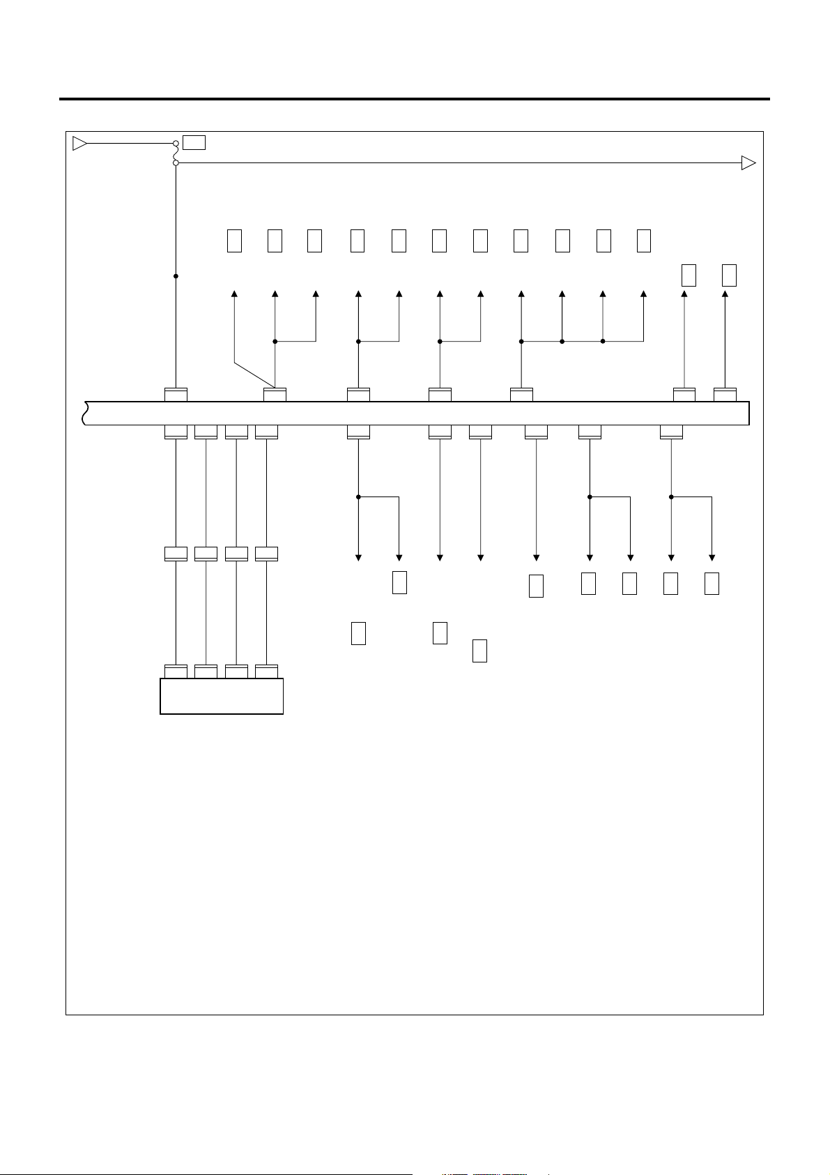
1A-22 Engine Control System
ECM/VIM Circuit Diagram (1/5)
MAIN
KEY
GLOW
ECM
2L
+
P-1
P-2
+
P-3
P-4
Frame
SBF-1 80A/100A
SBF-2 50A
3 W/L
SBF-3 60A
SBF-5
50A
3 W/G 3 W/G
0.5
B
B-67
B-67
1
H-6
3
4
3B/Y
3B/W
5 W/B 5 W/B 3 W/B
OFF
ACC
H-7
B-67
21
3 W/L
ON
B
ST
Starter Switch
2
H-7
F-25 30A
ENG.CONT
X-18
Main Relay
X-182X-18
0.5
L/Y
0.5
L/Y
117
J-191
3
5
W/R
Glow Plug
0.5
L/Y
3
J-191
W/G
W/G
W/G
3
2
2
118
H-4
X-18
0.3
B/O
1
B-355
B-354
1
Air Bleed Connector
0.3
J-191
0.85
B/O
98
P
10 49
B-352
B-349
38
1.25
W/R
H-4
Glow Relay
1.25
W/R
114
J-191
0.5
LG/L
B-352
B-34975B-349
1.25
W/R
8
H-4 H-4
1.25
W/R
J-191
9
3
B/L
1
3
0.5
B/L
W/R
2
X-224X-22
X-225X-22
3
3
B/G
2
H-105
3
0.5
B/G
W/G
E-3
B/O
B-258 (2)
CFS Control Unit
W/L
76
1.25
0.85
W/R
B/O
67
0.85
B/O
1.25
0.75
W/R
B/O
0.75
B/O
115
116
J-191
0.5
0.5
B-352
B-349
J-191
B-89
B-89
H-5
109
1
2
49
36
0.5
LG/B
0.5
LG/B
8
0.5
B/O
Clutch Switch
B-352
2
19
H-4
2
J-31
J-31
1
B-350
0.5
B
Exhaust Brake
Solenoid Valve
ECM
F-16 15A
ENG. CONT
PTO Cut Relay
B/O
B/O
0.5
0.5
B-216 (4)
0.5
R/Y
21
B-89 B-89
Clutch PTO Switch
B-894B-89
3
0.5
0.5
G/O
B/O
0.5
B/O
49
B-352
VIM
B-350
B-350
B-350
26
65
0.5R0.5
W
4
H-413H-412H-48H-81H-8
0.5R0.5
W
97
J-19189J-19188J-191
24
27
0.5
LB
0.5
GR/W
J-191
PTO Solenoid M/T Relay
B-64 (3)
0.5 LB
0.5 GR/W
0.5 B
0.5 B
Diagnostic Connector
0.85
B
112
12345678
B-79
A
C
B
B-352
9
10111213141516
0.5 L
9
Left Side Frame
Right Frame (Front)
3
B
J-9
(Center)
B-274
3 B 1.25 B
6
8
B-274
Joint Connector
LNW21AXF002701-X
Page 25

Engine Control System 1A-23
ECM/VIM Circuit Diagram (2/5)
Charge Relay
0.3
B
0.5
LG/R
B-35166B-349
B-352
39
3B/Y
X-1
Idling Stop &
Warm Up Switch
(10A)Fuse
F-10
52
(4)
B-172
Joint
Connector
0.3
B/R
0.5
B
35
B-31 B-31
B-312B-31
6
0.5
LG/R
12
TAIL,ILLUMI
B-352
B-35073B-349
60
3B/W
67
1.25B
8
F-10
GND
B-274
Warm Up Switch
(10A)Fuse
VIM
B-349
71
F-19
Meter
1
2
Joint
Connector
31
H-5
0.85
B/Y
0.5
B/Y
1
J-50
J-50
2
0.5
B/G
14
H-4
0.5
B/G
44
B-352
SIG SIG5VGND
B-34934B-349
31
15A
B-172
Neutral
Switch
(M/T)
TCM
B-47
(JATCO)
0.3
W/L
0.3
W/L
44
B-352
12
Inhibitor Switch
(AISIN)
NP
J-69
J-69
5
W/L
W/L
0.5
0.5
0.5
W/R
20
H-4622H-46
0.5
W/R
7
X-33
X-33
6
8
Diode
X-33
9
0.5
B/G
44
B-352
B-349
30
A
3W/B
C
B D
12
X-12 X-12
X-12
3
5
B/R
FUEL, SEAT HEATER
0.5
B/R
0.5
5
B/R
B-69
B-69
2
0.5
LG/R
50
B-352
X-12
10A
F-5
Switch
Exhaust Brake
0.5W/R
Heater & A/C
Relay
4
0.5B 0.5B
0.5
BR
62
B-319 B-319
B-3195B-319
3
12
TAIL,ILLUMI
B-352
B-352
47
0.85
0.5
L/B
0.5
0.85
B
B
B
B
B
0.5
0.85
0.85
0.5
0.5Y0.5
Y/BR
B-2821B-3253B-282
R/B
1
PTO Accelerator Sensor
0.5
0.5
Y/BR
Y/G
1
B-2812B-2813B-281
Idle Control Switch
0.5
R/B
Y/BR
55
0.5
Y/BR
1
J-1662J-166
0.5Y0.5
H-4H-8
0.5Y0.5
R/B
73
H-8 H-8
0.85
R/B
J-166
L/B
3
J-7
1
PTO Accelerator Sensor
Compressor
Left Frame (Front)
B-346
LNW21AXF002801-X
Page 26
1A-24 Engine Control System
ECM/VIM Circuit Diagram (3/5)
D
3B/W
0.5
B/W
F-22
STARTER
10A
0.5B/W
E
B-259 6
CFS C/U
0.5
B/W
B-352
B-351
0.3
B/L
H-8
0.3
B/L
J-1778J-17719J-17720J-177
0.5
L/R
46
B-351
B-35117B-351
15
19
12
7
B/R
0.5
LG/W
0.5
H-8
G/Y
11
G/Y
57
0.5
18
H-817H-8
0.5
EHCU
G/B
0.3
B-351
B-229 5 (AISIN)
TCM
18
B-47 20 (JATCO)
TCM
B/G
0.3
B-351
B-229 23 (AISIN)
TCM
53
B-47 13 (JATCO)
TCM
0.3
LG/B
B-351
B-230 7 (AISIN)
TCM
56
B-47 8 (JATCO)
TCM
B-52 8 (Tachometer)
Meter
0.5
LG
59
B-351
0.3
LG
B-229 1 (AISIN)
TCM
0.5
LG
B-48 4 (JATCO)
TCM
B-259 1
CFS
X-15 3
B-147 3 (Idling Stop)
Parking Warning Unit
Idling Stop ECM Relay
0.5
LG
0.5
0.5
G
G/Y
54
B-3513B-352
VIM
B-351
14
0.5
BR
0.5
BR
Y/G
0.5
B-52 17 Speed Meter
Meter
B-35242B-352
0.3
BR/W
J-32 3
Speed Sensor
4
0.3
O/L
B-51 6 EXH Brake W/L
B-52 15 Glow Indicator Lamp
Meter
0.5
W/O
B-352
11
B-259 19
CFS C/U
B-352
48
0.5
G/W
X-3 2
Stop Lamp Relay
B-352
7
0.5
V/W
B-84 2
B-66 2
PTO Switch (M/T)
Stop Lamp Switch
B-77 1
Dump Control Switch
Meter
LNW21AXF002901-X
Page 27
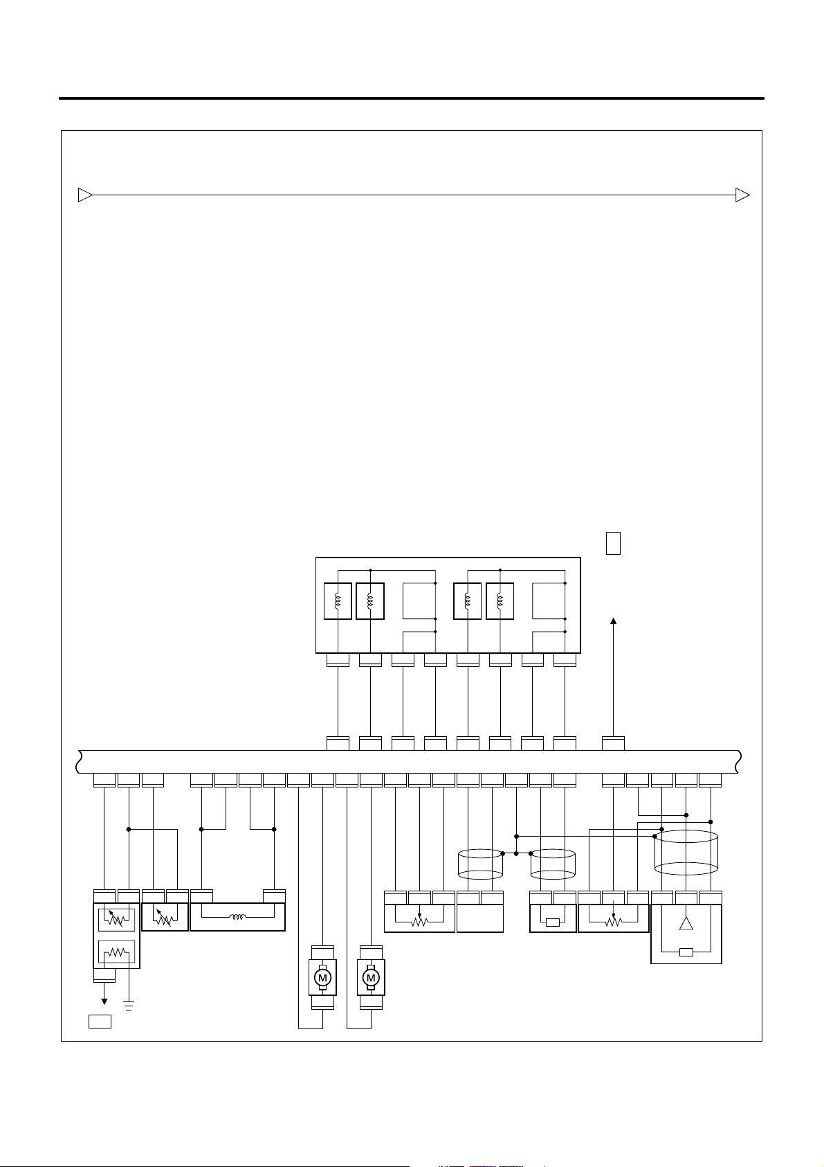
ECM/VIM Circuit Diagram (4/5)
Engine Control System 1A-25
E F
0.5B/W
Injector
E-5 (1)
E- 11154E- 11119E- 111
22
0.5
0.5
0.5
R/B
0.5
Y/B
R/G
G/W
0.5
G/W
1
E-902E-902E-931E-931E-116
E-90
3
0.5
G/W
Fuel
Temperature
(FT) Sensor
Meter
B-52 (5)
No.2 No.3 No.4 No.1
E-115
6
0.75
L
E- 11133E- 11134E- 11117E- 11112E- 11129E- 11146E- 11145E- 111
0.75
W/R
0.75
W/R
16
0.75
0.75
L
W/R
Suction Control
Valve (SCV)
0.75L0.75
0.75
L
E-116
0.75
0.75
W/G
0.75
E-114
E-114
R
L/Y
0.75
L/Y
3
Intake Throttle DC Motor
6
R
0.75
R
2
E-1153E-1158E-1155E-1151E-1154E-115
0.75
W/Y
E-115
E- 1114E- 111
2
7
0.75
0.75
1.25
1.25
L/R
R
2426
G/W
B
ECM
E- 1111E- 11156E- 11136E- 11137E- 11152E- 11118E- 11135E- 111
0.75
W/B
0.75
E-94
E-94
L/Y
G/Y
W
4
E-1142E-1141E-1141E-982E-98
Intake Throttle
4
Position (ITP)
Sensor
EGR DC Motor
6
39
0.5
0.5
0.5
R
0.5
0.5
W/L
W/R
Crank Position
(CKP) Sensor
Magnetic Clutch
3013793215
0.5
W
0.75
W/R
13
E- 111
E- 111
2
0.5
Y
EGR Position
Sensor
E- 11138E- 111
21
0.5G0.5
0.5
R
W
1.25
1.25
L/W
W
E- 111E- 111E- 111E- 111E- 111E- 111
0.5
0.5
0.5
B
L/W
L/R
3
E-1122E-1121E-943E-942E-943E-1132E-1131E-113
Cam Position
(CMP) Sensor
E- 111
E- 111
455
0.5
G
0.5G0.5
R
Common Rail
Pressure Sensor
LNW21AXF003301-X
Page 28
1A-26 Engine Control System
ECM/VIM Circuit Diagram (5/5)
F
0.5
B/W
Accelerator Sensor
B-2802B-2801B-280
3
Meter
B-51 5
(CHECK ENGINE Lamp)
Right Frame (Front)
B-274
0.5
L
30
H-5
0.5
B/W
113
J-191 J-191
ECM
J-191
102
0.5
B/R
Starter
Cut Relay
X-26
J-191
110
0.5
W/L
2
H-8
0.5
W/L
1
B-75
Accelerator
Pedal
Switch
B-75
2
0.5
B
10
1.25
B
B-172
6
Joint
Connector
3
3B
10
H-4
H-43H-42H-4
0.5
L
0.5
B/Y
108
J-19190J-191
5V GNDSIG 5V SIG
J-191
J-191
95
0.75
1.25
B
B
121
L/R
L/W
1
0.5
0.5
L/R
L/W
94
84
J-191
J-191
J-191
J-191
J-191
120
119
87
0.5
1.25
1.25
B
B
B
0.85
J-190
O
J-191
IAT Sensor
2
83
J-190
1
0.5
L/B
91 99
J-191
0.5
0.5
0.5
Y/B
4
H-8
0.5
Y/B
Left Frame (Center)
J-9
LNW21AXF003101-X
Page 29

Component Layout
Engine Control System 1A-27
56
55
54
53
52
51
50
49
48
47
41,42,43,44,45,46
40
57
39
32
31
1
2,3
4
5
6
7
8
9
25
24
10
12
11
13
14
15
16
17
Legend
33,34,35,36,37,38
26,27,28,29,30
23
22
21
20
1 B-172 Joint connector
2 X-12 Heater and air conditioner relay (825/151)
3 X-33 Diode (810/002)
4 B-349, 350, 351,
VIM (826/646)
352
5 J-31 Exhaust brake magnetic valve (156/086)
6 J-50 Neutral switch (230/171)
7 J-166 PTO accelerator sensor (101/867)
8 P-5 Frame ground
9 P-1 & P-2 Battery
10 P-3 & P-4 Battery (24 V)
11 E -3 Glow plug (011/010)
12 E-115 Injector (040/031)
13 E-113 Common rail pressure sensor (040/21 1)
14 E-94 EGR vacuum sensor (057/667)
14 E-94 EGR valve (057/001)
15 E-114 Intake throttle position sensor (025/373)
18
19
LNW21ALF006301
Page 30

1A-28 Engine Control System
15 E-114 Intake throttle motor (025/373)
16 E-98 Crank position sensor (826/648)
17 E-112 Cam position sensor (040/001)
18 E-96 Timing control valve (040/001)
18 E-111 ECM (060/613)
19 H-105 Intermediate connector
20 J-190 IAT sensor (060/820)
21 E-116 Su ction co ntr ol valv e (040/001)
22 E-93 Fuel temperature sensor (040/205)
23 E-90 Engine coolant temperature sensor (060/129)
24 J-69 Inhibitor switch (249/001)
25 J-9 Left frame (center) ground
26 F-5 Fuel seat heater fuse (810/005)
27 F-16 ENG.CONT fuse (810/005)
28 F-19 Meter fuse (810/005)
29 F-22 Starter fuse (810/005)
30 F-25 Engine controller (main) fuse (810/005)
31 B-346 Left frame (front) fuse
32 J-7 Compressor connector
33 SBF-1 Main slow blow fuse (810/174)
34 SBF-2 Key switch slow blow fuse (810/174)
35 SBF-3 Glow slow blow fuse (810/174)
36 SBF-5 ECM slow blow fuse (810/174)
37 X-18 Main relay (828/531)
38 X-22 Glow relay (060/046)
39 J-177 EHCU (350/089)
40 B-274 Right frame (front) ground
41 H-4 Intermediate connector
42 H-5 Intermediate connector
43 H-7 Intermediate connector
44 H-8 Intermediate connector
45 H-6 Intermediate connector
46 H-46 Intermediate connector
47 B-354 Air ve nt conn ec tor
47 B-355 Air ve nt conn ec tor
48 B-89 Clutch switch (825/021)
49 B-67 Starter switch (431/103)
50 B-69 Exhaust brake switch (825/001)
51 B-79 Diagnostic connecto r (DL C)
52 B-75 Accelerator switch (101/079)
53 B-280 Accelerator position sensor (101/243)
54 B-282 & B-325 PTO accelerator connector
55 B-281 Idle up position switch (101/262)
56 B-51 & 52 Meter warning (821/001)
57 B-31 Warm-up switch (825/423)
Page 31

Connector List
Engine Control System 1A-29
No. Connector face
B-31
B-51
B-52
1
9 10111213 14 151617181920
1 23
456
123
45
No. Connector face
87654321
B-79
006-024
5678234
020-024
005-025
B-89
B-172
1
1221331441551661771881992010211122
161514131211109
016-033
1
2
002-011
022-005
B-67
B-67
B-69
B-69
241
3
1 2
34
8
1526374
B-274
004-035
B-280
004-015
1523674
B-281
008-028
8
008-021
B-282
123
123
123
000-012
003-098
003-064
003-015
B-75
12
002-022
B-325
2 1
002-015
Page 32

1A-30 Engine Control System
No. Connector face
B-346
38 37 28
B-349
367435733472337132703169306829
76 75 66
2765266425632462236122
B-350
B-351
215920581957185617551654155314
No. Connector face
E-90
000-037
67
022-025
60
012-054
52
016-067
E-93
E-94
E-98
12
3
003-095
12
002-208
1423
5
005-034
1 2
002-178
B-352
B-354
B-355
E-3
13 12 3
1110987654
51 50 41240139
49 48 47 46 45 44 43 42
1
1
1
026-013
001-003
001-034
001-029
E-111
E-112
E-113
E-114
17
18
19
20
21
22
23
9
10
6
7
44
45
63
64
11
8
46
65
12
13
14
15
16
36 37 38 39 40 41 42 4328 29 3025 26 27 31 32 33 34 35
55
56
57
47
48
49
50
51
52
53
66
67
68
69
54
70
71
72
73
58
74
75
76
77
24
54
59
60
78
79
3
61
62
21
80
81
081-001
123
003-097
123
003-111
14253
6
006-084
Page 33

Engine Control System 1A-31
No. Connector face
E-115
E-116
H-4
H-4
1526374
1 2
9876
2019 18 17 1651415413312211110
12345
1011 12 13 1415
6789
1718 19 20
16
No. Connector face
8
008-046
J-31
J-50
002-178
J-177
020-002
J-177
020-001
12
12 11 10 9 8 7 6 5 4 3
22 21 20 19 18 17 16 15 14 13
34 33 32 31 30 29 28 27 26 25
12
12
3456789101112
13 1415 16 17 18 19 20 21 22
252423 26 27 28 29 30 31 32 33 34
21
24
002-008
002-210
034-001
23
034-002
H-46
H-46
H-105
J-9
123 456
7 8 9 10 11 12 13 14
15 16 17 18 19 20 21 22
1
2
34 56
113
112
111
110
109
108
107
123456
78912 11 101314
15161720 19 182122
022-013
J-191
121 120 1 19
118 117
116 115 114
105
97
89
104
96
88
103
95
87
102
94
86
101
93
85
100
92
84
99
91
83
106
98
90
82
040-004
P-1
022-012
(24V)
000-028
P-2
006-005
(24V)
000-029
P-3
000-012
(24V)
000-029
Page 34

1A-32 Engine Control System
No. Connector face
P-4
(24V)
P-5
(24V)
1
24
X-12
X-18
3
5
1
2
345
000-028
000-021
005-012
005-023
H-5
H-6
123
789
13 14 15
19 20 21
25 26 27
31 32 33
34 35 36 37
1
456
10 11 12
16 17 18
22 23 24
28 29 30
38 39 40
2
H - 6
654
12 11 10
18 17 16
24 23 22
30 29 28
40 39 38
2
34353637
LNW21ASH010801
1
321
987
15 14 13
21 20 19
27 26 25
33 32 31
X-33
X-22
123
78910 11412513614
1
23
4
5
014-003
005-013
12
1234
5678
910111213
14 1516 17 18
H - 7
H - 8
21
4321
8765
13 1211 10 9
18 1716 15 14
LNW21ASH010901
Page 35

H-7 H-8
Engine Control System 1A-33
ECM Pinouts
1
2
12
1234
5678
910111213
14 1516 17 18
H - 6
H - 7
H - 8
2
1
21
4321
8765
13 1211 10 9
18 1716 15 14
LNW21ASH010901
123
789
13 14 15
19 20 21
25 26 27
31 32 33
34 35 36 37
456
10 11 12
16 17 18
22 23 24
28 29 30
38 39 40
654
12 11 10
18 17 16
24 23 22
30 29 28
40 39 38
321
987
15 14 13
21 20 19
27 26 25
33 32 31
34353637
LNW21ASH010801
LNW21ALF004501
Page 36

1A-34 Engine Control System
45
3
12
2423222120191817161514131211109876
43 42 41 40 39 38 37 36 35 34 33 32 31 30 29 28 27 26 25
62 61 60 59 58 57 56 55 54 53 52 51 50 49 48 47 46 45 44
81 80 79 78 77 76 75 74 73 72 71 70 69 68 67 66 65 64 63
106107108109110111 112113
98 99
100101102103104105
90 91 92 93 94 95 96 97
82 83 84 85 86 87 88 89
119 120
117
114 115
121
118
116
LNW21ASF002001
81-Way Connector (Engine side)
Pin No. Connected to Pin No. Connected to
1 Inj ec tors #1 and #3 42 Injector #3 (cylinder 4)
2 Inj ec tors #1 and #3 43 Injector #1 (cylinder 1)
3— 44 —
4 Inj ec tors #2 and #4 45 —
5 Injectors #2 and #4 46 Sensor ground (ECT, FT)
6 CKP sensor (–) 47 —
7 — 48 FT sensor signal
8 CMP sensor signal 49 ECT sensor signal
9— 50 —
10 — 51 —
11 — 52 —
12 — 53 —
13 Air conditioner 54 —
14 — 55 —
15 — 56 —
16 Intake throttle DC motor (+) 57 —
17 — 58 EGR DC motor (–)
18 — 59 EGR DC motor (+)
19 — 60 —
20 — 61 —
21 — 62 —
22 — 63 5 V sensor power (ITP, common rail
pressure, EGR)
23 Injector #4 (cylinder 2) 64 5 V sensor ground 1 (ITP)
24 Injector #2 (cylinder 3) 65 —
Page 37

Engine Control System 1A-35
Pin No. Connected to Pin No. Connected to
25 CKP sensor (+) 66 Common rail pressure sensor signal
26 Shield ground (CMP, CKP, common rail
pressure)
27 CMP sensor ground 68 EGR valve position sensor signal
28 — 69 ITP sensor signal
29 — 70 —
30 — 71 —
31 — 72 —
32 — 73 —
33 — 74 SCV (LO)
34 — 75 SCV (LO)
35 Intake throttle DC motor (–) 76 —
36 — 77 —
37 — 78 —
38 — 79 —
39 — 80 SCV (HI)
40 — 81 SCV (HI)
41———
67 Common rail pressure sensor signal
40-Way Connector (Vehicle side)
Pin No. Connected to Pin No. Connected to
82 — 102 Starter cut relay
83 5 V sensor power 2 (IAT) 103 —
84 AP sensor signal 104 —
85 — 105 —
86 — 106 —
87 Casing ground 107 —
88 DLC (Tech 2 communications) 108 Shield ground (AP)
89 VIM (CAN communications) 109 Starter switch (ON)
90 5 V sensor power 2 (AP) 110 Idle position switch
91 IAT sensor signal 111 —
92 — 112 DLC (diagnostic switch)
93 — 113 Starter switch (ST)
94 5 V sensor ground 2 (AP) 114 ECM power
95 Signal ground 115 ECM power
96 — 116 ECM power
97 VIM (CAN communications) 117 Main relay
98 Glow relay 118 Main relay
Page 38

1A-36 Engine Control System
Pin No. Connected to Pin No. Connected to
99 CHECK ENGINE lamp 119 ECM power ground
100 — 120 ECM power ground
101 — 121 ECM power ground
VIM Pinouts
LNW21AMF005101
Page 39

Engine Control System 1A-37
312
45
40
414939
42 4643 474544
1312
11971086
48
50 51
14
53
52 5554
20 2115 191816 17
5956 5857
25 26246427
22
6260236361
28
29 3632 33 3430 3531
65
68 69 70 7167 746676
37 38
7372
75
LNW21ASF001901
26-Way Connector
Pin No. Connected to Pin No. Connected to
1 — 39 VIM power ground
2 Exhaust brake solenoid valve 40 —
3 ECO (power save) relay 41 —
4 Exhaust brake lamp 42 Glow lamp
5—43—
6 — 44 Neutral (P/N) switch
7PTO switch45 —
8 — 46 Starter switch (ST)
9 DLC (diagnostic switch) 47 Freezer switch
10 — 48 Stop lamp switch
11 — 49 Clutch switch
12 Warm-up (QWS) switch 50 Exhaust brake switch
13 — 51 —
16-Way Connector
Pin No. Connected to Pin No. Connected to
14 VS sensor signal 52 VIM power ground
15 ABS/ASR controller 53 AT controller
16 AT controller 54 Voice alarm unit (idle stop)
17 ABS/ASR controller 55 —
18 AT controller 56 AT controller
19 ABS/ASR controller 57 ABS/ASR controller
20 — 58 —
21 — 59 AT con tr oll er
Page 40

1A-38 Engine Control System
12-Way Connector
Pin No. Connected to Pin No. Connected to
22 — 60 S ign al gr oun d
23 — 61 —
24 DLC (Tech 2 communic atio ns) 62 —
25 — 63 —
26 ECM (CAN communications) 64 —
27 ECM (CAN communications) 65 Shield ground (CAN communications)
22-Way Connector
Pin No. Connected to Pin No. Connected to
28 — 66 VIM power ground
29 — 67 —
30 Idle up volume 68 —
31 PTO accelerator sensor signal 69 —
32 — 70 —
33 — 71 5 V sensor ground 1 (PTO, IDL UP)
34 5 V sensor power 1 (PTO, IDL UP) 72 —
35 — 73 Casing ground
36 Starter switch (ON) 74 —
37 — 75 VIM power
38 VIM power 76 VIM power
Strategy-Based Diagnostics
Strategy-Based System Diagnostics
The system diag nostic is a unifo rm approach to repai r
all electrical/electronic (E/E) systems. In the E/E
system, different from genera l vehicle problems, faults
frequently occur along the steps shown as follows.
1. Initial stage:
• A single fault occurs for a short while and,
therefore, the customer may miss it. In this
stage, the customer complaint is unclear and
the fault cannot be reprod uced. But, the ECM
may have stored the fault.
= Past fault
2. Middle stage:
• A single fault occurs for a short while but is
observed intermittent ly. It always occurs und er
certain conditions. The customer complaint
(description of fault) is clear but fault
occurrence conditions are unidentified. If you
comprehend these conditions, you can
reproduce the trouble.
= Intermittent fault (intermittent)
3. Realistic fault:
• The fault occurs certainly and the customer
complaint is realistic and clear. You can
reproduce the fault. However, there may exist
two or more causes.
= Current fault
The diagnostic flo w can always be use d to resolve an
E/E system problem and is a starting point when
repairs are necessa ry. The fo llowing steps will instr uct
the technician how to proceed with a diagnosis:
1. Verify the customer complaint:
• To verify the customer complaint, the technician
should know the normal operation of the
system.
2. Perform preliminary checks:
• Conduct a thorough visual inspection.
• Review the service history.
• Detecting unusual sounds or odors.
• Gather DTC (diagnostic trouble code)
information using Tech 2
3. Check bulletins and other service information.
4. Refer to “Symptom Diagnosis Chart” in this
manual.
Page 41

Engine Control System 1A-39
• “Sympton Diagnosi s Chart” contai n information on
a system that may not be suppored by one or more
DTCs. Sympton Diagnosis Chart verify proper
operation of the system. This will lead the
technician in an organized approach to
diagnostics.
5. Refer to related descriptions such as those for
engine mechanicals.
DTC Stored
Follow the designated DTC chart exactly to make an
effective repair.
No DTC
Select the symptom from the “Sympton Diagnosis
Chart”. Follow to the diagnostic paths or suggestions to
complete the repair. You may refer to the applicable
components/system check in the functional check.
No Matching Symptom
1. Analyze the complaint.
2. Develop a plan for diagnostics.
3. Utilize the wiring diagrams and the theory of
operation.
Call technical assistan ce for si milar ca ses wher e repair
history may be available. Combine technician
knowledge with efficient use of the available service
information.
3. Use a check sheet or other method to identify the
circuit or electrical system com pon ent .
No Trouble Foun d
This condition exists when the vehicles is found to
operate normally. The condition described by the
customer may be normal. Verify the customer
complaint against another vehicle that is operating
normally. The condition may be intermittent. Verify the
complaint under the conditions described by the
customer before releasing the vehicle.
1. Reexamine the complaint.
When the complaint cannot be successfully found
or isolated, a re-evaluation is necessary. The
complaint should be re-verified and could be
intermittent as defined in Intermitte nts, or could be
normal.
2. Repair and verify.
After isolating the cause, the repairs should be
made. Validate for proper operation and verify that
the symptom has been corrected. This may involve
road testing or other methods to verify that the
complaint has been resolved under the following
conditions:
• Conditions noted by the customer.
• If a DTC was diagnosed, verify a repair by
duplicating conditions present when the DTC
was set as noted by Tech 2 data.
Intermittents
Conditions that are not always present are call
intermittents. To resolve intermittents, perform the
following steps.
1. Observe history DTCs, DTC modes, and engine
data.
2. Evaluate the symptoms and the condition
described by the customer.
No. Item Objective Method
1 Verifying the
DTC
2 Verifying the idle
speed after
warm-up
3 Verifying Tech 2
data list
To check the DTC is not set
after the repair.
To check the idle control is
normally performed.
To provide basic checking for
engine control and
communication con di tio ns .
Verifying Vehi cle Repair
When the electronic con trol syste m has been re paired,
it is necessary to verify the repa ir is appropriate. If the
repair is incompl ete, the CHECK ENGINE lamp (MIL)
may be lit again while the vehicle is released, or the
drivability may be impaired. Particularly for the
intermittents, it is necessary to reproduce the trouble
under the same conditi ons described by the custo mer
and check the trouble is no longer found.
Clear the previous DTC. Sufficiently warm up the
engine under idling, and increase the engine
speed to 2200 rpm and provide racing to verify
the test conditions.
Upon completion of engine warm-up, verify the
idle speed is 575 rpm for a manual transmission
vehicle or 640 rpm for an automatic transmission
vehicle with the air conditioner turned off. If a fault
is detected, refer to "Instable idling" in "Sympton
Diagnosis Chart" to identify the cause.
Monitor Tech 2 data list and examine the data
using typical value sheet. Check typical values in
Tech 2 data list.
4 Verifying the
restartability
To check the start control
correctly works.
Upon completion of engine warm-up, verify the
cranking time is not more than 5 seconds and the
engine speed is stable after startup.
Page 42

1A-40 Engine Control System
No. Item Objective Method
5 Verifying the
electromagnetic
compatibility of
strong electric
wave emission
equipment
Supplementary d escription about strong electric wa ve
emission equipment: If a problem is found in this
checking, provide the following advices to the
customer.
• To install the antenna away from the vehicle
electronic system components such as control unit
and sensor s as far as possible.
• To install the antenna cord at least 20 cm away
from the vehicle electronic system components
such as control unit and sensors.
• Do not arrange the antenna cord together with
other cables. In addit ion, isolate the antenna cord
from other cables as far as possible.
• Install additional devices certainly according to
respective instruction manuals.
• Do not install high-power mobile communication
equipment.
CAUTION:
Follow the steps below when you verify repairs on
OBD systems. Failure to follow these steps could
result in unnecessary repairs.
1. Review and record Tech 2 data relative to the
issued DTC.
2. Clear the DTC(s).
3. Operate the vehicl e while che cking t he associ ated
Tech 2 data.
Non-OEM parts
All of the OBD diagnostic s have been calib rated to run
with OEM parts. There fore, installation of general onmarket sensors or switches are will result in incorrect
OBD diagnostics and CHECK ENGINE lamp (MIL)
activation.
If on-market electroni c de vices such as mobile phon es ,
stereos, and theft deterrent system are improperly
installed, EMI (electromagnetic interference) radiation
occurs and affects the control system. As a result,
incorrect data are sent from sensors to turn on the
CHECK ENGINE lamp (MIL). To diagnose the veh icle
with the OBD system, turn off or remove all the onmarket parts.
Poor Vehicle Maintenance
The sensitivity of OBD diagnostics will cause the
CHECK ENGINE lamp (MIL) to turn on if the vehi cle is
not maintained properly. Restricted oil filters, fuel filters,
and crankcase deposi ts due to lack of oil changes or
improper oil viscosity can trigger actual vehicle faults
To check electric wave
emission equipment such as
transceiver, if added, does not
emit interfering waves.
Turn on and off the electric wave emission
equipment, such as transceiver, to check whether
idle speed will change. If a problem is found,
inform the customer that the electric wave
emission equipment must be dislocated or
changing the power is needed.
that were not previously monitored prior to OBD
diagnostics. Vehicle maintenance cannot be classified
as "non-vehicle fault", but with the sensitivity of OBD
diagnostics, vehic le maintenance schedules mus t be
more closely followed.
Related system faults
Many of OBD system diagnostics will not run if the
ECM detects a fault on a related system or component.
Visual/Physical Engine Compartment Inspection
Perform a careful visual/physical engine compar tment
inspection when perfor ming diagnos tic proced ure. This
can often lead repairing a problem without further
steps. Use the following guidelines when perfo rming a
visual/physical inspection.
• Inspect all vacuum hoses for punches, cuts,
disconnects, and correct routing.
• Inspect hoses t hat are difficult to see behind o ther
components.
• Inspect all harnesses in the engine compartment
for proper connections, burned or chafed spots,
pinched harnesses, contact with sharp edges or
contact with hot exhaust manifolds or pipes.
Basic Knowledge of Tools Required
IMPORTANT:
Lack of basic knowledge of this powertrain when
performing diagnostic procedures could result in
an incorrect diagnosis or damage to powertrain
components. Do not attempt to diagnose a
powertrain problem without this basic knowledge.
A basic understanding of hand tools, including
scan tool, is necessary to effectively use this
section of the Service Manual.
On-Board Diagnostic Tests
The diagnostic test is a series of steps, the result of
which is a pass or fail reported to the Diagnostic
Executive. When a diagnostic test reports a pass
result, the Diagnostic Executive records the following
data:
• The diagnostic test has been co mpleted sinc e the
last ignition cycle.
• The diagnostic tes t has passed durin g the current
ignition cycle.
• The fault identified by the diagnostic test is not
currently active.
Page 43

Engine Control System 1A-41
When a diagnostic test reports a fail result, the
Diagnostic Executive records the following data:
• The diagnostic test has been completed since the
last ignition cycle.
• The fault identified by the diagnostic test is
currently active.
• The fault has been active during this ignition cycle.
• The operating conditions at the time of the failure.
Comprehensive Component Monitor Diagnostic
Operation
Comprehensive compone nt monitoring diagnos tics are
required to operate the engine properly.
Input Components
Input components are monitored for circuit continuity
and out-of-range values. This includes rationality
checking. Rationality checking refers to indicating a
fault when the signal from a sensor does not seem
reasonable, i.e., a cceler ator pos ition sensor ( APS ) that
indicates high throttle position at low engine loads or
low intake air pressure. Input components may include,
but are not limited to the following sensors:
• Intake air temperature (IAT) sensor
• Crank position (CKP) sensor
• Engine coolant temperature (ECT) sensor
• Cam position (CMP) sensor
• Accelerator position (AP) sensor
• Common rail pressure sensor
• EGR valve position sensor
• Intake throttle position (ITP) sensor
• Fuel temperature (FT) sensor
• Vehicle speed (VS) sensor
Output Components
Output components are dia gno se d for pr ope r res pon se
to control module commands. Components where
functional monitoring is not feasible will be monitored
for circuit continuity and out-of-range values if
applicable. Output components to be monitored
include, but are not limited to, the following circuits:
•EGR EVRV
• Intake throttle
•SCV
Terms Commonly Used in Diagnosis
Diagnostic
When used as a noun, the word diagnostic refers to
any on-board test run by the vehicle’s Diagnostic
Management System. A diagnostic i s simply a test r un
on a system or c omponent to determine if the system
or component is operating according to specification.
There are many diagnostics, shown in the following list.
• EGR (exhaust gas recirculation)
• Engine speed
• Vehicle speed
• ECT (engine coolant temperature)
• IAT (intake air temperature)
• AP (accelerator position)
• F T (fuel temperature)
• Idle position switch
• Common rain pressure
Diagnostic Executive
The Diagnostic Executive is a unique segment of
software that is designed to coordinate and prioritize
the diagnostic procedures as well as define the
protocol for recording and displaying their resu lts. The
main responsibilities of the Diagnostic Executive are
listed as following
• Commanding CHECK ENGINE la mp (MIL) on and
off
• DTC logging and clearing
• Tech 2 data recording
• Acquiring current status information on each
diagnostic
Diagnostic Information
The diagnostic charts and functional checks are
designed to locate a faulty circuit or component through
a process of logic al de ci si on s. The c ha rts a re prep ar ed
with the requirement that the vehicle functioned
correctly at the time of assembly and there are not
multiple faults present.
There is a continuous self-diagnosis on c ertain control
functions. This diagnostic capability is complemented
by the diagnostic p rocedures c ontained in this manual.
The language of communicating the source of the
malfunction is a system of diagnostic trouble codes.
When a malfunction is detect ed by the control modul e,
a diagnostic trouble code is set and the CHECK
ENGINE lamp (MIL) is illuminated.
Malfunction Indicator Lamp (MIL)
The malfunction indicator lamp (MIL) looks the same as
the MIL you are already familiar with ("Check Engine"
lamp).
Basically, the MIL is turned on when the electronic
control system s uch as ECM (engine control modu le)
fails and a DTC is detected.
Data Link Connector (DLC)
The provision of communication with the control
module is the data link connector (DLC). The DLC is
used to connect to Tech 2, or a scan tool. Some
common uses of Tech 2 are listed below.
• Identifying stored diagnostic trouble codes (DTCs)
• Clearing DTCs
• Performing output control tests
Page 44

1A-42 Engine Control System
• Reading serial data
87654321
161514131211109
LNW21ASH001801
Verifying Vehicle Repair
Verification of vehicle repair will be more
comprehensive for vehicles with on-board diagnostic
(OBD) system diagnostic. Following a repair, the
technician should perform the following steps:
1. Review and record DTC diagnosed or Tech 2 data
or both.
2. Clear DTC(s).
3. Operate the vehicle within the conditioned
described by Tech 2 data.
4. Monitor the DTC st atus info rmati on for the spec ific
DTC that has been diagnosed until the ECM
performs the diagnostic test associated with that
DTC.
Following these steps is very important in verifying
repairs OBD systems. Failure to follow these steps
could result in unnecessary repairs.
1. Turn on the starter switch and check the CHECK
ENGINE lamp (MIL) is turned on. (Bulb check)
LNW21ASH000201
2. Keep the starter switch tu rned on and the engine
turned off.
3. Short pins 6 and 4 on the DLC. The DLC is a black
16-way connector and located at the lower right
corner of the instrument panel.
87654321
161514131211109
Diagnostic Trouble Code (DTC)
Whenever the starter switch is turned on, the ECM
executes self-testing for almost wirings and
components and, when detec ts a s ystem faul t, sto res i t
and enables backup co ntrol according to the DTC set.
When a fault occurs that will affect the running, the
ECM turns on the CHECK ENGINE lamp (MIL) in the
meter panel or blinks the exhaust indicator lamp to
inform the driver of the fact.
Reading Diagnostic Trouble Codes
Current and past DTCs stored to the ECM can be
visualized in the form of blinking CHECK ENGINE lamp
(MIL) when the DLC (data link connector) is shorted. To
this end, provide the following steps.
LNW21ASH000301
4. On the CHECK ENGINE lamp (MIL), read the
number of blinks.
5. Identify the DTC from the DTC Chart.
Diagnostic Trouble Codes Not Stored
Code 12 that shows initiati on of i ndication is repeatedly
displayed.
Page 45

Diagnostic Trouble Codes Stored
Code 12 that is displayed three times and then stored
code is displayed three ti mes. When multiple DTCs are
stored, each code is displayed three times, starting
from the lowest n umber. After all DTCs are displayed ,
above sequence is repeated from code 12 as l ong as
DLC is being shorted.
eg.,) Display Start Cord "12"
Display Start
Turn On
Turn Off
eg.,) Trouble Cord "21"
Display Start
Turn On
urn Off
0.4 0.4
0.4 0.4
3.2
1.2
3.23.2 1.2
3.2
Engine Control System 1A-43
Unit (sec)
Unit (sec)
eg.,1 : Diagnostic Trouble Codes not Stored
12 12 12 12 12 12 12 12 12 12 12 12 12 12 12
eg.,2 : Diagnostic Trouble Codes "21", "24" Stored
12 12 12 21 21 21 24 24 24 12 12 12 21 21 21
Clearing Diagnostic Trouble Codes
When the system fails and the DTC is stored to the
ECM, even repairing the faulty po rtion will not clea r the
DTC from the memory. To clear the DTC, conduct the
steps listed below.
• Keep the starter switch turned on and the engine
turned off.
• Short the data link connector.
Perform the following steps.
1. Turn off the idle position switc h for not les s than 1
second but n ot more than 3 seconds. (Pr ess the
accelerator pedal.)
2. Turn on the idle position sw itch for not le ss than 1
second but not more than 3 seconds. (Release the
4. Turn on the idle position switch for not less than 1
second but not more than 3 seconds. (Release the
accelerator pedal.)
5. Turn off the idle position swi tch for not less than 1
second but not more than 3 seconds. (Press the
accelerator pedal.)
6. After the above operations are properly completed,
the CHECK ENGINE lamp (MIL) illuminates for 3
seconds to report the memory is cleared.
7. Turn off the starter switch. Wait for 5 seconds and
turn on the starter switch again.
When Tech 2 ha s been connected to the vehicle, the
DTC can be cleared through the memory clear
operation with Tech 2.
accelerator pedal.)
3. Turn off the idle position switc h for not les s than 1
second but n ot more than 3 seconds. (Pr ess the
accelerator pedal.)
Endless Display
Endless Display
LNW21AMF000601-X
Page 46

1A-44 Engine Control System
ECM Voltage and Continuity Test/Measurement
To test and measure the ECM for voltage and
continuity, use a circuit breaker box and 4HL1 adapter
harness.
V
17
A
34
51
68
85
102
119
B
C
LNW21ASH010501
103
120
1
18
35
52
69
86
130
Functional Check List
Hearing The objective is to comprehend the symptom completely based on the
customer complaint and provide accurate diagnostic.
On-Board Diagnosti c Syst em
Check
Inactive CHECK ENGINE Lamp
(MIL) Check
Active CHECK ENGINE Lamp
(MIL) Check
The objective is to identify the faulty por tion on the electronic en gine control
system. (Checking proc edu re )
The objective is to check the CHECK ENGINE lamp (MIL) when it is not
turned on even after starter switch turn-on.
The objective is to check the CHECK ENGINE lamp (MIL) when it does n ot
blink (i.e., it keeps continuous lighting) even after diagnostic switch turn-on.
ECM Power Supply and
Grounding System Circuit Check
The objective is to check ECM power supply and grounding system circ uits
when they seem to be faulty.
Hearing Diagnostic
1. Using the Engine Control System Diagnostic
Chart, completely hear and comprehend the
customer complaint.
Reference:
Proceed the process by focusing on the po ssible
faulty system estimated from the fault (fact)
instead of random hearing.
2. Judge the failure information accurately.
Comprehend the situation concretely based on
5W1H principle.
Example: Low temperature, startup stage,
permanent generation, vicinity of engine, metallic
sound, etc.
Key points on hearing
• What • Faulty event
• When • Date and time, generation
frequency
• Where • Situation of road
• State • Running condition, driving
condition, weather conditions
• Result • Feeling of fault
Page 47

Engine Control System Diagnostic Chart
When receiving the vehicle from the customer in the
service factory, you must verify both the sy mptom and
failure data using the Engine Control System
Diagnostic Chart.
1
2
Engine Control System 1A-45
LNW21ASH001301
Legend
1. Symptom
2. Failure generation frequency and conditions
The reason why this sheet is needed is as follows.
1. The symptom may not be reproduced in the
service factory.
2. The customer complaint is always not represent
failure.
3. If failure conditions are no t inp ut to th e r esp ons ible
technician correctly, unwanted repair man-hours
will be generated.
• The Engine Control System Diagnostic Chart helps
diagnostic, repair, and repair verification.
Page 48

1A-46 Engine Control System
Engine Control System Diagnostic Chart
Customer
Driver
Vehicle acceptance
date
Registration No.
No engine start
Poor startability
Instable idling
Poor driveability
SymptomFault conditions
Engine stall
Vibration at idling
Data observed at fault occurrence
Fault generation frequency
No cranking No initial combustion Incomplete initial combustion
Long cranking (6 seconds or more)
Others
Incorrect idle speed (idle speed enters into
typical range after warm-up)
Rough idling (idle speed deviates from
the typical range after warm-up)
Surging
Unusual sound
Immediately after engine startup
At operation of A/C
At gear shifting
Engine has transverse vibration and body has vertical vibration (engine’s vertical vibration is weaker than body’s
vibration)
Always
Others
Inspector:
Vehicle model and model
year
Vehicle ID
Engine model
Engine ID
Engine type
Odometer reading km
Unusual idle speed High ( rpm) Low ( rpm)
Others
Knocking Engine vibrationExtensive black/white smoke
Others
At release of accelerator pedal
Immediately after engine oil replacement
Others
OnceOccasionally (cycles: times/month)
Weather
Temperature 30
Place
Engine temperature
Driving conditions
Check Engine lamp
Past
DTC
Present
Fault history
Clear Cloudy Rainy Snowy Combined/
C or above
Highway Suburban area
Rough road
Cold
Startup
Driving
A/C SW ON/OFF
ON
Date (year/month/day)
Date (year/month/day)
Warm-up After warm-up Coolant temperature
C 10-15 C0C or below ( C)
20-30
Urban area Uphill slope Downhill slope
Others
Immediately after startup ( minutes) Idling Racing
Steady-speed driving Acceleration Deceleration
Others
Occasionally ON OFF
others
C Oil temperature C
LNW21AXF000701-X
Page 49

On-Board Diagnostic (OBD) System Check
Engine Control System 1A-47
Battery
DLC
0.5GR/W
112 88
0.25B
1.25B
SBF
50A
1.25B
SBF
100A
0.5B
Main
Relay
1.25W/R
0.5L/Y
0.5L/Y
0.5SB
118 117 116 115 114 113 109
3W/G2W/G
SBF
50A
SBF
30A
1.25W/R
1.25W/R
3W/L
SBF
60A
Glow
Relay
Glow
Relay
121 120 119 95 87
IG
(ST)IG(ON)
#19
#22
15A
10A
0.5B/W
0.75B/O
0.75B
0.5B
0.5Y/B
99
CHECK
ENGINE
Lamp
ECM
(Engine
Control
Module)
Circuit Description
The on-board diagnostic (OBD) system check is a
starting point for any driveability complaint diagnosis.
Before using this procedu re, perform a visual/physical
check of the ECM (engine control module), VIM
(vehicle interface module), and engine grounds for
cleanliness and tightness.
The OBD system check is an organized approach to
identifying a problem created by an electron ic engine
control system malfunction.
Diagnostic Aids
An intermittent may be cau sed by a poor con nectio n, a
rubbed-through wire i nsulation, or a wir e broken ins ide
the insulator. Check for the following con ditions and, if
a fault is found, perform repair or replacement.
• Poor connection at ECM: Inspect harness
connectors for backed-out pins, improper mating,
broken locks, improp erly for med o r damag ed pins,
and poor pin-to-wire connection.
• Damaged harness : Inspect the wiring harnes s for
LNW21ALF006001-X
rubbed-through wire insulation or wire broken
inside the insulator.
Test Description
Number(s) below refer to the step number(s) on the
Diagnostic Chart.
3: The CHECK ENGINE lamp (MIL) should be "ON"
steady with the starter switch "ON"/engine "OFF". If
not, "Inactive CHECK ENGINE Lamp (MIL) Check"
should be used to isolate the malfunction.
4: Check the data communicat ion circuit and ensures
that both ECM and VIM are able to transmit serial data.
5: When pins are jumpered and the voltag e reads 0 V,
the cause is open wi ring. When pins are not jumpered
and the voltage reads 24 V, the cause is short.
10: This test ensures that the ECM is capable of
controlling the MIL and the MIL driver circuit is not
shorted to ground. If a problem presents, the vehicle
should be repaired using "Unblinking MIL Check".
Page 50

1A-48 Engine Control System
13: A Tech 2 parameter that is not within the typical
range may help to i solate the area that is causing the
problem.
Step Action Value(s) Yes No
Check the main relay.
1. Remove the main relay.
2. Check the main relay for open wiring or
1
short-circuit.
—
Is the main relay in normal condition?
Replace the main relay
2
Is the action complete?
Observe the CHECK ENGINE lamp for
operation.
1. Starter switch "ON", engine "OFF".
3
2. Observe the CHECK ENGINE lamp.
Is the CHECK ENGINE lamp "ON" for 5
seconds after starter switch "ON"?
Check the data communi cations are normall y
established.
1. Starter switch "OFF".
2. Install Tech 2.
4
3. Starter swit ch "ON".
4. Using Tech 2, display engine data.
Does Tech 2 display engine data?
Check the data communication circuit for
open wiring or short.
1. Starter switch "OFF", and disconnect the
ECM and VIM.
2. Jumper the data link connector (DLC)
5
6
7
8
pins, and measure resistances at ECM
and VIM connectors.
Was a problem found?
Repair or replace the faulty harness.
Is the action complete?
Check the operation of Tech 2 with another
vehicle.
Is the Tech 2 in normal condition?
Repair or replace Tech 2.
Is the action complete?
Go to Step 3 Go to Step 2
—
—
—
ECM pins
88-87
(jumpered:
pins 4-7): 0Ω
(not jumpered):
∞Ω
VIM pins
24-73
(jumpered:
pins 4-7): 0Ω
(not jumpered):
∞Ω Go to Step 6 Go to Step 7
—
—
—
Go to Step 3 —
Refer to "Inactive
CHECK ENGINE
Lamp (MIL)
Check" and go to
Go to Step 4
Go to Step 10 Go to Step 5
Verify repair and
go to Step 8 —
Go to Step 9 Go to Step 8
Go to Step 4 —
Step 4
Page 51

Engine Control System 1A-49
Step Action Value(s) Yes No
1. Replace the ECM.
IMPORTANT:
If necessary (for the vehi cle equipped w ith
9
idle stop function), input the number of
startups to the replacing ECM.
—
Is the action complete?
Observe the CHECK ENGINE lamp for
operation.
1. Short DLC (Data Link Connector) pins 4
10
11
12
13
and 6 and turn on the diagnostic switch.
2. Starter switch "ON", and observe the
CHECK ENGINE lamp.
Does the CHECK ENGINE lamp blink?
Using Tech 2, check DTC.
Is DTC detected?
Start the engine.
Does the engine start and continue running?
1. Using Tech 2, display engine data.
2. Compare engine data to Tech 2 typical
values.
Do engine data almost agree with typical
values?
—
—
—
—
Go to Step 4 —
"Unblinking
CHECK ENGINE
Lamp Check" and
Go to Step 11
Go to the
appropriate DTC
Chart. Go to Step 12
Go to Step 13
The OBD system
is in normal
condition
go to Step 11
Diagnosis Chart”
and go to Step 13
Refer to "Test
Description"
Refer to
Refer to
“Symptom
Page 52

1A-50 Engine Control System
Inactive CHECK ENGINE Lamp Check
Battery
DLC
0.5GR/W
112 88
0.25B
1.25B
SBF
50A
1.25B
SBF
100A
0.5B
Main
Relay
1.25W/R
0.5L/Y
0.5L/Y
0.5SB
118 117 116 115 114 113 109
3W/G2W/G
SBF
50A
SBF
30A
1.25W/R
1.25W/R
3W/L
SBF
60A
Glow
Relay
Glow
Relay
121 120 119 95 87
IG
(ST)IG(ON)
#19
#22
15A
10A
0.5B/W
0.75B/O
0.75B
0.5B
0.5Y/B
99
CHECK
ENGINE
Lamp
ECM
(Engine
Control
Module)
Circuit Description
After the starter switch is turned on, the CHECK
ENGINE lamp (MIL) is lit for 5 seconds and then turned
off. The power is suppl ied to this lam p from the ba ttery
via the starter switch.
The ECM recognizes the ON signal from the starter
switch and turns on the CHECK ENGINE lamp.
Diagnostic Aids
An intermittent may be cau sed by a poor con nectio n, a
rubbed-through wire i nsulation, or a wir e broken ins ide
the insulator. Check for the following con ditions and, if
a fault is found, perform repair or replacement.
• Poor connection at ECM: Inspect harness
connectors for backed-out pins, improper mating,
broken locks, improp erly for med o r damag ed pins,
and poor pin-to-wire connection.
LNW21ALF006001-X
• Damaged harness: Inspe ct the wiring harness for
rubbed-through wire insulation or wire broken
inside the insulator.
Test Description
Number(s) below refer to the step number(s) on the
Diagnostic Chart.
2: When other lamps in the meter are turned on, the
power circuit from the battery to the CHEC K ENGINE
lamp is sound.
Page 53

Engine Control System 1A-51
Step Action Value(s) Yes No
Perform the "On-Board Diagnostic (OBD)
System Check".
1
Was the OBD System Check performed?
Check other lamps in the meter (such as
parking brake lamp and charge lamp) are
turned on.
1. Starter swit ch "ON".
2
2. Check the lamp power-on status in the
meter.
Are other lamps "ON"?
Check the SBF (key switch: 50 A) and fuse
(meter back: 15 A).
3
Are SBF and fuse in normal condition?
Replace the SBF or fuse.
4
Is the action complete?
Check the power is supplied to the SBF (k ey
switch: 50 A).
1. Remove the SBF.
2. Starter swit ch "ON".
5
3. Measure the voltage at the SBF
connector.
—
—
—
—
16 ~ 32V
Go to Step 2
Refer to "ECM
Power Supply and
Grounding
System Circuit
Check" and go to
Step 19 Go to Step 3
Go to Step 5 Go to Step 4
Verify repair and
go to Step 23 —
Refer to OBD
System Check
and go to Step 2
Was the voltage within range?
Check the battery voltage for correctness.
6
Is the battery voltage is normal condition?
Charge or replace the battery.
7
Is the action complete?
Check battery cables for poor connection or
open wiring.
8
Are battery cables in normal condition?
Repair or replace battery cables.
9
Is the action complete?
Check the power is supplied to the fuse
(meter back: 15 A).
1. Remove the fuse.
2. Starter swit ch "ON".
10
3. Measure the voltage at the fuse
connector.
Was the voltage within range?
Repair or replace the harness between fuse
(meter back: 15 A) and CHECK ENGINE
11
lamp.
Is the action complete?
16 ~ 32V
—
—
—
16 ~ 32V
—
Go to Step 10 Go to Step 6
Go to Step 8 Go to Step 7
Verify repair and
go to Step 23 —
Go to Step 23 Go to Step 9
Verify repair and
go to Step 23 —
Go to Step 11 Go to Step 12
Verify repair and
go to Step 23 —
Page 54

1A-52 Engine Control System
Step Action Value(s) Yes No
Check the CHECK ENGINE lamp bulb.
1. Remove the CHECK ENGINE lamp bulb.
12
2. Check the bulb is broken.
—
Is the bulb in normal condition?
Replace the bulb.
13
Is the action complete?
Check the power is supplied to the starter
switch.
1. Disconnect the starter switch connector.
2. Measure the voltage between starter
14
switch connector pin (vehicle side) and
ground (e.g., frame or body).
Was the voltage within range?
Repair or replace the harness between SBF
(key switch: 50 A) and starter switch.
15
Is the action complete?
Check the starter switch.
1. Remove the starter switch.
2. Starter swit ch "ON".
16
3. Check the continuity between starter
switch pins.
Is the starter switch in normal condition?
Replace the starter switch.
17
Is the action complete?
Repair or replace the harness between starter
switch and fuse (meter back: 15 A).
18
Is the action complete?
Check the circuit between EC M and CHECK
ENGINE lamp for open wiring.
1. Disconnect the meter connector A.
2. Disconnect the ECM.
19
3. Check the con tinuity between meter and
ECM connectors pins.
—
Pin 2-ground:
16-32 V
—
Pins 2-3:
Continued
—
—
Pins A5-99:
Continued
(Meter) -
(ECM).
Go to Step 14 Go to Step 13
Verify repair and
go to Step 23 —
Go to Step 16 Go to Step 15
Verify repair and
go to Step 23 —
Go to Step 18 Go to Step 17
Verify repair and
go to Step 23 —
Verify repair and
go to Step 23 —
Is the circuit in normal condition?
Repair or replace the harne ss between ECM
and CHECK ENGINE lamp.
20
Is the action complete?
Re-observe the CHECK ENGINE lamp for
operation.
1. Certainly install necessary components
21
such as connectors, fuses, and relays.
2. Starter switch "ON”, and observe the
CHECK ENGINE lamp.
Is the CHECK ENGINE lamp "ON"?
—
—
Go to Step 21 Go to Step 20
Verify repair and
go to Step 23 —
Refer to
"Diagnostic Aids" Go to Step 22
Page 55

Engine Control System 1A-53
Step Action Value(s) Yes No
1. Replace the ECM.
Important:
If necessary (for the vehi cle equipped w ith
22
idle stop function), input the number of
startups to replacing the ECM.
Is the action complete?
Re-observe the CHECK ENGINE lamp for
operation.
1. Certainly install necessary components
23
such as connectors, fuses, and relays.
2. Starter switch "ON", and observe the
CHECK ENGINE lamp.
Is the CHECK ENGINE lamp "ON"?
—
Verify repair and
go to Step 2 —
—
Repair is
complete Go to Step 1
Page 56

1A-54 Engine Control System
Unblinking CHECK ENGINE Lamp Check
Battery
DLC
0.5GR/W
112 88
0.25B
1.25B
SBF
50A
1.25B
SBF
100A
0.5B
Main
Relay
1.25W/R
0.5L/Y
0.5L/Y
0.5SB
118 117 116 115 114 113 109
3W/G2W/G
SBF
50A
SBF
30A
1.25W/R
1.25W/R
3W/L
SBF
60A
Glow
Relay
Glow
Relay
121 120 119 95 87
IG
(ST)IG(ON)
#19
#22
15A
10A
0.5B/W
0.75B/O
0.75B
0.5B
0.5Y/B
99
CHECK
ENGINE
Lamp
ECM
(Engine
Control
Module)
Circuit Description
After DLC pins are shorted (i.e., the diagnostic switch is
turned on), the CHECK ENGINE la mp s tar ts blin ki ng to
indicate the engine and rel ated sy stems ar e in faulty or
normal condition.
The ECM recognizes the ON signal from the diagnostic
switch and blinks the CHECK ENGINE lamp.
Diagnostic Aids
An intermittent may be cau sed by a poor con nectio n, a
rubbed-through wire i nsulation, or a wir e broken ins ide
the insulator. Chec k for the followi ng conditions and, if
a fault is found, perform repair or replacement.
• Poor connection at ECM: Inspect harness
connectors for backed-out pins, improper mating,
broken locks, improp erly for med o r damag ed pins,
and poor pin-to-wire connection.
LNW21ALF006001-X
• Damaged harness: Inspe ct the wiring harness for
rubbed-through wire insulation or wire broken
inside the insulator.
Test Description
Number(s) below refer to the step number(s) on the
Diagnostic Chart.
2: When even disconnecting the ECM do es not tur n off
the CHECK ENGINE lamp, the ground circuit of the
lamp is shorted.
Page 57

Engine Control System 1A-55
Step Action Value(s) Yes No
Perform the "On-Board Diagnostic (OBD)
System Check".
1
Was the OBD System Check performed?
Check the circuit between EC M and CHECK
ENGINE lamp for short to ground.
1. Starter switch "OFF".
2. Disconnect the ECM.
2
3. Starter switch "ON", and observe the
CHECK ENGINE lamp.
—
Go to Step 2
—
Refer to OBD
System Check
and go to Step 2
Is the CHECK ENGINE lamp "OFF"?
Repair or replace the harne ss between ECM
and CHECK ENGINE lamp.
3
Is the action complete?
Check the diagnostic switch circuit for open
wiring.
1. Disconnect the ECM.
2. Short DLC pins 4 and 6.
4
3. Check the continuity between ECM
connector pin and ground (e. g., frame or
body).
Is the circuit in normal condition?
Check the DLC ground circuit for open wiring.
1. Check the continuity between DLC pin
5
6
7
8
and ground (e.g., frame or body).
Is the circuit in normal condition?
Repair or replace the DLC ground circuit
harness.
Is the action complete?
Repair or replace the harne ss between ECM
and DLC pin 6.
Is the action complete?
Re-observe the CHECK ENGINE lamp for
operation.
1. Certainly connect connectors.
2. Short DLC pins 4 and 6.
3. Starter switch "ON", and observe the
CHECK ENGINE lamp.
Does the CHECK ENGINE lamp blink?
1. Replace the ECM.
—
ECM pin 112-
ground:
Continued
DLC 4/5 pin-
ground:
Continued
—
—
—
Go to Step 4 Go to Step 3
Verify repair and
go to Step 10 —
Go to Step 8 Go to Step 5
Go to Step 7 Go to Step 6
Verify repair and
go to Step 10 —
Verify repair and
go to Step 10 —
Refer to
"Diagnostic Aids" Go to Step 9
Important:
If necessary (for the vehi cle equipped w ith
9
idle stop function), input the number of
startups to the replacing ECM.
Is the action complete?
—
Verify repair and
go to Step 10 —
Page 58

1A-56 Engine Control System
Step Action Value(s) Yes No
Re-observe the CHECK ENGINE lamp for
operation.
1. Certainly connect connectors.
2. Short DLC pins 4 and 6.
10
—
3. Starter switch "ON", and observe the
CHECK ENGINE lamp.
Does the CHECK ENGINE lamp blink?
The repair is
complete Go to Step 1
ECM Power Supply and Grounding System Circuit Check
Battery
0.5B
0.5L/Y
118
Main
Relay
0.5L/Y
117
SBF
100A
1.25W/R
116
115
3W/G2W/G
SBF
50A
SBF
30A
1.25W/R
1.25W/R
114
3W/L
Glow
Relay
Glow
Relay
SBF
60A
121
0.25B
120
1.25B
SBF
50A
119
1.25B
IG
(ST)IG(ON)
#22
10A
0.5B/W
109
113
95
0.75B
#19
15A
0.75B/O
87
0.5B
ECM
(Engine
Control
Module)
Circuit Description
The power is supplie d to the ECM from the battery via
the main relay. After the ECM recognizes the ON signal
from the starter switch and tur ns on the ma in rel ay, the
power is supplied to the ECM.
LNW21ALF005001-X
Page 59

Engine Control System 1A-57
Diagnostic Aids
An intermittent may be cau sed by a poor con nectio n, a
rubbed-through wire i nsulation, or a wir e broken ins ide
the insulator. Chec k for the followi ng conditions and, if
a fault is found, perform repair or replacement.
• Poor connection at ECM: Inspect harness
connectors for backed-out pins, improper mating,
broken locks, improp erly for med o r damag ed pins,
and poor pin-to-wire connection.
Step Action Value(s) Yes No
Perform the "On-Board Diagnostic (OBD)
System Check".
1
Was the OBD System Check performed?
Check the SBF (ECU: 50 A , en gin e c ontrol le r:
50 A) and fuse (engine controller: 10 A).
2
Are the SBF and fuse in normal condition?
Replace the SBF or fuse.
3
Is the action complete?
Check the ON signal is input to the ECM fr om
the starter switch.
1. Disconnect the ECM.
2. Starter swit ch "ON".
4
3. Measure the voltage between ECM
connector pin and ground (e. g., frame or
body)
• Damaged harness: Inspe ct the wiring harness for
rubbed-through wire insulation or wire broken
inside the insulator.
—
—
—
Pin 109-
ground:
16 ~ 24V
Go to Step 2
Go to Step 4 Go to Step 3
Verify repair and
go to Step 4 —
Refer to OBD
System Check
and go to Step 2
Was the voltage within range?
Repair or replace the harness between starter
switch and ECM pin 109.
5
Is the action complete?
Check the power su pply voltage is applied to
the main relay.
1. Remove the main relay.
2. Starter swit ch "ON".
6
3. Measure the voltage between main relay
connector (pin 1) and g round ( e.g., fr ame
or body).
Was the voltage within range?
Check the power su pply voltage is applied to
the SBF (engine controller: 30 A).
1. Remove the SBF.
2. Starter swit ch "ON".
7
3. Measure the voltage at the SBF
connector.
Was the voltage within range?
Repair or replace the harness between SBF
(engine controller: 30 A) and main relay.
8
Is the action complete?
—
16 ~ 32 V
16 ~ 32 V
—
Go to Step 6 Go to Step 5
Verify repair and
go to Step 6 —
Go to Step 10 Go to Step 7
Verify repair and
go to Step 9 Go to Step 8
Verify repair and
go to Step 10 —
Page 60

1A-58 Engine Control System
Step Action Value(s) Yes No
Repair or replace the harness between SBF
(ECM: 50A) and SBF (engine controller: 30A).
9
Is the action complete?
Check the main relay coil circuit for open
wiring.
1. Remove the main relay.
2. Disconnect the ECM.
10
3. Check the co ntinuity between main rel ay
and ECM pin as w ell as main relay and
ground (e.g., frame or body).
Is the circuit in normal condition?
Repair or replace the faulty harness.
11
Is the action complete?
Check the circuit between main relay and
ECM for open wiring.
1. Remove the main relay.
2. Disconnect the ECM.
12
3. Check the co ntinuity between main rel ay
and ECM pin.
—
Pins 4-
117/118:
Continued
(Main relay) -
(ECM)
Pin 3-ground:
Continued
(Main relay)
—
Pins 2-
114/115/116:
Continued
(Main relay) -
(ECM)
Verify repair and
go to Step 10 —
Go to Step 12 Go to Step 11
Verify repair and
go to Step 12 —
Is the circuit in normal condition?
Repair or replace the faulty harness.
13
Is the action complete?
Check the ECM po wer g r ound ci rcui t for o pen
wiring.
1. Disconnect the ECM.
14
2. Check the continuity between ECM pin
and ground (e.g., frame or body).
Is the circuit in normal condition?
Repair or replace the faulty harness.
15
Is the action complete?
—
Pin 119/120/
121-ground:
Continued
—
Go to Step 14 Go to Step 13
Verify repair and
go to Step 12 —
Check is co mplete Go to Step 15
Verify repair —
Page 61

Diagnosis with Tech 2 Scan Tool
T ech 2 Scan Tool
Tech 2 is an effective tool for diagnosis of electrical
failures on the engine co ntrol system. Thi s scan tool is
a small and lightweight handheld tester and, once
connected to the DLC on a vehicle, c omm uni cates with
the on-board ECM to per form various diagnostics and
tests.
1
Engine Control System 1A-59
2
4
Legend
1. PCMCIA card
2. Tech 2
Features of Tech 2
• Tech 2 (2) is operated at 12 V. Therefore, 24-V
power supply must n ot be used for this tool . If the
vehicle electrical system rating is 24 V, the adapter
must be connecte d t o a 1 2 V batte ry. Tech 2 mus t
not be powered by the cigarette lighter.
3
LNW21ALF000201
3. DLC cable
4. SAE 16/19-pin adapter
• Insert the PCMCIA card (1) into Tech 2. Then,
connect the DLC cable (3) and SAE 16/19-pin
adapter (4) to the VCI (vehicle communication
interface) of Tech 2 and connect Tech 2 to the DLC
on the vehicle.
• Insert or remove the PCMCIA card with the power
supply turned off.
Page 62

1A-60 Engine Control System
• Tech 2 supports two snapshot capacities.
• The PCMCIA card is susceptible to magnetism
and static electri city and, therefore, c omplete care
should be taken in handling.
• Tech 2 can plot snapshot graphs.
• Hitting the Exit key allows you to return to the main
menu at any time.
• To clear DTC(s), you should open the applic ation
menu and select "F1: Clear DTC Info" or "Clear
DTC".
Connection
1. Insert the ISUZU System PCMCIA card into Tech
2.
2. Install the SAE 16/19-pin adapter to the DLC
cable.
3. Connect the DLC cable to Tech 2.
4. Check the starter switch is turned off.
5. Connect the Tech 2 SAE 16/19-pin adapter to the
DLC (data link connector = black) on the vehicle.
Connect Tech 2 and 12 V batter y with an adapter
cable.
LNW21ASH001401
• If the voltage is not applied to Tech 2, check the
3 A fuse.
6. Turn on the starter switch and press the PWR key
on Tech 2.
7. Check the following sc reen app ears on the Tec h 2
display.
87654321
161514131211109
LNW21ASH001801
Press (ENTER) To Continue
RUW16ESH001501-X
CAUTION:
Before inserting or removing the PCMCIA card,
always check the power is not applied to Tech 2.
Page 63

Operatin g Procedure
Press (ENTER) To Continue
(ENTER)
Engine Control System 1A-61
Vehicle Identification
Select one of the following
(N*) ELF, NPR, NQR, VFR
(ELF, NPR, NQR, VFR ENTER)
System Selection Menu
Main Menu
F0 : Diagnostics
F1 : Service Programming System
(SPS)
F2 : View Capture Data
F3 : Tool Options
F4 : Down load/Up load Help
(F0 ENTER)
Vehicle Identification
Select one of the following
Model Year(s)
(3)
2003
(2)
2002
(1)
2001
(Y)
2000
(X)
1999
(W)
1998
(2)
2002
(2002 ENTER)
(N*) ELF, NPR, NQR, VFR
F0 : Engine
F1 : Transmission
F2 : Chasis
F3 : Boody
(F0 ENTER)
Vehicle Identification
Select one of the following
Eingine
Denso 4H*
4JHI-TC Bosch
4HL1/4HJ1(COMMON RAIL)
4HL1/4HJ1(
Vehicle Interface Module
4HE1-TC (Diesel)
(4HL1/4HJ1(COMMON RAIL) or
4HL1/4HJ1(Vehicle Interface
Module) ENTER)
)
LNW21ALH000101-X
RUW16ELH000101-X
Menu List
• The list below shows what function is currently
used by the Tech 2 software.
F0: Diagnostic Trouble Codes
F0: Read DTC Info As Stored By ECU
F1: Clear DTC Information
F1: Data Display
F0: Data Display
F1: Snapshot
F2: Programming
F0: Write Starting Counter
F1: Write Starting Replace Counter
Page 64

1A-62 Engine Control System
F2: Snaphot
F3: Actuator Test
F0: Common Rail Pressure Control Test
F1: Injector Balance Test
F2: Intake Throttle Test
F3: EGR Control Test
F4: Glow Time Relay Test
Menu Breakdown
Diagnostic Trouble Codes
• When you find a DTC, go to the DTC Chart.
Diagnostic Trouble Codes
F0 : Read DTC Info As Stored By ECU
F1 : Clear DTC Information
LNW21ASH001501-X
The DTC is a lang uage allowing you to commun icate
with the on-board ECM. The DTC is coarsely divided
into two categories, past DTC and current DTC.
• Current DTC: A fault (failure) is displayed that is
found in the current ignition cycle.
• Past DTC: A fault (failure) is displayed that was
found in the last or past ignition cycle.
• Multiple DTC is generated when several troubles
(failures) occur. When multiple sensors or switches
share a ground, or an open wiring o r short occurs
on the shared power supply or ground, DTCs with
respect to related sensors or switches are
displayed. If several DTCs are displayed, it is
necessary to inspect the shared power supply or
ground for open wiring or short. Usin g DTC clear
mode erases the vehic le D TC info r mati on f rom the
ECM.
Data Display
• Typical values are described in the Tech 2 data
list.
Data Display
System Voltage
Vehicle Speed
Desired Idle Speed
Engine Speed
Accelerator Sensor
Final Accelerator Opening
ECT Sensor (Engine Coolant Temparature)
Coolant Temperature
System Voltage
Select
Items
DTC
Quick
Snapshot
LNW21ASH010601-X
V
km/h
RPM
RPM
V
%
V
C
More
This menu displays the current data. The contents
synchronize with the vehicle status. For example, th e
engine coolant temperature sensor is monitored and
displayed on the screen an d, if the engi ne is idling, the
temperature on the screen will be changed accordingly.
• When you cannot select this data display menu:
A fault presents on the cable between ECM and
DLC.
• When an unusual value appears fix ed ly:
Example - If the engine coolant temperature
displayed is fixed to –40°C or +140°C, the possible
cause is faulty ECT sensor, open wiring, or short.
When moving conne ctors or wiring ha rnes ses with
hands changes the display, poor pin connection,
improper pin layout, broken harness wires, or short
is a cause and, therefore, repair is needed.
• When "✻" appears instead of value:
The Tech 2 software is faulty.
If even one asterisk is observed instead of data on
the display, the PCMCIA card needs version up.
Snapshot
• The snapshot mode records menus on the data list
and plots graphs.
• Using this mode, you can reproduce and record
customer’s claimed conditions and find faulty
engine data.
• You can replay the recorded data with the
commercial power applied to home outlets.
Page 65

Engine Control System 1A-63
• In the snapsho t after d eterminatio n of tri gger type ,
you can record the dat a ob tai ned whe n th e DT C is
displayed. Reviewing this data can reveal the
cause of failure.
Snapshot Plot
12345
ECT
Desired Idle Speed
Engine Speed
RUW16ESH001601
Replaying recorded data graph
1. Turn on Tech 2 and select "Snapshot data"
displayed thereafter.
2. Check snapshot data titles appear on the screen.
3. Select the desired snapshot data title.
4. The data appears on the screen. To access the
graph, select "Plot" at the bottom.
5. Menu select scre en appears. Move to th e desired
item and press the Enter key until three items are
selected. Then, select "Approve" at the bottom.
6. The graph is plotted on the screen.
Snapshot after data indication
1. Select "Data Display" from the application menu.
2. After the vehicle data appears, se lect "Snapshot"
at the screen bottom.
3. After the elapse of some time, press the Exit key.
4. The screen changes. After "Continue" appears at
the bottom, select "Continue".
5. After "Plot" appears at the bottom, select "Plot".
6. The menu select screen appears. Move to the
desired item and press the Enter key until three
items are select ed. Then, select "Approve" at the
bottom.
7. A graph is plotted on the screen.
Snapshot after determination of trigger type
1. Select "Data Display" from the application menu.
2. After items appears on the screen, select the
desired item.
3. After the snapshot option screen appears,
determine the trigger type and select "Record
Snapshot" at the bottom.
4. When "Standby" blinks at the upper right of the
screen, select "Trigger" at the bottom.
5. Verify the trigger type.
6. The screen changes. After "Continue" appears at
the bottom, select "Continue".
7. After "Plot" appears at the bottom, select "Plot".
8. The menu select screen appears. Move to the
desired item and press the Enter key until three
items are select ed. Then, select "Approve" at the
bottom.
9. A graph is plotted on the screen.
Page 66

1A-64 Engine Control System
Actuator test
F3: Actuator
Test
F0: Common
Rail Pressure
Control Test
When a fault
is found in
"F0: Common
rail Pressure
Control Test"
This test aims at checking the common rail pressure is correctly controlled by the
ECM and common rail pressure sensor.
Test procedure:
1. Select "Common Rail Pressure Control Test" from "Actuator Test".
2. Press "Decrease" or "Increase" soft key to check the data list.
3. When the data list cha nges as shown b elow, the common rai l pressu re cont rol
is correctly performed.
Test result
Item Increase
instruction
Desired Rail Pressure (MPa) Increase Decrease
Actual Rail Pressure (MPa) Increase Decrease
SCV Duty Ratio (%) Decrease Increase
Common Rail Pressure Sensor (V) Increase Decrease
SCV Current (mA) Decrease I ncrease
Difference Between Desired And Actual Values (MPa) within ±1
When a fault is found in this test, identify regular error, irregular error, or fixed
indication.
Possible causes:
1. The desired rail pressure is fixed:
Tech 2 communication error occurs or the ECM is faulty.
2. The actual rail pressure does not follow the desired rail pressure:
• Following under regular error = The problem lies in accuracy of common rail
pressure sensor.
• Following under irreg ular error =The problem lies in coll apsed fuel pipe, forei gn
material mixing-in, poor fuel system vent, unstable battery voltage, SCV aging,
supply pump aging, or electrical or mechanical noise.
• Fixed indication of actual rail pressure = The problem lies in shorted common rail
pressure sensor system, faulty sensor, shorted SCV system, or faulty SCV.
Decrease
instruction
Page 67

Engine Control System 1A-65
F3: Actuator
Test
F1: Injector
Balance Test
When a fault
is found in
"F1: Injector
Balance Test"
F2: Intake
Throttle Test
This test aims at checking the in jector dri ve signals ar e correctly s ent to injecto rs
to operate the devices accordingly.
Test procedure:
1. Select "Injector Balance Test" from "Actuator Test".
2. Press "Next" soft key to select the injector number.
3. Press "Off" soft key to check the data list and vehicle condition.
4. When the vehicle condition changes as shown below, the injector control is
correctly performed.
Test result:
When the injector stops, the fuel injection to the relevant cylinder stops and
change in engine speeds is observed.
Possible causes:
1. The injector system is shorted.
2. The inject or is aged. (Check the cylinder-to -cylinder calibration on the data list
and determine functions of the injector.)
3. The fuel pipe is collapsed. Foreign materials are mixed.
4. The fuel injection is restricted due to operation of flow damper. (After the engine
is left inoperative for ab out 8 hour s, and t he injecto r is rete sted an d the faul t does
not occur, the cause lies in operation of flow damper.)
This test aims at checking the working condition of the intake throttle valve and
ITP (intake throttle position) sensor.
Test procedure:
1. Select "Intake Throttle Test" from "Actuator Test".
2. Press "Decrease" or "Increase" soft key to check the data list.
3. When the data list changes as shown below, the intake throttle control is
correctly performed.
Test result:
When a fault
is found in
"F2: Intake
Throttle Test"
Item Increase
instruction
Desired Intake Air Throttle Position (°C A) Decrease Increase
Actual Intake Throttle Position (°C A) Decrease Increase
Intake Throttle Duty Ratio (%) Increase Decrease
Intake Throttle Valve (V) Decrease Increase
Difference Between Desired And Actual Values (°C A) within ±1
When a fault is found in this test, identify regular error, irregular error, or fixed
indication.
Possible causes:
1. The desired intake air throttle position is fixed (no change):
Tech 2 communication error occurs or the ECM is faulty.
2. The actual intake throttle position does not follow the desired intake throttle
position:
• Following under regular error = The problem lies in accuracy of ITP sensor.
• Following under irregular error = The problem lies in deformed intake throttle
valve, stain, foreign material mixing-in, unstable or aged motor power supply,
unstable battery voltage, aged motor functions, or electrical or mechanical noise.
• Fixed indication of actual intake throttle position = The problem lies in shorted
ITP sensor system, faulty sensor, stuck intake throttle valve, or faulty motor.
Decrease
instruction
Page 68

1A-66 Engine Control System
F3: Actuator
Test
F3: EGR
Control Test
When a fault
is found in
"F3: EGR
Control Test"
This test aims at ch ec ki ng the wo rk ing c ond iti on o f the EG R v alv e a nd E GR valve
position sensor.
Test procedure:
1. Select "EGR Control Test" from "Actuator Test".
2. Press "Decrease" or "Increase" soft key to check the data list.
3. When the data list changes as shown below, the EGR control is correctly
executed.
Test result:
Item Increase
instruction
EGR Target Lift Position (mm) Increase Decrease
EGR Current Position (mm) Increase Decrease
EGR Duty Cycle (%) Increase Decrease
EGR Position Sensor (V) Increase Decrease
Difference Between Desired And Actual Values (mm) within ±1
When a fault is found in this test, identify regular error, irregular error, or fixed
indication.
Possible causes:
1. The EGR Target Lift valve position is fixed (no change):
Tech 2 communication error occurs or the ECM is faulty.
2. The EGR Current valve position does not follow the EGR Target Lift valve
position:
• Following under regular error = The problem lies in accuracy of EGR valve
position sensor.
• Following under irregular error = The problem lies in deformed EGR valve,
contamination, fore ign material mixing-in, unstabl e or aged motor power supply,
unstable battery voltage, aged motor functions, or electrical or mechanical noise.
• Fixed indica tion of actual intake throttle position = T he problem lies in s horted
EGR valve position system, faulty sensor, stuck EGR valve, or faulty motor.
Decrease
instruction
F4: Glow
Time Relay
Test
When a fault
is found in
"F4: Glow
Time Relay
Test"
T ech 2 typical data values
The data list is used to check the condition of the
vehicle (engine). Th e reference values ( typical values)
are compared to the data acquired from the actual
vehicle to determine th e current situati on, for example ,
This test aims at checking the working condition of the glow relay and the integrity
of the glow lamp bulb.
Test procedure:
1. Select "Glow Time Relay Test" from "Actuator Test".
2. Press "Run" or "Stop" soft key to check working sounds of the glow relay and
the operation of the glow lamp.
3. When the glow relay and g low lam p wo rk as sh own b elow, the warm-up contro l
is correctly performed.
Test result:
• Pressing "Run" soft key:
The glow relay generates sounds and the glow lamp is lit.
• Pressing "Stop" soft key:
The glow relay generates sounds and the glow lamp is turned off.
Possible causes:
1. No sound is generated: The glow relay system suffers from open wiring or
short, or the relay is faulty.
2. The glow la mp i s no t tu rn ed o n aft e r "Ru n" so f t ke y is h it : T h e gl ow la m p sys t em
suffers from open wiring or the lamp bulb filament is broken.
3. The glow lamp is not turned off after "Stop" soft key is hit: The glow lamp
system circuit is shorted to ground .
temporary or permanent deviation, so that you can
diagnose the vehicle (engine) and think out appropriate
repair plan. (The men u in your Tech 2 may d iffer from
that shown above due to software version. Also, the
menu may be changed without prior notice.)
Page 69

Engine Control System 1A-67
Tech 2 Engine Date
ECM Date
• Engine status: starter switch ON (room temperature: 20°C, all peripheral devices (air conditioner, freezer,
etc.): OFF)
Tech 2 Data Display Units displayed Fail-safe values
System Voltage V 24 (DTC84 is detected) 16 ~ 38
Vehicle Speed km/h 0 (DTC84 is detected) 0
Desired Idle Speed RPM —
Engine Speed RPM 0 (DTC84 is detected) 0
Accelerator Sensor V — 0.3 ~ 0.6
Final Accelerator Opening % 0 (DTC84 is detected) 0
ECT Sensor (Engine Coolant
Temperature)
Coolant Temperature °C
V—
Normal running phase:
55
Startup phase: –20
(DTC23 is detected)
80 (DTC84 is detected)
Values at starter
switch ON
Manual transmission:
657, Automatic
transmission: 732
(V alues will change
depending on
temperatures around
the engine)
2.3 ~ 2.5
(The value will change
depending on
temperatures around
the engine)
20 ~ 23
(The value will change
depending on
temperatures around
the engine)
2.6 ~ 2.9
(The value will change
IAT Sensor (Intake Air Temperature) V —
Normal running phase:
Intake Air Temperature °C
Fuel Temperature Senso r V —
Fuel Temperature °C
Barometric Pressure Sensor V — Approx. 3.6
Startup phase: –20
(DTC22 is detected)
Normal running phase:
Startup phase: –20
(DTC211 is detected)
80 (DTC84 is detected)
25
40
depending on
temperatures around
the engine)
20 ~ 23
(The value will change
depending on
temperatures around
the engine)
2.3 ~ 2.5
(The value will change
depending on
temperatures around
the engine)
20 ~ 23
(The value will change
depending on
temperatures around
the engine)
Page 70

1A-68 Engine Control System
Tech 2 Data Display Units displayed Fail-safe values
Values at starter
switch ON
Approx. 100
Barometric Pressure kPa
100 (DTC61 or DTC84 is
detected)
(The value will change
depending on the
barometric pressure)
60 or less (DTC115,
Desired Rail Pressure MPa
DTC118, DTC227,
DTC245, or DTC247 is
—
detected)
Actual Rail Pressure MPa — 0
Common Rail Pressure Sensor V — Approx. 0 ~ 0.9
SCV Duty Ratio % — —
SCV Current mA — —
EGR Duty Cycle % — 0
EGR Position Sensor V — Approx. 0.8
EGR Target Lift Position mm — 0
EGR Current Position mm — 0
Intake Throttle Valve V — Approx. 4.1
Actual Intake Throttle position °CA — Approx. 92.0 ~ 93.0
Desired Intake Air Throttle Position °CA — Approx. 83.0 ~ 84.5
Intake Throttle Duty Ratio % — 0
50 or less (DTC115,
Desired Injection Quan tity mm
3
/st
DTC118, DTC227,
DTC245, or DTC247 is
—
detected)
Desired Fuel Injection Timing °CA — 0
Cylinder 1 Compensation mm
Cylinder 2 Compensation mm
Cylinder 3 Compensation mm
Cylinder 4 Compensation mm
Main Injection Quantity mm
Pilot Injection Quantity mm
3
/st
3
/st
3
/st
3
/st
3
/st — —
3
/st — —
0 (DTC158 or DTC271 is
detected)
0 (DTC159 or DTC272 is
detected)
0 (DTC159 or DTC273 is
detected)
0 (DTC158 or DTC274 is
detected)
0
0
0
0
Pilot Interval µsec — —
Main Injection Period µsec — 0
Pilot Injection Period µsec — 0
Idle Position Switch ON/OFF OFF(DTC84 is detected) ON
Idle Up Volume V 0 (DTC84 is detected) Approx. 0.4
PTO Accelerator Sensor V 0 (DTC84 is detected) 0.3 ~ 0.6
PTO Accelerator Opening %
0 (DTC28 or DTC84 is
detected)
0
Page 71

Engine Control System 1A-69
Tech 2 Data Display Units displayed Fail-safe values
ASR Accelerator Opening % 100 (DTC84 is detected) 100
Starter Switch ON/OFF ON (DTC84 is detected) OFF
Ignition Switch ON/OFF ON (DTC84 is detected) ON
Clutch Switch ON/OFF OFF(DTC84 is detected) OFF
Neutral Switch ON/OFF ON (DTC84 is detected) ON
Stop Lamp Switch ON/OFF OFF(DTC84 is detected) OFF
Exhaust Brake Switch ON/OFF OFF(DTC84 is detected) OFF
Exhaust Brake Valve ON/OFF OFF(DTC84 is detected) OFF
Diagnostic Switch ON/OFF OFF(DTC84 is detected) OFF
Diagnostic Switch (VIM) ON/OFF OFF(DTC84 is detected) OFF
PTO Switch ON/OFF OFF(DTC84 is detected) OFF
A/C Switch (Air Conditioning) ON/OFF OFF(DTC84 is detected) OFF
Exhaust Brake (AT) Cutoff Switch ON/OFF OFF(DTC84 is detected) OFF
Exhaust Brake (ASR) Cutoff Switch ON/OFF OFF(DTC84 is detected) OFF
Glow Time Relay ON/OFF OFF(DTC84 is detected) OFF
Values at starter
switch ON
Starter Relay ON/OFF OFF(DTC84 is detected) OFF
Glow Time Lamp ON/OFF OFF(DTC84 is detected) OFF
QWS Switch ON/OFF OFF(DTC84 is detected) OFF
ECO Relay ON/OFF OFF(DTC84 is detected) OFF
Freezer Switch ON/OFF OFF(DTC84 is detected) OFF
The value is
Transmission Coding MT/AT MT (DTC84 is detected)
• Engine status: idling (engine coolant temperature: 80°C, all peripheral devices (air conditioner, freezer,
etc.): OFF)
Tech 2 Data Display Units displayed Fail-safe values Values at idling
System Voltage V 24 (DTC84 is detected) 16 ~ 38
Vehicle Speed km/h 0 (DTC84 is detected) 0
Desired Idle Speed RPM —
Engine Speed RPM 0 (DTC84 is detected)
Accelerator Sensor V — 0.3 ~ 0.6
determined by the
transmission typ e.
MT: 575
AT: 640
MT: 550 ~ 600
AT: 615 ~ 665
Final Accelerator Opening % 0 (DTC84 is detected) 0
Approx. 0.6
ECT Sensor (Engine Coolant
Temperature)
V—
(The value will change
depending on
temperatures around
the engine)
Page 72

1A-70 Engine Control System
Tech 2 Data Display Units displayed Fail-safe values Values at idling
Normal running phase:
55
Coolant Temperature °C
IAT Sensor (Intake Air Temperature) V —
Intake Air Temperature °C
Fuel Temperature Senso r V —
Fuel Temperature °C
Startup phase: –20
(DTC23 is detected)
80 (DTC84 is detected)
Normal running phase:
25
Startup phase: –20
(DTC22 is detected)
Normal running phase:
40
Startup phase: –20
(DTC211 is detected)
80 (DTC84 is detected)
80 ~ 85
(The value will change
depending on
temperatures around
the engine)
2.3 ~ 2.4
(The value will change
depending on
temperatures around
the engine)
29 ~ 30
(The value will change
depending on
temperatures around
the engine)
1.2 ~ 1.3
(The value will change
depending on
temperatures around
the engine)
50 ~ 53
(The value will change
depending on
temperatures around
the engine)
Approx. 3.6
Barometric Pressure Sensor V —
Barometric Pressure kPa
Desired Rail Pressure MPa
Actual Rail Pressure MPa — Approx. 31.0 ~ 32.0
Common Rail Pressure Sensor V — Approx. 1.5
SCV Duty Ratio % — Approx. 50
SCV Current mA — Approx. 1015 ~ 1038
EGR Duty Cycle % — Approx. 13 ~ 17
EGR Position Sensor V — Approx. 3.6
EGR Target Lift Position mm — Approx. 9.5
EGR Current Position mm — Approx. 9.5
100 (DTC61 or DTC84 is
detected)
60 or less (DTC115,
DTC118, DTC227,
DTC245, or DTC247 is
detected)
(The value will change
depending on the
barometric pressure)
100
(The value will change
depending on the
barometric pressure)
Approx. 31.4
Intake Throttle Valve V — Approx. 0.8
Actual Intake Throttle position °CA — Approx. 6.8
Desired Intake Air Throttle Position °CA — Appro x. 6
Page 73

Engine Control System 1A-71
Tech 2 Data Display Units displayed Fail-safe values Values at idling
Intake Throttle Duty Ratio % — Approx. 10 ~ 11
50 or less (DTC115,
3
Desired Injection Quan tity mm
/st
Desired Fuel Injection Timing °CA — 0
DTC118, DTC227,
DTC245, or DTC247 is
detected)
Approx. 11.4 ~ 12.7
Cylinder 1 Compensation mm
Cylinder 2 Compensation mm
Cylinder 3 Compensation mm
Cylinder 4 Compensation mm
Main Injection Quantity mm
Pilot Injection Quantity mm
3
/st
3
/st
3
/st
3
/st
3
/st — Approx. 8.4 ~ 9.7
3
/st — Approx. 3
0 (DTC158 or DTC271 is
detected)
0 (DTC159 or DTC272 is
detected)
0 (DTC159 or DTC273 is
detected)
0 (DTC158 or DTC274 is
detected)
–1.0 ~ 1.0
(Limit: ±5)
–1.0 ~ 1.0
(Limit: ±5)
–1.0 ~ 1.0
(Limit: ±5)
–1.0 ~ 1.0
(Limit: ±5)
Pilot Interval µsec — Approx. 3763 ~ 3776
Main Injection Period µsec — Approx. 896 ~ 950
Pilot Injection Period µsec — Approx. 638 ~ 642
Accelerator Switch ON/OFF OFF(DTC84 is detected) ON
Idle Up Volume V 0 (DTC84 is detected) Approx. 0.4
PTO Accelerator Sensor V 0 (DTC84 is detected) 0.3 ~ 0.6
PTO Accelerator Opening %
0 (DTC28 or DTC84 is
detected)
0
ASR Accelerator Opening % 100 (DTC84 is detected) 100
Starter Switch ON/OFF ON (DTC84 is detected) OFF
Ignition Switch ON/OFF ON (DTC84 is detected) ON
Clutch Switch ON/OFF OFF(DTC84 is detected) OFF
Neutral Switch ON/OFF ON (DTC84 is detected) ON
Stop Lamp Switch ON/OFF OFF(DTC84 is detected) OFF
Exhaust Brake Switch ON/OFF OFF(DTC84 is detected) OFF
Exhaust Brake Valve ON/OFF OFF(DTC84 is detected) OFF
Diagnostic Switch ON/OFF OFF(DTC84 is detected) OFF
Diagnostic Switch (VIM) ON/OFF OFF(DTC84 is detected) OFF
PTO Switch ON/OFF OFF(DTC84 is detected) OFF
A/C Switch (Air Conditioning) ON/OFF OFF(DTC84 is detected) OFF
Exhaust Brake (AT) Cutoff Switch ON/OFF OFF(DTC84 is detected) OFF
Exhaust Brake (ASR) Cutoff Switch ON/OFF OFF(DTC84 is detected) OFF
Glow Time Relay ON/OFF OFF(DTC84 is detected) OFF
Starter Relay ON/OFF OFF(DTC84 is detected) OFF
Glow Time Lamp ON/OFF OFF(DTC84 is detected) OFF
Page 74

1A-72 Engine Control System
Tech 2 Data Display Units displayed Fail-safe values Values at idling
QWS Switch ON/OFF OFF(DTC84 is detected) OFF
ECO Relay ON/OFF OFF(DTC84 is detected) OFF
Freezer Switch ON/OFF OFF(DTC84 is detected) OFF
The value is
Transmission Coding MT/AT MT (DTC84 is detected)
• Engine status: running at around 1500 rpm (engine coolant temperature: 80°C, all peripheral devices
(air conditioner, freezer, etc.): OFF)
determined by the
transmission typ e.
Tech 2 Data Display Units displayed Fail-safe values
System Voltage V 24 (DTC84 is detected) 16 ~ 38
Vehicle Speed km/h 0 (DTC84 is detected) 0
Desired Idle Speed RPM —
Engine Speed RPM 0 (DTC84 is detected) Approx. 1500
Accelerator Sensor V — 1.3
Final Accelerator Opening % 0 (DTC84 is detected) 19 ~ 21
ECT Sensor (Engine Coolant
Temperature)
Coolant Temperature °C
IAT Sensor (Intake Air Temperature) V —
V—
Normal running phase:
55
Startup phase: –20
(DTC23 is detected)
80 (DTC84 is detected)
Values at around
1500 rpm
MT: 575
AT: 640
Approx. 0.6
(The value will change
depending on
temperatures around
the engine)
80 ~ 85
(The value will change
depending on
temperatures around
the engine)j
2.3 ~ 2.4
(The value will change
depending on
temperatures around
the engine)
Normal running phase:
Intake Air Temperature °C
Fuel Temperature Senso r V —
Fuel Temperature °C
Startup phase: –20
(DTC22 is detected)
Normal running phase:
Startup phase: –20
(DTC211 is detected)
80 (DTC84 is detected)
25
40
29 ~ 30
(The value will change
depending on
temperatures around
the engine)
1.2 ~ 1.3
(The value will change
depending on
temperatures around
the engine)
50 ~ 53
(The value will change
depending on
temperatures around
the engine)
Page 75

Engine Control System 1A-73
Tech 2 Data Display Units displayed Fail-safe values
Values at around
1500 rpm
Approx. 3.6
Barometric Pressure Sensor V —
(The value will change
depending on the
barometric pressure)
Approx. 100
Barometric Pressure kPa
100 (DTC61 or DTC84 is
detected)
(The value will change
depending on the
barometric pressure)
60 or less ( DTC115,
Desired Rail Pressure MPa
DTC118, DTC227,
DTC245, or DTC247 is
Approx. 47.6 ~ 48.0
detected)
Actual Rail Pressure MPa — Approx. 47.6 ~ 48.0
Common Rail Pressure Sensor V — Approx. 1.7
SCV Duty Ratio % — Approx. 48
SCV Current mA — Approx. 979 ~ 1004
EGR Duty Cycle % — Approx. 13 ~ 17
EGR Position Sensor V — Approx. 3.6
EGR Target Lift Position mm — Approx. 9.5
EGR Current Position mm — Approx. 9.5
Intake Throttle Valve V — Approx. 1.8
Actual Intake Throttle position °CA — Approx. 30.2
Desired Intake Air Throttle Position °CA — Approx. 30
Intake Throttle Duty Ratio % — Approx. 9 ~ 10
50 or less (DTC115,
Desired Injection Quan tity mm
3
/st
DTC118, DTC227,
DTC245, or DTC247 is
Approx. 11.3 ~ 11.4
detected)
Desired Fuel Injection Timing °CA — Approx. 6.3 ~ 6.4
Cylinder 1 Compensation mm
Cylinder 2 Compensation mm
Cylinder 3 Compensation mm
Cylinder 4 Compensation mm
Main Injection Quantity mm
Pilot Injection Quantity mm
3
/st
3
/st
3
/st
3
/st
3
/st — Approx.11.3 ~ 11.4
3
/st — —
0 (DTC158 or DTC271 is
detected)
0 (DTC159 or DTC272 is
detected)
0 (DTC159 or DTC273 is
detected)
0 (DTC158 or DTC274 is
detected)
0
0
0
0
Pilot Interval µsec — —
Main Injection Period µsec — Approx. 800 ~ 810
Pilot Injection Period µsec — 0
Accelerator Switch ON/OFF OFF(DTC84 is detected) OFF
Page 76

1A-74 Engine Control System
Tech 2 Data Display Units displayed Fail-safe values
Idle Up Volume V 0 (DTC84 is detected) Approx. 0.4
PTO Accelerator Sensor V 0 (DTC84 is detected) 0.3 ~ 0.6
PTO Accelerator Opening %
ASR Accelerator Opening % 100 (DTC84 is detected) 100
Starter Switch ON/OFF ON (DTC84 is detected) OFF
Ignition Switch ON/OFF ON (DTC84 is detected) ON
Clutch Switch ON/OFF OFF(DTC84 is detected) OFF
Neutral Switch ON/OFF ON (DTC84 is detected) ON
Stop Lamp Switch ON/OFF OFF(DTC84 is detected) OFF
Exhaust Brake Switch ON/OFF OFF(DTC84 is detected) OFF
Exhaust Brake Valve ON/OFF OFF(DTC84 is detected) OFF
Diagnostic Switch ON/OFF OFF(DTC84 is detected) OFF
Diagnostic Switch (VIM) ON/OFF OFF(DTC84 is detected) OFF
PTO Switch ON/OFF OFF(DTC84 is detected) OFF
0 (DTC28 or DTC84 is
detected)
Values at around
1500 rpm
0
A/C Switch (Air Conditioning) ON/OFF OFF(DTC84 is detected) OFF
Exhaust Brake (AT) Cutoff Switch ON/OFF OFF(DTC84 is detected) OFF
Exhaust Brake (ASR) Cutoff Switch ON/OFF OFF(DTC84 is detected) OFF
Glow Time Relay ON/OFF OFF(DTC84 is detected) OFF
Starter Relay ON/OFF OFF(DTC84 is detected) OFF
Glow Time Lamp ON/OFF OFF(DTC84 is detected) OFF
QWS Switch ON/OFF OFF(DTC84 is detected) OFF
ECO Relay ON/OFF OFF(DTC84 is detected) OFF
Freezer Switch ON/OFF OFF(DTC84 is detected) OFF
The value is
Transmission Coding MT/AT MT (DTC84 is detected)
• Typical VIM data value (all peripheral devices (air conditioner, freezer, etc.): OFF)
Tech 2 Data Display Units displayed Fail-safe values Typical data values
System Voltage V 28 (DTC84 is detected) 16 ~ 38
Vehicle Speed km/h 0 (DTC84 is detected) 0
Barometric Pressure Sensor V 0 (DTC84 is detected)
determined by the
transmission typ e.
3.6
(The value will change
depending on the
barometric pressure)
100
Barometric Pressure kPa 100 (DTC84 is detected)
PTO Accelerator Sensor V 0 (DTC84 is detected) 0.3 ~ 0.6
(The value will change
depending on the
barometric pressure)
Page 77

Engine Control System 1A-75
Tech 2 Data Display Units displayed Fail-safe values Typical data values
PTO Accelerator Opening %
Ignition Switch ON/OFF OFF(DTC84 is detected) ON
Idle Up Volume V 0 (DTC84 is detected) Approx. 0.4
Idle Manual Switch ON/OFF OFF(DTC84 is detected) OFF
Clutch Switch ON/OFF OFF(DTC84 is detected) OFF
Neutral Switch ON/OFF OFF(DTC84 is detected) ON
Diagnostic Switch ON/OFF OFF(DTC84 is detected) OFF
Exhaust Brake Switch ON/OFF OFF(DTC84 is detected) OFF
Exhaust Brake Valve ON/OFF OFF(DTC84 is detected) OFF
Retarder Switch ON/OFF OFF(DTC84 is detected) OFF
Diagnostic Switch 1 ON/OFF OFF(DTC84 is detected) OFF
Diagnostic Switch 2 ON/OFF OFF(DTC84 is detected) OFF
PTO Idle Position Switch ON/OFF OFF(DTC84 is detected) OFF
QWS Switch ON/OFF OFF(DTC84 is detected) OFF
Glow Time Lamp ON/OFF OFF(DTC84 is detected) OFF
ECO Relay ON/OFF OFF(DTC84 is detected) OFF
0 (DTC28 or DTC84 is
detected)
0
Engine Stop Switch ON/OFF OFF(DTC84 is detected) OFF
Engine Start Counts Counts — Counts
Engine Start Counts (After Starter
Replace)
ASR Installation
ASR Accelerator Opening % 100 (DTC84 is detected) 100
ASR-PWM Output ON/OFF OFF(DTC84 is detected) OFF
Exhaust Brake (ASR) Cut Request ON/OFF OFF(DTC84 is detected) OFF
AT Accelerator Opening % 100 (DTC84 is detected) 100
AT-PWM Output ON/OFF OFF(DTC84 is detected) OFF
Freezer Switch ON/OFF OFF(DTC84 is detected) OFF
Counts — Counts
Installed/
Not installed
—
Installed/
Not installed
Page 78

1A-76 Engine Control System
T ech 2 Engine Data Description
ECM Data
Item
1/63 System Voltage V This parameter refers to the
2/63 Vehicle Speed km/h This parameter refers to the
3/63 Desired Idle
Tech 2 Data
Display
Speed
Units
displayed
power supply voltage applied to
the ECM from the battery.
value calculated by the ECM
using the signals from the VS
sensor.
RPM This parameter refers to the
value calculated by the ECM
using ECT and vehicle condition
(with respect to automatic
transmission, air condi tioner,
QWS, freezer, idle up volume,
PTO, and neutral switch).
Description How to use parameters
When the display substantially
deviates from the actual battery
voltage, a voltage drop may
occur due to accessories
installed to the circuit. If the value
deviates from the specified level,
the circuit, connector, connector
mating, or ECM may be faulty.
When the display differs from the
speedometer reading or is
unchanged, major cause may lie
in VS sensor, circuit, or ECM.
When the required idle speed is
unstable, the cause may lie in
improperly installed ECM or
sensors (such as improper
connector mating or deformed
connector pins), or ECM or
sensor signal faults. When the
idle speed becomes unstable
after vibrations are applied to the
wiring harness, the cause may be
faulty harness or imperfect
connection of ground circuit.
4/63 Engine Speed RPM This parameter refers to the
value calculated by the ECM
using the signals from CKP
(crank position) and CMP (cam
position) sensors.
5/63 Accelerator
Sensor
6/63 Final Accelerator
Opening
V This parameter refers to the
signal voltage input to the ECM
from the AP (accelerator pedal
position) sensor.(Larger
accelerator pedal stroke provides
higher voltage.)
% This parameter refers to the
value calculated by the ECM
using the signals from the AP
sensor.
This parameter should be used
by comparing to the desired idle
speed. Using the display needs
those conditions: the engine is
completely warmed up, all the
accessory systems, including air
conditioner, are turned off, and
the idle speed is stabilized. The
actual idle speed is stabilized
near the desired level. After the
load such as air conditioner is
added, the engine speed is
changed but finally stabilized.
When AP sensor’s signal voltage
(accelerator pedal position)
deviates from the specified level
as the accelerator pedal pressdown stroke is changed, the
sensor, circuit, or ECM may be
faulty.
When AP sensor’s signal voltage
(Final Accelerator Opening)
deviates from the specified level
as the accelerator pedal pressdown stroke is changed, the
sensor, circuit, or ECM may be
faulty.
Page 79

Engine Control System 1A-77
Item
7/63 ECT Sensor
8/63 Coolant
9/63 IAT Sensor
10/63 Intake Air
Tech 2 Data
Display
(Engine Coolant
Temperature)
Temperature
(Intake Air
Temperature)
Temperature
Units
displayed
V This parameter refers to the
signal voltage input to the ECM
from the ECT (engine coolant
temperature) sensor. (Higher
engine coolant temperature
provides lower voltage.)
°C This parameter refers to the
value calculated by the ECM
using the signals from the ECT
sensor.
V This parameter refers to the
signal voltage input to the ECM
from the IAT (intake air
temperature) sensor. (Higher
intake air temperature provides
lower voltage.)
°C This parameter refers to the
value calculated by the ECM
using the signals from the IAT
sensor.
Description How to use parameters
The engine coolant temperature
is a proper criterion for various
control configurations (e.g.,
startup, cold, or post-warmup
condition). This parameter may
be used as one of DTC detection
conditions.
When the display deviates from
the specified level, the sensor,
circuit, or ECM may be faulty.
The intake air temperature is a
proper criterion for various
control configurations (e.g.,
startup, cold, or post-warmup
condition). This parameter may
be used as one of DTC detection
conditions.
When the signal (temperature
display) from the sensor deviates
from the specified level, the
sensor, circuit, or ECM may be
faulty.
11/63 Fuel
Temperature
Sensor
12/63 Fuel
Temperature
13/63 Barometric
Pressure Sensor
14/63 Barometric
Pressure
15/63 Desired Rail
Pressure
V This parameter refers to the
signal voltage input to the ECM
from the FT (fuel temperature)
sensor. (Higher fuel temperature
provides lower voltage.)
°C This parameter refers to the
value calculated by the ECM
using the signals from the FT
sensor.
V This parameter refers to the
signal voltage input to the VIM
from the barometric pressure
sensor. (Higher barometric
pressure provides higher
voltage.)
kPa This parameter refers to the
value calculated by the VIM using
the signals from the barometric
pressure sensor.
MPa This parameter refers to the
value calculated by the ECM
using engine speed, fuel
temperature, engine coolant
temperature, and desired fuel
injection quantity.
The fuel temperature is a proper
criterion for various con trol
configurations (e.g., startup, cold,
or post-warmup condition). This
parameter may be used as one of
DTC detection conditions.
When the signal (temperature
display) from the sensor deviates
from the specified level, the
sensor, circuit, or ECM may be
faulty.
The barometric pressure sensor
is a proper criterion for various
control configurations (e.g.,
startup, cold, or post-warmup
condition). This parameter may
be used as one of DTC detection
conditions.
When the display deviates from
the specified level, the sensor,
circuit, or ECM may be faulty.
When the display is improper,
fuel system components (such as
common rail, pump, and fuel
pipe), common rail pressure
sensor, circuit, or ECM may be
faulty.
Page 80

1A-78 Engine Control System
Item
16/63 Actual Rail
17/63 Common Rail
18/63 SCV Duty Ratio % This parameter refers to the
Tech 2 Data
Display
Pressure
Pressure Sensor
Units
displayed
MPa This parameter refers to the
value calculated by the ECM
using the signals from the
common rail pressure sensor.
V This parameter refers to the
signal voltage input to the ECM
from the common rail pressure
sensor.
value calculated by the ECM
using desired fuel injection
quantity, desired common rail
pressure, engine speed. (Larger
duty cycle provides small SCV
position.)
Description How to use parameters
This parameter should be used
by comparing to the desired
common rail pressure. Using the
display needs those conditions:
the engine is completely warmed
up, all the accessory systems,
including air conditioner, are
turned off, and the idle speed is
stabilized. When the display
substantially deviates from the
desired value, fuel system
components (such as common
rail, pump, and fuel pipe),
common rail pressure sensor,
circuit, or ECM may be faulty.
When the signal from the sensor
deviates from the specified level,
the sensor, circuit, or ECM may
be faulty.
When the display is improper,
fuel system components (such as
common rail, pump, and fuel
pipe), common rail pressure
sensor, circuit, or ECM may be
faulty.
19/63 SCV Current mA This parameter refers to the
value calculated by the ECM
based on the pump discharge
determined from engine speed,
common rail pressure. (Larger
current provides smaller SCV
position.)
20/63 EGR Duty Cycle % This parameter refers to the DC
motor drive duty calculated from
desired fuel injection quantity,
engine speed, engine coolant
temperature, barometric
pressure, accelerator position,
and intake throttle position.
21/63 EGR Position
Sensor
22/63 EGR Target Lift
Position
V This parameter refers to the
voltage signal input to the ECM
from the EGR valve position
sensor. (Larger EGR valve
position provides higher voltage.)
mm This parameter refers to the
value calculated by the ECM
using desired fuel injection
quantity, engine speed, and
engine coolant temperature.
When the display is improper,
fuel system components (such as
common rail, pump, and fuel
pipe), common rail pressure
sensor, circuit, or ECM may be
faulty.
When the display deviates from
the specified level, EGR valve
sensors, circuit, or ECM may be
faulty.
When the display deviates from
the specified level as the EGR
valve is operated, the sensor,
circuit, EGR valve, or ECM may
be faulty.
When the display deviates from
the specified level, EGR valve
sensors, circuit, or ECM may be
faulty.
Page 81

Engine Control System 1A-79
Item
Tech 2 Data
Display
23/63 EGR Current
Position
24/63 Intake Throttle
Valve
25/63 Actual Intake
Throttle position
26/63 Desired Intake
Air Throttle
Position
Units
displayed
Description How to use parameters
mm This parameter refers to the
value calculated by the ECM
using the signals from the EGR
position sensor.
V This parameter refers to the
voltage signal input to the ECM
from the ITP (intake throttle
position) sensor. (Larger intake
throttle valve position provides
higher voltage.)
°CA This parameter refers to the
value calculated by the ECM
using the signals from the ITP
sensor.
°CA This parameter refers to the
value calculated by the ECM
using engine speed, desired fuel
injection amount, and engine
coolant t em pera tur e, or t he value
determined from the parameters
showing vehicle condition such
as exhaust brake and idling stop.
When the display deviates from
the specified level, the DC motor,
EGR valve, sensor, circuit, or
ECM may be faulty.
When the display deviates from
the specified level as the intake
throttle valve is operated, the
sensor, circuit, intake throttle
valve, or ECM may be faulty.
When the display deviates from
the specified level, the DC motor,
intake throttle valve, sensor,
circuit, or ECM may be faulty.
When the display deviates from
the specified level, the intake
throttle valve, sensors, circuit, or
ECM may be faulty.
27/63 Intake Throttle
Duty Ratio
28/63 Desired Injection
Quantity
29/63 Desired Fuel
Injection Timing
30/63 Cylinder 1
Compensation
31/63 Cylinder 2
Compensation
32/63 Cylinder 3
Compensation
% This parameter refers to the
value calculated by the ECM
using ITP sensor output voltage
and battery voltage.
3
mm
/st This parameter refers to the
value calculated by the ECM
using accelerator position,
engine speed, engine coolant
temperature, and barometric
pressure.
°CA This parameter refers to the
value calculated from intake air
temperature, engine coolant
temperature, engine speed, and
desired fuel injection quantity.
3
mm
/st This parameter refers to the
calibrated fuel injection quantity
calculated using the signals from
CKP and CMP sensors.
3
mm
/st This parameter refers to the
calibrated fuel injection quantity
calculated using the signals from
CKP and CMP sensors.
3
mm
/st This parameter refers to the
calibrated fuel injection quantity
calculated using the signals from
CKP and CMP sensors.
When the display deviates from
the specified level, the intake
throttle valve, sensors, circuit, or
ECM may be faulty.
When the display deviates from
the specified level, the fuel
injection sys tem, se nsor s, ci rcuit,
or ECM may be faulty.
When the display deviates from
the specified level, the fuel
injection sys tem, se nsor s, ci rcuit,
or ECM may be faulty.
When the display deviates from
the specified level, the injector,
fuel injection system, sensors,
circuit, or ECM may be faulty.
When the display deviates from
the specified level, the injector,
fuel injection system, sensors,
circuit, or ECM may be faulty.
When the display deviates from
the specified level, the injector,
fuel injection system, sensors,
circuit, or ECM may be faulty.
Page 82

1A-80 Engine Control System
Item
Tech 2 Data
Display
33/63 Cylinder 4
Compensation
Units
displayed
Description How to use parameters
mm3/st This parameter refers to the
calibrated fuel injection quantity
calculated using the signals from
CKP and CMP sensors.
34/63 Main Injection
Quantity
3
mm
/st This parameter refers to the
value calculated by the ECM
using engine speed, desired fuel
injection quantity, calibrated
cylinder-to-cyli nde r inje ct io n
quantity, and fuel temperature.
35/63 Pilot Injection
Quantity
3
mm
/st This parameter refers to the
value calculated by the ECM
using engine speed, desired fuel
injection quantity, engine coolant
temperature, intake air
temperature, and barometric
pressure.
36/63 Pilot Interval µsec This parameter refers to the
value calculated by the ECM
using estimated common rail
pressure and pilot fuel injection
quantity.
When the display deviates from
the specified level, the injector,
fuel injection system, sensors,
circuit, or ECM may be faulty.
When the display deviates from
the specified level, the fuel
injection sys tem, se nsor s, ci rcuit,
or ECM may be faulty.
When the display deviates from
the specified level, the fuel
injection sys tem, se nsor s, ci rcuit,
or ECM may be faulty.
When the display deviates from
the specified level, the fuel
injection sys tem, se nsor s, ci rcuit,
or ECM may be faulty.
37/63 Main Injection
Period
µsec This parameter refers to the
value calculated by the ECM
using intake air temperature,
engine coolant temperature,
engine speed, and desired fuel
injection quantity.
38/63 Pilot Injection
Period
µsec This parameter refers to the
value calculated by the ECM
using intake air temperature,
engine coolant temperature,
engine speed, and desired fuel
injection quantity.
39/63 Accelerator
Switch
ON/OFF This parameter refers to the
status of the signals input from
the idle position switch to the
ECM. This switch is turned on
when the accelerator pedal is not
pressed.
40/63 Idle Up Volume V This parameter refers to the
signal voltage input to the VIM
from the idle up volume. (Higher
idle speed provides higher
voltage.)
When the display deviates from
the specified level, the fuel
injection sys tem, se nsor s, ci rcuit,
or ECM may be faulty.
When the display deviates from
the specified level, the fuel
injection sys tem, se nsor s, ci rcuit,
or ECM may be faulty.
When the display is fixed, the idle
position switch, circuit, or ECM
may be faulty.
When the display is improper, the
idle up volume, circuit, VIM, or
ECM may be faulty.
41/63 PTO Accelerator
Sensor
V This parameter refers to the
voltage signal input to the VIM
from the PTO accelerator sensor.
(Larger PTO accelerator position
provides higher voltage.)
When the display deviates from
the specified level as the PTO
accelerator position is changed,
the sensor, circuit, VIM, or ECM
may be faulty.
Page 83

Engine Control System 1A-81
Item
42/63 PTO Accelerator
43/63 ASR Accelerator
44/63 Starter Switch ON/OFF This parameter refers to the
45/63 Ignition Switch ON/OFF This parameter refers to the
Tech 2 Data
Display
Opening
Opening
Units
displayed
% This parameter refers to the
value calculated by the VIM using
the signals from the PTO
accelerator sensor.
% When the ASR is working, the
accelerator position is limited ( the
position is normally reduced from
100 %). This parameter refers to
the percentage calculated by the
VIM using the signals input from
the ASR controller.
status of the signals input from
the key switch to the ECM. It
appears on the display after the
key switch is moved to the
position "ST".
status of the signals input from
the key switch to the ECM. It
appears on the display after the
key switch is moved to the
position "ON" or "ST".
Description How to use parameters
When the display deviates from
the specified level as the PTO
accelerator opening is changed,
the sensor, circuit, VIM, or ECM
may be faulty.
When the display is fixed,
communications with ABS/ASR
control unit, ABS/ASR system,
VIM, ECM, or ABS/ASR control
unit may be faulty.
When the display is fixed, the
switch, circuit, or ECM may be
faulty.
When the display is fixed, the
switch, circuit, or ECM may be
faulty.
46/63 Clutch Switch ON/OFF This parameter refers to the
status of the signals input from
the clutch switch to the VIM. It
appears on the display after the
clutch switch is pressed.
47/63 Neutral Switch ON/OFF This parameter refers to the
status of the signals input from
the neutral switch to the VIM. It
appears on the display after the
gear is in the neutral position.
48/63 Stop Lamp
Switch
49/63 Exhaust Brake
Switch
ON/OFF This parameter refers to the
status of the signals input from
the stop lamp switch to the VIM.
It appears on the display after the
brake pedal is pressed.
ON/OFF This parameter refers to the
status of the signals input from
the exhaust brake switch to the
VIM. It appears on the display
after the exhaust brake switch in
the cab is pressed.
When the display is fixed, the
clutch switch, circuit, VIM, or
ECM may be faulty.
When the display is fixed, the
neutral switch, circuit, VIM, or
ECM may be faulty.
When the display is fixed, the
stop lamp switch, circuit, VIM, or
ECM may be faulty.
When the display is fixed, the
exhaust brake switch, circuit,
VIM, or ECM may be faulty.
Page 84

1A-82 Engine Control System
Item
50/63 Exhaust Brake
51/63 Diagnostic
52/63 Diagnostic
Tech 2 Data
Display
Valve
Switch
Switch (VIM)
Units
displayed
ON/OFF This parameter refers to the
status of the signals output from
the VIM to the exhaust brake
solenoid valve. After necessary
conditions such as engine speed,
QWS, automatic transmission,
ASR, and exhaust brake switch
are met, the ECM turns on the
solenoid valve.
ON/OFF This parameter refers to the
status of the signals input from
the diagnostic switch to the ECM.
It appears on the display after
DLC (data link connector) pins
are jumpered.
ON/OFF This parameter refers to the
status of the signals input from
the diagnostic switch to the VIM.
It appears on the display after
DLC (data link connector) pins
are jumpered.
Description How to use parameters
When the display is fixed, the
exhaust brake valve, circuit, VIM,
or ECM may be faulty.
When the display is fixed, the
DLC (data link connector), circuit,
or ECM may be faulty.
When the display is fixed, the
DLC (data link connector), circuit,
VIM, or ECM may be faulty.
53/63 PTO Switch ON/OFF This parameter refers to the
status of the signals input from
the PTO switch to the VIM. It
appears on the display after the
PTO switch in the cab is pressed.
54/63 A/C Switch (Air
Conditioning)
55/63 Exhaust Brake
(AT) Cutoff
Switch
56/63 Exhaust Brake
(ASR) Cutoff
Switch
57/63 Glow Time Relay ON/OFF This parameter refers to the
ON/OFF This parameter refers to the
status of the signals input from
the A/C switch to the VIM. It
appears on the display after the
A/C switch in the cab is pressed.
ON/OFF This parameter refers to the
status of the exhaust bake cut
signals input from the AT
controller to the VIM. It appears
on the display after the signals
are input.
ON/OFF This parameter refers to the
status of the exhaust bake cut
signals input from the ABS/ASR
controller to the VIM. It appears
on the display after the signals
are input.
status of the signals output from
the ECM to the glow relay. It
appears on the display after
necessary conditions such as
engine coolant temperature,
engine speed, EGR, and QWS
switch are met.
When the display is fixed, the
PTO switch, circuit, VIM, or ECM
may be faulty.
When the display is fixed, the A/C
switch, circuit, VIM, or ECM may
be faulty.
When the display is fixed,
communications with AT
controller, ATcontrol system,
VIM, ECM, or ABS/ASR control
unit may be faulty.
When the display is fixed,
communications with ABS/ASR
control unit, ABS/ASR system,
VIM, ECM, or ABS/ASR control
unit may be faulty.
When the display is fixed, the
relay, circuit, or ECM may be
faulty.
Page 85

Engine Control System 1A-83
Item
58/63 Starter Relay ON/OFF This parameter refers to the
59/63 Glow Time Lamp ON/OFF This parameter refers to the
60/63 QWS Switch ON/OFF This parameter refers to the
Tech 2 Data
Display
Units
displayed
Description How to use parameters
status of the signals output from
the ECM to the starter cut relay. It
appears on the display after
necessary conditions such as
neutral, clutch, and starter
switches are met.
status of the signals output from
the ECM to the glow lamp. It
appears on the display after
necessary conditions such as
engine speed, engine coolant
temperature, and starter are met.
status of the signals input from
the QWS (quick warm-up
system) switch to the VIM. It
appears on the display after the
QWS switch in the cab is
pressed.
When the display is fixed, the
relay, circuit, or ECM may be
faulty.
When the display is fixed, the
lamp, circuit, or ECM may be
faulty.
When the display is fixed, the
QWS switch, ci rcuit, VIM, o r ECM
may be faulty.
61/63 ECO Relay ON/OFF This parameter refers to the
status of the signals output from
the VIM to the ECO relay. It
appears on the display after
necessary conditions such as
battery voltage, engine coolant
temperature, vehicle speed,
QWS switch, neutral switch, and
clutch switch are met.
62/63 Freezer Switch ON/OFF This parameter refers to the
status of the signals input from
the freezer switch to the VIM. It
appears on the display after the
freezer controller outputs the
switch-on signal.
63/63 Transmission
Coding
MT/AT This parameter refers to the
transmission type, manual or
automatic transmission.
When the display is fixed, the
relay, circuit, VIM, or ECM may
be faulty.
When the display is fixed, the
freezer switch, circuit, VIM, or
ECM may be faulty.
—
Page 86

1A-84 Engine Control System
VIM Data
Item
1/31 System Voltage V This parameter refers to the
2/31 Vehicle Speed km/h This parameter refers to the
3/31 Barometric
4/31 Barometric
Tech 2 Data
Display
Pressure Sensor
Pressure
Units
displayed
power supply voltage applied to
the VIM from the battery.
value calculated by the VIM using
the signals from the VS sensor.
V This parameter refers to the
signal voltage input to the VIM
from the barometric pressure
sensor. (Higher barometric
pressure provides higher
voltage.)
kPa This parameter refers to the
value calculated by the VIM using
the signals from the barometric
pressure sensor.
Description How to use parameters
When the display substantially
deviates from the actual battery
voltage, a voltage drop may
occur due to accessories
installed to the circuit. If it
deviates from the specified level,
the circuit, connector, connector
mating, or VIM may be faulty.
When the display differs from the
speedometer reading or is
unchanged, major cause may lie
in VS sensor, circuit, VIM, or
ECM.
The barometric pressure sensor
is a proper criterion for various
control configurations (e.g.,
startup, cold, or post-warmup
condition). This parameter may
be used as one of DTC detection
conditions.
When the display deviates from
the specified level, the sensor,
circuit, or ECM may be faulty.
5/31 PTO Accelerator
Sensor
6/31 PTO Accelerator
Opening
7/31 Ignition Switch ON/OFF This parameter refers to the
8/31 Idle Up Volume V This parameter refers to the
V This parameter refers to the
voltage signal input to the VIM
from the PTO accelerator sensor.
(Larger PTO accelerator position
provides higher voltage.)
% This parameter refers to the
value calculated by the VIM using
the signals from the PTO
accelerator sensor.
status of the signals input from
the key switch to the VIM. It
appears on the display after the
key switch is moved to the
position "ON" or "ST".
signal voltage input to the ECM
from the idle up volume. (Higher
idle speed provides higher
voltage.)
When the display deviates from
the specified level as the PTO
accelerator position is changed,
the sensor, circuit, VIM, or ECM
may be faulty.
When the display deviates from
the specified level as the PTO
accelerator position is changed,
the sensor, circuit, VIM, or ECM
may be faulty.
When the display is fixed, the
switch, circui t, VIM,or ECM may
be faulty.
When the display is improper, the
idle up volume, circuit, VIM, or
ECM may be faulty.
Page 87

Engine Control System 1A-85
Item
9/31 Idle Manual
10/31 Clutch Switch ON/OFF This parameter refers to the
11/31 Neutral Switch ON/OFF This parameter refers to the
12/31 Diagnostic
Tech 2 Data
Display
Switch
Switch
Units
displayed
ON/OFF This parameter refers to the
status whether the idle control is
manual or automatic. It appears
on the display when the idle
control is in manual mode. (The
unit is always OFF.)
status of the signals input from
the clutch switch to the VIM. It
appears on the display after the
clutch switch is pressed.
status of the signals input from
the neutral switch to the VIM. It
appears on the display after the
gear is in the neutral position.
ON/OFF This parameter refers to the
status of the signals input from
the diagnostic switch to the VIM.
It appears on the display after
DLC (data link connector) pins
jumpered.
Description How to use parameters
When the display is fixed, the idle
control change-over switch,
circuit, or ECM may be faulty.
When the display is fixed, the
clutch switch , circuit, VIM, or ECM
may be faulty.
When the display is fixed, the
neutral switch, circuit, VIM, or
ECM may be faulty.
When the display is fixed, the
DLC (data link connector), circuit,
VIM, or ECM may be faulty.
13/31 Exhaust Brake
Switch
14/31 Exhaust Brake
Valve
15/31 Retarder Switch ON/OFF This parameter refers to the
16/31 Diagnostic
Switch 1
ON/OFF This parameter refers to the
status of the signals input from
the exhaust brake switch to the
VIM. It appears on the display
after the exhaust brake switch in
the cab is pressed.
ON/OFF This parameter refers to the
status of the signals output from
the VIM to the exhaust brake
solenoid valve. After necessary
conditions such as engine speed,
QWS, AT, ASR, and exhaust
brake switch are met, the VIM
turns on the solenoid valve.
status of the signals input from
the retarder switch to the VIM.
(The unit is always OFF.)
ON/OFF This parameter refers to the
status of the signals input from
the PTO switch to the VIM. It
appears on the display after the
PTO switch in the cab is pressed.
When the display is fixed, the
exhaust brake switch, circuit,
VIM, or ECM may be faulty.
When the display is fixed, the
exhaust brake valve, circuit, VIM,
or ECM may be faulty.
When the display is fixed, the
retarder switch, circuit, VIM, or
ECM may be faulty.
When the display is fixed, the
PTO switch, circuit, VIM, or ECM
may be faulty.
17/31 Diagnostic
Switch 2
ON/OFF This parameter refers to the
status of the signals input from
the PTO switch to the VIM. It
appears on the display after the
PTO switch in the cab is pressed.
When the display is fixed, the
PTO switch, circuit, VIM, or ECM
may be faulty.
Page 88

1A-86 Engine Control System
Item
18/31 PTO Idle Position
19/31 QWS Switch ON/OFF This parameter refers to the
20/31 Glow Time Lamp ON/OFF This parameter refers to the
Tech 2 Data
Display
Switch
Units
displayed
ON/OFF This parameter refers to the
working condition of the PTO
accelerator. It appears on the
display when the PTO
accelerator is not working (the
PTO accelerator position is about
0 %).
status of the signals input from
the QWS (quick warm-up
system) switch to the VIM. It
appears on the display after the
QWS switch in the cab is
pressed.
status of the signals output from
the VIM to the glow lamp. It
appears on the display after
necessary conditions such as
engine speed, engine coolant
temperature, and starter are met.
Description How to use parameters
When the display is fixed, the
PTO idle position switch, circuit,
VIM, or ECM may be faulty.
When the display is fixed, the
QWS switch, ci rcuit, VIM, o r ECM
may be faulty.
When the display is fixed, the
lamp, circuit, VIM,or ECM may be
faulty.
21/31 ECO Relay ON/OFF This parameter refers to the
status of the signals output from
the VIM to the ECO relay. It
appears on the display after
necessary conditions such as
battery voltage, engine coolant
temperature, vehicle speed,
QWS switch, neutral switch, and
idle stop switch are met.
22/31 Engine Stop
Switch
23/31 Engine Start
Counts
24/31 Engine Start
Counts (After
Starter Replace)
25/31 ASR Installation Installed/
ON/OFF This parameter refers to the
status of the signals input from
the engine stop switch to the
VIM. (The unit is always OFF.)
Counts This parameter refers to the
accumulated count of starter
operations.
Counts This parameter refers to the
accumulated count of starter
operations after the starter is
replaced.
This parameter refers to the
Not
installed
status whether the ASR is
installed to the vehicle.
When the display is fixed, the
relay, circuit, VIM, or ECM may
be faulty.
When the display is fixed, the
engine stop switch, circuit, VIM,
or ECM may be faulty.
When the count number exceeds
150000, DTC18 is issued.
When the count number exceeds
150000, DTC18 is issued.
When the display is fixed,
communications with ABS/ASR
control unit, ABS/ASR system,
VIM, ECM, or ABS/ASR control
unit may be faulty.
26/31 ASR Accelerator
Opening
% When the ASR is working, the
accelerator position is limited ( the
position is normally reduced from
100 %). This parameter refers to
the percentage calculated by the
VIM using the signals input from
the ASR controller.
When the display is fixed,
communications with ABS/ASR
control unit, ABS/ASR system,
VIM, ECM, or ABS/ASR control
unit may be faulty.
Page 89

Engine Control System 1A-87
Item
27/31 ASR-PWM
28/31 Exhaust Brake
29/31 AT Accelerator
30/31 AT-PWM Output ON/OFF This parameter refers to the
Tech 2 Data
Display
Output
(ASR) Cut
Request
Opening
Units
displayed
ON/OFF This parameter refers to the
status whether accelerator
position signals are input to the
VIM from the ASR controller.
ON/OFF This parameter refers to the
status of the exhaust bake cut
signals input from the ABS/ASR
controller to the VIM. It appears
on the display after the signals
are input.
% On automatic transmission
vehicles, the accelerator position
is limited (the position is normally
reduced from 100 %). This
parameter refers to the
percentage calculated by the VIM
using the signals input from the
AT controller.
status whether accelerator
position signals are input to the
VIM from the AT controller.
Description How to use parameters
When the display is fixed,
communications with ABS/ASR
control unit, ABS/ASR system,
VIM, ECM, or ABS/ASR control
unit may be faulty.
When the display is fixed,
communications with ABS/ASR
control unit, ABS/ASR system,
VIM, ECM, or ABS/ASR control
unit may be faulty.
When the display is fixed,
communications with AT control
unit, AT system, VIM, ECM, or
ABS/ASR control unit may be
faulty.
When the display is fixed,
communications with AT control
unit, AT system, VIM, ECM, or
ABS/ASR control unit may be
faulty.
31/31 Freezer Switch ON/OFF This parameter refers to the
status of the signals input from
the freezer switch to the VIM. It
appears on the display after the
freezer controller outputs the
switch-on signal.
When the display is fixed, the
freezer switch, circuit, VIM, or
ECM may be faulty.
Page 90

1A-88 Engine Control System
Diagnostic Chart
CAUTION:
The values in "Judgment criteria" may vary
depending on measurement conditions.
Chart 1 (1/3)
DTC Fault
14 CMP Sensor System Fault
15 CKP Senso r System Fa ul t
18
Starter degradation
(VIM)
(MT vehicles)
22 IAT Sensor System Fault ON —
23 ECT Sensor System Fault ON —
Accelerator Sensor
24
System Fault
25
Vehicle Speed Sensor
(VIM)
System Fault
28
PTO Accele r a t o r Sensor
(VIM)
System Fault
31
Idle Up Volume System
(VIM)
Fault
33
VIM Internal Fault
(VIM)
(EEPROM Write Error)
ECM Internal Fault
34
(Charge Circuit Fault)
35
VIM Internal Fault
(VIM)
(A/D Conversion Fault)
43 ITP Sensor System Fault ON —
EGR Valve Position
44
Sensor System Fault
45 EGR Valve System Fault ON
Exhaust Brake System
Fault
(ON circuit open wiring)
46
(VIM)
Exhaust Brake System
Fault
(OFF circuit open wiring)
CHECK
ENGINE
lamp status
ON
(idling only)
ON
(idling only)
ON
(blinks 10
times and
turns off)
ON —
ON —
——
——
——
ON
ON —
ON —
ON —
Judgment start conditions Judgment criteria Fail-safe
The battery voltage is at least 16 V
and the starter switch is turned on.
The battery voltage is at least 16 V
and the starter switch is turned on.
The battery voltage is at least 16 V,
the starter switch is turned on, and
the post injection is not performed.
The starter switch is turned on for at
least 3 seconds, the EGR valve
position sensor is in normal
condition, neither #2 - 5 V Power
Supply Fault nor A/D Conversion
Fault is detected, and the battery
voltage stays between 16 V and 32
V.
No CMP signal is input while the
CKP signal is input to the ECM 450
times.
No CKP signal is input while the
CMP signal is input to the ECM 40
times.
—
The manual transmission vehicle is
in idle stop and the accumulated
number of startups exceeds 150000.
The IAT sensor output voltage
deviates from the range between 0.1
V and 4.9 V for at least 2.9 seconds.
The ECT sensor output voltage
deviates from the range between 0.1
V and 4.9 V for at least 1 second.
The AP sensor output voltage
deviates from the range between 0.1
V and 4.8 V for at least 1 second.
The state where clutch and neutral
switches are in normal condition, the
automatic transmission or clutch
switch is turned off, the engine is
running at 2200 rpm or more, the
neutral switch is turned off, and the
vehicle speed is 0 km/h lasts 5
seconds.
The PTO accelerator sensor output
signal exceeds 4.9 V for 1 second.
The idle up volume output signal
deviates from the range between 0.2
V and 4.8 V for 1 second.
The stored count values do not
agree each other when the starter
switch position is changed from OFF
to ON.
The charge c ircuit voltage in the
ECM is excessively high or low.
The A/D (analog-to-digital)
conversion is not complete in the
VIM.
The ITP sensor output voltage
deviates from the range between 0.1
V and 4.9 V for at least 3 seconds.
The EGR valve position sensor
output voltage deviates from the
range between 0.3 V and 4.6 V for at
least 3 seconds.
The valve drive voltage is
excessively high for at least 10
seconds.
With the battery voltage at 20 V or
more, the engine speed at 500 rpm
or more, and the exhaust brake
turned on, the solenoid valve is
turned off for 1 second.
With the battery voltage at 20 V or
more, the engine speed at 500 rpm
or more, and the exhaust brake
turned off, the solenoid valve is
turned on for 1 second.
When the CKP sensor is sound, the
ECM will control the powertrain
using the CKP signal.
When the CMP sensor is sound, the
ECM will control the powertrain
using the CMP signal.
—
The ECM controls the powertrain
using the set intake air temperature
(normal running phase: 25°C,
startup phase: –20°C).
The ECM controls the powertrain
using the set engine coolant
temperature (normal running phase:
55°C, startup phase: –20°C).
The ECM controls the accelerator
pedal position according to the
signals from the idle position switch.
—
The ECM controls the powertrain
using the set PTO accelerator
oposition (0 %).
The idle up volume switch is
disabled.
Counted and stored values are
reset.
All injectors are stopped.
Fault judgment is disabled on PTO
accelerator sensor, atmospheric
pressure sensor, and idle up
volume.
—
—
—
The exhaust brake system is
disabled.
Page 91

Chart 1 (2/3)
Engine Control System 1A-89
DTC Fault
ECM Internal Fault
(CPU Error)
51
ECM Internal Fault
(CPU History Error)
ECM Internal Fault
52
(CPU Monitoring IC Fault)
Intake Throttle Valve
61
System Fault
71
Atmospheric Pressure
(VIM)
Sensor Fault
81
Clutch Switch System
(VIM)
Fault
82
Neutral Switch System
(VIM)
Fault
CAN Communication Fault
84
(CAN Bus Error)
CAN Communication Fault
86
(CAN Timeout Error)
Common Rail Pressure
115
Sensor Fixed Output Fault
Common Rail Pressure
Fault
(First Stage in Control
System)
118
Common Rail Pressure
Fault
(Second Stage in Control
System)
Injector Power Supply
158
System Short (Common 1)
Injector Power Supply
159
System Short (Common 2)
Fuel Temperature Sensor
211
System Fault
CHECK
ENGINE
lamp status
ON
(by sub CPU)
—
ON —
ON
ON —
ON —
ON —
ON —
ON —
ON —
ON —
ON
ON
——
Judgment start conditions Judgment criteria Fail-safe
—
The starter switch is turned on for at
least 3 seconds, the ITP sensor is in
normal condition, neither #3 - 5 V
Power Supply Fault nor A/D
Conversion Fault is detected, and
the battery voltage stays between
16 V and 32 V.
The battery voltage is at least 16 V,
the starter switch is turned on, and
the post injection is not performed.
The battery voltage is at least 16 V,
the starter switch is turned on, and
the post injection is not performed.
The sub CPU judges the CPU fail. —
With the battery voltage 20 V or
more and the starter switch turned
off, the CPU working signals are not
detected even after the initial status
lasts for at least 0.4 second.
The post initial status lasts at least 2
seconds, the battery voltage is 22 V
or more, the starter switch is turned
off for at least 0.5 second, and the
CPU working signals are faulty for
0.7 second or more.
The valve drive voltage is
excessively high for at least 10
seconds.
The atmospheric pressure sensor
voltage deviates from the range
between 0.5 V and 4.5 V fo r 1
second.
On the manual transmission vehicle,
the engine is running for at least 180
seconds, the vehicle speed is at
least 80 km/h, and the clutch switch
is not toggled from off to on or on to
off.
The engine is running for at least
180 seconds, the vehicle speed is at
least 80 km/h, and the neutral switch
is toggled from on to off.
Fault occurs on communications
with VIM.
CAN signal is not input for 1
seconds.
The state where the common rail
pressure sensor is in normal
condition, there is no change in
common rail pressure sensor output
voltage, the difference bet ween
desired and actual common rail
pressures is 10 MPa or more, the
actual common rail pressure is 10
MPa or more, and the pump is under
feedback control is continuously
observed 255 times during A/D
conversion in the ECM.
The state where the common rail
pressure is in normal condition and
the actual common rail pressure is
180 MPa or more is continuously
observed 5 times during A/D
conversion in the ECM. (The system
is restored when the common rail
pressure is at or below 130 MPa and
the idle position switch is turned on.)
The state where the common rail
pressure is in normal condition and
the actual common rail pressure is
200 MPa or more is continuously
observed 5 times during A/D
conversion in the ECM. (The system
is restored when the common rail
pressure is at or below 130 MPa and
the engine is stopped.)
The short to ground or the +B short
is detected on the common 1 drive
circuits for injectors (injectors #1 and
#3).
The short to ground or the +B short
is detected on the common 2 drive
circuits for injectors (injectors #2 and
#4).
The FT sensor output voltage
deviates from the range between 0.1
V and 4.8 V for at least 1 second.
Injectors supply pump are stopped.
Injectors supply pump are stopped.
The exhaust brake is disabled.
The exhaust brake is disabled.
Communications with VIM are
terminated and the control mode
with predetermined values will be
dominant.
Communications with ECM are
terminated and the control mode
with predetermined values will be
dominant.
The ECM controls the desired
common rail pressure to 60 MPa or
less and the desired fuel quantity to
3
/st or less.
50 mm
The ECM controls the desired
common rail pressure to 60 MPa or
less and the desired fuel quantity to
3
/st or less.
50 mm
Injectors and supply pump are
stopped.
The ECM stops injectors #1 and #3.
The ECM stops injectors #2 and #4.
The ECM controls the powertrain
using the set fuel temperature
(normal running phase: 40°C,
startup phase: –20°C).
—
Page 92

1A-90 Engine Control System
Chart 1 (3/3)
DTC Fault
217 SCV Drive System Short —
No Pump Pressure Feed
227
(Fuel Leak )
Idle Position Switch Circuit
241
Open Wiring
Idle Position Switch Circuit
242
Short
Common Rail Pressure
245
Sensor System Fault
247 SCV Drive System Fault ON
Cylinder 1 (Injector Drive
271
System) Fault
Cylinder 2 (Injector Drive
272
System) Fault
Cylinder 3 (Injector Drive
273
System) Fault
Cylinder 4 (Injector Drive
274
System) Fault
Injector Power Supply
277
System Open Wiring
(Common 1)
Injector Power Supply
278
System Open Wiring
(Common 2)
416 Main Relay System Fault
Starter Switch System
417
Fault
543 High Engine Spe ed Erro r — —
CHECK
ENGINE
lamp status
ON
ON —
ON —
ON —
ON
ON
ON
ON
ON
ON
ON
(idling only)
——
Judgment start conditions Judgment criteria Fail-safe
Pump control and pump feedback
are in normal mode, the SCV drive
efficiency ranges between 30 % and
50 %, and the battery voltage is at
least 16 V.
The low-temperature startup mode
is currently not active (i.e., the
engine coolant temperature is 60 °C
or more), high-pressure pump
control and injector control are in
normal mode, the engine is running
at or above 450 rpm, any of
Common Rail Pressure Sensor
System Fault (DTC115 or DTC245),
Injector Drive System Fault (DTC34,
DTC158, DTC159, DTC271,
DTC272, DTC273, or DTC274), or
Common Rail Pressure Fault
(DTC118) is not detected.
Pump control and pump feedback
are in normal mode, the SCV drive
efficiency ranges between 30 % and
50 %, and the battery voltage is at
least 16 V.
The battery voltage is at least 16 V,
the starter switch is turned on, and
the post injection is not performed.
The battery voltage is at least 16 V,
the starter switch is turned on, and
the post injection is not performed.
The battery voltage is at least 16 V,
the starter switch is turned on, and
the post injection is not performed.
The battery voltage is at least 16 V,
the starter switch is turned on, and
the post injection is not performed.
The battery voltage is at least 16 V,
the starter switch is turned on, and
the post injection is not performed.
The battery voltage is at least 16 V,
the starter switch is turned on, and
the post injection is not performed.
The SCV drive current is at least
1500 mA. (+B short is detected on
the circuit between SCV+ and
ECM.)
The fuel leak after the fuel filter
exceeds the threshold.
The state where the AP sensor is in
normal condition, the AP sensor
output voltage is less than 0.6 V,
and the idle position switch is turned
off lasts at least 10 seconds.
The state where the AP sensor is in
normal condition, the AP sensor
output voltage is 1 V or more, and
the idle position switch is turned on
lasts at least 10 seconds.
The state where the common rail
pressure sensor output voltage
deviates from the range between 0.7
V and 4.7 V is continuously
observed 3 times during A/D
conversion in the ECM.
The SCV drive current is 1100 mA
or less. (Short to ground between
SCV+ and ECM, +B short between
SCV– and ECM, short to ground
between SCV– and ECM, or open
wiring between SCV and ECM is not
detected.)
Open wiring is detected on the
circuit between injector #1 and ECM
injector #1 pin, and Cyl inder 4
(Injector Drive System) Fault
(DTC274) is not detected.
Open wiring is detected on the
circuit between injector #4 and ECM
injector #4 pin, and Cyl inder 3
(Injector Drive System) Fault
(DTC273) is not detected.
Open wiring is detected on the
circuit between injector #2 and ECM
injector #2 pin, and Cyl inder 2
(Injector Drive System) Fault
(DTC272) is not detected.
Open wiring is detected on the
circuit between injector #3 and ECM
injector #3 pin, and Cyl inder 1
(Injector Drive System) Fault
(DTC271) is not detected.
Open wiring is detected between
injector #1/3 and ECM common 1
pin (both the drive circuits for
injectors #1 and #3 have open
wiring).
Open wiring is detected between
injector #2/4 and ECM common 2
pin (both the drive circuits for
injectors #2 and #4 have open
wiring).
—
The state wh er e the s tar t er s wi tc h i s
turned off and the main relay is
turned on lasts at least 5 seconds.
The state wh er e the s tar t er s wi tc h i s
in "ST" position and the engine
speed is more than 1000 rpm is
continuously observed 100 times.
The engine speed exceeds 4400
rpm.
The common rail pressure and fuel
injection quantity are limited.
The ECM controls the accelerator
position to 80 % or less.
The ECM controls the desired
common rail pressure to 60 MPa or
less and the desired fuel quantity to
3
50 mm
The common rail pressure and fuel
injection quantity are limited.
Fault judgment is disabled on pump
overpressure and short pump
pressure events 1 to 4.
Injector #1 is stopped.
Injector #4 is stopped.
Injector #2 is stopped.
Injector #3 is stopped.
Injectors #1 and #3 are stopped.
Injectors #2 and #4 are stopped.
Injectors and supply pump are
stopped.
—
—
/st or less.
—
—
Page 93

Engine Control System 1A-91
Chart 2 (1/2)
DTC Fault Major faulty event Parts to be inspected Applicable Tech 2 parameter
14 CMP Sensor System Fault Poor startability
15 CKP Senso r System Fa ul t
18
Starter degradation
(VIM)
(MT vehicles)
22 IAT Sensor System Fault Poor driveability
23 ECT Sensor System Fault
24 Accelerator Sensor System Fault
25
Vehicle Speed Sensor System
(VIM)
Fault
28
PTO Accelerator Sensor System
(VIM)
Fault
31
Idle Up Volume System Fault Poor driveability
(VIM)
33
VIM Internal Fault
(VIM)
(EEPROM Write Error)
ECM Internal Fault
34
(Charge Circuit Fault)
35
VIM Internal Fault
(VIM)
(A/D Conversion Fault)
43 ITP Sensor System Fault
EGR Valve Position Sensor
44
System Fault
45 EGR Valve System Fault
Exhaust Brake System Fault
(ON circuit open wiring)
46
(VIM)
Exhaust Brake System Fault
(OFF circuit open wiring)
ECM Internal Fault (CPU Error)
51
ECM Internal Fault
(CPU History Error)
ECM Internal Fault
52
(Sub CPU Error)
Intake Throttle Valve System
61
Fault
Poor startability
Poor driveability
Poor startability Starter Engine Start Counts
Poor startability under cold
weather conditions
Poor driveability
Prolonged warm-up time
Short power
Poor pedal response
Poor driveability
Improper speedometer indication
Poor driveability
Poor driveability
Generation of black smoke
Short power
Poor driveability
Generation of white/black smoke
Inactive idle up volume system
Inactive PTO accelerator sensor
system
Generation of black smoke
Short power
Poor driveability
Extensive suction noise during
acceleration or exhaust braking
Generation of black smoke
Short power
Poor driveability
Generation of black smoke
Short power
Poor driveability
Inactive exhaust brake system,
PTO and QWS
Inactive ABS/ASR
Engine stop ECM DTC
Poor driveability ECM All data list
Generation of black smoke
Short power
Poor driveability
— VIM Engine St art Counts
Wire harnesses and connectors (G sensor
system), G sensor, ECM
Wire harnesses and connectors (NE sensor
system), NE sensor, ECM
Wire harnesses and connectors (IAT sensor
system), IAT sensor, ECM
Wire harnesses and connectors (ECT sensor
system), ECT sensor, ECM
Wire harnesses and connectors (AP sensor
system), AP sensor, ECM
Wire harnesses and connectors (VS sensor
system), VS sensor, ECM
Wire harnesses and connectors (PTO accelerator
sensor system), PTO accelerator sensor, ECM
Wire harnesses and connectors (idle up volume
system), idle up volume, ECM
ECM System Voltage
VIM —
Wire harnesses and connectors (ITP sensor
system), ITP accelerator sensor, ECM
Wire harnesses and connectors (EGR valve
position sensor system), EGR valve position
sensor, ECM
Wire harnesses and connectors (EGR valve and
EGR DC motor system), EGR valve, main relay,
EGR DC motor, ECM
Wire harnesses and connectors (exhaust brake
solenoid valve system), exhaust brake solenoid
valve, ECM
Wire harnesses and connectors (intake throttle
valve system), intake throttle valve, main relay,
intake throttle DC motor, ECM
Engine Speed
Engine Speed
Intake Air Temperature, IAT
Sensor
Coolant Temperature, ECT
Sensor
Final Accelerator Open ing,
Acceleraa tor Sensor
Vehicle Speed
PTO Accelerator Opening, PTO
Accelerator Sensor
Engine Speed, Idle Up Volume
Actual Intake Throttle Position,
Desired Intake Throttle Position,
Intake Throttle Valve, Intake
Throttle Duty Ratio
EGR Valve Position Sensor, EGR
Duty Cycle
EGR Valve Position Sensor, EGR
Duty Cycle
Exhaust Brake Valve 1
Actual Intake Throttle Position,
Desired Intake Throttle Position,
Intake Throttle Valve, Intake
Throttle Duty Ratio
71
Barometric Pressure Sensor
(VIM)
Fault
81
Clutch Switch System Fault
(VIM)
82
Neutral Switch System Fault
(VIM)
CAN Communication Fault
84
(CAN Bus Error)
CAN Communication Fault
86
(CAN Timeout Error)
Common Rail Pressure Sensor
115
Fixed Output Fault
Common Rail Pressure Fault
(First Stage in Control System)
118
Common Rail Pressure Fault
(Second Stage in Control
System)
Injector Power Supply System
158
Short (Common 1)
Injector Power Supply System
159
Short (Common 2)
Generation of black smoke VIM
Inactive exhaust brake, QWS, and
PTO
Generation of black smoke
Poor driveability
Inactive exhaust brake and QWS
Poor driveability
Terminated VIM control
(e.g., tachometer or PTO)
Poor driveability
Terminated VIM control
(e.g., tachometer or PTO)
Poor startability
Generation of while/black smoke
Short power
Poor driveability
Poor startability
Generation of while/black smoke
Short power
Poor driveability
Short power
Poor driveability
Short power
Poor driveability
Wire harnesses and connectors (clutch switch
system), clutch switch, ECM
Wire harnesses and connectors (neutral switch
system), neutral switch, ECM
ECM Vehicle Speed
VIM Vehicle Speed
Wire harnesses and connectors (common rail
pressure sensor system), common rail pressure
sensor, ECM
Wire harnesses and connectors (common rail
pressure sensor system), common rail pressure
sensor, SCV, flow damper, fuel pipe, ECM
Wire harnesses and connectors (injector #1/3 to
ECM common 1 pin), injectors #1 and #3, ECM
Wire harnesses and connectors (injector #2/4 to
ECM common 2 pin), injectors #2 and #4, ECM
Barometric P ressure, Barometric
Pressure Sensor
Clutch Switch
Neutral Switch
Actual Rail Pressure, Common
Rail Pressure Sensor
Actual Rail Pressure, SCV Duty
Ratio, SCV Current
Cylinder 1/4 Compensation
Cylinder 2/3 Compensation
Page 94

1A-92 Engine Control System
Chart 2 (2/2)
DTC Fault Major faulty event Parts to be inspected Applicable Tech 2 parameter
Fuel Temperature Sensor
211
System Fault
217 SCV Drive System Short
No Pump Pressure Feed (Fuel
227
Leak)
Idle Position Switch Circuit Open
241
Wiring
242 Idle Position Switch Circuit Short
Common Rail Pressure Sensor
245
System Fault
247 SCV Drive System Fault
Cylinder 1
271
(Injector Drive System) Fault
Cylinder 2
272
(Injector Drive System) Fault
Cylinder 3
273
(Injector Drive System) Fault
Cylinder 4
274
(Injector Drive System) Fault
Injector Power Supply System
277
Open Wiring (Common 1)
Injector Power Supply System
278
Open Wiring (Common 2)
416 Main Relay System Fault Battery over-disc harge
417 Starter Switch Syst em Fa ult Starter malfun ction
543 High Engine Speed Er ro r No pedal resp onse
Poor driveability
Poor startability
Generation of white/black smoke
Short power
Poor drivability
Generation of white/black smoke
Short power
Poor driveability
Engine stop
Short power
Poor driveability
(When the AP sensor is also
faulty.)
Short power
Poor pedal response
Poor driveability
(When the AP sensor is also
faulty.)
Poor startability
Generation of white/black smoke
Short power
Poor driveability
Poor startability
Generation of white/black smoke
Short power
Poor driveability
Short power
Poor driveability
Short power
Poor driveability
Short power
Poor driveability
Short power
Poor driveability
Engine stop
No startability
Engine stop
No startability
Wire harnesses and connectors (FT sensor
system), FT sensor, ECM
Wire harnesses and connectors (SCV+ to ECM),
SCV, ECM
SCV, flow damper, common rail, supply pump,
injector, fuel pipe, ECM
Wire harnesses and connectors (idle position
switch system), idle position switch, ECM
Wire harnesses and connectors (idle position
switch system), idle position switch, ECM
Wire harnesses and connectors (common rail
pressure sensor system), common rail pressure
sensor, ECM
Wire harnesses and connectors (SCV drive
system), SCV, ECM
Wire harnesses and connectors (injector #1 to
ECM injector #1 pin), injector #1, ECM
Wire harnesses and connectors (injector #4 to
ECM injector #4 pin), injector #4, ECM
Wire harnesses and connectors (injector #2 to
ECM injector #2 pin), injector #2, ECM
Wire harnesses and connectors (injector #3 to
ECM injector #3 pin), injector #3, ECM
Wire harnesses and connectors (injector #1/3 to
ECM common 1 pin), injectors #1 and #3, ECM
Wire harnesses and connectors (injector #2/4 to
ECM common 2 pin), injectors #2 and #4, ECM
Wire harnesses and connectors (main relay
system), main relay, ECM
Wire harnesses and connectors (starter switch
system), starter switch, ECM
Shift position, transmission, NE and G sensor
signals
Fuel Temperature, FT Sensor
Actual Rail Pressure, SCV Duty
Cycle
Actual Rail Pressure, SCV Duty
Cycle
Idle Position Switch
Idle Position Switch
Actual Rail Pressure, Common
Rail Pressure Sensor
SCV Duty Ratio, SCV Current
Cylinder 1 Compensation
Cylinder 2 Compensation
Cylinder 3 Compensation
Cylinder 4 Compensation
Cylinder 1/4 Compensation
Cylinder 2/3 Compensation
System Voltage
Starter Switch
Engine Speed
Page 95

DTC14 - CMP Sensor System Fault
6
25
26
27
8
Engine Control System 1A-93
ECM
(Engine
Control
Module)
66
63
67
69
68
64
0.5W/R
CKP
Sensor
0.5W/L
0.5L/R
CMP
Sensor
0.5L/W
0.5G/Y
ITP
Sensor
0.5B
Circuit Description
The CMP (cam position) sensor is installed to each
cylinder head and, when the hole on the cam s haft ge ar
passes the sensor, a CMP signal is generated. Five
CMP pulses are generated per cycle (one rotation of
camshaft). The ECM identifies the cylinder from the
CMP signal as well as the CKP signal sent from the
CKP sensor and determin es the cra nk angle, an d uses
this angle in fuel injection control and engine speed
calculation. These task s are usually performed based
on the CKP signal but if the CKP senso r fails, the CMP
signal will substitute for the CKP signal.
DTC14 will be set when the number of CMP signals
received by the ECM is not correct.
Major Faulty Event
• Poor startability
Conditions for Setting the DTC
No CMP signal is inpu t while the CKP s ignal i s input to
the ECM 450 times.
Action Taken When the DTC Sets
• After the DTC is se t and the engine runs at idle,
the ECM will illuminate the CHECK ENGINE lamp
(MIL).
• When the CKP sensor is sound, the ECM will
control the powertrain using the CKP signal.
0.5Y
EGR Valve
Position
Sensor
0.5G
0.5W
Common
Rail
Pressure
Sensor
0.5G
0.5R
LNW21AMF006901-X
Conditions for Clearing MIL/DTC
When the system fails and the DTC is stored to the
ECM, even repairing the fau lty portio n will not cle ar the
DTC from the memory. To clear the DTC, conduct the
following steps.
1. Turn off the idle position swi tch for not less than 1
second but not more than 3 seconds. (Press the
accelerator pedal.)
2. Turn on the idle position switch for not less than 1
second but not more than 3 seconds. (Release the
accelerator pedal.)
3. Turn off the idle position swi tch for not less than 1
second but not more than 3 seconds. (Press the
accelerator pedal.)
4. Turn on the idle position switch for not less than 1
second but not more than 3 seconds. (Release the
accelerator pedal.)
5. Turn off the idle position swi tch for not less than 1
second but not more than 3 seconds. (Press the
accelerator pedal.)
6. After the above operations are properly completed,
the CHECK ENGINE lamp (MIL) illuminates for 3
seconds to report the memory is cleared.
7. Turn off the starter switch. Wait for 5 seconds and
turn on the starter switch again.
When Tech 2 has been con nected to the vehicle, the
DTC can be cleared through the memory clear
operation with Tech 2.
Page 96

1A-94 Engine Control System
Diagnostic Aids
Poor connection or damaged harness may cause
intermittents. Check for th e following conditions and, if
the fault is detected, repair or replace the faulty portion.
• Poor connection at ECM: Inspect harness
connectors for backed-out pins, improper mating,
broken locks, improp erly for med o r damag ed pins,
and poor pin-to-wire connection.
• Damaged harness : Inspect the wiring harnes s for
rubbed-through wire insulation or wire broken
inside the insulator. If the harness appears to be
OK, observe the display on Tech 2 while moving
connectors and wiring harnesses related to the
sensor. A change in the display will indicate the
location of the fault.
Step Action Value(s) Yes No
Perform the "On-Board Diagnostic (OBD)
System Check".
1
Was the OBD System Check performed?
Check the CMP sensor and sensor conne ctor
for installation and, if mounted improperly,
2
install these devices certainly.
Test Description
Number(s) below refer to the step number(s) on the
Diagnostic Chart.
3. If the DTC is not detected, the possible cause is
intermittent (intermittent fault).
4. If the resistanc e is sound, the harness and sensor
are not faulty.
7. If pins are jumpered and the res istance reads ∞ Ω,
the cause is open wiring. If pins are no t jumpered and
the resistance reads 0Ω, the cause is short.
—
Go to Step 2
—
Refer to OBD
System Check
and go to Step 2
Is the action complete?
Review the DTC.
1. Using Tech 2, check and store the DTC.
2. Clear the DTC.
3
3. Perform test run and revi ew the DTC.
Is DTC14 detected?
Check the CMP sensor ground circuit for +B
short.
1. Starter switch "OFF".
2. Disconnect the ECM.
4
3. At the ECM connector pins, measure the
resistance.
Was the resistance within range?
Repair or replace the faulty harness.
5
Is the action complete?
Check the CMP sens or circuit for open wiring
or short.
1. Starter switch "OFF".
2. Disconnect the ECM.
6
3. At the ECM connector pins, measure the
resistance.
Was the resistance within range?
—
Pins 27-109/
114/115/116:
∞Ω
—
Pins 8-27:
1850~2450 Ω
Pins 8/27-26:
∞Ω
Pins 8/27-
ground: ∞Ω
Go to Step 3 —
Refer to
Go to Step 4
Go to Step 6 Go to Step 8
Verify repair and
go to Step 11 —
Go to Step 11 Go to Step 7
Diagnostic Aids
Page 97

Engine Control System 1A-95
Step Action Value(s) Yes No
Check the harness between ECM and CMP
sensor for open wiring or short.
1. Disconnect the CMP sensor connector.
2. Jumper the CMP sensor connector pins
and measure the r esistance at the ECM
connector.
Was the resistance within range?
7
Repair or replace the faulty harness.
8
Is the action complete?
Check the CMP sensor.
1. At the CMP sensor connector pins,
measure the resistance.
Was the resistance within range?
9
Replace the CMP sensor.
10
Is the action complete?
Review the DTC.
1. Certainly connect the CMP sensor and
ECM connectors.
11
2. Using Tech 2, clear the DTC.
3. Perform test run and revi ew the DTC.
Is DTC14 detected?
1. Replace the ECM.
Pins 27-8
(jumpered:
pins 2-3): 0 Ω
(not jumpered):
∞ Ω
Pins 26-8
(jumpered:
pins 1-3): 0 Ω
(not jumpered):
∞ Ω
Pins 26-27
(jumpered:
pins 1-2): 0 Ω
(not jumpered):
∞ Ω
Pins 26/27/8-
ground: ∞ Ω Go to Step 9 Go to Step 8
—
[Reference]
Pins 1-2: ∞Ω
Pins 2-3:
Approx.
120~130 Ω
Pins 1-3: ∞ Ω
Pin 1/2/3-
sensor body:
∞ Ω Go to Step 11 Go to Step 10
—
—
Verify repair and
go to Step 13 —
Verify repair and
go to Step 13 —
Go to Step 12
Refer to
Diagnostic Aids
IMPORTANT:
If necessary (for the vehi cle equipped w ith
12
idle stop function), input the number of
startups to the replacing ECM.
Is the action complete?
Check DTC14 will not be set again.
1. Using Tech 2, clear the DTC.
13
2. Perform test run and revi ew the DTC.
Is DTC14 detected?
—
—
Verify repair and
go to Step 13 —
Refer to
Diagnostic Aids
and go to Step 2
Repair is
complete
Page 98

1A-96 Engine Control System
Sensor Description
Legend
1. CMP sensor
2. Shield ground
2
3
4
1
LNW21ASF003301
3. Sensor ground
4. Sensor signal
Page 99

DTC15 - CKP Sensor System Fault
6
25
26
27
8
Engine Control System 1A-97
ECM
(Engine
Control
Module)
66
63
67
69
68
64
0.5W/R
CKP
Sensor
0.5W/L
0.5L/R
CMP
Sensor
0.5L/W
0.5G/Y
ITP
Sensor
0.5B
Circuit Description
The CKP (crank position) sensor is installed to the
flywheel housing and, when flywheel teeth pass the
sensor, a CKP signal is generated. N inety CKP pu lses
are generated per cycle (one rotation of crankshaft).
The ECM identifies the cy li nde r from the CKP si gna l as
well as the CMP signal s ent from the CMP sens or and
determines the crank angle , and us es this angle in f uel
injection control and engine speed calculation. These
tasks are usually performed utilizing the CKP signal but
if the CKP sensor fails, the CMP signal will s ubstitute
for the CKP signal.
DTC15 will be set when the number of CKP signals
received by the ECM is not correct.
Major Faulty Event
• Poor startability
• Poor driveability
Conditions for Setting the DTC
No CKP signal is inpu t whil e the CM P signal is inp ut to
the ECM 40 times.
Action Taken When the DTC Sets
• After the DTC is se t and the engine runs at idle,
the ECM will illuminate the CHECK ENGINE lamp
(MIL).
• When the CMP sensor is sound, the ECM will
control the powertrain using the CMP signal.
0.5Y
EGR Valve
Position
Sensor
0.5G
0.5W
Common
Rail
Pressure
Sensor
0.5G
0.5R
LNW21AMF006901-X
Conditions for Clearing MIL/DTC
When the system fails and the DTC is stored to the
ECM, even repairing the fau lty portio n will not cle ar the
DTC from the memory. To clear the DTC, conduct the
following steps.
1. Turn off the idle position swi tch for not less than 1
second but not more than 3 seconds. (Press the
accelerator pedal.)
2. Turn on the idle position switch for not less than 1
second but not more than 3 seconds. (Release the
accelerator pedal.)
3. Turn off the idle position swi tch for not less than 1
second but not more than 3 seconds. (Press the
accelerator pedal.)
4. Turn on the idle position switch for not less than 1
second but not more than 3 seconds. (Release the
accelerator pedal.)
5. Turn off the idle position swi tch for not less than 1
second but not more than 3 seconds. (Press the
accelerator pedal.)
6. After the above operations are properly completed,
the CHECK ENGINE lamp (MIL) illuminates for 3
seconds to report the memory is cleared.
7. Turn off the starter switch. Wait for 5 seconds and
turn on the starter switch again.
When Tech 2 has been con nected to the vehicle, the
DTC can be cleared through the memory clear
operation with Tech 2.
Page 100

1A-98 Engine Control System
Diagnostic Aids
Poor connection or damaged harness may cause
intermittents. Check for th e following conditions and, if
the fault is detected, repair or replace the faulty portion.
• Poor connection at ECM: Inspect harness
connectors for backed-out pins, improper mating,
broken locks, improp erly for med o r damag ed pins,
and poor pin-to-wire connection.
• Damaged harness : Inspect the wiring harnes s for
rubbed-through wire insulation or wire broken
inside the insulator. If the harness appears to be
OK, observe the display on Tech 2 while moving
connectors and wiring harnesses related to the
sensor. A change in the display will indicate the
location of the fault.
Step Action Value(s) Yes No
Perform the "On-Board Diagnostic (OBD)
System Check".
1
Was the OBD System Check performed?
Check the CKP sensor an d sensor conne ctor
for installation and, if mounted improperly,
2
install these devices certainly.
Test Description
Number(s) below refer to the step number(s) on the
Diagnostic Chart.
3. If the DTC is not detected, the possible cause is
intermittent (intermittent fault).
6. If the resistanc e is sound, the harness and sensor
are not faulty.
7. If pins are jumpered and the res istance reads ∞ Ω,
the cause is open wiring. If pins are no t jumpered and
the resistance reads 0Ω, the cause is short.
—
Go to Step 2
—
Refer to OBD
System Check
and go to Step 2
Is the action complete?
Review the DTC.
1. Using Tech 2, check and store the DTC.
2. Clear the DTC.
3
3. Perform test run and revi ew the DTC.
Is DTC15 detected?
Check the CKP sensor ground circuit for +B
short.
1. Starter switch "OFF".
2. Disconnect the ECM.
4
3. At the ECM connector pins, measure the
resistance.
Was the resistance within range?
Repair or replace the harness on which +B
short was found.
5
Is the action complete?
Check the CKP sens or circuit for open wiri ng
or short.
1. Starter switch "OFF".
2. Disconnect the ECM.
6
3. At the ECM connector pins, measure the
resistance.
Was the resistance within range?
—
Pins 25-109/
114/115/116
∞ Ω
Pins 6-109/
114/115/116
∞ Ω
—
Pins 25-6:
22~28 Ω
Pins 25/6- 26:
∞ Ω
Pins 25/6-
ground: ∞ Ω
Go to Step 3 —
Refer to
Go to Step 4
Go to Step 6 Go to Step 5
Go to Step 11 —
Go to Step 11 Go to Step 7
Diagnostic Aids
 Loading...