

Ironman Fitness Viper User Manual

Owner’s Manual
Customer Service
1.800.750.IRON
1.800.750.4766
4009 Distribution Drive
Suite 250
Garland, TX 75041
www.ironmanfitness.com
SERIAL TAG IS LOCATED ON THE FRAME
Model Name: Viper
Date of Purchase:
Serial Number:
315-00109
03/06 Rev C

Table of Contents
Important Safety Information 3
Parts Identifier 5
Assembly 7
Console Instructions 13
Monitoring Your Heart Rate 18
Warm-Up Exercises 19
General Instructions 22
Moving Instructions 23
Parts List 24
Exploded View 25
Warranty Information 26
2

Important Safety Information
WARNING! Before using this unit or starting any exercise program, consult your physician.
This is especially important for persons over the age of 35 and/or persons with pre-existing
health problems. The manufacturer or distributor assumes no responsibility for personal injury
or property damage sustained by or through the use of this product.
WARNING! To reduce the risk of electrical shock, burns, fire, or other possible injuries to the
user, it is important to review this manual and the following precautions before operation.
SAFETY PRECAUTIONS AND TIPS
1. It is the owner's responsibility to ensure that all users of this unit have read the Owner's
Manual and are familiar with warnings and safety precautions.
2. This unit has a user maximum capacity of 300 pounds.
3. The unit should only be used on a level surface and is intended for indoor use only. The
unit should not be placed in a garage, patio, or near water and should never be used while
you are wet. Ironman Fitness recommends a mat be placed under the unit to protect floor
or carpet and for easier cleaning.
4. Follow safety information in regards to plugging in your unit. Do not run the power cord
underneath your unit. Do not operate the unit with a damaged or frayed power cord.
5. Wear comfortable, good-quality walking or running shoes and appropriate clothing. Do not
use the unit with bare feet, sandals, socks or stockings.
6. Always examine your unit before using to ensure all parts are in working order.
7. Allow the unit to fully stop before dismounting.
8. Pets should never be allowed near the unit.
9. Do not leave children unsupervised near or on the unit.
10. Never operate the unit where oxygen is being administered, or where aerosol products are
being used.
11. Never insert any object or body parts into any opening.
12. For safety and to prevent damage to your unit, no more than one person should use the
unit at a time.
13. Always unplug the unit before cleaning and/or servicing. Service to your unit should only be
performed by an authorized service representative, unless authorized and/or instructed by
the manufacturer.
14. Failure to follow these instructions will void the unit warranty.
3
Important Safety Information
Thank you for purchasing the Ironman Fitness Viper Recumbent Bike! The quality product
you have chosen was designed to meet your needs for cardiovascular exercise. Before you
start, please read the Owner’s Manual and become familiar with the operation of your new unit.
Remember to take time to perform stretching exercises, provided in this manual, to help avoid
injury.
If you are taking medication, consult your physician to see what effect the medication will have
on your exercise heart rate.
If you have heart problems, you are not active, and/or are over the age of 35 years, do not
use the pre-set programs or start an exercise program without first contacting and receiving
approval from your physician.
To avoid the risk of electrical shock, always keep the console dry. Do not spill liquids on the
console. Ironman Fitness recommends a sealed water bottle for beverages consumed while
using the unit.
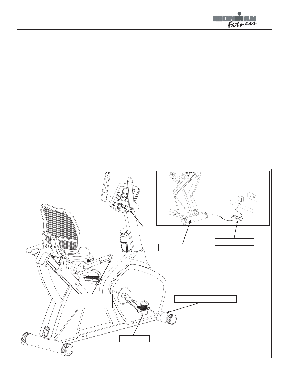
Please review the following drawing below to familiarize yourself with the listed
parts.
PULSE GRIP
HANDLEBARS
CONSOLE
AC ADAPTER
REAR STABILIZER
FRONT STABILIZER
PEDAL
4
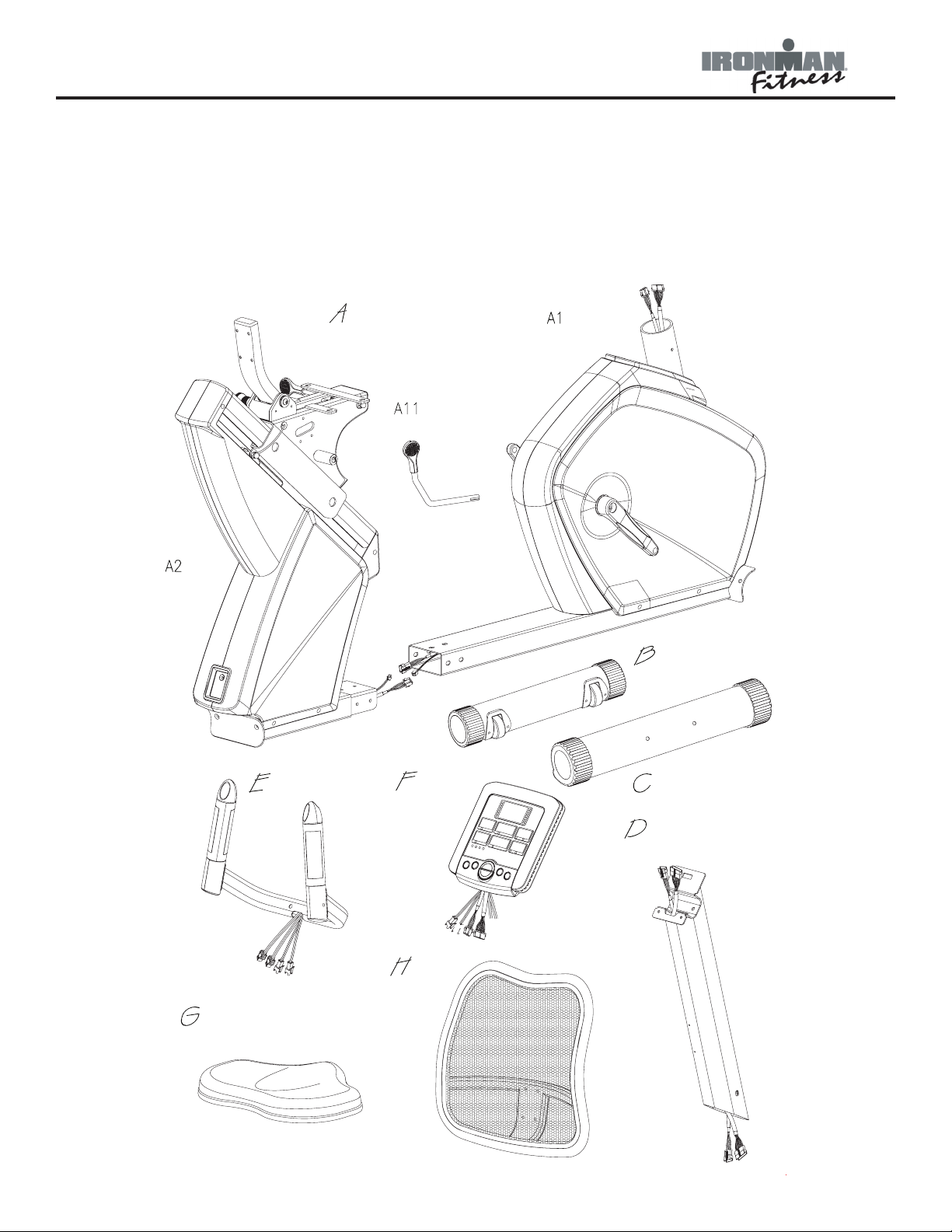
Parts Identifier
Seat Slide
Adjustment
Handle
Main Frame
Front
Rear
Handle Bar
Console
Front Stabilizer
Rear Stabilizer
Main Support Tube
Back
Rest
Seat Pad
INSTRUCTIONS FOR ASSEMBLY:
Unpack the box in a clear area. Check to make sure all components are present and in good
condition. Do not dispose of the packing material until the assembly is completed. Tools have
been provided for you to use when assembling this product.
Locate the hardware pack and identify the following parts required for assembly.
5
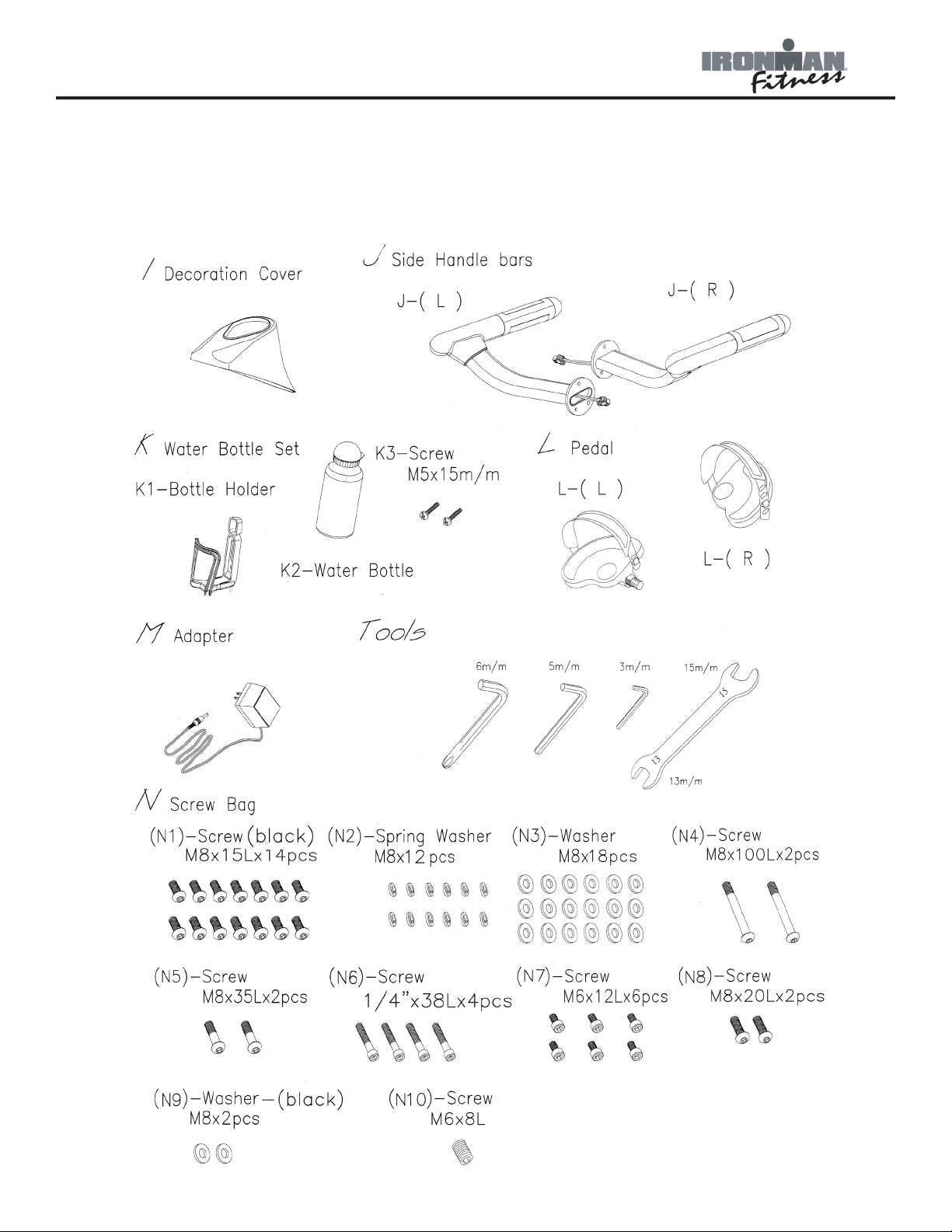
Parts Identifier
INSTRUCTIONS FOR ASSEMBLY:
Unpack the box in a clear area. Check to make sure all components are present and in good
condition. Do not dispose of the packing material until the assembly is completed. Tools have
been provided for you to use when assembling this product.
6
Assembly
Getting Started - The Ironman Fitness Viper Recumbent Bike will require some assembly.
Unpack the box in a clear area. Remove packing material. Do not dispose of packing material
until assembly is complete and unit is working properly. Place the unit on a clean level surface
for assembly. Make sure there is easy access to an electrical outlet. Before assembling, the
unit should be placed as close as possible to its final location. If you are missing any parts,
please call Ironman Fitness at 1-800-750-4766. Tools have been provided to assist with product assembly.
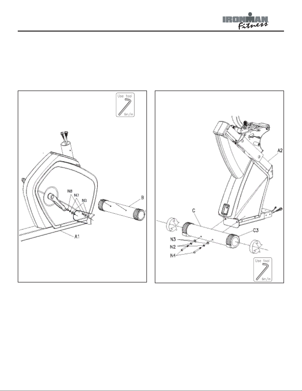
Figure 1
Figure 2
Figure 1
Step 1:
Secure front stabilizer bar (B) to main
frame (A1) using two bolts (N8), spring
washers (N2) and two washers (N3).
Note: Bolts will already be installed onto
the front stabilizer.
Figure 2
Step 1:
Secure rear stabilizer (C) to the main
frame (A2) using two bolts (N4), two spring
washers (N2) and two washers (N3).
7
Assembly
D
I
Figure 3
Step 1:
Connect hand pulse sensor wire-rear (A24)
to the hand pulse sensor wire-middle (A23).
Connect the power cord (A31) to power
cord (A32).
Step 2:
Locate the front (A1) and rear (A2) main
frames. Connect both front and rear
frames. To secure, use six bolts (N1), six
spring washers (N2) and six washers (N3) make sure all holes are lined up correctly.
Note: Ensure that all wires are secure
inside tube during the entire time both
frames are being secured. Be careful not to
pinch wires.
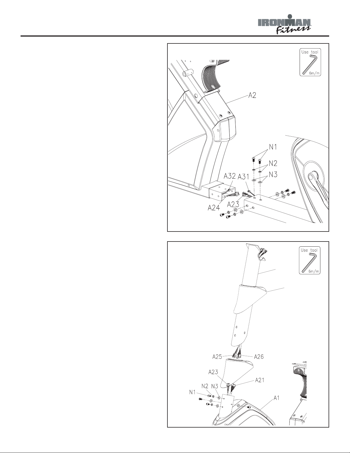
Figure 3
Figure 4
Step 1:
Locate main support tube (D) and console
tube cover (I). Slide main tube cover up
the main support tube.
Step 2:
Connect hand pulse sensor wire - front
(A25) coming from main support tube to
hand sensor wire - middle (A23) coming
from the main frame.
Connect power wire (A26) coming from
main support tube (D) to power wire (A21)
coming from the main frame.
Step 3:
Secure main support tube to main frame
(A1) using four bolts (N1) and four spring
washers (N2) and two washers (N3). Slide
main support tube cover down until it meets
the main frame.
Figure 4
8
Assembly
N10
A9
N3
A9
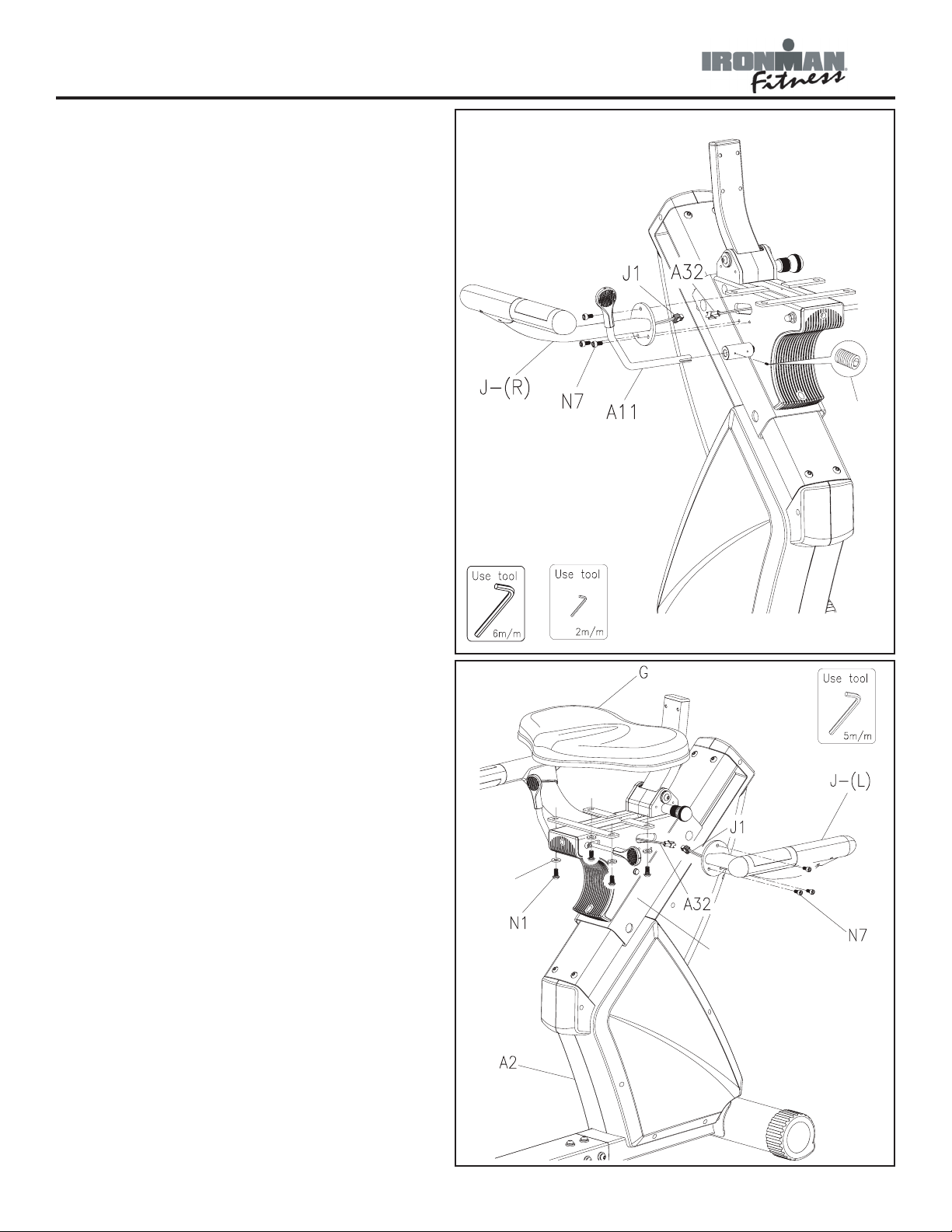
Figure 5
Step 1:
Slide the seat adjustment handlebar (A11)
into the main frame and secure using stopping screw (N10).
Step 2:
Connect sensor wire (A32) to sensor wire
(J1) and side handlebar (J-R) onto sliding
track (A9). Secure using three bolts (N7).
Figure 5
Figure 6
Step 1:
Connect sensor wires (A32) to sensor wire
(J1) and side handlebar (J-L) onto sliding
track (A9). Secure using three bolts (N7).
Step 2:
Locate seat pad (G) and secure onto slid-
ing track (A9) with four screws (N1) and
four washers (N3).
Figure 6
9
 Loading...