


 Loading...
iQ ®200 Sprint ™
Service Manual
Iris Diagnostics, a Division of Iris International, Inc.

Table of Contents |
1 - Introduction |
Intended Use...................................................................................................... |
1-2 |
How to use this Manual ...................................................................................... |
1-2 |
Precautions and Warnings ................................................................................. |
1-4 |
Notes .................................................................................................................. |
1-4 |
Cautions ............................................................................................................. |
1-4 |
Warnings ............................................................................................................ |
1-4 |
Biological Warning.............................................................................................. |
1-4 |
Warranty............................................................................................................. |
1-5 |
Limitation of Liability ........................................................................................... |
1-6 |
Use of Third Party Computer Products .............................................................. |
1-6 |
Iris Diagnostics Contact Information................................................................... |
1-7 |
2 - Installation Procedures
Installation Requirements................................................................................... |
2-2 |
Space Requirements.......................................................................................... |
2-2 |
Workstation ........................................................................................................ |
2-2 |
Location.............................................................................................................. |
2-2 |
Requirements ..................................................................................................... |
2-2 |
Installation .......................................................................................................... |
2-2 |
Shipping Cartons................................................................................................ |
2-3 |
Instrument Carton............................................................................................... |
2-3 |
Starter Kit A Carton ............................................................................................ |
2-4 |
Starter Kit B Carton (needs refrigeration)........................................................... |
2-4 |
Optional .............................................................................................................. |
2-4 |
Installation .......................................................................................................... |
2-5 |
Precautions ........................................................................................................ |
2-5 |
Connecting the Sampler..................................................................................... |
2-6 |
Adjust the Height of the Analyzer ....................................................................... |
2-6 |
Adjust Sampler ................................................................................................... |
2-7 |
Installing the Lamina Container.......................................................................... |
2-7 |
Connecting the Drain Tubing.............................................................................. |
2-7 |
Computer Connections....................................................................................... |
2-8 |
iQ200 Rear Panel SIC Connection Configurations ............................................ |
2-9 |
iQ200 / AX-4280 Connection Bridge Instructions............................................. |
2-10 |
Optional Load/Unload Station Installation ........................................................ |
2-15 |
Load Station - iQ200 Connection ..................................................................... |
2-15 |
Load Station - AX-4280 Connection................................................................. |
2-17 |
Unload Station.................................................................................................. |
2-19 |
Startup.............................................................................................................. |
2-21 |
Run Focus ........................................................................................................ |
2-22 |
Iris Diagnostics, a Division of Iris International, Inc.
iQ |
® |
Sprint™ (2G) Automated Urine Microscopy Analyzer Service Manual 300-4949 Rev A 01/2005 |
1 |
200 |

Table of Contents |
Run Calibration Rack ....................................................................................... |
2-22 |
Run Control Rack ............................................................................................. |
2-22 |
Verify Load/Unload and Bridge Connections ................................................... |
2-22 |
Preparation for Starting Operation ................................................................... |
2-22 |
Perform Setup .................................................................................................. |
2-22 |
3 – Components
Sample Transport Mechanism ........................................................................... |
3-3 |
Sampler # 700-3006........................................................................................... |
3-3 |
Specimen Tube Detector # 700-3725 ................................................................ |
3-4 |
Barcode Reader # 700-3315 .............................................................................. |
3-5 |
Specimen Presentation Assembly # 700-3700 .................................................. |
3-6 |
Crash Detect Function........................................................................................ |
3-6 |
Waste/Rinse Well # 700-3830............................................................................ |
3-7 |
Diaphragm Pumps.............................................................................................. |
3-8 |
Air Pump # 700-3877 ......................................................................................... |
3-8 |
Waste Pump # 700-3809.................................................................................... |
3-8 |
Rinse Pump # 700-3874..................................................................................... |
3-8 |
Fill Pump # 700-3874 ......................................................................................... |
3-8 |
Peristaltic Pumps # 700-3820 .......................................................................... |
3-10 |
Cannula Pump.................................................................................................. |
3-10 |
Lamina Pump ................................................................................................... |
3-10 |
Evacuation Pump ............................................................................................. |
3-10 |
Pump Cover Closed and Cassette-In-Place Detection .................................... |
3-10 |
Lamina Tank # 700-3784 ................................................................................. |
3-12 |
Air Tank # 700-3802......................................................................................... |
3-13 |
Valves............................................................................................................... |
3-14 |
Solenoid Valves................................................................................................ |
3-14 |
Drain Valve # 700-3844.................................................................................... |
3-14 |
Evacuation Bypass Valve # 700-3843.............................................................. |
3-14 |
Lamina Bypass Valve # 700-3842.................................................................... |
3-14 |
Cannula Bypass Valve # 700-3881 .................................................................. |
3-14 |
Pipettor Bypass Valve # 700-3880 ................................................................... |
3-14 |
Air Valves ......................................................................................................... |
3-15 |
Air Mix Valve # 700-3887 ................................................................................. |
3-15 |
Air Charge Valve # 700-3888 ........................................................................... |
3-15 |
Optical Bench Assembly #700-3500 ................................................................ |
3-16 |
Flow Cell # 525-3077 ....................................................................................... |
3-17 |
Strobe Light # 065-0059................................................................................... |
3-17 |
CCD Camera # 700-3565................................................................................. |
3-17 |
20 x Objective # 220-3009 ............................................................................... |
3-17 |
Auto Focus System # 700-3505 ....................................................................... |
3-17 |
Power System Assembly # 230-3000 .............................................................. |
3-18 |
Iris Diagnostics, a Division of Iris International, Inc.
iQ |
® |
Sprint™ (2G) Automated Urine Microscopy Analyzer Service Manual 300-4949 Rev A 01/2005 |
2 |
200 |

Table of Contents |
Cooling Fans # 700-3892 & 700-3412 ............................................................. |
3-18 |
Fuses and Visible LEDs ................................................................................... |
3-18 |
Backplane Fuses and LEDs ............................................................................. |
3-19 |
PCBA Summary ............................................................................................... |
3-21 |
Cardcage.......................................................................................................... |
3-22 |
High Level Control Board (HLCB), # 101-5000 ................................................ |
3-22 |
Motor/Scanner Control Board (MSCB), # 101-5001......................................... |
3-22 |
DC Valve Board (DCVB), # 101-5043 .............................................................. |
3-22 |
Stepper/Scanner/Motor Board (SSMB), # 101-5007........................................ |
3-23 |
Backplane # 101-5003 ..................................................................................... |
3-23 |
Signal Interface Concentrators (SICs).............................................................. |
3-24 |
Power SIC # 101-5020 ..................................................................................... |
3-24 |
Pump SIC #101-5020....................................................................................... |
3-25 |
FSV SIC # 101-5045 ........................................................................................ |
3-25 |
SPA SIC # 101-5004 ........................................................................................ |
3-27 |
SPA SIC Visible LEDs...................................................................................... |
3-27 |
SPA SIC Push-Button Switches ....................................................................... |
3-27 |
OBA SIC #101-5053......................................................................................... |
3-28 |
Do-All SIC # 101-5046 ..................................................................................... |
3-29 |
Rear Panel SIC # 101-5030 ............................................................................. |
3-30 |
STM SIC # 101-5014........................................................................................ |
3-30 |
Other PCBAs.................................................................................................... |
3-30 |
ESN Board # 101-5049 .................................................................................... |
3-30 |
Lamina ESN # 101-5048 .................................................................................. |
3-30 |
FITD PCBA # 101-5041 ................................................................................... |
3-30 |
SM Status Board PCBA # 101-5032 ................................................................ |
3-31 |
STD PCBA # 101-5034 .................................................................................... |
3-31 |
Pressure Transducer Board #101-5016 ........................................................... |
3-31 |
SPA Optical Board # 101-5052 ........................................................................ |
3-31 |
LED Visual Indicators ....................................................................................... |
3-31 |
4 – Adjustments
Accessing the Service Screen............................................................................ |
4-3 |
Calibration Table ................................................................................................ |
4-4 |
Calibration Auto-Sets ......................................................................................... |
4-4 |
Sampler Calibration............................................................................................ |
4-6 |
Material required ................................................................................................ |
4-6 |
Procedure........................................................................................................... |
4-6 |
Specimen Tube Detector Alignment................................................................... |
4-7 |
Material required ................................................................................................ |
4-7 |
Procedure........................................................................................................... |
4-7 |
Specimen Tube Detector Calibration ................................................................. |
4-8 |
Material required ................................................................................................ |
4-8 |
Iris Diagnostics, a Division of Iris International, Inc.
iQ |
® |
Sprint™ (2G) Automated Urine Microscopy Analyzer Service Manual 300-4949 Rev A 01/2005 |
3 |
200 |

Table of Contents |
Procedure........................................................................................................... |
4-8 |
STD Verification Procedure................................................................................ |
4-9 |
Specimen Presentation Assembly (SPA) and Waste/Rinse Well Calibration .. |
4-10 |
Material required .............................................................................................. |
4-10 |
Procedure......................................................................................................... |
4-10 |
Waste Well Positioning..................................................................................... |
4-10 |
Test Tube Centering Position........................................................................... |
4-11 |
Test Tube Depth Positioning ............................................................................ |
4-11 |
Waste Well Depth Positioning .......................................................................... |
4-12 |
Lamina Consumption Adjustment .................................................................... |
4-12 |
Air Pressure Calibration ................................................................................... |
4-13 |
Material required .............................................................................................. |
4-13 |
Procedure......................................................................................................... |
4-13 |
Barcode Reader Alignment .............................................................................. |
4-14 |
Material Required ............................................................................................. |
4-14 |
Procedure......................................................................................................... |
4-14 |
Prepare Barcode Reader Connections ............................................................ |
4-14 |
Load the Alignment Tool .................................................................................. |
4-15 |
Perform barcode alignment .............................................................................. |
4-15 |
Validation.......................................................................................................... |
4-18 |
Collimation........................................................................................................ |
4-19 |
What is a Collimation?...................................................................................... |
4-19 |
Condenser Alignment....................................................................................... |
4-19 |
Run Auto Focus................................................................................................ |
4-20 |
Flow Cell Replacement .................................................................................... |
4-21 |
Flow Cell Removal ........................................................................................... |
4-21 |
Flow Cell Installation ........................................................................................ |
4-21 |
Flow Cell Lateral Adjustment............................................................................ |
4-22 |
Flow Cell Tilt Adjustment.................................................................................. |
4-23 |
5 - Service Application Software
Accessing the Service Screen............................................................................ |
5-3 |
Startup................................................................................................................ |
5-3 |
Establishing Link ................................................................................................ |
5-4 |
Live Operation .................................................................................................... |
5-5 |
Tree View Pane.................................................................................................. |
5-5 |
Commands ......................................................................................................... |
5-6 |
Preset Moves ..................................................................................................... |
5-6 |
Sensors .............................................................................................................. |
5-6 |
Register 0x0A..................................................................................................... |
5-7 |
Calibration Table ................................................................................................ |
5-7 |
Calibration Auto-Sets ......................................................................................... |
5-7 |
Sequences ......................................................................................................... |
5-7 |
Iris Diagnostics, a Division of Iris International, Inc.
iQ |
® |
Sprint™ (2G) Automated Urine Microscopy Analyzer Service Manual 300-4949 Rev A 01/2005 |
4 |
200 |

Table of Contents |
Fluid Schematic Pane ........................................................................................ |
5-8 |
Diaphragm Pumps.............................................................................................. |
5-8 |
Peristaltic Pumps................................................................................................ |
5-8 |
3-Way Valves ..................................................................................................... |
5-9 |
2-Way Valves ..................................................................................................... |
5-9 |
Motors ................................................................................................................ |
5-9 |
Tube Connectors.............................................................................................. |
5-10 |
Other Regions of Interest ................................................................................. |
5-10 |
Menu Bar.......................................................................................................... |
5-10 |
File Menu.......................................................................................................... |
5-10 |
View Event Log ................................................................................................ |
5-10 |
Show Versions Report...................................................................................... |
5-11 |
Exit ................................................................................................................... |
5-11 |
Edit Menu ......................................................................................................... |
5-11 |
View Menu........................................................................................................ |
5-11 |
Toolbar ............................................................................................................. |
5-11 |
Status Bar......................................................................................................... |
5-12 |
Polling............................................................................................................... |
5-12 |
Video ................................................................................................................ |
5-12 |
Record Video Statistics .................................................................................... |
5-12 |
Terminal ........................................................................................................... |
5-12 |
Jog Menu.......................................................................................................... |
5-13 |
Status Bar......................................................................................................... |
5-13 |
Current Message Status................................................................................... |
5-13 |
Link Status........................................................................................................ |
5-14 |
“Starting ASTM”................................................................................................ |
5-14 |
“Establishing link (may take a minute)” ............................................................ |
5-14 |
“Could not establish link”.................................................................................. |
5-15 |
Troubleshooting Failure to Establish Link ........................................................ |
5-15 |
“Connection established”.................................................................................. |
5-15 |
“Sending initialization messages”..................................................................... |
5-16 |
“Sending initial query messages” ..................................................................... |
5-16 |
“Sending query messages” .............................................................................. |
5-16 |
“Idle” ................................................................................................................. |
5-16 |
Caps Lock Status ............................................................................................. |
5-16 |
Num Lock Status .............................................................................................. |
5-16 |
Scroll Lock Status............................................................................................. |
5-16 |
Sequences & Sensor Identifications for Troubleshooting................................. |
5-17 |
Master (Master Controller) ............................................................................... |
5-17 |
Sequences ....................................................................................................... |
5-17 |
Level sensors ................................................................................................... |
5-17 |
SPA .................................................................................................................. |
5-17 |
Pumps/Evacuation pump/Sensors ................................................................... |
5-18 |
STM.................................................................................................................. |
5-18 |
Iris Diagnostics, a Division of Iris International, Inc.
iQ |
® |
Sprint™ (2G) Automated Urine Microscopy Analyzer Service Manual 300-4949 Rev A 01/2005 |
5 |
200 |

Table of Contents |
Sensors ............................................................................................................ |
5-18 |
FBA .................................................................................................................. |
5-18 |
Pumps/Sheath pump/Sensors.......................................................................... |
5-18 |
Pumps/Cannula pump/Sensors........................................................................ |
5-18 |
Program Operation........................................................................................... |
5-19 |
Frequently Asked Questions (FAQ) ................................................................. |
5-19 |
Why Does a Sensor Display the Wrong Value?............................................... |
5-19 |
Which Controller Does Component X (Pump, Valve, etc.) Belong To? ........... |
5-19 |
What Are the Communication Addresses of the Major System Components? 5-20 |
|
What Should I Do If the Service Application Appears to Hang?....................... |
5-20 |
Service Tree ..................................................................................................... |
5-21 |
Master .............................................................................................................. |
5-21 |
SPA Motors ...................................................................................................... |
5-22 |
SPA Pumps and Valves ................................................................................... |
5-23 |
FBA Pumps and Sequences ............................................................................ |
5-25 |
STM Motors 1................................................................................................... |
5-26 |
STM Motors 2, Sensors, Calibration Table and Sequences ............................ |
5-27 |
OBA.................................................................................................................. |
5-28 |
Versions 1 ........................................................................................................ |
5-29 |
Versions 2 ........................................................................................................ |
5-30 |
6 - Troubleshooting
Bypassing Error Condition.................................................................................. |
6-2 |
Decoding the Valves field in Valve Error Reports .............................................. |
6-2 |
Iris Diagnostics Contact Information................................................................... |
6-2 |
Troubleshooting Guide ....................................................................................... |
6-3 |
System locked up ............................................................................................... |
6-3 |
Autofocus failed.................................................................................................. |
6-3 |
IQ 200 fails to go to Standby .............................................................................. |
6-4 |
ID errors ............................................................................................................. |
6-4 |
Illumination/Sequential errors............................................................................. |
6-5 |
Valve failure to open or close ............................................................................. |
6-5 |
System does not go into Standby mode............................................................. |
6-5 |
Samples take more than 60 secs to process and complete............................... |
6-5 |
Positive control failure ........................................................................................ |
6-5 |
Calibration rack failed......................................................................................... |
6-5 |
Non uniform flow in Runfile ................................................................................ |
6-6 |
Inconsistent cell count from run to run in Runfile ............................................... |
6-6 |
SP-FLI (spatial flow index) is high in all Runfiles................................................ |
6-6 |
SP-KSP are high in all Runfiles.......................................................................... |
6-6 |
Bubbles are present in fluid system ................................................................... |
6-6 |
Waste well overflow............................................................................................ |
6-6 |
Event Log Error Messages................................................................................. |
6-7 |
Iris Diagnostics, a Division of Iris International, Inc.
iQ |
® |
Sprint™ (2G) Automated Urine Microscopy Analyzer Service Manual 300-4949 Rev A 01/2005 |
6 |
200 |

Table of Contents |
7 - Electronics |
Electronics.......................................................................................................... |
7-2 |
General Functions .............................................................................................. |
7-2 |
Cabling Diagram Overview................................................................................. |
7-3 |
View of Backplane inside Cardcage................................................................... |
7-4 |
Rear view of Backplane -- Fuses and Connections to Internal parts of Microscopy
Module................................................................................................................ |
7-5 |
Addresses and Summary ................................................................................... |
7-6 |
Hardware Bit Assignments and Details ............................................................ |
7-11 |
Hardware Assignment Cross Reference .......................................................... |
7-21 |
ESN I2C Addresses ......................................................................................... |
7-27 |
8 - Schematics
998-3006 |
SM SMCS Assemblies Block Diagram |
...............................................8-3 |
700-3800 |
System Fluid Assembly...................................................................... |
8-4 |
Master Controller State records ......................................................................... |
8-5 |
|
SPA State records............................................................................................ |
8-21 |
|
FBA State records ............................................................................................ |
8-25 |
|
STM State records ........................................................................................... |
8-27 |
|
9 - Preventive Maintenance
Material............................................................................................................... |
9-2 |
Semi-Annual PM kit Part Number 799-3050 ...................................................... |
9-2 |
Annual PM Kit Part Number 799-3051 .............................................................. |
9-2 |
Cleaning ............................................................................................................. |
9-3 |
Instrument Clean Up .......................................................................................... |
9-3 |
Fluidics Clean Up ............................................................................................... |
9-3 |
Rinse/Waste Well Clean Up ............................................................................... |
9-3 |
Air blow............................................................................................................... |
9-3 |
Computers Clean Up.......................................................................................... |
9-3 |
Laser Printer....................................................................................................... |
9-3 |
Fluidics ............................................................................................................... |
9-4 |
Liquid Waste....................................................................................................... |
9-4 |
Peristaltic pump cassette replacement............................................................... |
9-4 |
Tubing replacements.......................................................................................... |
9-4 |
Adjustment verification ....................................................................................... |
9-5 |
Sampler Rack alignment .................................................................................... |
9-5 |
Specimen Tube Detector verification ................................................................. |
9-5 |
Barcode Reader alignment verification .............................................................. |
9-5 |
SPA alignment verification ................................................................................. |
9-5 |
|
|
Iris Diagnostics, a Division of Iris International, Inc.
iQ |
® |
Sprint™ (2G) Automated Urine Microscopy Analyzer Service Manual 300-4949 Rev A 01/2005 |
7 |
200 |

Table of Contents |
Fluidic inspection................................................................................................ |
9-6 |
Autofocus run ..................................................................................................... |
9-6 |
Optical Bench Verification .................................................................................. |
9-6 |
Replenish Consumables .................................................................................... |
9-6 |
Performance verification..................................................................................... |
9-7 |
Software ............................................................................................................. |
9-7 |
Calibration run .................................................................................................... |
9-7 |
Control run.......................................................................................................... |
9-7 |
Documenting the Preventive Maintenance......................................................... |
9-7 |
Iris Diagnostics, a Division of Iris International, Inc.
iQ |
® |
Sprint™ (2G) Automated Urine Microscopy Analyzer Service Manual 300-4949 Rev A 01/2005 |
8 |
200 |

1. Introduction |
|
1 |
|
Introduction |
Intended Use.................................................................................................................. |
1-2 |
How to use this Manual.................................................................................................. |
1-2 |
Precautions and Warnings ............................................................................................. |
1-4 |
Notes .......................................................................................................................... |
1-4 |
Cautions ..................................................................................................................... |
1-4 |
Warnings .................................................................................................................... |
1-4 |
Biological Warning...................................................................................................... |
1-4 |
Warranty......................................................................................................................... |
1-5 |
Limitation of Liability....................................................................................................... |
1-6 |
Use of Third Party Computer Products .......................................................................... |
1-6 |
Iris Diagnostics Contact Information .............................................................................. |
1-7 |
Iris Diagnostics, a Division of Iris International, Inc.
iQ |
® |
Sprint™ (2G) Automated Urine Microscopy Analyzer Service Manual 300-4949 Rev A 01/2005 |
1-1 |
200 |
1. Introduction |
Intended Use
This Service Manual is intended for the iQ®200 Sprint and the iQ®200 2nd generation Automated Urine Microscopy Analyzer – HVL (High Volume Laboratory).
There are two HVL configurations:
•The iQ®200 Sprint can process 101 samples per hour
•The iQ200 2nd generation can process 60 samples per hour
These instruments have a new fluidic design, the capability of connecting Load and Unload stations, and improved error reporting.
The iQ®200 Sprint™ Automated Urinalysis System (iQ®200 System) is an invitro diagnostic use device composed of the iQ®200 Automated Urine Microscopy Analyzer (iQ®200), connected physically and electronically to the AUTION MAX™ AX-4280 Automated Urine Chemistry Analyzer (AX4280), and a workstation. The iQ®200 System is used to automate the complete routine urinalysis profile, including urine test strip chemistry panel, specific gravity, color, clarity, and microscopic analysis, providing quantitative or qualitative counts of formed elements, such as cells, casts, crystals, and organisms.
Optionally, the iQ®200 Automated Urine Microscopy Analyzer can be used as a stand-alone device for microscopic analysis, and the results from the iQ®200 can be combined with other urine chemistry results.
This manual is intended to be used by Iris Diagnostics trained personnel.
How to use this Manual
References are made to other sections within the Manual. In order to avoid searching for a specific document or section, electronic hyperlinks have been created to let you jump to other locations and to give you immediate access to related information.
Iris Diagnostics, a Division of Iris International, Inc.
iQ |
® |
Sprint™ (2G) Automated Urine Microscopy Analyzer Service Manual 300-4949 Rev A 01/2005 |
1-2 |
200 |
1. Introduction |
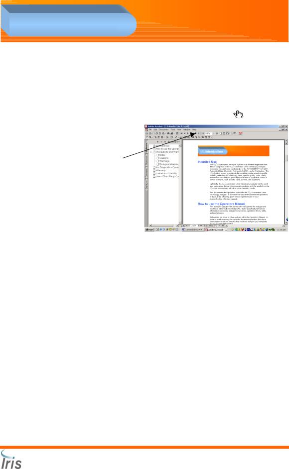
To follow a link:
1.Select the hand tool 
2.Links are indicated in the following manner:
•The text is colored blue and underlined. Example: Iris Diagnostics Contact Information.
3.Position the pointer over the linked area on the page until the pointer
changes to the hand with a pointing finger |
. Then click the link. |
4.To return to the previous section, click on the Go to Previous View button.
5.The Bookmark pane, located on the left side of the screen, can be used as a “linked” table of contents. Click on the + or - sign located next to the title to expand or collapse the selection for a bookmark. Clicking on
a bookmark will take you automatically to the starting page of the selected section.
Iris Diagnostics, a Division of Iris International, Inc.
iQ |
® |
Sprint™ (2G) Automated Urine Microscopy Analyzer Service Manual 300-4949 Rev A 01/2005 |
1-3 |
200 |
1. Introduction |
Precautions and Warnings
The Manual includes information and warnings that must be observed by the operator to ensure safe operation of the system. Important messages are highlighted with borders and special icons identifying the type of message enclosed.
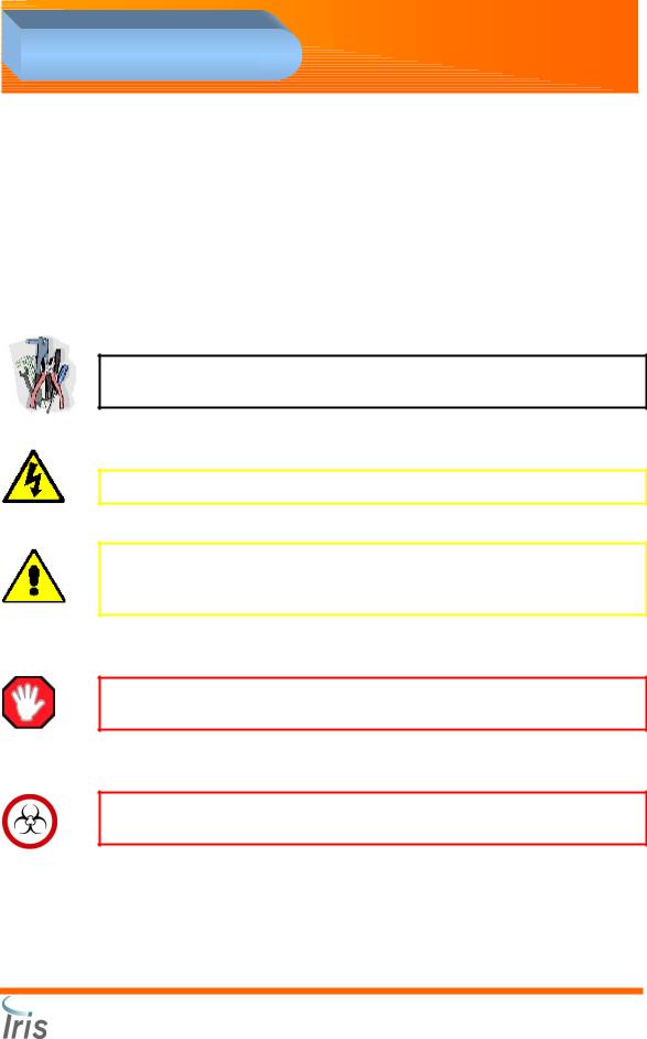
There are four types of messages.
Notes
NOTE: Highlights important facts, gives helpful information and tips, and clarifies procedures.
Cautions
CAUTION: Electrical caution! Unplug before handling.
CAUTION: If any liquid is spilled onto the Sampler, wipe the area clean before testing. Leaving the spill may cause crystals to form and block the movement of the sample racks.
Warnings
WARNING: Identifies potentially hazardous situations that could result in serious injury to laboratory personnel.
Biological Warning
WARNING: Wear protective gloves to prevent exposure to pathogens. Discard contaminated materials according to applicable regulations.
Iris Diagnostics, a Division of Iris International, Inc.
iQ |
® |
Sprint™ (2G) Automated Urine Microscopy Analyzer Service Manual 300-4949 Rev A 01/2005 |
1-4 |
200 |

1. Introduction |
Warranty
Iris Diagnostics, a subsidiary of Iris International, (Iris) warrants that the products manufactured by it, its divisions or subsidiaries and sold hereunder shall be free from defects in material and/or workmanship, under normal use and service, for the period expiring twelve (12) months from the completion of installation under standard procedure by Iris Diagnostics or an authorized Iris Diagnostics distributor, or upon Purchaser’s signature on Iris Warranty/Acceptance form, or eighteen (18) months from shipment, whichever occurs first. Iris Diagnostics makes no warranty whatsoever regarding products manufactured by persons other than Iris Diagnostics, its Divisions or Subsidiaries and Purchaser’s sole source of warranty therefore, if any, is the original manufacturer’s warranty.
No warranty extended by Iris Diagnostics shall apply to any products which have been modified, altered, or repaired by persons others than those authorized or approved by Iris or to products sold as “used.”
Iris Diagnostics’ obligation under this warranty is limited SOLELY to the repair or replacement, at Iris Diagnostics’ option, of defective parts, F.O.B. warehouse or local Iris office, or as otherwise specified by Iris. Repairs or replacement deliveries shall not interrupt or prolong the term of this warranty. Iris Diagnostics warranty does not apply to consumable materials, except as specially stated in writing, not to products or parts thereof manufactured by Purchaser.
This limited warranty is made on condition that immediate written notice of any defect be given to Iris Diagnostics and that Iris inspection reveals that the Purchaser’s claim is valid under the terms of this warranty.
Iris Diagnostics makes no warranty other than the one set forth herein or that which may be provided in a separate warranty covering the applicable product category. Such limited warranty is in lieu of all other warranties, expressed or implied, including but not limited to any expressed or implied warranty of merchantability or fitness for particular purposes and such constitutes the only warranty made with respect to the products.
Iris Diagnostics, a Division of Iris International, Inc.
iQ |
® |
Sprint™ (2G) Automated Urine Microscopy Analyzer Service Manual 300-4949 Rev A 01/2005 |
1-5 |
200 |

1. Introduction |
Limitation of Liability
Iris Diagnostics shall not be liable for any loss of use, revenue or anticipated profits, or for any consequential or incidental damages resulting from the sale or use of the products.
Use of Third Party Computer Products
Iris Diagnostics does not recommend that the workstation provided as a functional part of the iQ®200 Automated Urine Microscopy Analyzer or the iQ®200 System be employed for performing any software or hardwarebased applications other than those specifically furnished to operate and support the Iris instrument system, or those recommended and offered by Iris Diagnostics specifically as accessories or enhancements for the Iris instrument system. No other third party application software should be installed in these microcomputers in addition to those provided or recommended by Iris Diagnostics, without the expressed approval of Iris Diagnostics Technical Services, in order to avoid potential performance and reliability problems which can result from incompatibility factors, errors in use of such software, or software-based “viruses.”
Installation of such third party software, or non-approved electronic cards or other devices, without advance Iris Diagnostics approval may affect the terms of or void any Iris Diagnostics warranty otherwise in effect, covering Iris Diagnostics supplied software and hardware on the microcomputers and the overall performance and reliability of the entire Iris Diagnostics instrument system.
Iris Diagnostics, a Division of Iris International, Inc.
iQ |
® |
Sprint™ (2G) Automated Urine Microscopy Analyzer Service Manual 300-4949 Rev A 01/2005 |
1-6 |
200 |

1. Introduction |
Iris Diagnostics Contact Information
Iris Diagnostics
A Division of Iris International, Inc.
9172 Eton Avenue
Chatsworth, CA 91311
USA
Telephone: |
|
From U.S. locations |
(800) PRO-IRIS (776-4747) |
From outside the U.S. |
+1-818-709-1244 |
Fax: +1-(818) 700-9661
e-mail: sales@proiris.com
Iris Diagnostics, a Division of Iris International, Inc.
iQ |
® |
Sprint™ (2G) Automated Urine Microscopy Analyzer Service Manual 300-4949 Rev A 01/2005 |
1-7 |
200 |

2. Installation Procedures |
2
Installation |
|
Procedures |
|
Installation Requirements .............................................................................................. |
2-2 |
Space Requirements .................................................................................................. |
2-2 |
Workstation................................................................................................................. |
2-2 |
Location...................................................................................................................... |
2-2 |
Requirements ............................................................................................................. |
2-2 |
Installation .................................................................................................................. |
2-2 |
Shipping Cartons ........................................................................................................... |
2-3 |
Instrument Carton....................................................................................................... |
2-3 |
Starter Kit A Carton .................................................................................................... |
2-4 |
Starter Kit B Carton (needs refrigeration) ................................................................... |
2-4 |
Optional ...................................................................................................................... |
2-4 |
Installation...................................................................................................................... |
2-5 |
Precautions................................................................................................................. |
2-5 |
Connecting the Sampler ............................................................................................. |
2-6 |
Adjust the Height of the Analyzer ............................................................................... |
2-6 |
Adjust Sampler ........................................................................................................... |
2-7 |
Installing the Lamina Container .................................................................................. |
2-7 |
Connecting the Drain Tubing...................................................................................... |
2-7 |
Computer Connections............................................................................................... |
2-8 |
iQ200 Rear Panel SIC Connection Configurations..................................................... |
2-9 |
iQ200 / AX-4280 Connection Bridge Instructions ..................................................... |
2-10 |
Optional Load/Unload Station Installation ................................................................ |
2-16 |
Load Station - iQ200 Connection.......................................................................... |
2-16 |
Load Station - AX-4280 Connection ..................................................................... |
2-20 |
Unload Station ...................................................................................................... |
2-24 |
Startup ......................................................................................................................... |
2-27 |
Run Focus ................................................................................................................ |
2-28 |
Run Calibration Rack................................................................................................ |
2-28 |
Run Control Rack ..................................................................................................... |
2-28 |
Verify Load/Unload and Bridge Connections............................................................ |
2-28 |
Preparation for Starting Operation ............................................................................... |
2-29 |
Perform Setup....................................................................................................... |
2-29 |
Iris Diagnostics, a Division of Iris International, Inc.
iQ |
® |
Sprint™ (2G) Automated Urine Microscopy Analyzer Service Manual 300-4949 Rev A 01/2005 |
2-1 |
200 |

2. Installation Procedures |
Installation Requirements
Space Requirements
The iQ®200 is a tabletop unit requiring free space on a standard (36 inch: 0.9m) height countertop of approximately 36 inches wide by 24 inches deep (91cm by 61cm), with vertical clearance of at least 24 inches (61cm).
With optional Load and Unload stations, the width requirement is 60 inches (147 cm.)
Workstation
The Workstation is composed of a desktop computer, video monitor, keyboard and mouse requiring a suitable counter or desktop, providing comfortable access and a good viewing angle. It is suggested that, if possible, the WorkStation be placed in a work area, which can be semidarkened to increase screen display visibility and reduce glare.
The data connections are made between the iQ®200 and the Workstation (and the AX-4280 and the WorkStation, if applicable) via the special cables provided.
Location
For most laboratories, the iQ®200 is placed near an open benchtop work area which can be used for preparation of urine tubes and sample racks. All data transmissions from the iQ®200 (and the Ax-4280, if used) are routed to the Workstation, which manages and controls all communications to the Laboratory Information System (LIS) via serial connections.
Requirements
The iQ®200 uses 90 to 240V AC, 50-60Hz input source. Neither voltage nor frequency parameters are customer configurable. Uninterruptible power supplies are recommended and available from Iris Diagnostics for the iQ®200 and the Workstation (and the AX-4280 if applicable) to maintain system operation during short power outages and brownouts. This allows for an orderly shutdown of instruments without the loss of data.
Installation
The iQ®200 will be installed by a factory-trained representative from Iris
Diagnostics.
Iris Diagnostics, a Division of Iris International, Inc.
iQ |
® |
Sprint™ (2G) Automated Urine Microscopy Analyzer Service Manual 300-4949 Rev A 01/2005 |
2-2 |
200 |

2. Installation Procedures |
Shipping Cartons
The iQ®200 is shipped in three cartons.
Instrument Carton
Item number |
Description |
Qty |
|
800-3320 |
iQ®200 60/hour or |
1 |
|
800-3322 |
iQ®200 Sprint TM 101/hour |
||
|
|||
700-3103 |
Printer |
1 |
|
250-3082 |
Printer Cable |
1 |
|
700-3120 |
Computer Version 3.0 |
1 |
|
210-3004 |
Flat Panel Monitor |
1 |
|
700-3101 |
Keyboard and Mouse |
1 |
|
700-3022 |
Sample Racks (1 Set of 9) |
1 |
|
700-3008 |
Calibrator Rack |
1 |
|
700-3007 |
Control/Focus Rack |
1 |
|
700-3781 |
iQ Lamina Cap & Filter |
1 |
|
700-3701 |
Drain Tubing |
1 |
|
700-3702 |
Lamina Tubing |
1 |
|
250-3501 |
Serial Cable, PC to Microscopy Module |
1 |
|
700-3011 |
Operators Manual CD |
1 |
Iris Diagnostics, a Division of Iris International, Inc.
iQ |
® |
Sprint™ (2G) Automated Urine Microscopy Analyzer Service Manual 300-4949 Rev A 01/2005 |
2-3 |
200 |

2. Installation Procedures |
Starter Kit A Carton
|
|
Item number |
|
Description |
Qty |
|
475-0047 |
|
iQ®200 Lamina |
1 |
|
|
475-0021 |
|
Iris Diluent |
1 |
|
|
475-0003 |
|
Iris System Cleanser |
1 |
|
|
660-0036 |
|
Culture Tube, 16x100 250 pack |
1 |
|
|
800-3211 |
|
iQ®200 Dilution Labels Package |
1 |
|
Starter Kit B Carton (needs refrigeration) |
|
||||
|
|
Item number |
|
Description |
Qty |
|
|
800-3104 |
|
iQ®200 Control/Focus Set (four bottles) |
1 |
|
|
800-3103 |
|
iQ®200 Calibrator (four bottles) |
1 |
Optional |
|
|
|
||
|
|
Item number |
|
Description |
Qty |
|
|
800-3810 |
|
Load and Unload Set |
1 |
|
|
800-3514 |
|
Load Station (only) |
1 |
|
|
800-3515 |
|
Unload Station (only) |
1 |
|
|
800-3501 |
|
Ax-4280 Bridge Connection Kit |
1 |
Iris Diagnostics, a Division of Iris International, Inc.
iQ |
® |
Sprint™ (2G) Automated Urine Microscopy Analyzer Service Manual 300-4949 Rev A 01/2005 |
2-4 |
200 |
2. Installation Procedures |
Installation
To ensure safety, we advise you to read these installation instructions very carefully and take all proper precautions.
Precautions
The entire unit weighs approximately 140 lbs (63.5k). The Load and Unload Stations weigh 14 lbs (6.35) each. Choose a place to set up the unit before completing its assembly.
If the unit must be moved, separate the Sampler from the analyzer before moving. If these two units come apart while being carried, it may result in injury or severe damage.
Always keep a distance of at least 2 inches (5 cm) between the rear of the unit and the wall. If this distance is not maintained, the connecting tubes and cables may overheat and / or be subjected to mechanical stress.
Do NOT use power frequencies or voltage other than those specified in this document. Connection to an inappropriate power source may damage the instrument.
Make certain that the power supply for the iQ®200 is from a dedicated line that provides power to no other instruments or appliances. If power is not clean and steady, a UPS and/or power conditioner is recommended.
Do NOT disassemble or modify the unit. Doing so may cause injury and/or instrument malfunction.
Place the unit on a stable and level surface free of vibration. Failure to do so may cause injury or malfunction of the unit.
Do NOT place the unit where it may be affected by chemicals, corrosive gases or electronic noise. Doing so may cause injury or malfunction of the unit.
Do NOT place the unit where it may be affected by water, direct sunlight or draft. This may yield incorrect results, and the unit may be damaged.
Select a room to set up the unit where the temperature can be controlled between 50oF (10oC) and 86oF (30oC), and humidity in a range of 20% to 80%.
Iris Diagnostics, a Division of Iris International, Inc.
iQ |
® |
Sprint™ (2G) Automated Urine Microscopy Analyzer Service Manual 300-4949 Rev A 01/2005 |
2-5 |
200 |

2. Installation Procedures |
Unpacking the Instrument
Carefully remove the instrument from the shipping container. Remove all packing material from inside the instrument surrounding the SPA, the microscope and the waste well.
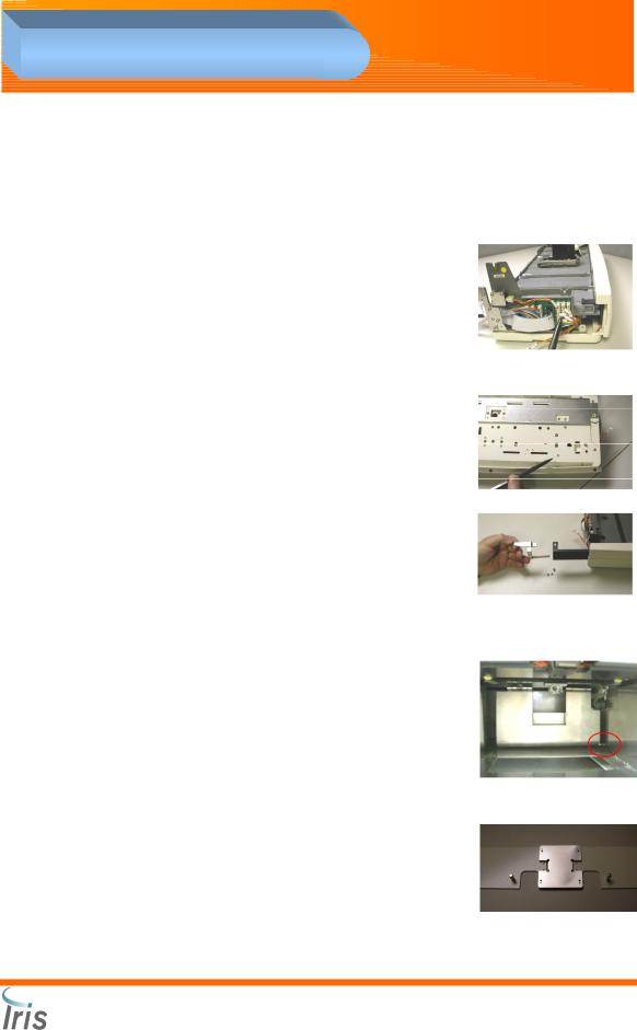
Connecting the Sampler
In order to protect the Analyzer and Sampler from damage during transport, each section is secured with tape. Follow the procedure below before installing the unit.
1. |
Remove the left side panel of |
|
|
|
the analyzer and the EMI |
|
|
|
shielding panel. |
|
|
2. |
Remove the four screws |
|
|
|
securing the STM SIC and |
|
|
|
diaphragm pumps. |
|
|
3. |
Connect the grey ribbon cable |
|
|
|
from the sampler to J01 on |
|
|
|
PCBA 101-5014 STM SIC. |
Ground |
|
4. |
Connect the multi-colored |
||
|
wiring cable to J02 on PCBA 101-5014 STM SIC.
5.Connect the black specimen tube detector cable to J9 on PCBA 1015014 STM SIC.
6.Connect the ground cables to the chassis of the microscopy module.
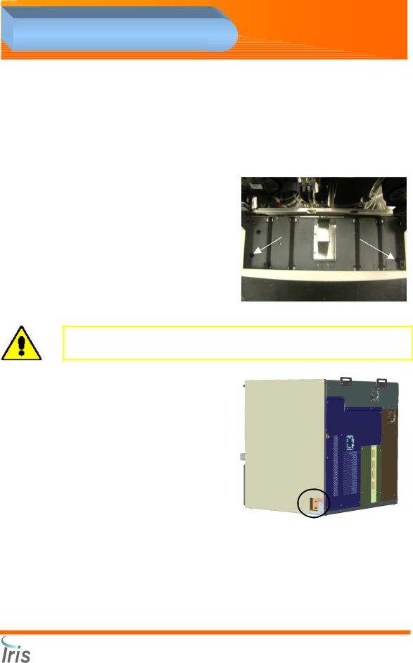
7.Insert the hooks of the sampler into the slots of the analyzer. Be careful not to catch the cables.
8.Reattach the STM SIC and diaphragm pumps to the chassis.
Adjust the Height of the Analyzer
• Using a 7/16” wrench, loosen the
|
locking nuts located under the |
|
|
|
analyzer. |
|
¾ inch |
• |
Adjust the height of the Sampler by |
|
|
|
|||
|
|
||
|
rotating the feet. The space between |
|
|
|
|
|
|
|
the bench top and the analyzer must |
|
|
|
be ¾ inch. |
|
|
•After adjusting the height, tighten the locking nuts.
Iris Diagnostics, a Division of Iris International, Inc.
iQ |
® |
Sprint™ (2G) Automated Urine Microscopy Analyzer Service Manual 300-4949 Rev A 01/2005 |
2-6 |
200 |
2. Installation Procedures |
Adjust Sampler
Two adjustment feet are located under the Sampler. They are accessed from the top of the Sampler. Each foot must be in contact with the benchtop.
•Using a flat head screwdriver, remove the two rubber caps located on the front corners of the Sampler. The top of the feet (screws) can be seen.
• Using a Phillips screwdriver (+), turn each of the two screws clockwise until the adjustment feet touch the bench top.
•Reinsert the rubber caps.
CAUTION: Make sure the height of the Sampler is adjusted correctly. Otherwise, the Sampler and the Probe may be damaged.
Installing the Lamina Container
•Install the Lamina cap with filter on a fresh Lamina container.
•Connect one end of the Lamina tubing to the top fitting on the right side of the analyzer. Connect the other end to the fitting of the Lamina cap.
Connecting the Drain Tubing
•Connect the drain tubing to the bottom fitting on the right side of the analyzer.
•The Drain Tubing can be directed to the designated waste area according to local regulations.
•If direct drainage is not an option, slide the Drain Tubing inside a waste container (approximately 2 in. (5cm)) Make sure the waste container is lower than the microscopy module.
Iris Diagnostics, a Division of Iris International, Inc.
iQ |
® |
Sprint™ (2G) Automated Urine Microscopy Analyzer Service Manual 300-4949 Rev A 01/2005 |
2-7 |
200 |

2. Installation Procedures |
Computer Connections
1.Connect the video monitor cable to the video monitor and the video port.
2.Connect the keyboard cable to the keyboard port.
3.Connect the mouse cable to the mouse port.
4.Connect the power cord into the power inlet, and then plug into an electrical outlet.
5.Connect the printer cable to the printer and the printer port.
6.Connect the 100-pin camera data cable to the frame grabber port.
7.Connect one end of the RS232 cable to the serial port on the
computer; connect the other end to the serial port 1 (top port) on the back of the iQ®200.
Iris Diagnostics, a Division of Iris International, Inc.
iQ |
® |
Sprint™ (2G) Automated Urine Microscopy Analyzer Service Manual 300-4949 Rev A 01/2005 |
2-8 |
200 |
2. Installation Procedures |
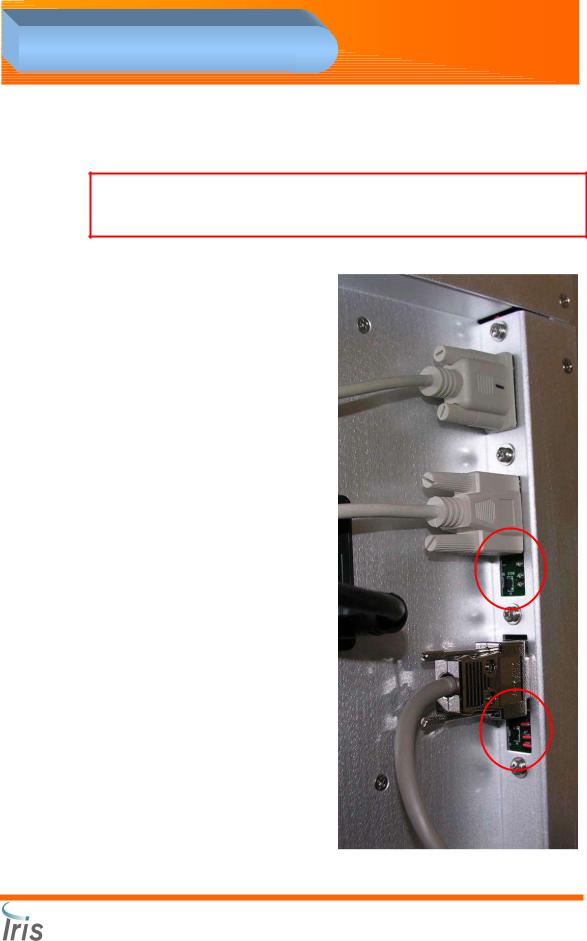
iQ200 Rear Panel SIC Connection Configurations
WARNING: Before making any connections to Load or Unload ports on the Rear Panel SIC of the iQ200, ensure the jumpers are in the correct configuration depending on the system options.
AX-4280 Connection to the iQ200
The second port labeled “Load” should have all three jumpers removed from the port. CAUTION! If the jumpers are not removed, a fuse will blow on the backplane of the card cage (F10) inside the Microscopy Module.
Load Station Connection to the iQ200
The second port labeled “Load” should have all three jumpers installed in the port. CAUTION! If the jumpers are not in place, the connection will not work and no power will be supplied to the Load Station.
Unload Station Connection to the iQ200
The third port labeled “Unload” should have all three jumpers installed in the port. CAUTION! If the jumpers are not in place, the connection will not work and no power will be supplied to the unload Station. Currently, the only configuration for this port is all three jumpers in place.
Iris Diagnostics, a Division of Iris International, Inc.
iQ |
® |
Sprint™ (2G) Automated Urine Microscopy Analyzer Service Manual 300-4949 Rev A 01/2005 |
2-9 |
200 |
2. Installation Procedures |
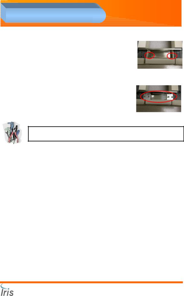
iQ200 / AX-4280 Bridge Installation Instructions
“iQ200-AX4280 Sample bridge kit” PN 800-3501.
1.Remove left side cover from the AX-4280 sampler.
2.Unplug connector # S1-10 (white label) from the circuit board and replace with connector# S1-10 (Side Sampler) stored in bottom of sampler.
3.At the bottom of the sampler, remove the screw (as indicated on the picture on the right) securing carry arm stop post. Remove the post from the sampler.
4.Extend the lever from the sampler. Attach the rack push arm to the lever with two (2, M3x5) flat head and one (1, M3x6 pan head) screws.
5.Break the tab on the side cover to allow the rack to transfer from the Load Station to the sampler.
6.Replace left side cover.
7.Back out the screw located inside the right frame of the test strip disposal compartment to hold the spring loaded return plate.
8.Install the new waste box provided with the connection kit.
9.Install an alignment bracket under each analyzer aligning the pins with the two holes located under the front of each instrument. Align the brackets and join with the connection bracket. Secure with four (4, M3x10 pan head) screws.
Iris Diagnostics, a Division of Iris International, Inc.
®
iQ 200 Sprint™ (2G) Automated Urine Microscopy Analyzer Service Manual 300-4949 Rev A 01/2005 2-10
2. Installation Procedures |
10.Install the bridge faceplate between the two samplers. Center and secure with the thumbscrews located underneath the faceplate.
11.Secure the bridge between the two samplers with two (2, M3x6 flat head) screws. Make sure the guide spring points to the left. Check for proper alignment and adjust the analyzer level and/or position to provide a smooth transition.
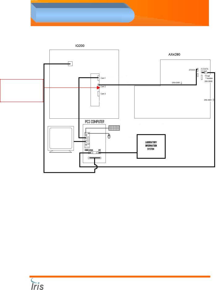
12.Make the cable connections between the
analyzers, and the computer according to the layout diagram.
NOTE: Do not use the grey cable provided with the Arkray kit, the pin out for this cable will not work due to incorrect pin positioning.
Iris Diagnostics, a Division of Iris International, Inc.
®
iQ 200 Sprint™ (2G) Automated Urine Microscopy Analyzer Service Manual 300-4949 Rev A 01/2005 2-11
2. Installation Procedures |
REMOVE jumpers on COM2 “Load” port before connecting directly to AX-4280
Iris Diagnostics, a Division of Iris International, Inc.
®
iQ 200 Sprint™ (2G) Automated Urine Microscopy Analyzer Service Manual 300-4949 Rev A 01/2005 2-12

2. Installation Procedures |
13.Power up the AX-4280 while holding the STOP button to access the Service mode.
a.Press -4280-.
b.Press 1: “User set up” then press 2: “User detail”.
c.Press ENTER until “Sampler” is displayed.
d.Press the “-” button until [LOWER] is displayed and then press
ENTER.
e.Save these settings when prompted.
f.Press ESC until the first menu is displayed.
g.Press 2: “Adjust”. Press 2: “Pulse & LED”. Press 1: “Pulse adjust”.
h.Press the “-“ button until [RACK] is displayed, then press ENTER.
i.Press the “-“ button until [Carry send] is displayed. Place a rack on the left side of the AX-4280 sampler in the area where the rack can be transferred to the iQ200 from the AX-4280 and press ENTER. Verify that the carry arm moves the rack to the iQ sampler and is positioned on the iQ 200 sampler fully.
j.If the distance needs to be adjusted, change the pulse number on the AX-4280 to the proper position. A larger number carries the rack further. Use the keypad to change the value.
Press 7 to increase the pulse number by 1 Press 4 to decrease the pulse number by 1 Press 9 to increase the pulse number by 10 Press 6 to decrease the pulse number by 10
k.Press MENU until the third menu is displayed.
l.Press 2: System Option. Press 1: Edit rack ID.
m.Enter the following rack ID information-
Rack numbers 1-11 |
Standard ID |
Rack number 12 |
Start |
Rack numbers 13-24 |
Standard ID |
Rack numbers 25-27 |
Standard ID |
Rack number 28 |
STAT/CTRL |
Rack numbers 29-30 |
PASS |
Rack number 31 |
NONE |
14.Save these settings when prompted.
15.Return to Standby mode.
Iris Diagnostics, a Division of Iris International, Inc.
®
iQ 200 Sprint™ (2G) Automated Urine Microscopy Analyzer Service Manual 300-4949 Rev A 01/2005 2-13
2. Installation Procedures |
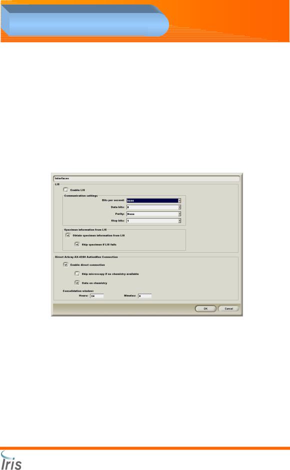
16.Load the AX Connectivity CD PN 700-3106 on the Analysis Processor.
17.From the Main Menu screen of the iQ, click on the Settings button.
18.Click on Interfaces.
19.Verify that the “Enable direct connection” checkbox with the AX4280 is selected.
Iris Diagnostics, a Division of Iris International, Inc.
®
iQ 200 Sprint™ (2G) Automated Urine Microscopy Analyzer Service Manual 300-4949 Rev A 01/2005 2-14
Loading...