


1234567890123456789012 |
123456789012345678901 |
123456789012345678901 |
123456789012345678901 |
123456789012345678901 |
123456789012345678901 |
123456789012345678901 |
123456789012345678901 |
123456789012345678901 |
123456789012345678901 |
123456789012345678901 |
123456789012345678901 |
123456789012345678901 |
123456789012345678901 |
123456789012345678901 |
123456789012345678901 |
123456789012345678901 |
123456789012345678901 |
123456789012345678901 |
123456789012345678901 |
123456789012345678901 |
123456789012345678901 |
123456789012345678901 |
123456789012345678901 |
123456789012345678901 |
n.v. |
123456789012345678901 |
123456789012345678901 |
123456789012345678901 |
123456789012345678901 |
123456789012345678901123456789012345678901123456789012345678901123456789012345678901 |
123456789012345678901 |
123456789012345678901 |
123456789012345678901 |
123456789012345678901 |
123456789012345678901 |
123456789012345678901 |
123456789012345678901 |
123456789012345678901 |
123456789012345678901 |
123456789012345678901 |
123456789012345678901 |
123456789012345678901 |
123456789012345678901 |
123456789012345678901 |
123456789012345678901 |
123456789012345678901 |
123456789012345678901 |
123456789012345678901 |
123456789012345678901 |
123456789012345678901 |
123456789012345678901 |
123456789012345678901 |
123456789012345678901 |
123456789012345678901LSG |
123456789012345678901 |
123456789012345678901 |
123456789012345678901 |
123456789012345678901 |
123456789012345678901 |
123456789012345678901 |
123456789012345678901- |
123456789012345678901 |
123456789012345678901 |
123456789012345678901 |
123456789012345678901 |
123456789012345678901 |
123456789012345678901 |
123456789012345678901 |
123456789012345678901 |
123456789012345678901 |
123456789012345678901 |
123456789012345678901 |
123456789012345678901 |
123456789012345678901 |
123456789012345678901 |
123456789012345678901 |
123456789012345678901 |
123456789012345678901 |
123456789012345678901 |
123456789012345678901 |
123456789012345678901 |
123456789012345678901 |
123456789012345678901 |
123456789012345678901 |
123456789012345678901 |
123456789012345678901 |
123456789012345678901 |
123456789012345678901 |
123456789012345678901 |
123456789012345678901 |
123456789012345678901 |
123456789012345678901 |
123456789012345678901 |
123456789012345678901 |
IPSO |
123456789012345678901123456789012345678901123456789012345678901123456789012345678901 |
123456789012345678901 |
123456789012345678901 |
123456789012345678901 |
123456789012345678901 |
123456789012345678901 |
123456789012345678901 |
123456789012345678901 |
123456789012345678901 |
123456789012345678901 |
123456789012345678901 |
123456789012345678901 |
1 |
1 |
1 |
1 |
1 |
1 |
1 |
1 |
1 |
1 |
1 |
1 |
1 |
1 |
1 |
123456789012345678901 |
123456789012345678901 |
123456789012345678901 |
123456789012345678901 |
123456789012345678901 |
123456789012345678901 |
123456789012345678901 |
123456789012345678901 |
123456789012345678901 |
123456789012345678901 |
123456789012345678901 |
Instruction manual
WE245
WE304
With electronical timer µ20
Technical specifications
Installation instructions
Operating instructions
Maintenance
Nieuwstraat 146 - B-8560 Wevelgem (Belgium)
Tel. 056/41 20 54 - Fax 056/41 86 74

Contents
1 |
Generalsafetyinstructions .............................................................. |
3 |
2 |
Technical data and dimensions ....................................................... |
4 |
|
Technical data ................................................................................ |
4 |
|
Dimensions ..................................................................................... |
5 |
3 |
Installation and connection ............................................................. |
6 |
|
Ground ............................................................................................ |
6 |
|
Anorching ....................................................................................... |
6 |
|
Water connection ............................................................................ |
6 |
|
Water drain ..................................................................................... |
7 |
|
Main power connection .................................................................... |
7 |
|
Automatic lubricator ........................................................................ |
8 |
|
Liquid soap connection ................................................................... |
9 |
|
Connection of a central operating panel for coinmachines ............... |
10 |
|
Steam connection ........................................................................... |
11 |
4 |
Operatinginstructions ..................................................................... |
12 |
|
Machine with start button ................................................................ |
12 |
|
Machine with coin or token operation............................................... |
21 |
5 |
Standardprograms .......................................................................... |
27 |
6 |
Technicalremarks............................................................................ |
28 |
|
Internal connection of the electrical heating .................................... |
28 |
|
Internal connections of the motor .................................................... |
28 |
|
Thermo-magnetic motor protection .................................................. |
29 |
|
Error messages .............................................................................. |
29 |
7 |
Maintenance of the machine ........................................................... |
31 |
Code:249/00183/00
02/01/01
Content
1
General safety instructions
Ignoring any of the safety instructions can cause serious personal injury and can also cause damage to the linen or the machine
Read the installation and instruction manual carefully before connecting the machine.
It is recommended that the machine be installed by qualified technicians.
The machine should be installed according to the installation instructions. (See chapter 4)
The machine should be grounded according to the instructions in order to eliminate the risk of electrocution.
Do not expose the machine to high humidity or extreme high or low temperatures.
Cut off all main water inlets, steam and electrical supplies at the end of each operating day.
Before starting repairs or maintenance, shut off all power and water supplies.
To prevent fire and explosion:
Keep the area around the machine free from inflammable or combustible products.
Do not put fabrics that are treated with inflammable products into the machine. These fabrics should be hand-washed or air-dried first.
Always carefully read and follow the instructions on the packing of detergents. Store these products out of the reach of children.
Always take into account the instructions on the labels of clothes. Never allow children to play in the surroundings of a machine.
Remark:
These instructions surely cannot prevent all risks of accidents. It is up to the user to act with the utmost precaution.
Do not hesitate to contact the dealer in case of a problem.
3

2
Technical data and dimensions
Technical data
|
|
|
WE 245 |
WE 304 |
Capacity |
(dry weight) |
1/11 |
23 kg |
28 kg |
|
|
|||
|
|
1/10 |
24,5 kg |
30,4 kg |
|
|
1/9 |
27,2 kg |
33,3 kg |
Cylinder |
|
Diameter |
850 mm |
850 mm |
|
|
|||
|
|
Depth |
432 mm |
537 mm |
|
|
Volume |
245 Lit. |
304 Lit. |
Cabinet |
|
Height |
1375 mm |
1375 mm |
|
|
|||
|
|
Width |
1060 mm |
1060 mm |
|
|
Depth |
980 mm |
1085 mm |
Front loading |
Diameter door opening |
395 mm |
395 mm |
|
|
|
|||
|
|
Door height - lower edge |
500 mm |
500 mm |
|
|
Door height - center |
690 mm |
690 mm |
Speed |
|
Wash |
|
40 tr/min. |
|
|
|
||
|
|
Distribution |
|
110 tr/min. |
|
|
Spin |
|
450 tr/min. |
G-force |
|
Spin |
|
84 |
|
|
|
||
Motors (3-phase) |
Wash 18p. 290 rpm |
370 W |
370 W |
|
|
|
|||
|
|
Distribution 18p. 290 rpm |
370 W |
370 W |
|
|
Spin 2p. 2850 rpm |
2200 W |
2200 W |
Drain |
|
Depend-O-Drain |
|
3" |
|
|
|
||
|
|
Option |
|
2" |
Water-inlet |
Hard, soft & hot water |
|
3/4" |
|
|
|
|
||
Steam connection |
Steam connection |
|
3/8" |
|
|
|
|
||
Heating |
|
Electric 220/380 V |
|
18 kW |
|
|
|
||
|
|
Electric 380 V |
|
18/24/30 kW |
|
|
Steam |
|
X |
|
|
Boiler fed |
|
X |
|
|
Boiler fed (with auxiliary heating) |
|
X |
Packing |
dimensions |
|
|
|
(H x W x D) |
1560x1160x1160 mm (WE245) |
1560x1160x1250 mm (WE304) |
||
Weight |
|
Net |
598 kg |
684 kg |
|
|
|||
|
|
Gross |
660 kg |
620 kg |
4

2
Dimensions
WE176
A. Hard water connection 3/4"
B. Warm water connection 3/4"
C. Soft water connection 3/4"
D. Electrical connection
E. Electrical connection clamps
F. Water drain
G. Steam connection
H. Ventilation soap dispenser
5
3
Installation and connection
Surface |
|
|
|
|
|
|
|
|
The machine must be securely fixed on a flat surface (metal base, concrete or |
|
|
|
|
solid ground). The anchoring is to be done on the provided places (A) in the base. |
|
|
|
|
(See Dimensions 2) |
|
|
|
|
The machine must be placed entirely level. For easy maintenance it is recom- |
|
|
|
|
mended to keep a minimal distance of 600 mm between the wall and the back |
|
|
|
|
of the machine. |
|
|
|
|
If several machines are placed next to each another, there should be a minimal |
|
|
|
|
distance of 30 mm between each machine. |
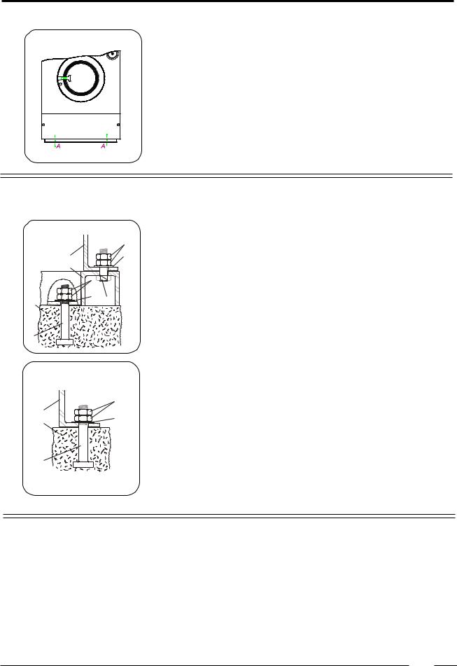
Anchoring |
|
|
|
|
|
|
|
|
On a metal base |
|
|
|
D |
The machines must be fixed on a metal base which is securely anchored on a |
|
E |
|
C |
concrete base. |
|
|
|
||
|
|
|
|
|
|
F |
|
|
A: Bolt M16 |
|
|
D |
|
B: Concrete base 70cm |
|
|
C |
|
C:Washer40x17x4 |
B |
|
G |
D: Nut M16 |
|
|
|
|||
|
|
|
|
|
|
|
|
|
E: Base of the machine |
|
|
|
|
F: Metal base |
A |
|
|
|
|
|
|
|
|
Directly on the ground |
|
|
|
|
The machine must be anchored directly on a concrete base. |
|
|
|
D |
|
E |
|
|
C |
A: Bolt M16 |
B |
|
|
B: Concrete base 70cm |
|
|
|
|
||
|
|
|
|
C:Washer40x17x4 |
|
|
|
|
D: Nut M16 |
A |
|
|
|
|
Water connection
The machine is delivered with hoses with 3/4" connections. These hoses fit the water inlet valves of the machine and the main water inlet taps. To ensure the optimal functioning of the water inlet valves, the water pressure on the inlet should be between 0,5 and 10 kg/cm² (7 and 145 psi). If the pressure is too low, the cycle time will increase considerably.
Incaseofboilerfedmachines,aminimumof hotwaterof90°Cshouldbeavailable. For the WE 245: 160l.
For the WE 304: 180l.
6
3
Water drain
The machine is equipped with a drain valve with 3" outer diameter (80 mm). This drain valve should be connected to the drain by means of the drain elbow which is delivered with the machine.
The diameter of the main drain should be adapted to the water flow and the number of machines. It should be sufficient to handle at least 160L/ min.permachine.
It is necessary to connect the main drain at least on one side to an open air-brake to allow ventilation.
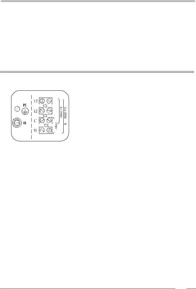
Main power connection
Remove the cover plate at the back of the machine. (See dimensions (E)). Connect the power cable to the connectors.
220V 3AC
220V 3 phase (3AC) should be connected to the connectors “L1,L2,L3”. The green/yellow grounding clamp has to be connected to the grounding wire “PE”.
380 V 3AC + N
Power of the breaker plugs:
380 V 3 phase (3AC + N) has to be connected to the connectors
“L1,L2,L3”, the blue neutral to the “N” connector.
The green/yellow grounding clamp has to be connected to the grounding wire “PE”.
After connection, check the spin direction. The cylinder must spin in the direction of the arrow, showed on the sticker on the door window (clockwise).
A wrong spin direction can damage the motor, and can also cause water to spurt from the soap dispenser.
In case of wrong spin direction: switch the terminal clamps of the motor circuit “R” and “S” of the connecting cable.
machine with steam heating or boiler fed machines without additional electrical heating
220V 3AC |
380V 3AC + N |
16 A |
16 A |
machine with electrical heating
Heating: |
220V3AC |
380V3AC+N |
18 kW |
50 A |
32 A |
21kW |
---- |
40 A |
24kW |
---- |
40 A |
30kW |
---- |
50 A |
7
3
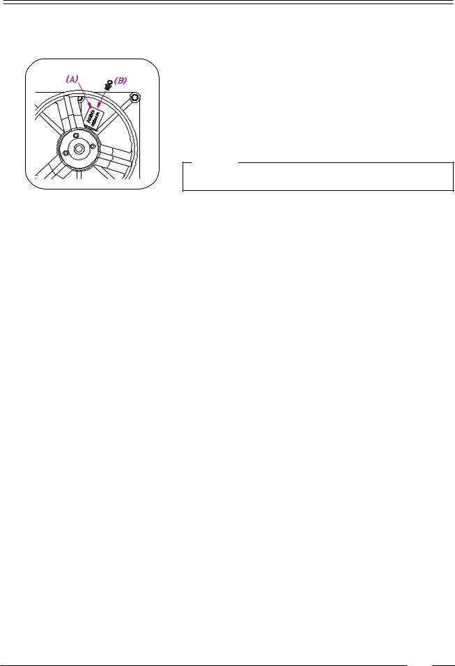
Automatic lubricator
The bearing house of the machine is equipped with a lubricating device (A) which automatically lubricates the bearing during one year. Upon delivery of the machine, this lubricator has not been brought into use. To this effect, please put on the matching screw (B) in the foreseen opening of the lubricator.
Remark
Ignoring this instruction will inevitably cause damage to the bearings!
8
3
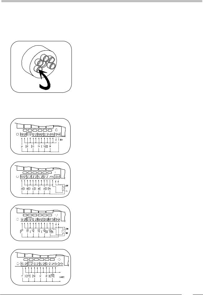
Liquid soap connection (option)
Connection of the liquid soap hoses
A rubber connection has been placed over the air break opening at the back of the machine. There are 5 holes in this rubber connection, through each of which a liquid soap hose can be driven (S1...S5). Press the hoses until they appear well inside the soap dispenser.
The central gap in the rubber connection remains and serves as air breaker.
Electrical connection of the liquid soap pumps
On machines equipped with a liquid soap connection, connect the wires directly on the print board next to the ground wire connection (option). Connect as indicated on the wiring diagram.
The two connectors on the right give a tension of 220V ~ (max. 4A) which can be applied to drive 220V ~ soap pumps. If more than 4A is required, an external tension will have to be used. 6 connections have been provided, of which one (S6) can be used to drive a waterproofing pump (e.g. for rain coats, etc.).
The 220V can be transformed to other values to drive other type soap pumps.
Example: pumps 24V ~.
Also, pumps with different operating tension can be combined.
Example: 5 pumps 220V ~ and 1 pump 24V ~.
With an external tension 24V DC
9
3
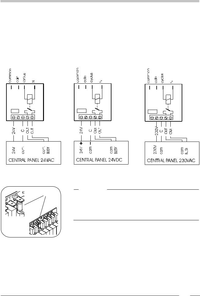
Connection of a central operating panel for coinmachines (option)
At the backside above the main connectors, you find a printboard, to which the central operating panel for coinmachines can be connected.
The right connectors form a potential free output contact as a result of which the operating
panel detects when the machine is activated or not.
The left connectors receive the signal, by means of which a machine is chosen through the operating panel.
There are 3 different variations possible according to the output voltage of the operating panel.
A |
Remark : |
|
If a machine is equipped with this kind of printboard or if a printboard |
||
|
||
|
has been built in, the resistance of the cycle contact (A) may no longer |
|
|
be present on the main printboard. |
|
|
When this resistance is present, it has to be cut out of the main |
|
|
printboard. |
10
 Loading...