

Page 1

Page 2
Your new International Harvester rotary mower is designed to meet
today's exacting operating requirements. The ease of operation and
ability to adjust to field conditions lighten your work and shorten your
hours on the job.
You are urged to consult your International Harvester dealer con-
cerning unusual field conditions or special applications. Let the
experience of your dealer and the organization associated with him
serve you.
Be sure to read the instructions for Adjusting and Operating in this
manual. Check each item referred to and acquaint yourself with the
adjustments required to obtain efficient operation and maximum
trouble-free performance. Remember, an implement which is properly lubricated and adjusted saves time, labor, and fuel.
After the mowing season, thoroughly clean your implement and
inspect it. Preventive maintenance pays dividends. Your dealer has
original-equipment parts which assure proper fit and best performance.
He is able to recondition your equipment to a like new condition.
When in need of parts for the mower, always specify the mower
model and serial number, and the model of IH tractor, Fast-Hitch
or standard drawbar. The mower serial number is stamped on a
name plate riveted to the top of the mower platform on the left side.
MODEL NO.
SERIAL NO.
Page 3

Page 4
Page 5

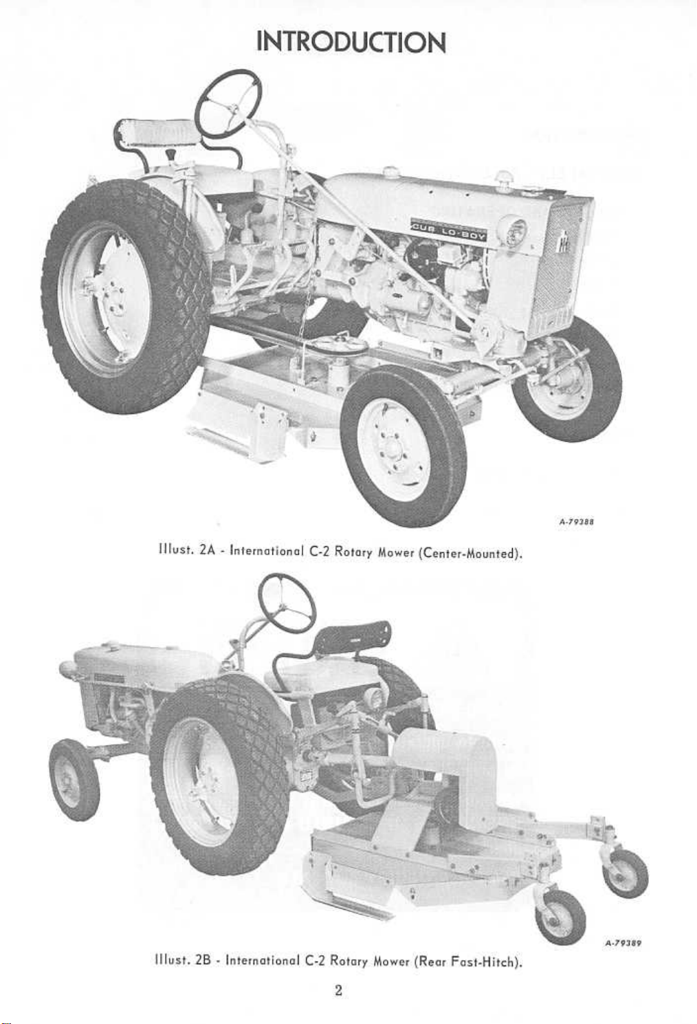
INTRODUCTION
The International C -2 Rotary Mower is
designed for use on the International @ Cub
Lo-Boy@, McCormick@ Farmall Cub@
and International 140 Tractor.
The mower is available as a tractor
center-mounted or as a rear Fast-Hitch
machine.
Tractor mounting kits are necessary for
mounting the mower on these tractors. The
tractor must be equipped with Touch-Con-
trol hydraulics and power take-off. For
mounting the mower on Farmall Cub or
International 140 Tractors with Fast-Hitch,
a belt pulley attachment (less pulley wheel)
is required.
Features and general specifications:
Cutting width: 42-in.
Cutting height: 1 to 8 inches
Heavy duty V -belt drive
Non-wrap spindle
2 spring steel reversible blades
2 high speed tapered roller bearings
Overrunning clutch
Adjustable runners
Adjustable safety shields
Weight (approximately): center-mount
280 pounds, rear-mount 400 pounds
A leaf mulcher attachment (optional)
mulches the leaves and distribu,tes them
evenly over the lawn, thereby eliminating
raking.
The illustrations in this manual are num-
bered to correspond with pages on which
they appear; for example, Illusts. 8A and 8B
are on page 8.
This symbol is used to call your attention to instructions
concerning your personol safety. Be sure to observe and
follow these instructions.
A CAREFUL OPERATOR IS THE BEST INSUR-
ANCE AGAINST AN ACCIDENT.
Do not operate at above factory recom-
mended speeds.
See that all safety shields are in place
and properly secured before starting to
operate the mower.
Make sure that everyone is in the clear
before starting the mower.
Throttle down the tractor to reduce
mower speed before disengaging the power
Disengage the power take-off be-
fore leaving the tractor seat.
Do not attempt to lubricate or adjust the
mower while it is running.
Maintain minimum ground speed when
operating on rough terrain or near ditches.
Take all precautions to be sure that
children cannot start the tractor when it is
left unattended.
Never permit anyone except the operatorto
ride on the tractor.
take-off.
3
Page 6

GENERAL
BELT ADJUSTMENT
Before using, carefully lubricate the
mower. Check all bolts for tightness and
see that all cotter pins are spread.
Check the tightness of the drive belt
with the platform lowered to cutting position.
The belt should be re-tightened after five
hours of normal use, and periodically there-
after.
Caution! Di sengage the tractor power take-off
and stop the engine before working on the
mower.
CUTTING HEIGHT
Before operating the mower, set the
adjustable lever stops on the Touch-Control
quadrant so that the mower can be loweredto
the desired cutting height.
Adjust platform runners as required.
Center-Mounted Mower
Always adjust the belt tension when the
platform is in a down position.
International Cub Lo-Boy or Farmall Cut Tractors
without Fast-Hitch: When tightening the belt,
the rear idlers should be positioned approx-
imately the same distance from the top of
the slot. See Illusts. 6A and 8A.
Farmall Cub and International 140 Tractors with
Fast-Hitch: When adjusting the belt, the flat
idler must be positioned properly, other-
wise the belt may wear excessively. See "A"
in Illusts. lOA and 12A.
After considerable use, the drive belt
may have more slack than can be taken up
by the usual idler adjustment; this will
necessitate moving the platform forward
by relocating the pivot position of the plat-
form angles.
Rear Fast-Hitch Mower
ADJUSTMENT
The tail wheel arm can be adjusted to a
high or low position. Raise the mower hydraulically then loosen bolt at "A". Remove
other bolt in tail wheel arm and secure in
holes at "B" for low cut or in holes 'ICY' for
high cut. Retighten bolt "A". See II lust. 14A.
Adjust the guide wheel at desired height
and replace pin.
Never tighten the belts when the platform is in a
raised position.
Position the belt guides on both sides of
the clutch sheave to prevent belt side play.
Rear Fast-Hitch Mower
Proper belt tension may be obtained by
utilizing drive sheave adjustment screw
"D" and the slotted holes "E" in the mounting bracket. See Illust. 14A.
4
Page 7

ADJUSTING AND OPERATING
STARTING AND STOPPING THE MOWER
Throttle down the engine before engaging
or disengaging the power take-off. This will
reduce the wear on the main drive belt as
well as the tractor clutch. Throttling down
when disengaging the power take -off causes
the mower blade to stop rotating more
quickly.
BLADE CARE
Caution! Never look under the mower while
the blades are in motion.
If the mower is being used in particularily
rough terrain, a frequent check of the cutting
blades is advisable. The blades are reversible and may be sharpened. However, when
they show excessive wear, install new blades
to insure correct balance and maximum efficiency. Always install new blades in pairs.
If this is not done, vibration may occur.
CLEANING
Caution! Stop the tractor motor before attempt -
ing to clean or work on the mower.
Clean the underside of the mower at the
end of the mowing season or when the
buildup of cut material on the underside is
noticed.
LUBRICA TION
Always lubricate the mower thoroughly
before taking it to the field.
When using a pressure-lubricating gun,
be sure all of the fittings are free from dirt
and paint, so the lubricant is certain to
enter the bearing.
The spindle is equipped with two highspeed tapered roller bearings, and should
be greased once during an eight-hour mowing
operation. Use IH 251H EP grease or equivalent No.2 multi-purpose lithium grease.
Lubricate the overruning clutch once a
week with IH 251H EP grease or equivalent
No.2 multi-purpose lithium grease. The
clutch should be disassembled at least twice
during the mowing season to check the pins
and springs. When assembling, the pin
holes should be filled with the grease.
The idlers are equipped with high-speed
ball bearings and should be lubricated with
a medium grade motor oil. Avoid excessive
oiling of the idlers. Keep the drive belt free
of oil.
All moving parts, such as pivot points,
should have a few drops of oil occasionally.
Proper lubrication is the best method of
keeping operational expense at a minimum.
5
Page 8

Remove all wires. Sort out all hardware
by sizes and types in a convenient and orderly manner.
Lubricate all bearings and moving parts
as you proceed, and see that they work
freely.
Bolts must be used in the holes in which
they are found, or in the parts to which
they are attached, unless otherwise shown.
Wherever the terms "right" and "left"
are used, it should be understood to mean
from a position behind and facing the ma-
chine.
If the tractor rear tires are oversize,
the wheels may need to be extended before
mounting to prevent interference.
INTERNATIONAL CUB La-BOY TRACTOR
1. Attach the idler bracket assembly to
the tractor differential housing. When
securing bracket, replace the tractor bolts
with the four 3/8 x 1-3/4-inch hex. head cap
screws furnished in the kit. Position the
splined hub on the tractor power take-off
shaft, then place the drive sheave around it.
Secure with the three 1/4 x 1-1/8-inch hex.
head cap screws. Screw the shoulder bolts
into the idler bracket. See Illust. 6A.
2. Attach the left and right pivot brackets
to the tractor axle casting, using two 5/8 x
1-1/2-inch hex. head cap screws and lock
washers on each bracket. See Illust. 6A.
Illust.6A
6
Page 9

SETTING UP
INTERNATIONAL CUB LO-BOY TRACTOR
Illust.7A
3. Attach the lift chain mounting angle to
the platform with one 1/2 x 1-1/4-inch hex.
head cap screw, flat washer, lock washer,
and nut. See Illust. 7A.
4. Position the platform assembly under
the tractor. Attach the lift angles to the
platform, using eight 1/2 x 1-1/4-inch hex.
head cap screws, flat washers, lock
washers, and nuts. Note: The leg of the
angle that bolts to the platform must extend
inward toward the spindle. Do not tighten the
nuts at this time. See Illust. 7A.
5. Attach the lift chain arm to the top
hole in the tractor mounting pad with one
5/8 x l-inch hex. head cap screw, pivot
bushing, flat washer, and lock washer.
Secure one end of the lift chain pivot strap
to the tractor right rockshaft arm, using
one 5/8 x 1-3/4-inch hex. head cap screw,
pivot bushing, flat washer, lock washer,
and nut. Secure the other end of the lift
chain pivot strap to the lift chain arm,
using one 5/8 x 1-1/2-inch hex. head cap
screw, pivot bushing, flat washer, lock
washer, and nut. Note: The three pivot
bushings must be properly inserted into the
linkages to permit them to have a free
.pivoting action. See Illust. 7A.
Attach the chain to the lift chain arm and
to the angles on the platform.
6. Assemble the lift angles to the rear
pivot brackets. Secure each with one 1/2 x
1-1/2-inch hex. head cap screw, pivot
bushing, flat washer, lock washer, and nut.
Note: Pivot bushings must be placed in the
large holes in brackets to allow the proper
pivoting action. See Illust. 6A. When installing a new mower, the fourth hole from the
rear of the angles should be used, unless the
rear tires are oversize.
7. Go over the entire unit and tighten all
cap screws previously left loose. Reposition
platform runners, using top two holes.
8. Install the drive belt around the idler
pulleys, rear drive sheave and the platform
drive sheave. See Illusts. 6A and 7A. To
secure the correct belt tension, place the
platform on ground level. Adjust the idlers
downward until the proper belt tension is
obtained. When adjusting the drive belt tension, the
drive belt should be tight only when the mower platform
is down and in mowing position. This is necessary
to prevent downward pressure on the tractor
power take-off bearing. When the platform
is raised and in transport position, there
should be no tension on the drive belt.
9. To mount the belt guides, remove the
left and right rear bolts and lock washers
from the platform spindle housing. Install
the belt between the guide fork. Retighten
the cap screws securely. See Illust. 7A.
10. Position the holes in the rear belt
guard over the belt guard mounting lugs.
Secure with two 3/8-inch nuts and lockwashers.
Check "Lubrication" instructions before
operating .
7
Page 10

FARMALL CUB TRACTOR
(Without Fast-Hitch)
Illust.8A
SETTING UP
Note: For ease in mounting, position the
drawbar to the lowest adjustment with the
adjusting bolts extending toward the wheels.
1. Mount the idler mounting bracket inside the drawbar, using the four 5/8 x 1-1/2
inch hex. head cap screws and lock washers.
See Illust. 8A. If the tractor is not equipped
with a drawbar, use the two 3/8-inch spacer
plates furnished in the kit.
2. Attach the two pivot plates to the in-
side of the mounting lugs on the rear
mounting bracket. Place a pivot bushing
in the holes of the mounting lugs and secure
with 1/2 x 1-3/4-inch bolts, flat washers,
lock washers, and nuts.
3. Position the splined hub on the tractor
power take -off shaft far enough so that
approximately 1/4-inch of shaft is exposed
at the end. Place the drive sheave around
it and secure with three 1/4 x 1-1/8-inch
hex. head cap screws. See Illust. 8A.
Illust.88
4. Position the platform assembly under
the tractor. Attach the lift angles to the
platform with eight 1/2 x 1-1/4-inch hex.
head cap screws, flat washers, and nuts.
Note: The leg of the angle that bolts to the
platform must extend inward toward the
spindle. Do not tighten the nuts ot this time. See
I I lust. 88.
5. Secure the lift angles to the inside of
the pivot plates, using four 1/2 x 1-1/4-inch
hex. head cap screws, lock washers, and
nuts. When installing a new mower, use the
two front mounting holes of each angle. See
Illust. 8A .
6. Tighten the platform bolts previously
left loose.
8
Page 11

FARMALL CUB TRACTOR
(Without Fast-Hitch) -Continued
SEmNG UP
7. Attach the lift chain arm to the tractor
right rocks haft arm, using two 5/8 x 1-3/4
inch hex. head cap screws, lock washers,
and nuts. Attach the lift chain to this arm
and to the lift angle, using a 3/8 x 1 inch
hex. head cap screw, flat washers, lock
washer, and nut. See II lust. 86.
8. Install the drive belt around the idler
pulleys, rear drive sheave, and platform
drive sheave. See Illusts. 8A and 86. Note: The
belt extends from the right hand idler to the
right hand side of the platform drive sheave.
Note: To secure the correct belt tension,
place the platform on ground level. Then
loosen the nuts on the idler bolts and adjustthe
idlers "A" (1IIust. SA) equally downward
until the desired belt tension is obtained.
9. To mount the belt guides, remove the
left and right rear cap screws, and lock
washers from the platform spindle housing.
Install the belt between the guide fork. Retighten the cap screws securely. See Illust. 86.
10. Attach the rear belt. guard by insertingthe
prongs at the base of the guard into the
two holes in the top of the rear mountingbracket.
The hole in the mounting strap
should now be positioned over the tapped hole
in the tractor power take-off housing. Secure
with a 1/2 x 3/4 inch hex. head cap screwand
lock washer.
Check "Lubrication" instructions beforeoperating.
~
9
INTERNATIONAL
HARVESTER
Page 12

SETTING UP
FARMALL CUB TRACTOR
(With Fast-Hitch)
Note: The pull bar on the hitch must be
moved to the furthest right hand setting.
1. Attach the rear mounting bracket as-
sembly on the inside of the Fast-Hitch side
casting. The two spacer plates provided in
the kit must be positioned between the Fast-
Hitch casting and the mounting bracket to
allow proper clearance. Secure the assembly
with 5/8 x 2-1/2 inch hex. head cap screws
and lock washers. See Illust. lOA.
2. Attach the two pivot bars to the inside
of the plates extending downward on the rear
mounting bracket. Use two 1/2 x 1-3/4 inch
hex. head cap screws, flat washers, lock
washers, and nuts. Note: Make sure that the
1/2 inch thick pivot bushings are properly
positioned in the plates. See Illust. lOA.
lOA
3. The tractor requires the use of a belt
pulley gear box (not furnished with the mower)
and is to be mounted next. Refer to the
tractor Operator's Manual for instructions.
See Illust. lOA.
4. Insert the two 1-1/32 x 1-1/2 inch x
11 ga. washers over the belt pulley drive
shaft. Install the splined hub on the shaft,
then position the drive sheave around the
splined hub and secure with three 1/4 x 1-1/8
inch hex. head cap screws. See 'Ilust. lOA.
5. Position the platform assembly under
the tractor. Attach the lift angles to the
platform with eight 1/2 x 1-1/4 inch hex.
head cap screws, flat washers, lock washers,
and nuts. Note: The leg of the angle that bolts
to the platform must extend inward toward
the spindle. Do not tighten the nuts at this time.
See Illust. llA.
6. Secure the lift angles to the rear pivot
bars with four 1/2 x 1-1/4 inch hex. head
cap screws, lock washers, and nuts. When
installing a new mower, use the second and
third holes from the rear of the angle. See
1!lust. lOA.
7. Tighten the platform cap screws pre-
viously left loose. Reposition platform run-
ners in top two holes.
8. Attach the lift chain arm to the inside
of the tractor right rockshaft arm, using two
5/8 x 1-3/4 inch hex. head cap screws, lock
washers, and nuts. Attach the lift chain to
this arm and to each lift angle, using a 3/8
x 1 inch hex. head cap screw, flat washer,
lock washer, and nut. See Illust. llA.
9. Install the drive belt around the idlers,
platform drive sheave, and rear drive sheave.
Note: The belt extends from the flat idler to
the right hand side of the platform drive
sheave. See Illusts. lOA and llA.
Illust.
10
Page 13

FARMALL CUB TRACTOR
(With Fast-Hitch) -Continued
SETTING UP
Il/ust. 118
Illust. llA
10. The flat idler swivel bracket must be
set so that the belt will travel in the center
of the idler. This is extremely important to
ensure belt life. The flat idler "A" (1IIust. lOA)
should be positioned in a direct line with the
rear drive sheave and in line with the right
hand side of the platform spindle sheave.
Adjust the V -idler pulley "B" downward until
the belt is snug. This must be accomplished
with the platform in down position. Start the
tractor and idle slowly with the power takeoff engaged. If the belt rides to one side of
the flat idler, stop the tractor, loosen the
flat idler swivel bracket mounting screws
and readjust the bracket. Retighten the belts
and start the tractor again. Repeat this procedure until the belt is riding in the center
of the idler. The flat idler swivel bracket
need only be adjusted at the initial mounting
of the mower.
For correct belt tension the platform must be in a
down position. Adjust the V -idler downward
until belt is stretched tight.
11. To mount the belt guides, remove the
left and right rear cap screws and lock
washers from the platform spindle housing.
Install the belt between the guide fork. Re-
tighten the cap screws securely. See Illust. llA.
12. Secure the rear belt guard by positioning it around the rear drive sheave and idlers.
The top of the guard is attached by bolting
the angle clip to the tractor taillight bracket,
then securing the guard to this clip with a
1/4 x 3/4 inch hex. head cap screw, lock
washer, and nut. The lower arm on the guard
is attached to the idler mounting bracket with
a 1/4 x 1 inch hex. head cap screw, flat
washer, and nut. See Illust. 11B.
Check "Lubrication" instructions before
operating.
11
Page 14

INTERNATIONAL 140 TRACTOR
SETTING UP
12A
Note: Tractors with Fast-Hitch: The pull bar
on the hitch must be moved to the furthest
left hand setting.
1. Tractors with Fast-Hitch: Attach the rear
mounting bracket assembly to the inside of
the tractor Fast-Hitch side casting, using
four 3/4 x 2-3/4" hex. head cap screws and
lock washers.
Tractors without Fast-Hitch or drawbar: Attach the
rear mounting bracket assembly to the trac-
tor rear axle housing by placing one 1/2"
spacer plate and one 3/8" spacer furnished
on each housing to properly position the
bracket. Secure with the four 3/4 x 2-3/4"
hex. head cap screws and lock washers.
Tractors with standard drawbar: Attach the rear
mounting bracket assembly to the tractor
rear axle housing with the 3/8" spacer plates
furnished. Secure with the four 3/4 x 2-3/4"
hex. head cap screws and lock washers.
126
2. Attach the pivot brackets to the inside
of the legs extending downward on the rear
mounting bracket, using two 1/2 x 1-3/4 inch
hex. head cap screws, flat washers, lock
washers, and nuts. See Illust. 12A. Note: Make
sure that the pivot bushings are properly inserted in the 3/4 inch diameter holes.
3. The tractor requires the use of a belt
pulley (not furnished with the mower) and is
to be mounted next. Refer to the tractor
Operator's Manual for instructions.
4. Place two 1-5/32 x 1-3/4 x 11 ga.
washers on the belt pulley drive shaft. Install
the splined hub on the drive shaft, then position the drive sheave around the splined hub
and secure with three 1/4 x 1-7/8" hex. head
cap screws. See Illust. 12A.
Illust.
Illust.
12
Page 15

140 TRACTOR
UP
5. Attach the flat idler swivel bracket
assembly to the rear mounting bracket, usingtwo
1/2 x 1-1/2" hex. head cap screws, flat
washers, lock washers, and nuts. Do not tighten
the cap screws at this time. See II lust. 12A.
6. Position the platform assembly under
the tractor. Attach the lift angles to the plat-
form with eight 1/2 x 1-1/4" hex. head capscrews,
flat washers, lock washers, and
nuts. The leg of the angle that bolts to the
platform must extend inward toward the
spindle. Do not tighten the nuts at this time. See
II lust. 126.
7. Secure the lift angles to the pivot
brackets as shown in Illust. 12A with four 1/2
x 1-1/4" cap screws, lock washers, and nuts.
When installing a new mower, the second and
third holes from the rear of each angle
should be used.
8. Tighten the platform bolts previously
washers from the platform spindle housing.
left loose.
9. Attach the lift chain arm to the tractor
right rock shaft arm and to each lift angle,using
a 3/8 x 1 inch hex. head cap screw,
flat washers, lock washers. and nuts. See
Illust .126.
10. Install the drive belt around the idlers,
platform drive sheave, and rear drive sheave.
Note: The belt extends from the flat idler tothe
right hand side of the platform drivesheave.
See Illusts. 12A and 12B.
11. The flat idler swivel bracket must be
set so that the belt will travel in the center
of the idler. This is extremely important to
ensure belt life. The flat idler II A" (1IIust. 12A)
ing it around the drive sheave and idlers. Thelong
tractor belt pulley gear box with a 3/8 x 3/4"hex.
lower mounting clip is bolted to the rear
should be positioned in a direct line with the
rear drive sheave and in line with the right
hand side of the platform spindle sheave.
Adjust the V -idler pulley "B" downward until
the belt is snug. This must be accomplished
with the platform in down position. Start the
tractor and idle slowly with the power takeoff engaged. If the belt rides to one side of
the flat idler, stop the tractor, loosen the
flat idler swivel bracket mounting screws
and readjust the bracket. Retighten the bolts
and start the tractor again. Repeat this procedure until the belt is riding in the center of
the idler. The flat idler swivel bracket need
only be adjusted at the initial mounting of the
mower. For correct belt tension the platform must be
in a down position. Adjust V -idler downward
until the belt is stretched tight.
12. To mount the belt guides, remove the
left and right rear cap screws and lock
Install with the belt between the guide fork.
Retighten the cap screws securely. See Illust.128.
13. Secure the rear belt guard by positionarm on the guard extends out to the lefthand
side and is fastened to the back of the
head cap screw and flat washer. The
mounting bracket, using a 3/8 x 1 "hex. head
cap screw, flat washer, lock washer, andnut.
Check "Lubrication" instructions beforeoperating.
SETTING
INTERNATIONAL
13
Page 16

SETTING UP
REAR FAST-HITCH MOWER
(Used only on International Cub Lo-Boy and Farmall Cub
Fast-Hitch Tractors)
1. Attach the lift angles to the platform,
using four 1/2 x 1-1/4"hex. head cap screws,
flat washers, lock washers, and nuts. Main-
tain a distance between the angles of 22 -inches,
outside to outside, with each angle held 11-
inches from the center of the platform. See
Illust. 14A.
2. Attach the spindle and idler mounting
bracket assembly to the left platform lift
angle, using two 1/2 x 1-1/4" hex. head cap
screws, lock washers, and nuts.
3. Attach the right hand plate assembly to
the right platform lift angle, using two 1/2
x 1-1/2" hex. head cap screws, lock washers,
and nuts.
4. Position the Fe.st-Hitch bar between
the spindle mounting bracket and the right
hand plate assembly. Secure with two 5/8 x
2-3/4" hex. head cap screws, lock washers,
and nuts.
5. Attach the transfer spindle assembly
to the spindle and idler mounting bracket,
using four 1/2 x 1 II hex. head cap screws,
lock washers, and nuts.
6. Attach the drive sheave and hub to the
transfer spindle assembly and secure with
three 1/4 x 1-1/8" hex. head cap screws and
lock washers.
7. Position the drive belt around the plat-
form clutch sheave, idlers and transfer
sheave. See Illust. 14A. Proper belt tension
may be obtained by utilzing the drive sheave
adjustment screw and the slotted holes in the
mounting bracket.
8. Attach the bored end of the universal
to the spindle shaft and secure with one 3/8
x 2-1/2" hex. head cap screw and hex. head
lock nut. See Hlust. 14A.
9. Mount the belt guard on the spindle
mounting bracket with two 5/16 x 3/4" hex.
head cap screws and lock washers.
Illust. 14A
14
Page 17

SETTING UP
10. Mount the tail wheel arm assemblies
to the platform lift angles, using two 1/2 x
1-1/2" hex. head cap screw, lock washers,
and nuts for each arm.
11. Mount the wheel and wheel arm assem-
blies to the tail wheel arms with 1/2 x 1-3/4
inch clevis pin, flat washer, and 5/32 x 1
inch cotter pin.
This completes the assembly; the mower
is now ready to be mounted to the tractor.
12. Farmall Cub Tractor: Reverse the diagonal
link to allow mounting of the universal drive.
See Illust. 15A.
International Cub Lo-Boy Tractor: Remove the
pull bar support from the Fast-Hitch and
replace with the support bar and bushing as-
sembly furnished with the mower. See Illust.
14A.
13. Mount the mower to the tractor by
backing the tractor to the mower so that the
prong slips into the hitch socket.
LEAF MULCHER
Remove the front, rear and side platformshields.
Set the runners in the center height posi-
tion.
Remove the rear bolts which hold the lift
angles to the platform.
Illust. 15A
14. Complete mounting of the mower by
attaching the splined end of the universal to
the tractor power take-off shaft with a 3/16
x 2-1/2 inch cotter pin.
Check "Lubrication" instructions before
operating.
4. Attach the front shield to the front of
the platform with hardware proviously re-
moved.
Go over entire unit and tighten all bolts.
Note: For the leaf mulcher to function at
its best, the rear of the platform should be
set in its lowest position.
1. Position the leaf basket (II lust. 15B}
under the platform and insert the two 1/2 x
1-1/2 inch bolts up through the mounting
plate and att-ach loosely to the platform top.
2. Bolt the two flat mounting clips to the
side of the platform with hardware previ-
ously removed.
3. Secure the leaf basket to the clips with
the 3/8 x 1 inch bolts, flat washers, lockwashers,
and nuts provided.
15
Illust.
15B
Page 18

Possible Cause
Possible Remedy
VIBRA TION
Loose mounting bolts. Blades out of balance.
Bent spindle shaft
Loose belts. Worn blades
Lack of lubrication.
Platform not adjusted level.
Mower set too low.
Check all bolts and nuts for tightness.
Inspect blades for damage. Remove and
sharpen evenly, or replace with new blades.
See page 5.
Replace shaft.
UNCUT STRIPS
Adjust belt tension. See page 4.
Sharpen or replace. See page 5.
TIGHT SPINDLES
Lubricate; if spindle still continues to be
tight, replace spindle components or complete spindle.
SCALPING
Center-mounted mower: Check mounting of plat-
form at rear of tractor. Adjust platform
runners.
Rear-mounted mower: Adjust guide wheels and/or
Touch-Control settings to level platform.
Adjust platform runners.
Center-mounted mower: Check mounting of plat-
form at rear of tractor. Adjust platform
runners. Check Touch-Control setting.
Rear-mounted mower: Adjust guide wheels or
Touch-Control settings to raise platform.
Adjust platform runners.
BELT JUMPING OFF PULLEY
Loose belt. Drive belt should be secured snug in the
groove of the platform pulley. Belt guides,
when in proper position, should prevent
belt from coming off.
PLATFORM SIDE SWAY
Platform not fully lowered to cutting
position
Center-mounted mower: Check setting of Touch-
Control stop.
Rear-mounted mower: Check tail wheel arms to
see that they are properly positioned.
16
Page 19

Page 20

 Loading...