

Page 1
Wireless 802.11n
Broadband Router 523967
User Manual
INT-523967-UM-0208-1
Page 2

Federal Communication Commission
Interference Statement
FCC Part 15
This equipment has been tested and found to comply with the limits for a Class B
digital device, pursuant to Part 15 of FCC Rules. These limits are designed to provide
reasonable protection against harmful interference in a residential installation. This
equipment generates, uses, and can radiate radio frequency energy and, if not installed
and used in accordance with the instructions, may cause harmful interference to radio
communications. However, there is no guarantee that interference will not occur in a
particular installation. If this equipment does cause harmful interference to radio or
television reception, which can be determined by turning the equipment off and on,
the user is encouraged to try to correct the interference by one or more of the
following measures:
1. Reorient or relocate the receiving antenna.
2. Increase the separation between the equipment and receiver.
3. Connect the equipment into an outlet on a circuit different from that to
which the receiver is connected.
4. Consult the dealer or an experienced radio technician for help.
FCC Caution
This equipment must be installed and operated in accordance with provided
instructions and a minimum 20 cm spacing must be provided between computer
mounted antenna and person's body (excluding extremities of hands, wrist and feet)
during wireless modes of operation.
This device complies with Part 15 of the FCC Rules. Operation is subject to the
following two conditions: (1) this device may not cause harmful interference, and (2)
this device must accept any interference received, including interference that may
cause undesired operation.
Page 3

Any changes or modifications not expressly approved by the party responsible for
compliance could void the authority to operate equipment.
Federal Communication Commission (FCC) Radiation Exposure
Statement
This equipment complies with FCC radiation exposure set forth for an uncontrolled
environment. In order to avoid the possibility of exceeding the FCC radio frequency
exposure limits, human proximity to the antenna shall not be less than 20cm (8 inches)
during normal operation.
The antenna(s) used for this transmitter must not be co-located or operating in
conjunction with any other antenna or transmitter.
Page 4

R&TTE Compliance Statement
This equipment complies with all the requirements of DIRECTIVE 1999/5/EC OF
THE EUROPEAN PARLIAMENT AND THE COUNCIL of March 9, 1999 on radio
equipment and telecommunication terminal Equipment and the mutual recognition of
their conformity (R&TTE).
The R&TTE Directive repeals and replaces in the directive 98/13/EEC
(Telecommunications Terminal Equipment and Satellite Earth Station Equipment) As
of April 8, 2000.
Safety
This equipment is designed with the utmost care for the safety of those who install
and use it. However, special attention must be paid to the dangers of electric shock
and static electricity when working with electrical equipment. All guidelines of this
and of the computer manufacture must therefore be allowed at all times to ensure the
safe use of the equipment.
EU Countries Intended for Use
The ETSI version of this device is intended for home and office use in Austria,
Belgium, Denmark, Finland, France, Germany, Greece, Ireland, Italy, Luxembourg,
the Netherlands, Portugal, Spain, Sweden, and the United Kingdom.
The ETSI version of this device is also authorized for use in EFTA member states:
Iceland, Liechtenstein, Norway, and Switzerland.
EU Countries Not intended for use
None.
Page 5

Table of Contents
CHAPTER I: PRODUCT INFORMATION
1-1 Introduction and safety information
1-2 Safety Information
1-3 System Requirements
1-4 Package Contents
1-5 Wireless broadband router hardware description
CHAPTER II: SYSTEM AND NETWORK SETUP
2-1 Connecting the Wireless Broadband Router
2-2 Connecting to the Wireless Broadband Router
2-2-1 Windows 95/98/Me IP address setup
2-2-2 Windows 2000 IP address setup
2-2-3 Windows XP IP address setup
2-2-4 Windows Vista IP address setup
2-2-5 Router IP address lookup
2-3 Using 'Quick Setup'
2-3-1 Setup procedure for 'Cable Modem'
2-3-2 Setup procedure for 'Fixed-IP xDSL'
2-3-3 Setup procedure for 'PPPoE xDSL'
2-3-4 Setup procedure for 'PPTP xDSL'
2-3-5 Setup procedure for 'L2TP xDSL'
2-3-6 Setup procedure for 'Telstra Big Pond'
2-4 Basic Setup
2-4-1 Time zone and time auto-synchronization
2-4-2 Change management password
Page 6

2-4-3 Remote Management
2-5 Setup Internet Connection (WAN Setup)
2-5-1 Setup procedure for 'Dynamic IP'
2-5-2 Setup procedure for 'Static IP'
2-5-3 Setup procedure for 'PPPoE'
2-5-4 Setup procedure for 'PPTP'
2-5-5 Setup procedure for 'L2TP'
2-5-6 Setup procedure for 'Telstra Big Pond'
2-5-7 Setup procedure for 'DNS'
2-5-7 Setup procedure for 'DDNS'
2-6 Wired LAN Configuration
2-6-1 LAN IP section
2-6-2 DHCP Server
2-6-3 Static DHCP Leases Table
2-7 Wireless LAN Configuration
2-7-1 Basic Wireless Settings
2-7-1-1 Setup procedure for 'AP'
2-7-2 Advanced Wireless Settings
2-7-3 Wireless Security
2-7-3-1 Disable wireless security
2-7-3-2 WEP - Wired Equivalent Privacy
2-7-3-3 Wi-Fi Protected Access (WPA)
2-7-3-4 WPA RADIUS
2-7-4 Wireless Access Control
2-7-5 Wi-Fi Protected Setup (WPS)
2-7-6 Security Tips for Wireless Networks
CHAPTER III: ADVANCED FUNCTIONS
3-1 Quality of Service (QoS)
3-1-1 Basic QoS Settings
3-1-2 Add a new QoS rule
3-2 Network Address Translation (NAT)
Page 7

3-2-1 Basic NAT Settings (Enable or disable NAT function)
3-2-2 Port Forwarding
3-2-3 Virtual Server
3-2-4 Port Mapping for Special Applications
3-2-5 UPnP Setting
3-2-6 ALG Settings
3-3 Firewall
3-3-1 Access Control
3-3-1-1 Add PC
3-3-2 URL Blocking
3-3-3 DoS Attack Prevention
3-3-3-1 DoS - Advanced Settings
3-3-4 Demilitarized Zone (DMZ)
3-4 System Status
3-4-1 System information and firmware version
3-4-2 Internet Connection Status
3-4-3 Device Status
3-4-4 System Log
3-4-5 Active DHCP client list
3-4-6 Statistics
3-5 Configuration Backup and Restore
3-6 Firmware Upgrade
3-7 System Reset
CHAPTER IV: APPENDIX
4-1 Hardware Specification
4-2 Troubleshooting
4-3 Glossary
Page 8

Chapter I: Product Information
1-1 Introduction and safety information
Thank you for purchasing the Wireless 802.11n Broadband Router.
The INTELLINET NETWORK SOLUTIONS Wireless 802.11n
Broadband Router is the latest in wireless networking. Taking advantage
of the Wireless-N (Draft 802.11n) technology, a wireless network can
now see greatly enhanced network speeds and an increase in overall
transmission distance.
The Broadband Router serves multiple purposes — an access point for
your wireless network, a 4-port router for hard-wiring Ethernet
devices — and brings it all together so that the devices can access a
high-speed Internet connection.
The new Wireless-N (Draft 802.11n) standard has dramatically increased
the overall performance of a wireless network. With speeds up to 300
Mbps and a coverage distance up to 600 m, the new Wireless-N
technology greatly surpasses that of 802.11g.
Product Features:
• Up to 300 Mbps network link speed
• Supports WMM function to meet the multi-media data bandwidth requirement
• Supports advanced 2T3R MIMO technology, enhancing the throughput and
coverage range significantly
• Supports Wi-Fi Protected Setup (WPS)
• Supports WEP and WPA/WPA2 (TKIP and AES) data encryption
• Integrated 10/100 Mbps LAN switch with Auto MDI/MDI-X support
• Easy Internet setup through WAN connection wizard
• DHCP server assigns IP addresses for all LAN users
• DHCP Server supports static lease management
• Supports virtual server, port forwarding and DMZ (demilitarized zone)
• Supports DDNS (dynamic DNS)
• Supports UPNP (Universal Plug and Play)
• Integrated anti-DOS firewall
Page 9

• QoS (Quality of Service) bandwidth management
• VPN Pass Through (PPTP)
• Up to 300 Mbps network link speed
• Advanced 2T3R MIMO technology for enhanced throughput and coverage
• Supports Wi-Fi Protected Setup (WPS)
• Supports WMM function to meet the multi-media data bandwidth requirement
• Integrated anti-DOS firewall
• QoS (Quality of Service) bandwidth management
• Integrated 10/100 Mbps LAN switch with Auto MDI/MDI-X support
• Complies with 2.4 GHz Draft IEEE 802.11n standard and is backward
compatible with IEEE 802.11g/b standards
• Use INTELLINET NETWORK SOLUTIONS Wireless N Draft 2.0 WLAN
adapters and cards for best compatibility and performance
• Easy installation through Web-based user interface
• System Status
• Security Log
• Firmware Upgradeable
Page 10

1-2 Safety Information
In order to keep the safety of users and your properties, follow the safety
instructions below:
1. This router is designed for indoor use only; DO NOT place this router
outdoors.
2. DO NOT put this router at or near hot or humid places.
3. DO NOT pull any connected cable with force; disconnect it from the
router first.
4. If you want to place this router at heights or hang on the wall, please
make sure the router is firmly secured to prevent if from falling down
causing damage to the router and possibly injuries to persons.
5. Accessories of this router, like antenna and power supply, are
dangerous to small children under 3 years old. They may put the small
parts in their nose or month and it could cause serious harm to them.
KEEP THIS ROUTER OUT THE REACH OF CHILDREN!
6. The router will become hot when being used for long time (This is
normal and is not a malfunction). Keep the router away from paper,
cloth, or other flammable materials.
7. There's no user-serviceable part inside the router. If you found that the
router is not working properly, please contact your dealer (place of
purchase) and ask for help. DO NOT disassemble the router. Doing so
will void the warranty.
8. If the router falls into water when it's powered, DO NOT use your hand
to pick it up. Switch the electrical power off before you do anything, or
contact an experienced technician for help.
9. If you smell something strange, or even see some smoke coming out
from the router or power supply, remove the power supply or switch the
electrical power off immediately, and call the dealer for help.
Page 11

1-3 System Requirements
z Internet connection, provided by xDSL or cable modem with an RJ-45
Ethernet port.
z Computer or network devices with wired or wireless network interface
card.
z Web browser (Firefox 1.5 or above, Microsoft Internet Explorer 4.0 or
above, Netscape Navigator 4.7 or above, Opera Web browser, or
Safari Web browser).
z An available AC power socket (100 – 240V, 50/60Hz)
Page 12

1-4 Package Contents
Before you start to use this router, check if there's anything missing in the
package, and contact your dealer for assistance:
□ Broadband router (main body, 1 pcs)…………………………… 1
□ Quick installation guide (1 pcs) ………………………………… 2
□ User manual CDROM (1 pcs) ………………………………….. 3
□ A/C power adapter (1 pcs) ……………………………………..... 4
□ Ethernet Cat5 RJ-45 cable: 1.0 m (3 ft.) ……………………….... 4
Page 13
1-5 Wireless broadband router hardware description
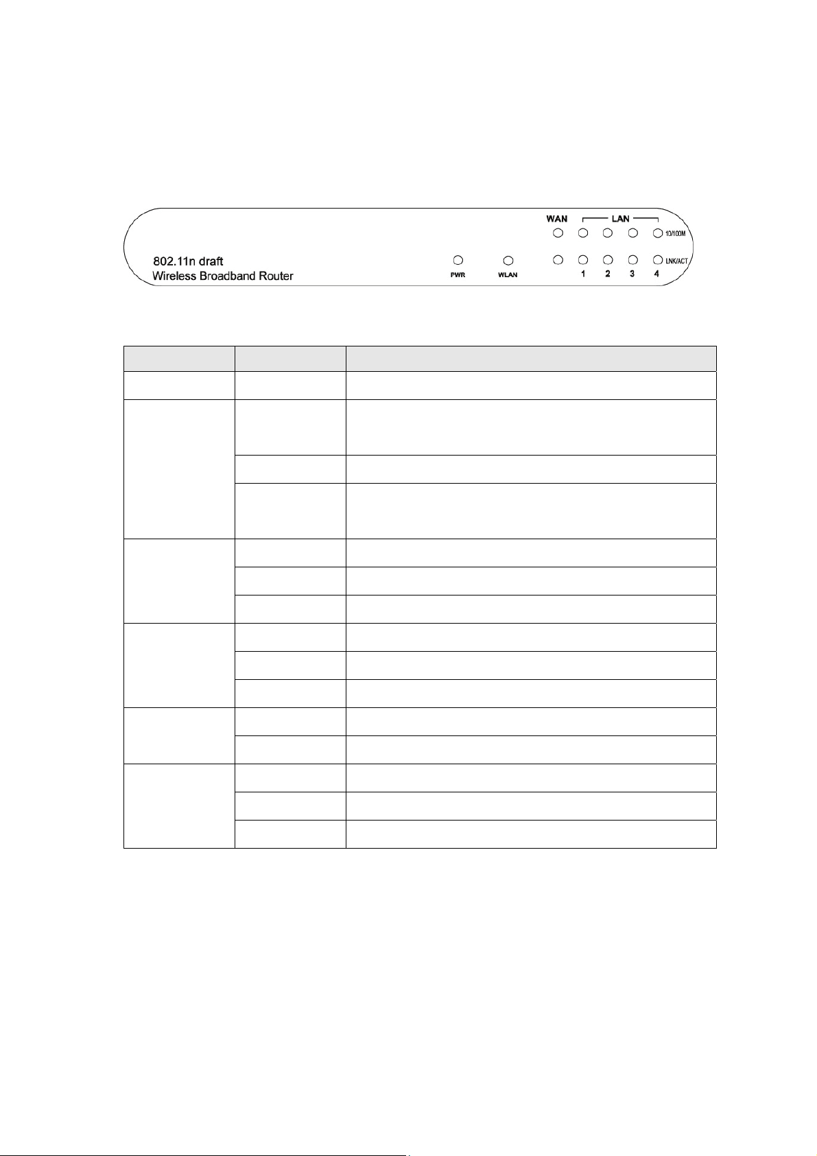
Front Panel
LED Name Light Status Description
PWR ON Router is switched on and correctly powered
On Wireless network is switched on or WPS
mode is on.
WLAN
WAN
10/100M
WAN
LNK/ACT
10/100M
LAN
LNK/ACT
Off Wireless network is switched off
Flashing Wireless LAN activity (transferring or
receiving data).
On WAN port (Internet) is running at 100Mbps
Off WAN port (Internet) is running at 10Mbps
Flashing WAN activity (transferring or receiving data)
On WAN port is connected
Off WAN port is not connected
Flashing WAN activity (transferring or receiving data)
On LAN port is running at 100Mbps LAN
Off LAN port is running at 10Mbps
On LAN port is connected
Off LAN port is not connected
Flashing LAN activity (transferring or receiving data)
Page 14
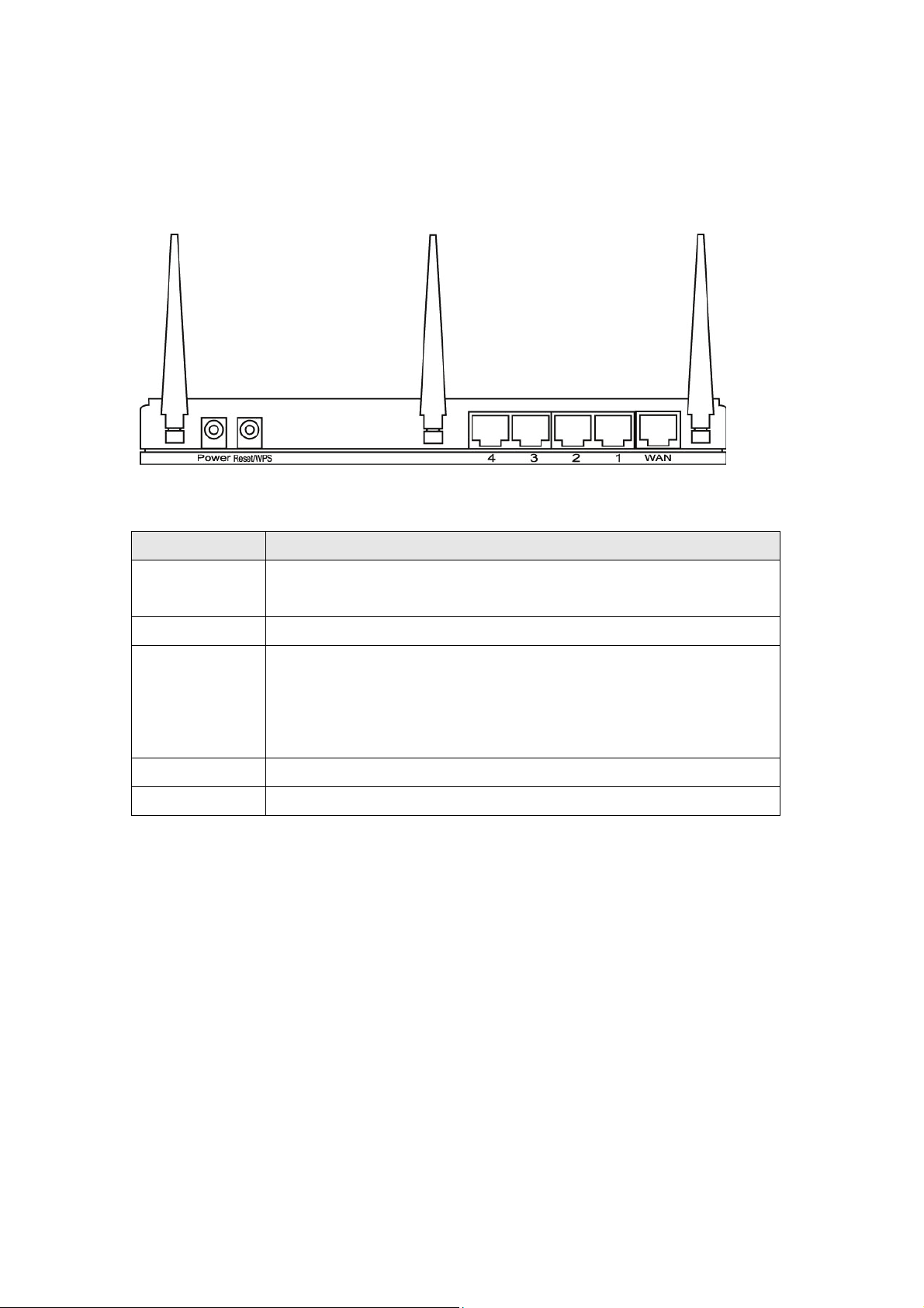
Back Panel
Antenna A Antenna B Antenna C
Item Name Description
Antennas A to C 3dBi dipole antennas.
Power Power connector, connects to A/C power adapter.
Reset / WPS Reset the router to factory default settings (clear all settings) or
start WPS function. Press this button and hold for 10 seconds to
restore all settings to factory defaults, and press this button for less
than 5 seconds to start WPS function.
1 - 4 Local Area Network (LAN) ports 1 to 4.
WAN Wide Area Network (WAN / Internet) port.
Page 15
Chapter II: System and Network Setup
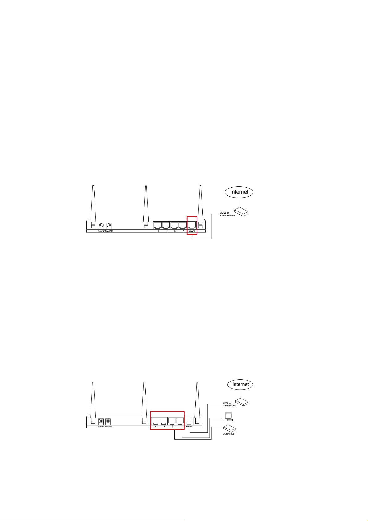
2-1 Connecting the Wireless Broadband Router
This chapter explains how to connect the router to your computers and
how to access the Internet.
1. Connect your DSL or cable modem to the WAN port of router using
the provided RJ45 Ethernet cable.
Standard modems provided by Internet Service Providers (also referred to
as ISPs) come with at least one LAN or Ethernet port. This is the port
which you need to connect to the WAN port of the INTELLINET
NETWORK SOLUTIONS Wireless N Broadband Router.
2. Connect all your computers, network devices (network-enabled
consumer devices other than computers, like game consoles, network
media players, network storage units or LAN switches) to the LAN
ports of the router.
Page 16
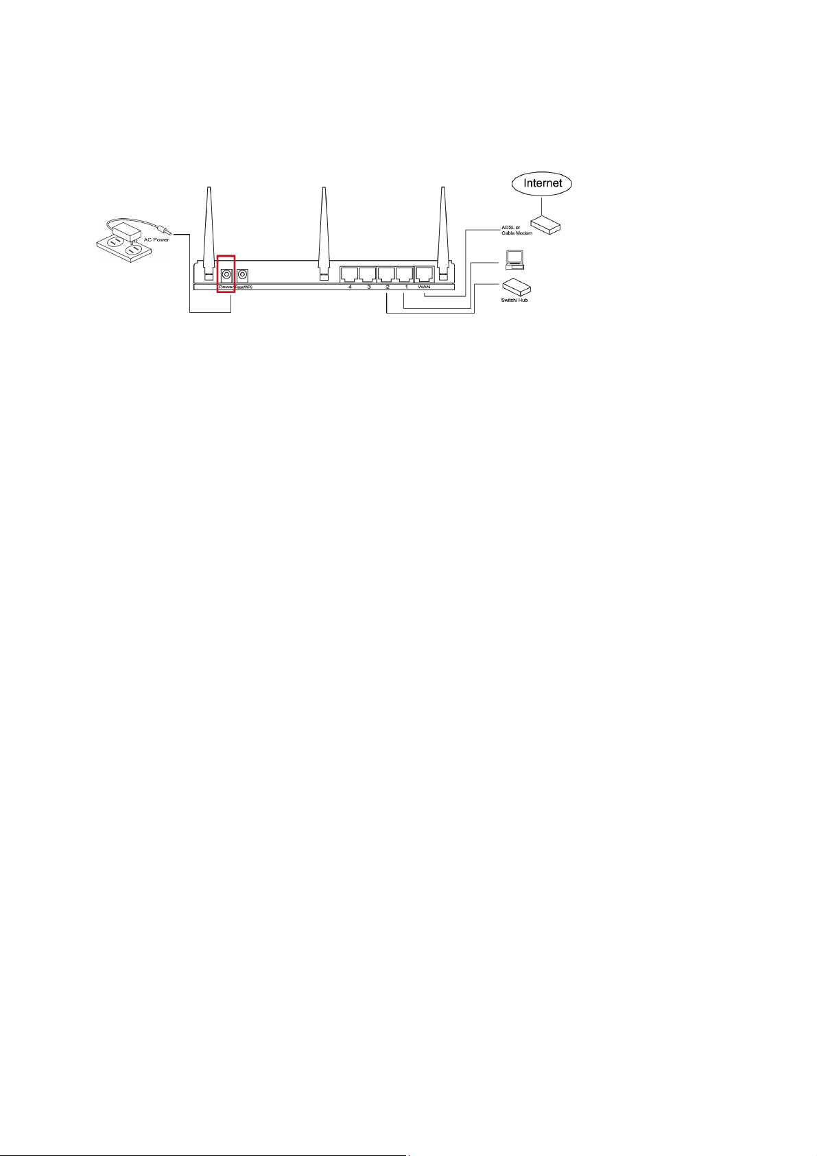
3. Connect the A/C power adapter to the wall socket, and then connect it
to the 'Power' socket of the router.
4. Check all LEDs on the front panel.
The 'PWR' LED should be steadily on, WAN and LAN LEDs should
be on if the computer or network device connected to the respective
port of the router is powered on and correctly connected.
If the PWD LED is not on, or any LED you expected to be on is not
on, please recheck the cabling, or go to chapter '4-2 Troubleshooting'
for possible reasons and solutions.
Page 17
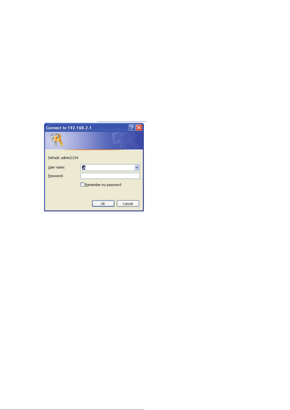
2-2 Connecting to the Wireless Broadband Router
Before you can connect to the router and start configuration procedures,
your computer must be able to get an IP address automatically (use
dynamic IP address). This is the default setup for any standard Windows
computer, and it normally is not required to make any changes.
Connect your computer to one of the LAN ports of the router, then
activate the network connection. Start the Web browser; e.g., MS Internet
Explorer, and open http://192.168.2.1
Only if the steps above are not successful, or if you know that your
computer has a static IP address setup, do you need to follow the
instructions below:
.
A login window opens up:
Enter 'admin' as the username and
'1234' as the password.
If this works, you can skip the next
pages and go directly to chapter
"2-3 Using 'Quick Setup'".
If the operating system of your computer is….
Windows 95/98/Me - go to section 2-2-1
Windows 2000 - go to section 2-2-2
Windows XP - go to section 2-2-3
Windows Vista - go to section 2-2-4
Page 18
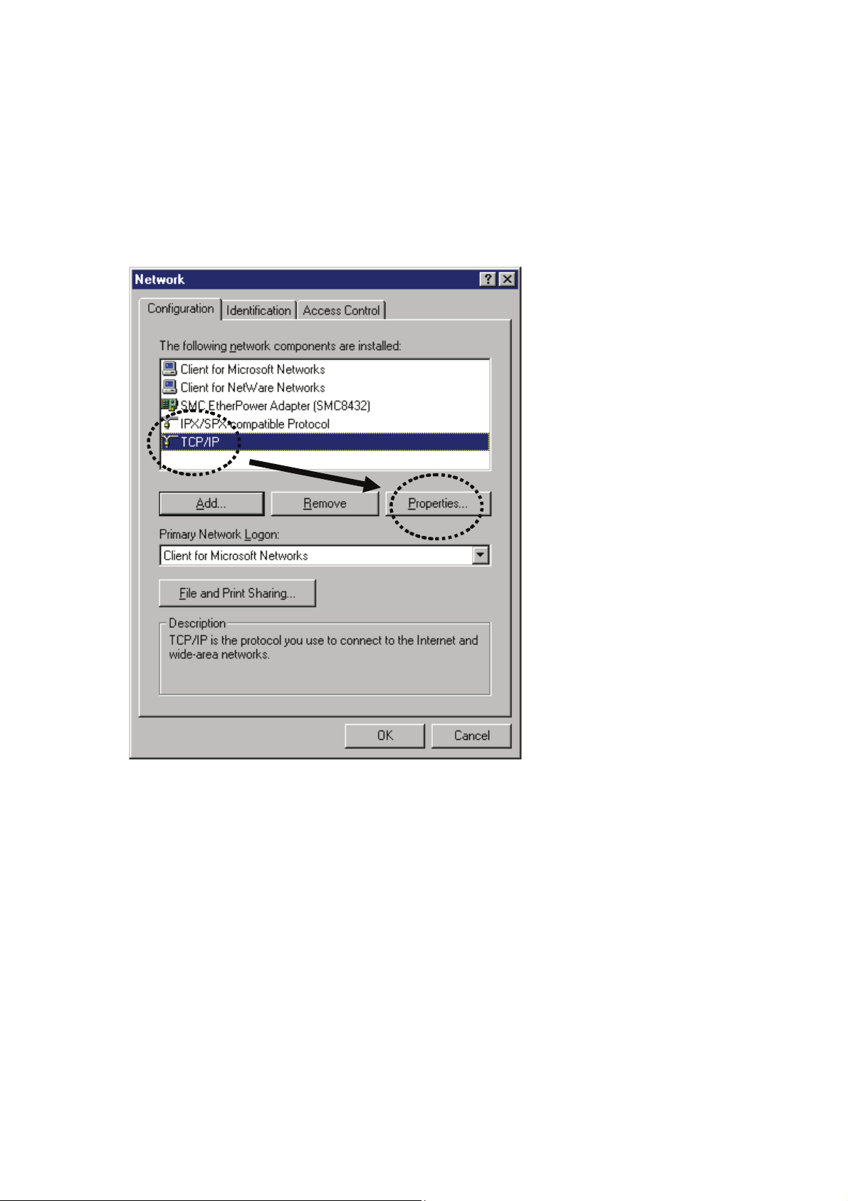
2-2-1 Windows 95/98/Me IP address setup:
1. Click 'Start' button, then click control panel. Double-click the Network
icon, and the Network window will appear. Select 'TCP/IP', then click
'Properties'.
Page 19
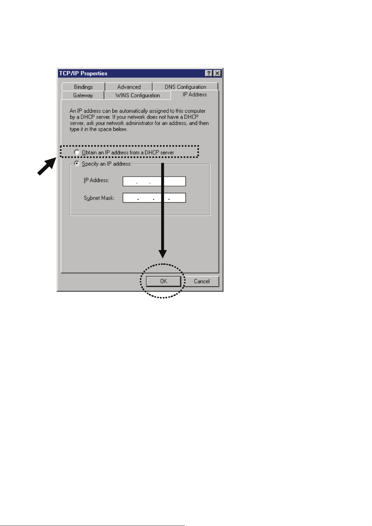
2. Select 'Obtain an IP address from a DHCP server' and then click 'OK'.
Page 20
2-2-2Windows 2000 IP address setup:
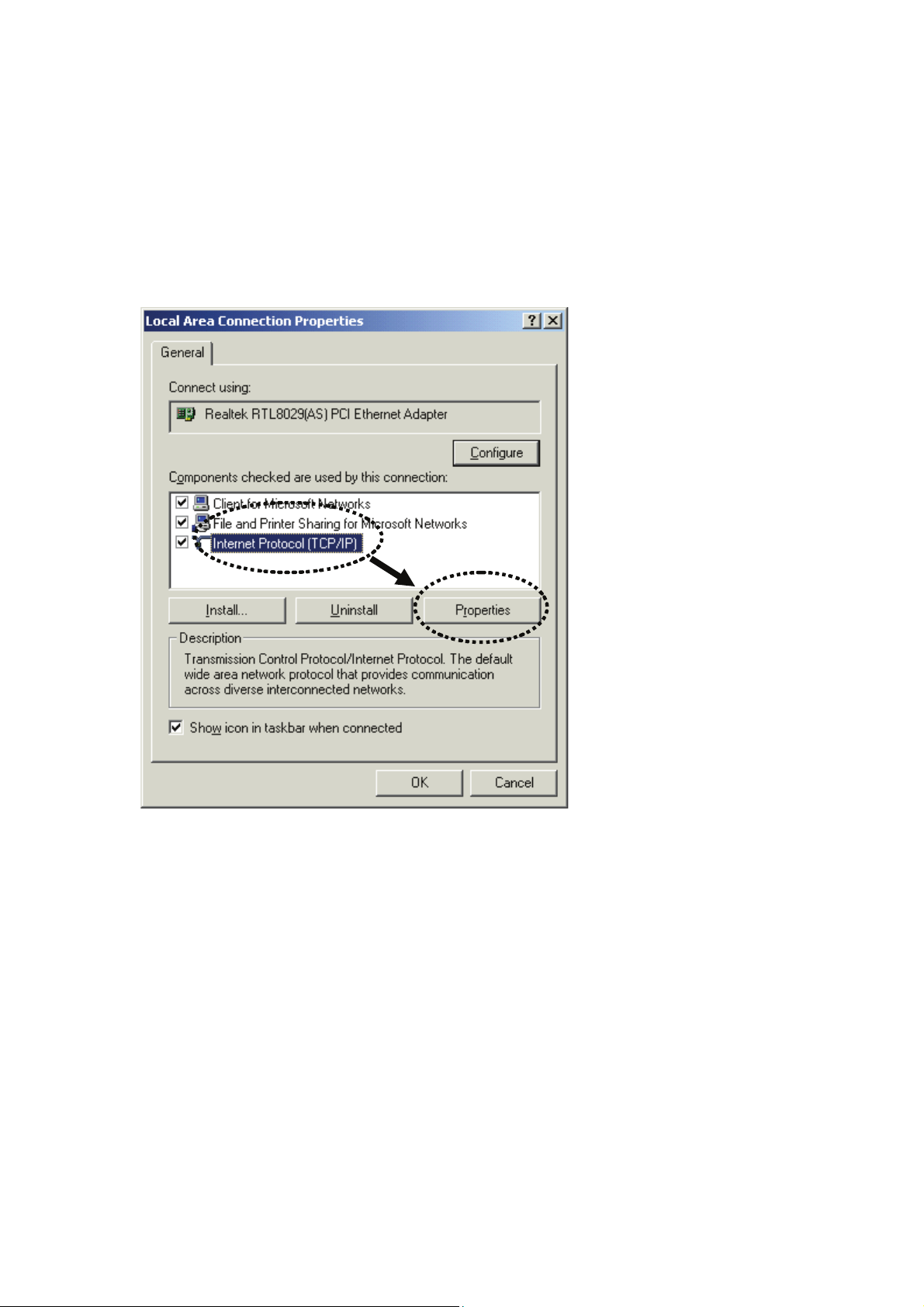
1. Click 'Start' button, then click control panel. Double-click the Network
and Dial-up Connections icon; click Local Area Connection, and the
Local Area Connection Properties window will appear. Select 'Internet
Protocol (TCP/IP)' and then click 'Properties'.
Page 21
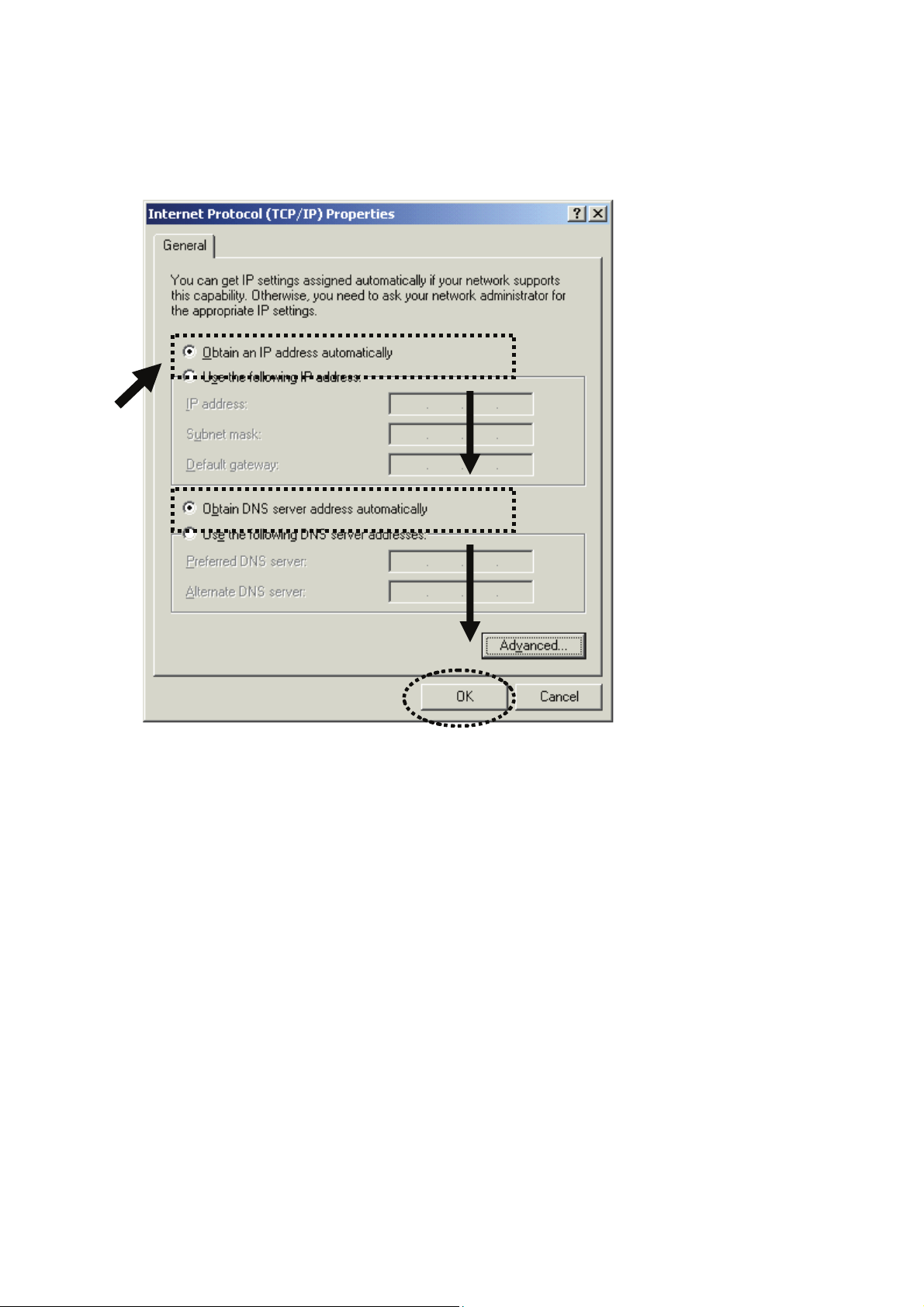
2. Select 'Obtain an IP address automatically' and 'Obtain DNS server
address automatically', then click 'OK'.
Page 22
2-2-3Windows XP IP address setup:
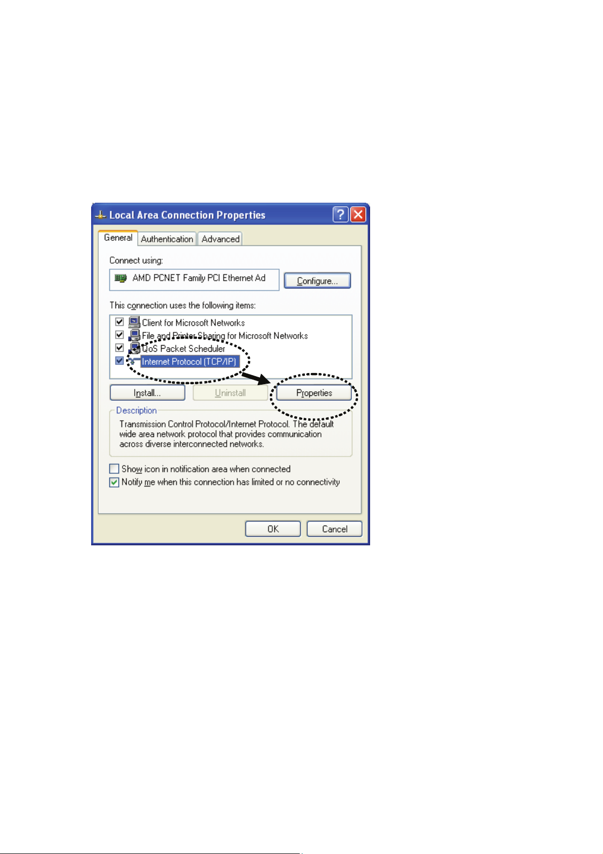
1. Click the 'Start' button, then click 'control panel'. Double-click the
Network and Internet Connections icon, click Network Connections,
then double-click Local Area Connection. The Local Area Connection
Status window will appear, and then click 'Properties'.
Page 23
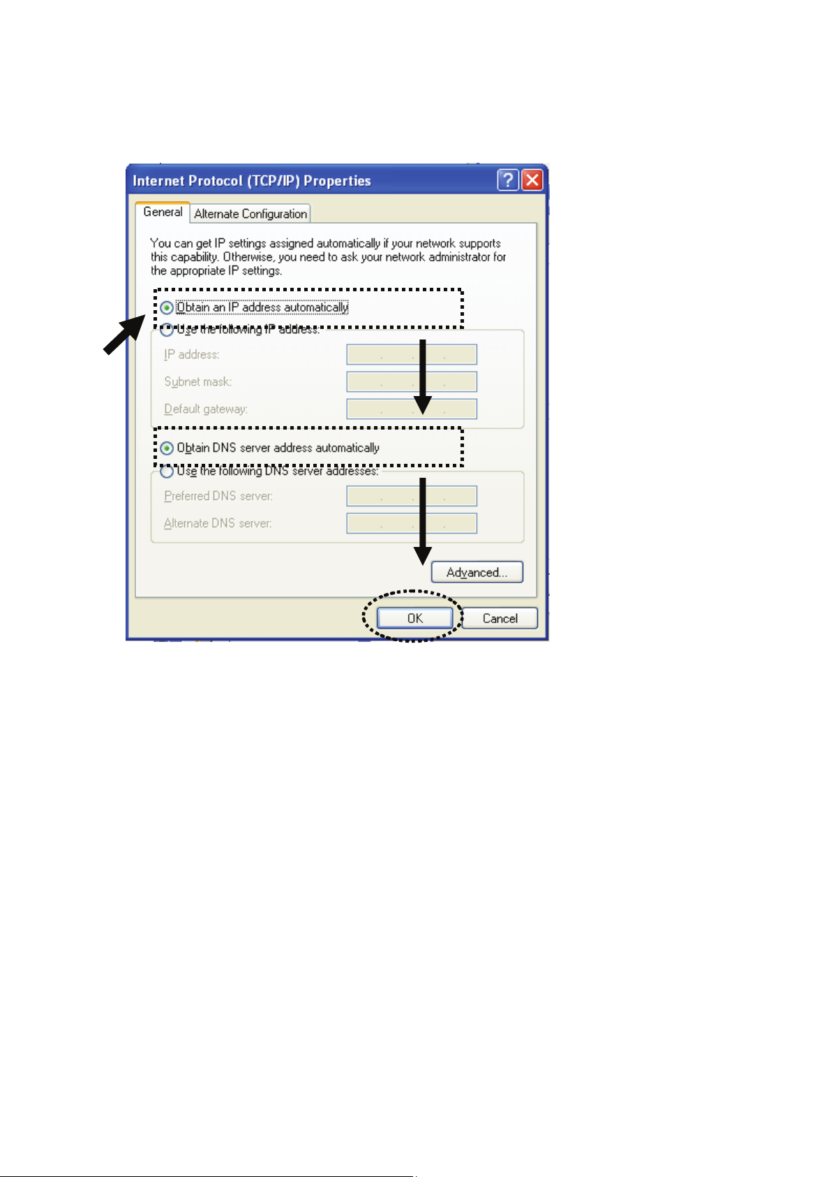
2. Select 'Obtain an IP address automatically' and 'Obtain DNS server
address automatically', then click 'OK'.
Page 24
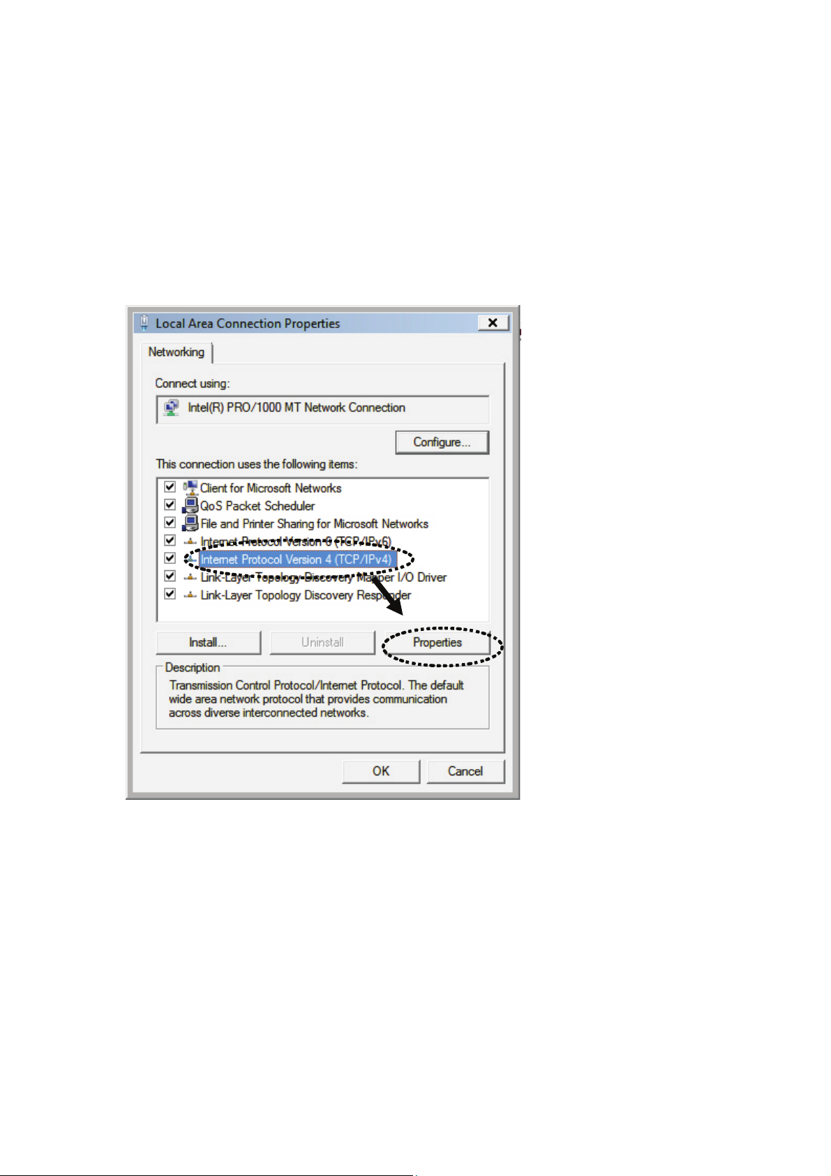
2-2-4Windows Vista IP address setup:
1. Click the 'Start' button, then click 'control panel'. Click View Network
Status and Tasks, and then click Manage Network Connections.
Right-click Local Area Network, then select 'Properties'. The Local
Area Connection Properties window will appear, select 'Internet Protocol
Version 4 (TCP / IPv4), and then click 'Properties'.
Page 25
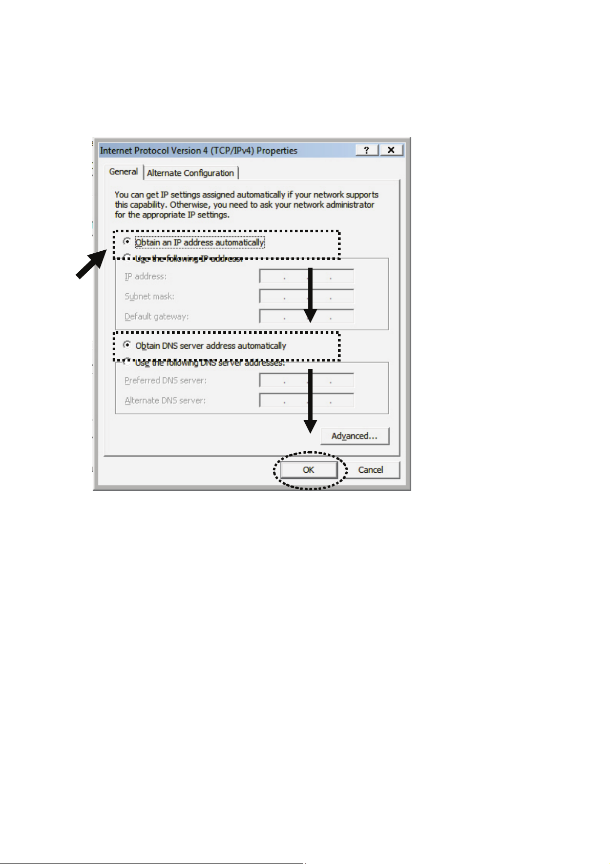
2. Select 'Obtain an IP address automatically' and 'Obtain DNS server
address automatically', then click 'OK'.
Page 26
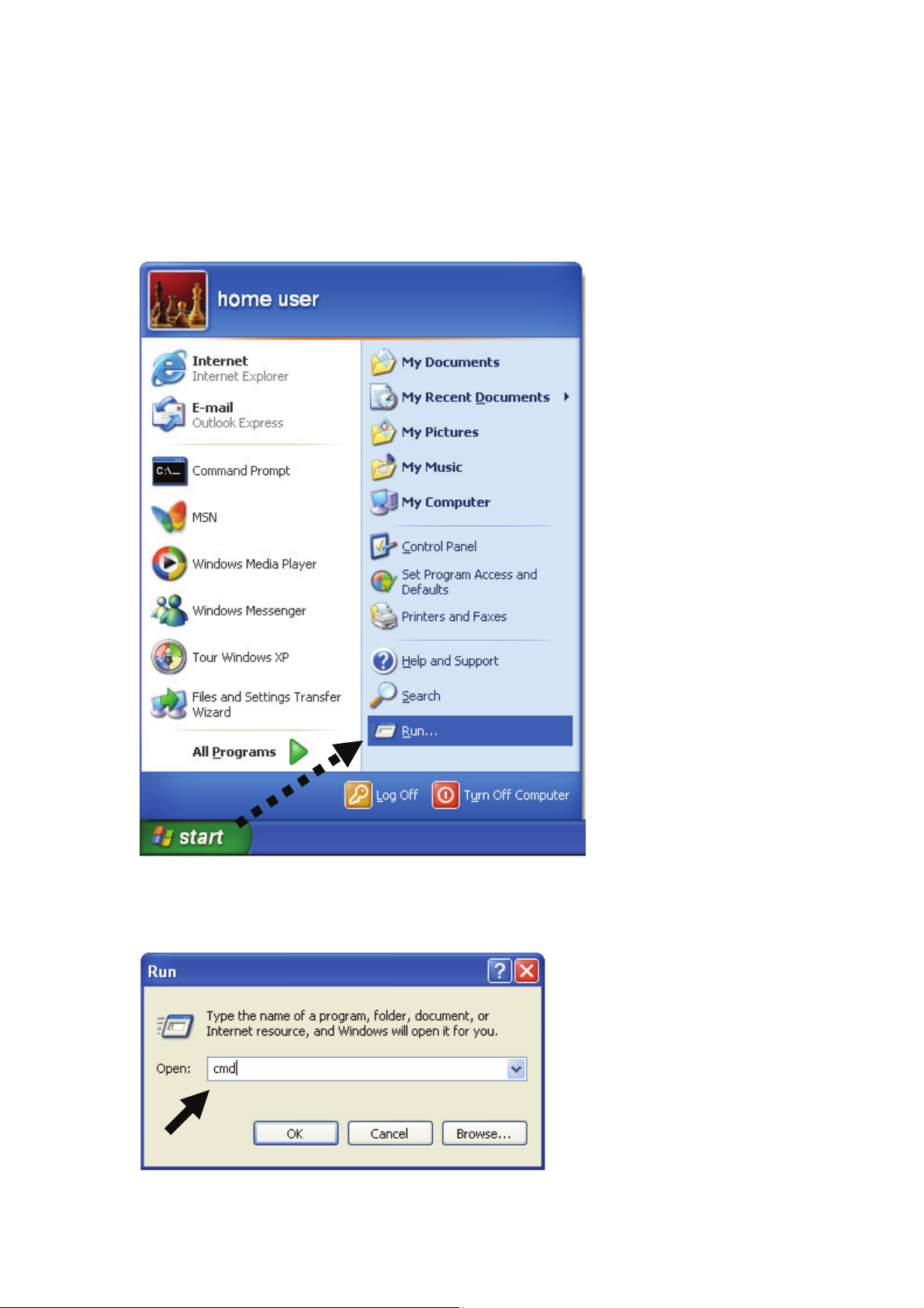
2-2-5 Router IP address lookup
After the IP address setup is complete, Click 'start' -> 'run' at the
bottom-left corner of your desktop:
Input 'cmd', then click 'OK'.
Page 27
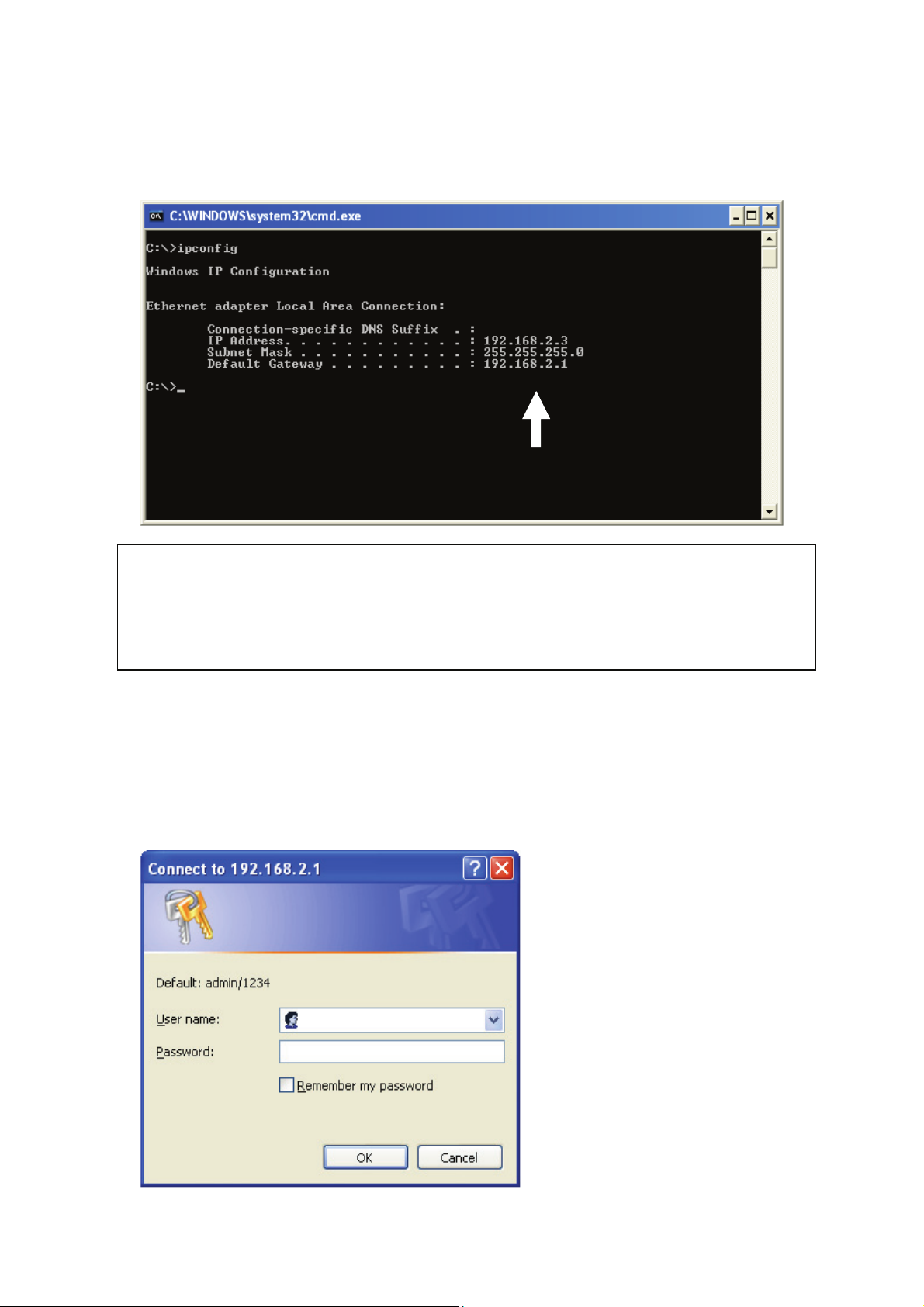
Input 'ipconfig', then press the 'Enter' key. Check the IP address followed
by 'Default Gateway', in this example, the IP address of the router is
192.168.2.1, please note that this value may be different.
NOTE: If the IP address of the Gateway is not displayed, or the address
followed by ‘IP Address’ begins with ‘169’, recheck the network connection
between your computer and the router, and go to the beginning of this
chapter to recheck every step of the network setup procedure.
3. Connect the router's management interface by the Web browser
After your computer has obtained an IP address from the router, start your
Web browser, and input the IP address of the router into the address bar.
The following message should be shown:
Page 28
Enter user name and password. The default user name is 'admin', and
default password is '1234'. Press 'OK', and you can see the Web
management interface of this router:
NOTE: If you can’t see the Web management interface, and you’re
being prompted to input the user name and password again, it means
you didn’t input the correct username and password. Retype user
name and password. If you’re certain that the user name and
password you typed are correct, please go to ‘4-2 Troubleshooting’ to
perform a factory reset to set the password back to default value.
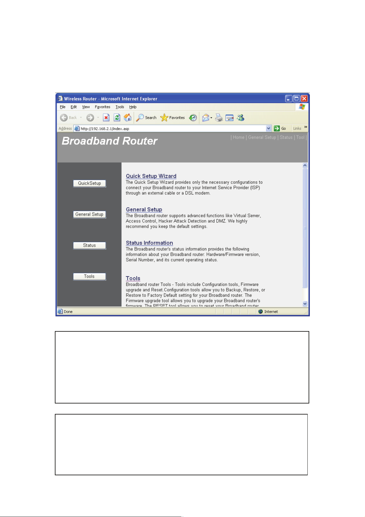
TIP: This page shows the four major setting categories: QuickSetup,
General Setup, Status, and Tools. You can find the shortcut which
leads to these setting categories at the upper-right corner of every
page, and you can jump to another category directly by clicking the
link.
Page 29
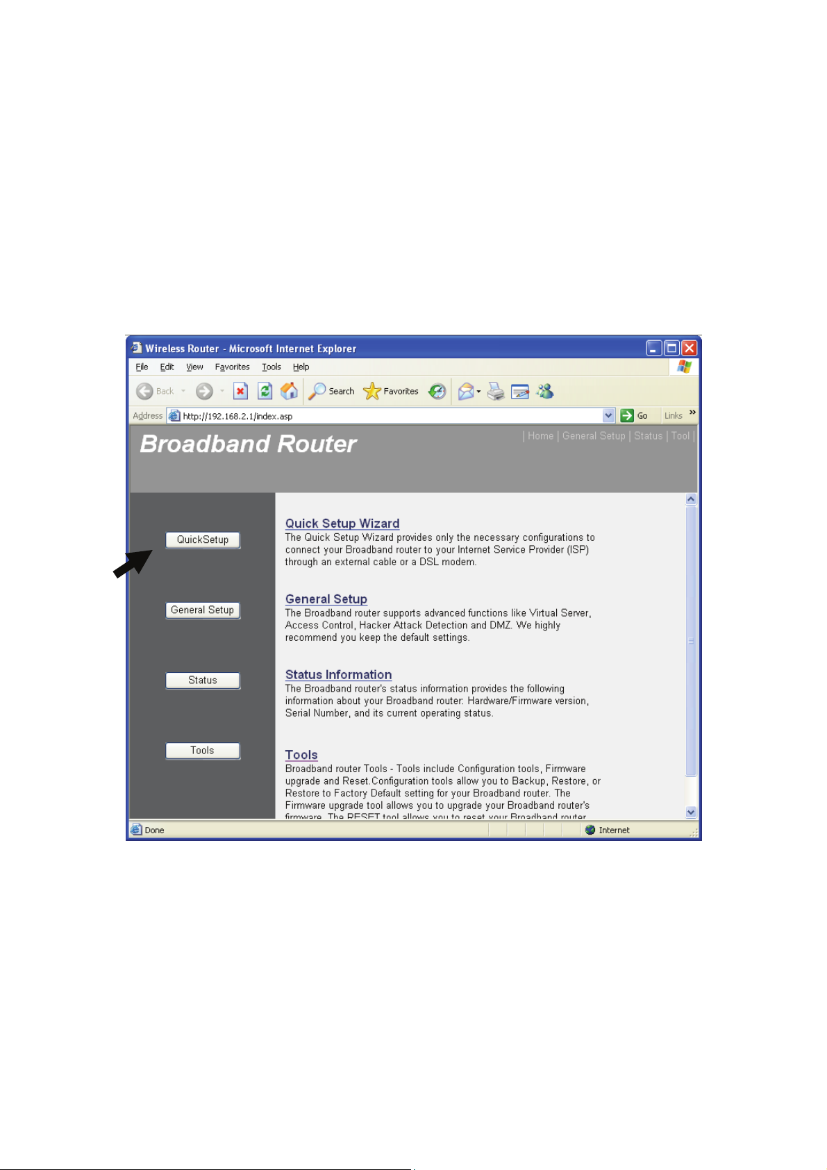
2-3 Using Quick Setup
This router provides a Quick Setup procedure, which will help you to
complete all required settings you need to access the Internet quickly.
Follow the instructions below to complete the 'Quick Setup':
Please go to the QuickSetup menu by clicking 'QuickSetup' button.
HERE!
Page 30
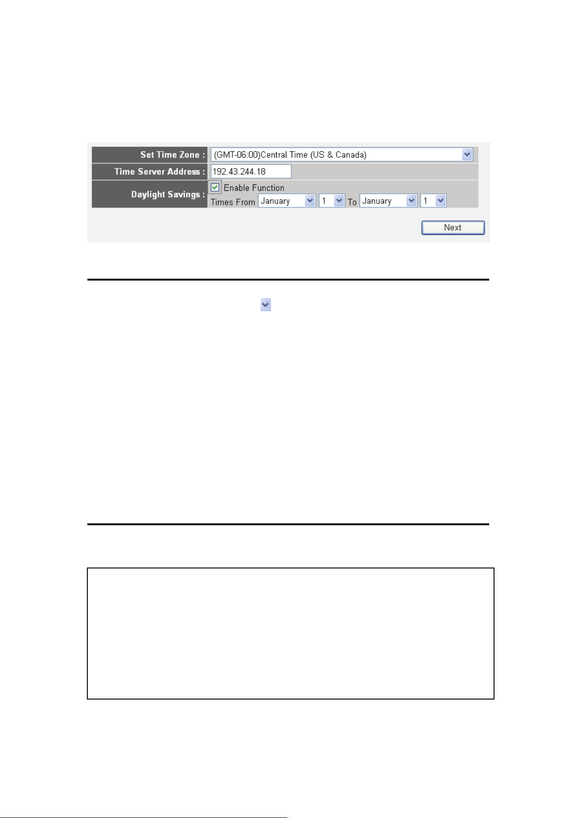
The following message will be displayed:
3
1. Set Time Zone
Items and meanings:
1
2
4
Set Time (1): Press the
button to open a drop-down list and
Select the time zone of the location you live in.
Time Server Input the IP address / host name of time server
Address (2): here. It is normally not required to make a change.
However, should the default Time Server
(NTP Server) go offline, you can obtain a new NTP
Server at http:/www.ntp.org.
Daylight If the country you live in uses daylight saving,
Savings (3): activate the 'Enable Function' and choose the
duration of daylight saving.
Click 'Apply'.
NOTE: There are several time (NTP) servers available on the Internet:
132.163.4.101 (time-a.timefreq.bldrdoc.gov)
A list of free NTP Servers is available at http://www.ntp.org.
129.6.15.28 (time-a.nist.gov)
131.107.1.10 (time-nw.nist.gov)
Page 31

2. Broadband Type
Choose the broadband (Internet connection) type you use; there are six
types of Internet connections:
Cable Modem - Please go to section 2-3-1
Fixed-IP xDSL - Please go to section 2-3-2
PPPoE xDSL - Please go to section 2-3-3
PPTP xDSL - Please go to section 2-3-4
L2TP xDSL - Please go to section 2-3-5
Telstra Big Pond - Please go to section 2-3-6
Cable Modem and PPPoE xDSL are the most common connection types.
If you're not sure which service you have, contact your Internet service
provider (ISP). You will not be able to connect to the internet if the wrong
connection type is chosen.
NOTE: DSL Internet Service Providers normally operate using the
PPPoE protocol, thus, "PPPoE xDSL" should be the Broadband Type.
However, in recent years more DSL ISPs provide customers with DSL
Modems which handle the PPPoE portion of the Internet Access
automatically. In those cases you must select "Cable Modem" as your
Broadband type, even if you have a DSL service.
Page 32

2-3-1 Setup procedure for Cable Mode':
1
2
Items and meanings:
Host Name (1): Input the host name of your computer. This is
optional, and only required if your service provider
asks you to do so.
MAC address (2): Enter the MAC address of your computer here, if
your service provider only permits a computer with
3
a certain MAC address to access the Internet. If
you're using a computer used to connect to the
Internet via cable modem, you can simply press the
'Clone Mac address' button to fill the MAC address
field with the MAC address of your computer.
To save the settings click the 'OK' button; if you want to go back to the
previous menu, click 'Back'.
Page 33

2-3-2 Setup procedure for 'Fixed-IP xDSL':
1
2
3
4
Items and meanings:
IP address Enter the IP address assigned by your
Service Internet Service Provider (ISP).
Provider (1):
5
Subnet Mask (2): Input the subnet mask assigned by your service
provider
DNS address (3): Enter the IP address of the DNS server provided by
your ISP.
Service Provider Enter the Gateway IP address provided by your
Gateway ISP.
Address (4):
To save the settings, click the 'OK' button; if you want to go back to
previous menu, click 'Back'.
NOTE: You can choose this Internet connection method if your
service provider assigns a fixed IP address (also know as static
address) to you, and doesn't use DHCP or PPPoE protocol. Contact
your service provider for further information.
Page 34

2-3-3 Setup procedure for 'PPPoE xDSL':
1
2
3
4
5
6
Items and meanings:
User Name (1): Enter the user name assigned by your Internet
service provider here.
7
Password (2): Input the password assigned by your Internet
service provider here.
Service Name (3): Provide a name for this Internet service. This is
optiona.l
MTU (4): Enter the MTU value of your network connection
here. Use default value unless your
ISP specifies otherwise.
Connection (5): Select the connection type(detailed explanation
listed below).
Idle Time Out (6): Specify the idle time out, (detailed explanation listed
below).
To save the settings click the 'OK' button; if you want to go back to the
previous menu, click 'Back'.
Page 35

Connection Type - There are 3 options:
"Continuous’"- keep the Internet connection alive, do not disconnect.
This is the preferred choice for "always on" / "Flat rate" Internet
services.
"Connect on Demand" - only connects to the Internet when there’s a
connect attempt. This is the preferred choice for all users who have
paid per minute Internet Service or per transferred data.
"Manual" - only connects to the Internet when the ‘Connect’ button on
this page is pressed, and disconnects when the ‘Disconnect button is
pressed.
2-3-4 Setup procedure for 'PPTP xDSL':
PPTP xDSL requires two kinds of settings: WAN interface setting (setup
IP address) and PPTP setting (PPTP user name and password).
We start with the WAN interface settings:
Select how you obtain IP address from your service provider here. You
can choose 'Obtain an IP address automatically' (equal to DHCP, refer to
'Cable Modem' section above), or 'Use the following IP address' (i.e.,
static IP address).
The WAN interface settings must be correctly entered, or the Internet
connection will fail even if the PPTP settings are correct. Contact your
ISP if you don't know how you should fill in these fields.
Page 36

PPTP settings section:
1
3
4
5
6
7
Items and meanings:
User ID (1): Enter the user ID (user name) assigned by your ISP.
Password (2): Input the password provided by your ISP.
8
PPTP Input the IP address of PPTP gateway
Gateway (3): assigned by your Internet service provider here.
Connection Enter the connection ID here. This is
ID (4): optional and you can leave it blank.
MTU (5): Specify the MTU value of your network connection
here. Use the default value unless your ISP specifies
otherwise.
Connection Select the connection type - see xDSL PPPoE.
type (6):
Idle Time Specify the idle time out - see xDSL PPPoE.
Out (7):
Enabling 'BEZEQ-ISRAEL' is only required if you're using the BEZEQ
network provider in Israel.
To save the settings click the 'OK' button; if you want to go back to the
previous menu, click 'Back'.
Page 37

2-3-5 Setup procedure for 'L2TP xDSL':
L2TP is another popular connection method for xDSL and other Internet
connection types, and all required setting items are the same as the PPTP
connection.
As with PPTP there are two kinds of settings. Fist come the 'WAN
Interface Settings':
Select how you obtain an IP address from your service provider here. You
can choose 'Obtain an IP address automatically' (equal to DHCP, refer to
'Cable Modem' section above) or 'Use the following IP address' (i.e. static
IP address).
The WAN interface settings must be correctly entered or the Internet
connection will fail even if the L2TP settings are correct. Contact your
ISP if you don't know how you should fill in these fields.
Page 38

2-3-4 Setup procedure for 'L2TP':
1
2
3
4
5
6
7
Items and meanings:
User ID (1): Enter the user ID assigned by your ISP.
Password (2): Type in the password assigned by your ISP.
L2TP Gateway (3): Input the IP address of the L2TP gateway assigned
by your ISP here.
MTU (4): Specify the MTU value of your network connection
here. Use the default value unless your ISP specifies
otherwise.
Connection Select the connection type- see xDSL PPPoE.
type (5):
Idle Time Specify the idle time out - see xDSL PPPoE.
Out (6):
To save the settings, click the 'OK' button; if you want to go back to the
previous menu, click 'Back'.
Page 39

2-3-6 Setup procedure for 'Telstra Big Pond':
1
3
This setting only works when you're using Telstra Big Pond's network
service in Australia. You need to input:
User Name (1): Input the user name assigned by Telstra.
Password (2): Input the password assigned by Telstra.
User device login Check this box to choose the login server
server manually (3): by yourself.
Login Server (4): Enter the IP address of the login server here.
2
4
5
To save the settings click the 'OK' button; if you want to go back to the
previous menu, click 'Back'.
When all settings are finished, you'll see the following message displayed
on your Web browser:
Page 40

Click the 'Apply' button to prepare to restart the router, and you'll see this
message:
Wait for about 30 seconds, then click 'OK!'.
You'll be forwarded to the router management Web interface. The router
is now running with the new settings.
If all information entered is correct, you can access the Internet now.
Attention DSL Users:
While PPPoE is the most common way to connect to DSL Internet Service,
it still may be necessary to enable "Cable Modem" in the Broadband
settings.
Below are a few examples for using "Cable Modem" instead of "xDSL
PPPoE", even if your Internet Service is a DSL service.
• Your ISP has provided you with a so-called 'Modem-Router' instead
of a simple "Modem"
• You ISP has not given you a username and password for PPPoE
login (implying that it is not required)
• When your computer is connected directly to the modem, the
Computer obtains an IP address which is in the private IP network
range (192.168.xxx.yyy, 10.xxx.yyy, 172.16.xxx.yyy)
• You can connect to the Internet with your computer connected
directly to the modem without using a dialer program asking for a
username and password
• If your attempts to utilize xDSL/PPPoE fail repeatedly you should
activate "Cable Modem" as a troubleshooting step.
Page 41

2-4 Basic Setup
In this chapter, you'll learn how to change the time zone, password, and
remote management settings. Start your Web browser and logon to the
router's Web management interface by opening http://192.168.2.1, then
click the 'General Setup' button on the left.
HERE!
2-4-1 Time zone and time auto-synchronization
Follow the following instructions to set time zone and time
auto-synchronization parameters:
Click the 'System' menu on the left of the Web management interface,
then click 'Time Zone', and the following message will be displayed on
your Web browser: Please select time zone at 'Set time zone' drop-down
list, and input the IP address or host name of the time server. If you want
to enable daylight saving setting, check the 'Enable Function' box, and set
the duration of daylight saving.
Page 42

Click 'Apply'. You'll see the following message displayed on Web
browser:
Press 'Continue' to save the settings and make additional changes; press
'Apply' to save the settings and restart the router so the settings will take
effect after it reboots.
NOTE: You can refer to the instructions given in the last chapter
‘Using Quick Setup’ for detailed descriptions on the time zone
settings.
2-4-2 Change management password
The default password of this router is 1234, and it's displayed on the login
prompt when accessed from the Web browser. There's a security risk if
you don't change the default password, since everyone can see it. This is
very important when you have the wireless function enabled.
To change the password, do as follows:
Click the 'System' menu on the left of the Web management interface,
then click 'Password Settings', and the following message will be
displayed on your Web browser:
2
3
Page 43

Items and meanings:
Current Enter the current password here (e.g., 1234)
Password (1):
New Password (2): Enter the new password here.
Confirmed Enter the new password here again.
Password (3):
Click 'Apply' to save the changes. If you want to keep the original
password unchanged, click 'Cancel'.
If the passwords you typed in 'New Password' (2) and 'Confirmed
Password' (3) field are not the same, you'll see the following message:
Please retype the new password when you see above message.
If you see the following message …
… it means that the content in the 'Current Password' field is wrong,
Click 'OK' to go back to the previous menu, and try to input the current
password again.
If the current and new passwords are correctly entered, after you click
'Apply', you'll be prompted to re-login.
Page 44

Use the username "admin" and the new password to re-login.
2-4-3 Remote Management
This router by default does not allow management access from the
Internet to prevent possible security risks (especially when you have
defined a weak password, or didn't change the default password).
However, you can still manage this router from a specific IP address by
enabling the 'Remote Management' function.
Click the 'System' menu on the left of Web management interface, then
click 'Remote Management', and the following screen will be displayed
on your Web browser:
Page 45

Items and meanings:
Host Address (1): Input the IP address of the remote host you wish to
initiate a management access.
Port (2): You can define the port number through which this
router should expect an incoming request. If you're
providing a Web service (default port number is 80),
you should try to use another port number. You can
use the default port setting '8080', or something like
'32245' or '1429' (any integer between 1 and
65534).
Enabled (3): Select the field to start the configuration.
When you finish with all settings, click 'Apply', and you'll see the
following message displayed on Web browser:
Press 'Continue' to save the settings and continue with more configuration
options; press 'Apply' to save the settings and restart the router so the
settings will take effect after it reboots.
Page 46

NOTE: When you want to manage this router from another computer
on the Internet, you have to input the IP address and port number of
this router. If your Internet service provider assigns you with a static
IP address, it will not be a problem; but if the IP address your service
provider assigns to you will vary every time you establish an Internet
connection, this will be a problem.
Either ask your service provider to give you a static IP address, or use
a dynamic DNS services like DDNS.
Refer to chapter 2-5-8 ‘DDNS client’ for details.
NOTE: The default port number the Web browser will use is ‘80’. If the
‘Port’ setting in this page is not ‘80’, you have to assign the port
number in the address bar of the Web browser manually. For
example, if the IP address of this router is 1.2.3.4, and the port
number you set is 8888, you have to input the following address in the
address bar of the Web browser:
http://1.2.3.4:8888
Page 47

2-5 Setup Internet Connection (WAN Setup)
Internet connection setup can be done by using the 'Quick Setup' menu
described in chapter 2-3. However, you can set the WAN connections up
by using the WAN configuration menu. You can also program advanced
functions like DDNS (Dynamic DNS) here.
Click the 'WAN' menu on the left of the Web management interface, and
the following screen will be displayed:
Select an Internet connection method based on the type of connection
you're using. You can either click the connection method on the left (1) or
right (2). If you select the connection method on the right, Click the
'More Configuration' button after a method is selected.
Dynamic IP - Refer to section 2-5-1
Static IP - Refer to section 2-5-2
PPPoE - Refer to section 2-5-3
PPTP - Refer to section 2-5-4
L2TP - Refer to section 2-5-5
Telstra Big Pond - Refer to section 2-5-6
DNS - Refer to section 2-5-7
DDNS - Refer to section 2-5-8
Page 48

2-5-1 Setup procedure for 'Dynamic IP':
1
2
3
Items and meanings:
Host Name (1): Enter the host name of your computer; this is
optional and is only required if your service
provider asks you to do so.
MAC Address (2): Enter the MAC address of your computer if your
service provider only permits a computer with a
certain MAC address to access the Internet. If
you're using the computer used to connect to the
Internet via cable modem, you can simply press the
'Clone Mac address' button to fill the MAC address
field with the MAC address of your computer.
Click 'Apply' (3) to save the settings, and 'Cancel' to remove the
information entered.
After you click 'Apply', the following message will be displayed on your
Web browser:
Page 49

Click 'Continue' (1) to go back to the previous setup menu and to
continue with the router setup. Click 'Apply' to reboot the router so the
settings will take effect. Please wait for about 30 seconds while the router
is rebooting.
2-5-2 Setup procedure for 'Static IP':
1
2
3
4
Items and meanings:
IP address assigned Enter the IP address assigned
by your Service by your service provider.
Provider (1):
Subnet Mask (2): Enter the subnet mask assigned by your service
provider.
Service Provider Enter the IP address of the Gateway
Gateway Address (3): server provided by your service provider.
Click 'Apply' (3) to save the settings and 'Cancel' to remove the
information entered.
Page 50

5 6
Click 'Continue' to go back to the previous setup menu and to continue
with the router setup. Click 'Apply' to reboot the router so the settings
will take effect. Please wait for about 30 seconds while the router is
rebooting.
2-5-3 Setup procedure for 'PPPoE':
1
2
3
4
7
Items and meanings:
User Name (1): Enter the user name assigned by your Internet
service provider here.
Password (2): Enter the password assigned by your Internet
service provider here.
Service Name (3): Enter a name for this Internet service; this is
optional.
MTU (4): Specify the MTU value of your network connection
here. Use the default value unless your ISP specifies
otherwise.
Connection Please select the Internet connection type you
Type (5): wish to use.
Page 51

Continuous – The connection will always be kept on. If
the connection is interrupted, the router will re-connect
automatically.
Connect On-Demand – Only connect when you want to
surf the Internet. “Idle Time Out” is set to stop the
connection when the network traffic is not sending or
receiving after an idle time.
Manual – After you have selected this option, you will
see the “Connect” button and “Disconnect” button.
Click “'Connect” and the router will connect to the
ISP. If you want to stop the connection, click the
“Disconnect” button.
Idle Time Out (6): If you have selected “Connect-On-Demand”, enter
the idle time out.
Click 'Apply' (3) to save the settings and 'Cancel' to remove the
information entered.
Click 'Continue' to go back to the previous setup menu and to continue
with the router setup. Click 'Apply' to reboot the router so the settings
will take effect. Please wait for about 30 seconds while the router is
rebooting.
Page 52

2-5-4 Setup procedure for 'PPTP':
PPTP requires two kinds of settings: WAN interface setting (setup IP
address) and PPTP setting (PPTP user name and password). Here we start
with the WAN interface setting:
Select how you obtain an IP address from your service provider here. You
can choose 'Obtain an IP address automatically' (equal to DHCP, refer to
the 'Cable Modem' section above), or 'Use the following IP address' (i.e.,
static IP address).
WAN interface settings must be correctly set or the Internet connection
will fail even if the PPTP settings are correct. Contact your Internet
service provider if you don't know how you should fill in these fields.
Go to PPTP settings section next.
Page 53

1
3
4
5
6
7
8
Items and meanings:
User ID (1): Enter the user ID (user name) assigned by your
Internet service provider here.
9
Password (2): Enter the password assigned by your Internet
service provider here.
PPTP Gateway (3): Enter the IP address of the PPTP gateway assigned
by your Internet service provider here.
Connection ID (4): Enter the connection ID here. This is optional and
you can leave it blank.
MTU (5): Specify the MTU value of your network connection
here. Use the default value unless your ISP specifies
otherwise.
BEZEQ-ISRAEL (6): If you are connecting to the BEZEQ network in
Israel, you need to enable this function.
Connection Select the Internet connection type you
type (7): wish to use. Refer to section 2-5-3 for detailed
descriptions.
Page 54

Idle Time Out (8): Enter the idle time out of the Internet connection
you wish to use, and refer to section 2-5-3 for
detailed descriptions.
Click 'OK' (9) to save the settings and 'Back' if you want to go back to the
previous menu.
2-5-5 Setup procedure for 'L2TP':
1
2
3
4
5
6
7
Items and meanings:
User ID (1): Enter the user ID (user name) assigned by your Internet
service provider here.
Password (2): Enter the password assigned by your Internet service
provider here.
L2TP Enter the IP address of the L2TP gateway
Gateway (3): assigned by your Internet service provider here.
MTU (4): Specify the MTU value of your network connection here.
Use default value unless your ISP specifies otherwise.
Connection Select the Internet connection type you wish
type (5): to use; refer to section 2-5-3 for detailed descriptions.
Idle Time Enter the idle time out of the Internet connection
Out (6): you wish to use, and refer to section 2-5-3 for detailed
descriptions.
Page 55

Click 'OK' (7) to save the settings and 'Back' if you want to go back to the
previous menu.
2-5-6 Setup procedure for 'Telstra Big Pond':
1
3
This setting only works when you're using Telstra Big Pond's network
service in Australia. You need to input:
Items and meanings:
User Name (1): Enter the user name assigned by Telstra.
Password (2): Enter the password assigned by Telstra.
User device login Check this box to choose the login server by
server manually (3): yourself.
2
4
5
Login Server (4): Enter the IP address of login server here.
When you finish with all settings, click 'OK' (5); if you want to go back
to previous menu, click 'Back'.
Page 56

2-5-7 Setup procedure for 'DNS':
If you select 'Dynamic IP' or 'PPPoE' as the Internet connection method,
the ISP typically assigns the DNS Server information to the router.
However, if you have a preferred DNS server, use a static IP address or
your service provider didn't assign the IP address of the DNS server for
any reason, you can input the IP address of the DNS server here.
1
2
3
Items and meanings:
DNS Address (1): Enter the IP address of the DNS server provided by
your service provider.
Secondary Enter the IP address of the secondary DNS
DNS Address (2): server provided by your service provider. This is
optional.
NOTE: Only IP address can be entered here; DO NOT use the hostname
of the DNS server! (i.e., only numeric characters and dots are
accepted)
10.20.30.40……………………………………………………………… Correct
dns.serviceprovider.com…………………………………………... Incorrect
Click 'Apply' (3) to save the settings and 'Cancel' to remove the
information entered.
Page 57

Click 'Continue' to go back to the previous setup menu and to continue
with the router setup. Click 'Apply' to reboot the router so the settings
will take effect. Please wait for about 30 seconds while the router is
rebooting.
2-5-8 Setup procedure for 'DDNS':
DDNS (Dynamic DNS) is an IP-to-Hostname mapping service for those
Internet users who don't have a static (fixed) IP address. It will be a
problem when a user wants to provide services to other users on the
Internet, because their IP addresses will vary every time they connect, and
they will not be able to know the IP address they're using at a certain
time.
This router supports the DDNS service of several service providers, for
example:
DynDNS (http://www.dyndns.org
TZO (http://www.tzo.com
Go to one of the DDNS service provider's Webpages listed above, and get
a free DDNS account using the instructions on their Web page.
)
)
Page 58

1
3
4
5
Items and meanings:
Dynamic DNS (1): If you want to enable the DDNS function, select
'Enabled'; otherwise select 'Disabled'.
Provider (2): Select your DDNS service provider here.
Domain Name (3): Input the domain name you've obtained from DDNS
service provider.
Account / Input the user account of your DDNS registration.
6
E-Mail (4):
Password / Key (5): Input the DDNS service password or key.
Click 'Apply' (6) to save the settings and 'Cancel' to remove the
information entered.
Click 'Continue' to go back to the previous setup menu and to continue
with the router setup. Click 'Apply' to reboot the router so the settings
will take effect. Please wait for about 30 seconds while the router is
rebooting.
Page 59

2-6 LAN Configuration
This section deals with the IP Address settings of the local network.
Normally there is no need
to make any changes here. The default
values work fine for most applications; you can skip this chapter and
go directly to 2-7 WLAN configuration.
There are two ways to assign IP addresses to computers: static IP address
(set the IP address for every computer manually), and dynamic IP address
(IP address of computers will be assigned by the router automatically).
It's recommended for most of the computers to use a dynamic IP address,
as it will save a lot of time when setting IP addresses for every computer,
especially when there are a lot of computers in your network. For servers
and network devices which will provide services to other computer and
users that come from the Internet, a static IP address should be used, so
other computers can locate the server.
Suggestions on IP address numbering plan:
If you have no idea how to define an IP address plan for your
network, here are some suggestions.
1. A valid IP address has 4 fields: a.b.c.d for most home and
company users, it’s suggested to use 192.168.c.d, where c is
an integer between 0 and 254, and d is an integer between 1
and 254. This router is able to work with up to 253 clients, so
you can set the ‘d’ field of the IP address of the router as 1 or
254 (or any number between 1 and 254), and pick a number
between 0 and 254 for field ‘c’.
2. In most cases, you should use ‘255.255.255.0’ as the subnet
mask, which allows up to 253 clients (this also meets the
router’s capability of working with up to 253 clients).
3. For all servers and network devices which will provide
services to other people (like Internet service, print service,
and file service), they should use a static IP address. Give
each of them a unique number between 1 and 253, and
maintain a list, so everyone can locate those servers easily.
4. For computers which are not dedicated to providing specific
service to others, they should use a dynamic IP address.
If you don’t really understand the descriptions listed above, don’t
worry! We will provide recommended setup values below.
Page 60

Follow the following instructions to set wired LAN parameters:
Click the 'LAN' menu on the left of the Web management interface. There
are three setup groups here: 'LAN IP', 'DHCP Server', and 'Static DHCP
Leases Table'. Here are setup instructions for each of them:
2-6-1 LAN IP section:
1
2
3
4
Items and meanings:
IP address (1): Enter the IP address of this router.
Subnet Mask (2): Enter the subnet mask for this network.
802.1d If you wish to activate the 802.1d spanning tree
Spanning Tree (3): function, select 'Enabled' for setup item '802.1d
Spanning Tree', or set it to 'Disabled'.
DHCP Server (4): If you want to activate the DHCP server function of
this router, select 'Enabled', or set it to 'Disabled'.
Recommended values if you don’t know what to enter:
IP Address: 192.168.2.1
Subnet Mask: 255.255.255.0
802.1d Spanning Tree: Disabled
DHCP Server: Enabled
Page 61

2-6-2 DHCP Server:
These settings are only available when 'DHCP Server' in the 'LAN IP'
section is 'Enabled', and here are descriptions for the setup items:
Lease Time (1): Choose a lease time (the duration that every
computer can keep a specific IP address) from
dropdown menu of every IP address assigned by this
router.
1
2
3
4
Start IP (2): Enter the start IP address of the IP range.
End IP (3): Enter the end IP address of the IP range.
Domain Name (4): If you wish, you can also input the domain name for
your network. This is optional.
Recommended values if you don’t know what to enter:
Lease Time: Two Weeks (or ‘Forever’, if you have fewer than 20 computers)
Start IP: 192.168.2.100
End IP: 192.168.2.200
Domain Name: (leave it blank)
NOTE:
1. The number of the last field ( ‘d’ field) of ‘End IP’ must be greater
than ‘Start IP’, and can not be the same as the router’s IP address.
2. The former three fields of the IP address of ‘Start IP’, ‘End IP’, and ‘IP
Address of ‘LAN IP’ section ( ‘a’, ‘b’, and ‘c’ fields) should be the same.
3. These settings will affect wireless clients, too.
Page 62

2-6-3 Static DHCP Leases Table:
This function allows you to assign a static IP address to a specific
computer forever, so you don't have to set the IP address for a
computer, but you can still enjoy the benefit of using a DHCP server. A
maximum of 16 static IP addresses can be assigned here.
(If you set 'Lease Time' to 'forever' in the 'DHCP Server' section, you
can also assign an IP address to a specific computer permanently;
however, you will not be able to assign a certain IP address to a
specific computer, since IP addresses will be assigned in random order
this way).
1
2 3 4
Items and meanings:
Enable Static Check this box to enable this function,
DHCP Leases (1): or uncheck it to disable this function.
MAC Address (2): Input the MAC address of the computer or
network device (a total of 12 characters, with
numerals from 0 to 9, and characters from a to f,
like '001122aabbcc').
IP address (3): Input the IP address you want to assign to this
computer or network device.
'Add' (4): After you input the MAC address and IP address
pair, click this button to add the pair to the static
DHCP leases table.
If you want to remove all the characters you just entered, click 'Clear'.
After you click 'Add', the MAC address and IP address mapping will
be added to the 'Static DHCP Leases Table' section.
Page 63

1
2 3 4
If you want to delete a specific item, check the 'Select' box of a MAC
address and IP address mapping (1), then click the 'Delete Selected'
button (2); if you want to delete all mappings, click 'Delete All' (3). If
you want to deselect all mappings, click 'Reset' (4).
Click 'Apply' to save the settings.
Click 'Continue' to go back to the previous setup menu and to continue
with the router setup. Click 'Apply' to reboot the router so the settings
will take effect. Please wait for about 30 seconds while the router is
rebooting.
Page 64

2-7 Wireless LAN Configuration
If your computer, PDA, game console, or other network devices
equipped with a wireless network interface, you can use the wireless
function of this router to connect to the Internet and share resources
with other computers on your network. We strongly recommend you
use the built-in security functions to protect your network from
intruders.
The following pages describe the wireless configuration.
Click the 'Wireless' menu on the left of the Web management interface to
open the wireless settings page. Here you can enable or disable the
wireless radio of the router. By default, the wireless functionality is
enabled. Click the 'Apply' button to save your settings.
Click 'Apply' to save the settings.
Click 'Continue' to go back to the previous setup menu and to continue
with the router setup. Click 'Apply' to reboot the router so the settings
will take effect. Please wait for about 30 seconds while the router is
rebooting.
Page 65

2-7-1 Basic Wireless Settings
Click the 'Wireless' menu on the left of the Web management interface,
then click 'Basic Settings' and the following screen appears:
Band:
2.4 GHz (B) 2.4 GHz band, only allows an 802.11b wireless network
client to connect to this router (maximum transfer rate of
11Mbps).
2.4 GHz (N) 2.4 GHz band, only allows an 802.11n wireless network
client to connect to this router (maximum transfer rate of
300Mbps).
2.4 GHz (B+G) 2.4 GHz band, only allows a802.11b and 802.11g
wireless network clients to connect to this router
(maximum transfer rate 11Mbps for 802.11b clients, and
maximum 54Mbps for 802.11g clients).
2.4 GHz (G) 2.4 GHz band, only allows an 802.11g wireless network
client to connect to this router (maximum transfer rate of
54Mbps).
2.4 GHz (B+G+N) 2.4 GHz band, allows 802.11b, 802.11g, and 802.11n
wireless network clients to connect to this router
(maximum transfer rate of 11 Mbps for 802.11b clients,
maximum of 54 Mbps for 802.11g clients, and a
maximum of 300 Mbps for 802.11n clients).
NOTE:
Choose ‘2.4 GHz (B+G+N) for maximum wireless client compatibility.
Page 66

ESSID: Enter the name for your wireless network. You may
choose to leave the default value, but you can adjust
the value to make identification in areas with
different Wireless networks easier; e.g., to
differentiate your wireless network from that of your
neighbors.
Channel Number (4): Select a channel from the dropdown list of 'Channel
Number'. Available channel numbers are 1 to 13 for
European countries, 1 to 11 for USA. You can
choose any of these channels.
Associated Clients (5): Click the 'Show Active Clients' button to see the
status of all active wireless stations that are
connected to the access point.
You can try to change the channel number if you think the data
transfer rate is too slow. There could be interference from other
wireless networks in the area using the same channel, and the
cross-talk between the two networks reduces the wireless data
transfer rate. Ideally, you want
to set your channel to a value which leaves at least two channels
spaced between the two networks, three is even better.
Example:
The wireless network of the neighbor runs on Channel 3.
You should set your channel to at least Channel 6.
It is also possible for a handheld phone in your household to cause
interference with the wireless signal. In such a case, changing the
channel by two or three numbers often resolves the problem.
Page 67

2-7-2 Advanced Wireless Settings
This chapter describes advanced wireless settings. Normally there is no
need to make any changes here. Unless you know that your network
requires special settings, you can skip this chapter and go straight to
'2-7-3 Wireless Security'.
1
2
3
4
5
6
7
8
9
10
11
12
Items and meanings:
Fragment Set the Fragment threshold of wireless radio.
Threshold (1): Do not modify the default value if you don't know
what it should be, default value is 2346.
RTS Threshold (2): Set the RTS threshold of wireless radio. Do not
modify the default value if you don't know what it
should be, default value is 2347.
Beacon Interval (3) Set the beacon interval of wireless radio. Do not
modify the default value if you don't know what it
should be, default value is 100.
Page 68

DTIM Period(4): Set the DTIM period of the wireless radio. Do not
modify the default value if you don't know what it
should be, default value is 3.
Data Rate(5): Set the wireless data transfer rate to a specific value.
Since most of wireless devices will negotiate with
each other and pick a proper data transfer rate
automatically, it's not necessary to change this
value unless you know what will happen after
modification.
N Data Rate(6): Same as above, but only for 802.11n clients.
Channel Width (7): Set the channel width of wireless radio. Do not
modify default the value if you don't know what it
should be, default setting is 'Auto 20/40 MHz'.
Preamble Type (8): Set the type of preamble, do not modify default
value if you don't know what it is, default setting is
'Short Preamble'.
Broadcast ESSID (9): Decide if the wireless router will broadcast its
own ESSID or not. You can hide the ESSID of your
wireless router (set the option to 'Disable'), so only
people who know the ESSID of your wireless router
can connect to it.
CTS Protect (10): Enabling this setting will reduce the chance of radio
signal collisions between 802.11b and 802.11g/n
wireless access points. It's recommended to set this
option to 'Auto' or 'Always'. However, if you set to
'None', your wireless router should be able to work
fine, too.
Tx Power (11): You can set the output power of the wireless radio.
Unless you're using this wireless router in a really
big space, you may not have to set output power to
100%.
Page 69

WMM (12): Short for Wi-Fi MultiMedia, it will enhance the data
transfer performance of multimedia contents when
it's being transferred over wireless network. If you
don't know what it is or not sure if you need it, it's
safe to set this option to 'Enable'. The default
setting is 'Disable'.
Click 'Apply' to save the changes.
Click 'Continue' to go back to the previous setup menu and to continue
with the router setup. Click 'Apply' to reboot the router so the settings
will take effect. Please wait for about 30 seconds while the router is
rebooting.
Page 70

2-7-3 Wireless Security
Unlike the previous chapter, which dealt with advanced settings you
normally don't need to change, this chapter is of great importance. It
explains how you can protect your wireless network from
unauthorized access.
It's very important to program the wireless security settings properly! If
you don't, freeloaders may use your Internet connection without your
knowledge or, worst case, hackers may gain access to your network to
steal data; e.g., bank details, credit card information, etc.
Click 'Security Settings' in the 'Wireless' menu on the left, then follow the
instructions below to set the wireless security settings:
Please select an encryption method from 'Encryption' dropdown menu.
There are four options:
2-7-3-1 Disable wireless security
When you select this mode, data encryption is disabled, and every
wireless device in proximity will be able to connect your wireless router
if no other security measure is enabled (like MAC address access control
- see section 2-7-4, or disable ESSID broadcast).
Only use this option when you really want to allow everyone to use your
wireless router, and you don't care if someone reads the data you
transfer over the network without your consent.
Page 71

2-7-3-2 WEP - Wired Equivalent Privacy
WEP encryption is an outdated method to secure your network. It
does not meet the security standards of modern data encryption.
It is not recommended to use WEP, unless you use WLAN adapters
or WLAN networking devices which do not support WPA/WPA2
encryption.
If your WLAN card supports WPA/WPA2, you can skip this chapter
and go straight to chapter 2-7-3-3 Wi-Fi Protected Access (WPA).
When you select this mode, the wireless router will use WEP encryption,
and the following setup menu will be shown on your Web browser:
1
2
3
4
5
6
7
8
9
Items and meanings:
Key Length (2): There are two types of WEP key length: 64-bit and
128-bit. Using '128-bit' is safer than '64-bit', but
will reduce some data transfer performance.
Key Format (3): There are two types of key format: ASCII and Hex.
When you select a key format, the number of
characters of the key will be displayed. For example,
if you select '64-bit' as the key length, and 'Hex' as
the key format, you'll see the message at the right of
10
'Key Format' is 'Hex (10 characters), which means
the length of WEP key is 10 characters.
Page 72

Default Tx Key (4): You can set up to four sets of WEP keys, and you
can decide which key is being used by default here.
If you don't know which one you should use, select
'Key 1'.
Encryption Key Input WEP key characters here. The number of
1 to 4 (5-8): characters must be the same as the number
displayed n the 'Key Format' field. You can use any
alphanumerical characters (0-9, a-z, and A-Z) if
you select 'ASCII' key format. If you select 'Hex' as
key the format, you can use characters 0-9, a-f, and
A-F. You must enter at least one encryption key here,
and if you entered multiple WEP keys, they should
not be same.
Enable 802.1x IEEE 802.1x is an authentication protocol. Every
Authentication (9): user must use a valid account to login to this
wireless router before accessing the wireless LAN.
The authentication is processed by a RADIUS server.
This mode authenticates the user by IEEE 802.1x,
but it does not encrypt the data during
communication. If there is a RADIUS server in your
environment, enable this function. Check this box
and another sub-menu will appear:
RADIUS Server Enter the IP address of the radius
IP address (11): server here.
RADIUS Server Enter the port number of the radius
11
12
13
Port (12): server here.
RADIUS Server Enter the port number of the radius
Password (13): password here.
Page 73

Some examples of WEP key
(Don’t use these examples; use your own!):
ASCII (5 characters): pilot
ASCII (13 characters): digitalFAMILY
Hex (10 characters): 287d2aa732
Hex (26 characters): 9284bcda8427c9e036f7abcd84
To improve the security level, do not use words which can be found in
a dictionary or are too easy to remember! (‘pilot’ above is a bad
example and is just intended to show you how a WEP key looks).
Wireless clients will remember the WEP key, so you only have to input
the WEP key for a wireless client once. It’s worth using a complicated
WEP key to improve security level.
Note: We recommend using 128-bit encryption and ASCII as the key
format.
Then you enter your WEP key consisting of 13 characters into the
configuration and save the settings. Now all Wireless clients will have
to enter those 13 characters to gain access to your wireless network.
Click 'Apply' to save the settings.
Click 'Continue' to go back to the previous setup menu and to continue
with the router setup. Click 'Apply' to reboot the router so the settings
will take effect. Please wait for about 30 seconds while the router is
rebooting.
Page 74

2-7-3-3 Wi-Fi Protected Access (WPA):
When you select this mode, the wireless router will use WPA encryption,
and the following setup menu will be displayed.
1
2
3
4
Items and meanings:
WPA Unicast Select a type of WPA cipher suite.
Cipher Suite (2): Available options are: WPA (TKIP), WPA2 (AES),
and WPA2 Mixed. You can select one of them, but
you have to make sure your wireless clients support
the cipher you selected.
Pre-shared Select the type of pre-shared key. You can select
Key Format (3): Passphrase (8 or more alphanumerical characters,
up to 63), or Hex (64 characters of 0-9, and a-f).
Pre-shared Enter the WPA passphrase here.
Key (4): It's not recommended to use a word that can be
found in a dictionary for security reasons.
5
Click 'Apply' button (5) to save the settings and the following message
will be displayed:
Page 75

Click 'Continue' to go back to the previous setup menu and to continue
with the router setup. Click 'Apply' to reboot the router so the settings
will take effect. Please wait for about 30 seconds while the router is
rebooting.
NOTE: Some wireless clients (especially those manufactured before
2003) only support WEP or WPA (TKIP) cipher. A driver upgrade would
be needed for those clients to be able to use WPA and WPA2
encryption.
2-7-3-4 WPA RADIUS:
If you have a RADIUS server, this router can work with it and provide
safer wireless authentication.
1
2
3
4
5
6
Items and meanings:
WPA Unicast Select a type of WPA cipher suite.
Cipher Suite: Available options are: WPA (TKIP), WPA2 (AES),
and WPA2 Mixed. You can select one of them, but
you have to make sure that your wireless client or
network card supports the cipher you selected.
RADIUS Server Enter the IP address of your Radius
IP address (3): authentication server here.
RADIUS Server Enter the port number of your Radius
Port (4): authentication server here. The Default setting is
1812.
RADIUS Server Enter the password of your Radius
Password (5): authentication server here.
Page 76

Click 'Apply' (6) to save the settings.
Click 'Continue' to go back to the previous setup menu and to continue
with the router setup. Click 'Apply' to reboot the router so the settings
will take effect. Please wait for about 30 seconds while the router is
rebooting.
2-7-4 Wireless Access Control
This function helps to prevent unauthorized users from connecting to
your wireless router; only those wireless devices who have the MAC
address you assigned here can gain access to your wireless router. The
MAC address is a unique hardware identification number which every
network adapter carries. You can use this function in combination with
data encryption (WPA, WPA2 or WEP) to create an additional layer of
security for your wireless network.
Up to 20 MAC addresses can be assigned using this function. Click
'Wireless' menu on the left of the Web management interface, then click
'Access Control', and the following message will be displayed on your
Web browser:
Page 77

1
2 3 4
5
All allowed MAC addresses will be displayed in 'MAC Address Filtering
Table' (1). Here are the items and descriptions:
Delete Selected (2): If you want to delete a specific MAC address entry,
check the Select' box of the MAC address you want
to delete, then click the 'Delete Selected' button.
(You can select more than one MAC address at a
time).
Delete All (3): If you want to delete all MAC addresses listed here,
click 'Delete All'.
Reset (4): You can also click 'Reset' to de-select all MAC
addresses.
Enable Wireless To enforce MAC address filtering, you have
Access Control (5): to check 'Enable Wireless Access Control'. When
this item is unchecked, the wireless router will not
filter the MAC addresses of wireless clients.
MAC Address (6): Input the MAC address of your wireless devices here
without special characters. If the MAC address label
of your wireless device indicates 'aa-bb-cc-dd-ee-ff'
or 'aa:bb:cc:dd:ee:ff', just input 'aabbccddeeff'.
Comment (7): You can input any text here as the comment of this
MAC address, like 'Company Notebook'. You can
Page 78

input up to 16 alphanumerical characters here.
This is optional and you can leave it blank;
however, it's recommended to use this field
so you can identify the MAC addresses later.
Add (8): Click the 'Add' button to add the MAC address and
associated comment to the MAC address filtering
table.
Clear (9): Click 'Clear' to remove the value you input in MAC
address and comment field.
Click 'Apply' (10) to save the settings.
Click 'Continue' to go back to the previous setup menu and to continue
with the router setup. Click 'Apply' to reboot the router so the settings
will take effect. Please wait for about 30 seconds while the router is
rebooting.
Page 79

2-7-5 Wi-Fi Protected Setup (WPS)
Wi-Fi Protected Setup (WPS) is the simplest way to build a connection
between wireless network clients and this wireless router. You don't have
to select an encryption mode and input a long encryption passphrase
every time you need to setup a wireless client: You only have to press a
button on a wireless client and this wireless router, and the WPS will do
the rest for you.
This wireless router supports two types of WPS: Push-Button
Configuration (PBC), and PIN code. If you want to use PBC, you have to
push a specific button on the wireless client to start the WPS mode, and
switch this wireless router to WPS mode, too. You can push the
Reset/WPS button of this wireless router, or click the 'Start PBC' button
in the Web configuration interface to do this. If you want to use PIN code,
you have to know the PIN code of the wireless client and switch it to
WPS mode, then provide the PIN code of the wireless client you wish to
connect to this wireless router. The detailed instructions are:
Click the 'Wireless' menu on the left of the Web management interface,
then click 'WPS', and the following message will be displayed on your
Web browser:
Page 80

1
3
4
5
Items and meanings:
Enable WPS (1) Check this box to enable the WPS function. Uncheck
it to disable WPS.
Wi-Fi Protected WPS-related system information will be displayed
Setup Information here.
(2)
WPS Status: 'Configured' is displayed if the wireless
security (encryption) function of this wireless router
is properly set and 'Not configured' is shown if the
WPS function has not been configured correctly –
but you probably suspected as much.
Self PIN code: This is the WPS PIN code of this
wireless router. This code is useful when you need to
build a wireless connection by WPS with other
WPS-enabled wireless devices.
Page 81

SSID: The SSID of this wireless router is shown
here.
Authentication Mode: The wireless security
authentication mode of this wireless router is shown
here. If you don't enable the security function of the
wireless router before WPS is activated, the router
will auto-set the security to WPA (AES) and
generate a set of passphrase keys for WPS
connection.
Passphrase Key: The wireless security key of the
router is shown here.
Config Mode (3) There are 'Registrar' and 'Enrollee' modes for the
WPS connection. When 'Registrar' is enabled, the
wireless clients will follow the router's wireless
settings for a WPS connection. When 'Enrolle' mode
is enabled, the router will follow the wireless
settings of wireless client for a WPS connection.
Configure Click 'Start PBC' to start a Push-Button style WPS
via Push Button (4) setup procedure. This wireless router will wait for
WPS requests from wireless clients for 2 minutes.
The 'WLAN' LED on the wireless router will be on
for 2 minutes when this wireless router is waiting
for an incoming WPS request.
Configure Enter the PIN code of the wireless client you
via client wish to connect, and click the 'Start PIN' button.
PinCode (5) The 'WLAN' LED on the wireless router will be on
when this wireless router is waiting for an incoming
WPS request.
Page 82

2-7-6 Security Tips for Wireless Networks
Here are some quick tips to help you improve the security level of your
wireless network:
1. Never use simple words for the WPA/WEP encryption passphrase. A good
password cannot be found in the dictionary and consists of characters, symbols
and numbers.
You should also refrain from using passwords which carry a personal meaning:
names of pets, names or birthdays of a wife or husband etc. These are all bad
choices for a password.
2. Use WPA over WEP whenever possible. WPA encryption, and especially WPA2
encryption, is much stronger than WEP encryption. If your wireless network
adapters support WPA or WPA2, you should abandon WEP for good. Unless you
don't care about network security, that is.
3. You can hide the ESSID of this router by setting the 'Broadcast ESSID' option
(Advanced Wireless Settings page) to 'Disable'. Once the option is disabled, the
router will no longer broadcast the SSID; thus, wireless clients in the area will not
be able to see the wireless network in the list of available WLAN networks. Keep
in mind that hiding the SSID will make it more complicated for wireless clients to
join the network, and that is basically the idea. Instead of selecting the Wireless
network from the list, the user now must manually enter the Wireless SSID, which
will be difficult without knowing what it is. While this option offers additional
protection, you should never rely on this mechanism as your only means of
protection. A WPA encryption key remains highly recommended. Hiding the SSID
of your Access Point is simply one additional step you can take.
4. Use the 'Access Control' function described in section 2-7-4, so people who are
not in your list will not be able to connect to your network. If you don't have guest
traffic, you normally know which computers access your network and you can
specifically allow those computers and deny all the others.
5. Utilizing all three mechanisms (encryption, no SSID broadcast and MAC address
filtering) offers the best protection against unauthorized access.
Page 83

Chapter III Advanced Functions
3
3-1 Quality of Service (QoS)
Quality of service provides an efficient way for computers on the network
to share the Internet bandwidth with a promised quality of Internet
service. Without QoS, all computers and devices on the network compete
with each other to get Internet bandwidth, and some applications which
require guaranteed bandwidth (like video streaming and network
telephone) are being affected negatively, resulting in the interruption of
video / audio transfers. QoS allows you to limit the maximum bandwidth
or grant a guaranteed bandwidth for a specific computer or network
service port.
3-1-1 Basic QoS Settings
Click 'QoS' on the left of the Web management interface to display the
screen below:
1
2
4
5 6 7 8 9 10 11
Items and meanings:
Enable QoS (1): Check this box to enable the QoS function. Unselect
this box if you don't want to enforce QoS bandwidth
limitations.
12
Total Download You can set the limit of total download bandwidth
Bandwidth (2): in kbits. To disable the download bandwidth
limitation, input '0' here.
Page 84

Total Upload You can set the limit of total upload
Bandwidth (3): bandwidth in kbits. To disable the upload bandwidth
limitation, input '0' here.
Both the Total Download and Total Upload
bandwidth should be specified according to the
maximum performance of your Internet service. If
you are not sure about these numbers, you should
contact your ISP. QoS can only be effective if
accurate information is provided.
Current QoS All existing QoS rules are shown here.
Table (4):
Add (5): Click the 'add' button to add a new QoS rules, see
section 3-1-2 'Add a new QoS rule' below.
Edit (6): If you want to modify the content of a specific rule,
check the 'select' box of the rule you want to edit,
then click the 'Edit' button. Only one rule should be
selected at a time! If you didn't select a rule before
clicking the 'Edit' button, you'll be prompted to add
a new rule.
Delete You can delete selected rules by clicking this
Selected (7): button. You can select one or more rules to delete by
checking the 'select' box of the rule(s) you want to
delete. If the QoS table is empty, this button is
inaccessible.
Delete All (8): By clicking this button, you can delete all rules
currently in the QoS table. If the QoS table is empty,
this button is inaccessible.
Move Up (9): You can raise the priority of the selected QoS rule
by clicking this button.
Page 85

Move Down (10): You can lower the priority of the selected QoS rule
by clicking this button.
Reset (11): If you want to erase all values you just entered, click
'Reset'.
Click 'Apply' (12) to save the settings.
Click 'Continue' to go back to the previous setup menu and to continue
with the router setup. Click 'Apply' to reboot the router so the settings
will take effect. Please wait for about 30 seconds while the router is
rebooting.
3-1-2 Add a new QoS rule
After you click the 'Add' button in the QoS menu, the following screen
will appear:
a
b
c
d
e
f
g
h
i
Page 86

Items and meanings:
Rule Name (a): Provide a name for the QoS rule (up to 15
alphanumerical characters; e.g, "VoIP Phone")
Bandwidth (b): Set the bandwidth amount of the QoS rule. You have
to select the data direction of this rule (Upload or
Download), and the speed of bandwidth limitation
in Kbps, then select the type of QoS: 'guarantee'
(guaranteed usable bandwidth for this rule) or 'max'
(set the maximum bandwidth for the application
allowed by this rule).
Local IP Specify the local (source) IP address
Address (c): that will be affected by this rule. Enter the
starting IP address in the left field, and input the
end IP address in the right field to define a range of
IP addresses, or just input the IP address in the left
field to define a single IP address.
Local Port Enter the range of local (source) port numbers
Range (d): that should be affected by this rule. If you want to
apply this rule on ports 80 to 90, enter 80-90; if you
want to apply this rule only to a single port, just
input the port number, like '80'.
Remote IP Specify the remote (destination) IP address
Address: (e): that should be affected by this rule. Enter the
starting IP address in the left field, and input the
end IP address in the right field to define a range of
IP addresses, or just input the IP address in the left
field to define a single IP address.
Page 87

Remote Port Enter the range of remote (destination) port
Range (f): numbers that should be affected by this rule. If you
want to apply this rule on ports 80 to 90, enter
80-90; if you want to apply this rule only to a single
port, just input the port number, like '80'.
remote (destination) IP address and /or port number
is universal, just leave it blank.
Traffic Type (g): Select the traffic type of this rule.
Available options are None, SMTP, HTTP, POP3,
and FTP. You can select a specific traffic type for
this rule. If you want to make this rule an IP address
based rule (apply the limitation on all traffic from /
to the specified IP address / port number), select
'None'.
Protocol (f): Select the protocol type of this rule.
Available options are TCP and UDP. If you don't
know what protocol your application uses, try 'TCP'
first, and switch to 'UDP' if this rule doesn't seem to
If the
work.
Click 'save' to add the new rule. It will appear in the current QoS table
after that. Should an error message show up after you click 'save', you can
try again, but fixing the problem first and then clicking 'Save' again will
have a better chance of working.
If you want to erase all values you just entered, click 'Reset'.
Page 88

3-2 Network Address Translation (NAT)
Network Address Translation (NAT, also known as Network
Masquerading, Native Address Translation or IP Masquerading) is a
technique of transceiving network traffic through a router that involves
re-writing the source and/or destination IP addresses and usually also the
TCP/UDP port numbers of IP packets as they pass through. Checksums
(both IP and TCP/UDP) must also be rewritten to take account of the
changes. Most systems using NAT do so in order to enable multiple hosts
on a private network to access the Internet using a single public IP
address (see gateway). Many network administrators find NAT a
convenient technique and use it widely. In English: The router's NAT
function allows the connection of multiple computers to one Internet line.
NAT is enabled by default, and there is normally no need to change this.
3-2-1 Basic NAT Settings (Enable or disable NAT function)
Click the 'NAT' menu on the left of the Web management interface top
open up the NAT settings screen:
1
2
There are two choices here:
NAT (1) is the standard implementation. It offers maximum functionality,
but since it requires a higher level of packet analysis, the WAN to LAN
throughput (Internet <-> LAN) is lower than the LAN to LAN throughput
(LAN <-> LAN).
Fast NAT (2) has limited functionality in comparison with ordinary NAT,
so there can be problems with data transfers via certain protocols (such as
FTP); on the plus side, Fast NAT delivers a WAN to LAN throughput
which is almost as fast as the LAN to LAN throughput.
The recommended choice is 'NAT Enable.'
Click Apply to save the settings.
Page 89

Click 'Continue' to go back to the previous setup menu and to continue
with the router setup. Click 'Apply' to reboot the router so the settings
will take effect. Please wait for about 30 seconds while the router is
rebooting.
3-2-2 Port Forwarding
With this function you can tell the router to forward incoming
connections bound to a specific port or port range to an IP address on
your local network. Many online games, game consoles with Internet
service, remote access applications and special network devices such as
network cameras require you to open and forward ports, often referred to
as port mapping.
With port forwarding, the external and internal ports are always the same.
If you need to redirect an incoming request on public port A to internal
port B, you need to use the Virtual Server function (see chapter 3-2-3
Virtual Server).
Click the 'NAT' menu on the left of the Web management interface, then
click 'Port Forwarding' and the following screen appears:
1
2 3 4 5
6 7
9
12
Page 90

Items and meanings:
Enable Port Check this box to enable port mapping,
Forwarding (1): and uncheck this box to disable port mapping.
Private IP (2): Input the IP address of the computer on the local
network which provides Internet service.
Type (3): Select the type of connection, TCP or UDP. The
value depends on the requirements of your
application or service. If you're not sure what to use,
select 'Both'.
Port Range (4): Enter the starting port number in the left field, and
input the ending port number in the right field. If
you only want to redirect a single port number, just
enter the port number in the left field.
Comment (5): Enter any text to describe this mapping, up to 16
alphanumerical characters, e.g., "camera web
port".
Add (6): Add the mapping to the port forwarding table.
Reset (7): Resets all values of the input form.
Port Forwarding Shows all existing port forwarding rules (port
Table (8): mappings).
Delete Select a port forwarding mapping by clicking
Selected (9): the 'Select' box of the mapping, then click the
'Delete Selected' button to remove the mapping. If
there's no existing mapping, this button will be
grayed out.
Delete All (10): Delete all existing port mappings.
Reset (11): Unselect all mappings.
Page 91

Click 'Apply' (12) to save the settings.
Click 'Continue' to go back to the previous setup menu and to continue
with the router setup. Click 'Apply' to reboot the router so the settings
will take effect. Please wait for about 30 seconds while the router is
rebooting.
3-2-3 Virtual Server
This function is very similar to Port Forwarding; the differences are that
Virtual Server does not allow you to specify a range of ports but only a
single port; on the other hand, it enables you to redirect a public port to a
different private port (e.g., public port 80 redirects to private port 85).
This makes Virtual Server the obvious choice for hosting public Web
services (e.g., a Web server) on a computer connected to one of the LAN
ports on the router.
Click the 'NAT' menu on the left of the Web management interface, then
click 'Virtual Server', and the following screen appears:
1
2 3 4 5
6
7 8
10 11 12
9
13
Page 92

Items and meanings:
Enable Virtual Check this box to enable virtual server,
Server (1): and uncheck this box to disable virtual server.
Private IP (2): Input the IP address of the computer or network
device which provides the network service.
Private Port (3): Input the port number of the IP address
which provides Internet service.
Type (4): Select the type of connection, TCP or UDP. If you're
not sure, select 'Both'.
Public Port (5): Select the number of the public port which will be
redirected to the port number of the local IP address
defined above.
Comment (6): Enter any text to describe this mapping, up to 16
alphanumerical characters; e.g., "FTP Server".
Add (7): Adds the mapping to virtual server table.
Reset (8): Remove all input values.
Virtual Server All existing virtual server mappings will be
Table (9): displayed here.
Delete Select a virtual server mapping by clicking
the
Selected (10): 'Select' box of the mapping, then click 'Delete
Selected' button to remove the mapping. If there's no
existing mapping, this button will be grayed out.
Delete All (11): Delete all existing virtual server rules.
Reset (12): Unselect all mappings.
Click 'Apply' (13) to save the settings.
Page 93

Click 'Continue' to go back to the previous setup menu and to continue
with the router setup. Click 'Apply' to reboot the router so the settings
will take effect. Please wait for about 30 seconds while the router is
rebooting.
3-2-4 Port Mapping for Special Applications
Some applications require more than one connection a time; these
applications won't work with simple NAT rules. In order to make these
applications work, you can use this function.
1
2
3 4 5
6
7 8
10 11
Items and meanings:
Enable (1): Check this box to enable special applications and,
you guessed it, uncheck it to disable the service.
IP Address (2): Enter the IP address of the computer to which you
want to open the ports.
9
TCP Port to Open (3): This is the outgoing (Outbound) range of TCP
port numbers for this particular application.
Page 94

UDP Port to Open (4): This is the outgoing (Outbound) range of UDP
port numbers for this particular application.
Comment (5): The description of this setting.
Popular This section lists some popular applications that
Applications (6): require multiple connections. Select an application
from the Popular Applications selection and click
'Add' to save the setting to the 'Current Trigger-Port
Tab le. '
Add (7): Add the setting to the Current Trigger-Port Table.
Reset (7): Resets all input form values.
Current Trigger-Port Table
All the settings for the specifal applications are
listed here. If you want to remove some Special
Application settings from the Current Trigger-Port
Table, select the Special Application settings you
want to remove in the table and then click "Delete
Selected". If you want remove all Special
Application settings from the table, just click
the"Delete All" button. Click "Reset" to clear your
current selections.
Note: Only one LAN client can use a particular special application at a
time.
Click 'Apply' (10) to save the settings.
Click 'Continue' to go back to the previous setup menu and to continue
with the router setup. Click 'Apply' to reboot the router so the settings
will take effect. Please wait for about 30 seconds while the router is
rebooting.
Page 95

3-2-5 UPnP Setting
This function enables network auto-configuration for peer-to-peer
communications. With this function, network devices will be able to
communicate with other UPnP enabled devices directly, and learn about
other devices. Many network device and applications rely on UPnP
function nowadays.
Click the 'NAT' menu on the left of the Web management interface, then
click 'UPnP' and the following screen appears:
There is nothing to configure for UPnP. You can either activate it or
deactivate it. Click 'Apply' to save the settings.
Click 'Continue' to go back to the previous setup menu and to continue
with the router setup. Click 'Apply' to reboot the router so the settings
will take effect. Please wait for about 30 seconds while the router is
rebooting.
Page 96

3-2-6 ALG Settings
Application Layer Gateway (ALG) is a special function of this router. It
includes many preset routing rules for numerous applications which
require special support to be able to work with the NAT architecture.
Click the 'NAT' menu on the left of the Web management interface, then
click 'ALG Settings' and the following screen appears:
There are many applications listed here. Please check the box of the
special support for applications you need, and then click the Apply and
the following message will be displayed on your Web browser:
Click 'Continue' to go back to the previous setup menu and to continue
with the router setup. Click 'Apply' to reboot the router so the settings
will take effect. Please wait for about 30 seconds while the router is
rebooting.
Page 97

3-3 Firewall
Besides the NAT feature, this router also provides firewall functionality
to block malicious intruders from accessing the computers on your local
network.
The firewall is enabled or disabled in the 'Firewall' menu of the Web
management interface. The screen looks like this:
Select 'Enable' or 'Disable' to enable or disable the firewall function and
click 'Apply' to save the settings.
Click 'Continue' to go back to the previous setup menu and to continue
with the router setup. Click 'Apply' to reboot the router so the settings
will take effect. Please wait for about 30 seconds while the router is
rebooting.
Page 98

3-3-1 Access Control
This function allows or denies computers with a specific MAC address
access to the network; it can also allow or deny computers with a specific
IP address, protocol, or port.
Click the 'Firewall' menu on the left of the Web management interface,
then click 'Access Control' and the following screens shows up:
1
2 3
4 5
6
7 8 9
Items and meanings:
Enable MAC Check this box to enable MAC address-based
Filtering (1): filtering, and select 'Deny' or 'Allow' to decide the
behavior of the MAC filtering table. If you select
'Deny', all MAC addresses listed in the filtering
table will be denied access to the network; if you
select 'Allow', only MAC addresses listed in the
filtering table will be able to connect to the network,
and all other network devices will be rejected.
11
Client PC Enter the MAC address of computer
MAC address (2): or network device here. Dashes ( - ) or colons ( : )
are not required. (i.e. if the MAC address label of
your wireless device indicates 'aa-bb-cc-dd-ee-ff' or
Page 99

'aa:bb:cc:dd:ee:ff', just input 'aabbccddeeff'.
Comment (3): You can input any text here as the comment for this
MAC address, like 'ROOM 2A Computer' or
anything. You can input up to 16 alphanumerical
characters here. This is optional and you can leave
it blank, however, it's recommended to use this field
to write a comment for every MAC address as a
memory aid.
Add (4): Click the 'Add' button to add the MAC address and
associated comment to the MAC address filtering
table.
Reset (5): Remove all input values.
MAC Filtering All existing MAC addresses in the filtering table
Table (6): are shown here.
Delete Selected (7): If you want to delete a specific MAC address entry,
check the 'select' box of the MAC address you want
to delete, then click the 'Delete Selected' button (You
can select more than one MAC address at the same
time).
Delete All (8): If you want to delete all MAC addresses listed here,
click 'Delete All'.
Reset (9): You can also click the 'Reset' button to unselect all
MAC addresses.
Enable IP Check this box to enable IP address-based
Filtering Table (10): filtering, and select 'Deny' or 'Allow'
to decide the behavior of the IP filtering table. If
you select 'Deny', all IP addresses listed in the table
will be denied access to the network; if you select
'Allow', only IP addresses listed in the filtering table
will be able to connect to the network, and all other
Page 100

network devices will be rejected.
IP Filtering All existing IP addresses in the table are listed
Table (11): here.
Add PC (12): Click this button to add a new IP address to IP
filtering table. Up to 20 IP addresses can be added.
Refer to section 3-3-1-1 'Add PC' below.
Delete If you want to delete a specific IP address entry,
Selected (13): check the 'select' box of the IP address you want to
delete, then click 'Delete Selected' button. (You can
select more than one IP address at the same time.)
Delete All (14): If you want to delete all IP addresses listed here,
click the 'Delete All' button.
Click 'Apply' (15) to save the settings.
Click 'Continue' to go back to the previous setup menu and to continue
with the router setup. Click 'Apply' to reboot the router so the settings
will take effect. Please wait for about 30 seconds while the router is
rebooting.
 Loading...