

Page 1
RACKMOUNT
CONSOLE
KVM SWITCH
QUICK
INSTALLATION
GUIDE
MODELS 521796, 521871,
523561 & 523578
INT-521796/521871/523561/523578-QIG-0307-01
Page 2

INTRODUCTION
Thank you for purchasing the INTELLINET NETWORK SOLUTIONS™ Rackmount
Console KVM Switch, Model 521796 (15” LCD, 8-port); Model 521871 (15” LCD,
16-port); Model 523561 (17” LCD, 8-port); or Model 523578 (19” LCD, 8-port).
With a keyboard mouse, LCD panel and KVM switch module housed in an industrystandard 19” 1U- or 2U-height rack drawer, the console saves you up to a third of the
space needed for a rack cabinet. Plus, when the console is cascaded with other KVM
switch modules to increase server management capacity, you save even more space.
All KVM switch modules come with a universal CEN36 connector for connection
between the console drawer and a KVM switch module. This modularized design
offers maximum flexibility, as you can choose and swap the modules to fit your
needs. A KVM switch module can also be used as an independent KVM switch.
This quick installation guide shows you how to assemble and position the rackmount
console. (For instructions, features and specifications for the switch itself, refer to the
separate Rackmount Console KVM Switch user manual.) Follow the steps for quick
and easy installation and you’ll soon be enjoying these additional popular features:
• Flip-open 15”/17”/19” LCD panels support resolutions of 1024 x 768 or 1280 x 1024.
• Compatible with rack cabinets with depths of 20” (50cm) and up (with
appropriate rear bracket & extension kit).
• Standard 19” 1U rack drawer.
• Ergonomic handrest design.
• Locking mechanism locks the drawer when pulled out, pushed in or folded down.
• Full 105-key, low-profile, sturdy keyboard included.
• Ultra-sturdy, tilt-free, two-piece rear bracket and extension design.
• On-screen display (OSD) control and adjustment.
Use the chart below for cross-referencing the different INTELLINET NETWORK
SOLUTIONS Rackmount Console KVM Switch models and their various part
numbers and specifications.
Console/ KVM Rear Brkt. KVM
Model Drawer Module & Ext. Kit Console Port KVM Package
No. Part No. Part No. Part No. Size Type Ports Ht. Contents
• Console
521796 Transa PRO 15 IMM108D REK7 15” PS/2 8 1U
• Rear brkt. & ext. kit
• KVM Switch Module
• Power supply
521871 Transa PRO 15 IKM116D REK7 15” PS/2 16 2U
• 6’ PS/2 cable
Combo • Console
(USB and/ • Rear brkt. & ext. kit
523561 Transa PRO 17 IUM108D REK7 17”
or PS/2) • KVM Switch Module
Combo • Power supply
(USB and/ • 6’ PS/2 cable
523578 Transa PRO 19 IUM108D REK7 19”
or PS/2) • 6’ USB cable
22
8 1U
8 1U
Page 3
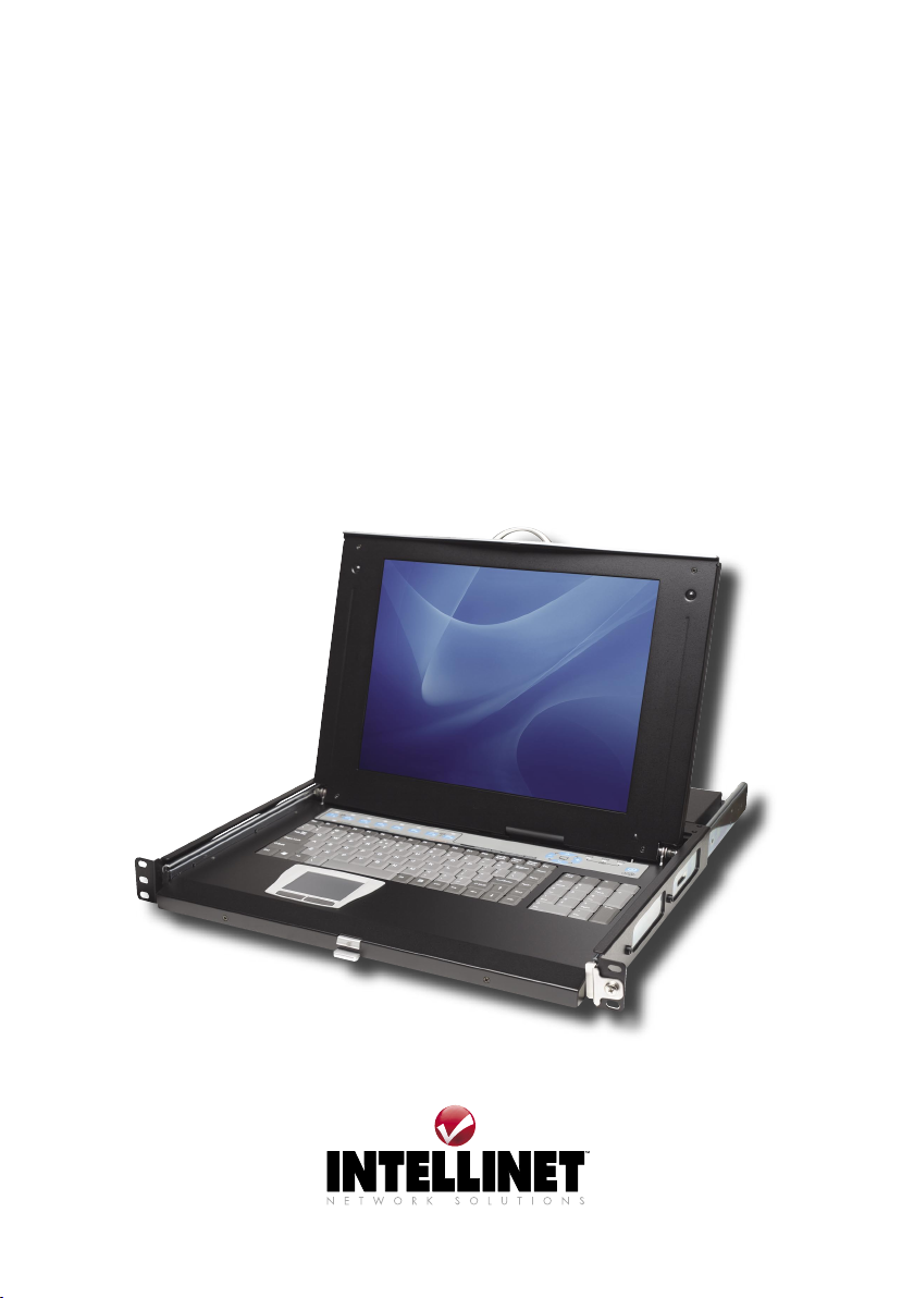
CONSOLE ASSEMBLY
Parts
Three-Section
Console:
A. 1U slide drawer with keyboard,
touchpad and
LCD monitor.
B. 1U or 2U KVM
Switch Module.
C. Rear bracket and
extension kit.
Rear Bracket and Extension Kit:
Each Rackmount Console KVM Switch
features a rear bracket and extension
kit, which includes two pieces of rear
brackets and two pieces of extensions.
The enclosed kit fits cabinet depths of
67.5 – 80.5 cm (26 5/8 – 31 5/8”), as
measured between the inside of a rack cabinet’s front
and rear uprights. As shown at right, the brackets and
extensions come in different lengths, and will vary
depending on the model.
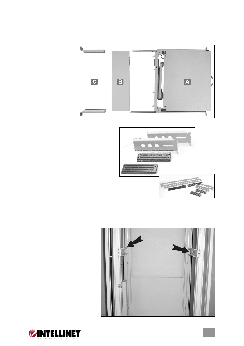
Assembly
1. Choose a proper position
for the rack drawer. Mount
the rear brackets (from the
rear bracket and extension
kit), and loosely fasten
them onto the rear vertical
uprights of the cabinet as
shown. Both will be
removed later.
3
3
Page 4

2. Remove the safety stopper
from the console drawer.
CAUTION: The safety
stopper is designed to prevent
the drawer from sliding out
during transportation: Once
it’s removed, the drawer may
slide out when tilted and
cause serious injury or damage.
3. Slide the console drawer
into the rack cabinet from
the front and insert the two
slide rails of the console
drawer into the sleeves of
the rear brackets.
4. Fasten the console drawer
to the outside of the front
vertical uprights using the
four screws provided. The
metal brackets (as indicated
by the far arrow) support the
rear side of the console.
NOTE: The image at right is
a front (console drawer-side)
view.
5. Remove both of the rear
brackets and slide the
console drawer out halfway
to balance its weight. At this
point, the front brackets hold
the console drawer. NOTE:
The image at right is a rear
(KVM switch module-side)
view.
4
4
Page 5

6. Attach the extensions (from the
rear bracket and extension
kit) to both sides of the KVM
switch module. NOTE: For a
2U module (Model 521871),
the extensions are mounted
to the lower half of the
module. In the inset at right,
you can also see that the wider lip is the top of the plastic extension.
7. The rear brackets, extensions and slide rails need to fit tightly. As shown
above-left, slide the rear brackets onto the extensions. Then, as shown above right, insert both sliding rails of the console drawer into the tight space
formed by the rear brackets and the extensions. Holding the KVM switch
module on both sides, push it in evenly.
8. Push the rear brackets all the
way in and fasten them
securely.
9. Slide the console drawer
out to gain access to the
connecting screws. Push the
KVM switch module evenly
toward the connector
attached to the console
drawer and lock both units
together by tightening the
screws indicated by the
arrows.
55
Page 6

10.
Make sure the CEN36 connectors are firmly mated
connector is secured firmly,
leaving a slight gap as
shown in the image at right.
11. Connect the power supply
to the power jack on the
KVM switch module to
complete the installation.
CEN36
CONSOLE INSTALLATION
Connecting
to a
Computer
Connecting
to a KVM
Switch
6
6
Page 7

Console Panel
The console panel of the Rackmount Console KVM Switch is located along
the top of the keyboard. The image below represents the console panel for
Models 521796 and 521871.
5
8
7
9
4
6
10
The image below represents the console panel for Models 523561 and 523578.
KVM Control and Status Indicators:
NOTE: This section is effective only when a KVM switch module is connected.
1. Computer Selection Pad — Press one of these buttons to select a computer.
For 16-port Model 521871, “1” – ”8” are for the lower row of eight ports and
“A” – ”H” are for the higher/upper row of eight ports. Port 1 and Port A share
the same button: If Port 1 is already selected, tap its button to select Port A.
If Port 1 is not selected, press and hold the “1” button on the console panel
for two seconds to select Port A.
2. Selected Computer Indicator — An indicator lights red when its corresponding
computer is selected.
3. Local Console in Operation — This lights green when a computer is accessed
through the console.
4. Remote Console in Operation — This lights green when a computer is accessed
by a remote keyboard/mouse/monitor set.
LCD Panel Controls:
5. LCD Panel Menu — These buttons bring up the on-screen display menu of
settings for the LCD panel.
6. LCD Panel Adjustment — These let you adjust the settings for the LCD panel.
7–9. Number lock, caps lock and scroll lock indicators, respectively.
10. LCD panel power switch.
77
Page 8

Replaceable Keyboard and Touchpad
Replaceable Keyboard (Models 523561 and 523578 only):
Triangular mark
The keyboard is replaceable for language change or maintenance. Tilt it up,
locate the mini-USB cable underneath the keyboard and gently unplug it. While
installing a keyboard, make sure that you extend just enough of the cable to
keep the keyboard flat inside the tray. NOTE: The triangular mark on the mini-
USB connector must face out, as shown in the magnified image above.
Replaceable Touchpad (Models 523561 and 523578 only):
The touchpad simulates a wheel mouse. The area of the touchpad to the right
side of the two small triangular
marks is the simulated “wheel,”
as shown at right.
To remove the touchpad, press
the tab underneath it upward
to release the latch, then slide
it outward till the touchpad
can be lifted up clear of the
notches, as shown below.
The touchpad is attached by
a piece of mini-USB cable.
88
Page 9

Triangular mark
To install the touchpad, extend just enough of the mini-USB cable and slide
the touchpad all the way in till you hear a click as it locks in position. NOTE:
The triangular mark on the mini-USB connector must face out, as shown in the
magnified image.
99
Page 10

LCD PANEL SPECIFICATIONS
15” LCD Panel 17” LCD Panel 19” LCD Panel
• Active display 304.1 x 228.1 337.92 x 270.336 376.32 x 301.056
area (mm)
• Pixel pitch (mm) 0.297 (H) 0.264 (per triad) 0.294 (H)
x 0.297 (V) x 0.264 x 0.294 (V)
• Resolution 1024 x 768 1280 x 1024 1280 x 1024
• Color pixel RGB vertical strip RGB vertical strip RGB vertical strip
arrangement
• Display mode normally white normally white normally white
• Brightness (cd/m^2) 250 (center) 260 (center) 250 (center)
• Contrast ratio 350:1 450:1 500:1
• Display color 16.2M (RGB 6-bits 16.2M (RGB 6-bits 16.7M
+ FRC data) + FRC data) (RGB 8-bits data)
• User control OSD control OSD control OSD control
(auto-saving) (auto-saving) (auto-saving)
• Input signal RGB analog, RGB analog, RGB analog,
H/V separate H/V separate H/V separate
• Plug and Play VESA VESA DDC 1/2B VESA DDC 1/2B VESA DDC 1/2B
• Power consumption 33 W max. 37 W max. 40 W max.
(normal operation/
typical)
• Viewing angle -70 – 70 (H; -80 – 80 (H); -85 – 85 (H);
(typical) -60 – 60 (V) -80 – 80 (V) -85 – 85 (V)
• Backlight unit 2 CCFLs edge-light 4 CCFLs edge-light 4 CCFLs edge-light
(top/bottom) (top/bottom) (top/bottom)
• Temperature, operating 0–50˚C (32–122°F) 0–50˚C (32–122°F) 0–50˚C (32–122°F)
• Temperature, storage -20–60°C (-4–140°F) -20–60°C (-4–140°F) -20–60°C (-4–140°F)
• Humidity, operating 0–95% relative 8–95% relative 8–95% relative
• Humidity, non-oper. 95% relative 95% relative 95% relative
• Power supply input Full range, Full range, Full range,
voltage 100–240 V AC 100–240 V AC 100–240 V AC
• Power supply input 47–63 Hz 47–63 Hz 47–63 Hz
frequency
• Approvals: CE, FCC for the product; UL, TUV, CE for the power supply
@ 60/70/75 Hz @ 60/70/75 Hz @ 60/70/75 Hz
NOTE: If part of the display is not clear, activate Auto Adjust for the LCD
monitor using the four LCD panel control buttons.
1010
Page 11

NOTES
1111
Page 12

www.intellinet-network.com
Are you completely satisfied with this product?
Please contact your INTELLINET NETWORK SOLUTIONS
with comments or questions.
All products mentioned are trademarks or registered trademarks of their respective owners.
Copyright © INTELLINET NETWORK
SOLUTIONS
™
dealer
 Loading...