

Page 1

Intel® NetStructure™
MPCHC5525 System Master
Processor Board IPMI Reference
Driver
User’s Manual
May 2004
Order Number: 301561-001
Page 2

INFORMATION IN THIS DOCUMENT IS PROVIDED IN CONNECTION WITH INTELR PRODUCTS. EXCEPT AS PROVIDED IN INTEL’S TERMS
AND CONDITIONS OF SALE FOR SUCH PRODUCTS, INTEL ASSUMES NO LIABILITY WHATSOEVER, AND INTEL DISCLAIMS ANY EXPRESS
OR IMPLIED WARRANTY RELATING TO SALE AND/OR USE OF INTEL PRODUCTS, INCLUDING LIABILITY OR WARRANTIES RELATING TO
FITNESS FOR A PARTICULAR PURPOSE, MERCHANTABILITY, OR INFRINGEMENT OF ANY PATENT, COPYRIGHT, OR OTHER
INTELLECTUAL PROPERTY RIGHT.
Intel Corporation may have patents or pending patent applications, trademarks, copyrights, or other intellectual property rights that relate to the
presented subject matter. The furnishing of documents and other materials and information does not provide any license, express or implied, by
estoppel or otherwise, to any such patents, trademarks, copyrights, or other intellectual property rights.
Intel products are not intended for use in medical, life saving, life sustaining, critical control or safety systems, or in nuclear facility applications.
Intel may make changes to specifications and product descriptions at any time, without notice.
Designers must not rely on the absence or characteristics of any features or instructions marked “reserved” or “undefined.” Intel reserves these for
future definition and shall have no responsibility whatsoever for conflicts or incompatibilities arising from future changes to them.
This User’s Manual as well as the software described in it is furnished under license and may only be used or copied in accordance with the terms of
the license. The information in this manual is furnished for informational use only, is subject to change without notice, and should not be construed as
a commitment by Intel Corporation. Intel Corporation assumes no responsibility or liability for any errors or inaccuracies that may appear in this
document or any software that may be provided in association with this document.
Except as permitted by such license, no part of this document may be reproduced, stored in a retrieval system, or transmitted in any form or by any
means without the express written consent of Intel Corporation.
Contact your local Intel sales office or your distributor to obtain the latest specifications and before placing your product order.
Copies of documents which have an ordering number and are referenced in this document, or other Intel literature may be obtained by calling
1-800-548-4725 or by visiting Intel's website at http://www.intel.com.
AnyPoint, AppChoice, BoardWatch, BunnyPeople, CablePort, Celeron, Chips, CT Media, Dialogic, DM3, EtherExpress, ETOX, FlashFile, i386, i486,
i960, iCOMP, InstantIP, Intel, Intel Centrino, Intel logo, Intel386, Intel486, Intel740, IntelDX2, IntelDX4, IntelSX2, Intel Create & Share, Intel GigaBlade,
Intel InBusiness, Intel Inside, Intel Inside logo, Intel NetBurst, Intel NetMerge, Intel NetStructure, Intel Play, Intel Play logo, Intel SingleDriver, Intel
SpeedStep, Intel StrataFlash, Intel TeamStation, Intel Xeon, Intel XScale, IPLink, Itanium, MCS, MMX, MMX logo, Optimizer logo, OverDrive,
Paragon, PC Dads, PC Parents, PDCharm, Pentium, Pentium II Xeon, Pentium III Xeon, Performance at Your Command, RemoteExpress, SmartDie,
Solutions960, Sound Mark, StorageExpress, The Computer Inside., The Journey Inside, TokenExpress, VoiceBrick, VTune, and Xircom are
trademarks or registered trademarks of Intel Corporation or its subsidiaries in the United States and other countries.
*Other names and brands may be claimed as the property of others.
Copyright © 2004, Intel Corporation
2 Intel® NetStructure™ MPCHC5525 System Mast er Process or Boar d IPMI Ref erence Driver User’s Manual
Page 3

Contents
Contents
1 Using This Guide.............................................................................................................................7
1.1 Terms and Definitions............. ...................................... ............................... ..................... ....7
1.2 Other Sources of Information................................................................................................8
2 IBMU Functionality .......................................... ..... ....... ....... ..... ....... .. .......... .. ....... ....... ..... ................9
2.1 Introduction...........................................................................................................................9
2.1.1 Purpose of IPMI....................... ...................................... ...................................... ....9
2.1.2 Who Gathers the Information?.................................................................................9
2.1.3 Where Is IPMI-Relevant Information Stored?........................................................10
2.1.4 Basic Communica tion Principles............... ............................... ..............................11
2.1.4.1 Boa r d s/De vices with IPMI Controller .......................................... ...........11
2.1.4.2 N on intellige nt D ev ic e s ... .. . .. ... .. .. .............. ... .. .. . .. .... . .. .. ... .. .. .............. . .. ...11
2.1.4.3 On-Board Temperat ure Sensor .......................... ...................................11
2.1.5 Requi re ments ........................................................................................................11
2.1.5.1 Boards/Devices with IPMI Controller and On-Board Sensors................11
2.1.5.2 N on intellige nt D ev ic e s ... .. . .. ... .. .. .............. ... .. .. . .. .... . .. .. ... .. .. .............. . .. ...12
2.1.6 Available Dr ivers............... ...................................... ............................... ................13
2.2 How Does Communicati on Work?........ ............................... ............................... ................13
2.2.1 Communication Within a Chassis..........................................................................14
2.2.1.1 Devices with IPMI Controller..................................................................15
2.2.1.2 N on intellige nt D ev ic e s ... .. . .. ... .. .. .............. ... .. .. . .. .... . .. .. ... .. .. .............. . .. ...15
2.2.1.3 On-Board Temperat ure Sensor .......................... ...................................16
2.2.2 Commu nication bet ween Chas sis..........................................................................16
3 Preparing Software for IPMI Usage...............................................................................................19
3.1 Action Plan.... ............................... ...................................... ...................................... ...........19
3.2 Notes on Writing Your Own IPMI Driver.............................................................................19
3.3 Sensor Data Records...... ........................ .............................. ............................... ..............20
3.3.1 Obtaining SDR Settings.........................................................................................20
3.4 Notes on Writing System Management Software..................................... ............ ....... .......20
3.4.1 Require men ts for Events .... ...................................................................................20
3.4.2 Checking CPU Board Sig n als........................................ ............................... .........21
3.4.2.1 Critical IRQ Status ................................................................................. 21
3.4.2.2 CPCI Signal .................. ...................................... ...................................21
3.4.2.3 Ej e cto r Swi tch.................................. ............................... .......................21
3.4.2.4 PO ST Cod e....... ................. ............................... .....................................22
3.4.3 Monitoring the IBMU..............................................................................................22
3.4.3.1 Self Test............................................. ...................................... ..............22
3.4.3.2 IPMI Controller Wat c h dog................................. .....................................22
4 Supported IPMI Commands
and BMC/PM Addresses23
4.1 Standard IPM I Comma n ds .......... ............................... ..................................... ...................23
4.2 Global IPMI Commands......................................................................................................23
4.2.1 System Interface Commands .......................... ...................................... ................23
4.2.2 Watchdog Com ma nds ...........................................................................................23
4.2.3 SEL Comm ands.....................................................................................................24
Intel® NetStructure™ MPCHC5525 System Master Processor Board IPMI Reference Driver User’s Manual 3
Page 4

Contents
4.2.4 SDR Comm ands....................................................................................................24
4.2.5 FRU Inventory Device Commands ................................................ ..... .. ..... ..... .. ....24
4.2.6 Sensor Device Commands ....................................................................................25
4.2.7 ICMB Bridge Commands.................................... .. ....... .......... .. ....... ....... ..... ....... ....25
4.3 Force-Specific Commands ...................................................... .......... .. ....... ..... .. .......... .. ....26
4.3.1 BMC/PMChangeRole ............................................................................................26
4.3.1.1 Request Data.........................................................................................26
4.3.1.2 Response Data......................................................................................26
4.3.2 FlashFileSystemClear............................................................................................27
4.3.2.1 Request Data.........................................................................................27
4.3.2.2 Response Data......................................................................................27
4.3.3 G et GeographicalAddress ......................................................................................27
4.3.3.1 Request Data.........................................................................................27
4.3.3.2 Response Data......................................................................................27
4.3.4 Get SDRR epos itoryCRC ........................................................................................27
4.3.4.1 Request Data.........................................................................................28
4.3.4.2 Response Data......................................................................................28
4.3.5 SetShadowRepositoryEnable................................................................................28
4.3.5.1 Request Data.........................................................................................28
4.3.5.2 Response Data......................................................................................28
4.4 BMC and PM Ad dresses .................................................................................................... 28
5 Customer Support......................................................................................................................... 31
5.1 Customer Support...............................................................................................................31
5.2 Technical Support and Return for Service Assistance .......................................................31
5.3 Sales Assistanc e............................ ...................................... .............................. ................31
Figures
1 Repositories of BMC and PMs ........................ ..... ....... ....... ....... ..... ....... ....... ..... ....... ....... ....... ....10
2 Required Parts for Communication with IPMI Devices and On-Board Sensors.........................12
3 Required Parts for Communication with Nonintelligent Devices ................................................12
4 Buses/Interfaces Provided by the IBMU.....................................................................................13
5 Communication within a Chassis................................................................................................14
6 Exam ple fo r PM wit h IPM I Controller..................................... .............................. .......................15
7 Example for Nonintelligent Devices... .. .......... .. ..... ....... ..... .. ....... ..... .. .......... .. ....... ..... .. .......... .. ....16
8 Example: On-Board Sensor........................................................................................................16
9 Intelligent Chassis Management Bus (ICMB).............................................................................17
10 Fan without IPMI Controller Monitored via ICMB .......................................................................17
11 Example for Nonintelligent Device via ICMB .............................................. ....... .. ....... .......... ......18
Tables
1 Ter ms and Def initions............................................. ............................... .......................................7
2 Refer e n ce Documents............................ ............................... ..................................... ..................8
3 Data in Repo sitories............ ............................... .............................. ..........................................10
4 Optional Global IPM I Comman ds.............................. ............................... .............................. ....23
5 Optional SEL Device Commands...............................................................................................24
6 Optional SDR Device Commands..............................................................................................24
7 Implemented Optional Sensor Device Commands.....................................................................25
8 Implemented Optional ICMB Bridge Commands........................................................................ 25
9 Address Mapping................................................................ ....... ....... ............ ............ ..................29
4 Intel® NetStructure™ MPCHC5525 Syst em Mast er Proc essor Board I PMI Refe rence Dr iver Us er’s Manua l
Page 5

Revision History
Date Revision Description
May 2004 001 Initial Release of this manual.
Contents
Intel® NetStructure™ MPCHC5525 System Master Processor Board IPMI Reference Driver User’s Manual 5
Page 6

Contents
6 Intel® NetStructure™ MPCHC5525 Syst em Mast er Proc essor Board I PMI Refe rence Dr iver Us er’s Manua l
Page 7

Using This G uide
Using This Guide 1
The Intel® NetStructure™ MPCHC5525 System Master Proces sor Board IPMI Reference Driv er
User’s Guide is intended for users qualified in electronics or electrical engineering. Users should
have a working understanding of PCI, CompactPCI*, telecommuni cations, and the IPMI
Specification V1.0 Rev. 1.1.
1.1 Terms and Definitions
T able 1. T erms and Definitions
Abbreviation Description
BIB Board Information Block
BMC Base Board Management Controller
CMD Command Code
CPU Central Processing Unit
CRC Cyclic Redundancy Code
ECC Error Correction Code
FRU Field Replaceable Unit
GPIO General Purpose I/O
2
C Intelligent I/O Controller
I
IBMU Intelligent Board Management Unit
ICMB Intelligent Chassis Management Bus
IPMB Intelligent Peripheral Management Bus
IPMI Intelligent Platform Management Interface
IRQ Interr upt Request
KCS Keyboard Controller Style
LSB Least Significant Byte
MSB Most Significant Byte
NetFn Network Function Code
NMI Nonmaskable Interrupt
OEM Original Equipment Manufacturer
PMC Peripheral Management Controller
POST Power-on Self Test
PSU Power Supply Unit
RAM Random Acce ss Memory
RTB Rear Transition Board
Intel® NetStructure™ MPCHC5525 System Master Processor Board IPMI Reference Driver User’s Guid e 7
Page 8

Using This G ui de
Table 1. Terms and Definitions
Abbreviation Description
SDR Sensor Data Record
SEL System Event Log
SMI System Mana gement Interface
1.2 Other Sources of Information
Table 2. Reference Documents
Document Can be found at
®
Intel
NetStructure™ MPCBL5525 System Master
Processor Board Technical Product Specifi cation
Intelligent Platform Management Interface Specification
v. 1.0 Rev. 1.1
Platform Management FRU Information Storage
Definition v1.0 Rev. 1.1
Intelligent Chassis Management Bus Bridge Specification
v1.0 Rev. 1.2
PICMG 2.9 R1.0 System Management Specification www.picmg.com
Force Computers* PENT/CPCI-735/736 Family
Refere nce Guide
Intel order number 301070
www.intel.com/design/servers/ipmi/spec_old.htm
developer.intel.com
www.intel.com/design/servers/ipmi/spec.htm
www.forcecomputers.com
8Intel
®
NetStructure™ MPCHC5525 Syst em Mas ter Processor Board IPMI Refere nce Dri ver User ’s Gui d e
Page 9

IBMU Funct i onality
IBMU Functionality 2
2.1 Introduction
The Intellig ent Board Management Unit (IBMU) equips the Intel® NetStructure™ MPCBL5525
board with Intelligent Platform Manageme nt Interface (IPMI) functionality as designed by Force
Computers*. IPMI is used fo r platform management.
IPMI is completely independent of the software running on the CPU board; it remains operative
even if the board soft ware has crash ed or the boa rd is not power ed. Due to thi s fact, IPMI is used to
log system status informa tio n .
IPMI functionality on the IBMU is based on the Intelligent Platform Management Standards V1.0
Rev. 1.1. In addition, the following optional features applying to the IPMI standard are offered:
• Buses th at allow in t er n al a n d external co m munica ti o n
• Optional IPMI commands
• BMC standby mode
The features of the IBMU allow platform management with devices with and without IPMI
controllers (nonintelligent devices). Both are handled differently in many aspects as explained in
the next sections.
2.1.1 Purpo se of IPMI
The purpose of IPMI is to gather information and control dev ices (e.g., fans). The types of
information tha t ca n be gat h er ed ar e:
• Inventory – Board type, manufacturer, se rial number, board revision etc.
• Sensor – Temperature, fan speeds, power supply unit (PSU) voltages.
The system management software can use the gathere d information to monito r system events and
trigger actions, i.e. perform so calle d platform management.
2.1.2 Who Gathers the Information?
In a system there are, for examp le, several CPU boards and fans. Each of them has inventory data
and sensors and can provide this inventory data and sensor data. To make communication within
your system easier, your system management software communicates with the CPU boards and
fans via one single IPMI controller on a CPU board. This IPMI controller wil l be the Base Board
Management Controller (BMC) a nd the other IPMI controllers on CPU boards or fans will be
Peripheral Management Controllers (PMs).
The BMC has a central function in gathering inventory and sensor-specific data, whereas the PMs
only provide data . Tha t is why only one BMC is allowed within one system chassis.
Intel® NetStructure™ MPCHC5525 System Master Processor Board IPMI Reference Driver User’s Guid e 9
Page 10
IBMU Funct i onality
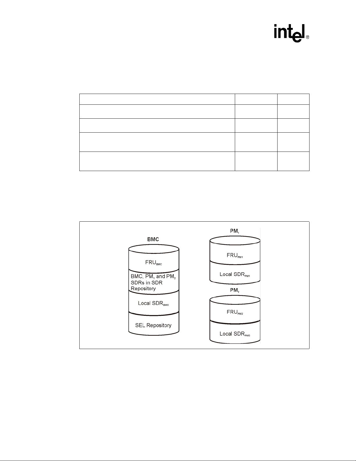
2.1.3 Where Is IPMI-Relevant Information Stored?
The following ta ble shows which informati on is stored in which reposi tory of a BMC/PM.
Table 3. Data in Repositories
Information Repository Available in
Inventor y info rm atio n on boa rd or de vice: Man uf act ur er I D, pro du ct ID et c.
Messages concerning events, such as abnormal voltages, out-of-range
temperatures etc.
Sensor data records (SDRs) of all sensors on a board. SDRs contain, for
example, thresh old values, conversion factors, and information on
whether events are generated.
SDRs of all sensors available in the entire system. At first, the SDR
repository of the BMC is empty, and the SDRs of all PMs must be copied
into the BMC’s SDR repository (will be explained later).
The IBMU provides approximately 100 Kbytes of flash memory for each repository.
The following figure shows the repositories available in IPMI controllers operated as BMC or PM
after the SDRs of the PMs were copied into the BMC’s SDR repository. Nonintelligent devices
provide none of the repositories.
Figure 1. Repositories of BMC and PMs
Field Replaceable
Unit (FRU)
System E vent Log
(SEL)
Local SDR PM and BMC
SDR BMC
PM and BMC
BMC
10 Intel® NetStructure™ MPCHC5525 Syst em Mas ter Processor Board IPMI Refere nce Dri ver User’s Guide
Page 11

2.1.4 Basic Comm unication Prin cip le s
The system management software communicates with the devices via the BMC. It can
communicate with:
• Boards/devic es with IPMI controller
• Boards/devices without IP MI controller (nonintelligent devices)
• On-board sensors
The following sections describe the basic communication procedure between the system
management software and the boards/devices given in the list above.
2.1.4.1 Boards/Devices with IPMI Controller
As seen in Figure 1, the BMC contains SDRs of all sensors in the system. If the temperature
threshold val ue is exce eded on a bo ard set as PM, the PM send s an event mes sage to the BMC. The
system management software can then trigger actions , for example, to increase the fan s pee d.
2.1.4.2 Nonintelligent Devices
For nonintelligent devices, there are no SDRs in the SDR repository of the BMC. Since
nonintelligent devices have no IPMI cont roller, they do not send event messages . For this reason,
the system management software must regula rly request sensor data (e.g., temperature) and check
whether the value has exceeded the normal range.
IBMU Funct i onality
2.1.4.3 On-Board Temperature Sensor
The on-board temperature sensor is connected to the IP MI controller; therefore, there is also an
SDR for this sensor in the BMC’ s SDR repository. If, for e xample, the t emperature thr es hold value
is exceeded, the IPMI controller sends an event message to the BMC. The system management
software can then trigger actions, for example, to increase the fan speed.
2.1.5 Requirements
2.1.5.1 Boards/Devices with IPMI Controller and On-Board Sensors
For communication between system management software and IPMI controller devices or onboard sensors, the following components are necessa ry:
• SDRs – Fo r each sensor at ta ch ed to an IPMI co n tr o l le r an SD R must be av ai lable
• IPMI driver for operating system
• Middleware
• System management softwa re
Intel® NetStructure™ MPCHC5525 System Master Processor Board IPMI Reference Driver User’s Guid e 11
Page 12

IBMU Funct i onality
Figure 2. Required Parts for Communication with IPMI Devices and On-Board S ensors
2.1.5.2 Nonintelligent Devices
For the communication between the sys tem management softwar e and nonintelligent devices the
following c omponents are necessa ry:
• IPMI driver for operating s ystem
• Middleware
• System management software
Figure 3. Required Pa rts for Com m unication with N oni nte l l ige nt D ev i ce s
12 Intel® NetStructure™ MPCHC5525 Syst em Mas ter Processor Board IPMI Refere nce Dri ver User’s Guide
Page 13

2.1.6 Available Drivers
IPMI drivers for the following operating systems are available:
• VxWorks*
• Windows 2000/NT*
• Solaris*
• MontaVista Linux*
These drivers include an application programming interface (API) to use IPMI commands. Please
see Appendix A for an API to use IPMI commands. Additional information regarding
implementing this software is available by contacting Force Computers
(www.forcecomputers.com).
2.2 How Does Communication Work?
Communication in this case mean s sendin g IPMI c ommands and recei ving a re sponse . All s tanda rd
IPMI commands are describe d in the IPMI Specification.
IBMU Funct i onality
System management software can communicate with:
• Devices with IPMI controller
• Nonintelligent devices
• On-board sensors
Communication is realized via buses and/or interfaces.
Figure 4. Buses/Interfaces Provided by the IBMU
Intel® NetStructure™ MPCHC5525 System Master Processor Board IPMI Reference Driver User’s Guid e 13
Page 14

IBMU Funct i onality
Whereas the Keyboar d Controller Style (KCS0) interface and the Intelligent Peripheral
Management Buses (IP MB) allow communication betwe en components within one chas sis, the
KCS0 interface and ICMB connect the devices of one chassis with anot her chassis. The I PMB and
ICMB buses a re IBMU powered and will be available even if the CPU board is not powered.
Note: On some boards the s ensors on the sensor bus are not powered by the IBMU. This means t hat if the
power supply is inter rupte d, the sensor s tatus at th e time of power suppl y interru pti on is logge d but
the current sensor value cannot be read. The current sensor value can be read as soon as the board
power is up again. For infor mation on whic h sensor on the sensor bus is not powered by th e IBMU,
refer to the CPU board’s TPS.
The followi ng sections describe which device is connected to which bus and give simple exa mples
for communication within a chassis and between two chassis.
2.2.1 Communication Within a Chassis
Communicati on within a chassis is possible via IP MB and the sensor bus which are both I²C-based
buses. Force Computers IBMU offers an IPMB0 and IPMB1 bus. The purpose of ea ch bus is as
follows:
• IPMB0 – Allows communication between BMC and IPMI control lers (PMs) on CPU boards.
• IPMB1 – Allows communication between:
— BMC and IPMI c ontroller of PMs like PSUs, fan trays, etc.
— BMC and devices in the system that are not equipped with an IPMI controller
• Sensor bus – A private bus that allows communication between the BMC and on-board
temperature sensor
Figure 5. Communication within a Chassis
®
The devices are connected to the IPMB1 via the Intel
Transition Board for the respective CPU board. The IPMB1 signals are routed from the IPMI
controller on the CPU board to the RTB via the backplane and are then available at an IPMB1
connector of the RTB. This IPMB1 connector is locat ed on-board the RTBs.
14 Intel® NetStructure™ MPCHC5525 Syst em Mas ter Processor Board IPMI Refere nce Dri ver User’s Guide
NetStruct ure™ MPRTM4848 Rear
Page 15

Note: After inst alling or removing a board und er hot-swap conditions , it is possible tha t nonintelligent
BMC
SEL
SDR
IPMB1 Int er fa c e
System
t
devices will block the IPMB bus. Therefore:
• If the device is powered by its own power s upply, turn off the device, then turn it on again.
• If the device is powered by the system’s power supply, turn off the whole system, then t urn on.
2.2.1.1 Devices with IPMI Controller
The following describes an easy event handling example for a fan module with IPMI controller.
The IPMI con troller on the CPU bo ard is the BMC and the one o n th e fan module the PM.
1. PM sends an event messag e to the BMC via IPMB1 saying that the fa n temperature has
exceeded the thre shold value defined in the SDR.
2. The BMC stores the message in the SEL repository and in an eve nt m es sage buffer.
3. The system management software regularly checks the SEL whether an event message was
sent with the IPMI command “Rea d SEL Entry”.
4. When the system management software gets the event message it triggers an action ac cording
to the defined error handling procedure, i.e. increase fan speed via the BMC and fan regis ter.
Figure 6. Example for PM with IPMI Controller
IBMU Funct i onality
PM
IPMI
Controller
of Fan
1
To make this possible the SDR of each sensor connected to an IPMI controller has to be written
into the S DR repository of the BMC on the CPU board.
2.2.1.2 Nonintelligent Devices
Suppose another fan module does not have an IPMI controller. In this case, it cannot send event
messages to the IPMI controller on the CPU board. Therefore, the system management softwa re
has to read the temperature of the fan module regularl y using the IPMI command “Master Write-
2
Read I
C” and control it accordingly .
1. The system management software sends the IPMI command “Master W r ite-Read I
BMC via IPMB1.
2. The BMC reads the temperat ure from the sensor on the fan.
3. The BMC forwards the temperature value to the system management software.
Buffer
Event Message
Buffer
2
Managemen
Software
3
44
2
C” to the
4. If the temperature is too high, the system management software can change the fan speed via
the IPMI command “Master Write-Read I
Intel® NetStructure™ MPCHC5525 System Master Processor Board IPMI Reference Driver User’s Guid e 15
2
C” and the fan speed register.
Page 16

IBMU Funct i onality
Figure 7. Example for Nonintelligent Devices
2.2.1.3 On-Board Temperature Sensor
To read out the actua l temperature value from the on-board sensor , the procedure is as follows:
1. The system management s oftware sends the IPMI command “Get Sensor Reading” to the
BMC, the BMC reads the value from the on-board sensor and sends it to the system
management software.
2. The system management software compares the read value with a threshold value.
3. If the tempera tu re is too high, the system management software can, for exam p l e, initiate a
switch board or an alarm module to switch off the board by deactivating the BD_SEL# signal.
Figure 8. Example: On-B oard Sensor
2.2.2 Communication between Chassis
Communicati on betwe en se veral chass is is p os sible wit h t he I CMB, whic h is an RS- 485-bas ed bus .
It connects the BMCs of two or more chassis. You can connect up to 42 chassis, according to the
ICMB Specification v1.0 Rev. 1.2. Refer to this specif ication for information on maximum cable
length.
The chassis are connected via the CPU boards’ RTBs. The ICMB connector is typically located on
the R T B’s front panel. See t he Intel
for further reference.
16 Intel® NetStructure™ MPCHC5525 Syst em Mas ter Processor Board IPMI Refere nce Dri ver User’s Guide
®
NetS tructu r e™ M PRTM4808 Technical Pr od uct Spe ci ficat ion
Page 17

Figure 9. Intelligent Chassis Management Bus (ICMB)
The connection via I CMB is use ful for maintenance purposes. If, for example, the CPU board in
one chassis hangs, the BMC in the o t her chassis can read the log file of the af f ected BMC via
ICMB.
IBMU Funct i onality
Another applica tion is the monitoring and controlling of noni ntelligent devices. If the CPU board
the BMC is locat ed on hangs or is i n stand-by m ode, t he BMC in anot her cha ssis can req uest sensor
data of the noninte lligent device via ICMB and the command “Master Write-Read I
The following section provides a simple communication example. The example supposes that a
nonintelligent fan module located in chassis 1 and connected via IPMB1 to the BMC in chassis 1
(BMC1) is monitored and managed by the BMC in chassis 2 (BMC2).
Figure 10. Fan without IPMI Co ntroller Monitored via ICMB
2
C”.
The communication procedure is as follows:
Intel® NetStructure™ MPCHC5525 System Master Processor Board IPMI Reference Driver User’s Guid e 17
Page 18

IBMU Funct i onality
1. The system management software residing on the CPU board in chassis 2 sends an ICMB
messa g e to the BMC2. This ICMB message contains the ICM B h eader information and the
IPMI command “Master Write-Read I
2
C” with which the fan sensor data is requested.
2. The BMC2 sends the ICMB message to the BMC1 via ICMB.
3. BMC1 extracts the IPMI command “Master Write-Read I2C” from the ICMB me ssage.
4. BMC1 reads the sensor temperature on the fan module via the command “Master Write-Read
2
I
C” and sensor registers.
5. BMC1 adds an ICMB header to the sensor result and sends the ICMB message via ICMB and
BMC2 to the system manag em ent softwa re.
Figure 11. Example for Nonintelligent Device via ICMB
18 Intel® NetStructure™ MPCHC5525 Syst em Mas ter Processor Board IPMI Refere nce Dri ver User’s Guide
Page 19

Preparing Software for IPMI Usage
Preparing Software for IPMI Usage 3
3.1 Action Plan
Before being able to u se IPMI th e followi ng ste ps ar e requir ed and wil l be descri bed in th is chapt er.
3.2 Notes on Writing Your Own IPMI Driver
The Intel® NetStructure ™ MPCBL5525 offers IPMI drivers for seve ral operating systems. For
information about de signi ng your own IPMI dri ver , refer to t he Intell igent Board Management Unit
Reference Guide (PN217328), available by contacting Force Computers.
The interface type used by the IBMU is the Keyboard Controller Style (KCS) interface. For the
communication between the IPMI controller and the system management software, the KCS0
interface is used. There are also the KCS1 and KCS2 interfaces: KCS 1 can be used to enable ECC
error logging in the SEL via the operating system, and KCS2 is used for the BIOS POST codes.
The KCS0 interface can be used in polle d or in interrupt-driven mode. The default mo de is polled,
i.e. the application management software regularly read s th e KCS0 r egister to find out whether
data has arrive d or the s tate has chang ed. Inte rrupt-dri ven mod e means tha t the IP MI control ler s ets
an interrupt in case data has arrived or the state has changed so that the IPMI driver is informed
automatically.
Intel® NetStructure™ MPCHC5525 System Master Processor Board IPMI Reference Driver User’s Guid e 19
Page 20

Preparing Software for IPMI Usage
3.3 Sensor Data Records
For each sensor attac hed to an IPMI controller in a system you need SDR s. SDRs for s ensors on
Force CPU boards are provided by Force Computers. SDRs for senso r s on third-party products
must be obtained by the respective manufacturer.
3.3.1 Obtaining SDR Set tings
T o obt ain SD R settin gs ( threshold s, whe ther thre shol ds can be changed, whethe r a se nsor genera tes
events etc.), the default way is to write a function using the IPMI command “Get Device SDR” via
your operating system IPMI driver API. To obtain only the threshold values, the default way is to
write a function using the IPMI command “Ge t Sensor Threshol d” via your operat ing system IPMI
driver API.
Note: On some b oards, the th resholds for the board temperat ure sensor can be changed. For these boards,
the upper and lower thres hold values are by default set to the sensor’ s mini mum/maximum readi ng
values so that events fr om the board temperature sensor are not likely to occur. To generate events,
change the thres holds value s. Ke ep in min d th at the mea sured sensor va lu e depe nds on t he s ystem’s
components and their location. For information on where the board temper ature is measured on
your CPU board, refer to the CPU board’s TPS.
To obtain SDR information without having to write a function, go to http: //www.intel.com/design/
servers/ipmi/tools.htm for the Intel IPMI Tool. See the IPMI Specification for more information.
3.4 Notes on W r iting System Management Software
For creating your own s yst em management software you can use all IPMI commands marked as
mandatory in the IPMI Specification. For information regarding Force-s pecific OEM IPMI
commands, see the Intelligent Boar d Management Unit Reference Guide (PN217328) available by
contacting Force Computers.
With your ma na g e me n t sof tw a re an d Forc e -specific OE M IP MI co mmands, you:
• Can check statu s o f board s ensor s (physic al sensors s uch as t emper ature o r vol tage sen sor s and
discrete s ensors). In the following only the reading values of the discrete sensors are described.
• Can obtain IBMU self-test results.
• Have to check whether the IPMI controller watchdog has reset th e IPMI firmware .
3.4.1 Requirements for Even ts
By default, the BMC only receives event messages from sensors attached to the BMC itself. To
make PMs sen d event me ssages to th e BM C, you need to d ef ine the event rece iver, the BMC, via
the IPMI co m mand “Set Eve n t Re ceiver ”.
20 Intel® NetStructure™ MPCHC5525 Syst em Mas ter Processor Board IPMI Refere nce Dri ver User’s Guide
Page 21

3.4.2 Checkin g CP U Boar d Si gn als
The IBMU is equipped with several discrete sensors used to check the assertion or dea ssertion of
CPU board signals. Aft er an asserti on or deass ertion of such a signa l, the IPMI contro ller gen erates
event messages. For further information on event messages, refer to tables 17-5 and 19-1 of the
IPMI Specification 1.0.
Set as PM, the IPMI controller sends these messages to the BMC in the system. The BMC saves
the messages in the S EL and in the event message buffer.
Note: In com par ison to the event message buffer, the SEL keeps al l events, even if the IPMI controller is
turned off. T h erefore, read the events from the SEL with the IPMI command “Get SEL Entry” and
not from the event message buffer.
Set as BMC, th e IPMI controll er simply sav es the event mes sages in the SEL and in the event
message buffer.
The following subsections describe the discrete sensors that generate event messages which can be r ead by the system management software.
Note: Usually the s ens or type is used to find out which s ens or has sent an event and which signals were
asserted. Since all se nsors che cking the CPU board sign als a re of the same s ensor type, you have to
use the sensor number to distinguish between the sensors.
Preparing Software for IPMI Usage
3.4.2.1 Critical IRQ Status
This sensor reads the following signals which have IRQ capability:
• PCI_RESET
If asserted, signals that all devices attached to PCI buses are reset.
• NMI
• SMI
• IPMB1_ALERT
If asserted, signals that a sensor on IPMB 1 has rea ched a cri tica l status .
3.4.2.2 CPCI Signal
This sensor reads two PCI-relevant signals, CPCI_ENUM and CPCI_BD_SEL. CPCI_ENUM is
asserted, if a board is about to be removed from the system. CPCI_BD_SEL is asserted, if a board
was fully plugged into the system and is running.
3.4.2.3 Ejector Switch
This sensor reads the LOCAL_ENUM signal. It is asserted when the lower front panel handle on
the board containing the IPMI module was opened.
Intel® NetStructure™ MPCHC5525 System Master Processor Board IPMI Reference Driver User’s Guid e 21
Page 22

Preparing Software for IPMI Usage
3.4.2.4 POST Code
This sensor allows you to read the board’ s POST code with the IPMI command “Get Sensor
Reading”.
Note: This sensor does not generate event messages.
3.4.3 Monitoring the IBMU
The Intel NetS tructure MPCBL5525 System Master Board provide s the possibility for the system
management software to obtain information on a possible IBMU problem source (missing S DRs,
memory error, or inaccessible buses). Furthermore, the IBMU guarantees uninterrupted system
operation becau se the IPMI controller watchdog resets the firmware if the firmware hangs.
3.4.3.1 Self Test
The IBMU provides a self test that is run every tim e it is restarte d, i.e. after plugging in the board
containing the IBMU or after a crash. The self test result can be read with the IPMI command “Get
Self Test Results”.
3.4.3.2 IPMI Controller Watchdog
The IPMI controller watchdog constantly monitors the IPMI firmware. If it detects a firmware
crash, it automatic ally issues a reset of the IPMI controller. The board the IPMI controller is
located on will NOT be reset.
If the BMC is res et and a PM sends a message to the BMC during this reset, the message is lost.
Your system management software therefor e must send the command “Re-arm Sensor Events” to
the PM. Then this PM will send th e event as long as the critical situation persists.
Note: If a PM is reset, your system management applica tion must realize that a re se t has occurred and
initialize the IPMI c ontroller. You need to take this into consideration when programming your
system manageme nt application. Check e.g. the system time which is 0.00 after a reset.
22 Intel® NetStructure™ MPCHC5525 Syst em Mas ter Processor Board IPMI Refere nce Dri ver User’s Guide
Page 23

Supported IPMI Commands and BMC/PM Addresses
Supported IPMI Commands
and BMC/PM Addresses 4
4.1 Standard IPMI Commands
This section pr ovides information on which IPMI comm ands are supported. All co mmand s a r e
uniquely identified by:
• Network function cod e (Net F n) – Specifies functional category of a command
• Command code (CMD) – Byte which specifies the operatio n
The IPMI Specification defines several software channels which allow communication. The
channel number must always be incl uded in Send Message commands (for further information
refer to the IPMI Specification). IPMB0 is addressed via software channel 0 and IPMB1 via
channel 1.
4.2 Glob a l IPMI Com mands
All commands in this cat egory defined as mandatory by the IPMI S pecification are implemented.
In addition, the following option al commands are availab le.
Table 4. Optional Global IPMI Commands
Command NetFn CMD
Cold Reset App 02
EnableMessageChannelReceive App 32
GetDeviceGUID
ReadEventMessageBuffer App 35
1. Only available on boards produced after 03/01/2003. You can read the production date from
the Product Info Area of the FRU repository.
All implemente d comma nds can be used in every operation mode.
4.2.1 System Interface Commands
All commands in this cat egory defined as mandatory by the IPMI specification are impl emented.
All commands can be used in every operation mode.
4.2.2 Watchdog Commands
1
App 08
16
16
16
16
All commands in this cat egory defined as mandatory by the IPMI specification are impl emented.
All commands can be used in every operation mode.
Intel® NetStructure™ MPCHC5525 System Master Processor Board IPMI Reference Driver User’s Guid e 23
Page 24

Supported IPMI Comma n ds and BMC/P M Ad dresses
4.2.3 SEL Commands
All commands i n th is ca tegory def ined a s manda tory by the IPMI spec ifica tion a re imple mented. In
addition, the following optional commands are available.
Note: SEL commands can only be used in BMC mode.
Table 5. Optional SEL Device Commands
Command NetFn CMD
Get SEL Allocation Info Storage 41
Reserv e S EL Storage 42
Add SEL Entry Storage 44
Partial Add SEL Entry Storage 45
Delete SEL Entry Storage 46
4.2.4 SDR Commands
All commands i n th is ca tegory def ined a s manda tory by the IPMI spec ifica tion a re imple mented. In
addition, the following optional commands are available.
16
16
16
16
16
Table 6. Optional SDR Device Commands
Command NetFn CMD
Get SDR Allocation Info Storage 20
Add SDR Storage 24
Partial Add SDR Storage 25
Delete SDR Storage 26
Get SDR Repository Time Storage 28
Set SDR Repository Time Storage 29
All commands can be used in eve r y operation mode.
4.2.5 FRU Inventory Device Commands
All commands in this category defined as man datory by the IPMI Specific ation are implemente d.
The commands can be used in every operation mode.
The FRU information returne d by the IPMI command “Read FRU Inventory Data” is compatibl e
with the Platform Management FRU information Storage Definition v 1.0.
The size of the complete FR U record consisting of:
• Internal Use Area
• Board Info Area
• Product Info Area
• Multi Record Area
16
16
16
16
16
16
is limited to 1024 bytes.
24 Intel® NetStructure™ MPCHC5525 Syst em Mas ter Processor Board IPMI Refere nce Dri ver User’s Guide
Page 25

Supported IPMI Commands and BMC/PM Addresses
4.2.6 Sensor Device Commands
All comm an ds in thi s ca tego ry d efi ned as man dat or y b y th e IP MI spec ifi ca tio n ar e i mp leme nte d. In
addition, the following optional commands are available.
Table 7. Implemented Optional Sensor Device Commands
Command NetFn CMD
Get Device SDR Info S/E 20
Get Device SDR S/E 21
Reserve Device SDR Repository S/E 22
Get Sens or Re ad ing Fact ors S/E 23
Set Sensor Hysteresis S/E 24
Get Sensor Hysteresis S/E 25
Set Sensor Threshold S/E 26
Get Sensor Threshold S/E 27
Set Sensor Event Enable S/E 28
Get Sensor Event Enable S/E 29
Re-arm Sensor Events S/E 2A
Get Sensor Readin g S/E 2 D
Set Sensor Type S/E 2E
Get Sens or Type S/ E 2F
Set Event Receiver S/E 00
Get Event Receiver S/E 01
Platform Event S/E 02
All commands can be used in every operation mode.
16
16
16
16
16
16
16
16
16
16
16
16
16
16
16
16
16
4.2.7 ICMB Bridge Commands
All comm an ds in thi s ca tego ry d efi ned as man dat or y b y th e IP MI spec ifi ca tio n ar e i mp leme nte d. In
addition, the following optional commands are available.
Table 8. Implemented Optional ICMB Bridge Commands (Sheet 1 of 2)
Command NetFn CMD
Get Bridge State B ri dge 00
Set Bridge State Bridge 01
Get ICMB Address Bridge 02
Set ICMB Address Bridge 03
Set Proxy Address Bridge 04
Get Bridge Statist ic s Bridge 05
Clear Bridge Statistics Bridge 08
Get Proxy Addr e s s Bridge 0 9
Intel® NetStructure™ MPCHC5525 System Master Processor Board IPMI Reference Driver User’s Guid e 25
16
16
16
16
16
16
16
16
Page 26

Supported IPMI Comma n ds and BMC/P M Ad dresses
Table 8. Implemented Optional ICMB Bridge Commands (Sheet 2 of 2)
Command NetFn CMD
Get ICMB Connector Info Bridge 0A
Prepare for Discovery Bridge 10
Get Addresses Bridge 11
Set Discovered Bridge 12
Bridge Request Bridge 20
Bridge Me ssage Bridge 21
Get Bridge Event Count Bridge 30
Set Event Destination Bridge 31
Set Event Reception State Bridge 32
Send ICMB Event Message Bridge 33
Get Even t Destination Bridg e 34
Get Even t Recept ion State Bridge 35
4.3 Force-Specific Commands
The Force Computers IPMI firm ware supports several commands that are not defined in the IPMI
specificat ion but are introduced by Force Computers. For more information rega rding Forcespecific OEM IPMI implementations, see the Intelligent Boar d Man agement Unit Refe r ence Guide
(PN217328), available by contacting Force Computers.
16
16
16
16
16
16
16
16
16
16
16
16
4.3.1 BMC/PMChangeRole
This command is used to set the operation mo de of the IPMI controller (BMC, PM or BMC standby). In BMC stand-by mode, a mode pr ovided by Force Computers, the IPMI controller is PM but
can manipulat e the system event log (SEL) and sensor data repositories (SDR) like a BMC.
4.3.1.1 Request Data
Byte Data Field
Role
1
4.3.1.2 Response Data
Byte Data Field
1 Completion Code
0: BMC
1: BMC stand-by
2: PM
26 Intel® NetStructure™ MPCHC5525 Syst em Mas ter Processor Board IPMI Refere nce Dri ver User’s Guide
Page 27

Supported IPMI Commands and BMC/PM Addresses
4.3.2 FlashFileSystemClear
This command is used to delete all the SDR, FRU and SEL repository and to upd ate the FRU data.
4.3.2.1 Request Data
Byte Data Field
--
4.3.2.2 Response Data
Byte Data Field
1 Completion Code
4.3.3 GetGeographicalAddress
This command is used to obtain the geographi cal address of the slot into which the board with the
IPMI controller is plugged in and the IPMI controller’s I
every operation mode.
4.3.3.1 Request Data
None
4.3.3.2 Response Data
Byte Data Field
1 Completion Code
2 Geographical address
3 I²C addr ess of the IPMI controller on the IPMB(s) bus(es) in its current r ole
4 I²C address of the IPMI controller on the IPMB(s) bus(es) in PM role
If the IPMI controller acts as PM or BMC stand-by, the values in byte s 3 and 4 are equal. If the
IPMI controller acts as BMC, the value in byte 3 is 20
the BMC would have if he acts as PM.
4.3.4 GetSDRRepositoryCRC
This command is used to obtain the Cyc lic Redundancy Code (C RC) of the SDR repository. It can
be used in high-availability configurations to verify that th e SDR repository of the IPMI controller
in BMC active mode and that of the IPMI controller in BMC stand-by mode are identical.
2
C address. This command can be used in
and the value in byt e 4 is the I2C address
16
This command can be used in every operation mode.
Intel® NetStructure™ MPCHC5525 System Master Processor Board IPMI Reference Driver User’s Guid e 27
Page 28

Supported IPMI Comma n ds and BMC/P M Ad dresses
4.3.4.1 Request Data
Byte Data Fi eld
--
4.3.4.2 Response Data
Byte Data Fi eld
1 Completion Code
2 Record co unt LSB
3 Record count MSB
4 CRC16 LSB
5 CRC16 MSB
4.3.5 SetShadowRepositoryEnable
This command is used to enable or disabl e the access to the shadow repos itory of an IPMI
controller in BMC stand-by mode.
Note: This command can onl y be used if IPMI controller is in BMC stand-by mode. If the IPMI
controller is not in BMC stand-by mode, “invalid command” is returned.
4.3.5.1 Request Data
Byte Data Field
1
4.3.5.2 Response Data
Byte Data Fi eld
1 Completion Code
4.4 BMC and PM Addresses
To be able to send messages to other IPMI controllers (PMs) with your system management
software, you need the IPMI controller’s I
If the IPMI controller acts as BMC, the I
2
C address.
2
C address is 2016.
Access
0: Disabled
1: Enabled
If the IPMI controller is set to PM, it depends on the geographical address of the boar d in the
system. Refer to the system’s backplane descript ion to find the geographical addresses or use the
Force-specific IPMI command GetGeographica lAddress. The mapping of geographical and I
28 Intel® NetStructure™ MPCHC5525 Syst em Mas ter Processor Board IPMI Refere nce Dri ver User’s Guide
2
C
Page 29

addresses is defined in the PICMG 2.9 Specification and is also shown in the table that follows.
The IPMI controll er of a board which has the geographical address 4 in a system, for example, can
be addressed via I
2
C address B616.
Table 9. Address Mapping
Geograph ica l A ddre ss I²C Addres s
0 Disabled
1B0
2B2
3B4
4B6
5B8
6BA
7BC
8BE
9C0
10 C4
11 C6
12 C8
13 CA
14 CC
15 CE
16 D0
17 D2
18 D4
19 D6
20 D8
21 DA
22 DC
23 DE
24 E0
25 E2
26 E4
27 E6
28 E8
29 EA
30 EC
31 Disabled
Supported IPMI Commands and BMC/PM Addresses
16
16
16
16
16
16
16
16
16
16
16
16
16
16
16
16
16
16
16
16
16
16
16
16
16
16
16
16
16
16
Intel® NetStructure™ MPCHC5525 System Master Processor Board IPMI Reference Driver User’s Guid e 29
Page 30

Supported IPMI Comma n ds and BMC/P M Ad dresses
30 Intel® NetStructure™ MPCHC5525 Syst em Mas ter Processor Board IPMI Refere nce Dri ver User’s Guide
Page 31

Customer Support
Customer Support 5
5.1 Customer Support
This chapter offers technical and sales assistance information for this product. Information on
returning an Intel
®
NetStructure™ product for service is in the following chapter.
5.2 Technical Support and Return for Service Assistance
For all product returns and support issues, please contact your Intel product distributor or Intel
Sales Rep r esentative for specific information.
5.3 Sales Assistance
If you have a sales question, please contac t your local Intel NetS tructure Sales Representative or
the Regional Sales Office for your area. Address, telephone and fax numbers, and additional
information is available at Intel's website loc ated at:
http://www.intel.com/network/csp/sales/
Intel Corpor at ion
Telephone (in U.S.) 1-800-755-4444
Telephone (Outsi de U.S.) 1-973-993-3030
FAX 1-973-967-8780
Intel® NetStructure™ MPCHC5525 System Master Processor Board IPMI Reference Driver User’s Guide 31
Page 32

Customer Support
32 Intel® NetStructure™ MPCHC5525 Syst em Mas ter Processor Board IPMI Refere nce Dri ver User’s Guide
 Loading...