

Page 1

Rev: 0.1, October,2012
User’s Manual
ITX-IC2M1026S
ITX-IC8M1026Series
Motherboard
Intel Atom Series Martherboard
Page 2

Disclaimer
The intellectual property of this manual belongs to our company. The ownership of all of the
products, including accessories and software etc. belong to our company. No one is permitted to
copy, change, or translate without our written permission.
We compiled this manual based on our careful attitude, but we can not guarantee the accuracy
of the contents. This manual is purely technical documentation, without any hint or other
meanings, and we won't commit users' misunderstanding of the typesetting error.
Our products are in continuous improvement and updating, Therefore, we retain the right that
we won't give notice to the users in future.
Copyright
All of the trademark in this manual belong to their own registered company.
All of the products name is only for identication, its title belongs to its manufacturer or brand
owner.
Page 3

Chapter 1 Introduction
............................................................................. 4
1.1
Package Checklist
....................................................................................................4
1.2
Specications
..........................................................................................................5
1.3
Mainboard Layout
....................................................................................................6
1.4
Connecting Rear Panel I/O Devices
............................................................................7
Chapter 2 Hardware Setup
..........................................................................8
2.1 Installing the I/O rear panel........................................................................................8
2.2 Installing motherboard to chassis.................................................................................8
2.3 Installing Memory
Module
............................................................................................9
2.4
Connecting Peripheral Devices
.................................................................................10
2.4.1 Serial ATA
Connectors
........................................................................................................10
2.4.2 MPCIE
slot
.........................................................................................................................10
Chapter 3 Jumpers & Headers Setup
..........................................................11
3.1
Checking Jumper Settings
.......................................................................................11
3.2 Clear CMOS Header Setting .......................................................................................11
3.3 Jumpers Setting.......................................................................................................12
3.4 Front panel pin interface...........................................................................................13
3.5 J
LVDS1
pin interface..................................................................................................13
3.6
LPT
pin interface......................................................................................................14
3.7 Front
VGA
pin interface..............................................................................................15
3.8
GPIO
pin interface.....................................................................................................15
3.9
JINVERT1
pin interface ............................................................................................16
3.10
IRDA
pin interface ..................................................................................................16
3.11 F
USB1/2/3
expansion interface.................................................................................17
3.12
Front Panel Audio output
interface..........................................................................17
3.13 S/PDIF
output
interface..........................................................................................18
3.14 COM
Connectors
...................................................................................................18
3.15 KM1
(PS/2interface adapter
)
................................................................................19
3.16 SATA1/2_PWR
(SATA
Power interface)and
J14(DC
Power interface)..........................19
Chapter 4 BIOS Setup Utility
.....................................................................20
4.1
About BIOS Setup......
.............................................................................................20
4.2 BIOS
Setup
..........................................................................................................20
4.2.1
To run
BIOS
setup
..........................................................................................................20
4.2.2
Control Keys
................................................................................................................22
4.2.3
Main
...........................................................................................................................23
4.2.4
Advanced
....................................................................................................................23
4.2.5
Chipset
.....................................................................................................................29
4.2.6
Boot
............................................................................................................................31
4.2.7
Secunity
.............................................................................................................32
4.2.8
Exit
................................................................................................................................33
Chapter 5 Driver Installation
....................................................................34
Appendix:
Toxic and hazardous substances or elements logo
......................35
Table of Contents
Page 4

- 4 -
Intel Atom Series User’s Manual
Chapter 1 Introduction
1.1 Package Checklist
Thank you for choosing our products.
Before using your product, please make sure your packaging is complete, if there have
damage or you nd any shortage, please contact your supplier as soon as possible.
• Motherboard x 1
• COM Data Cable x 1
• SATA Data Cable x 1
• SATA Pwer Cable x 1
• DC Extension Cable x 1
• User's Manual x 1
• Driver x 1
The above accessories and speci cations are only for reference, we reserve the modify rights.
Page 5

- 5 -
Intel Atom Series User’s Manual
1.2 Motherboard specications
CPU - Intel®“Atom”D2550/N2800 ( optional
)
Chipet - Intel Atom + NM10 chipets
Memory
- 1x204-pin DDRIII SO-DIMM sockets
- Support for DDRIII SO-DIMM Memory
- Supporting up to 4GB of system memory
Expansion slots - 1 x Mini PCIE slot
Rear Panel I/O
- 1 x J1 interface(DC power
)
- 1 x VGA interface
- 1 x HDMI interface
- 2 x RJ45 interface
- 2 x USB 2.0 interface,Backward compatible with USB 1.1
- 2 x Audio interface(Line Out/Mic In)
Internal
Connectors
- 1 x 4-pin DC power socket
- 3 x USB pin,Connecting to 6 Additional External USB 2.0
- 6 x COM(9pin Charged way,5V/12V optional
)
- 1 x LPT pin
- 1 x Front Audio pin
- 1 x IRDA pin
- 1 x SPDIF Outpin
- 1 x LVDS pin( Supporting Double show mode by VGA
)
- 1 x JVGA pin
- 1 x GPIO pin
- 2 x FAN pin
- 1 x Front panel pin
- 2 x SATAII conection interface
BIOS/Power Management
- AMI BIOS
- 16MBit SPI BIOS
- Supporting Advanced Power Management ACPI
- CPU Temperature, Fan speed, System Voltage Monitoring
Audio
- Onboard 2 HD Audio Codec
-
Front
Audio
Interface , providing stereo MIC port on front pane
l
LAN - 2 x onboard 10/100/1000Mbps compatible LAN
Form Facto - Mini-ITX(170mm * 170mm)
Working Environment
- Working Temperature :-10~60°C
- Working Moisture:5%~95% No Frost
Page 6

- 6 -
Intel Atom Series User’s Manual
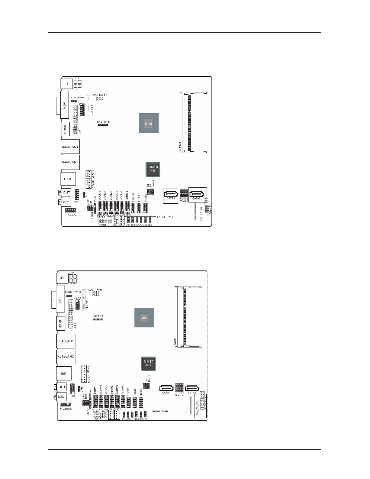
1.3 Motherboard Layout
(
This picture is only for reference
)
Page 7

- 7 -
Intel Atom Series User’s Manual
• J1 :
DC
Power interface
。
• VGA : Connecting to a monitor's VGA input
。
• HDMI :Connecting to a monitor's HDMI input.
• USB :
USB
Connecting Interface
。
• LAN:The LAN port allows the motherboard to connect to a local area network by means
of a network hub.
• AUDIO :
Line-out (Front Left/Right Jack, Lime): This jack is used to connect to the front left and
right channel speakers of the audio system.
Mic-in (Pink): This jack is used to connect an external microphone.
1.4 Connecting Rear Panel I/O Devices
(
This picture is only for reference
)
Page 8
- 8 -
Intel Atom Series User’s Manual
Chapter 2 Hardware Setup
2.1
Installing
I/O Panel
It can block the transmission of electric RF, protect the internal components, and promote
airow after installing this panel. Before installing motherboard, you need to install this panel. If
required, you should uninstall the optional panel rst.
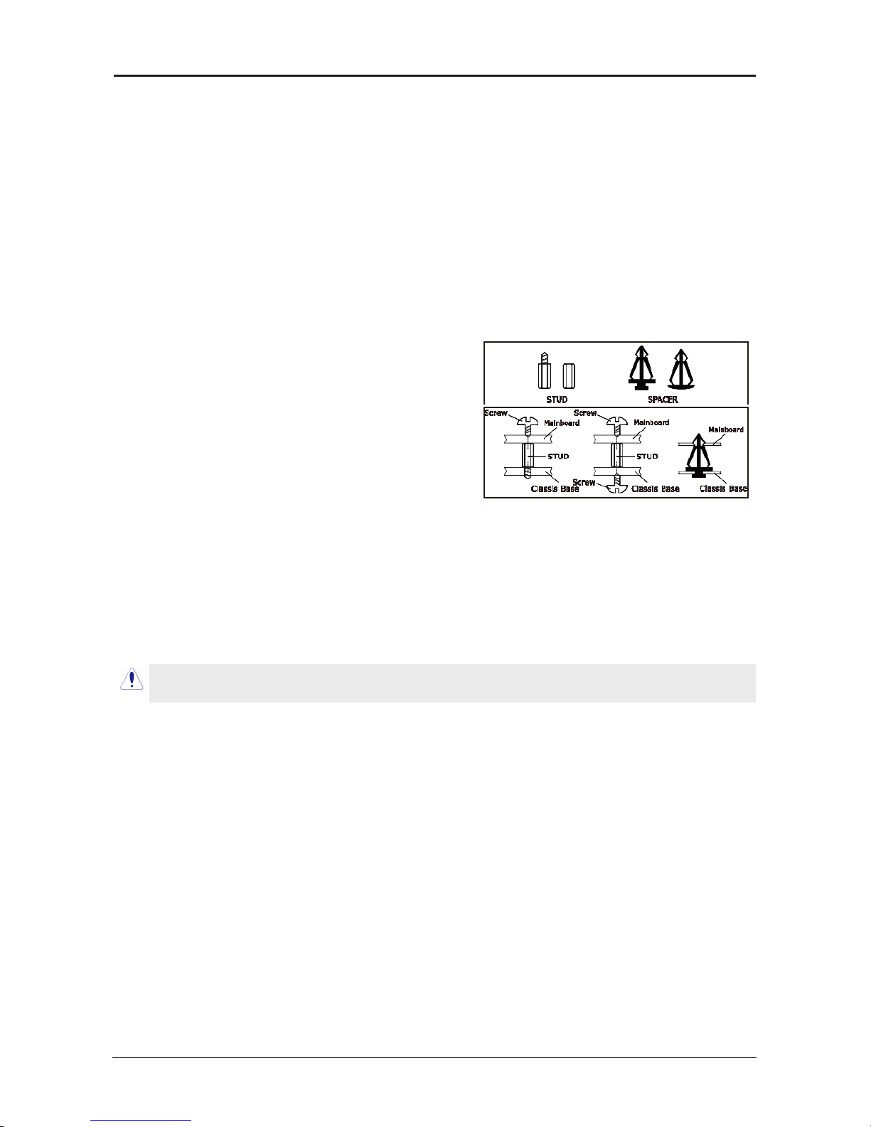
2.2
Installing Motherboard
Most computer bases have many xing holes to allow the mainboard to attached securely,
and will not short. There are two ways to attach the mainboard:
(1) Using studs
(2) Using spacers
Usually, the best way to attach the board is using
studs. When you are unable to use studs, spacers can
attach the board also. Please check the board
carefully, you will nd there are many xing holes,
line up these holes with your computer base. If holes
can line up and there are screw holes, means you can
attach the board with studs. If all holes line up and
there are only slots, means you can only attach with
spacers. Take the tip of the spacers and insert them
into the slots. After doing this, slide the board into slots to x it. Before chassis tted, make
sure everything is ok.
If there have studs locked on board, and there is not xed holes between studs and board,
uninstall the studs to avoid shorting PCB circuit.
Page 9
- 9 -
Intel Atom Series User’s Manual
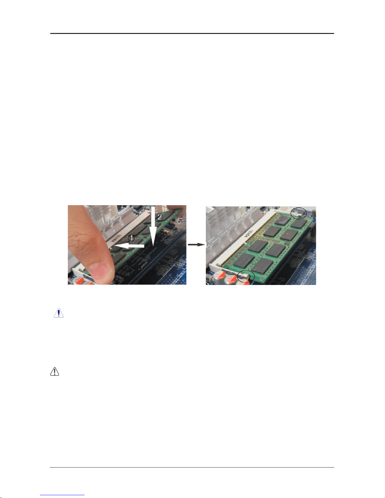
2.3 Installing Memory Module
This motherboard provides two 204-pin DDRIII (Double Data Rate) SO-DIMM slots.
Before starting the installation, please read the following warning messages:
1. Make sure your purchased memory specication is supported with the motherboard;
2. Before installing or removing memory, make sure that the computer is turned off;
3. The memory is designed with fool-proof marker, if you insert with wrong direction, it can
not be inserted.
Installing memory:
1. Before installing or removing memory, please turn off the power and unplug the AC cable.
2. Carefully grasp both ends of memory, and do not touch the metal contacts.
3. Align the memory to slots, and pay attention to the direction.
4. Inclining 30 degrees and insert, then press down untill you hear the "clicking" sound (to
avoid any demage, your strengh must be gentle).
5. To remove the memory, push out both latch of DIMM slot at the same time, and take it
out.
Memory installation illustration (only for reference):
Installation of Dual Memory Channels
This board has 2 DIMM slots, and each one representing a memory channel. The memory
works on dual channel mode only when this two memories have been all installed successfully
(Note:When use the dual channel mode, you must select the memories which with the same
capacity, frequency, and brand at the same time).
:Static will demage the electronic components of computer and memory, when doing
above step, you should contact with a grounded metial object to remove the static from your
body.
Page 10
- 10 -
Intel Atom Series User’s Manual
2.4.1 Serial ATA
connectors
The Serial ATA connectors can
connect to Serial ATA hardware or
other corresponding devices when
use Serial ATA cable
。
2.4.2 MPCIE
slot
2.4
Connecting Peripheral Devices
MPCIE: It compatible with SSD
(
While installing, incline it 30 degrees
and insert,
then press down to bolt position, and
use the screws to x it.)
Page 11
- 11 -
Intel Atom Series User’s Manual
Chapter 3 Jumpers & Headers Setup
3.1 Checking Jumper Settings
• 2-pin jumper: Plug the jumper cap onto both
pins will make it CLOSE (SHORT). Remove the
cap or plug it on another pins (keep for future
use) will activate the jumper.
• 3-pin jumper: Plug the jumper cap onto pin
1~2 or pin 2~3 will make it CLOSE (SHORT).
shorted by plugging the jumper cap in.
How to identify the PIN1?
Please check the Motherboard carefully, the PIN1
is marked by "1", white thick line or white triangle.
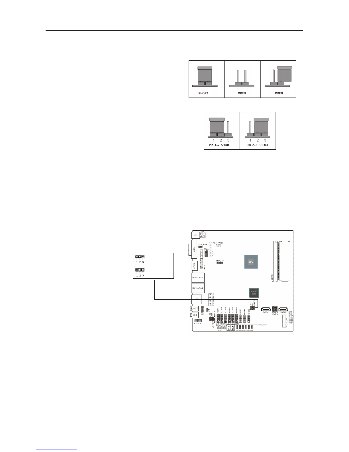
3.2 Unpluging the CMOS Header
When: (a) the CMOS data demaged, (b) you forgot the supervisor or password of BIOS,
(c) you are unable to boot-up because the frenquency of CPU was incorrectly, or (d) there
have modifications on CPU or memory modules, means you need to unplug the CMOS
header.
It uses a jumper cap to clear the CMOS setup, and reset the BIOS value to default.
• Pins 1 and 2 open circuit (Default): Normal situation
• Pins 2 and 3 shorted: Clear CMOS setup
To clear the CMOS setup and set to default values:
1. Power off the system.
2. Plug the jumper cap to pin 2-3, and wait for 3-5 seconds, then plug the cap back to pin
1-2.
3. Power on the system.
4. If the frequency of CPU set incorrect, please press the <Del> button to enter the BIOS
setup menu after powering on system.
5. Reset the running speed of CPU to default or to suitable value.
6. Save and exit the BIOS setup menu.
Default state
ClearCMOS
Page 12

- 12 -
Intel Atom Series User’s Manual
3.3
Jumpers Setting
JKB(PS/2
Keyboard power on function setting
)
PIN DEFINITION
1-2(
default setting
)
Disabled
2-3 Enabled
PIN 1-2 SHORT:
Disable keyboard power on function
PIN 2-3 SHORT:
Enable keyboard power on function
LVDS_PWR1
PIN DEFINITION
1-2 5V
2-3 3.3V
JIR1、JIR2(COM
and
IR
setting
)
PIN DEFINITION
1-2 COM
2-3 IR
JU1、JU2(FUSB2
and
MINIPCIE
setting
)
PIN DEFINITION
1-2 FUSB2
2-3 MINIPCIE
JP1-JP4
PIN DEFINITION
1-2 MINIPCIE
2-3 M-SATA
3-4 SATA2
ADJ_PWR1
PIN DEFINITION
1-2 5V
3-4 2.5V
5-6 0
JCOM1-6
pin9 denition
(
choose
JC11/12/13/14/15/16/1/2/3/4/5/6
jumpers
)
PIN
SELECTION
DEFINITION PIN SELECTION DEFINITION
JC11/12/13
JC14/15/16
CLOSE RI
JC1/2/3
JC4/5/6
1-2 +5V
OPEN USE JC1_JC6 2-3 +12V
When use the front panel USB ,JU1 and JU2 should
jump to pin1-2,and MPCIE1 is used as
wi of USB,JU1 and JU2 should jump to pin2-3.
When MPCIE_WIFI_SATA is used as wi ,JP1-JP2
should jump to pin1-2,and is used as M_SATA ,JP1-
JP4 should jump to pin2-3,
When be used as SATA2,JP1-JP4 should jump to
pin3-4.
Page 13

- 13 -
Intel Atom Series User’s Manual
3.4
Front panel pin interface
3.5
JLVDS1
pin interface(Display screen interface
)
pin definition pin definition
1 VCC 2 HD_LED
+
3 VCC 4 HD_LED
-
5 -PLED_2 6 PW_BN
7 +5V 8 GND
9 NC 10 RST_SW
11 NC 12 GND
13 SPEAK 14 +5V
15 KEY 16 -SLEEP_LED
HD_LED (Red): Hard Driver LED connector
This connector connects to the case-mounted HD LED cable,
and the LED will light when the
hard drive(s) is/are being accessed.
RST (Blue): Reset Switch
This connector connects to the case-mounted reset switch
which allows you to reboot without
having to power-off the system and thus prolonging
the life of the power supply or system.
PWR_ON (Black): Power Switch
Depending on the setting in the BIOS setup,
this switch serves two functions which will allow
you to power-on/off the system or to enter
the suspend mode.
PWR_LED (Green): Power/Standby LED
When the system's power is on, this LED will light.
When the system is in the S1 (POS - Power
on Suspend) or S3 (STR - Suspend to RAM, optional) state,
it will blink every second.
Page 14

- 14 -
Intel Atom Series User’s Manual
PIN DEFINITION PIN DEFINITION
1 VDDPAEA 2 VDDPAEA
3 GND 4 GND
5 VDDPAEA 6 VDDPAEA
7 LVDS0_N0 8 NC
9 LVDS0_P0 10 NC
11 GND 12 GND
13 LVDS0_N1 14 NC
15 LVDS0_P1 16 NC
17 GND 18 GND
19 LVDS0_N2 20 NC
21 LVDS0_P2 22 NC
23 NC 24 GND
25 LVDS0_CLKN 26 NC
27 LVDS0_CLKP 28 NC
29 GND 30 GND
31 LVDS_DDCPCLK 32 LVDS_DDCPDATA
33 GND 34 GND
35 LVDS0_N3 36 NC
37 LVDS0_P3 38 NC
39 NC 40 LVDS_VCON
24BIT (
single
) LVDS
24BIT (
double
) LVDS
PIN DEFINITION PIN DEFINITION
1 VDDPAEA 2 VDDPAEA
3 GND 4 GND
5 VDDPAEA 6 VDDPAEA
7 LVDS0_N0 8 LVDS1_N0
9 LVDS0_P0 10 LVDS1_P0
11 GND 12 GND
13 LVDS0_N1 14 LVDS1_N1
15 LVDS0_P1 16 LVDS1_P1
17 GND 18 GND
19 LVDS0_N2 20 LVDS1_N2
21 LVDS0_P2 22 LVDS1_P2
23 NC 24 GND
25 LVDS0_CLKN 26 LVDS1_CLKN
27 LVDS0_CLKP 28 LVDS1_CLKP
29 GND 30 GND
31 LVDS_DDCPCLK 32 LVDS_DDCPDATA
33 GND 34 GND
35 LVDS0_N3 36 LVDS1_N3
37 LVDS0_P3 38 LVDS1_P3
39 NC 40 LVDS_VCON
3.6
LPT
pin interface
PIN DEFINITION PIN DEFINITION PIN DEFINITION PIN DEFINITION PIN DEFINITION
1 STB 2 AFD 3 PD0 4 ERR 5 PD1
6 INIT 7 PD2 8 SLIN 9 PD3 10 GND
11 PD4 12 GND 13 PD5 14 GND 15 PD6
16 GND 17 PD7 18 GND 19 ACK 20 GND
21 BUSY 22 GND 23 PE 24 GND 25 SLCT
Page 15

- 15 -
Intel Atom Series User’s Manual
3.7 Front JVGA pin interface
3.8 GPIO
pin interface
PIN DEFINITION PIN DEFINITION
1 +5V 2 +12V
3 GPIO 4 GPIO
5 GPIO 6 GPIO
7 GPIO 8 GPIO
9 GPIO 10 GPIO
11 GND 12 GND
PIN DEFINITION PIN DEFINITION
1 GND 2 RED
3 GND 4 GREEN
5 GND 6 BLUE
7 HSYNC 8 VSYNC
9 DDC_DATA 10 DDC_CLK
Page 16

- 16 -
Intel Atom Series User’s Manual
3.9 JINVERT1 pin interface
3.10 IRDA pin interface
PIN DEFINITION PIN DEFINITION
1 VCC 2
空
3 IRRX 4 GND
5 IRTX
PIN DEFINITION PIN DEFINITION
1 12V 2 GND
3 BLEN 4 PWM
5 5V
Page 17

- 17 -
Intel Atom Series User’s Manual
3.11 FUSB1/2/3
expansion interface
3.12
Front Panel Audio output interface
PIN DEFINITION DEFINITION PIN SILK-SCREEN DEFINITION
1 PROT1L Microphone_Left 6 SENSE1_RETURN AuD_R_Return
2 AGND Ground 7 SENSE_SEND FAUDIO_JD
3 PROT1R Microphone_Right 8 NC N/A
4 PRESENCE# -ACZ_DET 9 PORT2L Line2_Left
5 PORT2R Line2_Right 10 SENSE2_RETURN AuD_L_Return
PIN DEFINITION PIN DEFINITION
1 VCC 2 VCC
3 D- 4 D5 D+ 6 D+
7 GND 8 GND
10 KEY
Page 18

- 18 -
Intel Atom Series User’s Manual
3.14 COM
Connectors
The motherboard provides 6 "2x5pin"com connectors
onboard
3
1
VCC OUT GND
PIN
DEFINITION PIN DEFINITION
1 DCD 2 RXD
3 TXD 4 DTR
5 GND 6 DSR
7 RTS 8 CTS
9 RI
3.13 S/PDIF Output Connection Header (Optional)
S/PDIF (Sony/Philips Digital Interface) is a standard audio transfer le format. It is usually
found on digital audio equipment such as a DAT (Digital Audio Tape) machine or audio
processing device. It allows the transfer of audio from one le to another without the
conversion to and from an analog format, which could degrade the signal quality.
Page 19

- 19 -
Intel Atom Series User’s Manual
3.15 KM1
pin interface
(PS/2
interface adapter
)
3.16
SATA1_PWR/SATA2_PWR(SATA power interface
)
and
J14(DC
power interface
)
PIN DEFINITION PIN DEFINITION
1 MDT 2 KB_DATA
3 MCK 4 KB_CLK
5 GND 6 GND
7 VCC 8 VCC
9 KEY 10
PIN DEFINIITON PIN DEFINITION PIN DEFINITION PIN DEFINITION
1 12V 2 GND 3 GND 4 5V
J14
SATA1_PWR/SATA2_PWR
By the power socket,the power supply can
provide power that is enough and stable
for all the components on the mainboard.
Before
inserting into the power socket,please
make be sure that the power of power
supply has been turned off ,and allthe
components and devices have been
xed exactly,Power socket has protection design,
After conrming that the direction is right ,you
can insert.
Page 20

- 20 -
Intel Atom Series User’s Manual
Chapter 4 BIOS Setup Utility
BIOS stands for Basic Input and Output System. It was once called ROM BIOS when it was
stored in a Read-Only Memory (ROM) chip. Now manufacturers would like to store BIOS in
EEPROM which means Electrically Erasable Programmable Memory. BIOS used in this series
of mainboard is stored in EEPROM, and is the first program to run when you turn on your
computer.
BIOS performs the following functions:
1. Initializing and testing hardware in your computer (a process called "POST", for Power On
Self Test).
2. Loading and running your operating system.
3. Helping your operating system and application programs manage your PC hardware by
means of a set of routines called BIOS Run-Time Service.
4.1 About BIOS Setup
BIOS Setup is an interactive BIOS program that you need to run when:
1. Changing the hardware of your system. (For example: installing a new Hard Disk etc.)
2. Modifying the behavior of your computer. (For example: changing the system time or date,
or turning special features on or off etc.)
3. Enhancing your computer's behavior. (For example: speeding up performance by turning
on shadowing or cache)
4.2 To Run BIOS Setup
First access BIOS setup menu by pressing <F1> key after “POST” is complete (before OS is
loaded). After the rst BIOS be setupped(or loaded default values) and save, the <DEL> key
will be pressed if you will enter BIOS setup menu.
4.3 About CMOS
CMOS is the memory maintained by a battery. CMOS is used to store the BIOS settings you
have selected in BIOS Setup. CMOS also maintains the internal clock. Every time you turn
on your computer, the BIOS Looks into CMOS for the settings you have selected and
congures your computer accordingly. If the battery runs out of power, the CMOS data will
be lost and POST will issue a “CMOS invalid” or “CMOS checksum invalid” message. If this
happens, you have to replace the battery and check and congure the BIOS Setup for the
new start.
4.4 The POST (Power On Self Test)
POST is an acronym for Power On Self Test. This program will test all things the BIOS does
before the operating system is started. Each of POST routines is assigned a POST code, a
unique number which is sent to I/O port 080h before the routine is executed.
Page 21

- 21 -
Intel Atom Series User’s Manual
4.5 BIOS Setup — CMOS Setup Utility
4.5.1 CMOS Setup Utility
After powering up the system, the BIOS message appears on the screen,when the rst time
or when CMOS setting wrong, there is following message appears on the screen , but if
the rst BIOS be setuped(or loaded default values) and save, the <DEL> key will be
pressed if you will enter BIOS setup menu.
If this message disappears before you respond, restart the system by pressing <Ctrl> +
<Alt>+ <Del> keys, or by pressing the reset button on computer chassis. Only when these
two methods should be fail that you restart the system by powering it off and then back on.
After pressing <F1> or <Del> key, the main menu appears.
Press <DEL> to enter SETUP
•
In order to increase system stability and performance, our engineering staff is
constantly improving the BIOS menu. The BIOS setup screens and descriptions
illustrated in this manual are for your reference only, and may not completely
match with what you see on your screen.This chapter were based mainly on
the model, unless specif cally stated.
•
Do not change the BIOS parameters unless you fully understand its function.
The menu bar on top of the screen has the following main items:
Main For changing the basic system conguration.
Advanced For changing the advanced system settings.
Chipset
For changing the system ports settings.
Boot For changing the system boot conguration.
Security For changing the system security setttings.
JUSTw00t For changing the overclocking settings.
Save & Exit For changing CMOS mode and loading default settings.
Aptio Setup Utility - Copyright (C) 2011 American Megatrends,Inc.
Main Advanced Chipset Boot Security JUSTw00t Save&Exit
BIOS Information Choose the system default
language
BIOS Vendor American Megatrends
Core Version 4.6.5.3
Compliency UEFI 2.3;PI 1.2
Project Version MB00A421
Build Date and Time 02/29/2012 12:22:00
System Language [English]
System Date [Sun 01/04/2011]
System Time [17:27:30]
Access Level Administrator
→ ←
:Select Screen
↑↓:Select Item
Enter: Select
+/-:Change Opt.
F1 :General Help
F7 :Previous Values
F9 :Optimized Defaults
F10:Save&Exit
ESC:Exit
Version 2.14.1219. (C)Copyright 2011 American Megatrends, Inc.
Page 22

- 22 -
Intel Atom Series User’s Manual
Control Key(s) Function Description
← / →
Move cursor left or right to select screens
↑
/
↓
Move cursor up or down to select items
+/
-/PU/PD
To Change option for the selected items
<Enter>
To bring up the selected screen
<ESC>
Main Menu - Quit and not save changes into CMOS Status
Page Setup Menu and Option Page Setup Menu - Exit
current page and return to Main Menu
<F1>
General help
<F7>
Previous Values
<F9>
Load Optimal Defaults
<F10>
Save conguration changes and exit setup
4.5.2 Control Keys
Press <F1> to pop up a small help window that describes the appropriate keys
to use and the available options for the highlighted item.
Please check the following table for the function description of each control key.
Page 23

- 23 -
Intel Atom Series User’s Manual
4.2.3 Main Interface
・ BIOS Information
・ System Language
To set the language of BIOS menu, such as English
・
System Date
To set the date of computer, the form is “weekday, month/ date/year”
・ System Time
The form of time is<hour><minute><second>
4.2.4 Advanced
Aptio Setup Utility - Copyright (C) 2011 American Megatrends,Inc.
Main Advanced Chipset Boot Security Save&Exit
BIOS Information
BIOS Vendor American Megatrends
Core Version 4.6.5.1
Compliency UEFI 2.3;PI 1.2
BIOS Version CT00A281
Build Date and Time 08/23/2012 09:40:09
System Language [English]
System Date [Thu 11/17/2011]
System Time [17:34:18]
Access Level Administrator
Choose the system default
language
→ ←
:Select Screen
↑↓:Select Item
Enter: Select
+/-:Change Opt.
F1 :General Help
F7 :Previous Values
F8 :Fail-Safe Values
F9 :Optimized Defaults
F10 :Save & Exit
ESC :Exit
Version 2.11.1210. Copyright (C) 2011 American Megatrends, Inc.
Aptio Setup Utility - Copyright (C) 2011 American Megatrends,Inc.
Main Advanced Chipset Boot Security Save&Exit
Legacy OpROM Support
Launch Storage OpROM [Enabled]
►
ACPI Settings
►
RTC Wake Settings
►
CPU Configuration
►
IDE Configuration
►
USB Configuration
►
Power Management
►
W83627UHG Super IO Configuration
►
WatchDogTimer Setting
►
W83627UHG H/W Monitor
S y s t e m A C P I
Parameters.
→ ←
: Select Screen
↑↓: Select Item
Enter: Select
+/-: Change Opt.
F1
:
General Help
F7: Previous Values
......
Version 2.11.1210. Copyright (C) 2011 American Megatrends, Inc.
・
Launch Storage OpROM
Seting legacy ROM devices open and close,options:Enabled,Disabled.
Press < ESC> key to return to the Advanced menu
Page 24

- 24 -
Intel Atom Series User’s Manual
・ Enable ACPI Auto Confguration
Setting the advanced power management conguration, options: Enabled,Disabled
.
・ Enable Hibernation
Enabled or disabled system ability to hibernate (OS/S4 sleep
state
). This option may be
not effective with sime OS. Options: Enabled,Disabled.
・
ACPI Sleep State
Selecting the highest ACPI sleep state the system will enter when the suspend button is
pressed. options
:Suspend Disabled, S1 only(CPU Stop Clock), S3 only(Suspend to RAM)
・
Lock Legacy Resources
Enabled or Disabled Lock of Legacy Resources.options:Enabled,Disabled.
Press < ESC> key to return to the Advanced menu
►
ACPI Settings press
<Enter>
key to turn into the submenu.
Aptio Setup Utility - Copyright (C) 2011 American Megatrends,Inc.
Advanced
Wake system with Fixed Time [Disabled]
Wake system with Dynamic Time [Disabled]
Enable or disable
System......
→ ←
: Select Screen
↑↓: Select Item
Enter: Select
+/-: Change Opt.
F1
:
General Help
......
Version 2.11.1210. Copyright (C) 2011 American Megatrends, Inc.
►
RTC Wake Settings press
<Enter>
key to turn into the submenu.
・ Wake system with Fixed Time
when choose the option"Enabled" you can set to wake the system with xed time,
options;Disabled,Enabled.
When set "wake system with Fixed time"to "Enabled",will appear the following four options:
Wake up Day/Wake up hour/Wake up minute/Wake up second.
・
Wake system with Dynamic Time
Enabled/Disabled Dynamic RTC Wake function.options: Disabled,Enabled.
Press < ESC> key to return to the Advanced menu
Aptio Setup Utility - Copyright (C) 2011 American Megatrends,Inc.
Advanced
ACPI Settings
Enable ACPI Auto Configuration [Disabled]
Enable Hibernation [Enabled]
ACPI Sleep State [S1...]
Lock Legacy Resources [Disbaled]
Enables or Disables BIOS
....
→ ←
: Select Screen
↑↓: Select Item
Enter: Select
+/-: Change Opt.
F1
:
General Help
......
Version 2.11.1210. Copyright (C) 2011 American Megatrends, Inc.
Page 25

- 25 -
Intel Atom Series User’s Manual
・ Hyper-Threading
Options:Disabled,Eanbled.
・ Execute Disable Bit(Anti-virus proyection
)
It can enhance virus protection of the computer。it can help the CPU of computer
that enforces self protection in some hostile attacks,and avoid the virus hostile attacks.
・
Limit CPUID Maximum
Setting to limit CPUID Maximum,options:Enabled,Disabled.
Press < ESC> key to return to the Advanced menu
►
IDE Confguration
press
<Enter>
key to turn into the submenu.
►
CPU Confguration press
<Enter>
key to turn into the submenu.
Aptio Setup Utility - Copyright (C) 2011 American Megatrends,Inc.
Advanced
CPU configuration
Processor Type
Intel(R) Atom(TM) CPU D2550 @ 1.86GHz
EMT64 Supported
Processor Speed 1865 MHz
System Bus Speed 533 MHz
Ratio Status 14
Actual Ratio 14
System Bus Speed 533 MHz
Processor Stepping 30661
Microcode Revision 262
L1 Cache RAM 2 x 56 k
L2 Cache RAM 2 x 512 k
Processor Core Dual
Hyper-Threading Supported
Hyper-Threading [Enabled]
Execute Disable Bit [Enabled]
Limit CPUID Maximum [Disabled]
Enabled for
Windows......
→ ←
:Select Screen
↑↓:Select Item
Enter: Select
+/-:Change Opt.
F1 :General Help
F7 :Previous Values
F8 :Fail-Safe Values
F9 :Optimized Defaults
F10 :Save & Exit
ESC :Exit
Version 2.11.1210. Copyright (C) 2011 American Megatrends, Inc.
Aptio Setup Utility - Copyright (C) 2011 American Megatrends,Inc.
Advanced
SATA Port0 Not Present
SATA Port1 Not Present
SATA Controller(s) [Enabled]
Configure SATA as [IDE]
Misc Configuration for hard disk
SAT A Por t(0- 3) Devi ce
Names if ....
→ ←
: Select Screen
↑↓
: Select Item
Enter: Select
+/-: Change Opt.
F1: General Help
........
Version 2.11.1210. Copyright (C) 2011 American Megatrends, Inc.
Page 26

- 26 -
Intel Atom Series User’s Manual
►
USB Confguration
press
<Enter>
key to turn into the submenu.
・ Legacy USB Support
・ EHCI Hand-Off
This item can be used to open/close BIOS EHCI Hand-off function.
Options:Enabled,Disabled
・ Device reset time-out
Options: 10 sec、20 sec、30 sec、40 sec.
・
Device power-up delay
Options: Auto、Manual.
Press < ESC> key to return to the Advanced menu
・ SATA Controller(s)
Options:Enabled,Disabled.
・ Confgure SATA As
Installing mode of SATA system,Options:IDE,AHCI.
Press < ESC> key to return to the Advanced menu
Aptio Setup Utility - Copyright (C) 2011 American Megatrends,Inc.
Advanced
USB Configuration
USB Devices:
1 Keyboard
Legacy USB Support [Enabled]
EHCI Hand-off [Disabled]
Device reset time-out [20 sec]
Device power-up delay [Auto]
Enables Legacy USB...
→ ←
: Select Screen
↑↓: Select Item
Enter: Select
+/-: Change Opt.
F1
:
General Help
F7: Previous Values
.......
Version 2.11.1210. Copyright (C) 2011 American Megatrends, Inc.
►
Power Management
press
<Enter>
key to turn into the submenu.
Aptio Setup Utility - Copyright (C) 2011 American Megatrends,Inc.
Advanced
Power Management
Wake By PME [Enabled]
AC Power Loss [Power Off]
Wake By PME
→ ←
: Select Screen
↑↓: Select Item
Enter: Select
+/-: Change Opt.
F1
:
General Help
......
Version 2.11.1210. Copyright (C) 2011 American Megatrends, Inc.
Setting support legacy input/output devices, such as the
mouse, keyboard etc, options: Enabled,Disabled,Auto.
Page 27

- 27 -
Intel Atom Series User’s Manual
・
Wake By PME
Options:Enabled,Disabled
。
・
AC Power Loss
►
W83627UHG Super IO Confguration
press
<Enter>
key to turn into the submenu.
Aptio Setup Utility - Copyright (C) 2011 American Megatrends,Inc.
Advanced
W83627UHG Super IO Configuration
W83627UHG Super IO Chip W83627UHG
►
Serial Port 1 Configuration
►
Serial Port 2 Configuration
►
Serial Port 3 Configuration
►
Serial Port 4 Configuration
►
Serial Port 5 Configuration
►
Serial Port 6 Configuration
►
Paraller Port Configuration
Se t P a r a m e t ers o f
Serial Port1(COMA)
→ ←
: Select Screen
↑↓: Select Item
Enter: Select
+/-: Change Opt.
F1
:
General Help
F7: Previous Values
.......
Version 2.11.1210. Copyright (C) 2011 American Megatrends, Inc.
►
Serial Port 1/2/3/4/5/6 Confguration
press
<Enter>
key to turn into the submenu.
Aptio Setup Utility - Copyright (C) 2011 American Megatrends,Inc.
Advanced
Serial Port 2 Configuration
Enable or Disable
Serial Port(COM)
→ ←
:Select Screen
↑↓:Select Item
Enter: Select
+/-:Change Opt.
......
Serial Port [Enabled]
Device Settings IO=2F8h; IRQ=3;
Change Settings [Auto]
Device Mode [Standard..]
Version 2.11.1210. Copyright (C) 2011 American Megatrends, Inc.
・ Serial Port
Setting switch of serial port, options: Enabled,Disabled.
・ Change Settings
Setting IRQ for serial port,options; Auto , specied value .
・
Device Mode
Press < ESC> key to return to the Advanced menu
This item selects the system action after an AC power failure.
[Power Off]: When power returns after an AC power failure, the system’s power remains
off. You must press the Power button to power-on the system.
[Power On]: When power returns after an AC power failure, the system’s power will be
powered on automatically.
[Last State]: When power returns after an AC power failure, the system will return to the
state where you left off before power failure occurred. If the system’s power
is off when AC power failure occurs, it will remain off when power returns. If
the system’s power is on when AC power failure occurs, the system will
power-on when power returns.
Press < ESC> key to return to the Advanced menu
Page 28

- 28 -
Intel Atom Series User’s Manual
►
WatchDogTimer Setting
press
<Enter>
key to turn into the submenu.
►
Parallel Port Confguration
press
<Enter>
key to turn into the submenu.
Aptio Setup Utility - Copyright (C) 2011 American Megatrends,Inc.
Advanced
Parallel Port Configuration
Enable or Disable
Parallel Port(LPT/LPTE)
→ ←
:Select Screen
↑↓:Select Item
Enter: Select
+/-:Change Opt.
F1:General Help
......
Parallel Port [Enabled]
Device Settings IO=378h; IRQ=5
Change Settings [Auto]
Device Mode [STD..]
Version 2.11.1210. Copyright (C) 2011 American Megatrends, Inc.
・ Parallel Port
Parallel port controller,Options:Enabled,Disabled
。
・ Change Settings
Setting IO for serial port,options; Auto , specied value .
・ Device Mode
Press < ESC> key to return to the Advanced menu
・
WatchDogTimer
When the number is more than the setting number,the computer wiil automaticly start.
Press < ESC> key to return to the Advanced menu
Aptio Setup Utility - Copyright (C) 2011 American Megatrends,Inc.
Advanced
W a t c h D o g T i m e r [ D i s a b l e d ]
WatchDogTimer Setting
→ ←
:Select Screen
↑↓:Select Item
Enter: Select
+/-:Change Opt.
......
Version 2.11.1210. Copyright (C) 2011 American Megatrends, Inc.
Page 29

- 29 -
Intel Atom Series User’s Manual
►
W83627UHG HW Monitor
press
<Enter>
key to turn into the submenu.
Aptio Setup Utility - Copyright (C) 2011 American Megatrends,Inc.
Advanced
Pc Health Status
Sys Temperature : +28
CPU Temperature : +38
SysFan Speed : N/A
CpuFan Speed : 1864
VCORE : +1.192 V
+1.05V : +1.032 V
+12V : +12.091 V
Memory Voltage : +1.560 V
AVCC : +5.058 V
VBAT : +3.232 V
→ ←
:Select Screen
↑↓:Select Item
Enter: Select
+/-:Change Opt.
F1:General Help
F7:Previous Values
......
Version 2.11.1210. Copyright (C) 2011 American Megatrends, Inc.
The item monitors hardware state,including the temperture of CPU 、fan、all kinds of voltage
etc.
Press < ESC> key to return to the Advanced menu
4.2.5 Chipset
►
Host Bridge
press
<Enter>
key to turn into the submenu.
Aptio Setup Utility - Copyright (C) 2011 American Megatrends,Inc.
Main Advanced Chipset Boot Security Save&Exit
►
Host Bridge
►
South Bridge
Host Bridge parameters
→ ←
: Select Screen
↑↓
: Select Item
Enter: Select
+/-: Change Opt.
F1: General Help
F: Previous Values
......
Version 2.11.1210. Copyright (C) 2011 American Megatrends, Inc.
Aptio Setup Utility - Copyright (C) 2011 American Megatrends,Inc.
Chipset
►
Intel IGD Configuration
******** Memory Information *********
Memory Frequency 1067 MHz(DDR3)
Total Memory 2048 MB
DIMM#1 2048 MB
Config Intel IGD Settings
...
→ ←
: Select Screen
↑↓
: Select Item
Enter: Select
+/-: Change Opt.
F1: General Help
........
Version 2.11.1210. Copyright (C) 2011 American Megatrends, Inc.
Page 30

- 30 -
Intel Atom Series User’s Manual
►
Intel IGD Confguration
press
<Enter>
key to turn into the submenu.
Aptio Setup Utility - Copyright (C) 2011 American Megatrends,Inc.
Chipset
Intel IGD Configuration
Auto Disable IGD [Enabled]
IGFX-Boot Type [VBIOS Default]
LCD Panel Type [VBIOS Default]
IGD Clock Source [External Clock]
Fixed Graphics Memory Size [128MB]
Auto disable IGD...
→ ←
: Select Screen
↑↓
: Select Item
Enter: Select
+/-: Change Opt.
F1: General Help
........
Version 2.11.1210. Copyright (C) 2011 American Megatrends, Inc.
►
South Bridge
Aptio Setup Utility - Copyright (C) 2011 American Megatrends,Inc.
Chipset
USB Function [Enabled]
Onboard LAN 1 Controller [Auto]
Onboard LAN 2 Controller [Auto]
Control the USB UHCI...
→ ←
: Select Screen
↑↓: Select Item
Enter: Select
+/-: Change Opt.
F1
:
General Help
......
Version 2.11.1210. Copyright (C) 2011 American Megatrends, Inc.
・
USB Function
USB
Controller,options:Enabled,Disabled
。
・
LAN1/2 Controller
)
Options :Auto,Enabled,Disabled
。
Press < ESC> key to return to the Chipset menu
The item allows to set relevant information of IGD,suggesting not to change
their default settings without completely understanding.
Press < ESC> key to return to the Chipest menu
press
<Enter>
key to turn into the submenu.
Page 31

- 31 -
Intel Atom Series User’s Manual
4.2.6 Boot press
<Enter>
key to turn into the submenu.
Aptio Setup Utility - Copyright (C) 2011 American Megatrends,Inc.
Main Advanced Chipset Boot Security Save&Exit
Boot Configuration
Setup Prompt Timeout
Bootup NumLock State
Full Screen Logo
GateA20 Active
Option ROM Messages
Interrupt 19 Capture
Boot Option Priorities
1
[On]
[Disabled]
[Upon Request]
[Force BIOS]
[Enabled]
Number of seconds to wait for
setup activation key.
65535(0xFFFF) means indefinite
waiting.
→ ←
: Select Screen
↑↓
: Select Item
Enter: Select
+/-: Change Opt.
F1
:
General Help
......
Version 2.11.1210. Copyright (C) 2011 American Megatrends, Inc.
・ Setup Prompt Timeout
This option sets how long the prompt message will last.
・
Bootup NumLock State
・
Full Screen Logo
options:Disabled,Enabled
。
・
GateA20 Active
Options:Upon Request,Always.
・
Option ROM Messages
Options:Force BIOS,Keep Current.
・
Interrupt 19 Capture
options:Disabled,Enabled.
Press < ESC> key to return to the Boot menu
It is used to set the state of the Numlock key after system starts up. When "On" is chosen,
the Numlock key will be ON and number keys on the keypad are available after system
starts up;
When "Off" is chosen, Numlock will remain OFF after system starts up.
Page 32

- 32 -
Intel Atom Series User’s Manual
4.2.7 Security press
<Enter>
key to turn into the submenu.
Aptio Setup Utility - Copyright (C) 2011 American Megatrends,Inc.
Main Advanced Chipset Boot Security Save&Exit
Password Description
If ONLY the Administrator'password is set,
then this only limits access to Setup and is
only asked for when entering Setup.
If ONLY the User's password is set, then this
isa power on password and must be entered to
boot or enter Setup. In Setup the User will
have Admimistrator rights.
The password length must be
in the following range:
Minimum length 3
Maximum length 20
Administrator Password
User Password
Set Administrator
Password.
→ ←
: Select Screen
↑↓: Select Item
Enter: Select
+/-: Change Opt.
F1
:
General Help
F2: Previous Values
F9:Optimized Defaults
F10:Save & Exit
ESC:Exit
Version 2.11.1210. Copyright (C) 2011 American Megatrends, Inc.
• Administrator Password
This option is used to set an administrator password, as the following steps:
1. Move the cursor to the Administrator Password item, press <Enter>.
2. In the "Create New Password" dialog box, enter 3 to 20 characters or numbers to be
set, press <Enter>, and enter again in the "Conrm Password" dialog box to conrm
the password.
If the prompt is " Invalid Password! ", the passwords do not match, pleasere-enter again.
To clear the system administrator password, select "Administrator Password", in "Enter
Current Password" dialog box enter the old password, and in the "Create New Password"
press <Enter>, password will be cleared.
• User Password
The option is to set the user password, setting steps are the same as setting the
"Administrator Password"
.
Press < ESC> key to return to the
Security
menu
Page 33

- 33 -
Intel Atom Series User’s Manual
4.2.8 Exit press
<Enter>
key to turn into the submenu.
Aptio Setup Utility - Copyright (C) 2011 American Megatrends,Inc.
Main Advanced Chipset Boot Security Save&Exit
Save Changes and Exit
Discard Changes and Exit
Save Changes and Reset
Discard Changes and Reset
Save Options
Save Changes
Discard Changes
Restore Defaults
Save as User Defaults
Restore User Defaults
Boot Override
Exit system setup after
saving the changes.
→ ←
: Select Screen
↑↓: Select Item
Enter: Select
+/-: Change Opt.
F1
:
General Help
F2: Previous Values
F9: Optimized Defaults
F10: Save & Exit
ESC: Exit
Version 2.11.1210. Copyright (C) 2011 American Megatrends, Inc.
・ Save Changes and Exit
Select "Save Changes and Exit", and press the Enter key, and select "Yes" button, so save
all settings the results to the CMOS RAM and exit BIOS setup program. If not stored, then
select "No" or Press "ESC" key and return to the "Save & Exit" menu.
・ Discard Changes and Exit
Select "Discard changes and exit", select "Yes" and press <Enter> to give up on BIOS
program changes and exit BIOS setup program. Select "No" or press "ESC" and return to
the main menu.
・Save Changes and Reset
Select "Save Changes and Reset", and select "Yes" and press <Enter> to save the changes
made to the BIOS and restart. Select "No" or press "ESC" and return to the main menu.
・
Discard Changes and Reset
Select "Discard Changes and Reset", select "Yes" and press <Enter> to give up to save the
BIOS changes and restart. Select "No" or press "ESC" and return to the main menu.
・Save Changes
Select "Save Changes", select "Yes" and press <Enter> to save the BIOS changes. Select
"No" or press "ESC" key and return to the main menu.
・Discard Changes
Select "Discard Changes", select "Yes" and press <Enter> to discard the BIOS changes.
Select "No" or press "ESC" key and return to the main menu.
・ Restore Defaults
Select "Restore Defaults", select "Yes" and press <Enter> allows users to restore all the BIOS
options to optimize the value, select "No" or press "ESC" and return to the main menu.
・ Save as User Defaults
Select "Save as User Defaults", choose "Yes" would allow you to save your personalized
settings as BIOS default values, choose "No" or by pressing "ESC" will return to the main
menu.
・ Restore User Defaults
Select "Restore User Defaults", select "Yes" and press <Enter> allows the user to restore the
user's personal BIOS settings, select "No" or press "ESC" and return to the main menu.
・Boot Override
Page 34

- 34 -
Intel Atom Series User’s Manual
Chapter 5 Driver Installation
Check your package and there is Driver DVD included. This DVD consists of all drivers you need.
In addition, this DVD also include an auto detect software which can tell you which hardware is
installed, and which drivers needed so that your system can function properly.
Insert DVD into your DVD-ROM drive and the menu should appear as below. If the menu does
not appear, double-click My Computer / double-click DVD-ROM drive or click Start / click Run /
type X:\AUTORUN.EXE (assuming X is your DVD-ROM drive).
(This picture is only for reference)
From the Mainboard Drivers you may make 9 selections:
1. Chipset Driver
2. VGA Driver
3. LAN Driver
4. Audio Driver
5. IR Driver
6. Media Card Reader Driver
Please click on the options ,and install relevantly corresponding driver.
(This picture is only for reference)
Page 35

- 35 -
Intel Atom Series User’s Manual
Carried out under the Ministry of Information Industry
of the People's Republic of China released the <<Electronic
Information Products Pollution Con trol Management
Measures >> SJ/T11364-2006 standard requirements,
pollution control identication of the products and toxic and
hazardous substances or elements of identity are described
below:
The names and contents of toxic and hazardous substances or elements in the product
Toxic and hazardous substances or elements logo:
Part Name
PCB Board
Structure
Chipset
Connector
Passive electronic
components
Help welding, thermal
grease, labels and other
supplies
Wire
Weld metal
Toxic and hazardous substances or elements
O : Indicates that this toxic and hazardous substance content in all of the components
of homogeneous material provisions of the SJ/T11363-2006 standard limited
requirement.
X :Indicates that this toxic or hazardous substances at least in the part of a
homogeneous material content than SJ/T11363-2006 standards limited requirement.
Note: X The location of the lead content exceeds the limit requirement of ST/T113632006's standard, but in line with the European Union RoHS Directive exemption clause.
(Pb)
(Hg)
(Cd)
(Cr(VI)) (PBB)
(PBDE)
Toxic and hazardous substances or elements logo:
 Loading...