

Page 1
Page 2

Intel® Itanium® Architecture
Software Developer’s Manual
Volume 4: IA-32 Instruction Set Reference
Revision 2.3
May 2010
Document Number: 323208
Page 3

THIS DOCUMENT IS PROVIDED “AS IS” WITH NO WARRANTIES WHATSOEVER, INCLUDING ANY WARRANTY OF
MERCHANTABILITY, FITNESS FOR ANY PARTICULAR PURPOSE, OR ANY WARRANTY OTHERWISE ARISING OUT OF ANY PROPOSAL,
SPECIFICATION OR SAMPLE.
®
Information in this document is provided in connection with Intel
otherwise, to any intellectual property rights is granted by this document. Except as provided in Intel's Terms and Conditions of
Sale for such products, Intel assumes no liability whatsoever, and Intel disclaims any express or implied warranty, relating to sale
and/or use of Intel products including liability or warranties relating to fitness for a particular purpose, merchantability, or
infringement of any patent, copyright or other intellectual property right. Intel products are not intended for use in medical, life
products. No license, express or implied, by estoppel or
saving, or life sustaining applications.
Intel may make changes to specifications and product descriptions at any time, without notice.
Designers must not rely on the absence or characteristics of any features or instructions marked “reserved” or “undefined.” Intel
reserves these for future definition and shall have no responsibility whatsoever for conflicts or incompatibilities arising from future
changes to them.
®
processors based on the Itanium architecture may contain design defects or errors known as errata which may cause the
Intel
product to deviate from published specifications. Current characterized errata are available on request.
Contact your local Intel sales office or your distributor to obtain the latest specifications and before placing your product order.
Copies of documents which have an order number and are referenced in this document, or other Intel literature, may be obtained
by calling1-800-548-4725, or by visiting Intel's website at http://www.intel.com.
Intel, Itanium, Pentium, VTune and MMX are trademarks or registered trademarks of Intel Corporation or its subsidiaries in the
United States and other countries.
Copyright © 1999-2010, Intel Corporation
*Other names and brands may be claimed as the property of others.
Intel® Itanium® Architecture Software Developer’s Manual, Rev. 2.3 398
Page 4

Contents
1 About this Manual . . . . . . . . . . . . . . . . . . . . . . . . . . . . . . . . . . . . . . . . . . . . . . . . . . . . . . . . . 4:1
1.1 Overview of Volume 1: Application Architecture . . . . . . . . . . . . . . . . . . . . . . . . . . . . . 4:1
1.1.1 Part 1: Application Architecture Guide . . . . . . . . . . . . . . . . . . . . . . . . . . . . 4:1
1.1.2 Part 2: Optimization Guide for the Intel® Itanium® Architecture . . . . . . . . 4:1
1.2 Overview of Volume 2: System Architecture. . . . . . . . . . . . . . . . . . . . . . . . . . . . . . . . 4:2
1.2.1 Part 1: System Architecture Guide . . . . . . . . . . . . . . . . . . . . . . . . . . . . . . . 4:2
1.2.2 Part 2: System Programmer’s Guide . . . . . . . . . . . . . . . . . . . . . . . . . . . . . 4:3
1.2.3 Appendices. . . . . . . . . . . . . . . . . . . . . . . . . . . . . . . . . . . . . . . . . . . . . . . . . 4:4
1.3 Overview of Volume 3: Intel® Itanium® Instruction Set Reference . . . . . . . . . . . . . . 4:4
1.4 Overview of Volume 4: IA-32 Instruction Set Reference. . . . . . . . . . . . . . . . . . . . . . . 4:4
1.5 Terminology . . . . . . . . . . . . . . . . . . . . . . . . . . . . . . . . . . . . . . . . . . . . . . . . . . . . . . . . 4:5
1.6 Related Documents . . . . . . . . . . . . . . . . . . . . . . . . . . . . . . . . . . . . . . . . . . . . . . . . . . 4:5
1.7 Revision History . . . . . . . . . . . . . . . . . . . . . . . . . . . . . . . . . . . . . . . . . . . . . . . . . . . . . 4:6
2 Base IA-32 Instruction Reference . . . . . . . . . . . . . . . . . . . . . . . . . . . . . . . . . . . . . . . . . . . 4:11
2.1 Additional Intel
2.2 Interpreting the IA-32 Instruction Reference Pages . . . . . . . . . . . . . . . . . . . . . . . . . 4:12
2.2.1 IA-32 Instruction Format . . . . . . . . . . . . . . . . . . . . . . . . . . . . . . . . . . . . . . 4:12
2.2.2 Operation . . . . . . . . . . . . . . . . . . . . . . . . . . . . . . . . . . . . . . . . . . . . . . . . . 4:15
2.2.3 Flags Affected. . . . . . . . . . . . . . . . . . . . . . . . . . . . . . . . . . . . . . . . . . . . . . 4:18
2.2.4 FPU Flags Affected . . . . . . . . . . . . . . . . . . . . . . . . . . . . . . . . . . . . . . . . . 4:18
2.2.5 Protected Mode Exceptions . . . . . . . . . . . . . . . . . . . . . . . . . . . . . . . . . . . 4:19
2.2.6 Real-address Mode Exceptions . . . . . . . . . . . . . . . . . . . . . . . . . . . . . . . . 4:19
2.2.7 Virtual-8086 Mode Exceptions . . . . . . . . . . . . . . . . . . . . . . . . . . . . . . . . . 4:19
2.3 IA-32 Base Instruction Reference. . . . . . . . . . . . . . . . . . . . . . . . . . . . . . . . . . . . . . . 4:20
3IA-32 Intel
2.2.8 Floating-point Exceptions . . . . . . . . . . . . . . . . . . . . . . . . . . . . . . . . . . . . . 4:20
®
MMX™ Technology Instruction Reference . . . . . . . . . . . . . . . . . . . . . . . . . 4:399
®
Itanium® Faults . . . . . . . . . . . . . . . . . . . . . . . . . . . . . . . . . . . . . . . 4:11
4 IA-32 SSE Instruction Reference . . . . . . . . . . . . . . . . . . . . . . . . . . . . . . . . . . . . . . . . . . . 4:463
4.1 IA-32 SSE Instructions . . . . . . . . . . . . . . . . . . . . . . . . . . . . . . . . . . . . . . . . . . . . . . 4:463
4.2 About the Intel
4.3 Single Instruction Multiple Data . . . . . . . . . . . . . . . . . . . . . . . . . . . . . . . . . . . . . . . 4:464
4.4 New Data Types . . . . . . . . . . . . . . . . . . . . . . . . . . . . . . . . . . . . . . . . . . . . . . . . . . . 4:464
4.5 SSE Registers . . . . . . . . . . . . . . . . . . . . . . . . . . . . . . . . . . . . . . . . . . . . . . . . . . . . 4:465
4.6 Extended Instruction Set. . . . . . . . . . . . . . . . . . . . . . . . . . . . . . . . . . . . . . . . . . . . . 4:465
4.6.1 Instruction Group Review . . . . . . . . . . . . . . . . . . . . . . . . . . . . . . . . . . . . 4:466
4.7 IEEE Compliance . . . . . . . . . . . . . . . . . . . . . . . . . . . . . . . . . . . . . . . . . . . . . . . . . . 4:474
4.7.1 Real Number System . . . . . . . . . . . . . . . . . . . . . . . . . . . . . . . . . . . . . . . 4:474
4.7.2 Operating on NaNs. . . . . . . . . . . . . . . . . . . . . . . . . . . . . . . . . . . . . . . . . 4:480
4.8 Data Formats . . . . . . . . . . . . . . . . . . . . . . . . . . . . . . . . . . . . . . . . . . . . . . . . . . . . . 4:481
4.8.1 Memory Data Formats . . . . . . . . . . . . . . . . . . . . . . . . . . . . . . . . . . . . . . 4:481
4.8.2 SSE Register Data Formats . . . . . . . . . . . . . . . . . . . . . . . . . . . . . . . . . . 4:481
4.9 Instruction Formats . . . . . . . . . . . . . . . . . . . . . . . . . . . . . . . . . . . . . . . . . . . . . . . . . 4:483
4.10 Instruction Prefixes . . . . . . . . . . . . . . . . . . . . . . . . . . . . . . . . . . . . . . . . . . . . . . . . . 4:483
4.11 Reserved Behavior and Software Compatibility . . . . . . . . . . . . . . . . . . . . . . . . . . . 4:484
4.12 Notations. . . . . . . . . . . . . . . . . . . . . . . . . . . . . . . . . . . . . . . . . . . . . . . . . . . . . . . . . 4:484
4.13 SIMD Integer Instruction Set Extensions . . . . . . . . . . . . . . . . . . . . . . . . . . . . . . . . 4:562
4.14 Cacheability Control Instructions . . . . . . . . . . . . . . . . . . . . . . . . . . . . . . . . . . . . . . 4:575
®
SSE Architecture . . . . . . . . . . . . . . . . . . . . . . . . . . . . . . . . . . . . . 4:463
Index . . . . . . . . . . . . . . . . . . . . . . . . . . . . . . . . . . . . . . . . . . . . . . . . . . . . . . . . . . . . . . . . . . . . . . . . 4:583
Intel® Itanium® Architecture Software Developer’s Manual, Rev. 2.3 399
Page 5

Figures
2-2 Bit Offset for BIT[EAX,21]. . . . . . . . . . . . . . . . . . . . . . . . . . . . . . . . . . . . . . . . . . . . . . . . . . . . 4:18
2-3 Memory Bit Indexing. . . . . . . . . . . . . . . . . . . . . . . . . . . . . . . . . . . . . . . . . . . . . . . . . . . . . . . . 4:18
2-4 Version Information in Registers EAX . . . . . . . . . . . . . . . . . . . . . . . . . . . . . . . . . . . . . . . . . . 4:79
3-1 Operation of the MOVD Instruction . . . . . . . . . . . . . . . . . . . . . . . . . . . . . . . . . . . . . . . . . . . 4:401
3-2 Operation of the MOVQ Instruction . . . . . . . . . . . . . . . . . . . . . . . . . . . . . . . . . . . . . . . . . . . 4:403
3-3 Operation of the PACKSSDW Instruction. . . . . . . . . . . . . . . . . . . . . . . . . . . . . . . . . . . . . . . 4:405
3-4 Operation of the PACKUSWB Instruction. . . . . . . . . . . . . . . . . . . . . . . . . . . . . . . . . . . . . . . 4:408
3-5 Operation of the PADDW Instruction . . . . . . . . . . . . . . . . . . . . . . . . . . . . . . . . . . . . . . . . . . 4:410
3-6 Operation of the PADDSW Instruction . . . . . . . . . . . . . . . . . . . . . . . . . . . . . . . . . . . . . . . . . 4:413
3-7 Operation of the PADDUSB Instruction . . . . . . . . . . . . . . . . . . . . . . . . . . . . . . . . . . . . . . . . 4:416
3-8 Operation of the PAND Instruction . . . . . . . . . . . . . . . . . . . . . . . . . . . . . . . . . . . . . . . . . . . . 4:419
3-9 Operation of the PANDN Instruction. . . . . . . . . . . . . . . . . . . . . . . . . . . . . . . . . . . . . . . . . . . 4:421
3-10 Operation of the PCMPEQW Instruction . . . . . . . . . . . . . . . . . . . . . . . . . . . . . . . . . . . . . . . 4:423
3-11 Operation of the PCMPGTW Instruction . . . . . . . . . . . . . . . . . . . . . . . . . . . . . . . . . . . . . . . 4:426
3-12 Operation of the PMADDWD Instruction . . . . . . . . . . . . . . . . . . . . . . . . . . . . . . . . . . . . . . . 4:429
3-13 Operation of the PMULHW Instruction . . . . . . . . . . . . . . . . . . . . . . . . . . . . . . . . . . . . . . . . . 4:431
3-14 Operation of the PMULLW Instruction . . . . . . . . . . . . . . . . . . . . . . . . . . . . . . . . . . . . . . . . . 4:433
3-15 Operation of the POR Instruction. . . . . . . . . . . . . . . . . . . . . . . . . . . . . . . . . . . . . . . . . . . . . 4:435
3-16 Operation of the PSLLW Instruction . . . . . . . . . . . . . . . . . . . . . . . . . . . . . . . . . . . . . . . . . . . 4:437
3-17 Operation of the PSRAW Instruction . . . . . . . . . . . . . . . . . . . . . . . . . . . . . . . . . . . . . . . . . . 4:440
3-18 Operation of the PSRLW Instruction . . . . . . . . . . . . . . . . . . . . . . . . . . . . . . . . . . . . . . . . . . 4:443
3-19 Operation of the PSUBW Instruction . . . . . . . . . . . . . . . . . . . . . . . . . . . . . . . . . . . . . . . . . . 4:446
3-20 Operation of the PSUBSW Instruction . . . . . . . . . . . . . . . . . . . . . . . . . . . . . . . . . . . . . . . . . 4:449
3-21 Operation of the PSUBUSB Instruction . . . . . . . . . . . . . . . . . . . . . . . . . . . . . . . . . . . . . . . . 4:452
3-22 High-order Unpacking and Interleaving of Bytes with the PUNPCKHBW Instruction. . . . . . 4:455
3-23 Low-order Unpacking and Interleaving of Bytes with the PUNPCKLBW Instruction . . . . . . 4:458
3-24 Operation of the PXOR Instruction. . . . . . . . . . . . . . . . . . . . . . . . . . . . . . . . . . . . . . . . . . . . 4:461
4-1 Packed Single-FP Data Type . . . . . . . . . . . . . . . . . . . . . . . . . . . . . . . . . . . . . . . . . . . . . . . . 4:464
4-2 SSE Register Set . . . . . . . . . . . . . . . . . . . . . . . . . . . . . . . . . . . . . . . . . . . . . . . . . . . . . . . . . 4:465
4-3 Packed Operation. . . . . . . . . . . . . . . . . . . . . . . . . . . . . . . . . . . . . . . . . . . . . . . . . . . . . . . . . 4:466
4-4 Scalar Operation. . . . . . . . . . . . . . . . . . . . . . . . . . . . . . . . . . . . . . . . . . . . . . . . . . . . . . . . . . 4:466
4-5 Packed Shuffle Operation. . . . . . . . . . . . . . . . . . . . . . . . . . . . . . . . . . . . . . . . . . . . . . . . . . . 4:468
4-6 Unpack High Operation . . . . . . . . . . . . . . . . . . . . . . . . . . . . . . . . . . . . . . . . . . . . . . . . . . . . 4:469
4-7 Unpack Low Operation. . . . . . . . . . . . . . . . . . . . . . . . . . . . . . . . . . . . . . . . . . . . . . . . . . . . . 4:469
4-8 Binary Real Number System . . . . . . . . . . . . . . . . . . . . . . . . . . . . . . . . . . . . . . . . . . . . . . . . 4:475
4-9 Binary Floating-point Format . . . . . . . . . . . . . . . . . . . . . . . . . . . . . . . . . . . . . . . . . . . . . . . . 4:476
4-10 Real Numbers and NaNs . . . . . . . . . . . . . . . . . . . . . . . . . . . . . . . . . . . . . . . . . . . . . . . . . . . 4:478
4-11 Four Packed FP Data in Memory (at address 1000H) . . . . . . . . . . . . . . . . . . . . . . . . . . . . . 4:481
Tables
2-1 Register Encodings Associated with the +rb, +rw, and +rd Nomenclature . . . . . . . . . .4:13
2-2 Exception Mnemonics, Names, and Vector Numbers . . . . . . . . . . . . . . . . . . . . .4:19
2-3 Floating-point Exception Mnemonics and Names . . . . . . . . . . . . . . . . . . . . . . .4:20
2-4 Information Returned by CPUID Instruction . . . . . . . . . . . . . . . . . . . . . . . . . .4:78
2-5 Feature Flags Returned in EDX Register . . . . . . . . . . . . . . . . . . . . . . . . . . .4:80
400 Intel® Itanium® Architecture Software Developer’s Manual, Rev. 2.3
Page 6

2-6 FPATAN Zeros and NaNs . . . . . . . . . . . . . . . . . . . . . . . . . . . . . . . . . . 4:149
2-7 FPREM Zeros and NaNs . . . . . . . . . . . . . . . . . . . . . . . . . . . . . . . . . . 4:151
2-8 FPREM1 Zeros and NaNs. . . . . . . . . . . . . . . . . . . . . . . . . . . . . . . . . . 4:154
2-9 FSUB Zeros and NaNs . . . . . . . . . . . . . . . . . . . . . . . . . . . . . . . . . . . 4:183
2-10 FSUBR Zeros and NaNs . . . . . . . . . . . . . . . . . . . . . . . . . . . . . . . . . . 4:186
2-11 FYL2X Zeros and NaNs . . . . . . . . . . . . . . . . . . . . . . . . . . . . . . . . . . .4:199
2-12 FYL2XP1 Zeros and NaNs . . . . . . . . . . . . . . . . . . . . . . . . . . . . . . . . . 4:201
2-13 IDIV Operands. . . . . . . . . . . . . . . . . . . . . . . . . . . . . . . . . . . . . . . . 4:204
2-14 INT Cases . . . . . . . . . . . . . . . . . . . . . . . . . . . . . . . . . . . . . . . . . . 4:218
2-15 LAR Descriptor Validity . . . . . . . . . . . . . . . . . . . . . . . . . . . . . . . . . . . 4:253
2-16 LEA Address and Operand Sizes . . . . . . . . . . . . . . . . . . . . . . . . . . . . . . 4:258
2-17 Repeat Conditions . . . . . . . . . . . . . . . . . . . . . . . . . . . . . . . . . . . . . . 4:338
4-1 Real Number Notation . . . . . . . . . . . . . . . . . . . . . . . . . . . . . . . . . . . .4:476
4-2 Denormalization Process . . . . . . . . . . . . . . . . . . . . . . . . . . . . . . . . . .4:478
4-3 Results of Operations with NAN Operands . . . . . . . . . . . . . . . . . . . . . . . . . 4:481
4-4 Precision and Range of SSE Datatype . . . . . . . . . . . . . . . . . . . . . . . . . . . 4:482
4-5 Real Number and NaN Encodings. . . . . . . . . . . . . . . . . . . . . . . . . . . . . . 4:482
4-6 SSE Instruction Behavior with Prefixes . . . . . . . . . . . . . . . . . . . . . . . . . . . 4:483
4-7 SIMD Integer Instructions – Behavior with Prefixes . . . . . . . . . . . . . . . . . . . . . 4:483
4-8 Cacheability Control Instruction Behavior with Prefixes . . . . . . . . . . . . . . . . . . . 4:483
4-9 Key to SSE Naming Convention. . . . . . . . . . . . . . . . . . . . . . . . . . . . . . . 4:485
§
Intel® Itanium® Architecture Software Developer’s Manual, Rev. 2.3 401
Page 7

402 Intel® Itanium® Architecture Software Developer’s Manual, Rev. 2.3
Page 8

About this Manual 1
The Intel® Itanium® architecture is a unique combination of innovative features such
as explicit parallelism, predication, speculation and more. The architecture is designed
to be highly scalable to fill the ever increasing performance requirements of various
server and workstation market segments. The Itanium architecture features a
revolutionary 64-bit instruction set architecture (ISA) which applies a new processor
architecture technology called EPIC, or Explicitly Parallel Instruction Computing. A key
feature of the Itanium architecture is IA-32 instruction set compatibility.
The Intel
comprehensive description of the programming environment, resources, and instruction
set visible to both the application and system programmer. In addition, it also describes
how programmers can take advantage of the features of the Itanium architecture to
help them optimize code.
®
Itanium® Architecture Software Developer’s Manual provides a
1.1 Overview of Volume 1: Application Architecture
This volume defines the Itanium application architecture, including application level
resources, programming environment, and the IA-32 application interface. This volume
also describes optimization techniques used to generate high performance software.
1.1.1 Part 1: Application Architecture Guide
Chapter 1, “About this Manual” provides an overview of all volumes in the Intel®
Itanium
Chapter 2, “Introduction to the Intel
the architecture.
Chapter 3, “Execution Environment” describes the Itanium register set used by
applications and the memory organization models.
®
Architecture Software Developer’s Manual.
®
Itanium® Architecture” provides an overview of
Chapter 4, “Application Programming Model” gives an overview of the behavior of
Itanium application instructions (grouped into related functions).
Chapter 5, “Floating-point Programming Model” describes the Itanium floating-point
architecture (including integer multiply).
Chapter 6, “IA-32 Application Execution Model in an Intel
Environment” describes the operation of IA-32 instructions within the Itanium System
Environment from the perspective of an application programmer.
®
Itanium® System
1.1.2 Part 2: Optimization Guide for the Intel® Itanium® Architecture
Chapter 1, “About the Optimization Guide” gives an overview of the optimization guide.
Volume 4: About this Manual 4:1
Page 9

Chapter 2, “Introduction to Programming for the Intel® Itanium® Architecture”
provides an overview of the application programming environment for the Itanium
architecture.
Chapter 3, “Memory Reference” discusses features and optimizations related to control
and data speculation.
Chapter 4, “Predication, Control Flow, and Instruction Stream” describes optimization
features related to predication, control flow, and branch hints.
Chapter 5, “Software Pipelining and Loop Support” provides a detailed discussion on
optimizing loops through use of software pipelining.
Chapter 6, “Floating-point Applications” discusses current performance limitations in
floating-point applications and features that address these limitations.
1.2 Overview of Volume 2: System Architecture
This volume defines the Itanium system architecture, including system level resources
and programming state, interrupt model, and processor firmware interface. This
volume also provides a useful system programmer's guide for writing high performance
system software.
1.2.1 Part 1: System Architecture Guide
Chapter 1, “About this Manual” provides an overview of all volumes in the Intel®
Itanium
Chapter 2, “Intel
designed to support execution of Itanium architecture-based operating systems running
IA-32 or Itanium architecture-based applications.
Chapter 3, “System State and Programming Model” describes the Itanium architectural
state which is visible only to an operating system.
Chapter 4, “Addressing and Protection” defines the resources available to the operating
system for virtual to physical address translation, virtual aliasing, physical addressing,
and memory ordering.
Chapter 5, “Interruptions” describes all interruptions that can be generated by a
processor based on the Itanium architecture.
Chapter 6, “Register Stack Engine” describes the architectural mechanism which
automatically saves and restores the stacked subset (GR32 – GR 127) of the general
register file.
Chapter 7, “Debugging and Performance Monitoring” is an overview of the performance
monitoring and debugging resources that are available in the Itanium architecture.
Chapter 8, “Interruption Vector Descriptions” lists all interruption vectors.
®
Architecture Software Developer’s Manual.
®
Itanium® System Environment” introduces the environment
4:2 Volume 4: About this Manual
Page 10

Chapter 9, “IA-32 Interruption Vector Descriptions” lists IA-32 exceptions, interrupts
and intercepts that can occur during IA-32 instruction set execution in the Itanium
System Environment.
Chapter 10, “Itanium
®
Architecture-based Operating System Interaction Model with
IA-32 Applications” defines the operation of IA-32 instructions within the Itanium
System Environment from the perspective of an Itanium architecture-based operating
system.
Chapter 11, “Processor Abstraction Layer” describes the firmware layer which abstracts
processor implementation-dependent features.
1.2.2 Part 2: System Programmer’s Guide
Chapter 1, “About the System Programmer’s Guide” gives an introduction to the second
section of the system architecture guide.
Chapter 2, “MP Coherence and Synchronization” describes multiprocessing
synchronization primitives and the Itanium memory ordering model.
Chapter 3, “Interruptions and Serialization” describes how the processor serializes
execution around interruptions and what state is preserved and made available to
low-level system code when interruptions are taken.
Chapter 4, “Context Management” describes how operating systems need to preserve
Itanium register contents and state. This chapter also describes system architecture
mechanisms that allow an operating system to reduce the number of registers that
need to be spilled/filled on interruptions, system calls, and context switches.
Chapter 5, “Memory Management” introduces various memory management strategies.
Chapter 6, “Runtime Support for Control and Data Speculation” describes the operating
system support that is required for control and data speculation.
Chapter 7, “Instruction Emulation and Other Fault Handlers” describes a variety of
instruction emulation handlers that Itanium architecture-based operating systems are
expected to support.
Chapter 8, “Floating-point System Software” discusses how processors based on the
Itanium architecture handle floating-point numeric exceptions and how the software
stack provides complete IEEE-754 compliance.
Chapter 9, “IA-32 Application Support” describes the support an Itanium
architecture-based operating system needs to provide to host IA-32 applications.
Chapter 10, “External Interrupt Architecture” describes the external interrupt
architecture with a focus on how external asynchronous interrupt handling can be
controlled by software.
Chapter 11, “I/O Architecture” describes the I/O architecture with a focus on platform
issues and support for the existing IA-32 I/O port space.
Volume 4: About this Manual 4:3
Page 11

Chapter 12, “Performance Monitoring Support” describes the performance monitor
architecture with a focus on what kind of support is needed from Itanium
architecture-based operating systems.
Chapter 13, “Firmware Overview” introduces the firmware model, and how various
firmware layers (PAL, SAL, UEFI, ACPI) work together to enable processor and system
initialization, and operating system boot.
1.2.3 Appendices
Appendix A, “Code Examples” provides OS boot flow sample code.
1.3 Overview of Volume 3: Intel® Itanium® Instruction Set Reference
This volume is a comprehensive reference to the Itanium instruction set, including
instruction format/encoding.
Chapter 1, “About this Manual” provides an overview of all volumes in the Intel
Itanium
Chapter 2, “Instruction Reference” provides a detailed description of all Itanium
instructions, organized in alphabetical order by assembly language mnemonic.
Chapter 3, “Pseudo-Code Functions” provides a table of pseudo-code functions which
are used to define the behavior of the Itanium instructions.
Chapter 4, “Instruction Formats” describes the encoding and instruction format
instructions.
Chapter 5, “Resource and Dependency Semantics” summarizes the dependency rules
that are applicable when generating code for processors based on the Itanium
architecture.
®
Architecture Software Developer’s Manual.
1.4 Overview of Volume 4: IA-32 Instruction Set Reference
This volume is a comprehensive reference to the IA-32 instruction set, including
instruction format/encoding.
Chapter 1, “About this Manual” provides an overview of all volumes in the Intel
Itanium
®
Architecture Software Developer’s Manual.
®
®
Chapter 2, “Base IA-32 Instruction Reference” provides a detailed description of all
base IA-32 instructions, organized in alphabetical order by assembly language
mnemonic.
4:4 Volume 4: About this Manual
Page 12

Chapter 3, “IA-32 Intel® MMX™ Technology Instruction Reference” provides a detailed
description of all IA-32 Intel
performance of multimedia intensive applications. Organized in alphabetical order by
assembly language mnemonic.
Chapter 4, “IA-32 SSE Instruction Reference” provides a detailed description of all
IA-32 SSE instructions designed to increase performance of multimedia intensive
applications, and is organized in alphabetical order by assembly language mnemonic.
1.5 Terminology
The following definitions are for terms related to the Itanium architecture and will be
used throughout this document:
Instruction Set Architecture (ISA) – Defines application and system level
resources. These resources include instructions and registers.
Itanium Architecture – The new ISA with 64-bit instruction capabilities, new
performance- enhancing features, and support for the IA-32 instruction set.
IA-32 Architecture – The 32-bit and 16-bit Intel architecture as described in the
®
Intel
Itanium System Environment – The operating system environment that supports
the execution of both IA-32 and Itanium architecture-based code.
64 and IA-32 Architectures Software Developer’s Manual.
®
MMX™ technology instructions designed to increase
IA-32 System Environment – The operating system privileged environment and
resources as defined by the Intel Architecture Software Developer’s Manual. Resources
include virtual paging, control registers, debugging, performance monitoring, machine
checks, and the set of privileged instructions.
Itanium
and System Abstraction Layer (SAL).
Processor Abstraction Layer (PAL) – The firmware layer which abstracts processor
features that are implementation dependent.
System Abstraction Layer (SAL) – The firmware layer which abstracts system
features that are implementation dependent.
®
Architecture-based Firmware – The Processor Abstraction Layer (PAL)
1.6 Related Documents
The following documents can be downloaded at the Intel’s Developer Site at
http://developer.intel.com:
• Dual-Core Update to the Intel® Itanium® 2 Processor Reference Manual
for Software Development and Optimization– Document number 308065
provides model-specific information about the dual-core Itanium processors.
• Intel
®
Itanium® 2 Processor Reference Manual for Software Development
and Optimization – This document (Document number 251110) describes
Volume 4: About this Manual 4:5
Page 13

model-specific architectural features incorporated into the Intel® Itanium® 2
processor, the second processor based on the Itanium architecture.
• Intel
®
Itanium® Processor Reference Manual for Software Development –
This document (Document number 245320) describes model-specific architectural
features incorporated into the Intel
®
Itanium® processor, the first processor based
on the Itanium architecture.
• Intel
®
64 and IA-32 Architectures Software Developer’s Manual – This set
of manuals describes the Intel 32-bit architecture. They are available from the Intel
Literature Department by calling 1-800-548-4725 and requesting Document
Numbers 243190, 243191and 243192.
• Intel
®
Itanium® Software Conventions and Runtime Architecture Guide –
This document (Document number 245358) defines general information necessary
to compile, link, and execute a program on an Itanium architecture-based
operating system.
• Intel
®
Itanium® Processor Family System Abstraction Layer Specification –
This document (Document number 245359) specifies requirements to develop
platform firmware for Itanium architecture-based systems.
The following document can be downloaded at the Unified EFI Forum website at
http://www.uefi.org:
• Unified Extensible Firmware Interface Specification – This document defines
a new model for the interface between operating systems and platform firmware.
1.7 Revision History
Date of
Revision
March 2010 2.3 Added information about illegal virtualization optimization combinations and
Revision
Number
IIPA requirements.
Added Resource Utilization Counter and PAL_VP_INFO.
PAL_VP_INIT and VPD.vpr changes.
New PAL_VPS_RESUME_HANDLER parameter to indicate RSE Current
Frame Load Enable setting at the target instruction.
PAL_VP_INIT_ENV implementation-specific configuration option.
Minimum Virtual address increased to 54 bits.
New PAL_MC_ERROR_INFO health indicator.
New PAL_MC_ERROR_INJECT implementation-specific bit fields.
MOV-to_SR.L reserved field checking.
Added virtual machine disable.
Added variable frequency mode additions to ACPI P-state description.
Removed pal_proc_vector argument from PAL_VP_SAVE and
PAL_VP_RESTORE.
Added PAL_PROC_SET_FEATURES data speculation disable.
Added Interruption Instruction Bundle registers.
Min-state save area size change.
PAL_MC_DYNAMIC_STATE changes.
PAL_PROC_SET_FEATURES data poisoning promotion changes.
ACPI P-state clarifications.
Synchronization requirements for virtualization opcode optimization.
New priority hint and multi-threading hint recommendations.
Description
4:6 Volume 4: About this Manual
Page 14

Date of
Revision
August 2005 2.2 Allow register fields in CR.LID register to be read-only and CR.LID checking
Revision
Number
Description
on interruption messages by processors optional. See Vol 2, Part I, Ch 5
“Interruptions” and Section 11.2.2 PALE_RESET Exit State for details.
Relaxed reserved and ignored fields checkings in IA-32 application registers
in Vol 1 Ch 6 and Vol 2, Part I, Ch 10.
Introduced visibility constraints between stores and local purges to ensure
TLB consistency for UP VHPT update and local purge scenarios. See Vol 2,
Part I, Ch 4 and description of
Architecture extensions for processor Power/Performance states (P-states).
See Vol 2 PAL Chapter for details.
Introduced Unimplemented Instruction Address fault.
Relaxed ordering constraints for VHPT walks. See Vol 2, Part I, Ch 4 and 5 for
details.
Architecture extensions for processor virtualization.
All instructions which must be last in an instruction group results in undefined
behavior when this rule is violated.
Added architectural sequence that guarantees increasing ITC and PMD
values on successive reads.
Addition of PAL_BRAND_INFO, PAL_GET_HW_POLICY,
PAL_MC_ERROR_INJECT, PAL_MEMORY_BUFFER,
PAL_SET_HW_POLICY and PAL_SHUTDOWN procedures.
Allows IPI-redirection feature to be optional.
Undefined behavior for 1-byte accesses to the non-architected regions in the
IPI block.
Modified insertion behavior for TR overlaps. See Vol 2, Part I, Ch 4 for details.
“Bus parking” feature is now optional for PAL_BUS_GET_FEATURES.
Introduced low-power synchronization primitive using
FR32-127 is now preserved in PAL calling convention.
New return value from PAL_VM_SUMMARY procedure to indicate the
number of multiple concurrent outstanding TLB purges.
Performance Monitor Data (PMD) registers are no longer sign-extended.
New memory attribute transition sequence for memory on-line delete. See Vol
2, Part I, Ch 4 for details.
Added 'shared error' (se) bit to the Processor State Parameter (PSP) in
PAL_MC_ERROR_INFO procedure.
Clarified PMU interrupts as edge-triggered.
Modified ‘proc_number’ parameter in PAL_LOGICAL_TO_PHYSICAL
procedure.
Modified pal_copy_info alignment requirements.
New bit in PAL_PROC_GET_FEATURES for variable P-state performance.
Clarified descriptions for check_target_register and
check_target_register_sof.
Various fixes in dependency tables in Vol 3 Ch 5.
Clarified effect of sending IPIs to non-existent processor in Vol 2, Part I, Ch 5.
Clarified instruction serialization requirements for interruptions in Vol 2, Part II,
Ch 3.
Updated performance monitor context switch routine in Vol 2, Part I, Ch 7.
ptc.l instruction in Vol 3 for details.
hint instruction.
Volume 4: About this Manual 4:7
Page 15

Date of
Revision
Revision
Number
Description
August 2002 2.1 Added Predicate Behavior of alloc Instruction Clarification (Section 4.1.2,
Part I, Volume 1; Section 2.2, Part I, Volume 3).
Added New fc.i Instruction (Section 4.4.6.1, and 4.4.6.2, Part I, Volume 1;
Section 4.3.3, 4.4.1, 4.4.5, 4.4.6, 4.4.7, 5.5.2, and 7.1.2, Part I, Volume 2;
Section 2.5, 2.5.1, 2.5.2, 2.5.3, and 4.5.2.1, Part II, Volume 2; Section 2.2, 3,
4.1, 4.4.6.5, and 4.4.10.10, Part I, Volume 3).
Added Interval Time Counter (ITC) Fault Clarification (Section 3.3.2, Part I,
Volume 2).
Added Interruption Control Registers Clarification (Section 3.3.5, Part I,
Volume 2).
Added Spontaneous NaT Generation on Speculative Load (ld.s)
(Section 5.5.5 and 11.9, Part I, Volume 2; Section 2.2 and 3, Part I, Volume 3).
Added Performance Counter Standardization (Sections 7.2.3 and 11.6, Part I,
Volume 2).
Added Freeze Bit Functionality in Context Switching and Interrupt Generation
Clarification (Sections 7.2.1, 7.2.2, 7.2.4.1, and 7.2.4.2, Part I, Volume 2)
Added IA_32_Exception (Debug) IIPA Description Change (Section 9.2, Part
I, Volume 2).
Added capability for Allowing Multiple PAL_A_SPEC and PAL_B Entries in the
Firmware Interface Table (Section 11.1.6, Part I, Volume 2).
Added BR1 to Min-state Save Area (Sections 11.3.2.3 and 11.3.3, Part I,
Volume 2).
Added Fault Handling Semantics for lfetch.fault Instruction (Section 2.2,
Part I, Volume 3).
December 2001 2.0 Volume 1:
Faults in ld.c that hits ALAT clarification (Section 4.4.5.3.1).
IA-32 related changes (Section 6.2.5.4, Section 6.2.3, Section 6.2.4, Section
6.2.5.3).
Load instructions change (Section 4.4.1).
4:8 Volume 4: About this Manual
Page 16

Date of
Revision
Revision
Number
Volume 2:
Class pr-writers-int clarification (Table A-5).
PAL_MC_DRAIN clarification (Section 4.4.6.1).
VHPT walk and forward progress change (Section 4.1.1.2).
IA-32 IBR/DBR match clarification (Section 7.1.1).
ISR figure changes (pp. 8-5, 8-26, 8-33 and 8-36).
PAL_CACHE_FLUSH return argument change – added new status return
argument (Section 11.8.3).
PAL self-test Control and PAL_A procedure requirement change – added new
arguments, figures, requirements (Section 11.2).
PAL_CACHE_FLUSH clarifications (Chapter 11).
Non-speculative reference clarification (Section 4.4.6).
RID and Preferred Page Size usage clarification (Section 4.1).
VHPT read atomicity clarification (Section 4.1).
IIP and WC flush clarification (Section 4.4.5).
Revised RSE and PMC typographical errors (Section 6.4).
Revised DV table (Section A.4).
Memory attribute transitions – added new requirements (Section 4.4).
MCA for WC/UC aliasing change (Section 4.4.1).
Bus lock deprecation – changed behavior of DCR ‘lc’ bit (Section 3.3.4.1,
Section 10.6.8, Section 11.8.3).
PAL_PROC_GET/SET_FEATURES changes – extend calls to allow
implementation-specific feature control (Section 11.8.3).
Split PAL_A architecture changes (Section 11.1.6).
Simple barrier synchronization clarification (Section 13.4.2).
Limited speculation clarification – added hardware-generated speculative
references (Section 4.4.6).
PAL memory accesses and restrictions clarification (Section 11.9).
PSP validity on INITs from PAL_MC_ERROR_INFO clarification (Section
11.8.3).
Speculation attributes clarification (Section 4.4.6).
PAL_A FIT entry, PAL_VM_TR_READ, PSP, PAL_VERSION clarifications
(Sections 11.8.3 and 11.3.2.1).
TLB searching clarifications (Section 4.1).
IA-32 related changes (Section 10.3, Section 10.3.2, Section 10.3.2, Section
10.3.3.1, Section 10.10.1).
IPSR.ri and ISR.ei changes (Table 3-2, Section 3.3.5.1, Section 3.3.5.2,
Section 5.5, Section 8.3, and Section 2.2).
Volume 3:
IA-32 CPUID clarification (p. 5-71).
Revised figures for extract, deposit, and alloc instructions (Section 2.2).
RCPPS, RCPSS, RSQRTPS, and RSQRTSS clarification (Section 7.12).
IA-32 related changes (Section 5.3).
tak, tpa change (Section 2.2).
July 2000 1.1 Volume 1:
Processor Serial Number feature removed (Chapter 3).
Clarification on exceptions to instruction dependency (Section 3.4.3).
Description
Volume 4: About this Manual 4:9
Page 17

Date of
Revision
January 2000 1.0 Initial release of document.
Revision
Number
Volume 2:
Clarifications regarding “reserved” fields in ITIR (Chapter 3).
Instruction and Data translation must be enabled for executing IA-32
instructions (Chapters 3,4 and 10).
FCR/FDR mappings, and clarification to the value of PSR.ri after an RFI
(Chapters 3 and 4).
Clarification regarding ordering data dependency.
Out-of-order IPI delivery is now allowed (Chapters 4 and 5).
Content of EFLAG field changed in IIM (p. 9-24).
PAL_CHECK and PAL_INIT calls – exit state changes (Chapter 11).
PAL_CHECK processor state parameter changes (Chapter 11).
PAL_BUS_GET/SET_FEATURES calls – added two new bits (Chapter 11).
PAL_MC_ERROR_INFO call – Changes made to enhance and simplify the
call to provide more information regarding machine check (Chapter 11).
PAL_ENTER_IA_32_Env call changes – entry parameter represents the entry
order; SAL needs to initialize all the IA-32 registers properly before making
this call (Chapter 11).
PAL_CACHE_FLUSH – added a new cache_type argument (Chapter 11).
PAL_SHUTDOWN – removed from list of PAL calls (Chapter 11).
Clarified memory ordering changes (Chapter 13).
Clarification in dependence violation table (Appendix A).
Volume 3:
fmix instruction page figures corrected (Chapter 2).
Clarification of “reserved” fields in ITIR (Chapters 2 and 3).
Modified conditions for alloc/loadrs/flushrs instruction placement in bundle/
instruction group (Chapters 2 and 4).
IA-32 JMPE instruction page typo fix (p. 5-238).
Processor Serial Number feature removed (Chapter 5).
Description
§
4:10 Volume 4: About this Manual
Page 18

Base IA-32 Instruction Reference 2
This section lists all IA-32 instructions and their behavior in the Itanium System
Environment and IA-32 System Environments on an processor based on the Itanium
architecture. Unless noted otherwise all IA-32 and MMX technology and SSE
instructions operate as defined in the Intel
Developer’s Manual.
This volume describes the complete IA-32 Architecture instruction set, including the
integer, floating-point, MMX technology and SSE technology, and system instructions.
The instruction descriptions are arranged in alphabetical order. For each instruction, the
forms are given for each operand combination, including the opcode, operands
required, and a description. Also given for each instruction are a description of the
instruction and its operands, an operational description, a description of the effect of
the instructions on flags in the EFLAGS register, and a summary of the exceptions that
can be generated.
For all IA-32 the following relationships hold:
• Writes – Writes of any IA-32 general purpose, floating-point or SSE, MMX
technology registers by IA-32 instructions are reflected in the Itanium registers
defined to hold that IA-32 state when IA-32 instruction set completes execution.
• Reads – Reads of any IA-32 general purpose, floating-point or SSE, MMX
technology registers by IA-32 instructions see the state of the Itanium registers
defined to hold the IA-32 state after entering the IA-32 instruction set.
• State mappings – IA-32 numeric instructions are controlled by and reflect their
status in FCW, FSW, FTW, FCS, FIP, FOP, FDS and FEA. On exit from the IA-32
instruction set, Itanium numeric status and control resources defined to hold IA-32
state reflect the results of all IA-32 prior numeric instructions in FCR, FSR, FIR and
FDR. Itanium numeric status and control resources defined to hold IA-32 state are
honored by IA-32 numeric instructions when entering the IA-32 instruction set.
®
64 and IA-32 Architectures Software
2.1 Additional Intel® Itanium® Faults
The following fault behavior is defined for all IA-32 instructions in the Itanium System
Environment:
• IA-32 Faults – All IA-32 faults are performed as defined in the Intel
IA-32 Architectures Software Developer’s Manual, unless otherwise noted.
IA-32 faults are delivered on the IA_32_Exception interruption vector.
• IA-32 GPFault – Null segments are signified by the segment descriptor register’s
P-bit being set to zero. IA-32 memory references through DSD, ESD, FSD, and GSD
with the P-bit set to zero result in an IA-32 GPFault.
• Itanium Low FP Reg Fault – If PSR.dfl is 1, execution of any IA-32 MMX
technology, SSE or floating-point instructions results in a Disabled FP Register fault
(regardless of whether FR2-31 is referenced).
• Itanium High FP Reg Fault – If PSR.dfh is 1, execution of the first target IA-32
instruction following an br.ia or rfi results in a Disabled FP Register fault
(regardless of whether FR32-127 is referenced).
Volume 4: Base IA-32 Instruction Reference 4:11
®
64 and
Page 19

• Itanium Instruction Mem Faults – The following additional Itanium memory
faults can be generated on each virtual page referenced when fetching IA-32 or
MMX technology or SSE instructions for execution:
• Alternative instruction TLB fault
• VHPT instruction fault
• Instruction TLB fault
• Instruction Page Not Present fault
• Instruction NaT Page Consumption Abort
• Instruction Key Miss fault
• Instruction Key Permission fault
• Instruction Access Rights fault
• Instruction Access Bit fault
• Itanium Data Mem Faults – The following additional Itanium memory faults can
be generated on each virtual page touched when reading or writing memory
operands from the IA-32 instruction set including MMX technology and SSE
instructions:
•Nested TLB fault
• Alternative data TLB fault
•VHPT data fault
• Data TLB fault
• Data Page Not Present fault
• Data NaT Page Consumption Abort
• Data Key Miss fault
• Data Key Permission fault
• Data Access Rights fault
• Data Dirty bit fault
• Data Access bit fault
2.2 Interpreting the IA-32 Instruction Reference Pages
This section describes the information contained in the various sections of the
instruction reference pages that make up the majority of this chapter. It also explains
the notational conventions and abbreviations used in these sections.
2.2.1 IA-32 Instruction Format
The following is an example of the format used for each Intel architecture instruction
description in this chapter.
2.2.1.0.0.1 CMC—Complement Carry Flag
Opcode Instruction Description
F5 CMC Complement carry flag
4:12 Volume 4: Base IA-32 Instruction Reference
Page 20

2.2.1.1 Opcode Column
The “Opcode” column gives the complete object code produced for each form of the
instruction. When possible, the codes are given as hexadecimal bytes, in the same
order in which they appear in memory. Definitions of entries other than hexadecimal
bytes are as follows:
• /digit – A digit between 0 and 7 indicates that the ModR/M byte of the instruction
uses only the r/m (register or memory) operand. The reg field contains the digit
that provides an extension to the instruction's opcode.
• /r – Indicates that the ModR/M byte of the instruction contains both a register
operand and an r/m operand.
• cb, cw, cd, cp – A 1-byte (cb), 2-byte (cw), 4-byte (cd), or 6-byte (cp) value
following the opcode that is used to specify a code offset and possibly a new value
for the code segment register.
• ib, iw, id – A 1-byte (ib), 2-byte (iw), or 4-byte (id) immediate operand to the
instruction that follows the opcode, ModR/M bytes or scale-indexing bytes. The
opcode determines if the operand is a signed value. All words and doublewords are
given with the low-order byte first.
• +rb, +rw, +rd – A register code, from 0 through 7, added to the hexadecimal byte
given at the left of the plus sign to form a single opcode byte. The register codes
are given in Tab l e 2 - 1.
• +i – A number used in floating-point instructions when one of the operands is ST(i)
from the FPU register stack. The number i (which can range from 0 to 7) is added to
the hexadecimal byte given at the left of the plus sign to form a single opcode byte.
Table 2-1. Register Encodings Associated with the +rb, +rw, and +rd
Nomenclature
rb rw rd
AL = 0 AX = 0 EAX = 0
CL = 1 CX = 1 ECX = 1
DL = 2 DX = 2 EDX = 2
BL = 3 BX = 3 EBX = 3
rb rw rd
AH = 4 SP = 4 ESP = 4
CH = 5 BP = 5 EBP = 5
DH = 6 SI = 6 ESI = 6
BH = 7 DI = 7 EDI = 7
2.2.1.2 Instruction Column
The “Instruction” column gives the syntax of the instruction statement as it would
appear in an ASM386 program. The following is a list of the symbols used to represent
operands in the instruction statements:
• rel8 – A relative address in the range from 128 bytes before the end of the
instruction to 127 bytes after the end of the instruction.
• rel16 and rel32 – A relative address within the same code segment as the
instruction assembled. The rel16 symbol applies to instructions with an
operand-size attribute of 16 bits; the rel32 symbol applies to instructions with an
operand-size attribute of 32 bits.
Volume 4: Base IA-32 Instruction Reference 4:13
Page 21

• ptr16:16 and ptr16:32 – A far pointer, typically in a code segment different from
that of the instruction. The notation 16:16 indicates that the value of the pointer
has two parts. The value to the left of the colon is a 16-bit selector or value
destined for the code segment register. The value to the right corresponds to the
offset within the destination segment. The ptr16:16 symbol is used when the
instruction's operand-size attribute is 16 bits; the ptr16:32 symbol is used when
the operand-size attribute is 32 bits.
• r8 – One of the byte general-purpose registers AL, CL, DL, BL, AH, CH, DH, or BH.
• r16 – One of the word general-purpose registers AX, CX, DX, BX, SP, BP, SI, or DI.
• r32 – One of the doubleword general-purpose registers EAX, ECX, EDX, EBX, ESP,
EBP, ESI, or EDI.
• imm8 – An immediate byte value. The imm8 symbol is a signed number between –
128 and +127 inclusive. For instructions in which imm8 is combined with a word or
doubleword operand, the immediate value is sign-extended to form a word or
doubleword. The upper byte of the word is filled with the topmost bit of the
immediate value.
• imm16 – An immediate word value used for instructions whose operand-size
attribute is 16 bits. This is a number between –32,768 and +32,767 inclusive.
• imm32 – An immediate doubleword value used for instructions whose
operand-size attribute is 32 bits. It allows the use of a number between
+2,147,483,647 and -2,147,483,648 inclusive.
• r/m8 – A byte operand that is either the contents of a byte general-purpose
register (AL, BL, CL, DL, AH, BH, CH, and DH), or a byte from memory.
• r/m16 – A word general-purpose register or memory operand used for instructions
whose operand-size attribute is 16 bits. The word general-purpose registers are:
AX, BX, CX, DX, SP, BP, SI, and DI. The contents of memory are found at the
address provided by the effective address computation.
• r/m32 – A doubleword general-purpose register or memory operand used for
instructions whose operand-size attribute is 32 bits. The doubleword
general-purpose registers are: EAX, EBX, ECX, EDX, ESP, EBP, ESI, and EDI. The
contents of memory are found at the address provided by the effective address
computation.
• m – A 16- or 32-bit operand in memory.
• m8 – A byte operand in memory, usually expressed as a variable or array name,
but pointed to by the DS:(E)SI or ES:(E)DI registers. This nomenclature is used
only with the string instructions and the XLAT instruction.
• m16 – A word operand in memory, usually expressed as a variable or array name,
but pointed to by the DS:(E)SI or ES:(E)DI registers. This nomenclature is used
only with the string instructions.
• m32 – A doubleword operand in memory, usually expressed as a variable or array
name, but pointed to by the DS:(E)SI or ES:(E)DI registers. This nomenclature is
used only with the string instructions.
• m64 – A memory quadword operand in memory. This nomenclature is used only
with the CMPXCHG8B instruction.
• m16:16, m16:32 – A memory operand containing a far pointer composed of two
numbers. The number to the left of the colon corresponds to the pointer's segment
selector. The number to the right corresponds to its offset.
• m16&32, m16&16, m32&32 – A memory operand consisting of data item pairs
whose sizes are indicated on the left and the right side of the ampersand. All
4:14 Volume 4: Base IA-32 Instruction Reference
Page 22

memory addressing modes are allowed. The m16&16 and m32&32 operands are
used by the BOUND instruction to provide an operand containing an upper and
lower bounds for array indices. The m16&32 operand is used by LIDT and LGDT to
provide a word with which to load the limit field, and a doubleword with which to
load the base field of the corresponding GDTR and IDTR registers.
• moffs8, moffs16, moffs32 – A simple memory variable (memory offset) of type
byte, word, or doubleword used by some variants of the MOV instruction. The
actual address is given by a simple offset relative to the segment base. No ModR/M
byte is used in the instruction. The number shown with moffs indicates its size,
which is determined by the address-size attribute of the instruction.
• Sreg – A segment register. The segment register bit assignments are ES=0, CS=1,
SS=2, DS=3, FS=4, and GS=5.
• m32real, m64real, m80real – A single-, double-, and extended-real
(respectively) floating-point operand in memory.
• m16int, m32int, m64int – A word-, short-, and long-integer (respectively)
floating-point operand in memory.
• ST or ST(0) – The top element of the FPU register stack.
• ST(i) – The i
• mm – An MMX technology register. The 64-bit MMX technology registers are: MM0
through MM7.
• mm/m32 – The low order 32 bits of an MMX technology register or a 32-bit
memory operand. The 64-bit MMX technology registers are: MM0 through MM7.
The contents of memory are found at the address provided by the effective address
computation.
• mm/m64 – An MMX technology register or a 64-bit memory operand. The 64-bit
MMX technology registers are: MM0 through MM7. The contents of memory are
found at the address provided by the effective address computation.
th
element from the top of the FPU register stack. (i = 0 through 7).
2.2.1.3 Description Column
The “Description” column following the “Instruction” column briefly explains the various
forms of the instruction. The following “Description” and “Operation” sections contain
more details of the instruction's operation.
2.2.1.4 Description
The “Description” section describes the purpose of the instructions and the required
operands. It also discusses the effect of the instruction on flags.
2.2.2 Operation
The “Operation” section contains an algorithmic description (written in pseudo-code) of
the instruction. The pseudo-code uses a notation similar to the Algol or Pascal
language. The algorithms are composed of the following elements:
• Comments are enclosed within the symbol pairs “(*” and “*)”.
• Compound statements are enclosed in keywords, such as IF, THEN, ELSE, and FI for
an if statement, DO and OD for a do statement, or CASE... OF and ESAC for a case
statement.
Volume 4: Base IA-32 Instruction Reference 4:15
Page 23

• A register name implies the contents of the register. A register name enclosed in
brackets implies the contents of the location whose address is contained in that
register. For example, ES:[DI] indicates the contents of the location whose ES
segment relative address is in register DI. [SI] indicates the contents of the
address contained in register SI relative to SI’s default segment (DS) or overridden
segment.
• Parentheses around the “E” in a general-purpose register name, such as (E)SI,
indicates that an offset is read from the SI register if the current address-size
attribute is 16 or is read from the ESI register if the address-size attribute is 32.
• Brackets are also used for memory operands, where they mean that the contents of
the memory location is a segment-relative offset. For example, [SRC] indicates that
the contents of the source operand is a segment-relative offset.
•A B; indicates that the value of B is assigned to A.
• The symbols =,
meaning equal, not equal, greater or equal, less or equal, respectively. A relational
expression such as A = B is TRUE if the value of A is equal to B; otherwise it is
FALSE.
• The expression “<< COUNT” and “>> COUNT” indicates that the destination
operand should be shifted left or right, respectively, by the number of bits indicated
by the count operand.
The following identifiers are used in the algorithmic descriptions:
• OperandSize and AddressSize – The OperandSize identifier represents the
operand-size attribute of the instruction, which is either 16 or 32 bits. The
AddressSize identifier represents the address-size attribute, which is either 16 or
32 bits. For example, the following pseudo-code indicates that the operand-size
attribute depends on the form of the CMPS instruction used.
, , and are relational operators used to compare two values,
IF instruction = CMPSW
THEN OperandSize 16;
ELSE
IF instruction = CMPSD
THEN OperandSize 32;
FI;
FI;
See “Operand-Size and Address-Size Attributes” in Chapter 3 of the Intel
Architecture Software Developer’s Manual, Volume 1, for general guidelines on how
these attributes are determined.
• StackAddrSize – Represents the stack address-size attribute associated with the
instruction, which has a value of 16 or 32 bits (see “Address-Size Attribute for
Stack” in Chapter 4 of the Intel Architecture Software Developer’s Manual, Volume
1).
• SRC – Represents the source operand.
• DEST – Represents the destination operand.
The following functions are used in the algorithmic descriptions:
• ZeroExtend(value) – Returns a value zero-extended to the operand-size attribute
of the instruction. For example, if the operand-size attribute is 32, zero extending a
byte value of -10 converts the byte from F6H to a doubleword value of 000000F6H.
If the value passed to the ZeroExtend function and the operand-size attribute are
the same size, ZeroExtend returns the value unaltered.
4:16 Volume 4: Base IA-32 Instruction Reference
Page 24

• SignExtend(value) – Returns a value sign-extended to the operand-size attribute
of the instruction. For example, if the operand-size attribute is 32, sign extending a
byte containing the value -10 converts the byte from F6H to a doubleword value of
FFFFFFF6H. If the value passed to the SignExtend function and the operand-size
attribute are the same size, SignExtend returns the value unaltered.
• SaturateSignedWordToSignedByte – Converts a signed 16-bit value to a signed
8-bit value. If the signed 16-bit value is less than -128, it is represented by the
saturated value -128 (80H); if it is greater than 127, it is represented by the
saturated value 127 (7FH).
• SaturateSignedDwordToSignedWord – Converts a signed 32-bit value to a
signed 16-bit value. If the signed 32-bit value is less than -32768, it is represented
by the saturated value
-32768 (8000H); if it is greater than 32767, it is represented by the saturated
value 32767 (7FFFH).
• SaturateSignedWordToUnsignedByte – Converts a signed 16-bit value to an
unsigned 8-bit value. If the signed 16-bit value is less than zero, it is represented
by the saturated value zero (00H); if it is greater than 255, it is represented by the
saturated value 255 (FFH).
• SaturateToSignedByte – Represents the result of an operation as a signed 8-bit
value. If the result is less than -128, it is represented by the saturated value -128
(80H); if it is greater than 127, it is represented by the saturated value 127 (7FH).
• SaturateToSignedWord – Represents the result of an operation as a signed
16-bit value. If the result is less than -32768, it is represented by the saturated
value -32768 (8000H); if it is greater than 32767, it is represented by the
saturated value 32767 (7FFFH).
• SaturateToUnsignedByte – Represents the result of an operation as a signed
8-bit value. If the result is less than zero it is represented by the saturated value
zero (00H); if it is greater than 255, it is represented by the saturated value 255
(FFH).
• SaturateToUnsignedWord – Represents the result of an operation as a signed
16-bit value. If the result is less than zero it is represented by the saturated value
zero (00H); if it is greater than 65535, it is represented by the saturated value
65535 (FFFFH).
• LowOrderWord(DEST * SRC) – Multiplies a word operand by a word operand and
stores the least significant word of the doubleword result in the destination
operand.
• HighOrderWord(DEST * SRC) – Multiplies a word operand by a word operand
and stores the most significant word of the doubleword result in the destination
operand.
• Push(value) – Pushes a value onto the stack. The number of bytes pushed is
determined by the operand-size attribute of the instruction.
• Pop() – Removes the value from the top of the stack and returns it. The statement
EAX Pop(); assigns to EAX the 32-bit value from the top of the stack. Pop will
return either a word or a doubleword depending on the operand-size attribute.
• PopRegisterStack – Marks the FPU ST(0) register as empty and increments the
FPU register stack pointer (TOP) by 1.
• Switch-Tasks – Performs a task switch.
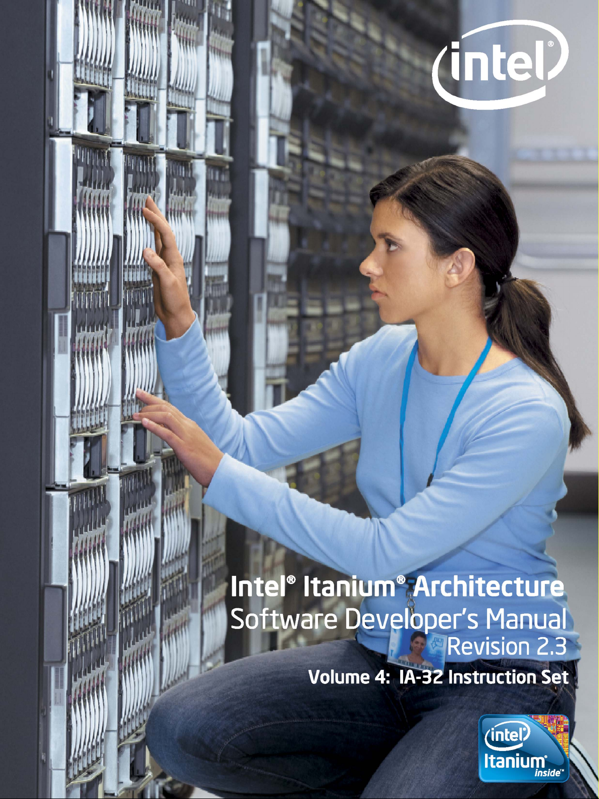
• Bit(BitBase, BitOffset) – Returns the value of a bit within a bit string, which is a
sequence of bits in memory or a register. Bits are numbered from low-order to
Volume 4: Base IA-32 Instruction Reference 4:17
Page 25
high-order within registers and within memory bytes. If the base operand is a
02131
BitOffset = 21
07775 0 0
0777500
BitBase +1 BitBase BitBase -1
BitOffset = +13
BitBase BitBase -1 BitBase -2
BitOffset = -11
register, the offset can be in the range 0..31. This offset addresses a bit within the
indicated register. An example, the function Bit[EAX, 21] is illustrated in Figure 2-2.
Figure 2-2. Bit Offset for BIT[EAX,21]
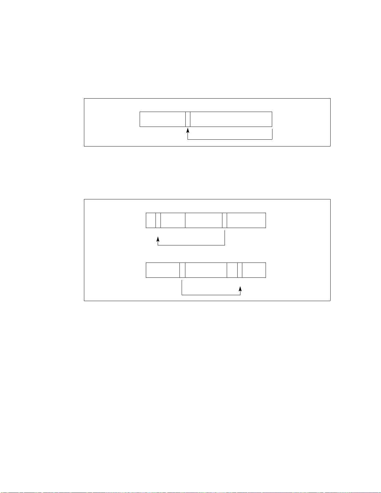
If BitBase is a memory address, BitOffset can range from -2 GBits to 2 GBits. The
addressed bit is numbered (Offset MOD 8) within the byte at address (BitBase +
(BitOffset DIV 8)), where DIV is signed division with rounding towards negative infinity,
and MOD returns a positive number. This operation is illustrated in Figure 2-3.
Figure 2-3. Memory Bit Indexing
2.2.3 Flags Affected
The “Flags Affected” section lists the flags in the EFLAGS register that are affected by
the instruction. When a flag is cleared, it is equal to 0; when it is set, it is equal to 1.
The arithmetic and logical instructions usually assign values to the status flags in a
uniform manner (see Appendix A, EFLAGS Cross-Reference, in the Intel Architecture
Software Developer’s Manual, Volume 1). Non-conventional assignments are described
in the “Operation” section. The values of flags listed as undefined may be changed by
the instruction in an indeterminate manner. Flags that are not listed are unchanged by
the instruction.
2.2.4 FPU Flags Affected
The floating-point instructions have an “FPU Flags Affected” section that describes how
4:18 Volume 4: Base IA-32 Instruction Reference
each instruction can affect the four condition code flags of the FPU status word.
Page 26

2.2.5 Protected Mode Exceptions
The “Protected Mode Exceptions” section lists the exceptions that can occur when the
instruction is executed in protected mode and the reasons for the exceptions. Each
exception is given a mnemonic that consists of a pound sign (#) followed by two letters
and an optional error code in parentheses. For example, #GP(0) denotes a general
protection exception with an error code of 0. Tab l e 2 - 2 associates each two-letter
mnemonic with the corresponding interrupt vector number and exception name. See
Chapter 5, Interrupt and Exception Handling, in the Intel Architecture Software
Developer’s Manual, Volume 3, for a detailed description of the exceptions.
Application programmers should consult the documentation provided with their
operating systems to determine the actions taken when exceptions occur.
2.2.6 Real-address Mode Exceptions
The “Real-Address Mode Exceptions” section lists the exceptions that can occur when
the instruction is executed in real-address mode.
Table 2-2. Exception Mnemonics, Names, and Vector Numbers
Vector
No.
a. The UD2 instruction was introduced in the Pentium® Pro processor.
b. This exception was introduced in the Intel® 486 processor.
c. This exception was introduced in the Pentium processor and enhanced in the Pentium Pro processor.
Mnemonic Name Source
0 #DE Divide Error DIV and IDIV instructions.
1 #DB Debug Any code or data reference.
3 #BP Breakpoint INT 3 instruction.
4 #OF Overflow INTO instruction.
5 #BR BOUND Range Exceeded BOUND instruction.
6 #UD Invalid Opcode (Undefined Opcode) UD2 instruction or reserved opcode.
7 #NM Device Not Available (No Math
Coprocessor)
8 #DF Double Fault Any instruction that can generate an
10 #TS Invalid TSS Task switch or TSS access.
11 #NP Segment Not Present Loading segment registers or accessing
12 #SS Stack Segment Fault Stack operations and SS register loads.
13 #GP General Protection Any memory reference and other protection
14 #PF Page Fault Any memory reference.
16 #MF Floating-point Error (Math Fault) Floating-point or WAIT/FWAIT instruction.
17 #AC Alignment Check Any data reference in memory.
18 #MC Machine Check Model dependent.
Floating-point or WAIT/FWAIT instruction.
exception, an NMI, or an INTR.
system segments.
checks.
c
a
b
2.2.7 Virtual-8086 Mode Exceptions
The “Virtual-8086 Mode Exceptions” section lists the exceptions that can occur when
the instruction is executed in virtual-8086 mode.
Volume 4: Base IA-32 Instruction Reference 4:19
Page 27

2.2.8 Floating-point Exceptions
The “Floating-point Exceptions” section lists additional exceptions that can occur when
a floating-point instruction is executed in any mode. All of these exception conditions
result in a floating-point error exception (#MF, vector number 16) being generated.
Tab le 2 -3 associates each one- or two-letter mnemonic with the corresponding
exception name. See “Floating-Point Exception Conditions” in Chapter 7 of the Intel
Architecture Software Developer’s Manual, Volume 1, for a detailed description of these
exceptions.
Table 2-3. Floating-point Exception Mnemonics and Names
Vector
No.
16
16 #Z Floating-point divide-by-zero FPU divide-by-zero
16 #D Floating-point denormalized operation Attempting to operate on a denormal
16 #O Floating-point numeric overflow FPU numeric overflow
16 #U Floating-point numeric underflow FPU numeric underflow
16 #P Floating-point inexact result (precision) Inexact result (precision)
Mnemonic Name Source
Floating-point invalid operation:
#IS
#IA
- Stack overflow or underflow
- Invalid arithmetic operation
- FPU stack overflow or underflow
- Invalid FPU arithmetic operation
number
2.3 IA-32 Base Instruction Reference
The remainder of this chapter provides detailed descriptions of each of the Intel
architecture instructions.
4:20 Volume 4: Base IA-32 Instruction Reference
Page 28

AAA—ASCII Adjust After Addition
Opcode Instruction Description
37 AAA ASCII adjust AL after addition
Description
Adjusts the sum of two unpacked BCD values to create an unpacked BCD result. The AL
register is the implied source and destination operand for this instruction. The AAA
instruction is only useful when it follows an ADD instruction that adds (binary addition)
two unpacked BCD values and stores a byte result in the AL register. The AAA
instruction then adjusts the contents of the AL register to contain the correct 1-digit
unpacked BCD result.
If the addition produces a decimal carry, the AH register is incremented by 1, and the
CF and AF flags are set. If there was no decimal carry, the CF and AF flags are cleared
and the AH register is unchanged. In either case, bits 4 through 7 of the AL register are
cleared to 0.
Operation
IF ((AL AND FH) > 9) OR (AF = 1)
THEN
AL (AL + 6);
AH AH + 1;
AF 1;
CF 1;
ELSE
AF 0;
CF 0;
FI;
AL AL AND FH;
Flags Affected
The AF and CF flags are set to 1 if the adjustment results in a decimal carry; otherwise
they are cleared to 0. The OF, SF, ZF, and PF flags are undefined.
Additional Itanium System Environment Exceptions
Itanium Reg Faults NaT Register Consumption Abort.
Exceptions (All Operating Modes)
None.
Volume 4: Base IA-32 Instruction Reference 4:21
Page 29

AAD—ASCII Adjust AX Before Division
Opcode Instruction Description
D5 0A AAD ASCII adjust AX before division
Description
Adjusts two unpacked BCD digits (the least-significant digit in the AL register and the
most-significant digit in the AH register) so that a division operation performed on the
result will yield a correct unpacked BCD value. The AAD instruction is only useful when
it precedes a DIV instruction that divides (binary division) the adjusted value in the AL
register by an unpacked BCD value.
The AAD instruction sets the value in the AL register to (AL + (10 * AH)), and then
clears the AH register to 00H. The value in the AX register is then equal to the binary
equivalent of the original unpacked two-digit number in registers AH and AL.
Operation
tempAL AL;
tempAH AH;
AL (tempAL + (tempAH imm8)) AND FFH;
AH 0
The immediate value (imm8) is taken from the second byte of the instruction, which
under normal assembly is 0AH (10 decimal). However, this immediate value can be
changed to produce a different result.
Flags Affected
The SF, ZF, and PF flags are set according to the result; the OF, AF, and CF flags are
undefined.
Additional Itanium System Environment Exceptions
Itanium Reg Faults NaT Register Consumption Abort.
Exceptions (All Operating Modes)
None.
4:22 Volume 4: Base IA-32 Instruction Reference
Page 30

AAM—ASCII Adjust AX After Multiply
Opcode Instruction Description
D4 0A AAM ASCII adjust AX after multiply
Description
Adjusts the result of the multiplication of two unpacked BCD values to create a pair of
unpacked BCD values. The AX register is the implied source and destination operand for
this instruction. The AAM instruction is only useful when it follows an MUL instruction
that multiplies (binary multiplication) two unpacked BCD values and stores a word
result in the AX register. The AAM instruction then adjusts the contents of the AX
register to contain the correct 2-digit unpacked BCD result.
Operation
tempAL AL;
AH tempAL / imm8;
AL tempAL MOD imm8;
The immediate value (imm8) is taken from the second byte of the instruction, which
under normal assembly is 0AH (10 decimal). However, this immediate value can be
changed to produce a different result.
Flags Affected
The SF, ZF, and PF flags are set according to the result. The OF, AF, and CF flags are
undefined.
Additional Itanium System Environment Exceptions
Itanium Reg Faults NaT Register Consumption Abort.
Exceptions (All Operating Modes)
None.
Volume 4: Base IA-32 Instruction Reference 4:23
Page 31

AAS—ASCII Adjust AL After Subtraction
Opcode Instruction Description
3F AAS ASCII adjust AL after subtraction
Description
Adjusts the result of the subtraction of two unpacked BCD values to create a unpacked
BCD result. The AL register is the implied source and destination operand for this
instruction. The AAS instruction is only useful when it follows a SUB instruction that
subtracts (binary subtraction) one unpacked BCD value from another and stores a byte
result in the AL register. The AAA instruction then adjusts the contents of the AL
register to contain the correct 1-digit unpacked BCD result.
If the subtraction produced a decimal carry, the AH register is decremented by 1, and
the CF and AF flags are set. If no decimal carry occurred, the CF and AF flags are
cleared, and the AH register is unchanged. In either case, the AL register is left with its
top nibble set to 0.
Operation
IF ((AL AND FH) > 9) OR (AF = 1)
THEN
AL AL - 6;
AH AH - 1;
AF 1;
CF 1;
ELSE
CF 0;
AF 0;
FI;
AL AL AND FH;
Flags Affected
The AF and CF flags are set to 1 if there is a decimal borrow; otherwise, they are
cleared to 0. The OF, SF, ZF, and PF flags are undefined.
Additional Itanium System Environment Exceptions
Itanium Reg Faults NaT Register Consumption Abort.
Exceptions (All Operating Modes)
None.
4:24 Volume 4: Base IA-32 Instruction Reference
Page 32

ADC—Add with Carry
Opcode Instruction Description
14 ib ADC AL,imm8 Add with carry imm8 to AL
15 iw ADC AX,imm16 Add with carry imm16 to AX
15 id ADC EAX,imm32 Add with carry imm32 to EAX
80 /2 ib ADC r/m8,imm8 Add with carry imm8 to r/m8
81 /2 iw ADC r/m16,imm16 Add with carry imm16 to r/m16
81 /2 id ADC r/m32,imm32 Add with CF imm32 to r/m32
83 /2 ib ADC r/m16,imm8 Add with CF sign-extended imm8 to r/m16
83 /2 ib ADC r/m32,imm8 Add with CF sign-extended imm8 into r/m32
10 /r ADC r/m8,r8 Add with carry byte register to r/m8
11 / r ADC r/m16,r16 Add with carry r16 to r/m16
11 / r ADC r/m32,r32 Add with CF r32 to r/m32
12 /r ADC r8,r/m8 Add with carry r/m8 to byte register
13 /r ADC r16,r/m16 Add with carry r/m16 to r16
13 /r ADC r32,r
Description
Adds the destination operand (first operand), the source operand (second operand),
and the carry (CF) flag and stores the result in the destination operand. The destination
operand can be a register or a memory location; the source operand can be an
immediate, a register, or a memory location. The state of the CF flag represents a carry
from a previous addition. When an immediate value is used as an operand, it is
sign-extended to the length of the destination operand format.
/m32 Add with CF r/m32 to r32
The ADC instruction does not distinguish between signed or unsigned operands.
Instead, the processor evaluates the result for both data types and sets the OF and CF
flags to indicate a carry in the signed or unsigned result, respectively. The SF flag
indicates the sign of the signed result.
The ADC instruction is usually executed as part of a multibyte or multiword addition in
which an ADD instruction is followed by an ADC instruction.
Operation
DEST DEST + SRC + CF;
Flags Affected
The OF, SF, ZF, AF, CF, and PF flags are set according to the result.
Additional Itanium System Environment Exceptions
Itanium Reg Faults NaT Register Consumption Abort.
Itanium Mem FaultsVHPT Data Fault, Nested TLB Fault, Data TLB Fault, Alternate Data
TLB Fault, Data Page Not Present Fault, Data NaT Page Consumption
Abort, Data Key Miss Fault, Data Key Permission Fault, Data Access
Rights Fault, Data Access Bit Fault, Data Dirty Bit Fault
Volume 4: Base IA-32 Instruction Reference 4:25
Page 33

ADC—Add with Carry (Continued)
Protected Mode Exceptions
#GP(0) If the destination is located in a nonwritable segment.
If a memory operand effective address is outside the CS, DS, ES, FS,
or GS segment limit.
If the DS, ES, FS, or GS register is used to access memory and it
contains a null segment selector.
#SS(0) If a memory operand effective address is outside the SS segment
#PF(fault-code) If a page fault occurs.
#AC(0) If alignment checking is enabled and an unaligned memory
Real Address Mode Exceptions
#GP If a memory operand effective address is outside the CS, DS, ES, FS,
#SS If a memory operand effective address is outside the SS segment
Virtual 8086 Mode Exceptions
#GP(0) If a memory operand effective address is outside the CS, DS, ES, FS,
#SS(0) If a memory operand effective address is outside the SS segment
#PF(fault-code) If a page fault occurs.
#AC(0) If alignment checking is enabled and an unaligned memory
limit.
reference is made while the current privilege level is 3.
or GS segment limit.
limit.
or GS segment limit.
limit.
reference is made.
4:26 Volume 4: Base IA-32 Instruction Reference
Page 34

ADD—Add
Opcode Instruction Description
04 ib ADD AL,imm8 Add imm8 to AL
05 iw ADD AX,imm16 Add imm16 to AX
05 id ADD EAX,imm32 Add imm32 to EAX
80 /0 ib ADD r/m8,imm8 Add imm8 to r/m8
81 /0 iw ADD r/m16,imm16 Add imm16 to r/m16
81 /0 id ADD r/m32,imm32 Add imm32 to r/m32
83 /0 ib ADD r/m16,imm8 Add sign-extended imm8 to r/m16
83 /0 ib ADD r/m32,imm8 Add sign-extended imm8 to r/m32
00 /r ADD r/m8,r8 Add r8 to r/m8
01 /r ADD r/m16,r16 Add r16 to r/m16
01 /r ADD r/m32,r32 Add r32 to r/m32
02 /r ADD r8,r/m8 Add r/m8 to r8
03 /r ADD r16,r/m16 Add r/m16 to r16
03 /r ADD r
32,r/m32 Add r/m32 to r32
Description
Adds the first operand (destination operand) and the second operand (source operand)
and stores the result in the destination operand. The destination operand can be a
register or a memory location; the source operand can be an immediate, a register, or a
memory location. When an immediate value is used as an operand, it is sign-extended
to the length of the destination operand format.
The ADD instruction does not distinguish between signed or unsigned operands.
Instead, the processor evaluates the result for both data types and sets the OF and CF
flags to indicate a carry in the signed or unsigned result, respectively. The SF flag
indicates the sign of the signed result.
Operation
DEST DEST + SRC;
Flags Affected
The OF, SF, ZF, AF, CF, and PF flags are set according to the result.
Additional Itanium System Environment Exceptions
Itanium Reg Faults NaT Register Consumption Abort.
Itanium Mem FaultsVHPT Data Fault, Nested TLB Fault, Data TLB Fault, Alternate Data
TLB Fault, Data Page Not Present Fault, Data NaT Page Consumption
Abort, Data Key Miss Fault, Data Key Permission Fault, Data Access
Rights Fault, Data Access Bit Fault, Data Dirty Bit Fault
Volume 4: Base IA-32 Instruction Reference 4:27
Page 35

ADD—Add (Continued)
Protected Mode Exceptions
#GP(0) If the destination is located in a nonwritable segment.
#PF(fault-code) If a page fault occurs.
#AC(0) If alignment checking is enabled and an unaligned memory
Real Address Mode Exceptions
#GP If a memory operand effective address is outside the CS, DS, ES, FS,
#SS If a memory operand effective address is outside the SS segment
Virtual 8086 Mode Exceptions
#GP(0) If a memory operand effective address is outside the CS, DS, ES, FS,
#SS(0) If a memory operand effective address is outside the SS segment
#PF(fault-code) If a page fault occurs.
#AC(0) If alignment checking is enabled and an unaligned memory
If a memory operand effective address is outside the CS, DS, ES, FS,
or GS segment limit.
If the DS, ES, FS, or GS register is used to access memory and it
contains a null segment selector.
#SS(0)If a memory operand effective address is outside the SS
segment limit.
reference is made while the current privilege level is 3.
or GS segment limit.
limit.
or GS segment limit.
limit.
reference is made.
4:28 Volume 4: Base IA-32 Instruction Reference
Page 36

AND—Logical AND
Opcode Instruction Description
24 ib AND AL,imm8 AL AND imm8
25 iw AND AX,imm16 AX AND imm16
25 id AND EAX,imm32 EAX AND imm32
80 /4 ib AND r/m8,imm8 r/m8 AND imm8
81 /4 iw AND r/m16,imm16 r/m16 AND imm16
81 /4 id AND r/m32,imm32 r/m32 AND imm32
83 /4 ib AND r/m16,imm8 r/m16 AND imm8
83 /4 ib AND r/m32,imm8 r/m32 AND imm8
20 /r AND r/m8,r8 r/m8 AND r8
21 /r AND r/m16,r16 r/m16 AND r16
21 /r AND r/m32,r32 r/m32 AND r32
22 /r AND r8,r/m8 r8 AND r/m8
23 /r AND r16,r/m16 r16 AND r/m16
23 /r AND r32,r/m32 r32 AND r/m32
Description
Performs a bitwise AND operation on the destination (first) and source (second)
operands and stores the result in the destination operand location. The source operand
can be an immediate, a register, or a memory location; the destination operand can be
a register or a memory location.
Operation
DEST DEST AND SRC;
Flags Affected
The OF and CF flags are cleared; the SF, ZF, and PF flags are set according to the result.
The state of the AF flag is undefined.
Additional Itanium System Environment Exceptions
Itanium Reg Faults NaT Register Consumption Abort.
Itanium Mem FaultsVHPT Data Fault, Nested TLB Fault, Data TLB Fault, Alternate Data
TLB Fault, Data Page Not Present Fault, Data NaT Page Consumption
Abort, Data Key Miss Fault, Data Key Permission Fault, Data Access
Rights Fault, Data Access Bit Fault, Data Dirty Bit Fault
Protected Mode Exceptions
#GP(0) If the destination operand points to a nonwritable segment.
If a memory operand effective address is outside the CS, DS, ES, FS,
or GS segment limit.
If the DS, ES, FS, or GS register contains a null segment selector.
#SS(0) If a memory operand effective address is outside the SS segment
limit.
Volume 4: Base IA-32 Instruction Reference 4:29
Page 37

AND—Logical AND (Continued)
#PF(fault-code) If a page fault occurs.
#AC(0) If alignment checking is enabled and an unaligned memory
Real Address Mode Exceptions
#GP If a memory operand effective address is outside the CS, DS, ES, FS,
#SS If a memory operand effective address is outside the SS segment
Virtual 8086 Mode Exceptions
#GP(0) If a memory operand effective address is outside the CS, DS, ES, FS,
#SS(0) If a memory operand effective address is outside the SS segment
#PF(fault-code) If a page fault occurs.
#AC(0) If alignment checking is enabled and an unaligned memory
reference is made while the current privilege level is 3.
or GS segment limit.
limit.
or GS segment limit.
limit.
reference is made.
4:30 Volume 4: Base IA-32 Instruction Reference
Page 38

ARPL—Adjust RPL Field of Segment Selector
Opcode Instruction Description
63 /r ARPL r/m16,r16 Adjust RPL of r/m16 to not less than RPL of r16
Description
Compares the RPL fields of two segment selectors. The first operand (the destination
operand) contains one segment selector and the second operand (source operand)
contains the other. (The RPL field is located in bits 0 and 1 of each operand.) If the RPL
field of the destination operand is less than the RPL field of the source operand, the ZF
flag is set and the RPL field of the destination operand is increased to match that of the
source operand. Otherwise, the ZF flag is cleared and no change is made to the
destination operand. (The destination operand can be a word register or a memory
location; the source operand must be a word register.)
The ARPL instruction is provided for use by operating-system procedures (however, it
can also be used by applications). It is generally used to adjust the RPL of a segment
selector that has been passed to the operating system by an application program to
match the privilege level of the application program. Here the segment selector passed
to the operating system is placed in the destination operand and segment selector for
the application program’s code segment is placed in the source operand. (The RPL field
in the source operand represents the privilege level of the application program.)
Execution of the ARPL instruction then insures that the RPL of the segment selector
received by the operating system is no lower (does not have a higher privilege) than
the privilege level of the application program. (The segment selector for the application
program’s code segment can be read from the procedure stack following a procedure
call.)
See the Intel Architecture Software Developer’s Manual, Volume 3 for more information
about the use of this instruction.
Operation
IF DEST(RPL) < SRC(RPL)
THEN
ZF 1;
DEST(RPL) SRC(RPL);
ELSE
ZF 0;
FI;
Flags Affected
The ZF flag is set to 1 if the RPL field of the destination operand is less than that of the
source operand; otherwise, is cleared to 0.
Volume 4: Base IA-32 Instruction Reference 4:31
Page 39

ARPL—Adjust RPL Field of Segment Selector (Continued)
Additional Itanium System Environment Exceptions
Itanium Reg Faults NaT Register Consumption Abort.
Itanium Mem FaultsVHPT Data Fault, Nested TLB Fault, Data TLB Fault, Alternate Data
Protected Mode Exceptions
#GP(0) If the destination is located in a nonwritable segment.
#SS(0) If a memory operand effective address is outside the SS segment
#PF(fault-code) If a page fault occurs.
#AC(0) If alignment checking is enabled and an unaligned memory
Real Address Mode Exceptions
#UD The ARPL instruction is not recognized in real address mode.
TLB Fault, Data Page Not Present Fault, Data NaT Page Consumption
Abort, Data Key Miss Fault, Data Key Permission Fault, Data Access
Rights Fault, Data Access Bit Fault, Data Dirty Bit Fault
If a memory operand effective address is outside the CS, DS, ES, FS,
or GS segment limit.
If the DS, ES, FS, or GS register is used to access memory and it
contains a null segment selector.
limit.
reference is made while the current privilege level is 3.
Virtual 8086 Mode Exceptions
#UD The ARPL instruction is not recognized in virtual 8086 mode.
4:32 Volume 4: Base IA-32 Instruction Reference
Page 40

BOUND—Check Array Index Against Bounds
Opcode Instruction Description
62 /r BOUND r16,m16&16 Check if r16 (array index) is within bounds specified by m16&16
62 /r BOUND r32,m32&32 Check if r32 (array index) is within bounds specified by m16&16
Description
Determines if the first operand (array index) is within the bounds of an array specified
the second operand (bounds operand). The array index is a signed integer located in a
register. The bounds operand is a memory location that points to a pair of signed
doubleword-integers (when the operand-size attribute is 32) or a pair of signed
word-integers (when the operand-size attribute is 16). The first doubleword (or word)
is the lower bound of the array and the second doubleword (or word) is the upper
bound of the array. The array index must be greater than or equal to the lower bound
and less than or equal to the upper bound plus the operand size in bytes. If the index is
not within bounds, a BOUND range exceeded exception (#BR) is signaled. (When a this
exception is generated, the saved return instruction pointer points to the BOUND
instruction.)
The bounds limit data structure (two words or doublewords containing the lower and
upper limits of the array) is usually placed just before the array itself, making the limits
addressable via a constant offset from the beginning of the array. Because the address
of the array already will be present in a register, this practice avoids extra bus cycles to
obtain the effective address of the array bounds.
Operation
IF (ArrayIndex < LowerBound OR ArrayIndex > (UppderBound + OperandSize/8]))
(* Below lower bound or above upper bound *)
THEN
#BR;
FI;
Flags Affected
None.
Additional Itanium System Environment Exceptions
Itanium Reg Faults NaT Register Consumption Abort.
Itanium Mem FaultsVHPT Data Fault, Nested TLB Fault, Data TLB Fault, Alternate Data
TLB Fault, Data Page Not Present Fault, Data NaT Page Consumption
Abort, Data Key Miss Fault, Data Key Permission Fault, Data Access
Rights Fault, Data Access Bit Fault, Data Dirty Bit Fault
Volume 4: Base IA-32 Instruction Reference 4:33
Page 41

BOUND—Check Array Index Against Bounds (Continued)
Protected Mode Exceptions
#BR If the bounds test fails.
#UD If second operand is not a memory location.
#GP(0) If a memory operand effective address is outside the CS, DS, ES, FS,
#SS(0) If a memory operand effective address is outside the SS segment
#PF(fault-code) If a page fault occurs.
#AC(0) If alignment checking is enabled and an unaligned memory
Real Address Mode Exceptions
#BR If the bounds test fails.
#GP If a memory operand effective address is outside the CS, DS, ES, FS,
#SS If a memory operand effective address is outside the SS segment
Virtual 8086 Mode Exceptions
#BR If the bounds test fails.
#GP(0) If a memory operand effective address is outside the CS, DS, ES, FS,
#SS(0) If a memory operand effective address is outside the SS segment
#PF(fault-code) If a page fault occurs.
#AC(0) If alignment checking is enabled and an unaligned memory
or GS segment limit.
If the DS, ES, FS, or GS register contains a null segment selector.
limit.
reference is made while the current privilege level is 3.
or GS segment limit.
limit.
or GS segment limit.
limit.
reference is made.
4:34 Volume 4: Base IA-32 Instruction Reference
Page 42

BSF—Bit Scan Forward
Opcode Instruction Description
0F BC BSF r16,r/m16 Bit scan forward on r/m16
0F BC BSF r32,r/m32 Bit scan forward on r/m32
Description
Searches the source operand (second operand) for the least significant set bit (1 bit). If
a least significant 1 bit is found, its bit index is stored in the destination operand (first
operand). The source operand can be a register or a memory location; the destination
operand is a register. The bit index is an unsigned offset from bit 0 of the source
operand. If the contents source operand are 0, the contents of the destination operand
is undefined.
Operation
IF SRC = 0
THEN
ZF 1;
DEST is undefined;
ELSE
ZF 0;
temp 0;
WHILE Bit(SRC, temp) = 0
DO
temp temp + 1;
DEST temp;
OD;
FI;
Flags Affected
The ZF flag is set to 1 if all the source operand is 0; otherwise, the ZF flag is cleared.
The CF, OF, SF, AF, and PF, flags are undefined.
Additional Itanium System Environment Exceptions
Itanium Reg Faults NaT Register Consumption Abort.
Itanium Mem FaultsVHPT Data Fault, Nested TLB Fault, Data TLB Fault, Alternate Data
Volume 4: Base IA-32 Instruction Reference 4:35
TLB Fault, Data Page Not Present Fault, Data NaT Page Consumption
Abort, Data Key Miss Fault, Data Key Permission Fault, Data Access
Rights Fault, Data Access Bit Fault, Data Dirty Bit Fault
Page 43

BSF—Bit Scan Forward (Continued)
Protected Mode Exceptions
#GP(0) If a memory operand effective address is outside the CS, DS, ES, FS,
#SS(0) If a memory operand effective address is outside the SS segment
#PF(fault-code) If a page fault occurs.
#AC(0) If alignment checking is enabled and an unaligned memory
Real Address Mode Exceptions
#GP If a memory operand effective address is outside the CS, DS, ES, FS,
#SS If a memory operand effective address is outside the SS segment
Virtual 8086 Mode Exceptions
#GP(0) If a memory operand effective address is outside the CS, DS, ES, FS,
#SS(0) If a memory operand effective address is outside the SS segment
#PF(fault-code) If a page fault occurs.
#AC(0) If alignment checking is enabled and an unaligned memory
or GS segment limit.
If the DS, ES, FS, or GS register contains a null segment selector.
limit.
reference is made while the current privilege level is 3.
or GS segment limit.
limit.
or GS segment limit.
limit.
reference is made.
4:36 Volume 4: Base IA-32 Instruction Reference
Page 44

BSR—Bit Scan Reverse
Opcode Instruction Description
0F BD BSR r16,r/m16 Bit scan reverse on r/m16
0F BD BSR r32,r/m32 Bit scan reverse on r/m32
Description
Searches the source operand (second operand) for the most significant set bit (1 bit). If
a most significant 1 bit is found, its bit index is stored in the destination operand (first
operand). The source operand can be a register or a memory location; the destination
operand is a register. The bit index is an unsigned offset from bit 0 of the source
operand. If the contents source operand are 0, the contents of the destination operand
is undefined.
Operation
IF SRC = 0
THEN
ZF 1;
DEST is undefined;
ELSE
ZF 0;
temp OperandSize - 1;
WHILE Bit(SRC, temp) = 0
DO
temp temp 1;
DEST temp;
OD;
FI;
Flags Affected
The ZF flag is set to 1 if all the source operand is 0; otherwise, the ZF flag is cleared.
The CF, OF, SF, AF, and PF, flags are undefined.
Additional Itanium System Environment Exceptions
Itanium Reg Faults NaT Register Consumption Abort.
Itanium Mem FaultsVHPT Data Fault, Nested TLB Fault, Data TLB Fault, Alternate Data
Volume 4: Base IA-32 Instruction Reference 4:37
TLB Fault, Data Page Not Present Fault, Data NaT Page Consumption
Abort, Data Key Miss Fault, Data Key Permission Fault, Data Access
Rights Fault, Data Access Bit Fault, Data Dirty Bit Fault
Page 45

BSR—Bit Scan Reverse (Continued)
Protected Mode Exceptions
#GP(0) If a memory operand effective address is outside the CS, DS, ES, FS,
#SS(0) If a memory operand effective address is outside the SS segment
#PF(fault-code) If a page fault occurs.
#AC(0) If alignment checking is enabled and an unaligned memory
Real Address Mode Exceptions
#GP If a memory operand effective address is outside the CS, DS, ES, FS,
#SS If a memory operand effective address is outside the SS segment
Virtual 8086 Mode Exceptions
#GP(0) If a memory operand effective address is outside the CS, DS, ES, FS,
#SS(0) If a memory operand effective address is outside the SS segment
#PF(fault-code) If a page fault occurs.
#AC(0) If alignment checking is enabled and an unaligned memory
or GS segment limit.
If the DS, ES, FS, or GS register contains a null segment selector.
limit.
reference is made while the current privilege level is 3.
or GS segment limit.
limit.
or GS segment limit.
limit.
reference is made.
4:38 Volume 4: Base IA-32 Instruction Reference
Page 46

BSWAP—Byte Swap
Opcode Instruction Description
0F C8+rd BSWAP r32 Reverses the byte order of a 32-bit register.
Description
Reverses the byte order of a 32-bit (destination) register: bits 0 through 7 are swapped
with bits 24 through 31, and bits 8 through 15 are swapped with bits 16 through 23.
This instruction is provided for converting little-endian values to big-endian format and
vice versa.
To swap bytes in a word value (16-bit register), use the XCHG instruction. When the
BSWAP instruction references a 16-bit register, the result is undefined.
Operation
TEMP DEST
DEST(7..0) TEMP(31..24)
DEST(15..8) TEMP(23..16)
DEST(23..16) TEMP(15..8)
DEST(31..24) TEMP(7..0)
Flags Affected
None.
Additional Itanium System Environment Exceptions
Itanium Reg Faults NaT Register Consumption Abort.
Exceptions (All Operating Modes)
None.
Intel Architecture Compatibility Information
The BSWAP instruction is not supported on Intel architecture processors earlier than
the Intel486™ processor family. For compatibility with this instruction, include
functionally-equivalent code for execution on Intel processors earlier than the Intel486
processor family.
Volume 4: Base IA-32 Instruction Reference 4:39
Page 47

BT—Bit Test
Opcode Instruction Description
0F A3 BT r/m16,r16 Store selected bit in CF flag
0F A3 BT r/m32,r32 Store selected bit in CF flag
0F BA /4 ib BT r/m16,imm8 Store selected bit in CF flag
0F BA /4 ib BT r/m32,imm8 Store selected bit in CF flag
Description
Selects the bit in a bit string (specified with the first operand, called the bit base) at the
bit-position designated by the bit offset operand (second operand) and stores the value
of the bit in the CF flag. The bit base operand can be a register or a memory location;
the bit offset operand can be a register or an immediate value. If the bit base operand
specifies a register, the instruction takes the modulo 16 or 32 (depending on the
register size) of the bit offset operand, allowing any bit position to be selected in a 16or 32-bit register, respectively. If the bit base operand specifies a memory location, it
represents the address of the byte in memory that contains the bit base (bit 0 of the
specified byte) of the bit string. The offset operand then selects a bit position within the
range 2
Some assemblers support immediate bit offsets larger than 31 by using the immediate
bit offset field in combination with the displacement field of the memory operand. In
this case, the low-order 3 or 5 bits (3 for 16-bit operands, 5 for 32-bit operands) of the
immediate bit offset are stored in the immediate bit offset field, and the high-order bits
are shifted and combined with the byte displacement in the addressing mode by the
assembler. The processor will ignore the high order bits if they are not zero.
31
to 231 1 for a register offset and 0 to 31 for an immediate offset.
When accessing a bit in memory, the processor may access 4 bytes starting from the
memory address for a 32-bit operand size, using by the following relationship:
Effective Address + (4 (BitOffset DIV 32))
Or, it may access 2 bytes starting from the memory address for a 16-bit operand, using
this relationship:
Effective Address + (2 (BitOffset DIV 16))
It may do so even when only a single byte needs to be accessed to reach the given bit.
When using this bit addressing mechanism, software should avoid referencing areas of
memory close to address space holes. In particular, it should avoid references to
memory-mapped I/O registers. Instead, software should use the MOV instructions to
load from or store to these addresses, and use the register form of these instructions to
manipulate the data.
Operation
CF Bit(BitBase, BitOffset)
Flags Affected
The CF flag contains the value of the selected bit. The OF, SF, ZF, AF, and PF flags are
undefined.
4:40 Volume 4: Base IA-32 Instruction Reference
Page 48

BT—Bit Test (Continued)
Additional Itanium System Environment Exceptions
Itanium Reg Faults NaT Register Consumption Abort.
Itanium Mem FaultsVHPT Data Fault, Nested TLB Fault, Data TLB Fault, Alternate Data
Protected Mode Exceptions
#GP(0) If a memory operand effective address is outside the CS, DS, ES, FS,
#SS(0) If a memory operand effective address is outside the SS segment
#PF(fault-code) If a page fault occurs.
#AC(0) If alignment checking is enabled and an unaligned memory
Real Address Mode Exceptions
#GP If a memory operand effective address is outside the CS, DS, ES, FS,
#SS If a memory operand effective address is outside the SS segment
TLB Fault, Data Page Not Present Fault, Data NaT Page Consumption
Abort, Data Key Miss Fault, Data Key Permission Fault, Data Access
Rights Fault, Data Access Bit Fault, Data Dirty Bit Fault
or GS segment limit.
If the DS, ES, FS, or GS register contains a null segment selector.
limit.
reference is made while the current privilege level is 3.
or GS segment limit.
limit.
Virtual 8086 Mode Exceptions
#GP(0) If a memory operand effective address is outside the CS, DS, ES, FS,
#SS(0) If a memory operand effective address is outside the SS segment
#PF(fault-code) If a page fault occurs.
#AC(0) If alignment checking is enabled and an unaligned memory
or GS segment limit.
limit.
reference is made.
Volume 4: Base IA-32 Instruction Reference 4:41
Page 49

BTC—Bit Test and Complement
Opcode Instruction Description
0F BB BTC r/m16,r16 Store selected bit in CF flag and complement
0F BB BTC r/m32,r32 Store selected bit in CF flag and complement
0F BA /7 ib BTC r/m16,imm8 Store selected bit in CF flag and complement
0F BA /7 ib BTC r/m32,imm8 Store selected bit in CF flag and complement
Description
Selects the bit in a bit string (specified with the first operand, called the bit base) at the
bit-position designated by the bit offset operand (second operand), stores the value of
the bit in the CF flag, and complements the selected bit in the bit string. The bit base
operand can be a register or a memory location; the bit offset operand can be a register
or an immediate value. If the bit base operand specifies a register, the instruction takes
the modulo 16 or 32 (depending on the register size) of the bit offset operand, allowing
any bit position to be selected in a 16- or 32-bit register, respectively. If the bit base
operand specifies a memory location, it represents the address of the byte in memory
that contains the bit base (bit 0 of the specified byte) of the bit string. The offset
operand then selects a bit position within the range 2
and 0 to 31 for an immediate offset.
Some assemblers support immediate bit offsets larger than 31 by using the immediate
bit offset field in combination with the displacement field of the memory operand. See
“BT—Bit Test” on page 4:40 for more information on this addressing mechanism.
31
to 231 1 for a register offset
Operation
CF Bit(BitBase, BitOffset)
Bit(BitBase, BitOffset) NOT Bit(BitBase, BitOffset);
Flags Affected
The CF flag contains the value of the selected bit before it is complemented. The OF, SF,
ZF, AF, and PF flags are undefined.
Additional Itanium System Environment Exceptions
Itanium Reg Faults NaT Register Consumption Abort.
Itanium Mem FaultsVHPT Data Fault, Nested TLB Fault, Data TLB Fault, Alternate Data
TLB Fault, Data Page Not Present Fault, Data NaT Page Consumption
Abort, Data Key Miss Fault, Data Key Permission Fault, Data Access
Rights Fault, Data Access Bit Fault, Data Dirty Bit Fault
4:42 Volume 4: Base IA-32 Instruction Reference
Page 50

BTC—Bit Test and Complement (Continued)
Protected Mode Exceptions
#GP(0) If the destination operand points to a non-writable segment.
If a memory operand effective address is outside the CS, DS, ES, FS,
or GS segment limit.
If the DS, ES, FS, or GS register contains a null segment selector.
#SS(0) If a memory operand effective address is outside the SS segment
#PF(fault-code) If a page fault occurs.
#AC(0) If alignment checking is enabled and an unaligned memory
Real Address Mode Exceptions
#GP If a memory operand effective address is outside the CS, DS, ES, FS,
#SS If a memory operand effective address is outside the SS segment
Virtual 8086 Mode Exceptions
#GP(0) If a memory operand effective address is outside the CS, DS, ES, FS,
#SS(0) If a memory operand effective address is outside the SS segment
#PF(fault-code) If a page fault occurs.
#AC(0) If alignment checking is enabled and an unaligned memory
limit.
reference is made while the current privilege level is 3.
or GS segment limit.
limit.
or GS segment limit.
limit.
reference is made.
Volume 4: Base IA-32 Instruction Reference 4:43
Page 51

BTR—Bit Test and Reset
Opcode Instruction Description
0F B3 BTR r/m16,r16 Store selected bit in CF flag and clear
0F B3 BTR r/m32,r32 Store selected bit in CF flag and clear
0F BA /6 ib BTR r/m16,imm8 Store selected bit in CF flag and clear
0F BA /6 ib BTR r/m32,imm8 Store selected bit in CF flag and clear
Description
Selects the bit in a bit string (specified with the first operand, called the bit base) at the
bit-position designated by the bit offset operand (second operand), stores the value of
the bit in the CF flag, and clears the selected bit in the bit string to 0. The bit base
operand can be a register or a memory location; the bit offset operand can be a register
or an immediate value. If the bit base operand specifies a register, the instruction takes
the modulo 16 or 32 (depending on the register size) of the bit offset operand, allowing
any bit position to be selected in a 16- or 32-bit register, respectively. If the bit base
operand specifies a memory location, it represents the address of the byte in memory
that contains the bit base (bit 0 of the specified byte) of the bit string. The offset
operand then selects a bit position within the range 2
and 0 to 31 for an immediate offset.
Some assemblers support immediate bit offsets larger than 31 by using the immediate
bit offset field in combination with the displacement field of the memory operand. See
“BT—Bit Test” on page 4:40 for more information on this addressing mechanism.
31
to 231 1 for a register offset
Operation
CF Bit(BitBase, BitOffset)
Bit(BitBase, BitOffset) 0;
Flags Affected
The CF flag contains the value of the selected bit before it is cleared. The OF, SF, ZF, AF,
and PF flags are undefined.
Additional Itanium System Environment Exceptions
Itanium Reg Faults NaT Register Consumption Abort.
Itanium Mem FaultsVHPT Data Fault, Nested TLB Fault, Data TLB Fault, Alternate Data
TLB Fault, Data Page Not Present Fault, Data NaT Page Consumption
Abort, Data Key Miss Fault, Data Key Permission Fault, Data Access
Rights Fault, Data Access Bit Fault, Data Dirty Bit Fault
4:44 Volume 4: Base IA-32 Instruction Reference
Page 52

BTR—Bit Test and Reset (Continued)
Protected Mode Exceptions
#GP(0) If the destination operand points to a nonwritable segment.
If a memory operand effective address is outside the CS, DS, ES, FS,
or GS segment limit.
If the DS, ES, FS, or GS register contains a null segment selector.
#SS(0) If a memory operand effective address is outside the SS segment
#PF(fault-code) If a page fault occurs.
#AC(0) If alignment checking is enabled and an unaligned memory
Real Address Mode Exceptions
#GP If a memory operand effective address is outside the CS, DS, ES, FS,
#SS If a memory operand effective address is outside the SS segment
Virtual 8086 Mode Exceptions
#GP(0) If a memory operand effective address is outside the CS, DS, ES, FS,
#SS(0) If a memory operand effective address is outside the SS segment
#PF(fault-code) If a page fault occurs.
#AC(0) If alignment checking is enabled and an unaligned memory
limit.
reference is made while the current privilege level is 3.
or GS segment limit.
limit.
or GS segment limit.
limit.
reference is made.
Volume 4: Base IA-32 Instruction Reference 4:45
Page 53

BTS—Bit Test and Set
Opcode Instruction Description
0F AB BTS r/m16,r16 Store selected bit in CF flag and set
0F AB BTS r/m32,r32 Store selected bit in CF flag and set
0F BA /5 ib BTS r/m16,imm8 Store selected bit in CF flag and set
0F BA /5 ib BTS r/m32,imm8 Store selected bit in CF flag and set
Description
Selects the bit in a bit string (specified with the first operand, called the bit base) at the
bit-position designated by the bit offset operand (second operand), stores the value of
the bit in the CF flag, and sets the selected bit in the bit string to 1. The bit base
operand can be a register or a memory location; the bit offset operand can be a register
or an immediate value. If the bit base operand specifies a register, the instruction takes
the modulo 16 or 32 (depending on the register size) of the bit offset operand, allowing
any bit position to be selected in a 16- or 32-bit register, respectively. If the bit base
operand specifies a memory location, it represents the address of the byte in memory
that contains the bit base (bit 0 of the specified byte) of the bit string. The offset
operand then selects a bit position within the range 2
and 0 to 31 for an immediate offset.
Some assemblers support immediate bit offsets larger than 31 by using the immediate
bit offset field in combination with the displacement field of the memory operand. See
“BT—Bit Test” on page 4:40 for more information on this addressing mechanism.
31
to 231 1 for a register offset
Operation
CF Bit(BitBase, BitOffset)
Bit(BitBase, BitOffset) 1;
Flags Affected
The CF flag contains the value of the selected bit before it is set. The OF, SF, ZF, AF, and
PF flags are undefined.
Additional Itanium System Environment Exceptions
Itanium Reg Faults NaT Register Consumption Abort.
Itanium Mem FaultsVHPT Data Fault, Nested TLB Fault, Data TLB Fault, Alternate Data
TLB Fault, Data Page Not Present Fault, Data NaT Page Consumption
Abort, Data Key Miss Fault, Data Key Permission Fault, Data Access
Rights Fault, Data Access Bit Fault, Data Dirty Bit Fault
4:46 Volume 4: Base IA-32 Instruction Reference
Page 54

BTS—Bit Test and Set (Continued)
Protected Mode Exceptions
#GP(0) If the destination operand points to a nonwritable segment.
If a memory operand effective address is outside the CS, DS, ES, FS,
or GS segment limit.
If the DS, ES, FS, or GS register contains a null segment selector.
#SS(0) If a memory operand effective address is outside the SS segment
#PF(fault-code) If a page fault occurs.
#AC(0) If alignment checking is enabled and an unaligned memory
Real Address Mode Exceptions
#GP If a memory operand effective address is outside the CS, DS, ES, FS,
#SS If a memory operand effective address is outside the SS segment
Virtual 8086 Mode Exceptions
#GP If a memory operand effective address is outside the CS, DS, ES, FS,
#SS If a memory operand effective address is outside the SS segment
#PF(fault-code) If a page fault occurs.
#AC(0) If alignment checking is enabled and an unaligned memory
limit.
reference is made while the current privilege level is 3.
or GS segment limit.
limit.
or GS segment limit.
limit.
reference is made.
Volume 4: Base IA-32 Instruction Reference 4:47
Page 55

CALL—Call Procedure
Opcode Instruction Description
E8 cw CALL rel16 Call near, displacement relative to next instruction
E8 cd CALL rel32 Call near, displacement relative to next instruction
FF /2 CALL r/m16 Call near, r/m16 indirect
FF /2 CALL r/m32 Call near, r/m32 indirect
9A cd CALL ptr16:16 Call far, to full pointer given
9A cp CALL ptr16:32 Call far, to full pointer given
FF /3 CALL m16:16 Call far, address at r/m16
FF /3 CALL m16:32 Call far, address at r/m32
Description
Saves procedure linking information on the procedure stack and jumps to the
procedure (called procedure) specified with the destination (target) operand. The target
operand specifies the address of the first instruction in the called procedure. This
operand can be an immediate value, a general-purpose register, or a memory location.
This instruction can be used to execute four different types of calls:
• Near call – A call to a procedure within the current code segment (the segment
currently pointed to by the CS register), sometimes referred to as an intrasegment
call.
• Far call – A call to a procedure located in a different segment than the current code
segment, sometimes referred to as an intersegment call.
• Inter-privilege-level far call – A far call to a procedure in a segment at a different
privilege level than that of the currently executing program or procedure. Results
in an IA-32_Intercept(Gate) in Itanium System Environment.
• Task switch – A call to a procedure located in a different task. Results in an
IA-32_Intercept(Gate) in Itanium System Environment.
The latter two call types (inter-privilege-level call and task switch) can only be executed
in protected mode. See Chapter 6 in the Intel Architecture Software Developer’s
Manual, Volume 3 for information on task switching with the CALL instruction.
When executing a near call, the processor pushes the value of the EIP register (which
contains the address of the instruction following the CALL instruction) onto the
procedure stack (for use later as a return-instruction pointer. The processor then jumps
to the address specified with the target operand for the called procedure. The target
operand specifies either an absolute address in the code segment (that is an offset from
the base of the code segment) or a relative offset (a signed offset relative to the
current value of the instruction pointer in the EIP register, which points to the
instruction following the call). An absolute address is specified directly in a register or
indirectly in a memory location (r/m16 or r/m32 target-operand form). (When
accessing an absolute address indirectly using the stack pointer (ESP) as a base
register, the base value used is the value of the ESP before the instruction executes.) A
relative offset (rel16 or rel32) is generally specified as a label in assembly code, but at
the machine code level, it is encoded as a signed, 16- or 32-bit immediate value, which
is added to the instruction pointer.
4:48 Volume 4: Base IA-32 Instruction Reference
Page 56

CALL—Call Procedure (Continued)
When executing a near call, the operand-size attribute determines the size of the target
operand (16 or 32 bits) for absolute addresses. Absolute addresses are loaded directly
into the EIP register. When a relative offset is specified, it is added to the value of the
EIP register. If the operand-size attribute is 16, the upper two bytes of the EIP register
are cleared to 0s, resulting in a maximum instruction pointer size of 16 bits. The CS
register is not changed on near calls.
When executing a far call, the processor pushes the current value of both the CS and
EIP registers onto the procedure stack for use as a return-instruction pointer. The
processor then performs a far jump to the code segment and address specified with the
target operand for the called procedure. Here the target operand specifies an absolute
far address either directly with a pointer (ptr16:16 or ptr16:32) or indirectly with a
memory location (m16:16 or m16:32). With the pointer method, the segment and
address of the called procedure is encoded in the instruction using a 4-byte (16-bit
operand size) or 6-byte (32-bit operand size) far address immediate. With the indirect
method, the target operand specifies a memory location that contains a 4-byte (16-bit
operand size) or 6-byte (32-bit operand size) far address. The operand-size attribute
determines the size of the offset (16 or 32 bits) in the far address. The far address is
loaded directly into the CS and EIP registers. If the operand-size attribute is 16, the
upper two bytes of the EIP register are cleared to 0s.
Any far call from a 32-bit code segment to a 16-bit code segment should be made from
the first 64 Kbytes of the 32-bit code segment, because the operand-size attribute of
the instruction is set to 16, allowing only a 16-bit return address offset to be saved.
Also, the call should be made using a 16-bit call gate so that 16-bit values will be
pushed on the stack.
When the processor is operating in protected mode, a far call can also be used to
access a code segment at a different privilege level or to switch tasks. Here, the
processor uses the segment selector part of the far address to access the segment
descriptor for the segment being jumped to. Depending on the value of the type and
access rights information in the segment selector, the CALL instruction can perform:
• A far call to the same privilege level (described in the previous paragraph).
• An far call to a different privilege level. Results in an IA-32_Intercept(Gate) in
Itanium System Environment.
• A task switch. Results in an IA-32_Intercept(Gate) in Itanium System
Environment.
When executing an inter-privilege-level far call, the code segment for the procedure
being called is accessed through a call gate. The segment selector specified by the
target operand identifies the call gate. In executing a call through a call gate where a
change of privilege level occurs, the processor switches to the stack for the privilege
level of the called procedure, pushes the current values of the CS and EIP registers and
the SS and ESP values for the old stack onto the new stack, then performs a far jump to
the new code segment. The new code segment is specified in the call gate descriptor;
the new stack segment is specified in the TSS for the currently running task. The jump
to the new code segment occurs after the stack switch. On the new stack, the processor
pushes the segment selector and stack pointer for the calling procedure’s stack, a set of
parameters from the calling procedures stack, and the segment selector and instruction
pointer for the calling procedure’s code segment. (A value in the call gate descriptor
determines how many parameters to copy to the new stack.)
Finally, the processor jumps to the address of the procedure being called within the new
code segment. The procedure address is the offset specified by the target operand.
Here again, the target operand can specify the far address of the call gate and
procedure either directly with a pointer (ptr16:16 or ptr16:32) or indirectly with a
memory location (m16:16 or m16:32).
Volume 4: Base IA-32 Instruction Reference 4:49
Page 57

CALL—Call Procedure (Continued)
Executing a task switch with the CALL instruction, is similar to executing a call through
a call gate. Here the target operand specifies the segment selector of the task gate for
the task being switched to and the address of the procedure being called in the task.
The task gate in turn points to the TSS for the task, which contains the segment
selectors for the task’s code and stack segments. The CALL instruction can also specify
the segment selector of the TSS directly. See the Intel Architecture Software
Developer’s Manual, Volume 3 the for detailed information on the mechanics of a task
switch.
Operation
IF near call
THEN IF near relative call
IF the instruction pointer is not within code segment limit THEN #GP(0); FI;
THEN IF OperandSize = 32
THEN
IF stack not large enough for a 4-byte return address THEN #SS(0); FI;
Push(EIP);
EIP EIP + DEST; (* DEST is rel32 *)
ELSE (* OperandSize = 16 *)
IF stack not large enough for a 2-byte return address THEN #SS(0); FI;
Push(IP);
EIP (EIP + DEST) AND 0000FFFFH; (* DEST is rel16 *)
FI;
FI;
ELSE (* near absolute call *)
IF the instruction pointer is not within code segment limit THEN #GP(0); FI;
IF OperandSize = 32
THEN
IF stack not large enough for a 4-byte return address THEN #SS(0); FI;
Push(EIP);
EIP DEST; (* DEST is r/m32 *)
ELSE (* OperandSize = 16 *)
IF stack not large enough for a 2-byte return address THEN #SS(0); FI;
Push(IP);
EIP DEST AND 0000FFFFH; (* DEST is r/m16 *)
FI;
FI:
IF Itanium System Environment AND PSR.tb THEN IA_32_Exception(Debug);
FI;
IF far call AND (PE = 0 OR (PE = 1 AND VM = 1)) (* real address or virtual 8086 mode *)
THEN
IF OperandSize = 32
THEN
IF stack not large enough for a 6-byte return address THEN #SS(0); FI;
IF the instruction pointer is not within code segment limit THEN #GP(0); FI;
Push(CS); (* padded with 16 high-order bits *)
Push(EIP);
CS DEST[47:32]; (* DEST is ptr16:32 or [m16:32] *)
EIP DEST[31:0]; (* DEST is ptr16:32 or [m16:32] *)
ELSE (* OperandSize = 16 *)
IF stack not large enough for a 4-byte return address THEN #SS(0); FI;
IF the instruction pointer is not within code segment limit THEN #GP(0); FI;
Push(CS);
4:50 Volume 4: Base IA-32 Instruction Reference
Page 58

CALL—Call Procedure (Continued)
Push(IP);
CS DEST[31:16]; (* DEST is ptr16:16 or [m16:16] *)
EIP DEST[15:0]; (* DEST is ptr16:16 or [m16:16] *)
EIP EIP AND 0000FFFFH; (* clear upper 16 bits *)
FI;
IF Itanium System Environment AND PSR.tb THEN IA_32_Exception(Debug);
FI;
IF far call AND (PE = 1 AND VM = 0) (* Protected mode, not virtual 8086 mode *)
THEN
IF segment selector in target operand null THEN #GP(0); FI;
IF segment selector index not within descriptor table limits
THEN #GP(new code selector);
FI;
Read type and access rights of selected segment descriptor;
IF segment type is not a conforming or nonconforming code segment, call gate,
task gate, or TSS THEN #GP(segment selector); FI;
Depending on type and access rights
GO TO CONFORMING-CODE-SEGMENT;
GO TO NONCONFORMING-CODE-SEGMENT;
GO TO CALL-GATE;
GO TO TASK-GATE;
GO TO TASK-STATE-SEGMENT;
FI;
CONFORMING-CODE-SEGMENT:
IF DPL > CPL THEN #GP(new code segment selector); FI;
IF not present THEN #NP(selector); FI;
IF OperandSize = 32
THEN
IF stack not large enough for a 6-byte return address THEN #SS(0); FI;
IF the instruction pointer is not within code segment limit THEN #GP(0); FI;
Push(CS); (* padded with 16 high-order bits *)
Push(EIP);
CS DEST(NewCodeSegmentSelector);
(* segment descriptor information also loaded *)
CS(RPL) CPL
EIP DEST(offset);
ELSE (* OperandSize = 16 *)
IF stack not large enough for a 4-byte return address THEN #SS(0); FI;
IF the instruction pointer is not within code segment limit THEN #GP(0); FI;
Push(CS);
Push(IP);
CS DEST(NewCodeSegmentSelector);
(* segment descriptor information also loaded *)
CS(RPL) CPL
EIP DEST(offset) AND 0000FFFFH; (* clear upper 16 bits *)
FI;
IF Itanium System Environment AND PSR.tb THEN IA_32_Exception(Debug);
END;
NONCONFORMING-CODE-SEGMENT:
IF (RPL > CPL) OR (DPL CPL) THEN #GP(new code segment selector); FI;
Volume 4: Base IA-32 Instruction Reference 4:51
Page 59

CALL—Call Procedure (Continued)
IF stack not large enough for return address THEN #SS(0); FI;
tempEIP DEST(offset)
IF OperandSize=16
THEN
tempEIP tempEIP AND 0000FFFFH; (* clear upper 16 bits *)
FI;
IF tempEIP outside code segment limit THEN #GP(0); FI;
IF OperandSize = 32
THEN
Push(CS); (* padded with 16 high-order bits *)
Push(EIP);
CS DEST(NewCodeSegmentSelector);
(* segment descriptor information also loaded *)
CS(RPL) CPL;
EIP tempEIP;
ELSE (* OperandSize = 16 *)
Push(CS);
Push(IP);
CS DEST(NewCodeSegmentSelector);
(* segment descriptor information also loaded *)
CS(RPL) CPL;
EIP tempEIP;
FI;
IF Itanium System Environment AND PSR.tb THEN IA_32_Exception(Debug);
END;
CALL-GATE:
IF call gate DPL < CPL or RPL THEN #GP(call gate selector); FI;
IF not present THEN #NP(call gate selector); FI;
IF Itanium System Environment THEN IA-32_Intercept(Gate,CALL);
IF call gate code-segment selector is null THEN #GP(0); FI;
IF call gate code-segment selector index is outside descriptor table limits
THEN #GP(code segment selector); FI;
Read code segment descriptor;
IF code-segment segment descriptor does not indicate a code segment
OR code-segment segment descriptor DPL > CPL
THEN #GP(code segment selector); FI;
IF code segment not present THEN #NP(new code segment selector); FI;
IF code segment is non-conforming AND DPL < CPL
THEN go to MORE-PRIVILEGE;
ELSE go to SAME-PRIVILEGE;
FI;
END;
MORE-PRIVILEGE:
IF current TSS is 32-bit TSS
THEN
TSSstackAddress new code segment (DPL 8) + 4
IF (TSSstackAddress + 7) TSS limit
THEN #TS(current TSS selector); FI;
newSS TSSstackAddress + 4;
newESP stack address;
ELSE (* TSS is 16-bit *)
4:52 Volume 4: Base IA-32 Instruction Reference
Page 60

CALL—Call Procedure (Continued)
TSSstackAddress new code segment (DPL 4) + 2
IF (TSSstackAddress + 4) TSS limit
THEN #TS(current TSS selector); FI;
newESP TSSstackAddress;
newSS TSSstackAddress + 2;
FI;
IF stack segment selector is null THEN #TS(stack segment selector); FI;
IF stack segment selector index is not within its descriptor table limits
THEN #TS(SS selector); FI
Read code segment descriptor;
IF stack segment selector's RPL DPL of code segment
OR stack segment DPL DPL of code segment
OR stack segment is not a writable data segment
THEN #TS(SS selector); FI
IF stack segment not present THEN #SS(SS selector); FI;
IF CallGateSize = 32
THEN
IF stack does not have room for parameters plus 16 bytes
THEN #SS(SS selector); FI;
IF CallGate(InstructionPointer) not within code segment limit THEN #GP(0); FI;
SS newSS;
(* segment descriptor information also loaded *)
ESP newESP;
CS:EIP CallGate(CS:InstructionPointer);
(* segment descriptor information also loaded *)
Push(oldSS:oldESP); (* from calling procedure *)
temp parameter count from call gate, masked to 5 bits;
Push(parameters from calling procedure’s stack, temp)
Push(oldCS:oldEIP); (* return address to calling procedure *)
ELSE (* CallGateSize = 16 *)
IF stack does not have room for parameters plus 8 bytes
THEN #SS(SS selector); FI;
IF (CallGate(InstructionPointer) AND FFFFH) not within code segment limit
THEN #GP(0); FI;
SS newSS;
(* segment descriptor information also loaded *)
ESP newESP;
CS:IP CallGate(CS:InstructionPointer);
(* segment descriptor information also loaded *)
Push(oldSS:oldESP); (* from calling procedure *)
temp parameter count from call gate, masked to 5 bits;
Push(parameters from calling procedure’s stack, temp)
Push(oldCS:oldEIP); (* return address to calling procedure *)
FI;
CPL CodeSegment(DPL)
CS(RPL) CPL
END;
SAME-PRIVILEGE:
IF CallGateSize = 32
THEN
IF stack does not have room for 8 bytes
THEN #SS(0); FI;
Volume 4: Base IA-32 Instruction Reference 4:53
Page 61

CALL—Call Procedure (Continued)
IF EIP not within code segment limit then #GP(0); FI;
CS:EIP CallGate(CS:EIP) (* segment descriptor information also loaded *)
Push(oldCS:oldEIP); (* return address to calling procedure *)
ELSE (* CallGateSize = 16 *)
IF stack does not have room for parameters plus 4 bytes
THEN #SS(0); FI;
IF IP not within code segment limit THEN #GP(0); FI;
CS:IP CallGate(CS:instruction pointer)
(* segment descriptor information also loaded *)
Push(oldCS:oldIP); (* return address to calling procedure *)
FI;
CS(RPL) CPL
END;
TASK-GATE:
IF task gate DPL < CPL or RPL
THEN #GP(task gate selector);
FI;
IF task gate not present
THEN #NP(task gate selector);
FI;
IF Itanium System Environment THEN IA-32_Intercept(Gate,CALL);
Read the TSS segment selector in the task-gate descriptor;
IF TSS segment selector local/global bit is set to local
OR index not within GDT limits
THEN #GP(TSS selector);
FI;
Access TSS descriptor in GDT;
IF TSS descriptor specifies that the TSS is busy (low-order 5 bits set to 00001)
THEN #GP(TSS selector);
FI;
IF TSS not present
THEN #NP(TSS selector);
FI;
SWITCH-TASKS (with nesting) to TSS;
IF EIP not within code segment limit
THEN #GP(0);
FI;
END;
TASK-STATE-SEGMENT:
IF TSS DPL < CPL or RPL
ORTSS segment selector local/global bit is set to local
OR TSS descriptor indicates TSS not available
THEN #GP(TSS selector);
FI;
IF TSS is not present
THEN #NP(TSS selector);
FI;
IF Itanium System Environment THEN IA-32_Intercept(Gate,CALL);
SWITCH-TASKS (with nesting) to TSS
IF EIP not within code segment limit
4:54 Volume 4: Base IA-32 Instruction Reference
Page 62

CALL—Call Procedure (Continued)
THEN #GP(0);
FI;
END;
Flags Affected
All flags are affected if a task switch occurs; no flags are affected if a task switch does
not occur.
Additional Itanium System Environment Exceptions
Itanium Mem FaultsVHPT Data Fault, Nested TLB Fault, Data TLB Fault, Alternate Data
IA-32_Intercept Gate Intercept for CALLs through CALL Gates, Task Gates and Task
IA_32_Exception Taken Branch Debug Exception if PSR.tb is 1
Protected Mode Exceptions
#GP(0) If target offset in destination operand is beyond the new code
#GP(selector) If code segment or gate or TSS selector index is outside descriptor
TLB Fault, Data Page Not Present Fault, Data NaT Page Consumption
Abort, Data Key Miss Fault, Data Key Permission Fault, Data Access
Rights Fault, Data Access Bit Fault, Data Dirty Bit Fault
Segments
segment limit.
If the segment selector in the destination operand is null.
If the code segment selector in the gate is null.
If a memory operand effective address is outside the CS, DS, ES, FS,
or GS segment limit.
If the DS, ES, FS, or GS register is used to access memory and it
contains a null segment selector.
table limits.
If the segment descriptor pointed to by the segment selector in the
destination operand is not for a conforming-code segment,
nonconforming-code segment, call gate, task gate, or task state
segment.
If the DPL for a nonconforming-code segment is not equal to the CPL
or the RPL for the segment’s segment selector is greater than the
CPL.
If the DPL for a conforming-code segment is greater than the CPL.
If the DPL from a call-gate, task-gate, or TSS segment descriptor is
less than the CPL or than the RPL of the call-gate, task-gate, or TSS’s
segment selector.
If the segment descriptor for a segment selector from a call gate
does not indicate it is a code segment.
If the segment selector from a call gate is beyond the descriptor
table limits.
If the DPL for a code-segment obtained from a call gate is greater
than the CPL.
If the segment selector for a TSS has its local/global bit set for local.
If a TSS segment descriptor specifies that the TSS is busy or not
available.
Volume 4: Base IA-32 Instruction Reference 4:55
Page 63

CALL—Call Procedure (Continued)
#SS(0) If pushing the return address, parameters, or stack segment pointer
#SS(selector) If pushing the return address, parameters, or stack segment pointer
#NP(selector) If a code segment, data segment, stack segment, call gate, task
#TS(selector) If the new stack segment selector and ESP are beyond the end of
#PF(fault-code) If a page fault occurs.
#AC(0) If an unaligned memory access occurs when the CPL is 3 and
onto the stack exceeds the bounds of the stack segment, when no
stack switch occurs.
If a memory operand effective address is outside the SS segment
limit.
onto the stack exceeds the bounds of the stack segment, when a
stack switch occurs.
If the SS register is being loaded as part of a stack switch and the
segment pointed to is marked not present.
If stack segment does not have room for the return address,
parameters, or stack segment pointer, when stack switch occurs.
gate, or TSS is not present.
the TSS.
If the new stack segment selector is null.
If the RPL of the new stack segment selector in the TSS is not equal
to the DPL of the code segment being accessed.
If DPL of the stack segment descriptor for the new stack segment is
not equal to the DPL of the code segment descriptor.
If the new stack segment is not a writable data segment.
If segment-selector index for stack segment is outside descriptor
table limits.
alignment checking is enabled.
Real Address Mode Exceptions
#GP If a memory operand effective address is outside the CS, DS, ES, FS,
or GS segment limit.
If the target offset is beyond the code segment limit.
Virtual 8086 Mode Exceptions
#GP(0) If a memory operand effective address is outside the CS, DS, ES, FS,
#PF(fault-code) If a page fault occurs.
#AC(0) If an unaligned memory access occurs when alignment checking is
or GS segment limit.
If the target offset is beyond the code segment limit.
enabled.
4:56 Volume 4: Base IA-32 Instruction Reference
Page 64

CBW/CWDE—Convert Byte to Word/Convert Word to Doubleword
Opcode Instruction Description
98 CBW AX sign-extend of AL
98 CWDE EAX sign-extend of AX
Description
Double the size of the source operand by means of sign extension. The CBW (convert
byte to word) instruction copies the sign (bit 7) in the source operand into every bit in
the AH register. The CWDE (convert word to doubleword) instruction copies the sign (bit
15) of the word in the AX register into the higher 16 bits of the EAX register.
The CBW and CWDE mnemonics reference the same opcode. The CBW instruction is
intended for use when the operand-size attribute is 16 and the CWDE instruction for
when the operand-size attribute is 32. Some assemblers may force the operand size to
16 when CBW is used and to 32 when CWDE is used. Others may treat these
mnemonics as synonyms (CBW/CWDE) and use the current setting of the operand-size
attribute to determine the size of values to be converted, regardless of the mnemonic
used.
The CWDE instruction is different from the CWD (convert word to double) instruction.
The CWD instruction uses the DX:AX register pair as a destination operand; whereas,
the CWDE instruction uses the EAX register as a destination.
Operation
IF OperandSize = 16 (* instruction = CBW *)
THEN AX SignExtend(AL);
ELSE (* OperandSize = 32, instruction = CWDE *)
EAX SignExtend(AX);
FI;
Flags Affected
None.
Additional Itanium System Environment Exceptions
Itanium Reg Faults NaT Register Consumption Abort.
Exceptions (All Operating Modes)
None.
Volume 4: Base IA-32 Instruction Reference 4:57
Page 65

CDQ—Convert Double to Quad
See entry for CWD/CDQ — Convert Word to Double/Convert Double to Quad.
4:58 Volume 4: Base IA-32 Instruction Reference
Page 66

CLC—Clear Carry Flag
Opcode Instruction Description
F8 CLC Clear CF flag
Description
Clears the CF flag in the EFLAGS register.
Operation
CF 0;
Flags Affected
The CF flag is cleared to 0. The OF, ZF, SF, AF, and PF flags are unaffected.
Exceptions (All Operating Modes)
None.
Volume 4: Base IA-32 Instruction Reference 4:59
Page 67

CLD—Clear Direction Flag
Opcode Instruction Description
FC CLD Clear DF flag
Description
Clears the DF flag in the EFLAGS register. When the DF flag is set to 0, string operations
increment the index registers (ESI and/or EDI).
Operation
DF 0;
Flags Affected
The DF flag is cleared to 0. The CF, OF, ZF, SF, AF, and PF flags are unaffected.
Exceptions (All Operating Modes)
None.
4:60 Volume 4: Base IA-32 Instruction Reference
Page 68

CLI—Clear Interrupt Flag
Opcode Instruction Description
FA CLI Clear interrupt flag; interrupts disabled when interrupt flag
Description
Clears the IF flag in the EFLAGS register. No other flags are affected. Clearing the IF
flag causes the processor to ignore maskable external interrupts. The IF flag and the
CLI and STI instruction have no affect on the generation of exceptions and NMI
interrupts. In the Itanium System Environment, external interrupts are enabled
for IA-32 instructions if PSR.i and (~CFLG.if or EFLAG.if) is 1 and for Itanium
instructions if PSR.i is 1.
The following decision table indicates the action of the CLI instruction (bottom of the
table) depending on the processor’s mode of operating and the CPL and IOPL of the
currently running program or procedure (top of the table).
PE = 0 1 1 1 1
VM = X 0 X 0 1
CPL X IOPL X > IOPL X
IOPL X X 3X< 3
IF 0YYYNN
#GP(0) N N N Y Y
cleared
Notes:
XDon't care.
NAction in column 1 not taken.
YAction in column 1 taken.
Operation
OLD_IF <- IF;
IF PE = 0 (* Executing in real-address mode *)
THEN
IF 0;
ELSE
IF VM = 0 (* Executing in protected mode *)
THEN
IF CR4.PVI = 1
THEN
IF CPL = 3
THEN
IF IOPL<3
THEN VIF <- 0;
ELSE IF <- 0;
FI;
ELSE (*CPL < 3*)
IF IOPL < CPL
THEN #GP(0);
ELSE IF <- 0;
Volume 4: Base IA-32 Instruction Reference 4:61
Page 69

CLI—Clear Interrupt Flag (Continued)
FI;
FI;
ELSE (*CR4.PVI==0 *)
IF IOPL < CPL
THEN #GP(0);
ELSE IF <- 0;
FI;
FI;
ELSE (* Executing in Virtual-8086 mode *)
IF IOPL = 3
THEN
IF
ELSE
IF CR4.VME= 0
THEN #GP(0);
ELSE VIF <- 0;
FI;
FI;
FI;
FI;
IF Itanium System Environment AND CFLG.ii AND IF != OLD_IF
THEN IA-32_Intercept(System_Flag,CLI);
Flags Affected
The IF is cleared to 0 if the CPL is equal to or less than the IOPL; otherwise, the it is not
affected. The other flags in the EFLAGS register are unaffected.
Additional Itanium System Environment Exceptions
IA-32_Intercept System Flag Intercept Trap if CFLG.ii is 1 and the IF flag changes
state.
Protected Mode Exceptions
#GP(0) If the CPL is greater (has less privilege) than the IOPL of the current
program or procedure.
Real Address Mode Exceptions
None.
Virtual 8086 Mode Exceptions
#GP(0) If the CPL is greater (has less privilege) than the IOPL of the current
program or procedure.
4:62 Volume 4: Base IA-32 Instruction Reference
Page 70

CLTS—Clear Task-Switched Flag in CR0
Opcode Instruction Description
0F 06 CLTS Clears TS flag in CR0
Description
Clears the task-switched (TS) flag in the CR0 register. This instruction is intended for
use in operating-system procedures. It is a privileged instruction that can only be
executed at a CPL of 0. It is allowed to be executed in real-address mode to allow
initialization for protected mode.
The processor sets the TS flag every time a task switch occurs. The flag is used to
synchronize the saving of FPU context in multitasking applications. See the description
of the TS flag in the Intel Architecture Software Developer’s Manual, Volume 3 for more
information about this flag.
Operation
IF Itanium System Environment THEN IA-32_Intercept(INST,CLTS);
CR0(TS) 0;
Flags Affected
The TS flag in CR0 register is cleared.
Additional Itanium System Environment Exceptions
IA-32_Intercept Mandatory Instruction Intercept fault.
Protected Mode Exceptions
#GP(0) If the CPL is greater than 0.
Real Address Mode Exceptions
None.
Virtual 8086 Mode Exceptions
#GP(0) If the CPL is greater than 0.
Volume 4: Base IA-32 Instruction Reference 4:63
Page 71

CMC—Complement Carry Flag
Opcode Instruction Description
F5 CMC Complement CF flag
Description
Complements the CF flag in the EFLAGS register.
Operation
CF NOT CF;
Flags Affected
The CF flag contains the complement of its original value. The OF, ZF, SF, AF, and PF
flags are unaffected.
Exceptions (All Operating Modes)
None.
4:64 Volume 4: Base IA-32 Instruction Reference
Page 72

CMOVcc—Conditional Move
Opcode Instruction Description
0F 47 cw/cd CMOVA r16, r/m16 Move if above (CF=0 and ZF=0)
0F 47 cw/cd CMOVA r32, r/m32 Move if above (CF=0 and ZF=0)
0F 43 cw/cd CMOVAE r16, r/m16 Move if above or equal (CF=0)
0F 43 cw/cd CMOVAE r32, r/m32 Move if above or equal (CF=0)
0F 42 cw/cd CMOVB r16, r/m16 Move if below (CF=1)
0F 42 cw/cd CMOVB r32, r/m32 Move if below (CF=1)
0F 46 cw/cd CMOVBE r16, r/m16 Move if below or equal (CF=1 or ZF=1)
0F 46 cw/cd CMOVBE r32, r/m32 Move if below or equal (CF=1 or ZF=1)
0F 42 cw/cd CMOVC r16, r/m16 Move if carry (CF=1)
0F 42 cw/cd CMOVC r32, r/m32 Move if carry (CF=1)
0F 44 cw/cd CMOVE r16, r/m16 Move if equal (ZF=1)
0F 44 cw/cd CMOVE r32, r/m32 Move if equal (ZF=1)
0F 4F cw/cd CMOVG r16, r/m16 Move if greater (ZF=0 and SF=OF)
0F 4F cw/cd CMOVG r32, r/m32 Move if greater (ZF=0 and SF=OF)
0F 4D cw/cd CMOVGE r16, r/m16 Move if greater or equal (SF=OF)
0F 4D cw/cd CMOVGE r32, r/m32 Move if greater or equal (SF=OF)
0F 4C cw/cd CMOVL r16, r/m16 Move if less (SF<>OF)
0F 4C cw/cd CMOVL r32, r/m32 Move if less (SF<>OF)
0F 4E cw/cd CMOVLE r16, r/m16 Move if less or equal (ZF=1 or SF<>OF)
0F 4E cw/cd CMOVLE r32, r/m32 Move if less or equal (ZF=1 or SF<>OF)
0F 46 cw/cd CMOVN
0F 46 cw/cd CMOVNA r32, r/m32 Move if not above (CF=1 or ZF=1)
0F 42 cw/cd CMOVNAE r16, r/m16 Move if not above or equal (CF=1)
0F 42 cw/cd CMOVNAE r32, r/m32 Move if not above or equal (CF=1)
0F 43 cw/cd CMOVNB r16, r/m16 Move if not below (CF=0)
0F 43 cw/cd CMOVNB r32, r/m32 Move if not below (CF=0)
0F 47 cw/cd CMOVNBE r16, r/m16 Move if not below or equal (CF=0 and ZF=0)
0F 47 cw/cd CMOVNBE r32, r/m32 Move if not below or equal (CF=0 and ZF=0)
0F 43 cw/cd CMOVNC r16, r/m16 Move if not carry (CF=0)
0F 43 cw/cd CMOVNC r32, r/m32 Move if not carry (CF=0)
0F 45 cw/cd CMOVNE r16, r/m16 Move if not equal (ZF=0)
0F 45 cw/cd CMOVNE r32, r/m32 Move if not equal (ZF=0)
0F 4E cw/cd CMOVNG r16, r/m16 Move if not greater (ZF=1 or SF<>OF)
0F 4E cw/cd CMOVNG r32, r/m32 Move if not greater (ZF=1 or SF<>OF)
0F 4C cw/cd CMOVNGE r16, r/m16 Move if not greater or equal (SF<>OF)
0F 4C cw/cd CMOVNGE r32, r/m32 Move if not greater or equal (SF<>OF)
0F 4D cw/cd CMOVNL r16, r/m16 Move if not less (SF=OF)
0F 4D cw/cd CMOVNL r32, r/m32 Move if not less (SF=OF)
0F 4F cw/cd CMOVNLE r16, r/m16 Move if not less or equal (ZF=0 and SF=OF)
0F 4F cw/cd CMOVNLE r32, r/m32 Move if not less or equal (ZF=0 and SF=OF)
A r16, r/m16 Move if not above (CF=1 or ZF=1)
Volume 4: Base IA-32 Instruction Reference 4:65
Page 73

CMOVcc—Conditional Move (Continued)
Opcode Instruction Description
0F 41 cw/cd CMOVNO r16, r/m16 Move if not overflow (OF=0)
0F 41 cw/cd CMOVNO r32, r/m32 Move if not overflow (OF=0)
0F 4B cw/cd CMOVNP r16, r/m16 Move if not parity (PF=0)
0F 4B cw/cd CMOVNP r32, r/m32 Move if not parity (PF=0)
0F 49 cw/cd CMOVNS r16, r/m16 Move if not sign (SF=0)
0F 49 cw/cd CMOVNS r32, r/m32 Move if not sign (SF=0)
0F 45 cw/cd CMOVNZ r16, r/m16 Move if not zero (ZF=0)
0F 45 cw/cd CMOVNZ r32, r/m32 Move if not zero (ZF=0)
0F 40 cw/cd CMOVO r16, r/m16 Move if overflow (OF=0)
0F 40 cw/cd CMOVO r32, r/m32 Move if overflow (OF=0)
0F 4A cw/cd CMOVP r16, r/m16 Move if parity (PF=1)
0F 4A cw/cd CMOVP r32, r/m32 Move if parity (PF=1)
0F 4A cw/cd CMOVPE r16, r/m16 Move if parity even (PF=1)
0F 4A cw/cd CMOVPE r32, r/m32 Move if parity even (PF=1)
0F 4B cw/cd CMOVPO r16, r/m16 Move if parity odd (PF=0)
0F 4B cw/cd CMOVPO r32, r/m32 Move if parity odd (PF=0)
0F 48 cw/cd CMOVS r16, r/m16 Move if sign (SF=1)
0F 48 cw/cd CMOVS r32, r/m32 Move if sign (SF=1)
0F 44 cw/cd CMOVZ r16, r/m16 Move if zero (ZF=1)
0F 44 cw/cd CMOVZ r32, r/m32 Move if zero (ZF=1)
Description
The CMOVcc instructions check the state of one or more of the status flags in the
EFLAGS register (CF, OF, PF, SF, and ZF) and perform a move operation if the flags are
in a specified state (or condition). A condition code (cc) is associated with each
instruction to indicate the condition being tested for. If the condition is not satisfied, a
move is not performed and execution continues with the instruction following the
CMOVcc instruction.
If the condition is false for the memory form, some processor implementations will
initiate the load (and discard the loaded data), possible memory faults can be
generated. Other processor models will not initiate the load and not generate any faults
if the condition is false.
These instructions can move a 16- or 32-bit value from memory to a general-purpose
register or from one general-purpose register to another. Conditional moves of 8-bit
register operands are not supported.
The conditions for each CMOVcc mnemonic is given in the description column of the
above table. The terms “less” and “greater” are used for comparisons of signed integers
and the terms “above” and “below” are used for unsigned integers.
Because a particular state of the status flags can sometimes be interpreted in two
ways, two mnemonics are defined for some opcodes. For example, the CMOVA
(conditional move if above) instruction and the CMOVNBE (conditional move if not
below or equal) instruction are alternate mnemonics for the opcode 0F 47H.
4:66 Volume 4: Base IA-32 Instruction Reference
Page 74

CMOVcc—Conditional Move (Continued)
The CMOVcc instructions are new for the Pentium Pro processor family; however, they
may not be supported by all the processors in the family. Software can determine if the
CMOVcc instructions are supported by checking the processor’s feature information
with the CPUID instruction (see “CPUID—CPU Identification” on page 4:78).
Operation
temp DEST
IF condition TRUE
THEN
DEST SRC
ELSE
DEST temp
FI;
Flags Affected
None.
If the condition is false for the memory form, some processor implementations will
initiate the load (and discard the loaded data), possible memory faults can be
generated. Other processor models will not initiate the load and not generate any faults
if the condition is false.
Additional Itanium System Environment Exceptions
Itanium Reg Faults NaT Register Consumption Abort.
Itanium Mem FaultsVHPT Data Fault, Nested TLB Fault, Data TLB Fault, Alternate Data
TLB Fault, Data Page Not Present Fault, Data NaT Page Consumption
Abort, Data Key Miss Fault, Data Key Permission Fault, Data Access
Rights Fault, Data Access Bit Fault, Data Dirty Bit Fault
Protected Mode Exceptions
#GP(0) If a memory operand effective address is outside the CS, DS, ES, FS,
#SS(0) If a memory operand effective address is outside the SS segment
#PF(fault-code) If a page fault occurs.
#AC(0) If alignment checking is enabled and an unaligned memory
or GS segment limit.
If the DS, ES, FS, or GS register contains a null segment selector.
limit.
reference is made while the current privilege level is 3.
Real Address Mode Exceptions
#GP If a memory operand effective address is outside the CS, DS, ES, FS,
#SS If a memory operand effective address is outside the SS segment
or GS segment limit.
limit.
Volume 4: Base IA-32 Instruction Reference 4:67
Page 75

CMOVcc—Conditional Move (Continued)
Virtual 8086 Mode Exceptions
#GP(0) If a memory operand effective address is outside the CS, DS, ES, FS,
#SS(0) If a memory operand effective address is outside the SS segment
#PF(fault-code) If a page fault occurs.
#AC(0) If alignment checking is enabled and an unaligned memory
or GS segment limit.
limit.
reference is made.
4:68 Volume 4: Base IA-32 Instruction Reference
Page 76

CMP—Compare Two Operands
Opcode Instruction Description
3C ib CMP AL, imm8 Compare imm8 with AL
3D iw CMP AX, imm16 Compare imm16 with AX
3D id CMP EAX, imm32 Compare imm32 with EAX
80 /7 ib CMP r/m8, imm8 Compare imm8 with r/m8
81 /7 iw CMP r/m16, imm16 Compare imm16 with r/m16
81 /7 id CMP r/m32,imm32 Compare imm32 with r/m32
83 /7 ib CMP r/m16,imm8 Compare imm8 with r/m16
83 /7 ib CMP r/m32,imm8 Compare imm8 with r/m32
38 /r CMP r/m8,r8 Compare r8 with r/m8
39 /r CMP r/m16,r16 Compare r16 with r/m16
39 /r CMP r/m32,r32 Compare r32 with r/m32
3A /r CMP r8,r/m8 Compare r/m8 with r8
3B /r CMP r16,r/m16 Compare r/m16 with r16
3B /r CMP r
Description
Compares the first source operand with the second source operand and sets the status
flags in the EFLAGS register according to the results. The comparison is performed by
subtracting the second operand from the first operand and then setting the status flags
in the same manner as the SUB instruction. When an immediate value is used as an
operand, it is sign-extended to the length of the first operand.
32,r/m32 Compare r/m32 with r32
The CMP instruction is typically used in conjunction with a conditional jump (Jcc),
condition move (CMOVcc), or SETcc instruction. The condition codes used by the Jcc,
CMOVcc, and SETcc instructions are based on the results of a CMP instruction.
Operation
temp SRC1 SignExtend(SRC2);
ModifyStatusFlags; (* Modify status flags in the same manner as the SUB instruction*)
Flags Affected
The CF, OF, SF, ZF, AF, and PF flags are set according to the result.
Additional Itanium System Environment Exceptions
Itanium Reg Faults NaT Register Consumption Abort.
Itanium Mem FaultsVHPT Data Fault, Nested TLB Fault, Data TLB Fault, Alternate Data
TLB Fault, Data Page Not Present Fault, Data NaT Page Consumption
Abort, Data Key Miss Fault, Data Key Permission Fault, Data Access
Rights Fault, Data Access Bit Fault, Data Dirty Bit Fault
Volume 4: Base IA-32 Instruction Reference 4:69
Page 77

CMP—Compare Two Operands (Continued)
Protected Mode Exceptions
#GP(0) If a memory operand effective address is outside the CS, DS, ES, FS,
#SS(0) If a memory operand effective address is outside the SS segment
#PF(fault-code) If a page fault occurs.
#AC(0) If alignment checking is enabled and an unaligned memory
Real Address Mode Exceptions
#GP If a memory operand effective address is outside the CS, DS, ES, FS,
#SS If a memory operand effective address is outside the SS segment
Virtual 8086 Mode Exceptions
#GP(0) If a memory operand effective address is outside the CS, DS, ES, FS,
#SS(0) If a memory operand effective address is outside the SS segment
#PF(fault-code) If a page fault occurs.
#AC(0) If alignment checking is enabled and an unaligned memory
or GS segment limit.
If the DS, ES, FS, or GS register contains a null segment selector.
limit.
reference is made while the current privilege level is 3.
or GS segment limit.
limit.
or GS segment limit.
limit.
reference is made.
4:70 Volume 4: Base IA-32 Instruction Reference
Page 78

CMPS/CMPSB/CMPSW/CMPSD—Compare String Operands
Opcode Instruction Description
A6 CMPS DS:(E)SI, ES:(E)DI Compares byte at address DS:(E)SI with byte at address
ES:(E)DI and sets the status flags accordingly
A7 CMPS DS:SI, ES:DI Compares byte at address DS:SI with byte at address
A7 CMPS DS:ESI, ES:EDI Compares byte at address DS:ESI with byte at address
A6 CMPSB Compares byte at address DS:(E)SI with byte at address
A7 CMPSW Compares byte at address DS:SI with byte at address
A7 CMPSD Compares byte at address DS:ESI with byte at address
Description
Compares the byte, word, or double word specified with the first source operand with
the byte, word, or double word specified with the second source operand and sets the
status flags in the EFLAGS register according to the results. The first source operand
specifies the memory location at the address DS:ESI and the second source operand
specifies the memory location at address ES:EDI. (When the operand-size attribute is
16, the SI and DI register are used as the source-index and destination-index registers,
respectively.) The DS segment may be overridden with a segment override prefix, but
the ES segment cannot be overridden.
ES:DI and sets the status flags accordingly
ES:EDI and sets the status flags accordingly
ES:(E)DI and sets the status flags accordingly
ES:DI and sets the status flags accordingly
ES:EDI and sets the status flags accordingly
The CMPSB, CMPSW, and CMPSD mnemonics are synonyms of the byte, word, and
doubleword versions of the CMPS instructions. They are simpler to use, but provide no
type or segment checking. (For the CMPS instruction, “DS:ESI” and “ES:EDI” must be
explicitly specified in the instruction.)
After the comparison, the ESI and EDI registers are incremented or decremented
automatically according to the setting of the DF flag in the EFLAGS register. (If the DF
flag is 0, the ESI and EDI register are incremented; if the DF flag is 1, the ESI and EDI
registers are decremented.) The registers are incremented or decremented by 1 for
byte operations, by 2 for word operations, or by 4 for doubleword operations.
The CMPS, CMPSB, CMPSW, and CMPSD instructions can be preceded by the REP prefix
for block comparisons of ECX bytes, words, or doublewords. More often, however, these
instructions will be used in a LOOP construct that takes some action based on the
setting of the status flags before the next comparison is made.
Volume 4: Base IA-32 Instruction Reference 4:71
Page 79

CMPS/CMPSB/CMPSW/CMPSD—Compare String Operands (Continued)
Operation
temp SRC1 SRC2;
SetStatusFlags(temp);
IF (byte comparison)
THEN IF DF = 0
THEN (E)DI 1; (E)SI 1;
ELSE (E)DI -1; (E)SI -1;
FI;
ELSE IF (word comparison)
THEN IF DF = 0
THEN DI 2; (E)SI 2;
ELSE DI -2; (E)SI -2;
FI;
ELSE (* doubleword comparison *)
THEN IF DF = 0
THEN EDI 4; (E)SI 4;
ELSE EDI -4; (E)SI -4;
FI;
FI;
FI;
Flags Affected
The CF, OF, SF, ZF, AF, and PF flags are set according to the temporary result of the
comparison.
Additional Itanium System Environment Exceptions
Itanium Reg Faults NaT Register Consumption Abort.
Itanium Mem FaultsVHPT Data Fault, Nested TLB Fault, Data TLB Fault, Alternate Data
TLB Fault, Data Page Not Present Fault, Data NaT Page Consumption
Abort, Data Key Miss Fault, Data Key Permission Fault, Data Access
Rights Fault, Data Access Bit Fault, Data Dirty Bit Fault
Protected Mode Exceptions
#GP(0) If a memory operand effective address is outside the CS, DS, ES, FS,
#SS(0) If a memory operand effective address is outside the SS segment
#PF(fault-code) If a page fault occurs.
#AC(0) If alignment checking is enabled and an unaligned memory
or GS segment limit.
If the DS, ES, FS, or GS register contains a null segment selector.
limit.
reference is made while the current privilege level is 3.
Real Address Mode Exceptions
#GP If a memory operand effective address is outside the CS, DS, ES, FS,
#SS If a memory operand effective address is outside the SS segment
or GS segment limit.
limit.
4:72 Volume 4: Base IA-32 Instruction Reference
Page 80

CMPS/CMPSB/CMPSW/CMPSD—Compare String Operands (Continued)
Virtual 8086 Mode Exceptions
#GP(0) If a memory operand effective address is outside the CS, DS, ES, FS,
#SS(0) If a memory operand effective address is outside the SS segment
#PF(fault-code) If a page fault occurs.
#AC(0) If alignment checking is enabled and an unaligned memory
or GS segment limit.
limit.
reference is made.
Volume 4: Base IA-32 Instruction Reference 4:73
Page 81

CMPXCHG—Compare and Exchange
Opcode Instruction Description
0F B0/r CMPXCHG r/m8,r8 Compare AL with r/m8. If equal, ZF is set and r8 is loaded into
0F B1/r CMPXCHG r/m16,r16 Compare AX with r/m16. If equal, ZF is set and r16 is loaded
0F B1/r CMPXCHG r/m32,r32 Compare EAX with r/m32. If equal, ZF is set and r32 is loaded
Description
Compares the value in the AL, AX, or EAX register (depending on the size of the
operand) with the first operand (destination operand). If the two values are equal, the
second operand (source operand) is loaded into the destination operand. Otherwise,
the destination operand is loaded into the AL, AX, or EAX register.
This instruction can be used with a LOCK prefix to allow the instruction to be executed
atomically. To simplify the interface to the processor’s bus, the destination operand
receives a write cycle without regard to the result of the comparison. The destination
operand is written back if the comparison fails; otherwise, the source operand is written
into the destination. (The processor never produces a locked read without also
producing a locked write.)
Operation
r/m8. Else, clear ZF and load r/m8 into AL.
into r/m16. Else, clear ZF and load r/m16 into AL
into r/m32. Else, clear ZF and load r/m32 into AL
(* accumulator = AL, AX, or EAX, depending on whether *)
(* a byte, word, or doubleword comparison is being performed*)
IF Itanium System Environment AND External_Atomic_Lock_Required AND DCR.lc
THEN IA-32_Intercept(LOCK,CMPXCHG);
IF accumulator = DEST
THEN
ZF 1
DEST SRC
ELSE
ZF 0
accumulator DEST
FI;
Flags Affected
The ZF flag is set if the values in the destination operand and register AL, AX, or EAX
are; otherwise it is cleared. The CF, PF, AF, SF, and OF flags are set according to the
results of the comparison operation.
4:74 Volume 4: Base IA-32 Instruction Reference
Page 82

CMPXCHG—Compare and Exchange (Continued)
Additional Itanium System Environment Exceptions
Itanium Reg Faults NaT Register Consumption Abort.
Itanium Mem FaultsVHPT Data Fault, Nested TLB Fault, Data TLB Fault, Alternate Data
IA-32_Intercept Lock Intercept
Protected Mode Exceptions
#GP(0) If the destination is located in a nonwritable segment.
#SS(0) If a memory operand effective address is outside the SS segment
#PF(fault-code) If a page fault occurs.
#AC(0) If alignment checking is enabled and an unaligned memory
TLB Fault, Data Page Not Present Fault, Data NaT Page Consumption
Abort, Data Key Miss Fault, Data Key Permission Fault, Data Access
Rights Fault, Data Access Bit Fault, Data Dirty Bit Fault
– If an external atomic bus lock is required to
complete this operation and DCR.lc is 1, no atomic transaction
occurs, this instruction is faulted and an IA-32_Intercept(Lock) fault
is generated. The software lock handler is responsible for the
emulation of this instruction.
If a memory operand effective address is outside the CS, DS, ES, FS,
or GS segment limit.
If the DS, ES, FS, or GS register contains a null segment selector.
limit.
reference is made while the current privilege level is 3.
Real Address Mode Exceptions
#GP If a memory operand effective address is outside the CS, DS, ES, FS,
#SS If a memory operand effective address is outside the SS segment
or GS segment limit.
limit.
Virtual 8086 Mode Exceptions
#GP(0) If a memory operand effective address is outside the CS, DS, ES, FS,
#SS(0) If a memory operand effective address is outside the SS segment
#PF(fault-code) If a page fault occurs.
#AC(0) If alignment checking is enabled and an unaligned memory
or GS segment limit.
limit.
reference is made.
Intel Architecture Compatibility
This instruction is not supported on Intel processors earlier than the Intel486
processors.
Volume 4: Base IA-32 Instruction Reference 4:75
Page 83

CMPXCHG8B—Compare and Exchange 8 Bytes
Opcode Instruction Description
0F C7 /1 m64 CMPXCHG8B m64 Compare EDX:EAX with m64. If equal, set ZF and load
ECX:EBX into m64. Else, clear ZF and load m64 into
EDX:EAX.
Description
Compares the 64-bit value in EDX:EAX with the operand (destination operand). If the
values are equal, the 64-bit value in ECX:EBX is stored in the destination operand.
Otherwise, the value in the destination operand is loaded into EDX:EAX. The destination
operand is an 8-byte memory location. For the EDX:EAX and ECX:EBX register pairs,
EDX and ECX contain the high-order 32 bits and EAX and EBX contain the low-order 32
bits of a 64-bit value.
This instruction can be used with a LOCK prefix to allow the instruction to be executed
atomically. To simplify the interface to the processor’s bus, the destination operand
receives a write cycle without regard to the result of the comparison. The destination
operand is written back if the comparison fails; otherwise, the source operand is written
into the destination. (The processor never produces a locked read without also
producing a locked write.)
Operation
IF Itanium System Environment AND External_Atomic_Lock_Required AND DCR.lc
THEN IA-32_Intercept(LOCK,CMPXCHG);
IF (EDX:EAX = DEST)
ZF 1
DEST ECX:EBX
ELSE
ZF 0
EDX:EAX DEST
FI;
Flags Affected
The ZF flag is set if the destination operand and EDX:EAX are equal; otherwise it is
cleared. The CF, PF, AF, SF, and OF flags are unaffected.
Additional Itanium System Environment Exceptions
Itanium Reg Faults NaT Register Consumption Abort.
Itanium Mem FaultsVHPT Data Fault, Nested TLB Fault, Data TLB Fault, Alternate Data
IA-32_Intercept Lock Intercept
4:76 Volume 4: Base IA-32 Instruction Reference
TLB Fault, Data Page Not Present Fault, Data NaT Page Consumption
Abort, Data Key Miss Fault, Data Key Permission Fault, Data Access
Rights Fault, Data Access Bit Fault, Data Dirty Bit Fault
– If an external atomic bus lock is required to
complete this operation and DCR.lc is 1, no atomic transaction
occurs, this instruction is faulted and an IA-32_Intercept(Lock) fault
is generated. The software lock handler is responsible for the
emulation of this instruction
Page 84

CMPXCHG8B—Compare and Exchange 8 Bytes (Continued)
Protected Mode Exceptions
#UD If the destination operand is not a memory location.
#GP(0) If the destination is located in a nonwritable segment.
If a memory operand effective address is outside the CS, DS, ES, FS,
or GS segment limit.
If the DS, ES, FS, or GS register contains a null segment selector.
#SS(0) If a memory operand effective address is outside the SS segment
#PF(fault-code) If a page fault occurs.
#AC(0) If alignment checking is enabled and an unaligned memory
Real Address Mode Exceptions
#GP If a memory operand effective address is outside the CS, DS, ES, FS,
#SS If a memory operand effective address is outside the SS segment
Virtual 8086 Mode Exceptions
#GP(0) If a memory operand effective address is outside the CS, DS, ES, FS,
#SS(0) If a memory operand effective address is outside the SS segment
#PF(fault-code) If a page fault occurs.
#AC(0) If alignment checking is enabled and an unaligned memory
limit.
reference is made while the current privilege level is 3.
or GS segment limit.
limit.
or GS segment limit.
limit.
reference is made.
Intel Architecture Compatibility
This instruction is not supported on Intel processors earlier than the Pentium
processors.
Volume 4: Base IA-32 Instruction Reference 4:77
Page 85

CPUID—CPU Identification
Opcode Instruction Description
0F A2 CPUID Returns processor identification and feature information in the
Description
Returns processor identification and feature information in the EAX, EBX, ECX, and EDX
registers. The information returned is selected by entering a value in the EAX register
before the instruction is executed. Tab le 2 -4 shows the information returned,
depending on the initial value loaded into the EAX register.
The ID flag (bit 21) in the EFLAGS register indicates support for the CPUID instruction.
If a software procedure can set and clear this flag, the processor executing the
procedure supports the CPUID instruction.
The information returned with the CPUID instruction is divided into two groups: basic
information and extended function information. Basic information is returned by
entering an input value starting at 0 in the EAX register; extended function information
is returned by entering an input value starting at 80000000H. When the input value in
the EAX register is 0, the processor returns the highest value the CPUID instruction
recognizes in the EAX register for returning basic information. Always use an EAX
parameter value that is equal to or greater than zero and less than or equal to this
highest EAX return value for basic information. When the input value in the EAX
register is 80000000H, the processor returns the highest value the CPUID instruction
recognizes in the EAX register for returning extended function information. Always use
an EAX parameter value that is equal to or greater than zero and less than or equal to
this highest EAX return value for extended function information.
EAX, EBX, ECX, and EDX registers, according to the input
value entered initially in the EAX register.
The CPUID instruction can be executed at any privilege level to serialize instruction
execution. Serializing instruction execution guarantees that any modifications to flags,
registers, and memory for previous instructions are completed before the next
instruction is fetched and executed.
Table 2-4. Information Returned by CPUID Instruction
Initial EAX Value Information Provided about the Processor
Basic CPUID Information
0 EAX
EBX
ECX
EDX
1H EAX
EBX
ECX
EDX
2H EAX
EBX
ECX
EDX
Maximum CPUID Input Value
756E6547H “Genu” (G in BL)
6C65746EH “ntel” (n in CL)
49656E69H “ineI” (i in DL)
Version Information (Type, Family, Model, and Stepping ID)
Bits 7-0: Brand Index
Bits 15-8: CLFLUSH line size (Value * 8 = cache line size in bytes)
Bits 23-16: Number of logical processors per physical processor
Bits 31-24: Local APIC ID
Reserved
Feature Information (see Table 2-5)
Cache and TLB Information
Cache and TLB Information
Cache and TLB Information
Cache and TLB Information
a
b
4:78 Volume 4: Base IA-32 Instruction Reference
Page 86

Table 2-4. Information Returned by CPUID Instruction (Continued)
31 1211 8 7 4 3
EAX
Model
Family
Stepping
ID
15
19
16
27
20
28
Extended
Model
Extended Family
13
14
0
Processor Type
Initial EAX Value Information Provided about the Processor
Extended Function CPUID Information
8000000H EAX
EBX
ECX
EDX
8000001H EAX
EBX
ECX
EDX
8000002H EAX
EBX
ECX
EDX
8000003H EAX
EBX
ECX
EDX
a. This field is not supported for processors based on Itanium architecture, zero (unsupported encoding) is
returned.
b. This field is invalid for processors based on Itanium architecture, reserved value is returned.
Maximum Input Value for Extended Function CPUID Information
Reserved
Reserved
Reserved
Extended Processor Signature and Extended Feature Bits. (Currently
reserved.)
Reserved
Reserved
Reserved
Processor Brand String
Processor Brand String Continued
Processor Brand String Continued
Processor Brand String Continued
Processor Brand String Continued
Processor Brand String Continued
Processor Brand String Continued
Processor Brand String Continued
When the input value is 1, the processor returns version information in the EAX register
(see Figure 2-4). The version information consists of an Intel architecture family
identifier, a model identifier, a stepping ID, and a processor type.
Figure 2-4. Version Information in Registers EAX
If the values in the family and/or model fields reach or exceed FH, the CPUID
instruction will generate two additional fields in the EAX register: the extended family
field and the extended model field. Here, a value of FH in either the model field or the
family field indicates that the extended model or family field, respectively, is valid.
Family and model numbers beyond FH range from 0FH to FFH, with the least significant
hexadecimal digit always FH.
See AP-485, Intel
®
Processor Identification and the CPUID Instruction (Order Number
241618) for more information on identifying Intel architecture processors.
Volume 4: Base IA-32 Instruction Reference 4:79
Page 87

CPUID—CPU Identification (Continued)
When the input value in EAX is 1, three unrelated pieces of information are returned to
the EBX register:
• Brand index (low byte of EBX)
table that contains brand strings for IA-32 processors. Please refer to AP-485,
®
Intel
Processor Identification and the CPUID Instruction (Order Number 241618)
for information on brand indices.
Note: The Brand index field is not supported for processors based on Itanium
architecture, zero (unsupported encoding) is returned.
• CLFLUSH instruction cache line size (second byte of EBX)
the size of the cache line flushed with CLFLUSH instruction in 8-byte increments.
This field is valid only when the CLFSH feature flag is set.
• Local APIC ID (high byte of EBX)
the local APIC on the processor during power up.
Note: The local APIC ID field is invalid for processors based on the Itanium
architecture, reserved value is returned. Software should check the
feature flags to make sure they are not running on processors based on
the Itanium architecture before interpreting the return value in this
field.
When the EAX register contains a value of 1, the CPUID instruction (in addition to
loading the processor signature in the EAX register) loads the EDX register with the
feature flags. The feature flags (when a Flag = 1) indicate what features the processor
supports. Ta b le 2- 5 lists the currently defined feature flag values.
– this number provides an entry into a brand string
– this number indicates
– this number is the 8-bit ID that is assigned to
A feature flag set to 1 indicates the corresponding feature is supported. Software
should identify Intel as the vendor to properly interpret the feature flags.
Table 2-5. Feature Flags Returned in EDX Register
Bit Mnemonic Description
0FPUFloating Point Unit On-Chip. The processor contains an x87 FPU.
1VMEVirtual 8086 Mode Enhancements. Virtual 8086 mode
enhancements, including CR4.VME for controlling the feature,
CR4.PVI for protected mode virtual interrupts, software interrupt
indirection, expansion of the TSS with the software indirection bitmap,
and EFLAGS.VIF and EFLAGS.VIP flags.
2DEDebugging Extensions. Support for I/O breakpoints, including
CR4.DE for controlling the feature, and optional trapping of accesses
to DR4 and DR5.
3PSEPage Size Extension. Large pages of size 4Mbyte are supported,
including CR4.PSE for controlling the feature, the defined dirty bit in
PDE (Page Directory Entries), optional reserved bit trapping in CR3,
PDEs, and PTEs.
4TSCTime Stamp Counter. The RDTSC instruction is supported, including
CR4.TSD for controlling privilege.
5MSRModel Specific Registers RDMSR and WRMSR Instructions. The
RDMSR and WRMSR instructions are supported. Some of the MSRs
are implementation dependent.
4:80 Volume 4: Base IA-32 Instruction Reference
Page 88

Table 2-5. Feature Flags Returned in EDX Register (Continued)
Bit Mnemonic Description
6PAEPhysical Address Extension. Physical addresses greater than 32
7MCEMachine Check Exception. Exception 18 is defined for Machine
8CX8CMPXCHG8B Instruction. The compare-and-exchange 8 bytes (64
9 APIC APIC On-Chip. The processor contains an Advanced Programmable
10 Reserved Reserved.
11 SE P SYSENTER and SYSEXIT Instructions. The SYSENTER and
12 MTRR Memory Type Range Registers. MTRRs are supported. The
13 PGE PTE Global Bit. The global bit in page directory entries (PDEs) and
14 MCA Machine Check Architecture. The Machine Check Architecture,
15 CMOV Conditional Move Instructions. The conditional move instruction
16 PAT Page Attribute Table. Page Attribute Table is supported. This feature
17 PSE-36 32-Bit Page Size Extension. Extended 4-MByte pages that are
18 PSN Processor Serial Number. The processor supports the 96-bit
19 CLFSH CLFLUSH Instruction. CLFLUSH Instruction is supported.
20 NX Execute Disable Bit.
21 DS Debug Store. The processor supports the ability to write debug
bits are supported: extended page table entry formats, an extra level
in the page translation tables is defined, 2 Mbyte pages are supported
instead of 4 Mbyte pages if PAE bit is 1. The actual number of address
bits beyond 32 is not defined, and is implementation specific.
Checks, including CR4.MCE for controlling the feature. This feature
does not define the model-specific implementations of machine-check
error logging, reporting, and processor shutdowns. Machine Check
exception handlers may have to depend on processor version to do
model-specific processing of the exception, or test for the presence of
the Machine Check feature.
bits) instruction is supported (implicitly locked and atomic).
Interrupt Controller (APIC), responding to memory mapped
commands in the physical address range FFFE0000H to FFFE0FFFH
(by default – some processors permit the APIC to be relocated).
SYSEXIT and associated MSRs are supported.
MTRRcap MSR contains feature bits that describe what memory
types are supported, how many variable MTRRs are supported, and
whether fixed MTRRs are supported.
page table entries (PTEs) is supported, indicating TLB entries that are
common to different processes and need not be flushed. The
CR4.PGE bit controls this feature.
which provides a compatible mechanism for error reporting is
supported. The MCG_CAP MSR contains feature bits describing how
many banks of error reporting MSRs are supported.
CMOV is supported. In addition, if x87 FPU is present as indicated by
the CPUID.FPU feature bit, then the FCOMI and FCMOV instructions
are supported.
augments the Memory Type Range Registers (MTRRs), allowing an
operating system to specify attributes of memory on a 4K granularity
through a linear address.
capable of addressing physical memory beyond 4 GBytes are
supported. This feature indicates that the upper four bits of the
physical address of the 4-MByte page is encoded by bits 13-16 of the
page directory entry.
processor identification number feature and the feature is enabled.
information into a memory resident buffer. This feature is used by the
branch trace store (BTS) and precise event-based sampling (PEBS)
facilities.
Volume 4: Base IA-32 Instruction Reference 4:81
Page 89

Table 2-5. Feature Flags Returned in EDX Register (Continued)
Bit Mnemonic Description
22 ACPI Thermal Monitor and Software Controlled Clock Facilities. The
23 MMX Intel MMX Technology. The processor supports the Intel MMX
24 FXSR FXSAVE and FXRSTOR Instructions. The FXSAVE and FXRSTOR
25 SSE SSE. The processor supports the SSE extensions.
26 SSE2 SSE2. The processor supports the SSE2 extensions.
27 SS Self Snoop. The processor supports the management of conflicting
28 HTT Hyper-Threading Technology. The processor implements
29 TM Thermal Monitor. The processor implements the thermal monitor
30 Processor based on the Intel
Itanium architecture
31 PBE Pending Break Enable. The processor supports the use of the
processor implements internal MSRs that allow processor
temperature to be monitored and processor performance to be
modulated in predefined duty cycles under software control.
technology.
instructions are supported for fast save and restore of the floating
point context. Presence of this bit also indicates that CR4.OSFXSR is
available for an operating system to indicate that it supports the
FXSAVE and FXRSTOR instructions
memory types by performing a snoop of its own cache structure for
transactions issued to the bus.
Hyper-Threading technology.
automatic thermal control circuitry (TCC).
The processor is based on the Intel Itanium architecture and is
capable of executing the Intel Itanium instruction set. IA-32 application
level software MUST also check with the running operating system to
see if the system can also support Itanium
before switching to the Intel Itanium instruction set.
FERR#/PBE# pin when the processor is in the stop-clock state
(STPCLK# is asserted) to signal the processor that an interrupt is
pending and that the processor should return to normal operation to
handle the interrupt. Bit 10 (PBE enable) in the IA32_MISC_ENABLE
MSR enables this capability.
architecture-based code
When the input value is 2, the processor returns information about the processor’s
internal caches and TLBs in the EAX, EBX, ECX, and EDX registers. The encoding of
these registers is as follows:
• The least-significant byte in register EAX (register AL) indicates the number of
times the CPUID instruction must be executed with an input value of 2 to get a
complete description of the processor’s caches and TLBs.
• The most significant bit (bit 31) of each register indicates whether the register
contains valid information (set to 0) or is reserved (set to 1).
• If a register contains valid information, the information is contained in 1 byte
descriptors.
Please see the processor-specific supplement for further information on how to decode
the return values for the processors internal caches and TLBs.
CPUID performs instruction serialization and a memory fence operation.
4:82 Volume 4: Base IA-32 Instruction Reference
Page 90

CPUID—CPU Identification (Continued)
Operation
CASE (EAX) OF
EAX = 0H:
EAX Highest input value understood by CPUID;
EBX Vendor identification string;
EDX Vendor identification string;
ECX Vendor identification string;
BREAK;
EAX = 1H:
EAX[3:0] Stepping ID;
EAX[7:4] Model;
EAX[11:8] Family;
EAX[13:12] Processor Type;
EAX[15:14] Reserved;
EAX[19:16] Extended Model;
EAX[27:20] Extended Family;
EAX[31:28] Reserved;
EBX[7:0] Brand Index; (* Always zero for processors based on Itanium architecture *)
EBX[15:8] CLFLUSH Line Size;
EBX[16:23] Number of logical processors per physical processor;
EBX[31:24] Initial APIC ID; (* Reserved for processors based on Itanium architecture *)
ECX Reserved;
EDX Feature flags;
BREAK;
EAX = 2H:
EAX Cache and TLB information;
EBX Cache and TLB information;
ECX Cache and TLB information;
EDX Cache and TLB information;
BREAK;
EAX = 80000000H:
EAX Highest extended function input value understood by CPUID;
EBX Reserved;
ECX Reserved;
EDX Reserved;
BREAK;
EAX = 80000001H:
EAX Extended Processor Signature and Feature Bits; (* Currently Reserved *)
EBX Reserved;
ECX Reserved;
EDX Reserved;
BREAK;
EAX = 8
BREAK;
EAX = 80000003H:
0000002H:
EAX Processor Name;
EBX Processor Name;
ECX Processor Name;
EDX Processor Name;
EAX Processor Name;
EBX Processor Name;
ECX Processor Name;
EDX Processor Name;
Volume 4: Base IA-32 Instruction Reference 4:83
Page 91

CPUID—CPU Identification (Continued)
BREAK;
EAX = 80000004H:
EAX Processor Name;
EBX Processor Name;
ECX Processor Name;
EDX Processor Name;
BREAK;
DEFAULT: (* EAX > highest value recognized by CPUID *)
EAX Reserved, Undefined;
EBX Reserved, Undefined;
ECX Reserved, Undefined;
EDX Reserved, Undefined;
BREAK;
ESAC;
memory_fence();
instruction_serialize();
Flags Affected
None.
Additional Itanium System Environment Exceptions
Itanium Reg Faults NaT Register Consumption Abort.
Exceptions (All Operating Modes)
None.
Intel Architecture Compatibility
The CPUID instruction is not supported in early models of the Intel486 processor or in
any Intel architecture processor earlier than the Intel486 processor. The ID flag in the
EFLAGS register can be used to determine if this instruction is supported. If a procedure
is able to set or clear this flag, the CPUID is supported by the processor running the
procedure.
4:84 Volume 4: Base IA-32 Instruction Reference
Page 92

CWD/CDQ—Convert Word to Doubleword/Convert Doubleword to
Quadword
Opcode Instruction Description
99 CWD DX:AX sign-extend of AX
99 CDQ EDX:EAX sign-extend of EAX
Description
Doubles the size of the operand in register AX or EAX (depending on the operand size)
by means of sign extension and stores the result in registers DX:AX or EDX:EAX,
respectively. The CWD instruction copies the sign (bit 15) of the value in the AX register
into every bit position in the DX register. The CDQ instruction copies the sign (bit 31) of
the value in the EAX register into every bit position in the EDX register.
The CWD instruction can be used to produce a doubleword dividend from a word before
a word division, and the CDQ instruction can be used to produce a quadword dividend
from a doubleword before doubleword division.
The CWD and CDQ mnemonics reference the same opcode. The CWD instruction is
intended for use when the operand-size attribute is 16 and the CDQ instruction for
when the operand-size attribute is 32. Some assemblers may force the operand size to
16 when CWD is used and to 32 when CDQ is used. Others may treat these mnemonics
as synonyms (CWD/CDQ) and use the current setting of the operand-size attribute to
determine the size of values to be converted, regardless of the mnemonic used.
Operation
IF OperandSize = 16 (* CWD instruction *)
THEN DX SignExtend(AX);
ELSE (* OperandSize = 32, CDQ instruction *)
EDX SignExtend(EAX);
FI;
Additional Itanium System Environment Exceptions
Itanium Reg Faults NaT Register Consumption Abort.
Flags Affected
None.
Exceptions (All Operating Modes)
None.
Volume 4: Base IA-32 Instruction Reference 4:85
Page 93

CWDE—Convert Word to Doubleword
See entry for CBW/CWDE—Convert Byte to Word/Convert Word to Doubleword.
4:86 Volume 4: Base IA-32 Instruction Reference
Page 94

DAA—Decimal Adjust AL after Addition
Opcode Instruction Description
27 DAA Decimal adjust AL after addition
Description
Adjusts the sum of two packed BCD values to create a packed BCD result. The AL
register is the implied source and destination operand. The DAA instruction is only
useful when it follows an ADD instruction that adds (binary addition) two 2-digit,
packed BCD values and stores a byte result in the AL register. The DAA instruction then
adjusts the contents of the AL register to contain the correct 2-digit, packed BCD result.
If a decimal carry is detected, the CF and AF flags are set accordingly.
Operation
IF (((AL AND 0FH) > 9) or AF = 1)
THEN
AL AL + 6;
CF CF OR CarryFromLastAddition; (* CF OR carry from AL AL + 6 *)
AF 1;
ELSE
AF 0;
FI;
IF ((AL AND F0H) > 90H) or CF = 1)
THEN
AL AL + 60H;
CF 1;
ELSE
CF 0;
FI;
Example
ADD AL, BL Before: AL=79H BL=35H EFLAGS(OSZAPC)=XXXXXX
DAA Before: AL=79H BL=35H EFLAGS(OSZAPC)=110000
After: AL=AEH BL=35H EFLAGS(0SZAPC)=110000
After: AL=AEH BL=35H EFLAGS(0SZAPC)=X00111
Flags Affected
The CF and AF flags are set if the adjustment of the value results in a decimal carry in
either digit of the result (see “Operation” above). The SF, ZF, and PF flags are set
according to the result. The OF flag is undefined.
Additional Itanium System Environment Exceptions
Itanium Reg Faults NaT Register Consumption Abort.
Exceptions (All Operating Modes)
None.
Volume 4: Base IA-32 Instruction Reference 4:87
Page 95

DAS—Decimal Adjust AL after Subtraction
Opcode Instruction Description
2F DAS Decimal adjust AL after subtraction
Description
Adjusts the result of the subtraction of two packed BCD values to create a packed BCD
result. The AL register is the implied source and destination operand. The DAS
instruction is only useful when it follows a SUB instruction that subtracts (binary
subtraction) one 2-digit, packed BCD value from another and stores a byte result in the
AL register. The DAS instruction then adjusts the contents of the AL register to contain
the correct 2-digit, packed BCD result. If a decimal borrow is detected, the CF and AF
flags are set accordingly.
Operation
IF (AL AND 0FH) > 9 OR AF = 1
THEN
AL AL 6;
CF CF OR BorrowFromLastSubtraction; (* CF OR borrow from AL AL 6 *)
AF 1;
ELSE AF 0;
FI;
IF ((AL > 9FH) or CF = 1)
THEN
AL AL 60H;
CF 1;
ELSE CF 0;
FI;
Example
SUB AL, BL Before: AL=35H BL=47H EFLAGS(OSZAPC)=XXXXXX
After: AL=EEH BL=47H EFLAGS(0SZAPC)=010111
DAA Before: AL=EEH BL=47H EFLAGS(OSZAPC)=010111
After: AL=88H BL=47H EFLAGS(0SZAPC)=X10111
Flags Affected
The CF and AF flags are set if the adjustment of the value results in a decimal borrow in
either digit of the result (see “Operation” above). The SF, ZF, and PF flags are set
according to the result. The OF flag is undefined.
Additional Itanium System Environment Exceptions
Itanium Reg Faults NaT Register Consumption Abort.
Exceptions (All Operating Modes)
None.
4:88 Volume 4: Base IA-32 Instruction Reference
Page 96

DEC—Decrement by 1
Opcode Instruction Description
FE /1 DEC r/m8 Decrement r/m8 by 1
FF /1 DEC r/m16 Decrement r/m16 by 1
FF /1 DEC r/m32 Decrement r/m32 by 1
48+rw DEC r16 Decrement r16 by 1
48+rd DEC r32 Decrement r32 by 1
Description
Subtracts 1 from the operand, while preserving the state of the CF flag. The source
operand can be a register or a memory location. This instruction allows a loop counter
to be updated without disturbing the CF flag. (Use a SUB instruction with an immediate
operand of 1 to perform a decrement operation that does updates the CF flag.)
Operation
DEST DEST - 1;
Flags Affected
The CF flag is not affected. The OF, SF, ZF, AF, and PF flags are set according to the
result.
Additional Itanium System Environment Exceptions
Itanium Reg Faults NaT Register Consumption Abort.
Itanium Mem FaultsVHPT Data Fault, Nested TLB Fault, Data TLB Fault, Alternate Data
TLB Fault, Data Page Not Present Fault, Data NaT Page Consumption
Abort, Data Key Miss Fault, Data Key Permission Fault, Data Access
Rights Fault, Data Access Bit Fault, Data Dirty Bit Fault
Protected Mode Exceptions
#GP(0) If the destination is located in a nonwritable segment.
If a memory operand effective address is outside the CS, DS, ES, FS,
or GS segment limit.
If the DS, ES, FS, or GS register contains a null segment selector.
#SS(0) If a memory operand effective address is outside the SS segment
#PF(fault-code) If a page fault occurs.
#AC(0) If alignment checking is enabled and an unaligned memory
limit.
reference is made while the current privilege level is 3.
Real Address Mode Exceptions
#GP If a memory operand effective address is outside the CS, DS, ES, FS,
#SS If a memory operand effective address is outside the SS segment
or GS segment limit.
limit.
Volume 4: Base IA-32 Instruction Reference 4:89
Page 97

DEC—Decrement by 1 (Continued)
Virtual 8086 Mode Exceptions
#GP(0) If a memory operand effective address is outside the CS, DS, ES, FS,
#SS(0) If a memory operand effective address is outside the SS segment
#PF(fault-code) If a page fault occurs.
#AC(0) If alignment checking is enabled and an unaligned memory
or GS segment limit.
limit.
reference is made.
4:90 Volume 4: Base IA-32 Instruction Reference
Page 98

DIV—Unsigned Divide
Opcode Instruction Description
F6 /6 DIV r/m8 Unsigned divide AX by r/m8; AL Quotient,
F7 /6 DIV r/m16 Unsigned divide DX:AX by r/m16; AX
F7 /6 DIV r/m32 Unsigned divide EDX:EAX by r/m32 doubleword;
Description
Divides (unsigned) the value in the AL, AX, or EAX register (dividend) by the source
operand (divisor) and stores the result in the AX, DX:AX, or EDX:EAX registers. The
source operand can be a general-purpose register or a memory location. The action of
this instruction depends on the operand size, as shown in the following table:
Remainder
AH
DX
Remainder
Quotient, EDX Remainder
EAX
Quotient,
Operand Size Dividend Divisor Quotient Remainder
Word/byte AX r/m8 AL AH 255
Doubleword/word DX:AX r/m16 AX DX 65,535
Quadword/doubleword EDX:EAX r/m32 EAX EDX 2
Maximum
Quotient
32
1
Non-integral results are truncated (chopped) towards 0. The remainder is always less
than the divisor in magnitude. Overflow is indicated with the #DE (divide error)
exception rather than with the CF flag.
Operation
IF SRC = 0
THEN #DE; (* divide error *)
FI;
IF OpernadSize = 8 (* word/byte operation *)
THEN
temp AX / SRC;
IF temp > FFH
THEN #DE; (* divide error *) ;
ELSE
AL temp;
AH AX MOD SRC;
FI;
ELSE
IF OpernadSize = 16 (* doubleword/word operation *)
THEN
temp DX:AX / SRC;
IF temp > FFFFH
THEN #DE; (* divide error *) ;
ELSE
AX temp;
DX DX:AX MOD SRC;
FI;
Volume 4: Base IA-32 Instruction Reference 4:91
Page 99

DIV—Unsigned Divide (Continued)
ELSE (* quadword/doubleword operation *)
temp EDX:EAX / SRC;
IF temp > FFFFFFFFH
THEN #DE; (* divide error *) ;
ELSE
EAX temp;
EDX EDX:EAX MOD SRC;
FI;
FI;
FI;
Flags Affected
The CF, OF, SF, ZF, AF, and PF flags are undefined.
Additional Itanium System Environment Exceptions
Itanium Reg Faults NaT Register Consumption Abort.
Itanium Mem FaultsVHPT Data Fault, Nested TLB Fault, Data TLB Fault, Alternate Data
Protected Mode Exceptions
#DE If the source operand (divisor) is 0
#GP(0) If a memory operand effective address is outside the CS, DS, ES, FS,
#SS(0) If a memory operand effective address is outside the SS segment
#PF(fault-code) If a page fault occurs.
#AC(0) If alignment checking is enabled and an unaligned memory
TLB Fault, Data Page Not Present Fault, Data NaT Page Consumption
Abort, Data Key Miss Fault, Data Key Permission Fault, Data Access
Rights Fault, Data Access Bit Fault, Data Dirty Bit Fault
If the quotient is too large for the designated register.
or GS segment limit.
If the DS, ES, FS, or GS register contains a null segment selector.
limit.
reference is made while the current privilege level is 3.
Real Address Mode Exceptions
#DE If the source operand (divisor) is 0.
If the quotient is too large for the designated register.
#GP If a memory operand effective address is outside the CS, DS, ES, FS,
4:92 Volume 4: Base IA-32 Instruction Reference
or GS segment limit.
If the DS, ES, FS, or GS register contains a null segment selector.
Page 100

DIV—Unsigned Divide (Continued)
Virtual 8086 Mode Exceptions
#DE If the source operand (divisor) is 0.
If the quotient is too large for the designated register.
#GP(0) If a memory operand effective address is outside the CS, DS, ES, FS,
#SS If a memory operand effective address is outside the SS segment
#PF(fault-code) If a page fault occurs.
#AC(0) If alignment checking is enabled and an unaligned memory
or GS segment limit.
limit.
reference is made.
Volume 4: Base IA-32 Instruction Reference 4:93
 Loading...