

Page 1

SRKA4/ISP4400 Server System Quick Start Guide
Order Number: A07927-003
How to do basic set-up, boot from the configuration software CD, install the
✏
optional slide rail kit or center-mount kit, and access the product guide from
the CD.
Page 2

Copyright © 1999, 2000 Intel Corporation. All rights reserved. No part of this document may be copied, or reproduced in
any form, or by any means wi t hout prior written consent of I ntel.
Intel Corporation (Intel) mak es no warranty of any kind with regard t o this material, includi ng, but not limited to, t he i m pl i ed
warranties of merchantability and fitness for a particular purpose. Int el assumes no responsibility for any errors that may
appear in this document. Intel makes no commitm ent to update nor to keep current the inf ormation contained in this
document.
†
Third-party brands and names are the property of their respective owners.
Page 3

Contents
Warnings and Cautions........................................................................................................ 6
Safety and Regulatory Requirements................................................................................... 7
Unpack and Inspect the Server............................................................................................ 7
Select Site............................................................................................................................ 8
Space Requirements................................................................................................... 8
General Site Criteria.................................................................................................... 9
Mounting the SRKA4 Server System in a Rack.................................................................... 9
Equipment Rack Precautions..................................................................................... 10
Slide Rail Kit....................................................................................................................... 11
Prepare the Slide Assemblies.................................................................................... 13
Prepare the Server.................................................................................................... 13
Attach EIA Rail Brackets............................................................................................ 14
Attach the Slide Assembly to the Rack...................................................................... 18
Place the Chassis in the Rack................................................................................... 18
Install Handles........................................................................................................... 19
Attach the Front Bezel to the Chassis........................................................................ 19
Removing the Server from the Rack.......................................................................... 19
Center-mount Kit................................................................................................................20
Attach EIA Rail Brackets to the Rack......................................................................... 21
Secure the Chassis to the EIA Brackets.................................................................... 23
Attach the Front Bezel to the Chassis........................................................................ 24
Removing the Server from the Rack.......................................................................... 24
Check Power Cord............................................................................................................. 24
Power Cord Requirements......................................................................................... 24
Connect Monitor, Keyboard, Mouse................................................................................... 25
Rear Panel I/O Ports and Features............................................................................ 25
Chassis Front Controls and Indicators....................................................................... 26
Turn on Video Monitor and Server...................................................................................... 27
Run Power-On Self Test..................................................................................................... 27
Changing the BIOS Setup.................................................................................................. 28
Booting from CD.................................................................................................................29
Changing the Boot Device Priority Temporarily.................................................................. 30
Changing the Boot Device Priority Permanently................................................................. 31
Running the SCSI
When to Run the SCSI
Running the SCSI
Configuring the Adaptec AIC-7880 SCSI Adapter...................................................... 32
Configuring the Adaptec AIC-7899 SCSI Adapter...................................................... 33
Country Kit Contents.......................................................................................................... 33
Server Software Kit.................................................................................................... 33
Quick Start Guide...................................................................................................... 35
Chassis Labels.......................................................................................................... 35
Hardware................................................................................................................... 35
Service Partition (Optional)................................................................................................. 36
Select
Utility........................................................................................... 31
Select
Select
Utility........................................................................... 31
Utility................................................................................... 32
SRKA4 /ISP4400 Server System 3
Page 4

Product Guides...................................................................................................................36
Using the Acrobat .PDF Files..................................................................................... 36
Copying Configuration Software to Diskettes...................................................................... 36
4 Quick Start Guide
Page 5

WARNINGS
READ WARNINGS: Before operating this server, read the warnings
beginning on page 6.
AVOID INJURY: To avoid personal injury when unpacking the server,
use only a mechanical assist unit to lift it off the shipping pallet. The
minimum server configuration weighs 26 kg (57 lbs); the maximum
weighs 40 kg (88 lbs).
Do not attempt to lift or move the server by the handles on the power
supplies.
Use only a hand-truck or other mechanical assist unit to move the server
from one location to another.
SRKA4 /ISP4400 Server System 5
Page 6

Warnings and Cautions
Read and adhere to all warnings, cautions, and notes in this guide and the documents supplied with
the chassis, power supply, baseboard, and accessories. If the instructions for the chassis, base
board, and power supply are inconsistent with these instructions or the instructions for accessories,
contact the supplier to find out how you can ensure that the server meets safety and regulatory
requirements.
WARNINGS
This guide is intended for qualified technical personnel with experience
installing and configuring servers.
SYSTEM POWER ON/OFF: The Power button on the server front
panel DOES NOT remove AC power to the server system. Some
circuitry in the server may continue to operate even though the front
panel Power button is off. Always disconnect the power cord from the
AC power source or wall outlet before performing any of the procedures
in this guide. Failure to do so can result in personal injury or
equipment damage.
HAZARDOUS CONDITIONS, POWER SUPPLY: Hazardous voltage,
current, and energy levels are present inside the power supply. There
are no user-serviceable parts inside the power supply; servicing should
be done by technically qualified personnel.
HAZARDOUS CONDITIONS, DEVICES, AND CABLES: Hazardous
electrical conditions may be present on power, telephone, and
communication cables. Press the Power button to turn off the server
and disconnect the power cord from the AC power source,
telecommunications systems, networks, and modems attached to the
server before removing the cover. Otherwise, personal injury or
equipment damage can result.
CAUTIONS
ELECTROSTATIC DISCHARGE (ESD) AND ESD PROTECTION:
Perform the procedures in this chapter only at an electrostatic discharge
(ESD) workstation since the server components can be extremely sensitive
to ESD. If no such station is available, you can reduce the risk of
electrostatic discharge ESD damage by doing the following:
• Wear an anti-static wrist strap and attach it to a metal part of the server.
• Touch the metal on the server chassis before touching the server
components.
• Keep part of your body in contact with the metal server chassis to dissipate
the static charge while handling the components.
• Avoid moving around unnecessarily.
• Hold the server components (especially boards) only by the edges.
6 Quick Start Guide
Page 7

• Place the server components on a grounded, static-free surface. Use a
conductive foam pad if available but not the component wrapper.
• Do not slide the components over any surface.
COOLING AND AIRFLOW: For proper cooling and airflow, always
install the chassis access cover before turning on the system. Operating the
system without the cover in place can cause overheating and damage to
system components.
Safety and Regulatory Requirements
See the SRKA4/ISP4400 Server System Product Guide for all applicable safety standards,
electromagnetic compatibility (EMC) regulations, and product certification markings.
Intended uses: This product was evaluated for use in computer racks within computer rooms and
similar locations. Other uses require further evaluation.
Unpack and Inspect the Server
Remove the server from the packaging container and check that all the accessories are included.
Inspect the packaging container for evidence of mishandling during transit. If the packaging
container is damaged, photograph it for reference. After removing the contents, keep the damaged
container and the packing materials.
Inspect the server and accessories for damage. If the contents appear damaged, file a damage
claim with the carrier immediately.
SRKA4 /ISP4400 Server System 7
Page 8
Select Site
When selecting the site, make sure that you understand
• Space requirements for the SRKA4 MP server system
• General site criteria
Space Requirements
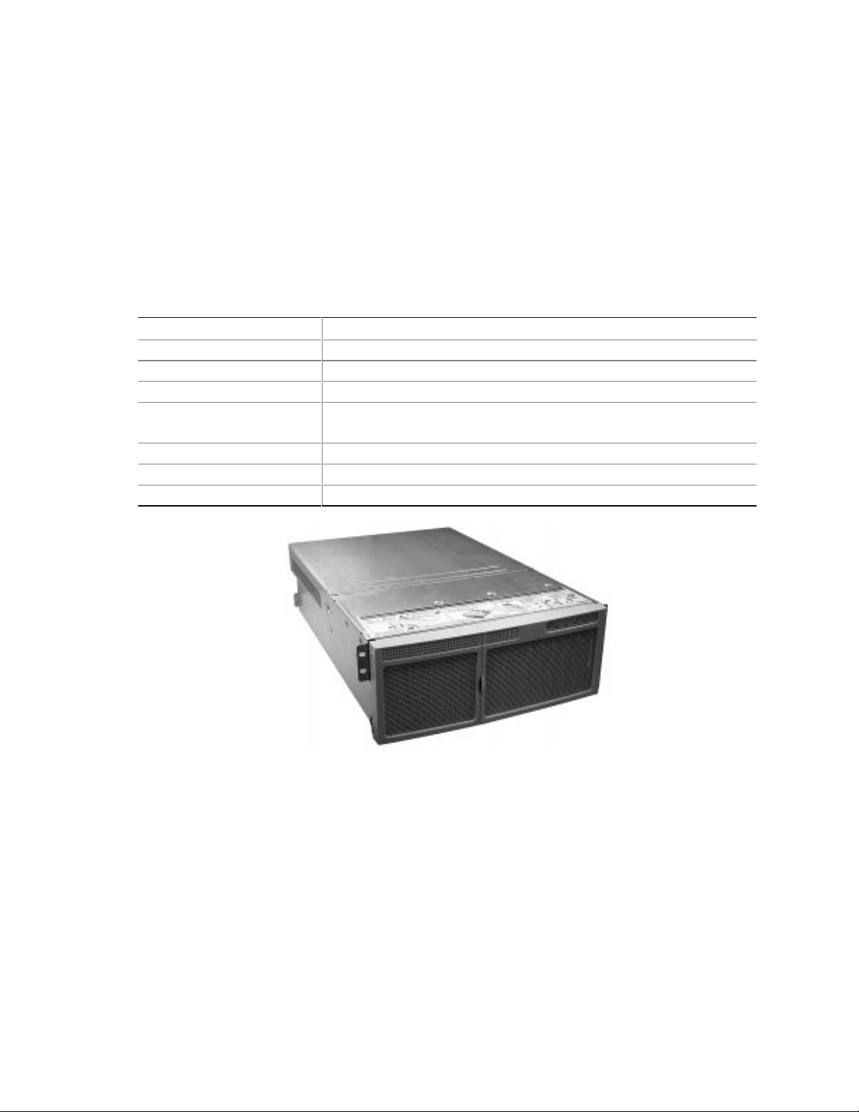
The space requirements for the SRKA4 MP server system are specified in the following table.
Table 1. SRKA4 MP Server Physical Specifications
Specification Rack Mode Only
Height 4u (7 inches)
Width 17.5 inch rack
Depth 26.5 inches
Weight 57 pounds, minimum configuration
88 pounds, maximum configuration
Required front clearance 3 inches (inlet airflow <35 °C / 95 °F)
Required rear clearance 6 inches (no airflow restriction)
Required side clearance 1 inch
8 Quick Start Guide
OM09980
Figure 1. SRKA4 MP Server System
Page 9
General Site Criteria
The server operates reliably within normal office environmental limits. Select a site that meets
these criteria:
• Near a properly earthed, grounded, three-pronged power outlet
In the United States and Canada: a NEMA 6-15R outlet for 100-120 V and for 200-240 V.
In other geographic areas: a properly earthed, grounded outlet in accordance with the local
electrical authorities and electrical code of the region.
• Clean and relatively free of excess dust.
• Well ventilated and away from sources of heat, with the ventilating openings on the server
kept free of obstructions.
• Away from sources of vibration or physical shock.
• Isolated from strong electromagnetic fields and noise caused by electrical devices such as
elevators, copy machines, air conditioners, large fans, large electric motors, radio and TV
transmitters, and high-frequency security devices.
• Access space provided so the server power cords can be unplugged from the power supply or
the wall outlet; this is the only way to remove AC power from the server.
• Clearance provided for cooling and airflow.
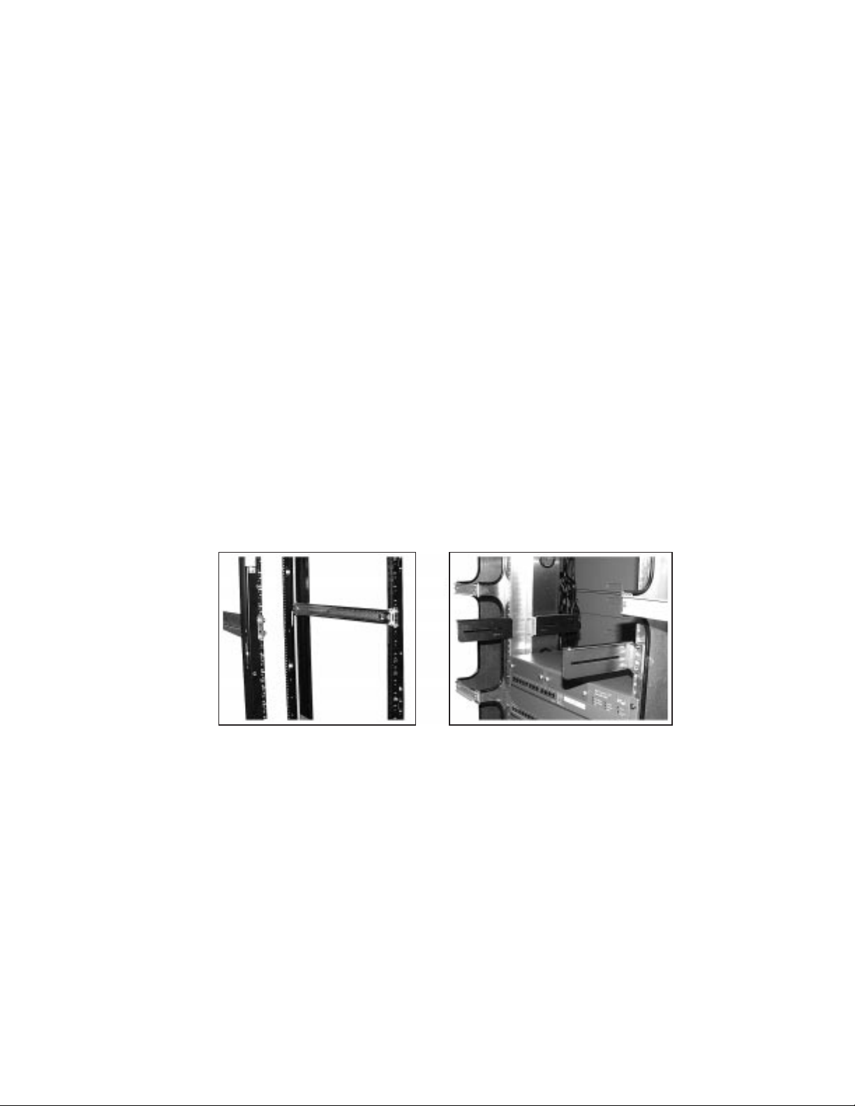
Mounting the SRKA4 Server System in a Rack
The SRKA4 server system is a rack-mounted system, which means that you install it in a rack.
You install the system in either a slide rail or center-mount rack configuration.
OM09981
Figure 2. Slide Rail
Configuration
Figure 2a. Center-mount
Configuration
The slide rail configuration is shown in Figure 2. There are four posts, each with holes spaced at
small intervals. Each slide rail in the slide rail assembly is connected to the front and back of the
rack. If mounting the server in a slide rail configuration, you only need the slide rail kit. Note the
equipment rack precautions below, and follow the instructions in the “Slide Rail Kit” section on
page 11.
The center-mount configuration is shown in Figure 2a. There is a center bar with holes on each
side. Center-mount brackets are attached to the center bar. If mounting the server in a centermount configuration, you only need the center-mount kit. Note the equipment rack precautions
below, and follow the instructions in the “Center-mount Kit” on page 20.
SRKA4 /ISP4400 Server System 9
Page 10

Equipment Rack Precautions
WARNINGS
MAIN AC POWER DISCONNECT: You are responsible for installing an
AC power disconnect for the entire rack unit. This main disconnect
must be readily accessible, and it must be labeled as controlling power
to the entire unit, not just to the server(s).
G
ROUNDING THE RACK INSTALLATION: To avoid the potential for an
electrical shock hazard, you must include a third wire safety grounding
conductor with the rack installation. If a server power cord is plugged
into an AC outlet that is part of the rack, then you must provide proper
grounding for the rack itself. If server power cords are plugged into
wall AC outlets, the safety grounding conductor in each power cord
provides proper grounding only for the server. You must provide
additional, proper grounding for the rack and other devices installed
in it.
CAUTIONS
Temperature: The operating temperature of the server, when installed in
an equipment rack, must not go below 5 °C (41 °F) or rise above 35 °C
(95 °F). Extreme fluctuations in temperature can cause a variety of
problems in your server.
Ventilation: The equipment rack must provide sufficient airflow to the
front of the server to maintain proper cooling. It must also include
ventilation sufficient to exhaust a maximum of 3,000 Btu's per hour for the
server. The rack selected and the ventilation provided must be suitable to
the environment in which the server will be used.
10 Quick Start Guide
Page 11
Slide Rail Kit
WARNING
Avoid injury: To avoid personal injury when unpacking the server, use
only a mechanical assist unit to lift it off the shipping pallet. The
minimum server configuration weighs 26 kg (57 lbs); the maximum
weighs 40 kg (88 lbs).
Do not attempt to lift or move the server by the handles on the power
supplies.
Use only a hand-truck or other mechanical assist unit to move the server
from one location to another.
To mount the SRKA4 MP server system in a slide rail configuration, install the slide rail kit as
directed in this section. The slide rail kit contains slide rail assemblies, EIA brackets, and several
screws, nuts, and bolts.
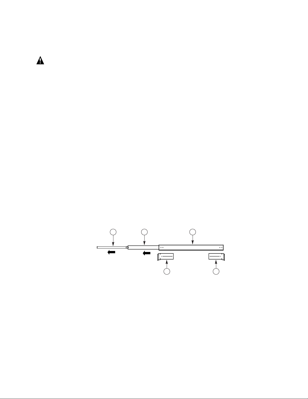
The slide rail kit contains two slide rail assemblies. As shown in Figure 3, the slide rail assembly
contains three moving parts: the inner member, the intermediate member, and the outer member.
The slide rail kit contains four EIA brackets. Two brackets are labeled FL/RR. One is connected
to the front left (FL) of the slide assembly; the other is connected to the rear right (RR). The
remaining two brackets are labeled FR/RL. One is connected to the front right (FR) of the slide
assembly; the other is connected to the rear left (RL). Figure 3 shows where the brackets are
attached to the slide rail assembly.
Screws, lock nuts, and washers are provided for the assembly of each slide rail and attaching the
slide rail to the server. However, you must supply the screws that secure the slide rail to the rack.
A
Figure 3. Slide Assembly Fully Extended
A. Inner member
B. Intermediate member
C. Outer member
D. Front left bracket
E. Rear left bracket
The inner member is the narrowest piece of the slide assembly.
The intermediate member is the middle member of the slide assembly.
The outer member is the widest piece of the slide assembly.
The location of the front left bracket labeled FL/RR.
The location of the rear left bracket labeled FR/RL.
B
D E
C
OM09982
SRKA4 /ISP4400 Server System 11
Page 12

The inner member has a safety latch shown in Figure 4. Without fully extending the slide
assembly, you can move the server in and out from the rack. When the slide assembly is fully
extended, this latch locks the assembly in the fully extended position. When you depress the latch,
you can release the inner member from the rest of the slide assembly.
C
Figure 4. Safety Latch
A. Inner member The inner member is the narrowest piece of the slide assembly.
The inner member is attached to the chassis.
B. Safety latch The safety latch is located on the inner member.
C. Intermediate member The intermediate member slides into the inner member.
B
A
OM09983
WARNING
ANCHOR THE EQUIPMENT RACK: You must anchor the equipment rack
to an unmovable support to prevent it from falling over when the server
is pulled to the front on the slide assembly. The anchors must be able to
withstand a force of up to 113 kg (250 lbs). You must also consider the
weight of any other device installed in the rack.
CAUTION
After completing the rack mount installation, do not depress the safety latch
unless you are removing the chassis from the rack. The purpose of the
safety latch is to prevent the server from unexpectedly sliding out of the
rack.
12 Quick Start Guide
Page 13

Prepare the Slide Assemblies
1. Remove the slide assemblies from the kit.
2. Orient the slide assembly so that the inside of the inner member is facing up and the safety
latch is visible.
3. Fully extend the telescoping slide assembly until the intermediate member hits the safety latch
on the inner member.
4. Depress the safety latch with your thumb. Pull the inner member away from the intermediate
member until the inner member separates from the rest of the slide assembly.
5. Set the intermediate and outer members of the slide assembly aside. You will need them in a
later on.
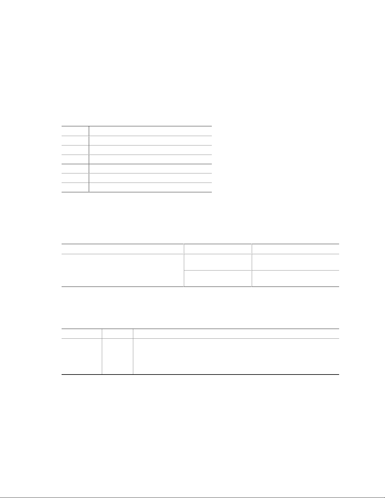
Prepare the Server
1. Remove six #10-32 x 1/4 long pan-head screws from the kit.
2. Orient the first inner member so that the latch points towards the rear of the chassis. The inner
member is noted by "A" in Figure 5. Notice that the safety latch is pointed towards the rear of
the chassis.
A A A
OM09986
Figure 5. Inner Member Attached to Chassis
3. Align the three holes in the inner member with the three holes in the chassis.
4. Insert and tighten a screw through each hole in the bar and chassis wall.
5. Repeat steps 2 through 4 for the other inner member and other side of the chassis.
SRKA4 /ISP4400 Server System 13
Page 14

Attach EIA Rail Brackets
NOTE
✏
Mounting holes in the vertical rails of equipment racks are commonly
spaced in a 5/8 x 5/8 x 1/2-inch sequence. Perform the following steps
carefully; brackets must be mounted with precision to allow room for the
next server you install in a rack.
At this point, you have removed the inner member from the slide assembly. The outer and
intermediate members comprise the slide assembly. Note the location of the brackets in Figure 3
on page 11.
Attach Front Bracket
1. Remove two #8-32 x 1/2 long pan-head screws, two washers, and two lock nuts from the kit.
2. Extend the intermediate member out from outer member so that the hole at the front end of the
outer member is visible through a rectangular hole in the intermediate member. Item B in
Figure 7 on page 15 shows in what direction you must extend the intermediate member.
Item C in Figure 6 shows the extension of the slide rail assembly. On the left side of the slide
assembly, notice that the screw hole in the outer member is in the center of the rectangular
hole in the intermediate member.
A
B
C
OM09987
Figure 6. FL/RR Bracket and Extended Slide Rail Assembly
A. Front left bracket The front left bracket labeled FL/RR.
B. Lower tongue The correct orientation of the lower tongue of the bracket safety latch.
C. Extended slide
assembly
The intermediate member is extended so that the rectangular hole in the
screw hole in the outer member is centered in the rectangular hole of the
intermediate member.
3. Place one of the brackets labeled FL/RR on the outside of the outer member. The lower
tongue of the bracket must be oriented correctly. Item B in Figure 6 shows the bracket’s
correct orientation.
14 Quick Start Guide
Page 15

4. Place a screw in the holes from inside the intermediate member and tighten with a washer and
lock nut. The correct alignment of the screw, washer, lock nut, bracket, and slide assembly is
shown in Figure 7.
D
C
B
E
F
A
OM09984
Figure 7. Correct Alignment of Screw, Washer, Nut, Bracket,
and Slide Assembly at the Front
A. Extended slide rail
assembly
B. Extension direction The intermediate member is extended in this direction.
C. Rectangular hole Screw hole is centered in the rectangular hole of the intermediate member.
D. Front left bracket Front left bracket labeled FL/RR.
E. Screw Screw used to secure the bracket to the slide rail assembly.
F. Washer and lock-nut Correct orientation of the washer and lock-nut.
The slide rail assembly extended so that the screw hole in the outer member
is centered in the rectangular hole of the intermediate member.
CAUTION
Secure the front bracket. Before continuing, make sure that the screw
connecting the front bracket is tightened securely. If it is not, the rack
installation may not be able to support the weight of the server.
5. Slide the intermediate member back and forth over the screw you just tightened. If the
intermediate member cannot slide over the screw, make sure the screw size is correct.
6. Repeat steps 2 through 5 for the other slide assembly.
SRKA4 /ISP4400 Server System 15
Page 16

Attach Rear Bracket
1. Remove four #8-32 x 1/2 long pan-head screws, four washers, and four lock nuts from the kit.
2. Extend the intermediate member out from outer member so that you have complete access to
the rear part of the outer member. Item B in Figure 9 on page 17 shows in what direction you
must extend the intermediate member. Item C in Figure 8 on page 16 shows the extension of
the slide rail assembly. On the right side of the slide assembly, notice that the three screw
holes in the outer member are accessible.
3. Place one of the brackets labeled FR/RL on the outside of the outer member. The lower
tongue of the bracket must be oriented correctly. Item B in Figure 9 on page 17 shows the
correct orientation.
A
B
C
OM09988
Figure 8. FR/RL Bracket and Extended Slide Rail Assembly
A. Rear left bracket The rear left bracket labeled FR/RL.
B. Lower tongue The correct orientation of the lower tongue of the bracket safety latch.
C. Extended slide assembly The intermediate member is extended so that the three screw holes on
the outer member are accessible.
4. Place one of the brackets labeled FR/RL on the outside of the outer member. The lower
tongue of the bracket must be oriented correctly. Item B in Figure 6 on page 14 shows the
bracket’s correct orientation.
5. Align the slot in the bracket with the three holes in the outer member so that all three holes in
the outer member are visible through the slot in the bracket.
16 Quick Start Guide
Page 17

6. Place screws in two of the three holes from inside the intermediate member and loosely tighten
with a washer and lock nut. The correct alignment of the screw, washer, lock nut, bracket, and
slide assembly is shown in Figure 9.
E
C
A
B
D
OMO9985
Figure 9. Correct Alignment of the Screw, Washer, Nut, Bracket,
and Slide Assembly at the Rear
A. Extended slide rail
assembly
B. Extension direction The intermediate member is extended in this direction.
C. Rear left bracket Rear left bracket labeled FR/RL.
D. Screw One of two screws used to secure the bracket to the slide rail assembly.
E. Washer and lock-nut Correct orientation of the washer and lock-nut for each screw.
The slide rail assembly extended so that the screw hole in the outer member
is centered in the rectangular hole of the intermediate member.
Notice what screw holes are used on the outer member.
7. Slide the bracket back and forth. Make sure that the screws are loose enough to allow the
bracket to move freely.
8. Repeat steps 2 through 7 for the other slide assembly.
SRKA4 /ISP4400 Server System 17
Page 18

Attach the Slide Assembly to the Rack
1. Obtain at least four screws from your own inventory.
2. Select the holes you are going to use on the rack.
3. Align the holes on one of the front brackets with the holes you selected on the rack. The holes
are noted by "A" in Figure 10.
A
OM09989
Figure 10. Slide Assembly Aligned with Holes in the Vertical Rack
4. As shown in Figure 10, insert two screws in the front bracket and rack holes. Tighten the
screws to secure the front of the slide assembly to the rack.
5. Adjust the rear bracket so that it meets the rear vertical rail of the rack.
6. Insert two screws in the rear bracket and rack holes. Tighten the screws to secure the rear of
the slide assembly to the rack.
7. Repeat steps 2 through 6 for the other slide assembly.
Place the Chassis in the Rack
Lift the chassis with hand-truck or other mechanical assist unit so that the inner members on the
server line up with the slide assembly attached to the rack. Gently push the chassis into the rack.
Make sure that the inner member slides smoothly into the slide assembly in the rack.
18 Quick Start Guide
Page 19

Install Handles
The handles attach to the chassis. As an option, you can also attach the handles to the rack.
1. Make sure that you pull the chassis out of the rack until the safety latch snaps into place.
2. As shown in Figure 11, align the inside top and bottom handles with the top and bottom holes
of the chassis.
OM09999
Figure 11. Handles Aligned with Chassis
3. Place screws in the top and bottom holes on the inside edge of the handle. Tighten both screws
to secure the handle to the chassis.
4. If you want to secure the handle to the vertical rack, place screws in the top and bottom holes
on the outside edge of the handle. Tighten both screws.
Attach the Front Bezel to the Chassis
The front bezel attaches to and protects the front of the server.
1. Make sure that you pull the chassis out of the rack until the safety latch snaps into place.
2. Place the front bezel over the front of the chassis. The edge of the bezel should line up with
the front edges of the chassis. The ball studs on the back of the bezel fit easily into holes on
the front of the server.
3. Gently push the front bezel into the chassis. The front bezel snaps into place.
Removing the Server from the Rack
1. Pull the server out until the safety latches on each side lock into place.
2. Make sure that a hand-truck or other mechanical assist unit is placed directly under the server.
3. Depress the safety latches on both sides and simultaneously pull the chassis out of the slide
assembly.
4. Pull the hand-truck or other mechanical assist unit out along with the chassis.
SRKA4 /ISP4400 Server System 19
Page 20

Center-mount Kit
WARNING
AVOID INJURY: To avoid personal injury when unpacking the server,
use only a mechanical assist unit to lift it off the shipping pallet. The
minimum server configuration weighs 26 kg (57 lbs); the maximum
weighs 40 kg (88 lbs).
Do not attempt to lift or move the server by the handles on the power
supplies.
Use only a hand-truck or other mechanical assist unit to move the server
from one location to another.
To mount the SRKA4 server system on a center-mount configuration, install the center-mount kit
as directed in this section.
The center-mount kit contains four EIA brackets, and several screws, nuts, and bolts. Screws,
nuts, and bolts are provided for securing the brackets to the chassis. However, you must supply the
screws that secure the brackets to the rack.
There are two sets of EIA rail brackets. One set is labeled FL/RR. These brackets are attached to
the front of the slide assembly. The other set is labeled FR/RL. These brackets are attached to the
back of the slide assembly.
WARNING
ANCHOR THE EQUIPMENT RACK: To prevent the equipment rack from
falling over, you must anchor the equipment rack to an unmovable
support. The anchors must be able to withstand a force of up to 113 kg
(250 lbs). You must also consider the weight of any other device
installed in the rack.
20 Quick Start Guide
Page 21

Attach EIA Rail Brackets to the Rack
1. Separate the brackets labeled FR/RL from the brackets labeled FL/RR.
2. Decide what side of the rack is the "front" side of the rack.
3. Place one of the brackets labeled FR/RL on the front right side of the rack as shown in
Figure 12.
4. Make sure that the holes in the bracket are aligned with the holes in the rack, and that there is
at least 4 inches of clearance below the bottom of the bracket. The two screws are noted by
“A” in Figure 12.
A
OM09991
Figure 12. FR/RL Bracket Attached to Right Side of Rack
5. Secure the bracket to the rack with two screws as shown in Figure 12.
6. Place the other bracket labeled FL/RR on the front left side of the rack.
7. Align the holes in the bracket with the holes in the rack. Make sure that the top of the bracket
is level with the other front right bracket already attached to the rack. The two screws are
noted by “A” in Figure 13.
A
OM09994
Figure 13. FL/RR Bracket Attached to Right Side of Rack
8. Secure the bracket to the rack with two screws as shown in Figure 13.
SRKA4 /ISP4400 Server System 21
Page 22

9. Place one of the brackets labeled FR/RL on the rear left side of the rack as shown in Figure 14.
10. Make sure that the holes in the bracket are aligned with the holes in the rack, and that the top
of the bracket is aligned with the top of the front left bracket already attached to the rack.
A
OM09995
Figure 14. FR/RL Bracket Attached to the Rear Left Side of the Rack
11. The two screws are noted by “A” in Figure 14. Secure the bracket to the rack with two screws.
12. Place the remaining bracket labeled FL/RR on the back left side of the rack.
13. Make sure that the holes in the bracket are aligned with the holes in the rack, and that the top
of the bracket is aligned with the top of the front right bracket already attached to the rack.
14. Secure the bracket to the rack with two screws.
15. Loosen the screws for the brackets so that each one can move left and right freely.
22 Quick Start Guide
Page 23

Secure the Chassis to the EIA Brackets
1. Slide the back of the SRKA4 server system into the rack from the front as shown in Figure 15.
The lip on the chassis is noted by "A" in Figure 15, rests on the brackets.
A
OM09992
Figure 15. Chassis Slides into the Rack
2. Adjust the chassis so that the slot in each bracket lines up with a hole in the chassis. The
chassis should be centered on the rack.
3. Try to make each bracket flush with the chassis. If necessary, slide the brackets left or right.
4. Using the screws provided in the center-mount kit, attach and tighten a screw through the slot
in the bracket and into the chassis.
A
OM09993
Figure 16. Chassis is Secured to Bracket with One Screw Noted by "A"
SRKA4 /ISP4400 Server System 23
Page 24

Attach the Front Bezel to the Chassis
The front bezel attaches to and protects the front of the server.
1. Make sure that you pull the chassis out of the rack until the safety latch snaps into place.
2. Place the front bezel over the front of the chassis. The edge of the bezel should line up with
the front edges of the chassis. The ball studs on the back of the bezel fit easily into holes on
the front of the server.
3. Gently push the front bezel into the chassis. The front bezel snaps into place.
Removing the Server from the Rack
1. Remove the screws securing the chassis to the brackets.
2. Slide the SRKA4 MP server system out of the rack from the front. Make sure that the tabs at
the rear of the server do not get stuck on the front of the front brackets.
Check Power Cord
WARNING
Do not modify or use a supplied AC power cord if it is not the exact type
required in the region where the server will be installed and used.
Replace the cord with the correct type. Refer to the cord requirements
described below.
Do not plug in the server power cord yet if you will be adding internal
parts (boards, DIMMs, removable media drives). For these installation
procedures, see the SKA4 Baseboard Product Guide.
Power Cord Requirements
• Rating: Cords must be rated for available AC voltage and have a current rating at least 125%
of current rating of server.
• Connector, wall outlet end: Cords must be terminated in grounding-type male plug designed
for use in your region. It must have certification marks showing certification by an agency
acceptable in your region.
• Connector, server end: The connector that plugs into the AC receptacle on the server must
be an IEC 320, sheet C13, type female connector.
• Cord length and flexibility: Cords must be less than 4.5 meters (14.76 feet) long, and must
be a flexible (harmonized) cord or VDE-certified cordage to comply with server’s safety
certifications.
NOTES
✏
Surge suppressor recommended: In geographic regions that are
susceptible to electrical storms, we highly recommend that you plug the
server into a surge suppressor.
24 Quick Start Guide
Page 25

EMI information: For information about complying with electromagnetic
interference regulations, see “Electromagnetic Compatibility” in the
SRKA4/ISP4400 Server System Product Guide.
To view or print a Product Guide: See "Product Guides" on page 34.
Connect Monitor, Keyboard, Mouse
CAUTION
Unplug the server. Before connecting external devices, make sure the
server is not plugged in, or equipment could be damaged.
Rear Panel I/O Ports and Features
D
O N
C
OM10264
A
B
M
K
L
J
G
I
H
E
F
Figure 17. Rear Panel I/O Ports and Features
A. AC input power connector
B. Two optional external SCSI connector ports. The figure shows only
one connector port, but your system has two
C. Hot-plug 64-bit, 33 MHz PCI add-in board slots
D. Hot-plug 64-bit, 66/33 MHz PCI add-in board slots
E. Non-hot-plug 32-bit, 33 MHz PCI add-in board slots. These slots can
also accept an optional Intelligent Chassis Management Bus (ICMB)
SEMCONN 6-pin connector in/out connector, port 1
F. Video connector
G. USB ports 0 (upper) and 1 (lower), 4-pin connectors
H. NIC RJ45 connector
I. Serial port 2 (COM2), 9-pin RS-232 connector
J. IEEE 1284 compliant, 25-pin bi-directional parallel connector
K. Serial port 1 (COM1), 9-pin RS-232 connector
L. PS/2-compatible keyboard connector
M. PS/2-compatible mouse connector
N. HW push button
O. PCI green and amber LEDs on the inside of the chassis
SRKA4 /ISP4400 Server System 25
Page 26

Chassis Front Controls and Indicators
B C
D0
D1
A
D2 D3
OM09997
Figure 18. Front Panel Controls and Indicators
A. Power On/Off button: When activated by momentary contact while the system is off, this button turns
the power subsystem on. If the system is in sleep state, activating the button by momentary contact
brings the system out of sleep state. If you press the button down for more than four seconds, you
override ACPI mode and the power is turned off.
B. Reset button: When activated by momentary contact, this button resets the system. If the reset
button is pushed for four seconds or more, the power button is pushed, and then both the reset and
power buttons are released within one second of each other, the CMOS is cleared.
C. Sleep button: When activated by momentary contact, this button puts an operating system supporting
ACPI mode to sleep (S1). When activated by momentary contact during sleep state, the operating
system becomes active. This system does not have a service mode.
D. Front panel LEDs from left to right:
D0 General System Fault LED: Yellow indicates a system failure
D1 NIC activity LED: Green indicates NIC activity
D2 HDD activity LED: Green indicates any system hard drive activity
D3 Main Power LED: Solid green indicates the presence of DC power in the server
Flashing green indicates that the system is in ACPI sleep mode
26 Quick Start Guide
Page 27

Turn on Video Monitor and Server
1. Make sure all external devices, such as a monitor, keyboard, and mouse, have been connected.
2. If present, remove drive protection card from the diskette drive.
3. Turn on the video monitor.
4. Plug the female end of the server AC power cord into the input receptacle on the back of the
chassis.
5. Plug the male end of the server AC power cord into a wall outlet (a grounded, three-pronged
AC power outlet; see page 9 for outlet information).
NOTE
✏
When you plug the AC power cord into a wall outlet, the server may turn on
and boot automatically. In this case, you do not need to turn the push-button
on/off power switch on the front panel.
6. If the server does not come on when you plug it into the AC outlet, press the push-button
on/off power switch on the front panel. See Figure 18 on page 26.
7. Verify that the main power LED on the front panel is lit. After a few seconds, the Power-On
Self Test (POST) begins. See Figure 18 on page 26.
Run Power-On Self Test
Each time you turn on the system, the BIOS begins executing the Power-On Self Test (POST).
POST discovers, configures, and tests the processors, memory, keyboard, and most installed
peripheral devices. The length of time needed to test memory depends on the amount of memory
installed. POST is stored in flash memory.
1. Turn on your video monitor and system. After a few seconds, POST begins to run and a splash
screen is displayed.
2. While the splash screen is displayed, you can either
• Press <F2> to enter the BIOS Setup. See "Changing the BIOS Setup" on page 28.
OR
• Press <Esc> to change the boot device priority for this boot only. See "Changing the Boot
Device Priority Temporarily" on page 30.
3. After pressing <F2> or <Esc> during POST, you can press <Ctrl+A> to run the SCSISelect
Utility. See "Running the SCSISelect Utility" on page 31.
4. If you do not press <F2> or <Esc> and do NOT have a device with an operating system
loaded, the boot process continues and the system beeps once. The following message is
displayed:
Operating System not found
5. At this time, pressing any key causes the system to attempt a reboot. The system searches all
removable devices in the order defined by the boot priority.
6. If you want to boot from a hard drive loaded with an operating system, make sure that the hard
drive is installed and push the Reset button on the front panel.
SRKA4 /ISP4400 Server System 27
Page 28

NOTE
✏
The SRKA4 server system is shipped with the diskette drive set as the first
boot device. Therefore, the server tries to boot from a diskette rather than
from the CD-ROM, regardless of whether there is a CD in the CD-ROM. If
you want to set the CD-ROM as the first boot device for this boot only, press
<Esc>. If you want to permanently set the CD-ROM as the first boot device,
press <F2> to change the boot device priority in the BIOS setup.
7. After POST completes, the system beeps once. If you have an operating system loaded, the
operating system takes control of the server system.
Changing the BIOS Setup
During POST, you can change BIOS settings. These changes are retained until you change the
BIOS settings again.
The instruction set below guides you through the task of changing the boot device priority. This
boot device priority is retained for all future boot processes. After you complete the instructions
below, the server system boots from the CD-ROM drive first. The second and third boot devices
are the diskette drive and hard drive respectively. For more information about changing BIOS
settings, see Chapter 2 in the SKA4 Baseboard Product Guide.
1. Boot the server. The CD can be in the drive or not.
2. Quickly press the <F2> key. A prompt may or may not appear. After a few bootup tests are
completed, the main BIOS Setup screen appears.
3. From the Setup screen, select Boot Menu. Press <Enter>.
4. Select Boot Device Priority, and press <Enter>.
5. In the Boot Device Priority screen, use the up- or down-arrow keys to select "ATAPI
CD-ROM Drive", or the appropriate SCSI CD-ROM drive, then press the <+> key to move it
to the top of the list.
6. Now set the second boot device to Diskette Drive and the third boot device to Hard Drive.
7. Press the <F10> key to save your changes and exit Setup.
8. When the Exit prompt appears, press <Enter> again.
9. The bootup process continues. When finished, an system prompt is displayed.
10. Make sure the CD is in the drive, and boot the server.
28 Quick Start Guide
Page 29

Booting from CD
A
B
A
B
OM09998
Figure 19. 5.25-inch CD-ROM Device (top),
.5-inch Slim-line CD-ROM Drive (bottom)
A. Open/close push-button switch
B. CD tray, CD with label side up
CAUTION, handle CD only by the edges
Handle the CD by its inner and outer edges. Do not touch the side without
the label (the data side).
CAUTION, CD contains only a limited OS
The CD contains a limited OS with enough function to let you boot from the
CD and copy and use the utility and manual files from the CD.
But this limited operating system is NOT intended to be copied onto
diskettes or onto your hard disk as a full-function operating system that
†
supports networking or Windows
must buy the operating system of your choice and install it on the server.
. To run your server and applications, you
SRKA4 /ISP4400 Server System 29
Page 30

NOTE
✏
The server was shipped with the diskette drive set as the first boot device.
The server will, therefore, try to boot from diskette rather than from the
CD-ROM. Even with the CD in the drive, the server might continue to
display “Operating System Not Found”. Follow the steps in “Changing the
Boot Device Priority Temporarily”.
1. Open the CD tray by pressing the open/close button on the front panel of the CD-ROM drive.
The tray will slide out of the drive.
2. Open the CD case. Press down on the center hub of the case to release the CD.
3. Gently grasp the center hole and outer edge of the CD. Remove it from the case, and place it
label-side showing in the CD tray.
4. For .5-inch CD-ROMs, slide the CD tray into the drive. For other CD-ROMs, press the
open/close button or gently push on the CD tray—it automatically slides into the drive.
5. Push the reset switch on the front panel to restart the server.
6. When POST completes, the server boots from the CD, installs a mouse driver, and displays the
CD-ROM menu bar. Use the arrow keys to scroll through the menu bar and to view the tasks
in the pop-up menus.
Changing the Boot Device Priority Temporarily
During POST, you can change the boot device priority for the current boot process. The changes
made during this instruction set are not retained for the next boot process.
1. Boot the server. The CD must be in the drive.
2. At any time during POST, press <Esc>. When POST completes, a pop-up Boot menu appears.
3. Use the arrow keys to highlight the device you want the server system to boot from first. For
example, if you want the server system to boot from the CD-ROM first, you select "CD-ROM
Drive".
NOTE
✏
One of the selections on the pop-up Boot menu is <Enter Setup>.
Selecting this option brings you into the BIOS setup. For more information
about the BIOS setup, see "Changing the BIOS Setup" on page 28.
4. Press <Enter>.
5. The bootup process continues. When finished, a system prompt is displayed.
30 Quick Start Guide
Page 31

Changing the Boot Device Priority Permanently
You can change the boot device permanently. Until you change the boot device priority again via
this instruction set, the boot device priority does not change.
1. Quickly press the <F2> key. A prompt may or may not appear. After a few bootup tests
complete, the main BIOS Setup screen appears.
2. From the Setup screen, select Boot Menu. Press <Enter>.
3. Select Boot Device Priority, and press <Enter>.
4. In the Boot Device Priority screen, use the up- or down-arrow keys to select "ATAPI
CD-ROM Drive", or the appropriate SCSI CD-ROM drive, then press the <+> key to move it
to the top of the list.
5. Now set the second boot device to Diskette Drive and the third boot device to Hard Drive.
6. Press the <F10> key to save your changes and exit Setup.
7. When the Exit prompt appears, press <Enter> again.
8. The bootup process continues. When finished, an OS prompt displays.
9. Make sure the CD is in the drive, and boot the server.
Running the SCSI
Each host adapter includes an onboard SCSISelect configuration utility that allows you to
configure/view the settings of the host adapters and devices in the server.
After pressing <F2> or <Esc> during POST, the splash screen is replaced by text.
The system first finds the Adaptec
"Adaptec AIC-7880 SCSI BIOS V x.xxx" where x.xxx is the version number of the SCSISelect
utility. Pressing <Ctrl+A> at this time allows you to configure the Adaptec AIC-7880 SCSI host
adapter.
If you do not press <Ctrl+A>, the system finds the Adaptec AIC-7899 SCSI host adapter and
displays the message "Adaptec AIC-7899 SCSI BIOS V x.xxx" where x.xxx is the version number
of the SCSISelect utility. Pressing <Ctrl+A> at this time allows you to configure the Adaptec
AIC-7899 SCSI host adapter.
Once you enter the configuration menus for one of the host adapters, you cannot switch to the
other adapter. For example, once you press <Ctrl+A> to configure the Adaptec AIC-7899 SCSI
host adapter, you have to reboot the system to configure the Adaptec AIC-7880 SCSI host adapter.
When to Run the SCSI
Use the SCSISelect utility to
• Change default values
• Check and/or change SCSI device settings that may conflict with those of other devices in the
server
• Do a low-level format on SCSI devices installed in the server
Select
†
AIC-7880 SCSI host adapter and displays the message
Select
Utility
Utility
SRKA4 /ISP4400 Server System 31
Page 32
Running the SCSI
Select
Utility
1. When this message appears on the video monitor:
Press <Ctrl><A> for SCSISelect(TM) Utility!
2. Press <Ctrl+A> to run the utility. When the main menu for the host adapter appears, choose
the adapter that you want to configure—each SCSI bus accepts up to 15 devices.
Use the following keys to navigate through the menus and submenus.
Table 2. Navigation Keys
Press To
ESC Exit the utility
Enter Select an option
↑ Return to a previous option
↓ Move to the next option
F5 Switch between color and monochrome
F6 Reset to host adapter defaults
Configuring the Adaptec AIC-7880 SCSI Adapter
The following menu is displayed when you configure the Adaptec AIC-7880 SCSI adapter.
Table 3. Main Menu
Host Adapter Option Comment
AIC-7880 Ultra/Ultra W at Bus:Device 00:01h Configure/View Host
Adapter Settings
SCSI Disk Utilities Press <Enter> to view the SCSI
Press <Enter> to view the
Configuration Menu.
Disk Utilities Menu.
Make a selection and press <Enter>.
When you are finished, press <Esc> and make your selection from the following menu.
Table 4. Exit Menu
Feature Option Comment
Exit Utility? Yes
No
When you finish configuring your SCSI devices, select Yes and press <Enter>.
When this message appears:
Please press any key to reboot
Press any key, and your server will reboot.
32 Quick Start Guide
Page 33

Configuring the Adaptec AIC-7899 SCSI Adapter
The Adaptec AIC-7899 SCSI adapter has two busses. Select the bus from the following menu.
Table 5. Main Menu
Menu Item Menu Option
You have an AIC-7899 adapter in your system. Move
the cursor to the bus:device:channel of the one to be
configured and press <Enter>.
<F5> - Toggle color/monochrome
After selecting the bus, the following menu is displayed.
Table 6. Menu for each SCSI Channel
Host Adapter Option Comment
AIC-7899 at
Bus:Device:Channel
01:06:A (or 01:06:B)
Configure/View Host
Adapter Settings
SCSI Disk Utilities Press <Enter> to view the SCSI Disk Utilities
When you are finished, press <Esc> and make your selection from the following menu.
Bus:Device:Channel
01:06:A
01:06:B
Press <Enter> to view the Configuration Menu.
Menu. This menu allows you to format hard
disks and/or verify disk media.
Table 7. Exit Menu
Feature Option Comment
Exit Utility? Yes
No
When you finish configuring your SCSI devices, press <Esc>. Then select
Yes and press <Enter>. When this message appears:
Please press any key to reboot
Press any key, and the server reboots.
Country Kit Contents
Server Software Kit
The server software kit includes the server software kit CD. The CD includes
• Product guides
• Device drivers
• SSU and DPC utilities
• Service partition software
• FRU and SDR Load utilities
SRKA4 /ISP4400 Server System 33
Page 34

Product Guides
The server software kit contains two product guides: the SKA4 Baseboard Product Guide and the
SRKA4/ISP4400 Server System Product Guide. The SKA4 Baseboard Product Guide contains
information about the baseboard only and does not include any information specific to the
SRKA4 MP server system. The SRKA4/ISP4400 Server System Product Guide contains
information specific to the SRKA4 MP server system and refers to the SKA4 Baseboard Product
Guide for a detailed description of the baseboard.
For more information about how to read and print these product guides, see "Product Guides" on
page 36.
Device Drivers
The server software kit contains the following drivers.
• SCSI Drivers Adaptec AIC- 7899 SCSI controller
Windows NT† 4.0, Win9X, MS-DOS†, NetWare† 4.X/5.X
NetWare 4.2/5.0
UnixWare† 7.1
Solaris† 7
• SCSI Drivers Adaptec AIC-7880 SCSI controller
Windows NT 4.0, Win9X, DOS
NetWare 4.2/5.0
UnixWare 7.1
UnixWare 2.1
Solaris 7
• Video Drivers ATI Rage2 PCI video
Rage IIc Windows NT 4.0
Rage IIc Windows 95
Solaris 7
UnixWare 7.X
• PCI HP SW Stacks
Windows NT 4.0
Windows 2000
NetWare 4.2/5.0
UnixWare 7.x
• 82559 Network Interface Card (NIC)
Windows NT 4.0
Windows 95
NetWare 4.2/5.0
UnixWare 7.x
Solaris 7
34 Quick Start Guide
Page 35

SSU and DPC Utilities
The server software kit contains many utilities, including System Setup Utility (SSU) and the
Direct Platform Control (DPC) console.
The SSU can be run locally and remotely through a network or modem. The SSU provides a
graphical user interface (GUI) over an extensible framework for server configuration.
The DPC console is run remotely through a modem or direct connection. This interface allows
remote server management.
For more information on both utilities, see the SKA4 Baseboard Product Guide.
Service Partition Software
If purchased, service partition software is included in the server software kit. Software includes
Remote Diagnostics and Service Partition Admin utilities.
FRU and SDR Load Utilities
The Field Replacement Unit (FRU) and Sensor Data Record (SDR) load utility is a DOS-based
program used to update the server management subsystem’s product level FRU, SDR, and the
Desktop Management Interface (DMI) nonvolatile storage components (EEPROMs).
Quick Start Guide
A printed version of this guide is included in the country kit.
Chassis Labels
The country kit contains labels for the chassis. Place these labels on the server system so that the
label's information is easily viewed by anybody accessing server system components.
Hardware
The country kit contains several pieces of hardware and license agreements. They include
• A generic license
• A center-mount and peripheral slide rail assembly
• A power cord
SRKA4 /ISP4400 Server System 35
Page 36

Service Partition (Optional)
When you are setting up your server system, you can install a service partition on your hard drive.
The service partition includes utilities, diagnostics, and other software that a person could run
locally or remotely to assist in system management. The service partition uses approximately
30 to 40 MB of hard disk space.
It is highly recommended that you install the service partition before installing the operating
system. See the Service Partition section in the Installation Guide for the Intel Server Control for
more information. This document is included in the country kit for your system.
Product Guides
Using the Acrobat .PDF Files
Before you can print the SRKA4/ISP4400 Server System Product Guide or the SKA4 Baseboard
Product Guide from Acrobat, you must connect a printer to the parallel port.
1. From the CD-ROM menu bar, select Read/Print Manuals and press <Enter>. The Adobe
Acrobat reader will be automatically installed on RAM disk d: (simulated disk drive in RAM
memory) and automatically started. The reader lets you view and print out a copy of the
product guide.
2. After the reader starts, a pop-up menu displays a list of several manuals. If you are not sure
which manual applies to your server, check the title page of this guide for the correct product
reference.
3. Use your mouse or the up- and down-arrow keys to select the manual. Double click the left
mouse button or press <Enter> to load the .PDF file for the manual.
4. Use your mouse or the tab key to select the .PDF file for the manual. Double click the left
mouse button or press an arrow key and <Enter> to view the .PDF file.
5. Follow the program options and prompts. If you need to access the Help menu, double click
on Help or press <Alt+h>.
Copying Configuration Software to Diskettes
When you copy software from the CD onto diskettes, device drivers suitable for several different
operating systems are copied onto the diskettes. However, your operating system will read only
those drivers it can recognize, so you cannot usually check the directory of a diskette that is not
formatted for your operating system. Instead, you might see a message to the effect, “disk not
formatted, do you want to format it now?” Don’t worry; the drivers for YOUR operating system
are on the diskette and available to load on the system.
1. Before starting, make sure that you have several blank high-density diskettes.
2. From the CD-ROM menu bar, select Create Diskettes and press <Enter>.
3. Follow the prompts to copy the software onto the diskettes.
4. When finished, from the CD-ROM menu bar, select Quit to DOS and press <Enter>.
5. Remove the CD from the CD-ROM drive.
36 Quick Start Guide
 Loading...