

Page 1

SRKA4/ISP4400 Server System Product Guide
Order Number: A07928-003
Page 2

Disclaimer
Intel Corporation (Intel) makes no warranty of any kind with regard to this material, including, but not limited to, the implied
warranties of merchantability and fitness for a particular purpose. Intel assumes no responsibility for any errors that may
appear in this document. Intel makes no commitment to update nor to keep current the information contained in this
document. No part of this document may be copied or reproduced in any form or by any means without prior written
consent of Intel.
®
An Intel
product, when used in accordance with its associated documentation, is "Year 2000 Capable" when, upon
installation, it accurately stores, displays, processes, provides, and/or receives date data from, into, and between the
twentieth and twenty-first centuries, including leap year calculations, provided that all other technology used in combination
with said product properly exchanges date data with it.
†
Third party brands and names are the property of their respective owners.
Copyright © 1999, 2000 Intel Corporation.
Page 3

Contents
Part I: User’s Guide........................................................................................................... 9
1 Chassis Description
Chassis Features ............................................................................................................... 13
Peripherals................................................................................................................ 14
Hard Drives................................................................................................................ 15
Power Subsystem...................................................................................................... 16
System Cooling.......................................................................................................... 17
Chassis Front Controls and Indicators....................................................................... 18
Rear Panel I/O Ports and Features............................................................................ 19
2 Baseboard Description ............................................................................................. 21
3 Configuration Software and Utilities.................................................................... 23
4 Removing and Installing User Serviceable Components
SCSI Hard Drives............................................................................................................... 26
Mounting a SCSI Hard Drive in a Carrier................................................................... 26
Removing a SCSI Hard Drive....................................................................................26
Installing a SCSI Hard Drive...................................................................................... 28
Hot-plug PCI Add-in Boards...............................................................................................29
Removing a Hot-plug PCI Add-in Board..................................................................... 30
Installing a Hot-plug PCI Add-in Board....................................................................... 31
Part II: Service Technician’s Guide ........................................................................... 33
5 A Detailed Description of Chassis Features
Chassis Features ............................................................................................................... 35
Peripherals................................................................................................................ 39
Hard Drives................................................................................................................ 39
Power Subsystem...................................................................................................... 41
System Cooling.......................................................................................................... 43
E-Bay ....................................................................................................................... 45
Chassis Front Controls and Indicators....................................................................... 46
Rear Panel I/O Ports and Features............................................................................ 47
6 Removing and Installing System Components
Tools and Supplies Needed................................................................................................ 49
Safety: Before You Remove the Front and Top Covers..................................................... 49
Front Cover........................................................................................................................ 50
Removing the Front Cover and Front Bezel............................................................... 50
Installing the Front Cover........................................................................................... 51
iii
Page 4

Top Cover .......................................................................................................................... 51
Removing the Top Cover........................................................................................... 51
Installing the Top Cover............................................................................................. 51
Memory Retention Bar ....................................................................................................... 52
Removing the Memory Retention Bar........................................................................ 52
Installing the Memory Retention Bar.......................................................................... 52
SKA4 Baseboard................................................................................................................ 53
Removing the Baseboard..........................................................................................53
Installing the Baseboard............................................................................................ 55
Accessing Baseboard Components.................................................................................... 57
Power Subsystem.............................................................................................................. 58
Removing a Power Supply Module............................................................................ 59
Installing a Power Supply Module.............................................................................. 60
Removing a Power Subsystem Bay........................................................................... 60
Installing a Power Subsystem Bay............................................................................. 61
Cooling System..................................................................................................................62
Removing a Fan Board Assembly.............................................................................. 62
Installing a Fan Board Assembly................................................................................ 63
Replacing the Fan Board........................................................................................... 64
Removing Individual Fans.......................................................................................... 65
Installing Individual Fans............................................................................................ 65
Hard Drive Bay................................................................................................................... 66
Removing the Hard Drive Bay ................................................................................... 66
Installing the Hard Drive Bay ..................................................................................... 67
Peripheral Devices.............................................................................................................68
Removing a Drive from the Configurable Media Bay................................................. 68
Installing a Drive in the Configurable Media Bay........................................................ 68
Replacing a Drive in the Device Bay.......................................................................... 69
Drive Cabling Considerations..................................................................................... 69
7 Solving Problems
Resetting the System......................................................................................................... 71
Initial System Startup ......................................................................................................... 71
Initial System Startup Checklist ................................................................................. 71
Running New Application Software..................................................................................... 72
Application Software Checklist................................................................................... 72
After the System Has Been Running Correctly................................................................... 72
System Checklist....................................................................................................... 72
Specific Problems and Corrective Actions.......................................................................... 73
Power Light Does Not Light....................................................................................... 73
No Beep Codes......................................................................................................... 73
No Characters Appear on Screen.............................................................................. 73
Characters Are Distorted or Incorrect ........................................................................ 74
System Cooling Fans Do Not Rotate Properly........................................................... 74
Diskette Drive Activity Light Does Not Light............................................................... 75
Hard drive Activity Light Does Not Light..................................................................... 75
CD-ROM Drive Activity Light Does Not Light............................................................. 75
Network Problems ..................................................................................................... 76
iv SRKA4/ISP4400 Server System Product Guide
Page 5

PCI Installation Tips................................................................................................... 76
Problems with Application Software........................................................................... 76
Bootable CD-ROM Is Not Detected ........................................................................... 77
Error and Informational Messages...................................................................................... 77
POST Codes and Countdown Codes......................................................................... 77
8 Technical Reference
Cables and InterConnect Descriptions ............................................................................... 79
Internal Cables and Connectors................................................................................. 79
Connectors Accessible to the User............................................................................ 81
Peripheral Adapter Boards and Connectors............................................................... 87
A Equipment Log and Configuration Worksheets
Equipment Log .......................................................................................................... 91
Configuration Worksheet........................................................................................... 92
Current Usage........................................................................................................... 93
B Regulatory and Environmental Specifications
Environmental Specifications.............................................................................................. 95
Product Regulatory Compliance......................................................................................... 95
Product Safety Compliance....................................................................................... 95
Product EMC Compliance.......................................................................................... 95
Product Regulatory Compliance Markings................................................................. 96
Electromagnetic Compatibility Notices................................................................................ 96
USA .......................................................................................................................... 96
FCC Verification Statement ....................................................................................... 97
ICES-003 (Canada)................................................................................................... 97
Europe (CE Declaration of Conformity)...................................................................... 97
Japan EMC Compatibility........................................................................................... 98
BSMI (Taiwan)........................................................................................................... 98
D Warnings
WARNING: English (US)................................................................................................. 100
AVERTISSEMENT : Français.......................................................................................... 102
WARNUNG: Deutsch ...................................................................................................... 104
AVVERTENZE: Italiano................................................................................................... 106
ADVERTENCIAS: Español.............................................................................................. 108
Index.................................................................................................................................... 111
Figures
1. SRKA4 MP Server System........................................................................................ 11
2. One of Two Thumbscrews Securing Top Cover........................................................ 12
3. SRKA4 MP Server System Without Cover and Bezel................................................ 13
3a. Overhead View of System......................................................................................... 13
4. Hard Drive Secured in Drive Carrier.......................................................................... 15
5. Fan Board Assembly with Six Fans........................................................................... 17
6. Front Panel Controls and Indicators .......................................................................... 18
7. Rear Panel I/O Ports and Features............................................................................ 19
Contents v
Page 6

8. Hard Drive Secured in Drive Carrier.......................................................................... 26
9. Front of Chassis with Bezel Door Closed................................................................... 27
9a. Front Right Side of Chassis with Bezel Door Open.................................................... 27
10. Disengaging Drive Carrier from Chassis.................................................................... 28
11. PCI Hot-plug Retention Mechanism........................................................................... 29
12. Rear Retention Latch................................................................................................. 29
13. One of Two Thumbscrews Securing Top Cover........................................................ 30
14. Three Screws Securing Front Cover to Chassis........................................................ 35
15. One of Two Thumbscrews Securing Top Cover........................................................ 36
16. SRKA4 MP Server System Without Covers and Bezel.............................................. 36
16a. Overhead View of System and E-Bay........................................................................ 36
17. Hard Drive Secured in Drive Carrier .......................................................................... 40
18. Power Subsystem...................................................................................................... 41
19. Fan Board Assembly With Six Fans........................................................................... 43
20. Fan LEDs Indicating a Fan’s Status........................................................................... 44
21. Front Panel Controls and Indicators .......................................................................... 46
22. Rear Panel I/O Ports and Features............................................................................ 47
23. Memory Retention Bar............................................................................................... 52
24. Power Supply AC Bracket ......................................................................................... 54
25. Screws Securing the E-Bay to the Chassis................................................................ 55
26. Rear Retention Mechanism....................................................................................... 56
27. Power Subsystem from the Front of the Chassis....................................................... 58
28. Ball Stud From Inside the Front Bezel....................................................................... 59
29. Metal Plate Covering the Power Subsystem Bay....................................................... 61
30. One of Two Screws Securing the Fan Board Assembly............................................. 63
31. Fan Assembly Rotated Away From its Base.............................................................. 64
32. Two Tabs Securing the Hard Drive Bay..................................................................... 66
33. Removing the Hard Drive Bay From the Chassis....................................................... 67
34. 3.5-inch Floppy Drive in the Configurable Media Bay ................................................ 68
Tables
1. SRKA4 Server Physical Specifications...................................................................... 11
2. Chassis Feature Summary........................................................................................ 13
3. LED States for Each Hard Drive................................................................................ 27
4. Chassis Feature Summary........................................................................................ 37
5. Standard BIOS Port-80 Codes................................................................................... 77
6. Recovery BIOS Port-80 Codes.................................................................................. 77
7. SRKA4 Cables and Connectors................................................................................. 79
8. Keyboard and Mouse Connectors ............................................................................. 81
9. Serial Ports................................................................................................................ 81
10. Parallel Port............................................................................................................... 82
11. Video Port..................................................................................................................82
12. USB Connector.......................................................................................................... 83
13. ICMB Connectors...................................................................................................... 83
14. Ethernet Connector ................................................................................................... 84
15. Internal SCA-2 HDD Connector................................................................................. 84
16. External Adaptec Ultra 160/m SCSI........................................................................... 86
vi SRKA4/ISP4400 Server System Product Guide
Page 7

17. CD-ROM Adapter Board 40 Position IDE Connector................................................ 87
18. CD-ROM Adapter Board Power Connector ............................................................... 87
19. Audio Connector ........................................................................................................ 88
20. CD-ROM JAE Connector Pin-out............................................................................... 88
21. 34-Position Floppy Connector Pin-out....................................................................... 89
22. Floppy Adapter Board Power Connector................................................................... 89
23. FFC Cable Pin-out..................................................................................................... 90
24. Environmental Specifications..................................................................................... 95
Contents vii
Page 8

viii SRKA4/ISP4400 Server System Product Guide
Page 9

Part I: User’ s Guide
1 Chassis Description
2 Baseboard Description
3 Configuration Software and Utilities
4 Removing and Installing User Serviceable Components
9
Page 10

10 SRKA4/ISP4400 Server System Product Guide
Page 11
1 Chassis Description
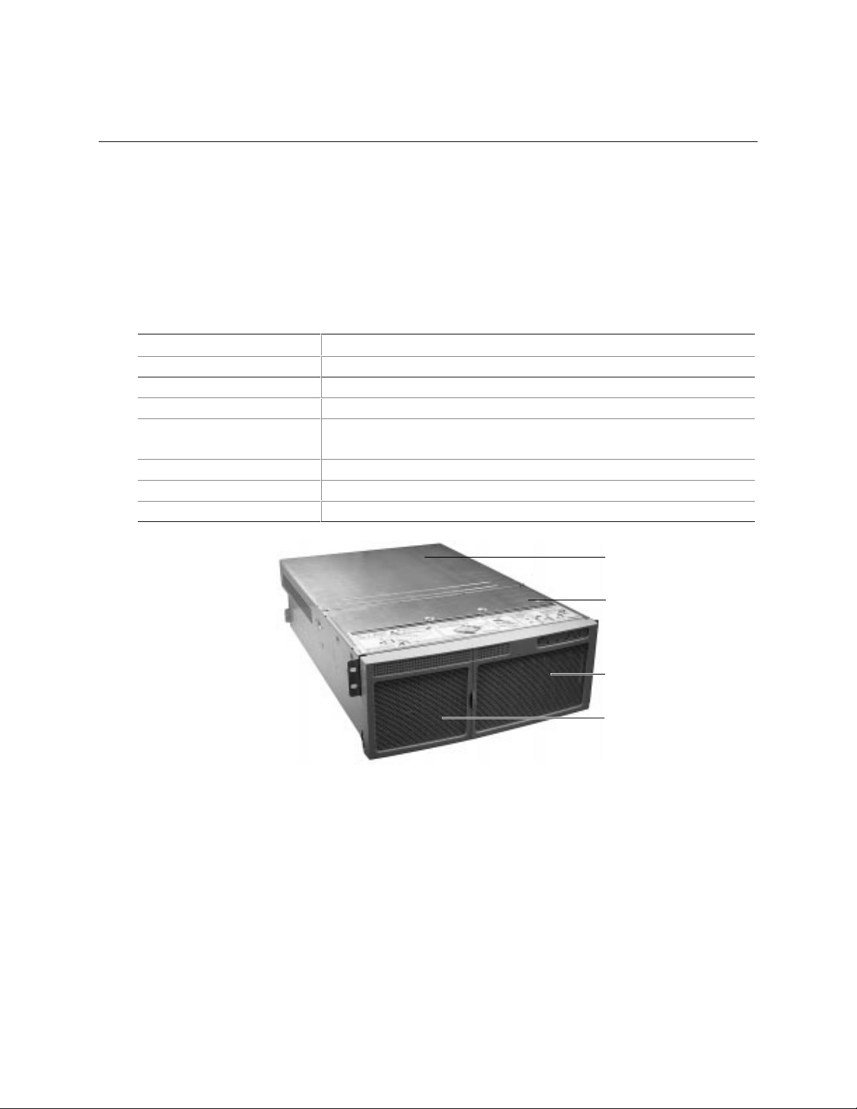
The Intel SRKA4 MP Server System is designed to be mounted in a rack (rack mode). Figure 1
shows an example of this configuration. Before operation, you must purchase an adapter kit and
configure the server so that it can be mounted on a rack.
Contact your customer service representative for details on purchasing a rack adapter kit. For
instructions on mounting the server in a rack, see the SRKA4/ISP4400 Server System Quick Start
Guide accompanying your kit.
Table 1. SRKA4 Server Physical Specifications
Specification Rack Mode Only
Height 4u (7 inches)
Width 17.5-inch rack
Depth 26.5 inches
Weight 57 pounds, minimum configuration
88 pounds, maximum configuration
Required front clearance 3 inches (inlet airflow <35 °C / 95 °F)
Required rear clearance 6 inches (no airflow restriction)
Required side clearance 1 inch
A
B
C
D
OM09934
Figure 1. SRKA4 MP Server System
A. Top Cover. The top cover protects the contents of the chassis.
B. Front Cover. The front cover protects the peripheral devices.
C. Front Bezel Door. When this door is open, you can access hard drives and peripheral devices.
D. Front Bezel.
11
Page 12
The chassis has two covers: a front cover and a top cover. The front cover is secured by screws
and can only be removed by a qualified service technician. The top cover is secured by
thumbscrews and provides user access to hot-pluggable PCI components. One of two
thumbscrews is noted by "A" in Figure 2.
A
OM09935
Figure 2. One of Two Thumbscrews Securing Top Cover
A bezel snaps on to the front of the chassis and allows adequate airflow to cool the system
components. The door in the bezel provides user access to hard drives and the peripheral bay.
12 SRKA4/ISP4400 Server System Product Guide
Page 13
Chassis Features
Figure 3 and Figure 3a give an overhead view of the system with the top cover, front cover, and
front bezel removed.
C
A1
A2
B
Figure 3. SRKA4 MP Server System
E
D
Figure 3a. Overhead View of System
E1
Without Cover and Bezel
Table 2. Chassis Feature Summary
Feature Description
A. Peripheral Bay
[A1 and A2]
A1. Peripheral Bay:
Device Bay
A2. Peripheral Bay:
Configurable
Media Bay
B. Hard Drives The hard drive bay supports either five 1.0-inch or three 1.6-inch hot-swap
C. Power Subsystem Installed:
A peripheral bay in the front of the system has a 5.25-inch device bay and a
configurable media bay.
The device bay can hold a 5.25-inch CD-ROM or DAT device.
Either:
1.44 MB, 3.5-inch diskette drive, accessible from the front after removing the bezel.
Or:
.5-inch slim-line floppy drive and a .5-inch slim-line CD-ROM drive.
Adaptec† Ultra 160/m SCSI hard drives. Hard drives are not installed as part of the
system.
If the operating system supports hot-swapping of hard drives, these drives can be
changed without shutting down the server.
A power subsystem bay that supports up to three 350-watt power supply modules in
a (2+1) redundant configuration.
The power subsystem can o nly be accesse d by qualified service technicians.
E2
OM09936
continued
Chassis Descript ion 13
Page 14
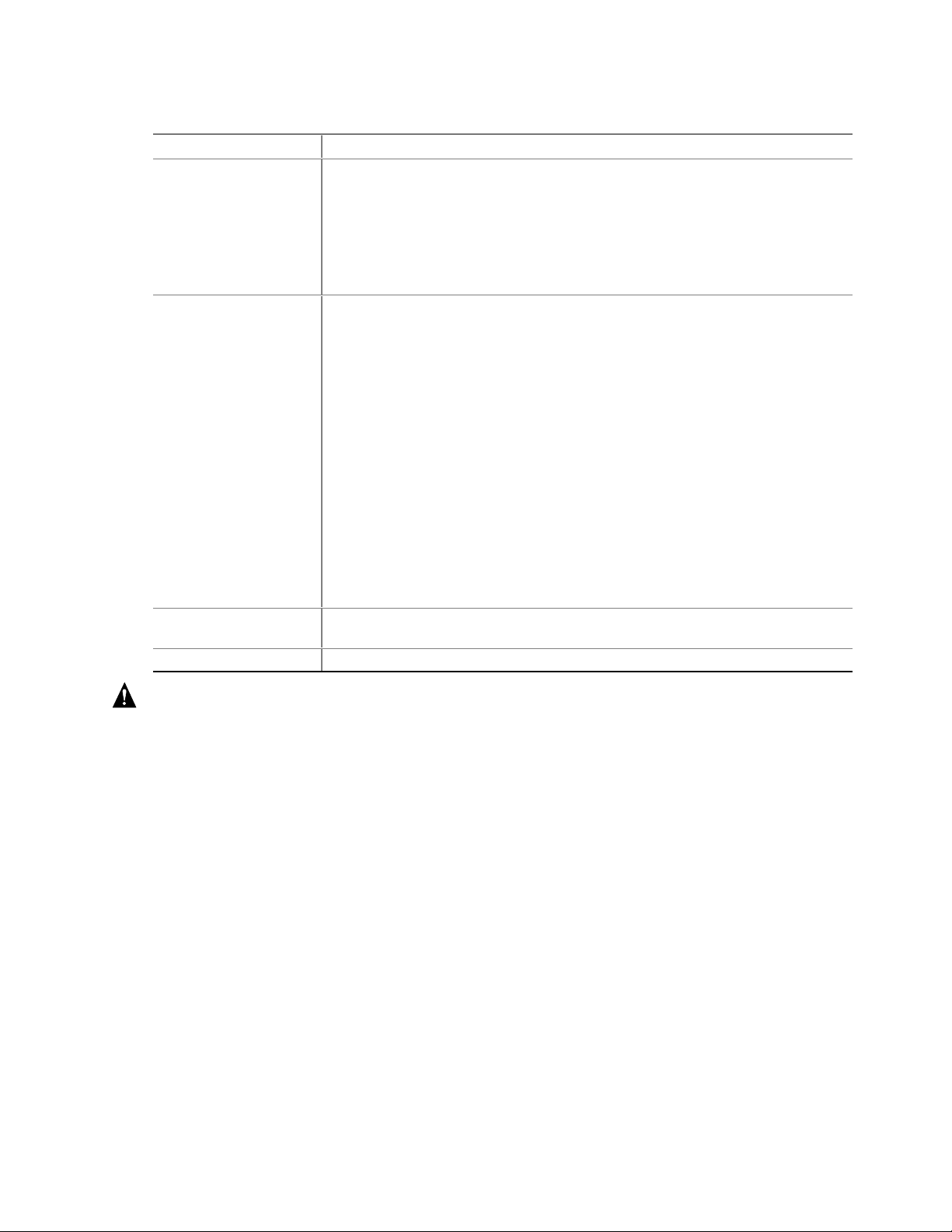
Table 2. Chassis Feature Summary (continued)
Feature Description
D. Cooling Installed:
Fan board assembly and six fans in a redundant (5+1) fan array or three fans in a
non-redundant (3+0) fan array. The fans cool the baseboard and other
components.
In a 5+1 configuration, a failed fan may be removed and installed without shutting
down the server. This process is called hot-swapping. Hot-swapping fans can
only be performed by a qualified service technician.
E. Electronics Bay
(E-Bay)
E1. E-Bay
(Overhead View)
E2. Hot-plug PCI Slots Six hot-plug PCI slots located within the E-Bay.
The E-Bay contains the Intel SKA4 baseboard. The baseboard has the following
major components:
• Up to four Intel
• Server Set III HE chipset
• Up to sixteen PC/100-compliant Registered ECC SDRAM memory modules that
support up to 16 gigabytes of Error Checking and Correcting (ECC)
Synchronous Dynamic RAM
• 32-bit, 33 MHz, 5V PCI slots and three embedded devices
• 64-bit, 66/33 MHz, 3.3V hot-plug PCI slots and one embedded device
• 64-bit, 33 MHz, 5V hot-plug PCI slots and three embedded devices
• ISA bus segment with three embedded devices
• Two externally accessible USB port and one internally accessible USB header
• One IDE connector, supporting up to two ATA33 compatible devices
With the exception of the hot-plug PCI cards, the E-Bay can only be accessed by
qualified service technicians.
An overhead view of the E-Bay.
Pentium III Xeon processors
WARNING
The total power requirement for the SRKA4 MP Server System exceeds
the 240 VA energy hazard limit that defines an operator-accessible area.
Only qualified service technicians should access the processor, memory,
power subsystem, and non hot-plug/hot-swap areas of the SKA4
baseboard.
Peripherals
Peripheral Bay
The chassis contains one peripheral bay for CD-ROM, DAT, and floppy drives. The peripheral
bay contains two smaller bays: a device bay and a configurable media bay.
Device Bay
The device bay accommodates either a 5.25-inch CD-ROM or a DAT drive. Only qualified
service technicians should remove and install components in the device media bay.
14 SRKA4/ISP4400 Server System Product Guide
Page 15
Configurable Media Bay
The configurable media bay supports either one of the following configurations:
• A .5-inch slim line floppy drive and ½-inch slim line CD-ROM drive
• A 3.5-inch floppy drive
Only qualified service technicians should remove and install components in the configurable
media bay.
Hard Drives
The chassis contains up to one hard drive bay. The hard drive bay supports either one of the
following configurations:
• Five 3.5-inch by 1.0-inch hot-swap Adaptec Ultra 160/m SCSI SCA hard drives
• Three 3.5-inch by 1.6-inch hot-swap Adaptec Ultra 160/m SCSI SCA hard drives
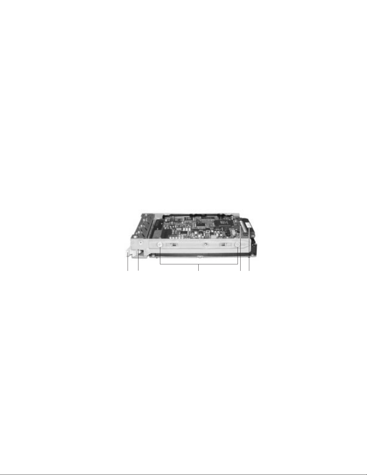
Opening the front bezel door provides user access to the hard drives. As part of the hot-swap
implementation, each hard drive requires a hard drive carrier. When you remove a hard drive from
the system, you remove both the carrier and the hard drive. The drive is attached to the carrier by
four screws. The carrier is locked into the hard drive bay by a locking handle. Figure 4 shows the
orientation of the drive in the carrier. The carrier is upside down in this figure.
E
A
Figure 4. Hard Drive Secured in Drive Carrier
A. Hard drive carrier
B. Two of four fasteners used to attach drive to carrier
C. Hard drive
D. Connector
E. Locking handle
B
C
D
OM09937
Each hard drive is connected to an Adaptec Ultra/m 160 SCSI hot-swap backplane. The backplane
provides industry-standard 80-pin SCA-2 connectors for each hard drive and accepts 10k or slower
drives that consume up to 23 watts of power. If another type or slower Ultra 160 SCSI SCA drive
is installed, make sure that the drive meets these backplane and carrier requirements.
Chassis Descript ion 15
Page 16
✏ NOTE
All hard drives have different cooling, power, and vibration characteristics.
Intel has validated specific hard drive types in the SRKA4 chassis. The
SRKA4 Validation List contains a list of these manufacturers and hard drive
types. The document can be found on
http://support.intel.com/support/motherboards/server/SRKA4/compat.htm
An LED above each hard drive displays the status of that hard drive.
LED State Status
Solid green The hard drive is present and powered on.
Flashing green The hard drive is active.
Solid yellow There is an asserted fault status on the hard drive.
Flashing yellow A rebuild of the hard drive is in progress.
Off The hard drive is not powered on.
Power Subsystem
The SRKA4 MP Server System uses a universal input-switching power subsystem (PSBS). This
subsystem provides up to 630 Watts DC. The subsystem also minimizes the RMS current drawn
from each AC line by providing power factor corrected AC input. The chassis can be configured
with one, two, or three 350-Watt power supply modules, where each is designed to minimize
electromagnetic interference (EMI) and radio frequency interference (RFI).
The power subsystem consists of a power subsystem bay, up to three power supply modules. The
power subsystem bay contains a power distribution board, which manages the power delivered by
all functional power supplies.
The power subsystem can operate in either a nonredundant or redundant way. Operating in a
nonredundant way means that you are using only one or two power supply modules. If the power
supply module ceases to function normally, the server system cannot function properly, if at all. A
minimal configuration supported by one power supply module is one processor, four memory
DIMMs, one hard drive that is not 10K, one floppy drive, and one CD-ROM.
The safer approach is to use a redundant (2+1) power subsystem. To form a (2+1) redundant
power subsystem, the subsystem parallels the DC output of one power supply module with one or
two other modules. If one module ceases to function normally, the remaining modules provide
power to the server system and the system continues to function properly. Two power supply
modules are required to provide power to a fully configured SRKA4 MP Server System. The third
module provides redundancy. A fully configured system includes four processors, eight GB of
memory, one floppy drive, one CD-ROM, five hard drives, and eight PCI add-in boards.
WARNING
The total power requirement for the SRKA4 MP Server System exceeds
the 240 VA energy hazard limit that defines an operator-accessible area.
Only qualified service technicians should access the processor, memory,
power subsystem, and non hot-plug/hot-swap areas of the SKA4
baseboard.
16 SRKA4/ISP4400 Server System Product Guide
Page 17
System Cooling
The SRKA4 MP Server System uses up to six fans mounted in a fan board assembly in the middle
of the chassis between the E-Bay and peripheral device bays. The six fans are noted by "A" in
Figure 5.
A
OM09938
Figure 5. Fan Board Assembly with Six Fans
The SRKA4 server cooling system supports either a non-redundant configuration or a redundant
configuration. A non-redundant configuration includes just three fans. If any one of these three
fans ceases to function normally, environmental conditions within the chassis may exceed the
environmental regulations in this guide and the chassis may not function normally. Three fans
support any system configuration but without fan redundancy.
Operating the server with a non-redundant cooling system is not recommended for systems
requiring high availability. To maintain SRKA4 MP Server System availability, Intel recommends
the use of all six fans to form a redundant cooling system. If one of six fans ceases to function
normally, the remaining five fans adequately cool the system. Using six fans supports any
configuration up to the maximum configuration. Six fans support a maximum set of components.
These components include four processors, 8 GB of SDRAM memory, five 10k hard drives, eight
PCI add-in boards, and at least two power supply modules.
Air flows in through the front bezel over the power subsystem bay, the peripheral bay, and the hard
drive bay. The air then passes through the fan board assembly and to the baseboard. Finally, the
air exhausts through the rear and left side of the chassis.
Individual fan status indicators are located on the fan board mounted in the fan board assembly.
Fan failure is also indicated by the general fault LED located at the front of the chassis.
WARNING
The total power requirement for the SRKA4 MP Server System exceeds
the 240 VA energy hazard limit that defines an operator-accessible area.
Only qualified service technicians should access the processor, memory,
power subsystem, and non hot-plug/hot-swap areas of the SKA4
baseboard.
CAUTION
The top cover must be on the system for proper cooling.
Chassis Descript ion 17
Page 18
Chassis Front Controls and Indicators
B
D0
D1
A
D2 D3
C
OM10262
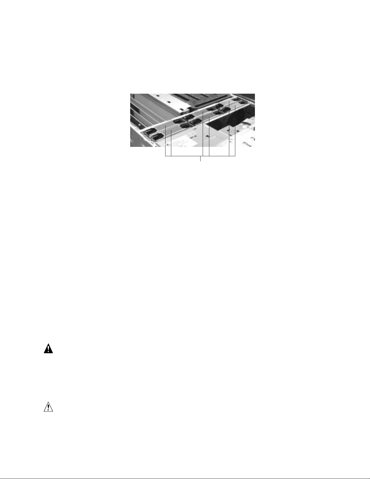
Figure 6. Front Panel Controls and Indicators
A. Power On/Off button: When activated by momentary contact while the system is off, this
button turns the power subsystem on. If the system is in sleep state, activating the button
by momentary contact brings the system out of sleep state. If you press the button down
for more than four seconds, you override ACPI mode and the power is turned off.
B. Reset button: When activated by momentary contact, this button resets the system. If the
reset button is pushed for four seconds or more, the power button is pushed, and then
both the reset and power buttons are released within one second of each other, the
CMOS is cleared.
C. Sleep button: When activated by momentary contact, this button puts an operating
system supporting ACPI mode to sleep (S1). When activated by momentary contact
during sleep state, the operating system becomes active. This syst em does not have a
service mode.
D. Front panel LEDs from left to right:
D0 General System Fault LED: Yellow indicates a system failure.
D1 NIC Activity LED: Green indicates NIC activity.
D2 HDD Activity LED: Green indicates any system hard dri ve activity.
D3 Main Power LED: Solid green indicates the presence of DC power in the server.
Flashing green indicates that the system is in ACPI sleep mode.
18 SRKA4/ISP4400 Server System Product Guide
Page 19
Rear Panel I/O Ports and Features
B
A
O
N
M
K
L
J
G
I
F
E
D
C
H
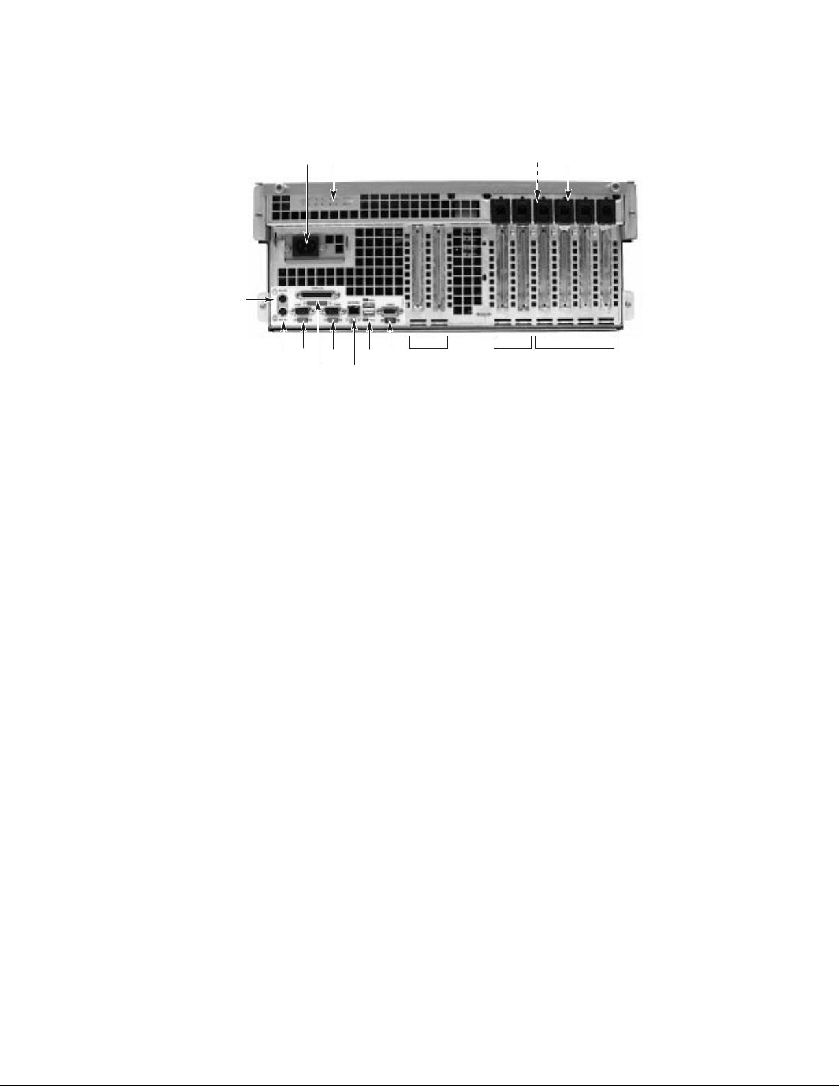
Figure 7. Rear Panel I/O Ports and Features
A. AC input power connector
B. Two optional external SCSI connector ports
The figure shows only one connector port, but your system has two
C. Hot-plug 64-bit, 33 MHz PCI add-in board slots
D. Hot-plug 64-bit, 66/33 MHz PCI add-in board slots
E. Non-hot-plug 32-bit, 33 MHz PCI add-in board slots
These slots can also accept an optional Intelligent Chassis Management
Bus (ICMB) SEMCONN 6-pin connector in/out connector, port 1
F. Video connector
G. USB ports 0 (upper) and 1 (lower), 4-pin connectors
H. NIC RJ45 connector
I. Serial port 2 (COM2), 9-pin RS-232 connector
J. IEEE 1284 compliant, 25-pin bi-directional parallel connector
K. Serial port 1 (COM1), 9-pin RS-232 connector
L. PS/2-compatible keyboard connector
M. PS/2-compatible mouse connector
N. HW push button
O. PCI green and amber LEDs on the inside of the chassis
OM10263
Chassis Descript ion 19
Page 20

20 SRKA4/ISP4400 Server System Product Guide
Page 21

2 Baseboard Description
The SRKA4 MP Server System contains the SKA4 baseboard. For more information about the
SKA4 baseboard, see the SKA4 Baseboard Product Guide contained in your server software kit.
21
Page 22

22 SRKA4/ISP4400 Server System Product Guide
Page 23

3 Configuration Software and Utilities
Configuration software and utilities are part of the SKA4 baseboard. For more information about
configuration software and utilities, see the SKA4 Baseboard Product Guide contained in your
server software kit.
23
Page 24

24 SRKA4/ISP4400 Server System Product Guide
Page 25
4 Removing and Installing User Serviceable
Components
A user can remove and install two components. They are:
• Hot-swappable SCSI hard drives
• Hot-pluggable PCI add-in boards
The term hot-swap describes the process of removing and installing a system component
WITHOUT shutting down the server. The term hot-plug describes the same process for
PCI components only.
When removing and installing the hot-plug and hot-swap components described in this chapter, a
user DOES NOT have to shut down the server.
WARNINGS
Hazardous conditions, power subsystem: Hazardous voltage, current,
and energy levels are present inside the power subsystem. There are no
user-serviceable parts inside it; servicing should be done by technically
qualified personnel.
The total power requirement for the SRKA4 MP Server System exceeds
the 240 VA energy hazard limit that defines an operator-accessible area.
Only qualified service technicians should access the processor, memory,
power subsystem, and non hot-plug/hot-swap areas of the SKA4
baseboard.
CAUTION
Electrostatic discharge (ESD) and ESD protection: ESD can damage
hard drives, add-in boards, and other components. This server can withstand
normal levels of environmental ESD while you are hot-swapping SCSI hard
drives. However, Intel recommends doing all procedures in this manual
only at an ESD-protected workstation. If one is not available, provide some
ESD protection by wearing an antistatic wrist strap attached to chassis
ground of the server—any unpainted metal surface—when handling
components.
25
Page 26

SCSI Hard Drives
The system supports Adaptec Ultra 160/m SCSI SCA type or slower hard drives that are 3.5 inches
wide. Contact a sales representative or dealer for a list of approved SCSI devices.
Mounting a SCSI Hard Drive in a Carrier
1. Remove the 3.5-inch wide hard drive from its wrapper and place it on an antistatic surface.
2. Record the drive model and serial number in your equipment log (page 91).
3. Remove the carrier filler panel and save the screws. You need them later in this procedure.
4. Orient the drive so the connector is near the top and rear of the drive carrier. Figure 8 shows
the orientation of the drive in the carrier. The carrier is upside down in this figure.
5. Using the screws from step 3 or other screws of the correct size and length (not supplied),
attach the carrier to the drive.
E
A
Figure 8. Hard Drive Secured in Drive Carrier
A. Hard drive carrier
B. 2 of the 4 fasteners used to attach drive to carrier
C. Hard drive
D. SCA2 connector
E. Locking handle
B
C
D
OM09937
Removing a SCSI Hard Drive
A bank of five LEDs on the front of the hard drive bays monitors the drive status of each drive in
the hot-docking bay. Each LED corresponds directly to a drive, so that the upper-most LED shows
activity in the upper-most drive. The LEDs and corresponding drives are numbered (left to right)
zero to four. When a yellow LED for a hard drive is on continuously, you are permitted to
hot-swap (replace) a bad drive with a good one. If the operating system installed supports
hot-swapping hard drives, the system DOES NOT need to be powered off.
26 SRKA4/ISP4400 Server System Product Guide
Page 27
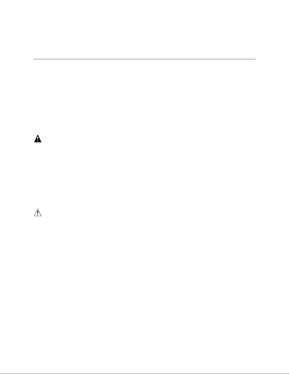
1. Open the front bezel door by simultaneously pulling out on the raised lip of the front bezel
door latch. In Figure 9, the door latch is noted by “A”; the tab used to secure the front bezel
door is noted by “B”.
A
Figure 9. Front of Chassis with
Bezel Door Closed
Figure 9a. Front Right Side of
Chassis with Bezel Door Open
B
OM09941
2. Determine what drive needs to be removed. If necessary, use the LED states below to make
this determination.
Table 3. LED States for Each Hard Drive
LED State Status
Solid green The hard drive is present and powered on.
Flashing green The hard drive is active.
Solid yellow There is an asserted fault status on the hard drive.
Flashing yellow A rebuild of the hard drive is in progress.
Off The hard drive is not powered on.
3. Depress the handle lock with your thumb.
4. Gently pull the locking handle away from the chassis until the handle disengages.
Removing and Installing User Serviceable Components 27
Page 28

5. Grasp the locking handle and pull it toward you to disengage the drive connector from the
backplane connector. The locking handle is noted by "A" in Figure 10.
A
OM09942
Figure 10. Disengaging Drive Carrier from Chassis
6. Carefully slide the drive out of the bay. Place the drive on an antistatic surface.
Installing a SCSI Hard Drive
A bank of five LEDs on the front of the hard drive bays monitors the drive status of each drive in
the hot-docking bay. Each LED corresponds directly to a drive, so that the upper-most LED shows
activity in the upper-most drive. The LEDs and corresponding drives are numbered (left to right)
zero to four. When a yellow LED for a hard drive is on continuously, you are permitted to
hot-swap (replace) a bad drive with a good one. If the operating system installed supports
hot-swapping hard drives, the system DOES NOT need to be powered off.
1. Open the front bezel door by simultaneously pulling out on the raised lip of the front bezel
door latch. See Figure 9 on page 27.
2. Position the new carrier and drive assembly so that it engages the bay guide rails.
3. Gently push the drive into the bay. Swing the locking handle towards the chassis. The locking
handle engages the latch.
4. Close the front bezel door by pressing the door gently into the chassis.
28 SRKA4/ISP4400 Server System Product Guide
Page 29
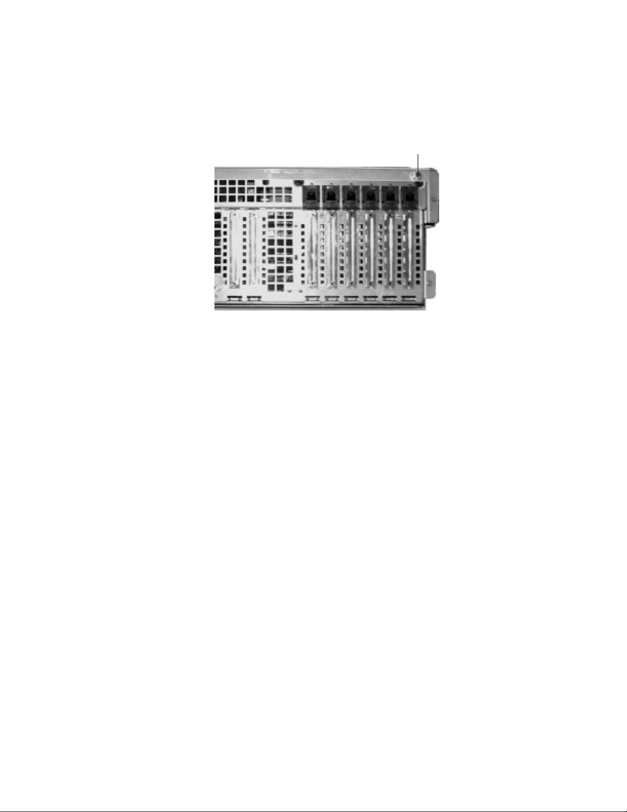
Hot-plug PCI Add-in Boards
The SRKA4 MP Server System supports six hot-plug PCI add-in boards. From the back of the
server system, the six slots are shown in "Rear Panel I/O Ports and Features" on page 19.
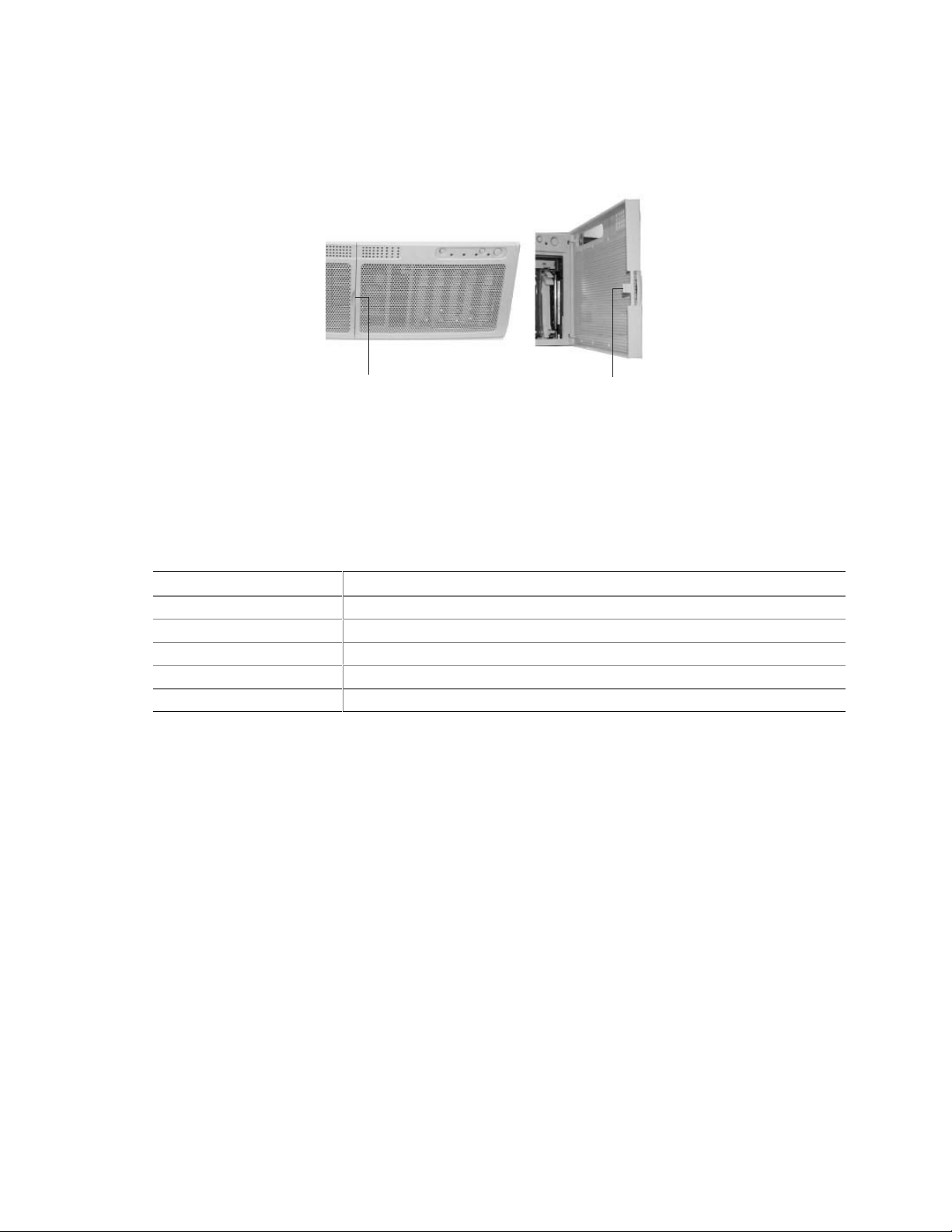
Each hot-plug PCI add-in board is held in place by a PCI Hot-plug (PHP) Retention mechanism.
A
B
C
D
OM09943
Figure 11. PCI Hot-plug Retention Mechanism
A. Green and amber LEDs.
B. Press here on the inside of the chassis and then rotate to release the PCI board.
C. PCI Hot-plug Retention mechanism from the outside of the chassis.
D. HW push-button.
For full-length add-in boards only, the rear of the board is held in place by a rear retention latch.
C
B
A
Figure 12. Rear Retention Latch
A. Hot-plug PCI add-in board.
B. Close up of rear retention latch in the closed position.
C. Rear retention latch in the closed position.
OM09944
Removing and Installing User Serviceable Components 29
Page 30
Removing a Hot-plug PCI Add-in Board
WARNING
If the system has been running, any installed PCI add-in board on the
baseboard will be hot. To avoid the possibility of a burn, be careful
when removing or installing baseboard components that are located
near processors.
CAUTION
Slot covers must be installed on all vacant expansion slots. This
maintains the electromagnetic emissions characteristics of the system and
ensures proper cooling of system components.
1. Observe the safety and ESD precautions at the beginning of this chapter.
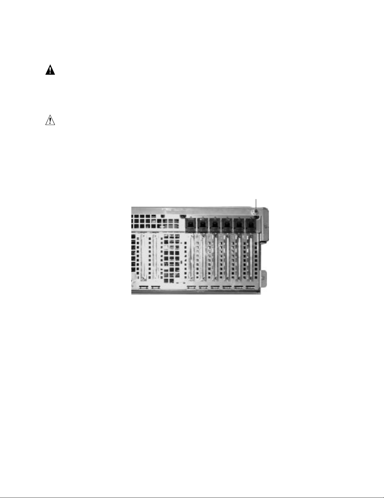
2. Release the two thumbscrews located on the top rear of the chassis. One of two thumbscrews
is noted by "A" in Figure 13.
A
OM09935
Figure 13. One of Two Thumbscrews Securing Top Cover
3. Using an even pull, press lightly on the top cover and slide it back until it stops.
4. Lift the entire top cover upward away from the chassis.
5. Make sure that the slot is powered off. If the slot is powered on, turn the power to the slot off
through the PCI Hot-plug application on your system or through the HW push-button.
6. Disconnect any cables attached to the board you are removing.
7. Press down on the PCI Hot-plug (PHP) Retention mechanism from inside the chassis. Rotate
the mechanism outside the chassis and towards the bottom of the chassis. This action frees the
card’s faceplate. See Figure 11 on page 29.
8. If you are removing a full-length board, release the Rear Retention Latch. See Figure 12 on
page 29.
9. Remove the PCI board by pulling straight up.
10. Store board in an antistatic protective wrapper.
11. If you are not reinstalling a board in the same slot, install a slot cover over the vacant slot. The
tapered foot of the cover must fit into the mating slot in the expansion slot frame.
30 SRKA4/ISP4400 Server System Product Guide
Page 31

12. Before replacing the top cover, check that no left loose tools or parts were left inside the
system.
13. Position the cover over the chassis so that the rows of tabs align with slots in the chassis. Slide
the cover toward the front of the system until the tabs on the cover firmly engage in the
chassis.
14. Attach the top cover to the chassis with the two thumbscrews released earlier, and tighten them
firmly.
15. Connect any external cables.
16. Running the SSU is optional after you remove a PCI add-in board.
Installing a Hot-plug PCI Add-in Board
WARNING
If the system has been running, any installed PCI add-in board on the
baseboard will be hot. To avoid the possibility of a burn, be careful
when removing or installing baseboard components that are located
near processors.
CAUTIONS
Do not overload baseboard: Do not draw too much current from the
baseboard by installing add-in boards that draw excessive current.
ESD and handling boards: Add-in boards can be extremely sensitive to
ESD and always require careful handling. After removing the board from its
protective wrapper or from the baseboard, place it component-side up on a
grounded, static-free surface or conductive foam pad—if available. Do not
slide the board over any surface.
1. Observe the safety and ESD precautions at the beginning of this chapter and this procedure.
2. Release the two thumbscrews located on the top rear of the chassis. One of two thumbscrews
is noted by "A" in Figure 13 on page 30.
3. Using an even pull, press lightly on the top cover and slide it back until it stops.
4. Lift the entire top cover upward away from the chassis.
5. Remove add-in board from its protective wrapper. Be careful not to touch the components or
gold edge connectors. Place board component-side up on an antistatic surface.
6. Record the serial number of the add-in board in your equipment log.
7. Make sure that the slot is powered off. If the slot is powered on, turn the power to the slot off
through the PCI Hot-plug application on your system or through the HW push-button.
8. Set jumpers or switches on the board according to the manufacturer’s instructions.
9. If necessary, remove and save the expansion slot cover.
10. Hold the add-in board by its top edge or upper corners. Firmly press it into an expansion slot
on the baseboard. The tapered foot of the board-retaining bracket must fit into the mating slot
in the expansion slot frame.
11. Press the PCI Hot-plug (PHP) Retention mechanism in towards the back panel. This action
locks the add-in board into place. See Figure 11 on page 29.
Removing and Installing User Serviceable Components 31
Page 32

12. If you are installing a full-length board, lock the Rear Retention Latch. See Figure 12 on
page 29.
13. Use the screw removed earlier to fasten the new board to the chassis. Tighten the screw firmly
(6.0 inch-pounds).
14. Attach cables if necessary.
15. Power on the add-in board through the PCI Hot-plug application on your system or through the
HW push-button.
16. Check that no left loose tools or parts were left inside the system.
17. Position the top cover over the chassis so that the rows of tabs align with slots in the chassis.
Slide the cover toward the front of the system until the tabs on the cover firmly engage in the
chassis.
18. Attach the top cover to the chassis with the two thumbscrews released earlier, and tighten them
firmly.
19. Connect any external cables.
32 SRKA4/ISP4400 Server System Product Guide
Page 33

Part II: Service Technician’s Guide
5 A Detailed Description of Chassis Features
6 Removing and Installing System Components
7 Solving Problems
8 Technical Reference
A Equipment Log and Configuration Worksheets
B Regulatory and Environmental Specifications
C Warnings
33
Page 34

34 SRKA4/ISP4400 Server System Product Guide
Page 35

5 A Detailed Description of Chassis Features
This chapter provides a detailed description of chassis features. For a general description, see
Chapter 1 of this guide.
The SRKA4 MP Server System is designed to be mounted in a rack (rack mode). Before
operation, you must purchase an adapter kit and configure the server so that it can be mounted on a
rack.
Contact your customer service representative for details on purchasing a rack adapter kit. For
instructions on mounting the server in a rack, see the SRKA4/ISP4400 Server System Quick Start
Guide accompanying your kit.
Chassis Features
The chassis has two covers: a front cover and a top cover. The front cover is held in place by three
screws. The screws are noted by "A" in Figure 14.
A
OM09945
Figure 14. Three Screws Securing Front Cover to Chassis
35
Page 36

The top cover is held in place by two thumbscrews, each located at the top rear corner of the
chassis. One of two thumbscrews is noted by "A" in Figure 15.
A
OM09935
Figure 15. One of Two Thumbscrews Securing Top Cover
A bezel snaps on to the front of the chassis and allows adequate airflow to cool the system
components. The door in the bezel provides user access to hard drives and the peripheral bay.
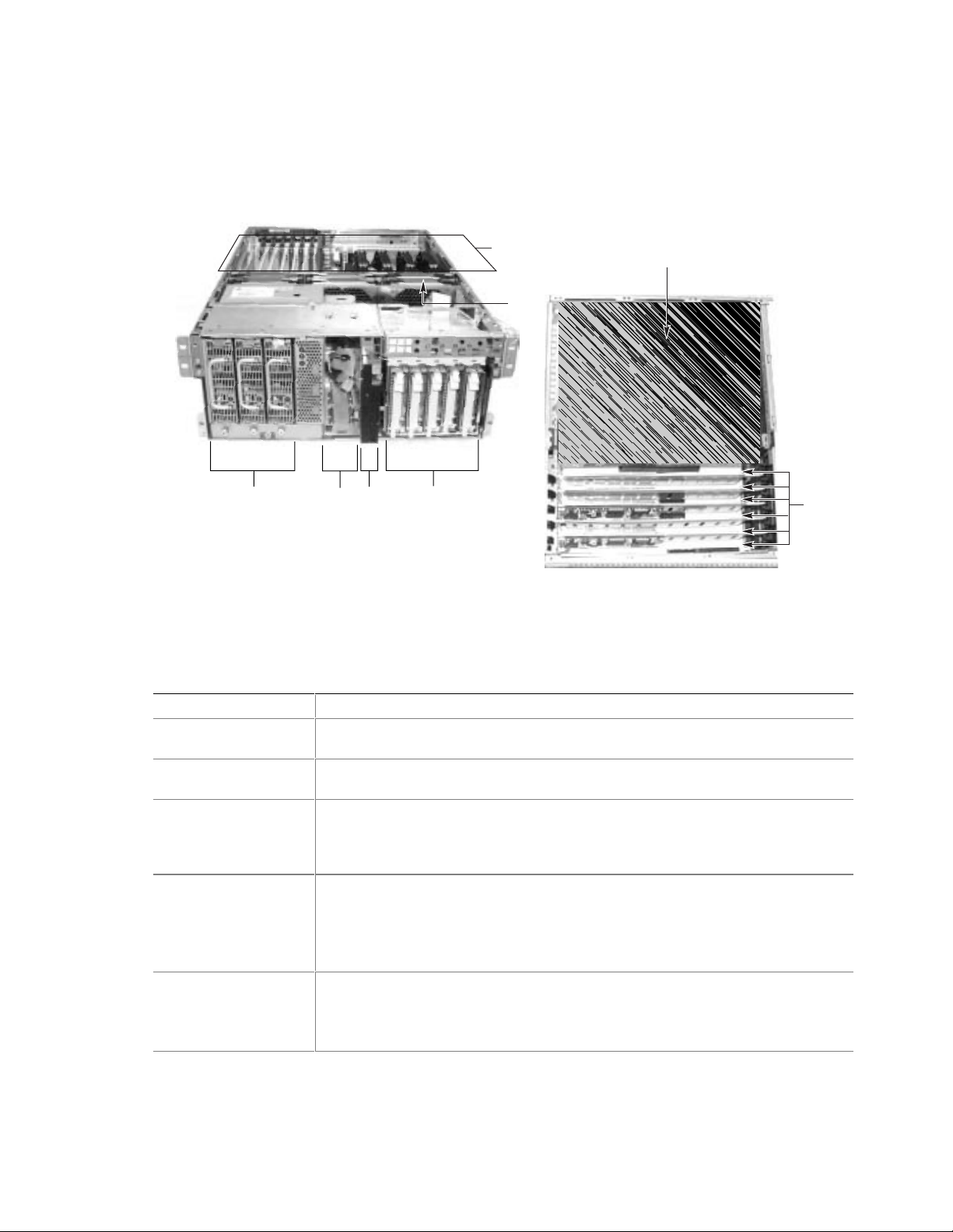
Access to the power supplies is provided by removing the front bezel completely. Figure 16 gives
an overhead view of the system with the top cover and front bezel removed.
C
A1
A2
B
Figure 16. SRKA4 MP Server
System Without Covers and Bezel
E
D
E5
H
E3
E7
I
G
E1
Figure 16a. Overhead View of System
and E-Bay
E6
E2
E4
F
OM09946
36 SRKA4/ISP4400 Server System Product Guide
Page 37

Table 4. Chassis Feature Summary
Feature Description
A. Peripheral Bay A peripheral bay in the front of the system has a 5.25-inch device bay and a
configurable media bay.
A1. Peripheral Bay:
Device Bay
A2. Peripheral Bay:
Configurable
Media Bay
B. Hard Drives The hard drive bay supports either five 1.0-inch or three 1.6-inch hot-swap Adaptec
C. Power Su bsystem Installed:
D. Cooling Installed:
The device bay can hold a 5.25-inch CD-ROM or DAT device.
Either
:
1.44 MB, 3.5-inch diskette drive, accessible from the front after removing the bezel.
Or
:
.5-inch slim-line floppy drive and a .5-inch slim-line CD-ROM drive.
Ultra 160/m SCSI hard drives. Hard drives are not installed as part of the system.
If the operating system supports hot-swapping of hard drives, these drives can be
changed without shutting down the server.
A power subsystem bay that supports up to three 350-watt power supply modules in
a (2+1) redundant configuration.
The power subsystem bay i s mounted at the front-left corner of the chassis and is
shipped with either one or three power supply modules.
A cover plate for any empty power supply location is supplied for a system that does
not have redundancy.
If more than one supply is installed, each power supply can be changed without
shutting down the server.
Fan board assembly and six fans in a redundant (5+1) fan array or three fans in a
non-redundant (3+0) fan array. The fans cool the baseboard and other
components.
In a 5+1 configuration, a failed fan may be removed and installed without shutting
down the server. This process is called hot-swapping. Hot-swapping fans can only
be performed by a qualified service technician.
continued
A Detailed Description of Chassis Features 37
Page 38

Table 4. Chassis Feature Summary (continued)
Feature Description
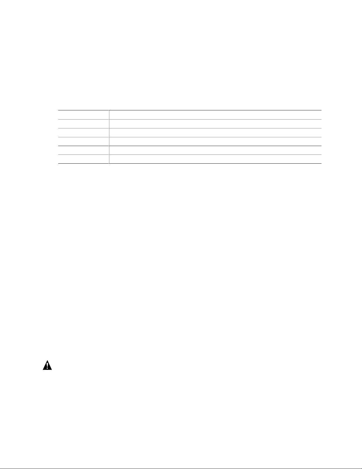
E. Electronics Bay
(E-Bay)
E1. Processors The system supports up to four Intel Pentium III Xeon processors.
E2. Registered
SDRAM Memory
Expansion Slots
E3. PCI Add-In Slots The baseboard contains two 32-bit 33 MHz non-hot-plug PCI slots. These boards
E4. PCI Hot-plug
Slots
E5. SKA4 Baseboard Form-factor, 16 × 13 inches, ATX-style backpanel I/O.
E6. Voltage
Regulator
Module (VRM)
E7. Lithium Battery This battery is used to power the system clock.
F. Front This side is called the front of the E-Bay.
G. Right This side is called the right of the E-Bay.
H. Back This side is called the back of the E-Bay.
I. Left This side is called the left of the E-Bay.
The E-Bay contains the SKA4 baseboard. The baseboard has the following major
components:
• Up to four Intel Pentium III Xeon processors
• Server Set III HE chipset
• Up to sixteen PC/100-compliant Registered ECC SDRAM memory modules that
support up to 16 gigabytes of Error Checking and Correcting (ECC) Synchronous
Dynamic RAM
• 32-bit, 33 MHz, 5V PCI segment with two expansion slots and three embedded
devices
• 64-bit, 66/33 MHz, 3.3V hot-plug PCI segment with two expansion slots and one
embedded device
• 64-bit, 33 MHz, 5V hot-plug PCI segment with four expansion slots and three
embedded devices
• Compatibility bus segment with three embedded devices
• Two externally accessible USB port and one internally accessible USB header
• One IDE connector, supporting up to two ATA33 compatible devices
• One Adaptec AIC-7880 SCSI Controller
• One Adaptec AIC-7899 SCSI Controller
The processors, SDRAM memory modules, and hot-plug PCI components are listed
individually below.
The memory expansion board holds up to sixteen Dual Inline Memory Module
(DIMM) slots and supports up to 8 gigabytes of Error Checking and Correcting (ECC)
Synchronous Dynamic RAM.
are half-length boards only.
The baseboard contains six hot-plug PCI slots. You can add, remove, or exchange a
PCI add-in board from any hot-plug slot without shutting down the server.
The baseboard is mounted horizontally in a subassembly called the E-Bay. The
E-Bay is mounted towards the rear of the chassis.
The baseboard contains connectors for installing up to four Pentium III Xeon
processors in single-edge contact (SEC) cartridges.
The baseboard contains three embedded VRMs and connectors to add three
additional VRMs.
38 SRKA4/ISP4400 Server System Product Guide
Page 39

WARNING
The total power requirement for the SRKA4 MP Server System exceeds
the 240 VA energy hazard limit that defines an operator-accessible area.
Only qualified service technicians should access the processor, memory,
power subsystem, and non hot-plug areas of the SKA4 baseboard.
Peripherals
Peripheral Bay
The chassis contains one peripheral bay for CD-ROM, DAT, and floppy drives. The peripheral
bay contains two smaller bays: a device bay and a configurable media bay.
Device Bay
The device bay accommodates either a 5.25-inch CD-ROM or a DAT drive. Intel strongly
recommends NOT installing any device, such as a hard drive, requiring airflow cooling in the
device bay. Installing such a device in this bay causes environmental conditions to exceed the
cooling and electromagnetic interference (EMI) constraints of the system.
Configurable Media Bay
The configurable media bay supports either one of the following configurations:
• A .5-inch slim line floppy drive and .5-inch slim line CD-ROM drive
• A 3.5-inch floppy drive
Hard Drives
The chassis contains up to one hard drive bay. The hard drive bay supports either one of the
following configurations:
• Five 3.5-inch by 1.0-inch hot-swap Adaptec Ultra 160/m SCSI SCA hard drives
• Three 3.5-inch by 1.6-inch hot-swap Adaptec Ultra 160/m SCSI SCA hard drives
Opening the front bezel door provides user access to the hard drives. As part of the hot-swap
implementation, each hard drive requires a hard drive carrier. When you remove a hard drive from
the system, you remove both the carrier and the hard drive. The drive is attached to the carrier by
four screws. The carrier is locked into the hard drive bay by a locking handle.
A Detailed Description of Chassis Features 39
Page 40

E
A
B
C
D
OM09937
Figure 17. Hard Drive Secured in Drive Carrier
A. Hard drive carrier
B. Four fasteners used to attach drive to carrier
C. Hard drive
D. Connector
E. Locking handle
Each hard drive is connected to an Adaptec Ultra 160/m SCSI hot-swap backplane. The backplane
provides industry-standard 80-pin SCA-2 connectors for each hard drive and accepts 10k or slower
drives that consume up to 23 watts of power. If another type or slower Ultra 160/m SCSI
SCA drive is installed, make sure that the drive meets these backplane and carrier requirements.
✏ NOTE
All hard drives have different cooling, power, and vibration characteristics. Intel has validated
specific hard drive types in the SRKA4 chassis. The SRKA4 Validation List contains a list of these
manufacturers and hard drive types. The document can be found on
http://support.intel.com/support/motherboards/server/SRKA4/compat.htm
An LED above each hard drive displays the status of that hard drive.
LED State Status
Solid green The hard drive is present and powered on.
Flashing green The hard drive is active.
Solid yellow There is an asserted fault status on the hard drive.
Flashing yellow A rebuild of the hard drive is in progress.
Off The hard drive is not powered on.
The SCSI backplane boardset consists of two separate boards: the SCSI backplane board and the
SCSI-Accessed Fault-Tolerant Enclosures Specification (SAF-TE) board. The SCSI backplane
board provides power distribution and SCSI interfacing of the hard drives. The SAF-TE board
provides SAF-TE features and hard drive failure indicators.
40 SRKA4/ISP4400 Server System Product Guide
Page 41

Power Subsystem
The SRKA4 MP Server System uses a universal input-switching power subsystem (PSBS). This
subsystem provides up to 630 Watts DC. The subsystem also minimizes the RMS current drawn
from each AC line by providing power factor corrected AC input. The chassis can be configured
with one, two, or three 350-Watt power supply modules. Each module is designed to minimize
electromagnetic interference (EMI) and radio frequency interference (RFI).
A
OM09947
Figure 18. Power Subsystem
The power subsystem consists of a power subsystem bay and up to three power supply modules.
The power supply modules are noted by "A" in Figure 18. The power subsystem bay contains a
power distribution board, which manages the power delivered by all functional power supplies.
The power subsystem can operate in either a nonredundant or redundant way. Operating in a
nonredundant way means that you are using only one or two power supply modules. If the module
ceases to function normally, the server system cannot function properly, if at all. A minimal
configuration supported by one module is one processor, four memory DIMMs, one hard drive that
is not 10K, one floppy drive, and one CD-ROM.
The safer approach is to use a redundant (2+1) power subsystem. To form a (2+1) redundant
power subsystem, the subsystem parallels the DC output of one power supply module with one or
two other modules. If one module ceases to function normally, the remaining modules provide
power to the server system and the system continues to function properly. Two power supply
modules are required to provide power to a fully configured SRKA4 MP Server System. The third
module provides redundancy. A fully configured system includes four processors, sixteen
gigabytes of memory, one floppy drive, one CD-ROM, five hard drives, and eight PCI add-in
boards.
The SKA4 baseboard contains three embedded voltage converters: two 5 V input and one
12 V input. The baseboard also provides three connectors supporting 8.3-compliant, plug-in
voltage regulator modules (VRM).
A Detailed Description of Chassis Features 41
Page 42

Each power subsystem auto-senses within the following voltage ranges and is rated as follows:
• 100-120 V∼ at 50/60 Hertz (Hz); 11.0 A maximum
• 200-240 V∼ at 50/60 Hz; 5.5 A maximum
The DC output voltages of each power supply module are:
• +3.3 V at 28 A max (Total combined power of the +3.3 and +5 channels must not exceed
195W)
• +5 V at 32 A max (Total combined power of the +3.3 and +5 channels must not exceed 195W)
• +12 V at 12.0 A with 15.0 A peak
• -12 V at 0.5 A
• +5 V standby at 2 A whenever AC power is supplied to the server system
The DC output voltages of the power subsystem with two or three modules are:
• +3.3 V at 50 A max (Total combined power of the +3.3 and +5 channels must not exceed
351W)
• +5 V at 58 A max (Total combined power of the +3.3 and +5 channels must not exceed 351W)
• +12 V at 22.0 A with 28.0 A peak
• -12 V at 0.5 A
• +5 V standby at 2 A
DC power is sourced through a 20-pin and 24-pin power cables to the baseboard. Remote sensing
signals are provided through one 14-pin auxiliary power cable to the baseboard.
The AC power status of each power supply module is indicated by an LED. The LED is located on
the power supply module.
LED State Status
Solid green AC power is applied to the pow er subsystem and standby voltage is available.
Off The LED is off when one of the following conditions occur:
• The power supply modules are disabled by the DC enable signal.
• The power supply module is disabled by another switch.
• The power supply module has been overstressed.
• The power supply module has failed and replacement of the unit is necessary.
There are also three standby channels and each has an LED called a standby LED. These LEDs
are located on the right side of the power subsystem bay and each indicates the status of that
standby channel.
In a redundant configuration, individual power supply modules are hot-swappable. In other words,
you can remove and install a power supply module without shutting down the server. After a
power supply module has been removed from the system, airflow patterns are disrupted within the
system. To maintain correct airflow patterns within the chassis and to ensure that all components
remain within specification under all system environmental conditions, it is recommended that
power supply module hot-swap operations do not exceed two minutes in duration.
42 SRKA4/ISP4400 Server System Product Guide
Page 43

WARNING
The total power requirement for the SRKA4 MP Server System exceeds
the 240 VA energy hazard limit that defines an operator-accessible area.
Only qualified service technicians should access the processor, memory,
power subsystem, and non hot-plug areas of the SKA4 baseboard.
System Cooling
The SRKA4 MP Server System uses up to six fans mounted in a fan board assembly in the middle
of the chassis between the E-Bay and peripheral bays. The six fans are noted by "A" in Figure 19.
A
OM09938
Figure 19. Fan Board Assembly With Six Fans
The SRKA4 server cooling system supports either a non-redundant configuration or a redundant
configuration. A non-redundant configuration includes just three fans. If any one of these three
fans ceases to function normally, environmental conditions within the chassis may exceed the
environmental regulations in this guide and the chassis may not function normally. Three fans
support any system configuration but without fan redundancy.
Operating the server with a non-redundant cooling system is not recommended for systems
requiring high availability. To maintain SRKA4 MP Server System availability, Intel recommends
the use of all six fans to form a redundant cooling system. If one of six fans ceases to function
normally, the remaining five fans adequately cool the system. Using six fans supports any
configuration up to the maximum configuration. Six fans support a maximum set of components.
These components include four processors, 8 GB of SDRAM memory, five 10k hard drives, eight
PCI add-in boards, and at least two power supply modules.
Air flows in through the front bezel over the power subsystem bay, the peripheral bay, and the hard
drive bay. The air then passes through the fan board assembly and the E-Bay. Finally, the air
exhausts through the rear and left side of the chassis.
Individual fan status indicators are located on the fan board mounted in the fan board assembly.
Fan failure is also indicated by the general fault LED located at the front of the chassis.
A Detailed Description of Chassis Features 43
Page 44

An LED above each cooling fan displays the status of that fan. The LEDs for two fans are noted
by "A" in Figure 20. The LED on the left indicates the status of the fan pointed to by the left
arrow. The LED on the right indicates the status of the fan pointed to by the right arrow.
A
Figure 20. Fan LEDs Indicating a Fan’s Status
LED State Status
Solid amber There is a fault with the cooling fan or the cooling fan is not present.
Off The cooling fan is functioning properly.
OM09948
Individual fans are hot-swappable. In other words, you can remove and install a fan without
shutting down the server. After a fan has been removed from the system, airflow patterns are
disrupted within the system. The Baseboard Management Controller (BMC) firmware on the
SKA4 baseboard polls the fans for status once every two minutes. Therefore, the BMC does NOT
detect the removal and installation of an individual fan 3 seconds and two minutes. To maintain
correct airflow patterns within the chassis and to ensure that all components remain within
specification under all system environmental conditions, it is recommended that fan hot-swap
operations do not exceed two minutes in duration.
CAUTION
The top cover must be on the system for proper cooling.
44 SRKA4/ISP4400 Server System Product Guide
Page 45

E-Bay
The E-Bay contains the SKA4 baseboard with the following components:
• Up to four Intel Pentium III Xeon processors. The SKA4 baseboard has four
SC330.1 connectors; each supports a processor. There are also four embedded Voltage
Regulator Modules (VRM) and three VRM 8.3-compliant connectors to support up to four
processors.
• The Server Set III HE chipset. This includes the HE North Bridge, Open South Bridge
(OSB4), and I/O.
• Up to sixteen PC/100-compliant Registered ECC SDRAM memory modules that support up to
16 gigabytes of Error Checking and Correcting (ECC) Synchronous Dynamic RAM.
• 32-bit, 33 MHz, 5V PCI segment with two expansion slots and three embedded devices.
• 64-bit, 66/33 MHz, 3.3V Hot-plug PCI segment with two expansion slots and one embedded
device.
• 64-bit, 33 MHz, 5V Hot-plug PCI segment with four expansion slots and three embedded
devices.
• Compatibility bus segment with three embedded devices.
• Two externally accessible and one internally accessible USB ports.
• One Adaptec AIC-7880 SCSI controller.
• One Adaptec AIC-7899 SCSI controller.
The Adaptec AIC-7899 SCSI controller has two channels called A and B. Channel A is connected
to the HDD Backplane. Channel B is not connected to any device, but could be directed to the
back of the system to an external SCSI device.
The Adaptec AIC-7880 SCSI controller supports both a Legacy Wide SCSI device and Legacy
Narrow SCSI device. Both connections are not a standard part of the SRKA4 MP Server System.
For a Legacy Wide or Narrow device, Intel provides two cables that can be routed to the peripheral
bay on the front of the system. To purchase the cable, contact a sales representative. The Legacy
Narrow connector can be routed to the peripheral bay.
The SRKA4 MP Server System supports up to sixteen memory modules totaling up to
15 gigabytes. However, only memory modules from a specific list of manufacturers are permitted.
The SKA4 Memory Qualification List contains a list of these manufacturers and memory modules
and can be found on
http://support.intel.com/support/motherboards/server/SKA4/compat.htm
For more information on SKA4 baseboard components, see the SKA4 Baseboard Product Guide
contained in your server software kit.
A Detailed Description of Chassis Features 45
Page 46

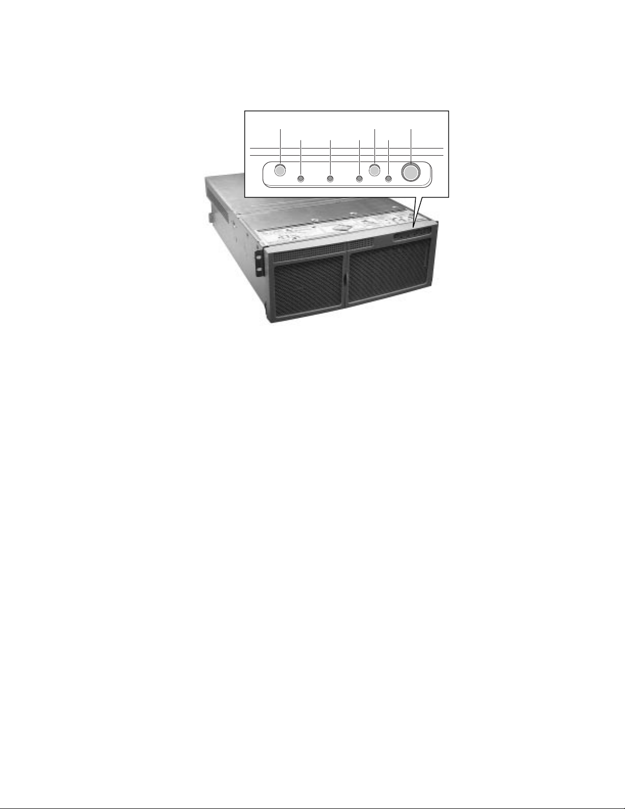
Chassis Front Controls and Indicators
B
D0
D1
A
D2 D3
C
OM10262
Figure 21. Front Panel Controls and Indicators
A. Power On/Off button: When activated by momentary contact while the system is off, this
button turns the power subsystem on. If the system is in sleep state, activating the button
by momentary contact brings the system out of sleep state. If you press the button down
for more than four seconds, you override ACPI mode and the power is turned off.
B. Reset button: When activated by momentary contact, this button resets the system. If the
reset button is pushed for four seconds or more, the power button is pushed, and then
both the reset and power buttons are released within one second of each other, the
CMOS is cleared.
C. Sleep button: When activated by momentary contact, this button puts an operating
system supporting ACPI mode to sleep (S1). When activated by momentary contact
during sleep state, the operating system becomes active. This syst em does not have a
service mode.
D. Front panel LEDs from left to right:
D0 General System Fault LED: Yellow indicates a system failure.
D1 NIC activity LED: Green indicates NIC activity.
D2 HDD activity LED: Green indicates any system hard drive activity.
D3 Main Power LED: Solid green indicates the presence of DC power in the server.
Flashing green indicates that the system is in ACPI sleep mode.
46 SRKA4/ISP4400 Server System Product Guide
Page 47

Rear Panel I/O Ports and Features
B
A
O
N
M
K
L
J
G
I
F
E
D
C
H
Figure 22. Rear Panel I/O Ports and Features
A. AC input power connector
B. Two optional external SCSI connector ports
The figure shows only one connector port, but your system has two
C. Hot-plug 64-bit, 33 MHz PCI add-in board slots
D. Hot-plug 64-bit, 66/33 MHz PCI add-in board slots
E. Non-hot-plug 32-bit, 33 MHz PCI add-in board slots
These slots can also accept an optional Intelligent Chassis Management
Bus (ICMB) SEMCONN 6-pin connector in/out connector, port 1
F. Video connector
G. USB ports 0 (upper) and 1 (lower), 4-pin connectors
H. NIC RJ45 connector
I. Serial port 2 (COM2), 9-pin RS-232 connector
J. IEEE 1284 compliant, 25-pin bi-directional parallel connector
K. Serial port 1 (COM1), 9-pin RS-232 connector
L. PS/2-compatible keyboard connector
M. PS/2-compatible mouse connector
N. HW push button
O. PCI green and amber LEDs on the inside of the chassis
OM10263
A Detailed Description of Chassis Features 47
Page 48

48 SRKA4/ISP4400 Server System Product Guide
Page 49

6 Removing and Installing System Components
Tools and Supplies Needed
• Phillips screwdriver (#1 and #2)
• Flat head screwdriver (#2)
• Jumper-removal tool or needle-nosed pliers
• Antistatic wrist strap and conductive foam pad (recommended)
• Pen or pencil
• Equipment log: As new parts are integrated into the system, add information about them to the
equipment log (page 91). Record the model and serial number of the system, all installed
options, and any other pertinent information specific to the system. Some of this information
may be required when running the SSU.
Safety: Before You Remove the Front and Top Covers
These warnings and cautions apply whenever you remove the top and front covers of the system.
Only a technically qualified person should integrate and configure the system.
WARNINGS
Hazardous conditions, power subsystem: Hazardous voltage, current,
and energy levels are present inside the power subsystem. There are no
user-serviceable parts inside it; servicing should be done by technically
qualified personnel.
The total power requirement for the SRKA4 MP Server System exceeds
the 240 VA energy hazard limit that defines an operator-accessible area.
Only qualified service technicians should access the processor, memory,
power subsystem, and non hot-plug areas of the SKA4 baseboard.
CAUTIONS
Electrostatic discharge (ESD) and ESD protection: ESD can damage
disk drives, boards, and other parts. Intel recommends that all procedures in
this chapter are performed only at an ESD-protected workstation. If one is
not available, provide some ESD protection by wearing an antistatic wrist
strap attached to chassis groundany unpainted metal surfaceon your
system when handling parts.
49
Page 50

ESD and handling boards: Always handle boards carefully. They can be
extremely sensitive to ESD. Hold boards only by their edges. After
removing a board from its protective wrapper or from the system, place it
component-side UP on a grounded, static-free surface. If you place the
baseboard on a conductive surface, the battery leads may short out. If they
do, this will result in a loss of CMOS data and will drain the battery. Use a
conductive foam pad if available but NOT the board wrapper. Do not slide
board over any surface.
Cooling and air flow: For proper cooling and airflow, always install the
front cover before turning on the system. Operating the system without the
top and front covers in place for an extended period of time can damage
system parts.
Removal of the top cover for an extended period of time: If the SRKA4
MP Server System is turned on and has only three fans installed, make sure
that you install the top cover within five minutes of removing it.
Front Cover
Removing the Front Cover and Front Bezel
To reach components inside the system, remove the front cover, and in some cases the front bezel.
Facing the front of the system, the front cover is on top and towards the front of the rack-mounted
chassis. The following tasks require removal of the front cover:
• Removing and installing non-hot-swap drives in the configurable media bay
• Removing and installing media devices in the device bay
• Removing and installing the fan board assembly
• Removing and installing the power subsystem bay
• Removing and installing a power supply module (front bezel only)
To remove the front cover, perform the following steps.
1. Observe the safety and ESD precautions at the beginning of this chapter.
2. Remove the front bezel by gently pulling it towards you. The ball studs will release from the
chassis.
3. Remove the three screws located on the top of the chassis. These screws are noted by "A" in
Figure 14 on page 35. Save these screws; you need them later to reattach the cover.
4. Using an even pull and pressing down, slide the cover back towards the front of the chassis
about .75 inches.
5. Lift the front cover up and out of the chassis.
50 SRKA4/ISP4400 Server System Product Guide
Page 51

Installing the Front Cover
1. Observe the safety and ESD precautions at the beginning of this chapter.
2. Before replacing the front cover, check that no left loose tools or parts are left inside the
system.
3. Check that cables and other components are properly installed.
4. Position the cover over the chassis so that the rows of tabs align with slots in the chassis. Slide
the cover toward the back of the system until the tabs on the cover firmly engage in the
chassis.
5. Attach the cover to the chassis with the three screws removed earlier, and tighten them firmly.
6. Install the bezel by gently applying inward pressure towards the chassis. The ball studs snap
into the chassis.
Top Cover
Removing the Top Cove r
To reach components inside the system, remove the top. Facing the front of the system, the top
cover is on top and towards the back of the rack-mounted chassis. The following tasks require
removal of the top cover:
• Access baseboard components including but not limited to non-hot-plug PCI add-in boards,
extension boards, memory slots, Voltage Regulator Modules (VRMs), and processors
• Exchanging individual fans
• Removing and installing the fan board assembly
• Removing and installing the power subsystem bay
To remove the top cover, perform the following steps.
1. Observe the safety and ESD precautions at the beginning of this chapter.
2. Release the two thumbscrews located on the top rear of the chassis. One of two thumbscrews
are noted by "A" in Figure 15 on page 36.
3. Using an even pull, press lightly on the top cover and slide it back until it stops.
4. Lift the entire cover upward straight away from the chassis.
Installing the Top Cover
1. Observe the safety and ESD precautions at the beginning of this chapter.
2. Before replacing the top cover, check that no left loose tools or parts were left inside the
system.
3. Check that cables, add-in boards, and other components are properly installed.
4. Position the cover over the chassis so that the rows of tabs align with slots in the chassis. Slide
the cover toward the front of the system until the tabs on the cover firmly engage in the
chassis.
5. Attach the cover to the chassis with the two thumbscrews released earlier, and tighten them
firmly.
6. Connect any external cables.
Removing and Installing System Components 51
Page 52

Memory Retention Bar
When accessing SKA4 baseboard components, you need to remove and install the memory
retention bar.
Removing the Memory Retention Bar
1. Unscrew the captive screw located at the front of the E-Bay. The captive screw is noted by
"A" in Figure 23.
2. Lift up the bar from the side located at the front of the E-Bay.
3. Release the clip located at the rear of the chassis. The clip is noted by "C" in Figure 23.
A
Figure 23. Memory Retention Bar
A. Captive screw
B. Memory retention bar
C. Clip at the rear of the chassis
B
Installing the Memory Retention Bar
C
OM09949
1. Slip slots in the memory retention bar into the clips located towards the rear of the chassis.
2. Secure the other side of the memory retention bar with the captive screw as shown in
Figure 23.
52 SRKA4/ISP4400 Server System Product Guide
Page 53

SKA4 Baseboard
Removing and installing the SKA4 baseboard requires the removal and installation of baseboard
components. Both procedures require this guide and the SKA4 Baseboard Product Guide. Before
continuing, make sure that both product guides are readily available.
When this guide directs you to a procedure in the either the SRKA4/ISP4400 Server System
Product Guide or the SKA4 Baseboard Product Guide, read the procedure first. You may have
already completed steps in the procedure.
The baseboard resides in the E-Bay. The front, right, back, and left sides of the E-Bay are marked
in Figure 16 on page 36.
Removing the Baseboard
CAUTIONS
The baseboard can be extremely sensitive to ESD and always requires
careful handling. After removing it from the system, place it
component-side UP on a nonconductive, static-free surface to prevent
shorting out the battery leads. If you place the board on a conductive
surface, the battery leads may short out. This will result in a loss of CMOS
data and will drain the battery. Do not slide the baseboard over any surface.
1. Observe the safety and ESD precautions at the beginning of this chapter.
2. Turn off all peripheral devices connected to the system.
3. Turn off the system power by using the power on/off switch on the front panel AND unplug all
AC power cords.
4. Label and disconnect all peripheral cables attached to the I/O panel on the back of the system.
5. Remove the front cover. See "Removing the Front Cover" on page 50.
6. Remove the top cover. See "Removing the Top Cover" on page 51.
7. Remove the foam cover over the E-Bay.
8. Remove the fan board assembly. See "Removing a Fan Board Assembly” on page 62.
9. Remove the memory retention bar. See "Removing the Memory Retention Bar" on page 52.
10. Remove the memory module. See the SKA4 Baseboard Product Guide for instructions.
11. Disconnect internal cables to the baseboard. Cables and connectors include
• Three ribbon cables at the front of the E-Bay
• Three power connectors
• A ribbon cable located next to the non-hot-plug PCI add-in boards at the back of the E-Bay
• A 13-pin AUX-IMB connector
12. Remove the 33 MHz half-length PCI add-in boards. See the SKA4 Baseboard Product Guide
for instructions.
Removing and Installing System Components 53
Page 54

13. Remove the power supply AC bracket.
a. Release the screw securing the connector. The screw is noted by "A".
b. Slide the bracket up and towards the inside of the chassis.
c. Drape the AC bracket over the left side of the E-Bay assembly.
A
Figure 24. Power Supply AC Bracket
A. Screw securing the connector
B. Power supply inlet connector
B
OM09950
14. Remove the Voltage Regulator Modules (VRM). See the SKA4 Baseboard Product Guide for
instructions.
15. Remove the processors and any termination processors. See the SKA4 Baseboard Product
Guide for instructions.
16. Remove the processor retention guides. See the SKA4 Baseboard Product Guide for
instructions.
17. Remove any hot-plug PCI add-in boards. See "Removing a Hot-plug PCI Add-in Board" on
page 30.
18. Remove the plastic slot dividers. First, pull up on the end at the front of the E-Bay, and then
slide the other end out of the back panel at the back of the E-Bay.
19. Remove the screws securing the baseboard to the chassis. There should be two of them.
54 SRKA4/ISP4400 Server System Product Guide
Page 55

20. Remove the four screws on the top and bottom edges of the rear subchassis. These screws
attach the E-Bay to the chassis. Two of the four screws are noted as "A" in Figure 25.
A
OM09951
Figure 25. Screws Securing the E-Bay to the Chassis
21. Pull the E-Bay away from the chassis. As you separate the E-Bay away, make sure that the
power cord does not become wedged between the two parts of the chassis.
22. Remove the rug from the E-Bay.
23. Using needlenose pliers, remove the plastic rear retention mechanism located at the front of
the E-Bay.
24. Slide the baseboard towards the front of the chassis.
25. Lift the baseboard up and out on the side closest to the baseboard and VRM connectors.
Installing the Baseboard
1. Observe the safety and ESD precautions at the beginning of this chapter.
2. Remove the four screws on the top and bottom edges of the rear subchassis. These screws
attach the E-Bay to the chassis. See Figure 25 on page 55.
3. Pull the E-Bay away from the chassis. As you separate the E-Bay away, make sure that the
power cord does not become wedged between the two parts of the chassis.
4. Hold the baseboard on the side closest to the VRM connectors and processors. Slip the
baseboard under the padding on the right side of the E-Bay and then under the back panel at
the rear of the chassis.
Removing and Installing System Components 55
Page 56

5. Using needlenose pliers, install the plastic rear retention mechanism located at the front of the
E-Bay. The Rear Retention Mechanism is noted by "A" in Figure 26.
A
OM09952
Figure 26. Rear Retention Mechanism
6. Place the rug at the bottom of the E-Bay.
7. Slide the E-Bay into the chassis. As you slide the E-Bay in, make sure that the power cord
does not become wedged between the two parts of the chassis.
8. Attach the four screws on the top and bottom edges of the rear subchassis. See Figure 25 on
page 55.
9. Attach the screws securing the baseboard to the chassis. There should be two of them.
10. Install the plastic slot divider. First, slide one end into the back panel, and then press the other
end into the chassis.
11. Install any hot-plug PCI add-in boards. See "Installing a Hot-plug PCI Add-in Board" on
page 31.
12. Install the processor retention guides. See the SKA4 Baseboard Product Guide for
instructions.
13. Install the processors and any termination processors. See the SKA4 Baseboard Product Guide
for instructions.
14. Install the Voltage Regulator Modules (VRM). See the SKA4 Baseboard Product Guide for
instructions.
15. Install the power supply AC bracket. See Figure 24 on page 54.
a. Slide the bracket through the back panel from inside the chassis.
b. Once in place, slide the bracket up into the slot.
c. Attach the screw securing the bracket.
16. Add any 33 MHz half-length PCI add-in boards. See the SKA4 Baseboard Product Guide for
instructions.
17. Connect internal cables to the baseboard. Cables and connectors include
• Three ribbon cables at the front of the E-Bay
• Three power connectors
• A ribbon cable located next to the non-hot-plug PCI add-in boards at the back of the E-Bay
• A 13-pin AUX-IMB connector
56 SRKA4/ISP4400 Server System Product Guide
Page 57

18. Install the memory board. See the SKA4 Baseboard Product Guide for instructions.
19. Install the memory retention bar. See "Installing the Memory Retention Bar" on page 52.
20. Install the fan board assembly. See "Installing a Fan Board Assembly" on page 63.
21. Place the foam cover over the E-Bay.
22. Install the top cover. See "Installing the Top Cover" on page 51.
23. Install the front cover. See "Installing the Front Cover" on page 51.
24. Connect all peripheral cables to the I/O panel on the back of the system.
Accessing Baseboard Components
If you are working with SKA4 baseboard components, turn off the system by using the power
on/off switch on the front panel AND unplug all AC power cords. Expose the SKA4 baseboard by
removing the front cover, top cover, foam cover, and retention memory bar. For instructions on
removing the front cover, see "Removing the Front Cover" on page 50. For instructions on
removing the top cover, see "Removing the Top Cover" on page 51. For instructions on removing
the memory retention bar, see "Removing the Memory Retention Bar" on page 52.
After you are finished working with baseboard components, install the foam cover, the top cover,
and the front cover. For instructions on installing the front cover, see "Installing the Front Cover"
on page 51. For instructions on installing the top cover, see "Installing the Top Cover" on page 51.
For instructions on installing the memory retention bar, see "Installing the Memory Retention Bar"
on page 52.
Finally, boot the server system so that the hardware changes you made are recognized by the
SRKA4 MP Server System.
✏ NOTE
Hot-plug PCI add-in boards: If only removing and/or installing hot-plug
PCI add-in boards, do not turn off the system. However, you must turn off
the power to any hot-plug PCI add-in board slot that needs servicing. This is
typically handled through a Graphical User Interface (GUI) or through the
operating system. For more information on exchanging hot-plug PCI add-in
boards, see "Hot-plug PCI Add in Boards" on page 29.
For more information about accessing baseboard components other than hot-plug PCI add-in
boards, refer to the SKA4 Baseboard Product Guide.
Removing and Installing System Components 57
Page 58

Power Subsystem
The SRKA4 MP Server System can accommodate up to three power supply modules, each of
which is enclosed in a power subsystem bay. The power subsystem bay contains a power
distribution board (PDB). This board manages the power delivered by all functional power supply
modules.
If all power supply modules are functioning and there is still a problem with powering on the
server system, turn off the system by using the power on/off switch on the front panel AND unplug
all AC power cords. Remove the power subsystem bay and send it back to an Intel customer
service representative. Before sending the bay back, make sure all power supply modules are
removed from the system.
A
B
C
D
E
F
G
OM09953
Figure 27. Power Subsystem from the Front of the Chassis
A. One of two screws on both sides of the chassis. When removing the power
subsystem bay, remove these screws.
B. Tab
C. Handle for the power supply module
D. Screw on the power supply module. When removing the power supply module,
loosen this screw.
E. Power supply module LED.
F. Screw o n the front of the power subsystem bay. When removing the power
subsystem bay, loosen th is screw.
G. Power supply module standby LED indicating that 5V standby power is
operational. Each module has one standby LED. The LED pointed out in the
figure corresponds to the power supply module on the far right.
58 SRKA4/ISP4400 Server System Product Guide
Page 59

WARNING
Hazardous conditions, power supply: Hazardous voltage, current, and
energy levels are present inside the power subsystem. There are no
user-serviceable parts inside it; servicing should be done by technically
qualified personnel.
CAUTIONS
Electrostatic discharge (ESD) and ESD protection: ESD can damage
disk drives, add-in boards, and other components. This server can withstand
normal levels of environmental ESD while hot-swapping SCSI hard drives.
However, Intel recommends doing all procedures in this manual only at an
ESD-protected workstation. If one is not available, provide some ESD
protection by wearing an antistatic wrist strap attached to chassis ground of
the server—any unpainted metal surface—when handling components.
Cooling and air flow: Once you remove a power supply, make sure you
replace it within two minutes. If not possible in this timeframe, re-insert the
original unit. When a replacement unit is available, repeat the replacement
procedure. Vacant spaces alter airflow patterns in the server system and
may cause environmental conditions to exceed the environmental limits of
the server.
Removing a Power Supply Module
1. Remove the front bezel by gently pulling on the edge of the front bezel. The ball studs of the
bezel release. One of four ball studs is noted by "A" in Figure 28.
A
OM09954
Figure 28. Ball Stud From Inside the Front Bezel
2. Check the LED for each power supply module to determine which power supply module needs
to be replaced.
3. Loosen the screw for the power supply module.
Removing and Installing System Components 59
Page 60

4. Press down on the power supply module tab. Simultaneously and gently, pull the power
supply handle towards you and remove it from the power subsystem bay.
5. If replacing the module with another one, see "Installing a Power Supply Module" on page 60.
Otherwise, install a power supply module filler panel.
6. Snap on the bezel.
CAUTION
You might feel initial resistance in sliding the power supply from its bay.
Do not tilt or twist the supply; this can damage components. Resistance is
caused by the supply disengaging from its connector. Use even, steady force
to remove the supply.
Installing a Power Supply Module
1. Remove the front bezel by gently pulling on the edge of the front bezel. The ball studs of the
bezel will release.
2. Line up the new power supply module within the power subsystem bay.
3. Gently push the power supply module into the chassis until the tab snaps into place. The LED
for the new functional power supply module should turn green.
4. Tighten the thumbscrew on the front of the power supply module.
5. Snap on the bezel.
Removing a Power Subsystem Bay
WARNINGS
System power on/off: The on/off button on the front panel DOES NOT
turn off the system AC power. To remove power from system, unplug
the AC power cords from the wall outlet or the system.
Hazardous conditions, power supply: Hazardous voltage, current, and
energy levels are present inside the power supply. There are no
user-serviceable parts inside it; servicing should be done by technically
qualified personnel.
1. Observe the safety and ESD precautions at the beginning of this chapter.
2. Remove any DC power cables attached to the hard drive bay or the peripheral bay devices.
3. Remove the SKA4 baseboard. See "Removing the Baseboard" on page 53.
4. Loosen the screw on the front of the chassis. This screw is noted by "F" in Figure 27 on
page 58.
5. Release four screws. There are two on each side of the chassis. One of the two screws is
noted by "A" in Figure 27 on page 58.
6. Lift the piece of sheet metal covering the top of the power subsystem bay.
7. Un-route the AC distribution cable from the chassis retention features.
8. With the power supplies securely fastened, pull the power subsystem bay out of the chassis.
9. Before shipping the power subsystem bay for service, remove all power supplies.
60 SRKA4/ISP4400 Server System Product Guide
Page 61

Installing a Power Subsystem Bay
WARNINGS
System power on/off: The on/off button on the front panel DOES NOT
turn off the system AC power. To remove power from system, unplug
the AC power cords from the wall outlet or the system.
Hazardous conditions, power supply: Hazardous voltage, current, and
energy levels are present inside the power supply. There are no
user-serviceable parts inside it; servicing should be done by technically
qualified personnel.
1. Observe the safety and ESD precautions at the beginning of this chapter.
2. Remove the SKA4 baseboard. See "Removing the Baseboard" on page 53.
3. Release four screws. There are two on each side of the chassis. One of the two screws is
noted by "A" in Figure 27 on page 58.
4. Lift the piece of sheet metal that typically covers the top of the power subsystem bay.
5. Place the power subsystem bay in the front of the chassis. As you face the front of the server,
the power subsystem bay is placed on the far left side. The front of the power subsystem bay
should be flush with the front of the system.
6. Tighten the screw on the front of the power subsystem bay. This is noted by "F" in Figure 27
on page 58.
7. Route the AC distribution cable into the chassis retention feature.
8. Attach the DC power cables to the hard drive bay and to any peripheral bay devices.
9. Install the SKA4 baseboard. See "Installing the Baseboard" on page 55.
10. Place the piece of sheet metal that covers the top of the power subsystem bay so that the front
of the sheet metal is flush with the front of the system. The metal plate is noted by "A" in
Figure 29.
A
OM09955
Figure 29. Metal Plate Covering the Power Subsystem Bay
11. Tighten the screws on each side of the chassis. One of the two screws for each side is noted by
"A" in Figure 27 on page 58.
Removing and Installing System Components 61
Page 62

12. Securely fasten the power supply modules in the power subsystem bay. See "Installing a
Power Supply Module" on page 60.
13. Install the top cover. See "Installing the Top Cover" on page 51.
14. Install the front cover. See "Installing the Front Cover" on page 51.
Cooling System
CAUTIONS
Cooling and air flow: Once you remove the fan board assembly or
individual fan from the system, ensure that it is replaced within two minutes.
If this timeframe is not possible, insert the original unit. When a
replacement unit is available, repeat the replacement procedure. Vacant
spaces alter airflow patterns in the server system and may cause
environmental conditions to exceed the environmental limits of the server.
The fan board assembly is held in place by two screws, one on each side of the chassis. The fan
board assembly holds up to six individual fans. The top of each fan has two finger holds, one on
each side of the fan. A connector at the bottom of each fan fits into a connector in the fan board
assembly. Before removing the fan board assembly, make sure that the replacement assembly is
ready.
Removing a Fan Board Assembly
1. Observe the safety and ESD precautions at the beginning of this chapter.
2. Turn off the system by using the power on/off switch on the front panel AND unplug all
AC power cords.
3. Remove the front cover. See "Removing the Front Cover" on page 50.
4. Remove the top cover. See "Removing the Top Cover" on page 51.
5. Remove all individual fans from the assembly. See “Removing Individual Fans" on page 65.
6. Remove the two screws that secure the board assembly to the chassis. Set the screws aside.
You need them later in this procedure. One of the screws is noted by "A" in Figure 30.
62 SRKA4/ISP4400 Server System Product Guide
Page 63

A
OM09956
Figure 30. One of Two Screws Securing the Fan Board Assembly
7. Lift the fan board assembly directly upward and rest it on the E-Bay assembly.
8. Disconnect the cables from the assembly. There are three cables.
• One ribbon cable connects to the baseboard.
• One ribbon cable connects to the front panel.
• A power cable connects to the power subsystem bay.
Installing a Fan Board Assembly
1. Observe the safety and ESD precautions at the beginning of this chapter.
2. Turn off the system by using the power on/off switch on the front panel AND unplug all
AC power cords.
3. Remove the front cover. See "Removing the Front Cover" on page 50.
4. Remove the top cover. See "Removing the Top Cover" on page 51.
5. Place the fan board assembly on top of the E-Bay assembly so that the connectors face the
front of the system.
6. Connect the cables from the front panel, baseboard, and power system to the board assembly.
7. Slide the assembly into the chassis.
8. Attach the two screws that secure the board assembly to the chassis. See Figure 30 on
page 63.
9. Install the individual fans. See "Installing Individual Fans" on page 65.
10. Install the top cover. See "Installing the Top Cover" on page 51.
11. Install the front cover. See "Installing the Front Cover" on page 51.
Removing and Installing System Components 63
Page 64

Replacing the Fan Board
1. Remove the fan board assembly. See "Removing a Fan Board Assembly" on page 62.
2. Remove the screws securing the base from the upper portion of the fan bay assembly. Keep
them in a safe place. You need them later in the procedure.
3. Rotate upper portion of the assembly away from the base. The upper portion is noted by "A"
in Figure 31. The base is noted by "B".
C
A
B
OM09957
Figure 31. Fan Assembly Rotated Away From its Base
4. Remove the plastic rug. The plastic rug is noted by "C" in Figure 31.
5. Remove the screws that secure the fan board to the assembly.
6. Replace the fan board and attach the screws.
7. Place the plastic rug back into the assembly. The orientation of the rug is important. For the
correct orientation, see Figure 31 on page 64.
8. Rotate the assembly back towards its base.
9. Attach the screws that secure the base to the rest of the fan assembly.
10. Install the fan board assembly. See "Installing a Fan Board Assembly" on page 63.
64 SRKA4/ISP4400 Server System Product Guide
Page 65

Removing Individual Fans
Cooling and air flow: Once you remove an individual fan, make sure you replace it within two
minutes. If you cannot replace it, insert the original unit. When you have the replacement unit,
repeat the replacement procedure. Vacant spaces formerly occupied by fans alter air flow patterns
in the server system and may cause environmental conditions to exceed the environmental limits of
the server.
1. Observe the safety and ESD precautions at the beginning of this chapter.
2. Remove the front cover. See "Removing the Front Cover" on page 50.
3. Place your ring finger and thumb in the fingerholds of the fan in the chassis.
4. Gently pull the fan directly upward and out of the fan board assembly.
5. Install the front cover. See "Installing the Front Cover" on page 51.
Installing Individual Fans
1. Observe the safety and ESD precautions at the beginning of this chapter.
2. Remove the front cover. See "Removing the Front Cover" on page 50.
3. Slide the replacement fan into the fan board assembly.
4. When you start to feel some resistance, gently push down on the center of the fan until the
connectors solidly join.
5. Install the front cover. See "Installing the Front Cover" on page 51.
✏
NOTE
After removing an individual fan, the system takes a few seconds to
recognize the absence of the fan. Before replacing the fan, make sure that
the LED shows a fault and recognizes that the slot for the fan is vacant.
Removing and Installing System Components 65
Page 66

Hard Drive Bay
Removing the Hard Drive Bay
1. Observe the safety and ESD precautions at the beginning of this chapter.
2. Remove the front cover. See "Removing the Front Cover" on page 50.
3. Remove the fan board assembly. See "Removing a Fan Board Assembly" on page 62.
4. Disconnect the cables attached to the hard drive bay. There are four of them.
5. Remove the SCSI hard drives. See "Removing a SCSI Hard Drive" on page 26.
6. With a flat head screwdriver, press the two tabs inward on one side. Repeat this instruction for
the two tabs on the other side. The two tabs are noted by "A" in Figure 32.
OM09958
Figure 32. Two Tabs Securing the Hard Drive Bay
A
66 SRKA4/ISP4400 Server System Product Guide
Page 67

7. With a flat head screwdriver, pry the right side of the hard drive bay out of the chassis.
OM09959
Figure 33. Removing the Hard Drive Bay From the Chassis
8. Install the fan board assembly. See "Installing a Fan Board Assembly" on page 63.
9. Install the top cover. See "Installing the Top Cover" on page 51.
10. Install the front cover. See "Installing the Front Cover" on page 51.
Installing the Hard Drive Bay
1. Observe the safety and ESD precautions at the beginning of this chapter.
2. Remove the front cover. See "Removing the Front Cover" on page 50.
3. Remove the fan board assembly. See “Removing a Fan Board Assembly" on page 62.
4. Slide the hard drive bay into the chassis until the tabs engage the slots on the chassis.
5. Connect the cables to the hard drive bay. There are four of them.
6. Install the SCSI hard drives. See "Installing a SCSI Hard Drive" on page 28.
7. Install peripheral devices. See "Installing a Drive in the Configurable Media Bay" on page 68.
8. Install the fan board assembly. See "Installing a Fan Board Assembly" on page 63.
9. Install the top cover. See "Installing the Top Cover" on page 51.
10. Install the front cover. See "Installing the Front Cover" on page 51.
Removing and Installing System Components 67
Page 68

Peripheral Devices
Removing a Drive from the Configurable Media Bay
The configurable media bay holds either a 1.44 MB, 3.5-inch diskette drive OR both a .5-inch
slim-line floppy and .5-inch slim-line CD-ROM drive. The drives are secured to the media bay by
a screw.
A
OM09960
Figure 34. 3.5-inch Floppy Drive in the Configurable Media Bay
1. Observe the safety and ESD precautions at the beginning of this chapter.
2. Turn off the system by using the power on/off switch on the front panel AND unplug the
AC power cord.
3. Remove the front cover. See "Removing the Front Cover" on page 50.
4. Disconnect the power and signal cables from the back of the drive.
5. Remove and save the screw that secures the drive to the bay. The screw is noted by "A" in
Figure 34.
6. Slide the drive out. If the drive will be used again, place it in an antistatic protective wrapper.
7. Install the front cover. See "Installing the Front Cover" on page 51.
Installing a Drive in the Configurable Media Bay
1. Observe the safety and ESD precautions at the beginning of this chapter.
2. Remove the front cover. See "Removing the Front Cover" on page 50.
3. Turn off the system by using the power on/off switch on the front panel AND unplug the
AC power cord.
4. Connect the power and signal cables to the drive.
5. Insert and tighten the screw that secures the drive to the bay.
6. Install the front cover. See "Installing the Front Cover" on page 51.
68 SRKA4/ISP4400 Server System Product Guide
Page 69

Replacing a Drive in the Device Bay
1. Observe the safety and ESD precautions at the beginning of this chapter.
2. Remove the front cover. See "Removing the Front Cover" on page 50.
3. Turn off the system by using the power on/off switch on the front panel AND unplug the
AC power cord.
4. Disconnect the power and signal cables from the drive. The connectors are keyed for ease in
reconnecting them to the drive.
5. Slide the drive out. If the drive will be used again, place it in an antistatic protective wrapper.
6. Slide the new drive into position using the guides in the device bay.
7. Connect the power and signal cables from the drive.
8. Install the front cover. See "Installing the Front Cover" on page 51.
Drive Cabling Considera tions
This section summarizes device cabling requirements and constraints. The number of devices that
can be installed depends on:
• The number supported by the bus
• The number of physical drive bays available
• The height of drives in the internal bays (1-inch or 1.6-inch high)
• The combination of SCSI and IDE devices
SCSI Requirements
All SCSI devices must not be terminated except the peripheral at the end of the SCSI cable.
Hard drives usually provide an active termination, while CD-ROM drives do not. Because Intel
recommends putting hard drives only in the internal bays, the SCSI cable should be routed so that
the last device on the cable is a hard drive in the internal bay.
NOTE
✏
Integrating the 5.25-inch peripheral bay can affect EMC compliance and is a
regulated activity. Except as noted here, any changes to the bay
configuration could result in noncompliance with EMC regulations.
CAUTION
To avoid damage to a 5.25-inch peripheral device, ensure the EMI gasketing
provided in the device bay does not bridge any open circuits on the exposed
peripheral device.
Removing and Installing System Components 69
Page 70

70 SRKA4/ISP4400 Server System Product Guide
Page 71

7 Solving Problems
This chapter helps you identify and solve problems that might occur while you are using the
system.
Resetting the System
To do this: Press:
Clear system memo ry, restart POST, and reload the operating system. Reset button or
<Ctrl+Alt+Del>
Cold boot reset, which clears system memory, rest arts POST, reloads the
operating system, and halts power to all peripherals.
Initial System Startup
Problems that occur at initial system startup are usually caused by incorrect installation or
configuration. Hardware failure is a less frequent cause.
Initial System Startup Checklist
q Are all cables correctly connected and secured?
q Are the processors fully seated in their slots on the baseboard?
q Are all PCI add-in boards fully seated in their slots on the baseboard?
q Are all switch and jumper settings on the baseboard correct?
q Are all jumper and switch settings on add-in boards and peripheral devices correct? To check
these settings, refer to the manufacturer’s documentation that comes with them. If applicable,
ensure that there are no conflicts—for example, two add-in boards sharing the same interrupt.
q Are all DIMMs installed correctly?
q Are all peripheral devices installed correctly?
q If the system has a hard drive, is it properly formatted or configured?
q Are all device drivers properly installed?
q Are the configuration settings made with the SSU correct?
q Is the operating system properly loaded? Refer to the operating system documentation.
q Did you press the system power on/off switch on the front panel to turn the server on
(power-on light should be lit)?
q Are the system power cords properly connected to the system and plugged into a NEMA
6-15R outlet for 100-120 V∼ or for 200-240 V∼?
q Is AC power available at the wall outlet?
q If these items are correct but the problem recurs, see "Specific Problems and Corrective
Actions" on page 73.
Power off/on
71
Page 72

Running New Application Software
Problems that occur when you run new application software are usually related to the software.
Faulty equipment is much less likely, especially if other software runs correctly.
Application Software Checklist
q Does the system meet the minimum hardware requirements for the software? See the software
documentation.
q Is the software an authorized copy? If not, get one; unauthorized copies often do not work.
q If you are running the software from a diskette, is it a good copy?
q If you are running the software from a CD-ROM disk, is the disk scratched or dirty?
q If you are running the software from a hard drive, is the software correctly installed? Were all
necessary procedures followed and files installed?
q Are the correct device drivers installed?
q Is the software correctly configured for the system?
q Are you using the software correctly?
q If the problems persist, contact the software vendor’s customer service representative.
After the System Has Been Running Correctly
Problems that occur after the system hardware and software have been running correctly often
indicate equipment failure. Many situations that are easy to correct, however, can also cause such
problems; sometimes the problem stems from changes made to the system, such as hardware or
software that has been added or removed.
System Checklist
q If you are running the software from a diskette, try a new copy of the software.
q If you are running the software from a CD-ROM disk, try a different disk to see if the problem
occurs on all disks.
q If you are running the software from a hard drive, try running it from a diskette. If the
software runs correctly, there may be a problem with the copy on the hard drive. Reinstall the
software on the hard disk, and try running it again. Make sure all necessary files are installed.
q If the problems are intermittent, there may be a loose cable, dirt in the keyboard (if keyboard
input is incorrect), a marginal power supply, or other random component failures.
q If you suspect that a transient voltage spike, power outage, or brownout might have occurred,
reload the software and try running it again. (Symptoms of voltage spikes include a flickering
video display, unexpected system reboots, and the system not responding to user commands.)
NOTE
✏
Random errors in data files: If you are getting random errors in your data
files, they may be getting corrupted by voltage spikes on your power line. If
you are experiencing any of the above symptoms that might indicate voltage
spikes on the power line, you may want to install a surge suppressor between
the power outlet and the system power cords.
72 SRKA4/ISP4400 Server System Product Guide
Page 73

Specific Problems and Corrective Actions
This section provides possible solutions for these specific problems:
• Power light does not light.
• No beep or incorrect beep pattern.
• No characters appear on screen.
• Characters on the screen appear distorted or incorrect.
• System cooling fans do not rotate.
• Diskette drive activity light does not light.
• Hard drive activity light does not light.
• CD-ROM drive activity light does not light.
• Problems with application software.
• The startup prompt “Press <F2> key if you want to run Setup” does not appear on the screen.
• The bootable CD-ROM is not detected.
Try the solutions in the order given. If you cannot correct the problem, contact your service
representative or authorized dealer for assistance.
Power Light Does Not Light
Check the following:
q Are all the power supplies plugged in? Is the power turned on to the power strip or outlet? Do
you have a blown fuse or breaker?
q Is the system functioning normally? If so, the power LED may be defective, the cable from
the front panel to the fan board is loose, or the cable from the fan board to the baseboard is
loose.
q Are there other problems with the system? If so, check the items listed under “System Cooling
Fans Do Not Rotate Properly.”
If all items are correct and problems persist, contact your service representative or authorized
dealer for assistance.
No Beep Codes
If the system operates normally, but there was no beep, the speaker may be defective. If the
speaker is enabled, but the speaker does not function, contact your service representative or
authorized dealer for assistance.
Record the beep code emitted by POST, and see “Error and Informational Messages” on page 77.
No Characters Appear on Screen
Check the following:
q Is the keyboard working? Check to see that the “Num Lock” light is functioning.
q Is the video monitor plugged in and turned on? Many modern video monitors shut down when
inactive and may require a moment to warm up when activated.
q Are the brightness and contrast controls on the video monitor properly adjusted?
Solving Problems 73
Page 74

q Are the video monitor switch settings correct?
q Is the video monitor signal cable properly installed?
q Is the onboard video controller enabled?
If you are using an add-in video controller board, do the following:
1. Verify that the video controller board is fully seated in the baseboard connector (and verify
that the video monitor is plugged in to the ACTIVE video controller).
2. Reboot the system for changes to take effect.
3. If there are still no characters on the screen after you reboot the system and POST emits a beep
code, write down the beep code you hear. This information is useful for your service
representative. See “POST Codes and Countdown Codes” on page 77.
4. If you do not receive a beep code and characters do not appear, the video display monitor or
video controller may have failed. You can verify this by trying the monitor on another system
or trying a different monitor on this system. Contact your service representative or authorized
dealer for assistance.
Characters Are Distorted or Incorrect
Check the following:
q Are the brightness and contrast controls properly adjusted on the video monitor? See the
manufacturer’s documentation.
q Are the video monitor signal and power cables properly installed?
q Is the correct monitor/video board installed for your operating system?
If the problem persists, the video monitor may be faulty or it may be the incorrect type. Contact
your service representative or authorized dealer for assistance.
System Cooling Fans Do Not Rot ate Properly
If the system cooling fans are not operating properly, system components could be damaged.
Check the following:
q Is AC power available at the wall outlet?
q Are the system power cords properly connected to the system and the wall outlet?
q Did you press the power on/off push-button switch?
q Is the power-on light lit?
q Have any of the fan motors stopped (use the server management subsystem to check the fan
status)?
q Is the cable from the fan board connected to the baseboard?
q Are the power supply cables properly connected to the baseboard and the fan board assembly?
q Are there any shorted wires caused by pinched cables or power connector plugs forced into
power connector sockets the wrong way?
If the switches and connections are correct and AC power is available at the wall outlet, contact
your service representative or authorized dealer for assistance.
74 SRKA4/ISP4400 Server System Product Guide
Page 75

Diskette Drive Activity Light Does Not Light
Check the following:
q Are the diskette drive power and signal cables properly installed?
q Are all relevant switches and jumpers on the diskette drive set correctly?
q Is the diskette drive properly configured?
q Is the diskette drive activity light always on? If so, the signal cable may be plugged in
incorrectly.
If you are using the onboard diskette controller, use the SSU to make sure that “Onboard Floppy”
is set to “Enabled.” If you are using an add-in diskette controller, make sure that “Onboard
Floppy” is set to “Disabled.” To run the SSU, see the SKA4 Baseboard Product Guide.
If the problem persists, there may be a problem with the diskette drive, baseboard, or drive signal
cable. Contact your service representative or authorized dealer for assistance.
Hard drive Activity Light Does Not Light
If you have installed one or more hard drives in your system, check the following:
q Are the power and signal cables to the drive properly installed?
q Are all relevant switches and jumpers on the hard drive and adapter board set correctly?
q Is the hard drive properly configured?
NOTE
✏
Front panel hard disk LED indicates SCSI devices: The hard drive
activity light on the front panel lights when a SCSI device controlled by the
onboard SCSI host controller is in use. This LED does not display
CD-ROM activity.
CD-ROM Drive Activity Light Does Not Light
Check the following:
q Are the power and signal cables to the CD-ROM drive properly installed?
q Are all relevant switches and jumpers on the drive set correctly?
q Is the drive properly configured?
q Is the onboard IDE controller enabled?
NOTE
✏
Front panel hard disk LED indicates SCSI devices: The hard drive
activity light on the front panel lights when a SCSI device controlled by the
onboard SCSI host controller is in use. This LED does not display
CD-ROM activity.
Solving Problems 75
Page 76

Network Problems
The server hangs when the drivers are loaded.
q Change the PCI interrupt settings. Try the “PCI Installation Tips” below.
Diagnostics pass, but the connection fails.
q Make sure the network cable is securely attached.
q Make sure you specify the correct frame type in your NET.CFG file.
The Link LED does not light.
q Make sure you have loaded the network drivers.
q Check all cable connections.
q Try another port on the hub.
q Make sure you have the correct type of cable between the adapter and the hub. Some hubs
require a crossover cable while others require a straight through cable. For more information
on crossover cabling, see your hub documentation.
The Activity LED doesn’t light.
q Make sure you’ve loaded the correct network drivers.
q Network may be idle. Try accessing a server.
The controller stopped working when an add-in adapter was installed.
q Make sure the cable is connected to the port from the onboard network controller.
q Make sure your PCI BIOS is current. Try the “PCI Installation Tips” below.
q Make sure the other adapter supports shared interrupts. Also, make sure your operating system
supports shared interrupts; OS/2 does not.
q Try reseating the add-in adapter.
The add-in adapter stopped working without apparent cause.
q Try reseating the adapter first; then try a different slot if necessary.
q The network driver files may be corrupt or deleted. Delete and then reinstall the drivers.
q Run the diagnostics.
PCI Installation Tips
Some common PCI tips are listed here.
q Certain drivers may require interrupts that are not shared with other PCI drivers. The SSU can
be used to adjust the interrupt numbers for PCI devices. For certain drivers, it may be
necessary to alter settings so that interrupts are not shared.
q Check PCI interrupt interdependencies among slots and onboard devices.
Problems with Application Softwar e
If you have problems with application software, do the following:
q Verify that the software is properly configured for the system. See the software installation
and operation documentation for instructions on setting up and using the software.
q Try a different copy of the software to see if the problem is with the copy you are using.
q Make sure all cables are installed correctly.
76 SRKA4/ISP4400 Server System Product Guide
Page 77

q Verify that the baseboard jumpers are set correctly. See the SKA4 Baseboard Product Guide
for more information.
q If other software runs correctly on the system, contact your vendor about the failing software.
If the problem persists, contact the software vendor’s customer service representative for
assistance.
Bootable CD-ROM Is Not Detected
Check the following:
q Is the BIOS set to allow the CD-ROM to be the first bootable device?
Error and Informational Messages
When you turn on the system, POST displays messages that provide information about the system.
If a failure occurs, POST emits beep codes that indicate errors in hardware, software, or firmware.
If POST can display a message on the video display screen, it causes the speaker to beep twice as
the message appears.
POST Codes and Countdown Codes
Table 5. Standard BIOS Port-80 Codes
CP Beeps Reason
Xx 1-1-1-1 There are no processo rs present in the system, or the pro cessors are so
incompatible that the system BIOS c annot be run (like mismatched cache voltages)
16 1-2-2-3 BIOS ROM checksum
20 1-3-1-1 Test DRAM refresh
22 1-3-1-3 Test 8742 Keyboard Controller
28 1-3-3-1 Autosize DRAM, system BIOS stops execution here if the BIOS does not detect
any usable memory DIMMs
2C 1-3-4-1 Base RAM failure, BIOS stops execution here if entire memory is bad
46 2-1-2-3 Check ROM copyright notice
58 2-2-3-1 Test for unexpected interrupts
98 1-2 Search for option ROMs. One long, two short beeps on checksum failur e
B4 1 One short beep before boot
Table 6. Recovery BIOS Port-80 Codes
CP Beeps Reason
Xx 1-1-1-1 There are no processo rs present in the system, or the pro cessors are so
incompatible that the system BIOS c annot be run (like mismatched cache voltages).
Solving Problems 77
Page 78

78 SRKA4/ISP4400 Server System Product Guide
Page 79

8 Technical Reference
Cables and InterConnect Descriptions
Internal Cables and Connectors
Table 7 describes all cables and connectors of the SRKA4 MP Server System.
Table 7. SRKA4 Cables and Connectors
Type Qty From To Interconnect Description
32-bit PCI, 5V 2 SKA4 baseboard PCI adapter card 120-pin card edge connect
64-bit PCI, 5V 4 SKA4 baseboard PCI adapter card 184-pin card edge connect
64-bit PCI, 3.3V 2 SKA4 baseboard PCI adapter card 184-pin card edge connect
Keyboard 1 SKA4 baseboard External interface Keyboard device
Mouse 1 SKA4 baseboard External interface Mouse device
System Control 1 SKA4 baseboard Fan Distribution
Board
S/M Feature 1 SKA4 baseboard Intel® S/M card 2x13 flat ribbon cable
Narrow SCSI 1 SKA4 baseboard 5.25-inch device 2x25 flat ribbon cable
Floppy 1 SKA4 baseboard Floppy device 2x17 flat ribbon cable
IDE 1 SKA4 baseboard CD-ROM device 2x20 flat ribbon cable
HPIB 1 SKA4 baseboard HPIB board 2x10 flat ribbon cable
Auxiliary
Processor Fans
Parallel Port 1 SKA4 baseboard External interface 25-pin parallel port connector
Serial 2 SKA4 baseboard External interface 9-pin serial port connector
Ethernet 1 SKA4 baseboard External interface RJ45 connector port
Internal Wide
Ultra 160/m
SCSI, Channel A
External Wide
Ultra 160/m SCSI,
Channel B
SE Wide SCSI 1 SKA4 baseboard 5.25-inch device 68-pin connector
Auxiliary IMB 1 SKA4 baseboard HDD backplane 1x3-pin connector on baseboard
S/M bus 1 SKA4 baseboard N/A NOT USED FOR SRKA4
ICMB internal 1 SKA4 baseboard ICMB board 1x7-pin cable
4 SKA4 baseboard N/A 1x3-pin connector, NOT USED FOR
1 SKA4 baseboard HDD backplane 68-pin solid core flat ribbon cable
1 SKA4 baseboard External interface 68-pin solid core twisted pair cable
2x15 flat ribbon cable
SRKA4
to panel mounted external interface
connector
discrete cabled to a 1x4pin
connector on HDD backplane (one
pin left floating)
continued
79
Page 80

Table 7. SRKA4 Internal Connections (continued)
Type Qty From To Interconnect Description
ICMB external 2 ICMB board External interface 1x6-pin ICMB cable
USB 2 SKA4 baseboard External interface 1x4-pin USB cables
Internal USB 1 SKA4 baseboard Internal interface 1x4-pin cable
EBB 1 SKA4 baseboard Internal interface 1x3-pin cable
Video 1 SKA4 baseboard External interface 15-pin, monitor device
VRM 3 SKA4 baseboard VRM module 50-pin
Main power 1 1 Power supply cage SKA4 baseboard 2x10-pin discrete cable
Main power 2 1 Power supply cage SKA4 baseboard 2x12-pin discrete cable
Auxiliary power 1 Power supply cage SKA4 baseboard 2x7-pin discrete cable
Slot 2 4 SKA4 baseboard Processor module 330-pin card edge connect
Memory 1 SKA4 baseboard SKA4 memory
module
DIMM 16 SKA4 memory
module
SCA-2 HDD 5 HDD Backplane External Interfa ce 80-pin SCA-2 compatible device
Auxiliary HDD
fans
SAFE-TE 1 HDD backplane SAF-TE board 120-pin card edge connect
HDD power 2 Power supply cage HDD Backplane 1x4-pin discrete cable
Front panel 1 front panel Fan board
Fan power 1 Power supply cage Fan board
System fans 6 Fan board
Peripheral power 1 Power supply cage Floppy device
.5-inch floppy
signal
.5-inch CD-ROM
power
.5-inch CD-ROM
signal
AC Distribution 1 Power cord Power supply
AC Power 1 AC distribution External interface Recommend 3-pin SJT power cord
2 HDD backplane N/A 1x3-pin connector, NOT USE FOR
assembly
1 .5-inch floppy
adapter board
1 Peripheral power .5-inch CD-ROM
1 .5-inch CD-ROM
adapter board
DIMM 168-pin card edge connect
assembly
assembly
Fan modules 2x2-pin blind mate connector
(adapter board) &
half height device
.5-inch floppy
device
adapter board
.5-inch CD-ROM
device
cage
330-pin card edge connect
SRKA4
2x12-pin flat ribbon cable
2x3-pin discrete cable
1x4-pin connectors (daisy chained)
26-pin flat cable
1x2-pin, cable also provides another
1x4pin connector for an additional
half height device
2x25-pin connector
3-pin PVC double insulated power
cordage
80 SRKA4/ISP4400 Server System Product Guide
Page 81

Connectors Accessible to the User
Keyboard and Mouse Ports
These identical PS/2 compatible ports share a common housing. The top one is the mouse and the
bottom one is the keyboard.
Table 8. Keyboard and Mouse Connectors
Mouse Keyboard
Pin Signal Pin Signal
1 MSEDAT (mouse data) 1 KEYDAT (keyboard data)
2NC 2NC
3 GND (ground) 3 GND (ground)
4 Fused VCC (+5 V) 4 Fused VCC (+5 V)
5 MSECLK (mouse clock) 5 KEYCLK (keyboard clock)
6NC 6NC
Serial Ports
The baseboard provides two RS-232C serial ports (COM1 is to the left, COM2 is to the right).
They are D-subminiature 9-pin connectors. Each serial port can be enabled separately with the
configuration control provided on the baseboard.
The COM2 serial port can be used either as an emergency management port or as a normal serial
port.
Table 9. Serial Ports
Pin Signal
1 DCD (carrier detect)
2 RXD (receive data)
3 TXD (transmit data)
4 DTR (data terminal ready)
5GND
6 DSR (data set ready)
7 RTS (request to send)
8 CTS (clear to send)
9 RIA (ring indicator)
Technical Reference 81
Page 82

Parallel Port
The IEEE 1284-compatible parallel port, used primarily for a printer, sends data in parallel format.
The parallel port is accessed through a D-subminiature 25-pin connector.
Table 10. Parallel Port
Pin Signal Pin Signal
1 STROBE_L 14 AUFDXT_L (auto feed)
2 Data bit 0 15 ERROR_L
3 Data bit 1 16 INIT_L (initialize printer)
4 Data bit 2 17 SLCTIN_L (select input)
5 Data bit 3 18 GND (ground)
6 Data bit 4 19 GND
7 Data bit 5 20 GND
8 Data bit 6 21 GND
9 Data bit 7 22 GND
10 ACK_L (acknowledge) 23 GND
11 BUSY 24 GND
12 PE (paper end) 25 GND
13 SLCT (select)
Video Port
The video port interface is a standard VGA compatible 15-pin connector. Onboard video is
supplied by an ATI RAGE IIC VT4 video controller with 2 MB of onboard video SGRAM.
Table 11. Video Port
Pin Signal
1 Red (analog color signal R)
2 Green (analog color signal G)
3 Blue (analog color signal B)
4NC
5GND
6GND
7GND
8GND
9 Fused VCC (+5V)
10 GND
11 NC
12 DDCDAT
13 HSYNC (horizontal sync)
14 VSYNC (vertical sync)
15 DDCCLK
82 SRKA4/ISP4400 Server System Product Guide
Page 83

Universal Serial Bus (USB) Interface
The baseboard provides two stacked USB ports (Port 0 on top, Port 1 on bottom). The built-in
USB ports permit the direct connection of two USB peripherals without an external hub. If more
devices are required, an external hub can be connected to either of the built-in ports.
Table 12. USB Connector
Pin Signal
A1 Fused VCC (+5V /w overcurrent monitor of both port 0 and 1)
A2 DATAL0 (Differential data line paired with DATAH0)
A3 DATAH0 (Differential data line paired with DATAL0)
A4 GND
B1 Fused VCC (+5V /w overcurrent monitor of both port 0 and 1)
B2 DATAL1 (Differential data line paired with DATAH1)
B3 DATAH1 (Differential data line paired with DATAL1)
B4 GND
ICMB Connectors
The external Intelligent Management Bus (ICMB) provides external access to IMB devices that are
within the chassis. This makes it possible to externally access chassis management functions, alert
logs, post-mortem data, etc. It also provides a mechanism for chassis power control. Optionally,
the server can be configured with an ICMB adapter board. This board provides two SEMCONN
6-pin connectors to allow daisy chained cabling.
Table 13. ICMB Connectors
Pin Signal
1NC
2NC
3 B ( negative )
4 A (positive)
5NC
6NC
Technical Reference 83
Page 84

Ethernet Connector
The system supports one Intel® 82557 based on board Ethernet connection.
Table 14. Ethernet Connector
Pin Signal
1TX+
2TX3RX+
4 NIC termination
5 NIC termination
6RX7 NIC termination
8 NIC termination
9 Speed LED signal
10 +3.3V standby (for LED)
11 Activity LED signal
12 +3.3V standby (for LED)
13 GND
14 GND
Internal SCA-2 HDD Connector
An SCA-2 connector is used on the primary side of the HDD backplane. The pin-out is the same
as SCA-1.
Table 15. Internal SCA-2 HDD Connector
Connector
Pin Signal
1 12 V Charge (L) 41 12 V Ground (L)
2 12 V (S) 42 12 V Ground (L)
3 12 V (S) 43 12 V Ground (L)
4 12 V (S) 44 Mated 1 (S)
5 Reserved/ESI-1 (S) 45 -EFW (L)
6 Reserved/ESI-2 (S) 46 DIFFSNS (L)
7 -DB(11) (S) 47 +DB(11) (S)
8 -DB(10) (S) 48 +DB(10) (S)
9 -DB(9) (S) 49 +DB(9) (S)
10 -DB(8) (S) 50 +DB(8) (S)
11 -I/O (S) 51 +I/O (S)
12 -REQ (S) 52 +REQ (S)
13 -C/D (S) 53 +C/D (S)
14 -SEL (S) 54 +SEL (S)
Contact Pin Signal
Connector
Contact
continued
84 SRKA4/ISP4400 Server System Product Guide
Page 85

Table 15. Internal SCA-2 HDD Connector (continued)
Connector
Pin Signal
15 -MSG (S) 55 +MSG (S)
16 -RST (S) 56 +RST (S)
17 -ACK (S) 57 +ACK (S)
18 -BSY (S) 58 +BSY (S)
19 -ATN (S) 59 +ATN (S)
20 -DB(P) (S) 60 +DB(P) (S)
21 -DB(7) (S) 61 +DB(7) (S)
22 -DB(6) (S) 62 +DB(6) (S)
23 -DB(5) (S) 63 +DB(5) (S)
24 -DB(4) (S) 64 +DB(4) (S)
25 -DB(3) (S) 65 +DB(3) (S)
26 -DB(2) (S) 66 +DB(2) (S)
27 -DB(1) (S) 67 +DB(1) (S)
28 -DB(0) (S) 68 +DB(0) (S)
29 -DB(P1) (S) 69 +DB(P1) (S)
30 -DB(15) (S) 70 +DB(15) (S)
31 -DB(14) (S) 71 +DB(14) (S)
32 -DB(13) (S) 72 +DB(13) (S)
33 -DB(12) (S) 73 +DB(12) (S)
34 5V (S) 74 Mated 2 (S)
35 5V (S) 75 5 V Ground (L)
36 5V Charge (L) 76 5 V Ground (L)
37 Spindle Sync (L) 77 Active LED Out (L)
38 MTRON (L) 78 DLYD_START (L)
39 SCSI ID (0) (L) 79 SCSI ID (1) (L)
40 SCSI ID (2) (L) 80 SCSI ID (3) (L)
Contact Pin Signal
Connector
Contact
Technical Reference 85
Page 86

External Adaptec Ultra 160/m SCSI
As an option, the server system can support a shielded external SCSI connection. This connection
is on Channel B of the Adaptec AIC-7899 SCSI Ultra 160 controller.
Table 16. External Adaptec Ultra 160/m SCSI
Pin Signal Name Pin Signal Name
1 DP(12) 35 DM(12)
2 DP(13) 36 DM(13)
3 DP(14) 37 DM(14)
4 DP(15) 38 DM(15)
5 DAPHP 39 DAPHM
6 DP(0) 40 DM(0)
7 DP(1) 41 DM(1)
8 DP(2) 42 DM(2)
9 DP(3) 43 DM(3)
10 DP(4) 44 DM(4)
11 DP(5) 45 DM(5)
12 DP(6) 46 DM(6)
13 DP(7) 47 DM(7)
14 DAPLP 48 DAPLM
15 GND 49 GND
16 DIFFSENSE 50 GND
17 TERMPWR 51 TERMPWR
18 TERMPWR 52 TERMPWR
19 NC 53 NC
20 GND 54 GND
21 ATNP 55 ATNM
22 GND 56 GND
23 BSYP 57 BSYM
24 ACKP 58 ACKM
25 RSTP 59 RSTM
26 MSGP 60 MSGM
27 SELP 61 SELM
28 CDP 62 CDM
29 REQP 63 REQM
30 IOP 64 IOM
31 DP(8) 65 DM(8)
32 DP(9) 66 DM(9)
33 -DP(10) 67 -DM(10)
34 -DP(11) 68 -DM(11)
86 SRKA4/ISP4400 Server System Product Guide
Page 87

AC Power Input
A single IEC320-C13 receptacle is provided at the rear of the server. It is recommended to use an
appropriately sized power cord and AC main.
Peripheral Adapter Boards and Connectors
The peripheral adapter boards convert the 50 pin JAE and FFC signal interface connectors of the
½-inch slim line peripherals to a standard 40 pin IDE and 34 pin floppy cable pin-outs. Two
unique boards are required, one for the floppy and one for the CD-ROM.
CD-ROM Connectors
The 40-pin connector for the CD-ROM adapter board is the standard IDE pin-out, as shown in the
table below.
Table 17. CD-ROM Adapter Board 40 Position
IDE Connector
Pin Signal Pin Signal
1 RSTDRV 2 GROUND
3 DD7 4 DD8
5 DD6 6 DD9
7 DD5 8 DD10
9 DD4 10 DD1
11 DD3 12 DD12
13 DD2 14 DD13
15 DD1 16 DD14
17 DD0 18 DD15
19 GROUND 20 KEY PIN
21 DRQ 22 GROUND
23 DIOW 24 GROUND
25 DIOR 26 GROUND
27 IORDY 28 CSEL
29 DACK 30 GROUND
31 IRQ 32 NC
33 DA1 34 NC
35 DA0 36 DA2
37 CS1P_L 38 DS3P_L
39 DHACT_L 40 GROUND
Table 18. CD-ROM Adapter Board Power Connector
Pin Signal
1GND
2 +5 Power
Technical Reference 87
Page 88

Table 19. Audio Connector
Pin Signal
1 Audio Left
2GND
3 Audio Right
Table 20. CD-ROM JAE Connector Pin-out
Pin Signal Pin Signal
1 Audio L-Ch 26 GND
2 Audio R-Ch 27 IORDY
3 Audio GND 28 /DMACK
4 GND 29 INTRQ
5 RESET- 30 /IOCS16
6 DD8 31 DA1
7 DD7 32 /PDIAG
8 DD9 33 DA0
9 DD6 34 DA2
10 DD10 35 /CS1FX
11 DD5 36 /CS3FX
12 DD11 37 /DASP
13 DD4 38 +5V
14 DD12 39 +5V
15 DD3 40 +5V
16 DD13 41 +5V
17 DD2 42 +5V
18 DD14 43 GND
19 DD1 44 GND
20 DD15 45 GND
21 DD0 46 GND
22 DMARQ 47 CSEL
23 GND 48 GND
24 /DIOR 49 RESERV
25 DIOW- 50 RESERV
88 SRKA4/ISP4400 Server System Product Guide
Page 89

Floppy Connectors
Table 21. 34-Position Floppy Connector Pin-out
Pin Signal
1 NC 18 Direction Select
HD IN/ HD
2
3NC 20STEP
4NC 21GND
5 NC 22 Write Data
6NC 23GND
7 GND 24 Write Gate
8 FD_INDEX_L 25 GND
9 GND 26 Track 00
10 Drive Select 0 27 GND
11 GND 28 Write Protect
12 Drive Select 1 29 GND
13 GND 30 Read Data
14 NC 31 GND
15 GND 32 Side One Select
16 Motor On 33 GND
17 GND 34 Disk Change/ Ready
Out/ Open
Pin
19
Signal
GND
Table 22. Floppy Adapter Board Power Connector
Pin Signal
1 +5 Power
2GND
3GND
4NC
Technical Reference 89
Page 90

Table 23. FFC Cable Pin-out
Pin Signal Pin Signal
1 +5V 14 STEP
2 INDEX 15 GND
3 +5V 16 WRITE DATA
DRIVE
4
5 +5V 18 WRITE GATE
6
7 NC 20 TRACK 0 0
8 READY 21 NC
9
10 MOTOR ON 23 GND
11 NC 24 READ DATA
12
13 NC 26 SIDE ONE SELECT
SELECT 17 GND
DISK
CHANGE 19 GND
HD OUT (HD
AT HIGHT
LEVEL) 22 WRITE PROTECT
DIRECT
SELECT 25 GND
90 SRKA4/ISP4400 Server System Product Guide
Page 91

A Equipment Log and Configuration
Worksheets
Equipment Log
Use the blank equipment log provided here to record information about the system. Some of this
information may be required when running the System Setup Utility (SSU).
Manufacturer Name and Model
Item
System
Baseboard
Processor speed and cache
Video display
Keyboard
Number Serial Number Date Installed
Mouse
Diskette drive A
Diskette drive B
Tape drive
CD-ROM drive
Hard drive 1
Hard drive 2
Hard drive 3
Hard drive 4
Hard drive 5
continued
91
Page 92

Equipment Log (continued)
Item
Manufacturer Name and Model
Number Serial Number Date Installed
Configuration Worksheet
The rest of this chapter consists of worksheets to record the settings you make when configuring
the system using the SSU, BIOS Setup, and the Adaptec SCSI Utility. If default values ever need
to be restored to CMOS (such as after a CMOS-clear), the system must be reconfigured. Referring
to the filled-in worksheets could make your task easier.
Circle or write in your selections or the values that are displayed onscreen.
92 SRKA4/ISP4400 Server System Product Guide
Page 93

Current Usage
See "Power Subsystem" on page 41 for more information on current usage.
Calculating Power Use
The total combined wattage for the system configuration must be less than 630 watts. Use the
Excel spreadsheet accompanying your system to calculate the total used by the system. The name
of the file is SRKA4_Power_Budget.xls.
For current and voltage requirements of add-in boards and peripherals, see your vendor’s
specifications.
The spreadsheet calculates total power use for a specific server configuration. The spreadsheet
breaks down your system into many categories and automatically calculates power use on the
"Summary" page. Categories include:
• Serverboard configuration
®
• Intel
• Processors
• Memory
• PCI
• SCSI
• Peripherals
• System boards
• System fans
• Any revisions made to the configuration at a later time
chassis
Equipment Log and Configuration Worksheets 93
Page 94

An example of the summary page is displayed below.
Power Budget SRKA4 Summary /
Results
2
+3.3V
(amps)
+5V
(amps)
+12V
(amps)
-12V
(amps)
Total System Watts
SRKA4 Margins
as Configured
1PS (No redundancy) 0.70 -9.29 -6.35 0.48 -175.12
3PS (2 + redundancy) 25.90 19.51 4.45 0.93 139.88
<-- Limits
Exceeded!
SRKA4 System
Totals vs Limits
Serverboard: 26.50 32.48 10.65 0.02 386.08
Chassis & Peripherals: 0.80 8.81 7.70 0.00 139.04
Total System usage: 27.30 41.29 18.35 0.02 525.12 296.51
1PS (No redundancy)
limits:
3PS (2 + redundancy)
limits:
28.00 32.00 12.00 0.50 350.00
50.00 58.00 22.00 0.50 630.00
Negative margins show configuration exceeds a
specified limit.
To calculate the power required for the system, follow the instructions on the "Instructions" page
of the spreadsheet.
94 SRKA4/ISP4400 Server System Product Guide
Page 95

B Regulatory and Environmental Specifications
Environmental Specifications
Table 24. Environmental Specifications
Temperature
Nonoperating
Operating
Humidity 95% relative humidity (noncondensing) at 25 °C (77 °F) to 30 °C (86 °F)
Shock
Operating
Packaged
Acoustic noise < 55 dBA with three power supplies at 28 °C +/- 2 °C
Electrostatic
discharge (ESD)
System AC Input Power
100-120 V∼
200-240 V∼
–40° to 70 °C (–104° to 158 °F)
5° to 35 °C (41° to 95 °F)
Altitude to 5,000 ft max
2.0 g, 11 msec, 1/2 sine, 100 pulses in each direction
Trapezoidal, 30 g, 170 inches/sec delta V, 3 drops in each direction on each
of the three axes per Intel environmental test specifications
Tested to 15 kilovolts (kV) air discharge and up to 8 kV contact discharge per
Intel environmental test specifications; no component damage
100-120 V∼, 6 A, 50/60 Hz
200-240 V∼, 4 A, 50/60 Hz
Product Regulatory Compliance
The SRKA4/ISP4400 complies with the following safety and electromagnetic compatibility
(EMC) regulations.
Product Safety Compliance
• UL 1950 - CSA 950 (US/Canada)
• EN 60 950 (European Union)
• IEC60 950 (International)
• CE – Low Voltage Directive (73/23/EEC) (European Union)
• EMKO-TSE (74-SEC) 207/94 (Nordics)
Product EMC Compliance
• FCC (Class A Verification) – Radiated & Conducted Emissions (USA)
• ICES-003 (Class A) – Radiated & Conducted Emissions (Canada)
• CISPR 22 (Class A) – Radiated & Conducted Emissions (International)
• EN55022 (Class A) – Radiated & Conducted Emissions (European Union)
• EN55024 (Immunity) (European Union)
• EN61000-3-2 & -3 (Power Harmonics & Fluctuation and Flicker)
• CE – EMC Directive (89/336/EEC) (European Union)
95
Page 96

• VCCI (Class A) – Radiated & Conducted Emissions (Japan)
• AS/NZS 3548 (Class A) – Radiated & Conducted Emissions (Australia / New Zealand)
• RRL (Class A) (Korea)
• BSMI (Class A) (Taiwan)
Product Regulatory Compliance Markings
This product is provided with the following Product Certification Markings:
• UL / cUL Listing Mark
• CE Mark
• German GS Mark
• Russian GOST Mark
• FCC, Class A Verification Marking
• ICES-003 (Canada EMC Compliance Marking)
• VCCI, Class A Mark
• Australian C-Tick Mark
• Taiwan BSMI Class A Markings
Electromagnetic Compatibility Notices
USA
This device complies with Part 15 of the FCC Rules. Operation is subject to the following two
conditions: (1) this device may not cause harmful interference, and (2) this device must accept any
interference received, including interference that may cause undesired operation.
For questions related to the EMC performance of this product, contact:
Intel Corporation
5200 N.E. Elam Young Parkway
Hillsboro, OR 97124
1-800-628-8686
This equipment has been tested and found to comply with the limits for a Class A digital device,
pursuant to Part 15 of the FCC Rules. These limits are designed to provide reasonable protection
against harmful interference in a residential installation. This equipment generates, uses, and can
radiate radio frequency energy and, if not installed and used in accordance with the instructions,
may cause harmful interference to radio communications. However, there is no guarantee that
interference will not occur in a particular installation. If this equipment does cause harmful
interference to radio or television reception, which can be determined by turning the equipment off
and on, the user is encouraged to try to correct the interference by one or more of the following
measures:
• Reorient or relocate the receiving antenna.
• Increase the separation between the equipment and the receiver.
96 SRKA4/ISP4400 Server System Product Guide
Page 97

• Connect the equipment to an outlet on a circuit other than the one to which the receiver is
connected.
• Consult the dealer or an experienced radio/TV technician for help.
Any changes or modifications not expressly approved by the grantee of this device could void the
user’s authority to operate the equipment.
the modified product.
Only peripherals (computer input/output devices, terminals, printers, etc.) that comply with FCC
Class B limits may be attached to this computer product. Operation with noncompliant peripherals
is likely to result in interference to radio and TV reception.
All cables used to connect to peripherals must be shielded and grounded. Operation with cables,
connected to peripherals, that are not shielded and grounded may result in interference to radio and
TV reception.
The customer is responsible for ensuring compliance of
FCC Verification Statement
Product Type: SRKA4, ISP4400
This device complies with Part 15 of the FCC Rules. Operation is subject to the following two
conditions: (1) This device may not cause harmful interference, and (2) this device must accept
any interference received, including interference that may cause undesired operation.
For questions related to the EMC performance of this product, contact:
Intel Corporation
5200 N.E. Elam Young Parkway
Hillsboro, OR 97124-6497
Phone: 1 (800)-INTEL4U or 1 (800) 628-8686
ICES-003 (Canada)
Cet appareil numérique respecte les limites bruits radioélectriques applicables aux appareils
numériques de Classe A prescrites dans la norme sur le matériel brouilleur: “Appareils
Numériques”, NMB-003 édictée par le Ministre Canadian des Communications.
(English translation of the notice above) This digital apparatus does not exceed the Class A limits
for radio noise emissions from digital apparatus set out in the interference-causing equipment
standard entitled “Digital Apparatus,” ICES-003 of the Canadian Department of Communications.
Europe (CE Declaration of Conformity)
This product has been tested in accordance too, and complies with the Low Voltage Directive
(73/23/EEC) and EMC Directive (89/336/EEC). The product has been marked with the CE Mark
to illustrate its compliance.
Regulatory and Environmental Specifications 97
Page 98

Japan EMC Compatibility
Electromagnetic Compatibility Notices (International)
English translation of the notice above:
This is a Class A product based on the standard of the Voluntary Control Council For Interference
(VCCI) from Information Technology Equipment. If this is used near a radio or television receiver
in a domestic environment, it may cause radio interference. Install and use the equipment
according to the instruction manual.
BSMI (Taiwan)
The BSMI Certification number and the following warning is located on the product safety label
which is located on the bottom side (pedestal orientation) or side (rack mount configuration).
98 SRKA4/ISP4400 Server System Product Guide
Page 99

C Warnings
WARNING: English (US)
AVERTISSEMENT : Français
WARNUNG: Deutsch
AVVERTENZE: Italiano
ADVERTENCIAS: Español
99
Page 100

WARNING: English (US)
The power supply in this product contains no user-serviceable parts. There may be more
than one supply in this product. Refer servicing only to qualified personnel.
Do not attempt to modify or use the supplied AC power cord if it is not the exact type
required.
The DC push-button on/off switch on the system does not turn off system AC power. To
remove AC power from the system, you must unplug each AC power cord from the wall
outlet or power supply.
SAFETY STEPS: Whenever you remove the top and front covers in a non hot-swap or non
hot-plug operation, follow these steps:
1. Turn off all peripheral devices connected to the system.
2. Turn off the system b y using the push-button on/of f power switch on the system.
3. Unplug the AC power cord from the system or from wall outlets.
4. Label and disconnect all cables connected to I/O connectors or ports on the back of the
system.
5. Provide some electrostatic discharge (ESD) protection by wearing an antistatic wrist
strap attached to chassis ground of the system—any unpainted metal surface—when
handling components.
6. Do not operate the system with the covers removed.
The system has two covers: a top cover and a front cover.
After you have completed the six SAFETY steps above, any user can remove the top cover.
However, only qualified service personnel can remove the front cover.
For proper cooling and airflow, always reinstall the chassis covers before turning on the
system. Operating the system without the covers in place can damage system parts. To
install t he covers:
1. Check first to make sure you have not left loose tools or parts inside the system.
2. Check that cables, add-in boards, and other components are properly installed.
3. Attach the covers to the chassis with the screws removed earlier, and tighten them
firmly.
4. Connect all external cables and the AC power cord to the system.
continued
100 SRKA4/ISP4400 Server System Product Guide
 Loading...