

Page 1

ISP2150 2U Rack Server Platform
Quick Start Guide
A Guide for Technically Qualified Assemblers of I ntel® Identified
Subassemblies/ Products
Before You Begin
FCC Declaration of Conformity..................................................................................................4
Cautions and Warnings...............................................................................................................6
Product Regulation Compliance..................................................................................................7
Safety Compliance......................................................................................................................7
Electromagnetic Compatibility (EMC).......................................................................................7
ISP2150
Opening and Closing the Front Bezel......................................................................................... 8
Locking and Unlocking the Front Bezel..................................................................................... 9
Attaching and Removing the Front Bezel...................................................................................9
Installation
Open the Cover...........................................................................................................................9
Installing a Microprocessor....................................................................................................... 10
Installing Memory.....................................................................................................................11
Installing a Hard Drive..............................................................................................................13
Installing Add-in Cards............................................................................................................. 14
Installing a Slim-Line CD-ROM Drive.....................................................................................16
Removing a Diskette Drive.......................................................................................................17
Re-Installing a Diskette Drive...................................................................................................17
Close the Cover.........................................................................................................................17
Installing the Front Bracket and Racking Your System............................................................18
Installing the Front Bracket in a Cabinet...................................................................................18
Installing the Front Bracket in a Center-Mount, Relay Rack .................................................... 20
Installing the Rail Kit and Racking Your System (Optional Accessory)................................... 21
Technical Reference
Front Panel Controls and Indicators.......................................................................................... 25
Back Panel Connectors............................................................................................................. 26
Jumpers........................................................................................................................ ............. 27
Server Board Components........................................................................................................ 29
Getting Help....................................................................................................................................... 30
Order Number: A13687-001
Page 2

The ISP2150 2U Rack Server Platform Product Guide can be found at http://channel.intel.com/isp/
Copyright © 2000 Intel Corporation. All rights reserved. No part of this document may be copied, or reproduced in any form,
or by any means without prior written consent of Intel.
Intel Corporation (Intel) makes no warranty of any kind with regard to this material, including, but not limited to, the implied
warranties of merchantability and fitness for a particular purpose. Intel assumes no responsibility for any errors that may
appear in this document. Intel makes no commitment to update nor to keep current the information contained in this
document.
†
Third-party brands and trademarks are the property of their respective owners.
Before You Begin
FCC Declaration of Conformity
This device complies with Part 15 of the FCC Rules. Operation is subject to the following two conditions:
(1) this device may not cause harmful interference, and (2) this device must accept any interference
received, including interference that may cause undesired operation.
For questions related to the EMC performance of this product, contact:
Intel Corporation
5200 N.E. Elam Young Parkway
Hillsboro, OR 97124
1-800-628-8686
This equipment has been tested and found to comply with the limits for a Class B digital device, pursuant
to Part 15 of the FCC Rules. These limits are designed to provide reasonable protection against harmful
interference in a residential i nstallation. This equipment generates, uses, and can radiate radio frequency
energy and, if not installed and used in accordance with the instructions, may cause harmful interference to
radio communications. However, there is no guarantee that interference will not occur in a particular
installation. If this equipment does cause harmful i nt erference to radio or television reception, which can
be determined by turning the equipment off and on, the user is encouraged to try to correct the interfer e nce
by one or more of the following measures:
• Reorient or relocate the receiving antenna.
• Increase the separation between the equipment and the receiver.
• Connect the equipment to an outlet on a circuit other than the one to which the receiver is
connected.
• Consult the dealer or an experienced radio/TV technician for help.
4 ISP2150 2U Rack Server Platform Quick Start Gui de
Page 3
ICES-003 (Canada)
Cet appareil numérique respecte les limites bruits radioélectriques applicables aux appareils
numériques de Classe B prescrites dans la norme sur le matériel brouilleur: “Appareils
Numériques”, NMB-003 édictée par le M inistre Canadian des Communications.
(English translation of the notice above) This digital apparatus does not exceed the Class B limits for radio
noise emissions from digital apparatus set out in the interference-causing equipment standard entitled
“Digital Apparatus,” ICES- 003 of the Canadian Department of Communications.
BSMI (Taiwan)
The following EMC War ning along with the BSMI ID number 3882B139 is located on the outside rear
area of the product:
VCCI (Japan)
(English translation of the notice above.) This is a Class B product based on the standard of the Voluntary
Control Council For Interference (VCCI) from Information Technology Equipment . If this is used near a
radio or television receiver in a domestic environment, it may cause radio interference. Install and use the
equipment according to the instruction manual.
When used near a radio or TV receiver, it may become the cause of radio interference.
Read the instructions for correct handling.
This equipment has been tested for radio fr equency emissions and has been verified to meet CISPR 22
Class B.
ISP2150 2U Rack Server Platform Quick Start Gui de 5
Page 4

Cautions and Warnings
WARNINGS
Pressing the power button does not turn off power to this server. Disconnect the
server from its power source and from any telecommunications lin ks, networks, or
modems before doing any of the procedures described in this guide. Failure to do
this can result in personal injury or equipment damage. Some circuitry in the server
may continue to operate even though front panel power button is off.
This guide is for qualified technical personnel with experience installing and
configuring servers.
Read and adhere to all warnings, cautions, and notices in this guide and the
documentation supplied with the chassis, power supply, and accessory modules. If
the instructions for the chassis and power supply are inconsistent with these
instructions or the instructions for accessory modules, contact the supplier to fi nd out
how you can ensure that your computer meets safety and regulatory requirements.
CAUTION
Electrostatic di scharge (ESD) can damage server components. Do the described
procedures only at an ESD works tation. If no such station is avai l abl e, you can provide
some ESD protection by weari ng an ant i static wrist strap and attaching it to a metal part of
the computer chassis.
6 ISP2150 2U Rack Server Platform Quick Start Gui de
Page 5

Product Regulation Compliance
See the ISP2150 2U Rack Server Platform Product Gui de for all applicable safety standards,
electromagnetic compatibility (EMC) regulations, and product certification markings.
Intended uses: This product was evaluated for use in computer rack cabinets withi n computer rooms and
similar locations. Other uses may require further evaluation.
Safety Compliance
USA: UL 1950 – CSA 950-95
Canada: UL certified to CSA 950-95 for Canada (product bears the single UL mark for U.S. and
Canada)
Europe: German GS Mark – ERG to EN60950
International: IEC60 950
Australian /
New Zealand: AS/NZ 3260 (IEC60 950 including nat i onal A U deviations)
Electromagnetic Compatibility (EMC)
USA: FCC CFR 47 Part 15, Cl ass B
Canada: ICES-003 Class B
Europe: EN55022, Class B
EN55024 (Immunity)
EN61000-3-2 Limit for Harmonic Current Emissions
International: CISPR 22, Class B
Australian /
New Zealand:
Japan: VCCI Class B (CIS P R 22 B limit)
AS/NZ 3548, Class B li m i ts (CISPR 22)
ISP2150 2U Rack Server Platform Quick Start Gui de 7
Page 6
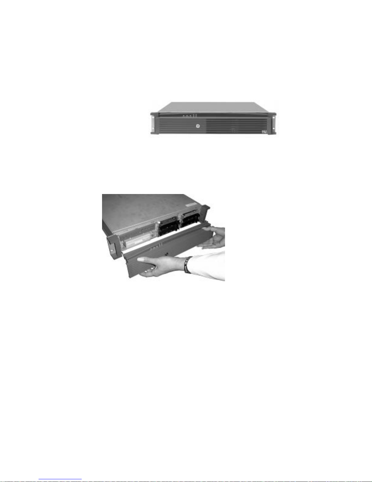
ISP2150
Congratulations on the purchase of your new I ntel® ISP2150 system. This Quick St art introduces you to
your new system, guides you through rack kit instal lation, and helps you get the system started.
The following procedures describe how operate the system’s front bezel, which covers the front panel
controls and indicators. For a description of the front panel features, refer to Front Panel Controls and
Indicators.
Opening and Closing the Front Bezel
With the bezel open you have access to all
of your system's front panel functions and
indicators. With the bezel closed you can
protect critical functions and still view the
system's indicators.
To open the bezel, do the following:
1. Stand in front of the chassis and grasp
the edges of the bezel from each side.
2. Gently pull the bezel towards you
until it begins to separate from the
chassis.
3. As the bezel separates from the
chassis, allow it to swing to its open
position situated below the chassis.
To close the bezel, gently raise it upwards.
The hinging mechanism will guide the
bezel into the correct position where it will
snap shut.
8 ISP2150 2U Rack Server Platform Quick Start Gui de
Page 7

Locking and Unlocking the Front Bezel
The bezel can be locked and unlocked to prevent unwanted access to the system.
To lock the bezel:
1. Remove the keys from inside the bezel (they should be taped to the inside).
2. Close the bezel and insert the key into the lock. Turn the lock counterclockwise until it stops (about a
quarter turn). The bezel is now locked and cannot be opened.
To unlock the bezel, insert the key into the lock and turn the lock clockwise until it stops (about a quarter
turn). The bezel is now unlocked and can be opened again.
Attaching and Removing the Front Bezel
The front bezel can be installed or removed from the system.
To attach the bezel:
1. With the LED light tunnel s located at the top of the bezel, push in the arms on either side of the bezel
far enough so that the tabs on the ends of the arms can be inserted into the holes in the chassis.
2. Insert the tabs into the holes in the handles on the chassis. Make sure the t abs on each side of the
bezel are completely in the holes in the handles.
To remove the bezel:
1. With the bezel opened, gently push the metal hinge arms located on each side of the bezel in towards
the middle of the unit.
2. Push the arms far enough in so that the tabs on the end of the ar ms are completely out of the holes in
the handles on the chassis. The bezel should now be able to be removed.
3. The bezel should now be able to open and close easily and completely.
Installation
Follow these instructions to get your sever to the point where you can load an operating system on it.
Open the Cover
1. Loosen the three screws on the rear of the system.
2. Pull the cover back and remove it from the chassis.
ISP2150 2U Rack Server Platform Quick Start Gui de 9
Page 8
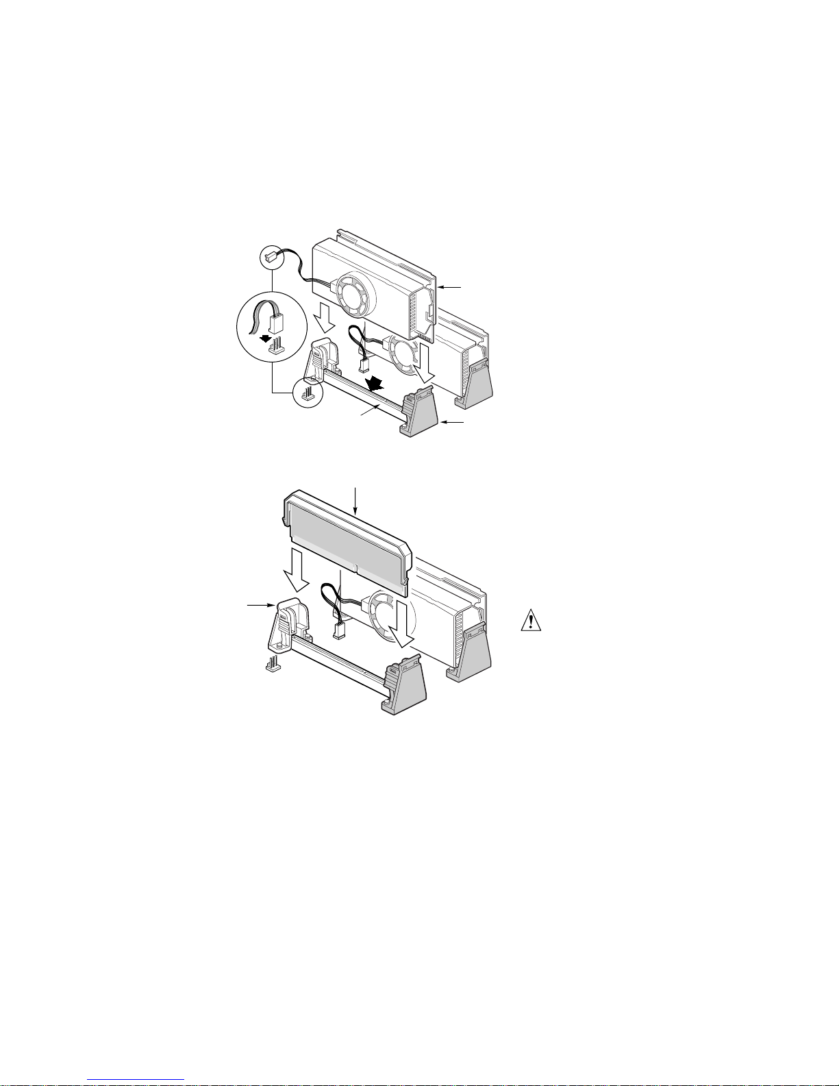
Installing a Microprocessor
The server supports up to two Intel
®
Pentium® II or Pentium III processors (with 100 MHz system bus).
If you are installing two processors, make sure they are the same speed, voltage, and stepping.
1. Remove the new processor from its
anti-static package and place it on a
grounded, static free surface or
conductive foam pad.
A
E
F
2. Attach the small end of the power
cable to the fan connector on the
S.E.C. cartridge, then attach the large
end (B) to the 3-pin connector on the
server board.
C
D
A
B
OM09315
3. Orient the processor so that the heat
sink faces the I/O connectors. Slide
the processor into the retention module.
Push down firmly, with even pressure
on both sides of the top, until the
processor is seated.
4. To lock in the processor, push the
latches inward on the retention module
until they click into place. The latches
must be secured for proper electrical
connection of the processor.
5. After you have installed the processor,
you must configure its speed in BIOS
set-up.
B
CAUTION, Single-Processor
Configurations
If you install only one processor in a
system, it must go in the primary
connector (closest to the DIMM
sockets). With a single-processor
OM09328
configuration, you mus t i nstall a
termination board and termination
latch assembly (A ) i n t he em pty
secondary connector (B) t o ensure
proper operation of your system. A
termination board is provided with
your system.
10 ISP2150 2U Rack Server Platform Quick Start Gui de
Page 9
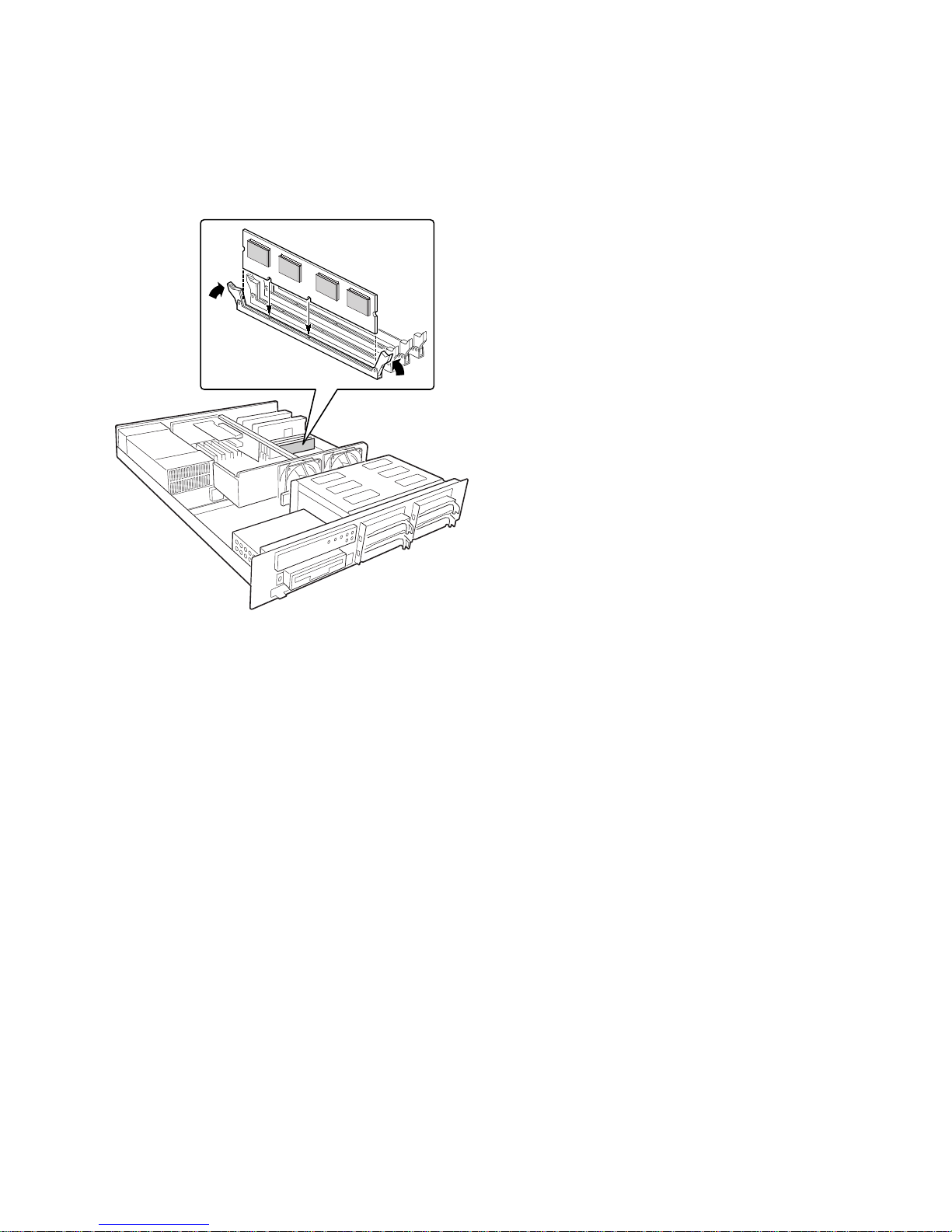
Installing Memory
The server only supports 100 MHz
PC/100-compliant S D RAM.
• Install from 32 MB to 2 GB of
unbuffered memory, using up to four
single or double-banked DIMMs
Or
• Install from 32 MB to 2 GB of
registered memory, using up to four
single or double-banked DIMMs
OM09318
ISP2150 2U Rack Server Platform Quick Start Gui de 11
Page 10

Installed DIMMs must be the same speed and eit her all registered or all unbuffered. For a list of support ed
memory, call your service representative or visit the Intel Support website:
http://support.intel.com/support/motherboards/server/l440gx/compat.htm
CAUTION
Use extreme care when installing a DIMM. Applying too much pressure can damage the socket.
DIMMs are keyed and can be ins erted in only one way.
Mixing dissimil ar m etals may cause later memory failures res ul t i ng i n data corruption. Only install
DIMMs with gold-plated edge c onnectors in gold-plated sockets.
To install your memory:
1. Open your server.
2. Holding the DIMM only by its edges, remove it from its anti-static package.
3. Orient the DIMM so that the two notches in the bottom edge of the DIMM align with the keyed
socket.
4. Insert the bottom edge of the DIMM into the socket, and press down firmly on the DIMM until it
seats correctly.
5. Gently push the plastic ejector levers on the socket ends to the upright position.
6. Repeat the steps to install each DIMM.
7. Ensure that no cables are protruding from the server chassis and then close the server.
8. Connect all external cables and the power cord to the server.
9. Turn on the monitor and then the server.
12 ISP2150 2U Rack Server Platform Quick Start Gui de
Page 11

Installing a Hard Drive
BA
E
D
Your server does not include a hard
drive. You must purchase them
separately and install them. The
server has four hot-swappable SCSI
hard drive bays.
1. Remove the drive carrier(s) from
the drive bays by unclipping the
retention lever on the right side of
the handle. Pull the retention
lever toward you until the tab end
(B) of the lever is free of the
OM09317
housing slot (A). Pull the drive
forward and out of the housing.
2. Remove the hard drive from its
wrapper and place it on an antistatic surface.
3. Remove and save the four screws
(D) from the drive carrier/drive
slide track.
4. Align the drive holes to the holes
A
in the drive carrier slide track (C),
insert the screws that you
previously removed, and attach
B
the carrier (B) to the drive (A).
Make sure that the connector end
of the drive (E) is facing the back
of the carrier and the drive top is
facing upward before inserting the
screws.
C
OM09323
5. Slide the carrier/drive into the
chassis with the retention
mechanism extended in the open
position, then push the arm
towards the front of the chassis
until the lever tab clicks into the
chassis slot indicating that it is
closed.
ISP2150 2U Rack Server Platform Quick Start Gui de 13
Page 12

Installing Add-in Cards
B
this server. You must use the PCI
slots on the riser card. Do not use
You can only add two PCI cards to
A
C
any expansion slots on the server
board.
1. Remove the expansion slot
cover for the slot you wish to
use. Remove the thumbscrew
(B) holding the cover retention
bracket (A) to the chassis.
Remove the bracket from the
chassis.
2. Remove the expansion slot
cover (C) for the slot you wish
to use.
OM09325
14 ISP2150 2U Rack Server Platform Quick Start Gui de
Page 13

B
A
3. Remove add-in board from its
protective wrapper. Set
jumpers or switches according
to the manufacturer’s
instructions.
4. Hold board by its top edge or
upper corners. Firmly press it
into an open expansion slot on
the riser card. The tapered foot
of the board-retaining bracket
must fit into the mating slot in
the expansion slot frame.
Install the board component
side DOWN.
OM09326
✏ NOTE
If you are installing a full-length PCI card, slide the card guide in front of the fans before installing the
card.
5. Align the rounded notch in the retaining bracket (B) with the threaded hole in t he frame. The bracket
fits the space that was occupied by the slot cover.
✏ NOTE
If you are installing a f ul l -l ength PCI card, slide the card guide back into plac e. The back edge of the
card should be held in place by the rai l of the card guide.
6. Install the cover retention bracket and thumbscrew.
ISP2150 2U Rack Server Platform Quick Start Gui de 15
Page 14

Installing a Slim-Line CD-ROM Drive
C
D
Your server does not come with an
integrated slim-line CD-ROM
drive. You must purchase one
separately and install it.
1. Remove the drive from its
protective wrapper, and place
A
it on an anti-static surface.
2. Set any jumpers and/or
switches on the drive
according to the drive
OM09348
manufacturer’s instructions.
3. Attach the CD-ROM drive to
the CD tray using the
mounting screws (A) supplied
with the system.
4. Remove the screws that hold
A
B
OM09319
the filler panel to the front of
the chassis and slide out the
panel.
5. Slide the slim-line CD tray
into the CD-ROM bay. It is
recommended that you first
remove the diskette drive in
the section “Removing the
Diskette Drive”.
6. Connect the CD-ROM IDE
cable (A) and power
(B) cables to the connector at
the back of the CD tray.
7. Reinstall the diskette drive in
the section “Re-Installing the
Diskette Drive”.
8. Insert the recessed retention
screws (C) through the access
holes in the top of the drive
bay housing.
9. Insert the retention screw (D)
on the front of the chassis.
16 ISP2150 2U Rack Server Platform Quick Start Gui de
Page 15

Removing a Diskette Drive
1. Disconnect the power (B) and
signal (A) cables from the
diskette drive. The connectors
are keyed for ease in
reconnecting them to the
drive.
2. Remove and save the screws
A
B
(C) that secure the diskette
drive carrier to the front of the
chassis.
3. Slide the drive carrier out the
front of the chassis.
4. Remove and save the screws
from the sides of the drive
carrier.
5. Pull the drive out of the carrier
and place the drive in an antistatic protective wrapper if
you are not reinstalling it.
C
Re-Installing a Diskette Drive
OM09316
1. Remove the 3.5-inch diskette drive from its protective wrapper, and place it component-side up on an
anti-static surface.
2. Install the drive into the drive car r ier and secure it with the screws that you removed.
3. Slide the drive carrier through t he f r ont of the chassis.
4. Secure the drive carrier to the front of the chassis with the screws you removed earlier.
5. Connect the signal and power cables to the drive according to the manufacturer’s specifications.
Close the Cover
1. Place the cover on the chassis and slide it forwards as far as possible. The sides and front of the cover
fit inside the chassis.
2. Tighten the three screws on the rear of the chassis.
ISP2150 2U Rack Server Platform Quick Start Gui de 17
Page 16

Installing the Front Bracket and Racking Your System
The ISP2150 system comes with mounting bracket hardware that allows you to install it into cabinets and
relay racks. The following procedures describe how to mount the ISP2150 system i n each t ype of chassis.
CAUTION
Some racks and cabinets may not support the inst al l at i on of the system. Before installing the
system, be sure to refer to the specifications provided by the manufacturer to insure proper
mounting configurations and m aximum specified loads for the rack or cabinet are not exceeded.
Installing the Front Bracket in a Cabinet
1. Attach the left and right front brackets
to the system. Your system comes
with left and right front brackets (A)
and mounting bolts (B) to attach them
to the system. Mount the brackets to
the sides of the system with the bracket
flange flush with the front panel.
2. Attach the rear support washer to the
system. The system also comes with
two support washers (C). Mount one
on each side towards the rear panel of
the system.
B A C
OM09334
18 ISP2150 2U Rack Server Platform Quick Start Gui de
Page 17

3. Mount the back support bracket to the
cabinet. Left (A) and right and left
rear mounting brackets also come with
the system. Mount the rear brackets in
the desired position in the cabinet using
the supplied mounting bolts (C)
supplied by the cabinet manufacturer.
4. Slide the system into the back support
bracket. After attaching the rear
brackets, slide the system into the rack
using the support washers as rollers.
5. Mount the front bracket to the cabinet.
To complete the installation, bolt the
system’s front brackets to the cabinet
using the mounting bolts (A) suppl ied
by the cabinet manufacturer.
AC B
OM09336
AA
OM09346
ISP2150 2U Rack Server Platform Quick Start Gui de 19
Page 18

Installing the Front Bracket in a Center-Mount, Relay Rack
1. Attach the left and right front brackets
to the system. Your system comes
with left and right front brackets (A)
and mounting bolts (B) to attach them
to the system. Mount the brackets
mid-way down the sides of the system
as shown in the figure.
✏ NOTE
You can also mount the brack et so
that the flange is flush with the front
panel.
2. Mount the bracket to the center channel
of the relay rack. To complete the
installation, bolt the system’s front
brackets to the cabinet using the
mounting bolts (A) supplied by the
cabinet manufacturer.
BA
OM09335
A
A
OM09347
20 ISP2150 2U Rack Server Platform Quick Start Gui de
Page 19

Installing the Rail Kit and Racking Your System (Optional Accessory)
The rail kit that comes with your system
allows you to install it into a four -post,
D
network server cabinet (e.g. APC
Netshelter). If the cabinet is not of this
general type, you will have to purchase a
separate rail kit that is speci fic to your
cabinet.
Follow these steps to install the rail kit and
place your system into the cabinet.
1. Assemble tools and miscellaneous
parts. You will need a Phillips
screwdriver and assorted lock washers
and nuts.
A B C
2. Remove the inside piece (C) from both
sides of the rail system. To remove an
inside piece of the rail system, slide the
part as far out as you can. This action
reveals a brass colored finger tab (D)
that when depressed allows you to
C
completely separate the inside rail
piece from the outer (A) and middle
(B) rail pieces.
3. Align each inside rail (A) to a side of
the chassis. Be sure that the flat end of
the inside rail is toward the front of the
chassis and that the brass colored
finger tab (D) is facing outward. With
A
the holes in the chassis (C) aligned
with the holes in the rail, fasten the rail
using the largest screws (B) supplied
with the rail kit.
DD
OM09132
D
B
OM09133
ISP2150 2U Rack Server Platform Quick Start Gui de 21
Page 20

4. Here is a combination side and rear
view of the chassis after the right
inside rail has been attached.
5. Locate the front and rear rail brackets
for one side of the rail kit. One pair (A
and B) exists for each side of the
cabinet rack.
6. Attach all four rail brackets to the
cabinet rack. Be sure that the sharper
angled side of each bracket is facing up
(C). Use eight mounting screws (D)
provided by the manufacturer of the
cabinet rack. In the illustration to the
right, the left photo (A) shows the leftfront bracket attached to the cabinet,
while the right photo (B) shows the
left-rear bracket. (The photo shows the
rails inside the brackets. You should
not have the rails attached inside the
brackets yet.)
A
B
OM09145
C C
D
A
D
B
OM09142
22 ISP2150 2U Rack Server Platform Quick Start Gui de
continued
Page 21

7. Attach the side rail system’s outer
pieces (total of two) to the rail brackets
you installed in step six.
To attach the front part of an outer piece
to a rail bracket, you must reveal the
access hole (A) by sliding the innermost
piece toward the back. Once you see the
access hole, align it with the slot in the
rail bracket such that you can secure the
bolt. Do not tighten the nut and bolt
until you have aligned the rear portion
of the rail system (see the next step).
C
A
B
OM09138
8. To attach the rear part of the rail system
to the rear rail bracket (A), slide the rail
system within the rail brackets such that
you can place a bolt through the rail’s
hole (B) and into the rail bracket’s slot.
Loosely tighten the bolt and nut. You
should be able to slide the entire rail
system back and forth in the rail
brackets. When you have centered the
rails in the bracket, tighten the fastening
bolts and nuts.
C
A
B
OM09144
ISP2150 2U Rack Server Platform Quick Start Gui de 23
Page 22

9. Extend the right and left rails (A)
so they fully extend in front of the
cabinet rack. The rail system is
now ready to receive the chassis.
A
A
OM09141
10. Lift the chassis with its front facing
you and carefully guide the inner
rail (A), which is mounted to the
chassis system, into the outer
pieces (B) you attached in previous
steps. Gently move the system
evenly towards the rear of the
cabinet. Be sure to depress the
brass colored finger tabs located in
the center of each inner side rail
piece as you slide the chassis back.
11. With the chassis fully inserted into
the cabinet rack, you can easily
access both the front and rear of the
system. The photo to the right
shows the system from the rear
fully inserted into the cabinet.
A
B
OM09143
24 ISP2150 2U Rack Server Platform Quick Start Gui de
Page 23

Technical Reference
Front Panel Controls and Indicators
A E
B C
D F G I
L K JM
H
OM09320
A. Power button
B. Sleep button
C. Reset button
D. Power LED
E. NIC activity LED
F. Fail LED
G. Disk activity/fail LEDs
H. Hard drive bay
I. Hard drive eject lever
J. CDROM drive bay
K. Diskette eject button
L. Diskette drive
M. Diskette activity LED
ISP2150 2U Rack Server Platform Quick Start Gui de 25
Page 24

Back Panel Connectors
A
B C
K IJ H G F E
D
OM09321
A. Mouse connector
B. Parallel port connector
C. PCI expansion slots
D. AC input power connector
E. Power supply fault indicator
F. Video connector
G. USB connectors
H. RJ45 network connector
I. Serial port connector (Com 1)
J. Serial port connector (Com 2)
K. Keyboard connector
NIC LED Color If it’s on If it’s blinking If it’s off
Orange 100 Mbps network
connection.
Green Linked to network, no
network traffic.
26 ISP2150 2U Rack Server Platform Quick Start Gui de
NA 10 Mbps network connection.
Linked to network, sending
or receiving data.
Not linked to network.
Page 25

Jumpers
Nine 3-pin jumper blocks that control vari ous configuration options, as shown in the figure below. Refer
to the ISP2150 2U Rack Server Platform Product Guide for more information.
Jumper
Block
WOL ENABLE
J5A2
1
Jumper Name Pins
(default in bold) What it does at system reset
BMC
WR EN
1
BIOS WR EN
J2J1
RCVRY BOOT
PSWD CLR
CMOS CLR
1
J4J2
OM08429
J3J1
BMC FRC UP
INT DET
FRB
1
J5A2 WOL ENABLE 1-2, Disabled Disables Wake On LAN†. If your power supply
does not provide 0.8 A of +5 V S tandby current,
you must move the WOL Enable j umper to this
position.
2-3, Enabled Enables Wake On LAN.
J4J2 BMC WR EN 1-2, Protect BMC boot block is writ e protected.
2-3, Erase/Program BMC boot block is eras abl e and program m abl e.
J3J1 FRB 1-2, Enable FRB operation is enabled (system boots from
processor 1 if processor 0 does not respond).
2-3, Disable FRB is disabled.
J3J1 INT DET 5-6, Enable Switch installed on c hassis indicates when cover
has been removed.
6-7, Disable Chassis intrusion switch is by passed.
J3J1 BMC FRC UP 9-10, Normal System boots normally.
10-11, Program System attempts to update BMC firmware.
J2J1 CMOS CLR 1-2, Protect Preserves the contents of NVRAM.
2-3, Erase Replaces the contents of NVRAM with the
manufacturing default settings.
continued
ISP2150 2U Rack Server Platform Quick Start Gui de 27
Page 26

Jumper
Block
J2J1 PSWD CLR 5-6, Protect Maintains the current system password.
J2J1 RCVRY BOOT 9-10, Normal System attempts to boot using the BI OS stored
J2J1 BIOS WR EN 13-14, Protect BIOS boot block is write-protected.
Jumper Name Pins
(default in bold) What i t does at system reset
6-7, Erase Clears the password.
10-11, Recovery BIOS attempts a recovery boot, loading BIOS
14-15,
Erase/Program
in flash memory.
code from a floppy diskette into the flash device.
This is typicall y used when the BIOS code has
been corrupted.
BIOS boot block is eras abl e and programmable.
CAUTION
Moving either of the boot bloc k write protect jumpers (J4J2-BMC WR EN or J2J 1- B IOS WR EN)
may cause irrevocable damage to the server board. Only move these jumpers when direc t ed to by
your customer service representative.
✏ NOTE
If you wish to use the WOL feature, your power supply must provide 0.8 A of +5 V S tandby current.
If it does not, your server board may not boot. Move the WOL Enable jumper to the Di s abl ed
position if your power supply does not provide the required current.
28 ISP2150 2U Rack Server Platform Quick Start Gui de
Page 27

Server Board Components
A
II
HH
GG
FF
EE
DD
CC
BB
AA
Z
Y
A. Fansink connector 2
B. Secondary processor
C. Fansink connector 1
D. Primary processor
E. DIMM slots
F. Main power connector
G. ATX aux power connector
H. Fan connector FAN2A
I. Floppy connector
J. IDE connectors
K. ATX f ront panel connector
L. Front panel connector, 16 pin
M. Battery
N. Isolated Server Management
(ISOL) IMB connector
O. Jumper block
P. Jumper block
Q. Fan connector 1
B
C
D
X
R. Ultra wide SCSI connector
S. Server Moni tor Module (SMM) connector
T. External Wake on LAN connect or
U. Ultra2/LVD SCSI connector
V. Hard drive LED connector
W. Intelligent Chassis Management Bus (I CM B) header
X. ISA connector (do not install a card in this connect or)
Y. Chassis intrusion connector
Z. PCI connectors (do not ins t al l cards in these connectors)
AA. Riser card connector
BB. Fan connector FAN2B
CC. Video connector
DD. USB connectors
EE. NIC connector
FF. Serial port connector
GG. Parallel port connector
HH. Serial port connector
II. Mouse/keyboard connectors
EFGH I J
RSTUVW
OM08561
K
L
M
N
O
P
Q
ISP2150 2U Rack Server Platform Quick Start Gui de 29
Page 28

Getting Help
World Wide Web
Support for this product may be found at the following URL:
Une assistance pour ce produit est disponible à l'adr e sse suivante:
Unterstützung zu diesem Produkt er halten Sie unter der folgenden Webadresse:
È possibile ottenere supporto per questo prodotto al seguente indirizzo:
Podrá encontrar asistencia para este producto en la siguiente dirección URL:
O suporte para este produto pode ser encontrado no seguinte URL:
http://www.intel.com/isp/
30 ISP2150 2U Rack Server Platform Quick Start Gui de
 Loading...