

Page 1

ISP2150 2U Rack Server Platform Product Guide
A Guide for Technically Qualified Assemblers of Intel® Identified Subassemblies/Products
Order Number: A09581-001
Page 2

Disclaimer
Intel Corporation (Intel) makes no warranty of any kind with regard t o this mat eri al, including, but not limited to, the implied
warranties of merchantability and fitness for a particular purpose. Intel assumes no responsibility for any errors that may
appear in this document. Intel makes no commitment to update nor to keep current the informati on cont ained in this
document. No part of this document may be copied or reproduced in any form or by any means without prior written consent
of Intel.
An Intel product, when used in accordance with its associated documentation, is "Year 2000 Capable" when, upon
installation, it accurately stores, di spl ays, processes, provides, and/or receives date data from, into, and between the
twentieth and twenty-first centuries, i ncl uding leap year calculations, provided that all other technology used in combinat ion
with said product properly exchanges date data with it.
†
Third party brands and names are the property of their respective owners.
Copyright © 1999, Intel Corporation.
Page 3

Contents
1 Description
Server Board Features......................................................................................................... 9
Front Panel Controls and Indicators........................................................................... 10
Back Panel Connectors............................................................................................. 11
Major System Elements............................................................................................. 12
Server Board Connector and Component Locations.................................................. 13
Processor........................................................................................................................... 14
Memory.............................................................................................................................. 14
440GX Host Bridge / Memory Controller............................................................................. 15
Peripherals......................................................................................................................... 15
Super I/O Chip........................................................................................................... 15
Add-in Board Slots ............................................................................................................. 16
Video.................................................................................................................................. 16
SCSI Controller .................................................................................................................. 16
IDE Controller..................................................................................................................... 17
Network Controller.............................................................................................................. 17
Keyboard and Mouse......................................................................................................... 18
ACPI .................................................................................................................................. 18
Server Management ........................................................................................................... 18
Baseboard Management Controll er (BMC)................................................................ 18
Emergency Management Port Console ..................................................................... 19
Platform Event Paging............................................................................................... 20
Software Security............................................................................................................... 20
Using Passwords....................................................................................................... 21
Secure Mode............................................................................................................. 21
Summary of Software Security Features.................................................................... 22
Checking the Power Cords................................................................................................. 23
Equipment Rack Precautions ............................................................................................. 24
2 Upgrading and Installing Server Components
Tools and Supplies Needed................................................................................................ 25
Warnings and Cautions...................................................................................................... 25
Bezel.................................................................................................................................. 27
Opening and Closing the Front Bezel ........................................................................ 27
Locking and Unlocking the Front Bezel...................................................................... 28
Attaching and Removing the Front Bezel................................................................... 28
Covers................................................................................................................................ 29
Opening the Cover..................................................................................................... 29
Closing the Cover...................................................................................................... 29
Processors......................................................................................................................... 30
Installing a Processor.................................................................................................31
Removing a Processor............................................................................................... 32
Memory.............................................................................................................................. 33
Installing DIMMs........................................................................................................ 33
iii
Page 4

Removing DIMMs...................................................................................................... 34
Peripheral Devices............................................................................................................. 35
Removing the Diskette Drive...................................................................................... 35
Re-installing the Diskette Drive.................................................................................. 36
Installing a Hard Drive................................................................................................ 36
Installing a Slim-line CDROM Drive ........................................................................... 38
Removing a CDROM Drive........................................................................................ 39
Add-in Cards ...................................................................................................................... 40
Installing Add-in Cards............................................................................................... 40
Power Supply..................................................................................................................... 42
Removing and Re-installing a Power Supply ............................................................. 42
System Mounts................................................................................................................... 43
Installing the Front Bracket and Racking the System................................................. 43
Installing the Rail Rack and Racking the System (Optional Accessory) ..................... 45
Replacing the Back up Battery ........................................................................................... 49
3 Configuration Software and Utilities
Hot Keys............................................................................................................................. 51
Power On Self Test (POST) ............................................................................................... 52
Using BIOS Setup.............................................................................................................. 53
Record Your Setup Settings....................................................................................... 53
If You Cannot Access Setup...................................................................................... 53
Starting Setup............................................................................................................ 54
Setup Menus ............................................................................................................. 54
Main Menu................................................................................................................. 55
Security Menu............................................................................................................ 61
Server Menu.............................................................................................................. 62
Boot Menu................................................................................................................. 65
Exit Menu................................................................................................................... 67
Using the System Setup Utility........................................................................................... 67
When to Run the System Setup Utility....................................................................... 68
What You Need to Do................................................................................................ 68
Running the SSU....................................................................................................... 69
Customizing th e SSU................................................................................................. 71
Launching a Task ...................................................................................................... 71
Resource Configuration Add-in (RCA) Window.......................................................... 72
Multiboot Options Add-in............................................................................................ 73
Security Add-in.......................................................................................................... 74
SEL Manager Add-in................................................................................................. 75
FRU Manager Add-in................................................................................................. 76
SDR Manager Add-in................................................................................................. 77
Exiting the SSU.......................................................................................................... 77
Platform Event Paging........................................................................................................ 78
Using Platform Event Paging..................................................................................... 78
Emergency Management Port Console.............................................................................. 79
How EMP Console Works.......................................................................................... 80
Requirements............................................................................................................ 82
Setting up the Server for the EMP............................................................................. 83
Main EMP Console Window....................................................................................... 84
iv ISP2150 2U Rack Server Platform Product Guide
Page 5

Server Control Operations......................................................................................... 85
Phonebook ................................................................................................................ 88
Management Plug-ins................................................................................................ 89
FRUSDR Load Utility.......................................................................................................... 92
When to Run the FRUSDR Load Utility...................................................................... 92
What You Need to Do................................................................................................ 92
How You Use the FRUSDR Load Utility..................................................................... 93
Upgrading the BIOS........................................................................................................... 95
Preparing for the Upgrade ......................................................................................... 95
Upgrading the BIOS................................................................................................... 97
Recovering the BIOS................................................................................................. 97
Changing the BIOS Language................................................................................... 98
Using the Firmware Update Utility......................................................................................98
Running the Firmware Update Utility.......................................................................... 98
Installing Video Drivers....................................................................................................... 99
Using the Adaptec SCSI Utility........................................................................................... 99
Running the SCSI Utility ............................................................................................ 99
4 Solving Problems
Resetting the System ....................................................................................................... 101
Fault Resilient Booting...................................................................................................... 101
Initial System Startup........................................................................................................ 101
Checklist.................................................................................................................. 102
Running New Application Software................................................................................... 102
Checklist.................................................................................................................. 102
After the System Has Been Running Correctly................................................................. 103
Checklist.................................................................................................................. 103
More Problem Solving Procedures................................................................................... 104
Preparing the System for Diagnostic Testing........................................................... 104
Monitoring POST..................................................................................................... 104
Verifying Proper Operation of Key System Lights.................................................... 104
Confirming Loading of the Operating System........................................................... 104
Specific Problems and Corrective Actions........................................................................ 105
Power Light Does Not Light..................................................................................... 105
No Characters Appear on Screen............................................................................ 105
Characters Are Distorted or Incorrect....................................................................... 106
System Cooling Fans Do Not Rotate Properly......................................................... 106
Diskette Drive Activity Light Does Not Light............................................................. 107
Hard Disk Drive Activity Light Does Not Light .......................................................... 107
CD-ROM Drive Activity Light Does Not Light ........................................................... 107
Cannot Connect to a Server..................................................................................... 108
Problems with Network............................................................................................ 108
PCI Installation Tips................................................................................................. 109
Problems with Application Software.................................................................................. 109
Bootable CD-ROM Is Not Detected.................................................................................. 109
Error and Informational Messages.................................................................................... 110
Port-80 Codes and Countdown Codes..................................................................... 110
Content v
Page 6

5 Technical Reference
Connectors....................................................................................................................... 112
ATX Style Front Panel Connector............................................................................ 113
Main Power Connector ............................................................................................ 114
Fan Interface ........................................................................................................... 114
Server Board Jumpers...................................................................................................... 115
General Procedure to Change Jumper Setting........................................................ 116
CMOS Jumper......................................................................................................... 117
Password Jumper.................................................................................................... 117
Recovery Boot Jumper............................................................................................ 118
Boot Block Write Protect Jumper............................................................................. 118
FRB Timer Enable Jumper ...................................................................................... 119
Chassis Intrusion Detection Jumper......................................................................... 119
6 Product Regulation and Certification Information
Regulatory Information Safety Compliance For Information Technology Equipment ........ 121
EMC Compliance..................................................................................................... 121
Regulatory Compliance Markings............................................................................ 121
Electromagnetic Compatibility Notices..................................................................... 122
Lithium Battery Replacement................................................................................... 124
Equipment Rack Precautions................................................................................... 125
Cautions........................................................................................................................... 126
Use Only for Intended Applications .......................................................................... 126
Power Cords............................................................................................................ 126
Warnings.......................................................................................................................... 127
WARNING: English (US) ........................................................................................ 128
AVERTISSEMENT: Français.................................................................................. 130
WARNUNG: Deutsch.............................................................................................. 132
AVVERTENZA: Italiano.......................................................................................... 134
ADVERTENCIAS: Español..................................................................................... 136
7 Equipment Log and Power Consumption Worksheets
Equipment Log................................................................................................................. 138
Current Usage......................................................................................................... 140
Calculating Power Consumption.............................................................................. 140
Index.................................................................................................................................... 143
Figures
1. Front View of ISP2150............................................................................................... 10
2. Front Panel Controls and Indicators........................................................................... 10
3. Back Panel Connectors............................................................................................. 11
4. Major System Elements............................................................................................. 12
5. Server Board Connector and Component Locations.................................................. 13
6. Opening the Bezel..................................................................................................... 27
7. Opening the Cover..................................................................................................... 29
8. Installing a Processor ................................................................................................ 31
9. Installing a Termination Board................................................................................... 32
10. Installing DIMMs........................................................................................................ 34
11. Removing the Diskette Drive from the Chassis.......................................................... 35
vi ISP2150 2U Rack Server Platform Product Guide
Page 7

12. Removing the Hard Drive Carrier from the Chassis...................................................36
13. Attaching the D rive to the Carri e r............................................................................... 37
14. Attaching a Slim-line CDROM Drive to the CDROM Tray .......................................... 38
15. Installing a Slim-line CDROM Drive...........................................................................39
16. Removing the Slot Cover Retention Bracket.............................................................. 40
17. Installing an Add-in Card ........................................................................................... 41
18. Replacing the Power Supply...................................................................................... 42
19. Mounting the Front Brackets and Support Washers................................................... 43
20. Mounting the Back Support Brackets ......................................................................... 43
21. Mounting the Front Brackets to the Cabinet Chassis ................................................. 44
22. Mounting the Front Brackets Midway Along the System ............................................ 44
23. Mounting the Front Brackets to the Relay Rack......................................................... 44
24. Rail System............................................................................................................... 45
25. Aligning Rail to Chassis............................................................................................. 45
26. Chassis Rear and Side View ..................................................................................... 46
27. Rail Brackets ............................................................................................................. 46
28. Attaching Rail Brackets to Cabinet Rack.................................................................... 46
29. Attaching Outer Pieces to Rail Brackets.................................................................... 47
30. Attaching Rail System to Rear Rail Bracket............................................................... 47
31. Extending the Rails.................................................................................................... 48
32. Guiding Chassis into the Rack................................................................................... 48
33. Chassis Mounted into the Rack................................................................................. 48
34. Replacing the Lithium Battery.................................................................................... 50
35. System Setup Utility Main Window ............................................................................ 70
36. EMP Console in Command State.............................................................................. 80
37. EMP Console in Redirect State ................................................................................. 81
38. Connect Dialog.......................................................................................................... 86
39. Power On/Off Dialog.................................................................................................. 87
40. Reset Dialog.............................................................................................................. 87
41. Phonebook Dialog..................................................................................................... 88
42. Connector Locations................................................................................................ 112
43. ATX Style Front Panel Connector............................................................................ 113
44. Jumper Locations.................................................................................................... 115
Tables
1. Server Board Features ................................................................................................ 9
2. NIC LEDs.................................................................................................................. 11
3. Software Security Features........................................................................................ 22
4. Configuration Utilities ................................................................................................. 51
5. Hot Keys.................................................................................................................... 51
6. EMP Console Access Modes (Server configured for console redirection).................. 81
7. EMP Console Access Modes (Server not configured for console redirection)............ 82
8. ATX Style Front Panel Connector Pinout................................................................. 113
9. Main Power Connector Pinout................................................................................. 114
10. Fan Connector Pinout.............................................................................................. 114
11. Server Board Jumper Summary............................................................................... 115
12. Power Usage Worksheet 1...................................................................................... 141
13. Power Usage Worksheet 2...................................................................................... 141
Content vii
Page 8

viii ISP2150 2U Rack Server Platform Product Guide
Page 9

1 Description
Server Board Features
Table 1. Server Board Features
Feature Description
Processor Installed: Up to two Intel® Pentium® II or Pentium III processors operating at 1.8
V to 3.5 V. The server board’s voltage regulator is automatically programmed by
the processor’s VID pins to provide the required voltage.
Memory (DRAM) Four 72 bit sockets for 168-pin, gold contact, 100 MHz, PC/100 compliant, ECC
or non-ECC, registered or unbuffered, SDRAM dual inline memory
modules (DIMM).
Video Memory Installed: 2 MB of video memory.
PCI bus Two standard PCI (PCI-33/32 bit) expansion slots on a riser card for add-in
boards. Embedded devices: video controller, Network Interface Controller
(NIC), and SCSI controller.
Server Management Thermal/voltage monitoring and error handling.
Real time clock/calendar (RTC).
Front panel controls and indicators (LEDs).
System Setup Utility (SSU).
Basic Input/Output System (BIOS), Power On Self Test (POST), and Setup
stored in flash memory.
Graphics Integrated onboard Cirrus Logic† CL-GD5480 super video graphics array
(SVGA) controller.
SCSI Adaptec† AIC-7896, supporting onboard Ultra2 (LVDS) Wide and Ultra-wide
SCSI interfaces.
Network Integrated onboard NIC, an Intel® 82559 single chip PCI LAN controller for 10 or
100 Mbps TX Fast Ethernet networks. RJ-45 Ethernet connector and indicator
LEDs at I/O back panel.
System I/O PS/2-compatible keyboard and mouse ports, 6 pin DIN.
Advanced parallel port, supporting Enhanced Parallel Port (EPP) level 1.7 and
1.9, ECP, compatible 25 pin.
VGA video port, 15 pin.
Two serial ports, 9 pin.
RJ-45 Ethernet port.
Two USB ports.
9
Page 10

Front Panel Controls and Indicators
The front panel controls and indicators are located behind the front bezel of the ISP2150 as shown
in Figure 1. To access the panel, grasp the bezel at its edges and gently pull it towards you.
Figure 1. Front View of ISP2150
Figure 2 presents the controls and indicators for the unit.
A E
B C
D F G I
H
L K JM
Figure 2. Front Panel Controls and Indicators
A. Power button H. Hard drive bay
B. Sleep button I. Hard drive eject lever
C. Reset button J. CDROM drive bay
D. Power LED K. Diskette eject button
E. NIC activity LED
F. Fail LED
G. Disk activity/fail LEDs
L. Diskette drive
M. Diskette activity LED
OM09320
10 ISP2150 2U Rack Server Platform Product Guide
Page 11
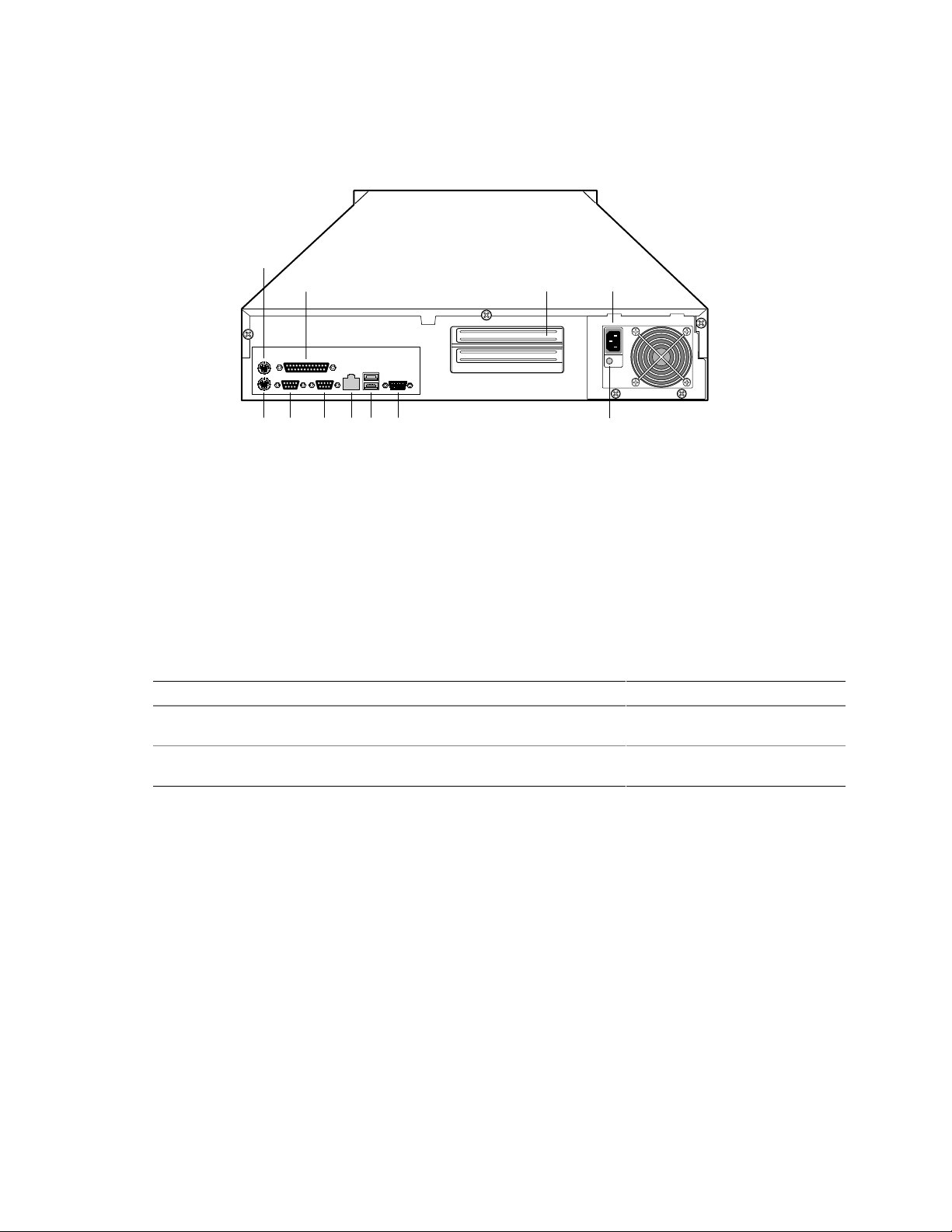
Back Panel Connectors
A
B C
K IJ H G F E
A. Mouse connector G. USB connectors
B. Parallel Port connector H. RJ45 Network connector
C. PCI Expansion slots I. Serial port connector (COM1)
D. AC input power connector J. Serial port connector (COM2)
E. Power supply fault indicator K. Keyboard connector
F. Video connector
D
OM09321
Figure 3. Back Panel Connectors
Table 2. NIC LEDs
NIC LED Color If it’s on If it’s blinking If it’s off
Orange 100 Mbps network
connection
Green Linked to network,
no network traffic
NA 10 Mbps network connection
Linked to network, sending or
receiving data
Not linked to network
Description 11
Page 12
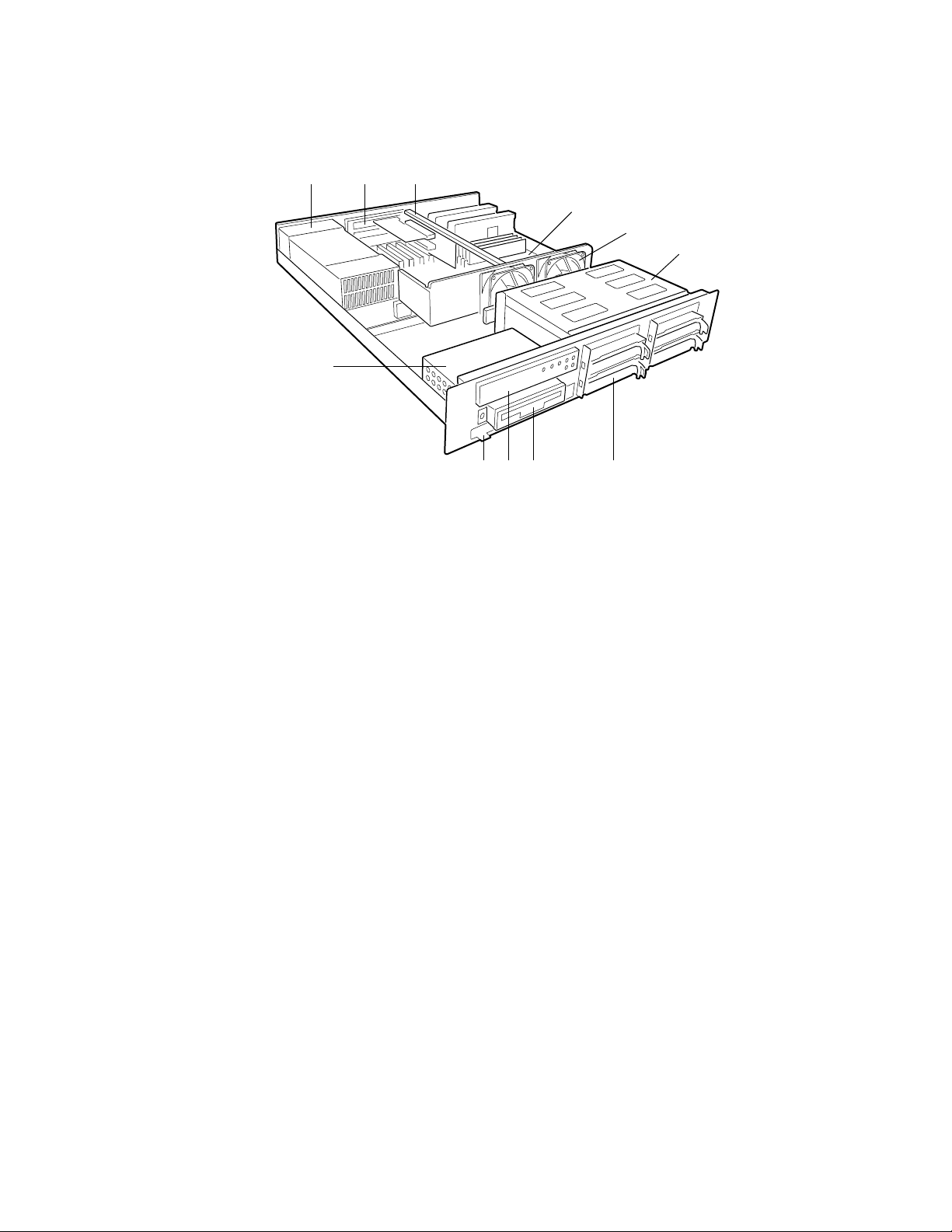
Major System Elements
A B C
K
A. Power supply G. Hard drive carrier
B. Expansion slot covers H. Diskette drive
C. PCI riser card bracket I. Front panel
D. Server board J. CDROM drive bay cover
E. Fan K. Floppy/CDROM housing
F. Hot-swap drive bay
D
E
F
GJ HI
OM09322
Figure 4. Major System Elements
12 ISP2150 2U Rack Server Platform Product Guide
Page 13
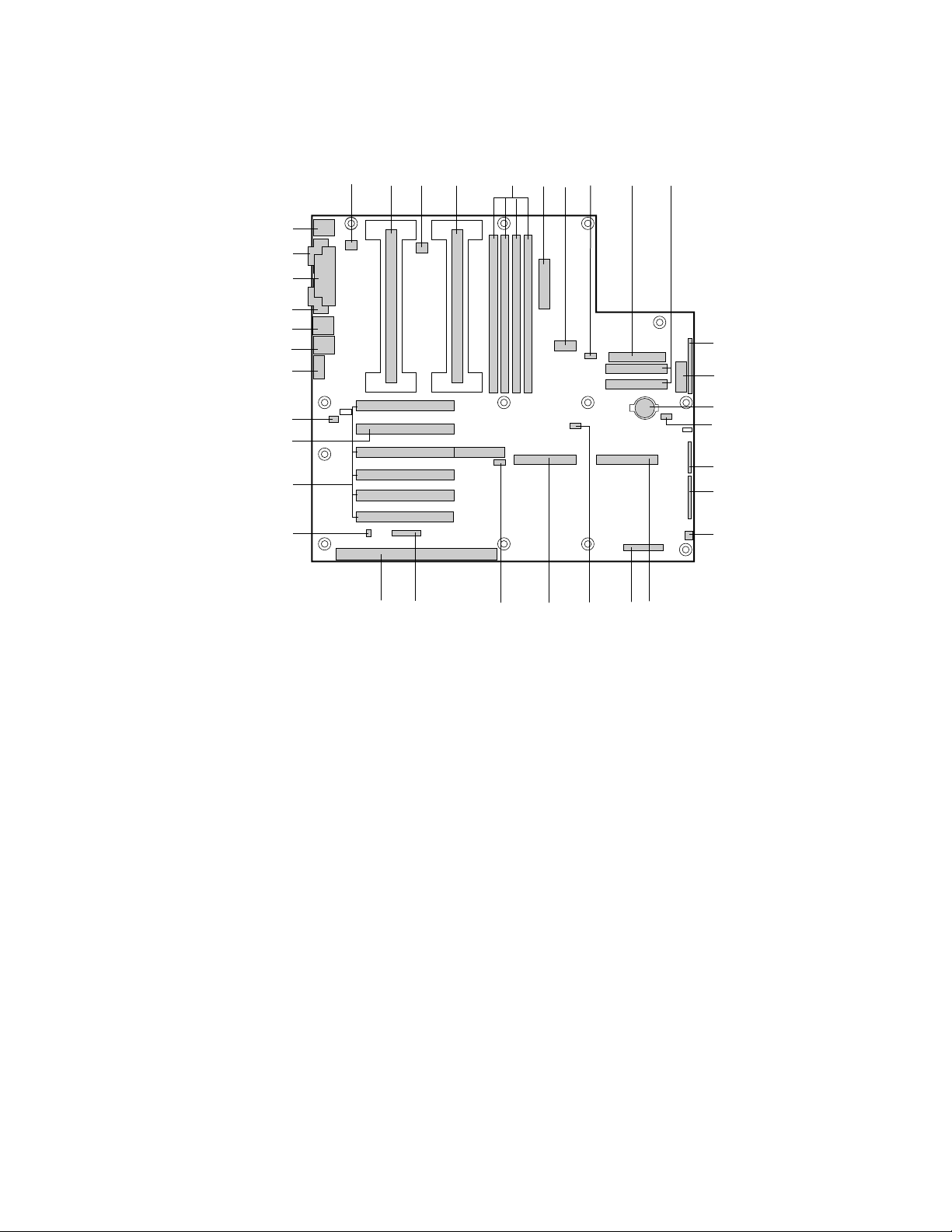
Server Board Conne ctor and Component Locations
HH
GG
FF
EE
DD
CC
BB
AA
II
Z
Y
B
A
C
D
EFGH I J
K
L
M
N
O
P
Q
X
RSTUVW
OM08561
Figure 5. Server Board Connector and Component Locations
A. Fansink connector 2
B. Secondary processor
C. Fansink connector 1
D. Primary processor
E. DIMM slots
F. Main power connector
G. ATX aux power connector
H. Fan connector FAN2A
I. Floppy connector
J. IDE connectors
K. ATX front panel connector
L. Front panel connector, 16 pin
M. Battery
N. Isolated Server Management
(ISOL) IMB connector
O. Jumper block
P. Jumper block
Q. Fan connector 1
R. Ultra wide SCSI connector
S. Server Monitor Module (SMM)
connector
T. External Wake on LAN
U. Ultra2/LVD SCSI connector
V. Hard drive LED connector
W. Intelligent Chassis Management Bus
(ICMB) header
X. ISA connector (do not install a card in
this connector)
Y. Chassis intrusion connector
Z. PCI connectors (do not install cards in
these connectors)
AA. Riser card connector
BB. Fan connector FAN2B
CC. Video connector
DD. USB connectors
EE. NIC connector
FF. Serial port connector
GG. Parallel port connector
HH. Serial port connector
II. Mouse/keyboard connectors
†
connector
Description 13
Page 14

Processor
Each Pentium II or Pentium III processor is packaged in a cartridge. The cartridge includes the
processor core with an integrated 16 KB primary (L1) cache, the secondary (L2) cache, and a back
cover.
The processor implements the MMX
™
the 8086, 80286, Intel386
processors. The processor’s numeric coprocessor significantly increases the speed of floating point
operations and complies with ANSI/IEEE standard 754-1985.
Each processor cartridge connects to the server board through a 242-pin slot 1-edge connector. A
retention module attached to the server board secures the cartridge. Depending on the
configuration, your server may have one or two processors.
The processor external interface is MP (Mu lti-P roc essor ) rea dy and opera tes at 100 MHz. The
processor contains a local APIC (Advanced Programmable Interrupt Controller) section for
interrupt handling in MP and UP (Uni-Processor) environments.
The second level cache is located on the substrate of the S.E.C. cartridge. The cache includes burst
pipelined synchronous static RAM (BSRAM).
, Intel486™, Pentium, Pentium Pro, Pentium II, and Pentium III
™
technology and maintains full backward compatibility with
Memory
Only 100 MHz PC/100 ECC or Non-ECC SDRAM is supported by the server board. Memory is
partitioned as four banks of SDRAM DIMMs, each providing 72 bits of non-interleaved memory
(64 bit main memory plus ECC):
• Install from 64 MB to 2 GB of memory, using registered DIMMs.
• Install from 32 MB to 1 GB of memory, using unbuffered DIMMs.
Memory should be added in order from slot 1 to slot 4.
NOTE
✏
Do not mix registered and unbuffered memory. Non ECC memory may be
installed but ECC memory is recommended in a server environment. Mixing
Non-ECC memory and ECC memory causes all ECC features to be disabled.
The controller automatically detects, sizes, and initializes the memory array, depending on the type,
size, and speed of the installed DIMMs, and reports memory size and allocation to the server via
configuration registers.
14 ISP2150 2U Rack Server Platform Product Guide
Page 15

NOTE
✏
Use DIMMs that have been tested for compatibility with the server board.
Contact your sales representative or dealer for a current list of approved
memory modules. Check the Intel Customer Support web site for the latest
tested memory list:
http://support.intel.com/support/motherboards/server/L440gx/compat.htm
440GX Host Bridge / Memory Controller
The ISP2150 is designed around the Intel® 82440GX AGPSet (440GX). This device provides
100 MHz processor host bus interface support, DRAM controller, PCI bus interface, AGP interface
(used on LB440GX for PCI-66/5V), and power management functions. The host bus/memory
interface in the 440GX is optimized for 100 MHz operation, using 100 MHz SDRAM main
memory. The PCI interface is PCI 2.1-compliant, providing a 33 MHz / 5V signaling environment
for embedded controllers and slots in the riser card. The 440GX memory controller supports up to
2 GB of ECC or Non-ECC memory, using PC/100 compliant Synchronous DRAM (SDRAM)
devices on DIMM plug-in modules. ECC can detect and correct single-bit errors, and detect
multiple-bit errors.
Peripherals
Super I/O Chip
The National† 87309 device supports two serial ports, one parallel port, diskette drive,
PS/2-compatible keyboard and mouse. The server board provides a connector interface for
each port.
Serial Ports
Each serial port can be set to one of four different COMx ports and can be enabled separately.
When enabled, each port can be programmed to generate edge or level sensitive interrupts. When
disabled, serial port interrupts are available to add-in boards.
Parallel Port
The 87309 provides one IEEE 1284-compatible 25 pin bi-directional EPP (supporting levels 1.7
and 1.9). BIOS programming of the 87309 registers enable the parallel port and determine the port
address and interrupt. ECP mode is supported with 2 possible DMA channels. When disabled, the
interrupt is available to add-in boards.
Description 15
Page 16

Add-in Board Slots
You can only add two PCI cards to this server. You must use the PCI slots on the riser card. Do
not use any expansion slots on the server board.
The server board has two full length standard PCI connectors on the riser card. PCI features:
• Bus speed up to 33 MHz
• 32 bit memory addressing
• 5 V signaling environment
• Burst transfers of up to 133 Mbps
• 8, 16, or 32 bit data transfers
• Plug and Play ready
• Parity enabled
Video
The onboard, integrated Cirrus Logic CL-GD5480 64 bit VGA chip contains an SVGA controller
†
that is fully compatible with these video standards: CGA, EGA, Hercules
and VGA. The standard configuration comes with 2 MB of 10 ns onboard Synchronous Graphics
Memory (SGRAM). The video controller supports pixel resolutions of up to 1600 x 1200 and up to
16.7 Million colors.
Graphics, MDA LAN,
The SVGA controller supports analog VGA monitors (single and multiple frequency, interlaced
and non-interlaced) with a maximum vertical retrace non—interlaced frequency of 100 Hz.
You cannot add video memory to the server board. Depending on the environment, the controller
displays up to 16.7 M colors in some video resolutions. It also provides hardware accelerated bit
block transfers (BITBLT) of data.
SCSI Controller
The embedded Adaptec AIC-7896 dual function SCSI controller provides both Ultra2 (LVDS)
wide and Ultra wide SCSI interfaces as two independent PCI functions.
The SCSI bus is terminated on the server board with active terminators that cannot be disabled.
The onboard device must always be at one end of the bus. The device at the end of the cable must
be terminated. LVDS devices generally do not have termination capabilities. Non-LVDS devices
generally are terminated through a jumper or resistor pack. If your device does not have a
termination jumper or resistor pack, you must add a terminator to the end of the cable. A
terminator is not supplied with your board. You must purchase one separately.
The hot-swap backplane in the ISP2150 system provides termination for the LVD SCSI bus.
16 ISP2150 2U Rack Server Platform Product Guide
Page 17

IDE Controller
IDE is a 16 bit interface for intelligent disk drives with disk controller electronics onboard. The
PCI/ISA/IDE Accelerator, also known as PIIX4e, is a multifunction device on the server board that
acts as a PCI based Fast IDE controller. The device controls:
• PIO and IDE DMA/bus master operations
• Mode 4 timings
• Transfer rates up to 33 MB/s
• Buffering for PCI/IDE burst transfers
• Master/slave IDE mode
• Up to two devices per channel; two channels, IDE0 and IDE1
NOTE
✏
18 inch maximum length of IDE cable on each channel: You can connect
an IDE signal cable, up to a maximum of 18 inches each, to each
IDE connector on the server board. Each cable can support two devices, one
at the end of the cable and one 6 inches from the end of the cable.
Network Controller
The server board includes a 10BASE-T/100BASE-TX network solution based on the Intel 82559
single chip Fast Ethernet PCI Bus Controller. As a PCI bus master, the controller can burst data at
up to 132 MB/s. The controller contains two receive and transmit FIFO buffers that prevent data
overruns or underruns while waiting for access to the PCI bus. The controller has the following:
• 32 bit PCI bus master interface (direct drive of bus), compatible with PCI Bus Specification,
Revision 2.1
• Chained memory structure with improved dynamic transmit chaining for enhanced
performance
• Programmable transmit threshold for improved bus utilization
• Early receive interrupt for concurrent processing of receive data
• On-chip counters for network management
• Autodetect and autoswitching for 10 or 100 Mbps network speeds
• Support for both 10 Mbps and 100 Mbps networks, capable of full or half duplex, with
back-to-back transmit at 100 Mbps
The network status LEDs on the server board indicate:
• Transmit/receive activity on the LAN
• Valid link to the LAN
• 10/100 Mbps transfer mode
Description 17
Page 18

Keyboard and Mouse
The keyboard/mouse controller is PS/2-compatible. The server may be locked automatically if
there is no keyboard or mouse activity for a predefined length of time, if specified through the
System Setup Utility (SSU). Once the inactivity (lockout) timer has expired, the keyboard and
mouse do not respond until the previously stored password is entered.
ACPI
The ISP2150 supports the Advanced Configuration and Power Interface (ACPI) as defined by the
ACPI 1.0 and PC97 specifications. An ACPI aware operating system can put the system into a
state where the hard drives spin down, the system fans stop, and all processing is halted. However,
the power supply will still be on and the processors will still be dissipating some power, so the
power supply fan and processor fans will still run.
The ISP2150 supports sleep states s0, s1, s4, and s5. With future versions of
Microsoft
With future versions of Microsoft Windows NT
states s0, s1, s4, and s5.
• s0: Normal running state.
• s1: Processor sleep state. No context will be lost in this state and the processor caches will
• s4: Hibernate or Save to Disk: The memory and machine state are saved to disk. Pressing the
• s5: Soft off: Only the RTC section of the PIIX4 and the BMC are running in this state.
Windows† 9X that support ACPI, the BIOS will only support sleep states s0, s1, and s5.
maintain coherency.
power button or other wakeup event will restore the system state from the disk and resume
normal operation. This assumes that no hardware changes have been made to the system while
it was off.
†
x that support ACPI, the BIOS will support sleep
CAUTION
The system is off only when the AC power is disconnected.
Server Management
Server Management features are implemented using one microcontroller.
Baseboard Manageme nt Controller (BMC)
All server management functionality is concentrated in the BMC. The BMC and associated
circuitry are powered from + 5V_Standby, which remains active when server power is switched off
and the server is still plugged into AC power.
18 ISP2150 2U Rack Server Platform Product Guide
Page 19

One major function of the BMC is to autonomously monitor system management events, and log
their occurrence in the nonvolatile System Event Log (SEL). These include events such as
over-temperature and over-voltage conditions, fan failure, or chassis intrusion. To enable accurate
monitoring, the BMC maintains the nonvolatile Sensor Data Record (SDR), from which sensor
information can be retrieved. The BMC provides an ISA host interface to SDR sensor information,
so software running on the server can poll and retrieve the server’s current status.
SEL contents can be retrieved after system failure, for analysis by field service personnel using
®
server management software tools such as Intel
Server Control available on the CD-ROM that
ships with the ISP2150 server or from the Intel Customer Support web site:
http://support.intel.com/support/motherboards/server/LB440gx/
Because 5V_Standby powers the BMC, SEL and SDR information are also available via the IMB
(Intelligent Management Bus). An Emergency Management Card, such as the Intel
®
LANDesk
®
SMM (Server Monitor Module) card available with the LANDesk Server Manager Pro package,
can obtain the SEL and make it remotely accessible using a LAN or telephone line connection.
While it receives the proper current, the BMC does the following:
• Monitors server board temperature and voltage
• Monitors processor presence and controls FRB
• Detects and indicates baseboard fan failure
• Manages the SEL interface
• Manages the SDR Repository interface
• Monitors the SDR/SEL timestamp clock
• Manages the server board Field Replaceable Unit (FRU) infor mat ion in ter face
• Monitors the system management watchdog timer
• Monitors the periodic SMI timer
• Manages front panel NMI handling
• Monitors the event receiver
• Manages the ISA host and IMB interface
• Controls secure mode, including video blanking, floppy write -pr ot ect mon ito ring, and fron t
panel lock/unlock initiation
• Manages the sensor event initialization agent
• Controls Wake on LAN via Magic Packet
†
support
Emergency Manageme nt Port Console
The Emergency Management Port (EMP) Console provides an interface to the Emergency
Management Port (EMP). This interface allows remote server management via a modem or direct
(serial port to serial port) connection.
The server control operations available with EMP Console are:
• Connecting to remote servers
• Powering the server on or off
• Resetting the server
Description 19
Page 20

The EMP Console uses three management plug-ins to monitor the server:
• SEL Viewer
• SDR Viewer
• FRU Viewer
The EMP Console also has Phonebook plug-in that can be used to create and maintain a list of
servers and their phone numbers.
NOTE
✏
EMP and PEP (Platform Event Paging) share your modem. PEP has priority
over all applications except EMP. If an alert occurs, PEP will reset your
modem and page you.
Platform Event Paging
With Platform Event Paging (PEP), your server can be configured to automatically dial up a paging
service and page you when a platform event occurs. Platform events include temperature
out-of-range, voltage out-of-range, chassis intrusion, fan failure, etc.
If PEP is enabled and the BMC receives or detects a new event, it automatically sends a page. It
can send a page if the processors are down or if the system software is unavailable.
PEP needs an external modem connected to the server’s EMP (Emergency Management Port) serial
connection. This is typically the COM2 serial connector.
Software Security
The BIOS Setup and the System Setup Utility (SSU) provide a number of security features to
prevent unauthorized or accidental access to the system. Once the security measures are enabled,
you can access the system only after you enter the correct password(s). For example:
• Enable the keyboard lockout timer so that the server requires a password to reactivate the
keyboard and mouse after a specified time out period1 to 120 minutes.
• Set and enable an administrative password.
• Set and enable a user password.
• Set secure mode to prevent keyboard or mouse input and to prevent use of the front panel reset
and power switches.
• Activate a hot key combination to enter secure mode quickly.
• Disable writing to the diskette drive when secure mode is set.
• Disable access to the boot sector of the operating system hard disk drive.
20 ISP2150 2U Rack Server Platform Product Guide
Page 21

Using Passwords
You can set the user password, the administrator password, or both passwords. If only the user
password is set, you:
• Must enter the user password to enter BIOS Setup or the SSU.
• Must enter the user password to boot the server if Password on Boot is enabled in either the
BIOS Setup or SSU.
• Must enter the user password to exit secure mode.
If only the administrator password is set, you:
• Must enter the administrator password to enter BIOS Setup or the SSU.
• Must enter the administrator password to boot the server if Password on Boot is enabled in
either the BIOS Setup or SSU.
• Must enter the administrator password to exit secure mode.
If both passwords are set, you:
• May enter the user password to enter BIOS Setup or the SSU. However, you will not be able to
change many of the options.
• Must enter the administrator password if you want to enter BIOS Setup or the SSU and have
access to all of the options.
• May enter either password to boot the server if Password on Boot is enabled in either the BIOS
Setup or SSU.
• May enter either password to exit secure mode.
Secure Mode
Configure and enable the secure boot mode by using the SSU. When secure mode is in effect:
• You can boot the server and the operating system will run, but you must enter the user
password to use the keyboard or mouse.
• You cannot turn off system power from the front panel button.
Secure mode has no effect on functions enabled via the Server Manager Module or power control
via the real time clock.
Taking the server out of secure mode does not change the state of system power. That is, if you
press and release the power switch while secure mode is in effect, the system will not be powered
off when secure mode is later removed. However, if the front panel power switch remains
depressed when secure mode is removed, the server will be powered off.
Description 21
Page 22

Summary of Software Security Features
The table below lists the software security features and describes what protection each offers. In
general, to enable or set the features listed here, you must run the SSU and go to the Security
Subsystem Group, menu. The table also refers to other SSU menus and to the Setup utility.
Table 3. Software Security Features
Feature Description
Secure mode How to enter secure mode:
Setting and enabling passwords automa tically places the system in secure mode.
If you set a hot-key combination (through the SSU or Setup), you can secure the
system simply by pressing the key combination. This means you do not have to
wait for the inactivity time-out period.
When the system is in secure mode:
The server can boot and run the operating system, but mouse and keyboard input is
not accepted until the user password is entered.
At boot time, if a CD is detected in the CD-ROM drive or a diskette in drive A, the
system prompts for a password. When the password is entered, the server boots
from CD or diskette and disables the secure mode.
If there is no CD in the CD-ROM drive or diskette in drive A, the server boots from
drive C and automatically goes into secure mode. All enabled secure mode
features go into effect at boot time.
To leave secure mode: Enter the correct password(s).
Disable writing to
diskette.
Disable the power
button.
Set a time out period
so that keyboard and
mouse input are not
accepted.
Also, screen can be
blanked, and writes to
diskette can be
inhibited.
Control access to
using the SSU: set
administrative
password.
In secure mode, the server will not boot from or write to a diskette unless a
password is entered. To set this feature, use the SSU Security Subsystem Group.
To write protect access to diskette whether the server is in secure mode or not, use
the Setup main menu, Floppy Options, and specify Floppy Access as read only.
Enable the feature through the SSU. Then the power button is disabled when the
server is in secure mode.
Specify and enable an inactivity time out period of from 1 to 120 minutes.
If no keyboard or mouse action occurs for the specified period, attempted keyboard
and mouse input will not be accepted.
The monitor display will go blank, and the diskette drive will be write protected
(if these security features are enabled through Setup or the SSU).
To resume activity: Enter the correct password(s).
To control access to setting or changing the system configuration, set an
administrative password and enable it through Setup or the SSU.
If both the administrative and user passwords are enabled, either can be used to
boot the server or enable the keyboard and/or mouse, but only the administrative
password will allow Setup and the SSU to be changed.
To disable a password, change it to a blank entry or press CTRL-D in the Change
Password menu of the Administrative Password Option menu found in the Security
Subsystem Group.
To clear the password if you cannot access Setup or the SSU, change the Clear
Password jumper (see Chapter 5).
continued
22 ISP2150 2U Rack Server Platform Product Guide
Page 23

Table 3. Software Security Features (continued)
Feature Description
Control access to the
system other than
SSU: set user
password.
Boot without keyboard. The system can boot with or without a keyboard. During POST, before the system
Specify the boot
sequence.
To control access to using the system, set a user password and enable it through
Setup or the SSU.
To disable a password, change it to a blank entry or press CTRL-D in the Change
Password menu of the User Password Option menu found in the Security
Subsystem Group.
To clear the password if you cannot access Setup or the SSU, change the Clear
Password jumper (see Chapter 5).
completes the boot sequence, the BIOS automatically detects and tests the
keyboard if it is present and displays a message. There is no entry in the SSU to
enable or disable a keyboard.
The sequence that you specify on the menu in the SSU MultiBoot Group will
determine the boot order. If secure mode is enabled (a user password is set), then
you will be prompted for a password before the server fully boots. If secure mode is
enabled and the “Secure Boot Mode” option is also enabled, the server will fully boot
but will require a password before accepting any keyboard or mouse input.
Checking the Power Cords
WARNING
Do not attempt to modify or use AC power cords that are not the exact
type required.
In some cases the power cord supplied with this system may not be compatible with the AC wall
outlet in your region. If this is true, you must obtain a suitable power cord that meets the following
criteria:
• The cord must be rated for the available AC voltage and have a current rating that is at least
125% of the current rating of the server.
• The AC plug end that plugs into the wall outlet must be terminated in a grounding-type plug
designed for use in your region. The plug ends must be labeled or marked to indicate an
acceptable certifier in your region has certified them.
• The connector that plugs into the AC inlet on the server must be an IEC 320, sheet C13, female
type connector.
• For use in Europe, the cord must be less than 4.5 meters (14.76 feet) long, and it must be
flexible <HAR> (harmonized) or VDE certified cordage.
Description 23
Page 24

Equipment Rack Precautions
SAFETY WARNINGS
ANCHOR THE EQUIPMENT RACK: The equipment rack must be anchored
to an unmovable support to prevent it from falling over when one or
more servers are extended in front of it on slide assemblies. The anchors
must be able to withstand a force of up to 113 kg (250 lbs.). You must
also consider the weight of any other device installed in the rack.
M
AIN AC POWER DISCONNECT: You are responsible for installing an
AC power disconnect for the entire rack unit. This main disconnect
must be readily accessible, and it must be labeled as controlling power to
the entire unit, not just to the server(s).
ROUNDING THE RACK INSTALLATION: To avoid the potential for an
G
electrical shock hazard, you must include a third wire safety grounding
conductor with the rack installation. If server power cords are plugged
into AC outlets that are part of the rack, then you must provide proper
grounding for the rack itself. If server power cords are plugged into
wall AC outlets, the safety grounding conductor in each power cord
provides proper grounding only for the server. You must provide
additional, proper grounding for the rack and other devices installed
in it.
OVERCURRENT PROTECTION: The server is designed for an
AC line voltage source with up to 20 amperes of overcurrent protection.
If the power system for the equipment rack is installed on a branch
circuit with more than 20 amperes of protection, you must provide
supplemental protection for the server. If more than one server is
installed in the rack, the power source for each server must be from a
separate branch circuit.
CAUTIONS
Temperature: The operating temperature of the server, when installed in an
equipment rack, must not go below 5 °C (41 °F) or rise above 35 °C (95 °F).
Extreme fluctuations in temperature can cause a variety of problems in your
server.
Ventilation: The equipment rack must provide sufficient airflow to the front
of the server to maintain proper cooling. It must also include ventilation
sufficient to exhaust a maximum of 1,500 Btu’s per hour for each server.
The rack selected and the ventilation provided must be suitable to the
environment in which the server will be used.
24 ISP2150 2U Rack Server Platform Product Guide
Page 25

2 Upgrading and Installing Server Components
Tools and Supplies Needed
• Phillips (cross head) screwdriver (#1 bit and #2 bit)
• Jumper removal tool or needle nosed pliers
• Pen or pencil
• Anti-static wrist strap and conductive foam pad (recommended)
Warnings and Cautions
These warnings and cautions apply throughout this chapter. Only a technically qualified person
should access the inside of the system.
SAFETY WARNINGS
System power on/off: To remove power from system, you must press
the power button off and unplug the AC power cords from the wall
outlet or the system.
Hazardous conditions, power supply: Hazardous voltage, current,
and energy levels are present inside the power supply. There are no
user-serviceable parts inside it; servicing should be done by technically
qualified personnel.
Hazardous conditions, devices, and cables: Hazardous electrical
conditions may be present on power, telephone, and communication
cables. Turn off the system and disconnect the power cords,
telecommunications systems, networks, and modems attached to the
system before opening it. Otherwise, personal injury or equipment
damage can result.
CAUTIONS
Electrostatic discharge (ESD) and ESD protection: ESD can
damage disk drives, boards, and other parts. We recommend that you do all
procedures in this chapter only at an ESD-protected workstation. If one is
not available, provide some ESD protection by wearing an anti-static wrist
strap attached to chassis groundany unpainted metal surfaceon your
system when handling parts.
25
Page 26

ESD and handling boards: Always handle boards carefully. They can
be extremely sensitive to ESD. Hold boards only by their edges. After
removing a board from its protective wrapper or from the system, place it
component-side UP on a grounded, static-free surface. If you place the
baseboard on a conductive surface, the battery leads may short out. If they
do, this will result in a loss of CMOS data and will drain the battery. Use a
conductive foam pad if available but NOT the board wrapper. Do not slide
board over any surface.
Cooling and airflow: For proper cooling and airflow, always install the
chassis access cover before turning on the system. Operating the system
without the cover in place can damage system parts.
Installing or removing jumpers: A jumper is a small plastic encased
conductor that slips over two jumper pins. Some jumpers have a small tab on
top that you can grip with your fingertips or with a pair of small or fine
needle nosed pliers. If your jumpers do not have such a tab, take care when
using needle nosed pliers to remove or install a jumper; grip the narrow sides
of the jumper with the pliers, never the wide sides. Gripping the wide sides
can damage the contacts inside the jumper, causing intermittent problems
with the function controlled by that jumper. Take care to grip with, but not
squeeze, the pliers or other tool you use to remove a jumper, or you may
bend or break the stake pins on the board.
26 ISP2150 2U Rack Server Platform Product Guide
Page 27

Bezel
Opening and Closing the Front Bezel
With the bezel open you have access to all of your system’s front panel functions and indicators.
With the bezel closed you can protect critical functions and still view the system’s indicators.
To open the bezel, do the following:
1. Stand in front of the chassis and grasp the edges of the bezel from each side.
2. Gently pull the bezel towards you until it begins to separate from the chassis.
As the bezel separates from the chassis, allow it to swing to its open
position situated below the chassis.
3. As the bezel separates from the chassis, allow it to swing to its open position situated below the
chassis.
Figure 6. Opening the Bezel
To close the bezel, gently raise it upwards. The hinging mechanism will guide the bezel into the
correct position where it will snap shut.
Upgrading and Installing Server Components 27
Page 28

Locking and Unlocki ng the Front Bezel
The bezel can be locked and unlocked to prevent unwanted access to the system.
To lock the bezel:
1. Remove the keys from inside the bezel (they should be taped to the inside).
2. Close the bezel and insert the key into the lock. Turn the counterclockwise until it stops (about
a quarter turn). The bezel is now locked and cannot be opened.
To unlock the bezel, insert the key into the lock and turn the lock clockwise until it stops (about a
quarter turn). The bezel is now unlocked and can be opened again.
Attaching and Removing the Front Bezel
The front bezel can be installed or removed from the system.
To attach the bezel:
1. With the LED light tunnels located at the top of the bezel, push in the arms on either side of the
bezel far enough so that the tabs on the ends of the arms can be inserted into the holes in the
chassis.
2. Insert the tabs into the holes in the handles on the chassis. Make sure the tabs on each side of
the bezel are completely in the holes in the handles.
To remove the bezel:
1. Push the arms far enough in so that the tabs on the end of the arms are completely out of the
holes in the handles on the chassis. The bezel should now be able to be removed.
2. The bezel should now be able to open and close easily and completely.
28 ISP2150 2U Rack Server Platform Product Guide
Page 29
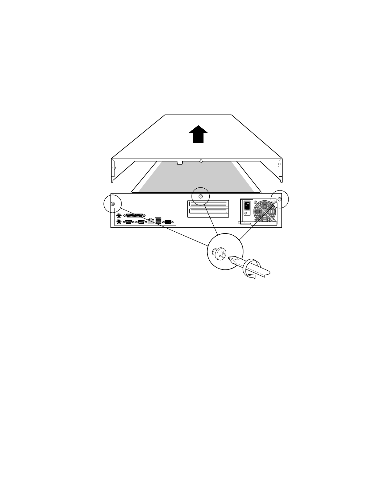
Covers
Opening the Cover
1. Loosen the three screws on the rear of the system.
2. Pull the cover back and remove it from the chassis.
Figure 7. Opening the Cover
Closing the Cover
1. Place the cover on the chassis and slide it forwards as far as possible.
2. Tighten the three screws on the rear of the chassis.
OM09327
Upgrading and Installing Server Components 29
Page 30

Processors
WARNING
If the server has been running, any installed processor and heat sink on
the processor board(s) will be hot. To avoid the possibility of a burn, be
careful when removing or installing server board components that are
located near processors.
CAUTIONS
Processor must be appropriate: You may damage the server if you
install a processor that is inappropriate for your server. Make sure your
server can handle a newer, faster processor (thermal and power
considerations). For exact information about processor interchangeability,
contact your customer service representative or visit the Intel Customer
Support web site:
http://support.intel.com/support/motherboards/server/LB440gx
Heat sink must be appropriate: Depending on your configuratio n, th e
existing processor may have a passive heat sink. If you REPLACE the
processor with a faster one, it must have an active fan heat sink (powered fan
instead of a passive heat sink). If you ADD a second processor, it must have
a fan heat sink. When adding a processor, you must leave the existing one in
the primary connector (closest to the DIMM slots on the server board).
ESD and handling processors: Reduce the risk of electrostatic
discharge (ESD) damage to the processor by doing the following: (1) Touch
the metal chassis before touching the processor or server board. Keep part of
your body in contact with the metal chassis to dissipate the static charge
while handling the processor. (2) Avoid moving around unnecessarily.
30 ISP2150 2U Rack Server Platform Product Guide
Page 31

Installing a Processor
The server supports up to two Intel Pentium II or Pentium III processors (with 100 MHz system
bus). If you are installing two processors, make sure they are the same speed, voltage, and
stepping.
1. Observe the safety and ESD precautions at the beginning of this chapter and the additional
cautions given here.
2. Remove the new processor from its anti-static package and place it on a grounded, static free
surface or conductive foam pad.
3. Attach the small end of the power cable to the fan connector on the S.E.C. cartridge, then attach
the connector (E) to the 3-pin signal prongs (F) on the server board.
A
E
F
C
D
B
OM09315
Figure 8. Installing a Processor
A. Second processor
B. Retention mechanism (right side)
C. Secondary processor slot
D. Off-center notch on secondary slot connector
E. Processor fan 2 connector
F. Processor fan 2 signal prongs
4. Orient the processor so that the heat sink faces the I/O connectors. Slide the processor into the
retention module. Push down firmly, with even pressure on both sides of the top, until the
processor is seated.
5. To lock in the processor, push the latches inward on the retention module until they click into
place. The latches must be secured for proper electrical connection of the processor.
6. After you have installed the processor, you must configure its speed in BIOS set-up.
Upgrading and Installing Server Components 31
Page 32

CAUTION, SINGLE-PROCESSOR CONFIGURATIONS
If you install only one processor in a system, it must go in the primary
connector (closest to the DIMM sockets). With a single-processor
configuration, you must install a termination board and termination latch
assembly (A) in the empty secondary connec tor (B ) to ensu re prope r
operation of your system. A termination board is provided with your system.
A
B
OM09328
Figure 9. Installing a Termination Board
A. Terminator Latch Assembly (TLA)
B. Secondary retention mechanism
Removing a Proces sor
If your server has one processor and you are REPLACING it, leave the termination board intact in
the secondary connector. Remove the processor you want to replace. If your server has two
processors and you are REPLACING one or both, remove the appropriate one(s).
1. Observe the safety and ESD precautions at the beginning of this chapter and the additional
cautions given here. If the processor has a fan heat sink, disconnect the power wire (E in
Figure 8) from the connector on the server board (F in Figure 8).
2. As you work, place boards and processors on a grounded, static free surface or conductive
foam pad.
3. Press the processor latches away from the center of the S.E.C. cartridge (A in Figure 8) to free
them from the retention module (B in Figure 8).
4. Lift the S.E.C. cartridge upward, out of the retention module.
5. Put the processor in a piece of conductive foam and store in an anti-static package.
32 ISP2150 2U Rack Server Platform Product Guide
Page 33

Memory
Installing DIMMs
The server only supports 100 MHz PC/100-compliant SDRAM.
• Install from 32 MB to 2 GB of unbuffered memory, using up to four single or double-banked
DIMMs
Or
• Install from 32 MB to 2 GB of registered memory, using up to four single or double-banked
DIMMs
Installed DIMMs must be the same speed and either all registered or all unbuffered. For a list of
supported memory, call your service representative or visit the Intel Support website:
Http://support.intel.com/support/motherboards/server/l440gx/compat.htm
CAUTION
Use extreme care when installing a DIMM. Applying too much pressure can
damage the socket. DIMMs are keyed and can be inserted in only one way.
Mixing dissimilar metals may cause later memory failures resulting in data
corruption. Only install DIMMs with gold-plated edge connectors in
gold-plated sockets.
To install your memory:
1. Observe the safety and ESD precautions at the beginning of this chapter.
2. Open your server.
3. Holding the DIMM only by its edges, remove it from its anti-static package.
4. Orient the DIMM so that the two notches in the bottom edge of the DIMM align with the keyed
socket.
5. Insert the bottom edge of the DIMM into the socket, and press down firmly on the DIMM until
it seats correctly.
6. Gently push the plastic ejector levers on the socket ends to the upright position.
Upgrading and Installing Server Components 33
Page 34

OM09318
Figure 10. Installing DIMMs
7. Repeat the steps to install each DIMM.
8. Ensure that no cables are protruding from the server chassis and then close the server.
9. Connect all external cables and the power cord to the server.
10. Turn on the monitor and then the server.
Removing DIMMs
CAUTION
Use extreme care when removing a DIMM. Too much pressure can damage
the socket slot. Apply only enough pressure on the plastic ejector levers to
release the DIMM.
1. Observe the safety and ESD precautions at the beginning of this chapter.
2. Open the server.
3. Gently push the plastic ejector levers out and down to eject a DIMM from its socket.
4. Hold the DIMM only by its edges, being careful not to touch its components or gold edge
connectors. Carefully lift it away from the socket, and store it in an antistatic package.
5. Repeat to remove other DIMMs as necessary.
6. Close the server.
7. Connect all external cables and the power cord to the server.
8. Turn on the monitor and then the server.
34 ISP2150 2U Rack Server Platform Product Guide
Page 35

Peripheral Devices
Removing the Diskette Drive
1. Observe the safety and ESD precautions at the beginning of this chapter.
2. Disconnect the power (B) and signal (A) cables from the diskette drive. The connectors are
keyed for ease in reconnecting them to the drive.
A
B
C
Figure 11. Removing the Diskette Drive from the Chassis
A. Signal cable
B. Power cable
C. Screws
OM09316
3. Remove and save the screws (C) that secure the diskette drive carrier to the front of the chassis.
4. Slide the drive carrier out the front of the chassis.
5. Remove and save the screws from the sides of the drive carrier.
6. Pull the drive out of the carrier and place the drive in an anti-static protective wrapper if you
are not reinstalling it.
Upgrading and Installing Server Components 35
Page 36

Re-installing the Diskette Drive
1. Remove the 3.5-inch diskette drive from its protective wrapper, and place it component-side up
on an anti-static surface.
2. Install the drive into the drive carrier and secure it with the screws that you removed.
3. Slide the drive carrier through the front of the chassis.
4. Secure the drive carrier to the front of the chassis with the screws you removed earlier.
5. Connect the signal and power cables to the drive according to the manufacturer’s
specifications.
Installing a Hard Drive
Your server does not include a hard drive. You must purchase them separately and install them.
The server has four hot-swappable hard drive bays.
1. Remove the drive carrier(s) from the drive bays by unclipping the retention lever on the right
side of the handle. Pull the retention lever toward you until the tab end (B) of the lever is free
of the housing slot (A). Pull the drive forward and out of the housing.
2. Remove the hard drive from its wrapper and place it on an anti-static surface.
3. Set any jumpers and/or switches on the drive according to the drive manufacturer’s
instructions.
BA
OM09317
Figure 12. Removing the Hard Drive Carrier from the Chassis
4. Remove and save the four screws (D in Figure 13) from the drive carrier/drive slide track.
36 ISP2150 2U Rack Server Platform Product Guide
Page 37

E
A
B
D
C
OM09323
Figure 13. Attaching the Drive to the Carrier
A. Hard disk drive D. Screws (4)
B. Drive carrier E. Connector end of drive
C. Plastic slide rails (2)
5. Align the drive holes to the holes in the drive carrier slide track (C), insert the screws that you
previously removed, and attach the carrier (B) to the drive (A). Make sure that the connector
end of the drive (E) is facing the back of the carrier and the drive top is facing upward before
inserting the screws.
6. Slide the carrier/drive into the chassis with the retention mechanism extended in the open
position, then push the arm towards the front of the chassis until the lever tab (B) clicks into the
chassis slot (A) indicating that it is closed.
Upgrading and Installing Server Components 37
Page 38

Installing a Slim-line CDROM Drive
Your server does not come with an integrated slim-line CD-ROM drive. You must purchase one
separately and install it.
1. Remove the drive from its protective wrapper, and place it on an anti-static surface.
2. Set any jumpers and/or switches on the drive according to the drive manufacturer’s
instructions.
3. Attach the CD-ROM drive to the CDROM tray using the mounting screws (A) supplied with
the system.
A
OM09348
Figure 14. Attaching a Slim-line CDROM Drive to the CDROM Tray
A. Mounting screws
4. Remove the screws that hold the filler panel to the front of the chassis and slide out the panel.
38 ISP2150 2U Rack Server Platform Product Guide
Page 39

B
C
D
Figure 15. Installing a Slim-line CDROM Drive
A. Signal cable
B. Power cable
C. Screws
D. Retention screw
A
OM09319
5. Slide the slim-line CDROM tray into the CDROM bay. It is recommended that you first
remove the diskette drive in the section “Removing the Diskette Drive”.
6. Connect the CDROM IDE cable (A) and power (B) cables to the connector at the back of the
CD tray.
7. Reinstall the diskette drive in the section “Re-Installing the Diskette Drive”.
8. Insert the recessed retention screws (C) through the access holes in the top of the drive bay
housing.
9. Insert the retention screw (D) on the front of the chassis.
Removing a CDROM Drive
1. Remove the diskette drive housing as outlined in the section “Removing the Diskette Drive”.
2. Remove the three screws holding the drive to the chassis.
3. Disconnect the power and data cables from the drive.
4. Slide the drive tray out of the front of the chassis.
5. Remove the CDROM from the CDROM tray.
6. Place the drive in an anti-static protective wrapper if you are not reinstalling the same drive.
7. Re-install the diskette drive housing as outlined in the section “Installing the Diskette Drive”.
Upgrading and Installing Server Components 39
Page 40

Add-in Cards
Installing Add-in Cards
You can only add two PCI cards to this server. You must use the PCI slots on the riser card. Do
not use any expansion slots on the server board.
1. Remove the expansion slot cover for the slot you wish to use. Remove the thumbscrew (B)
holding the cover retention bracket (A) to the chassis. Remove the bracket from the chassis.
2. Remove the expansion slot cover (C) for the slot you wish to use.
B
A
C
OM09325
Figure 16. Removing the Slot Cover Retention Bracket
A. Slot cover retention bracket
B. Thumbscrew
C. Slot covers
40 ISP2150 2U Rack Server Platform Product Guide
Page 41

3. Remove the add-in board from its protective wrapper. Set jumpers or switches according to the
manufacturer’s instru ctions.
B
Figure 17. Installing an Add-in Card
A. PCI slot
B. Add-in card bracket
A
OM09326
4. Hold board by its top edge or upper corners. Firmly press it into an open expansion slot on the
riser card. The tapered foot of the board-retaining bracket must fit into the mating slot in the
expansion slot frame. Install the board component side DOWN.
✏ NOTE
If you are installing a full-length PCI card, slide the card guide in front of the
fans before installing the card.
5. Align the rounded notch in the retaining bracket (B) with the threaded hole in the frame. The
bracket fits the space that was occupied by the slot cover.
✏ NOTE
If you are installing a full-length PCI card, slide the card guide back into
place. The back edge of the card should be held in place by the rail of the
card guide.
6. Install the cover retention bracket and thumbscrew.
Upgrading and Installing Server Components 41
Page 42
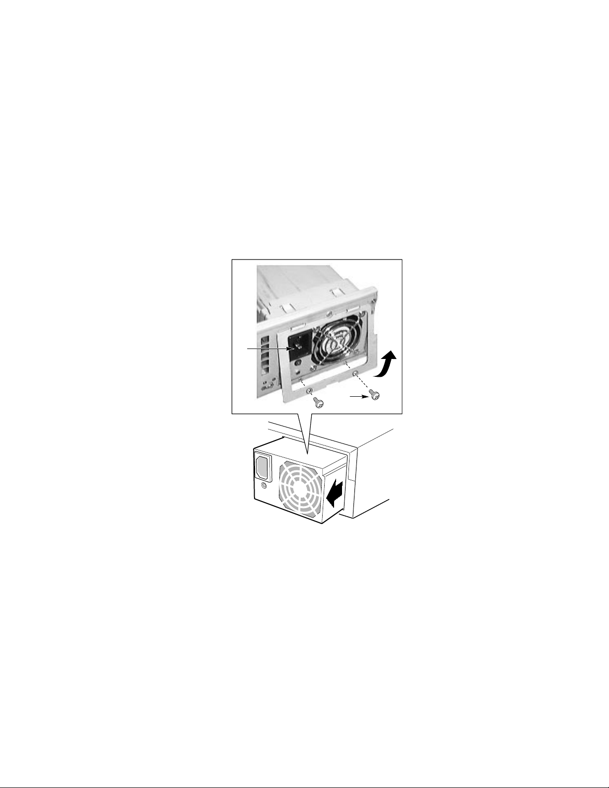
Power Supply
Removing and Re-installing a Power Supply
To replace the power supply:
1. Unplug the power cord from the power source and from the power cord receptacle (A) at the
right rear side of the system.
2. Remove the top cover of the system. Refer to “Opening the Cover” on page 29.
3. Remove and save the two screws (B) from the power supply cover (C).
4. Grasp the bottom edge of the power supply cover and lift it up and away from the power
supply.
5. Grasp the sides of the power supply and slide it forward, out of the chassis.
A
B
Figure 18. Replacing the Power Supply
A. Power cord receptacle
B. Screws
C. Cover
C
OM09324
6. Slide the new power supply into the chassis and make sure it is seated in the chassis connector.
7. Close the power supply cover and re-insert the screws you set aside earlier.
8. Re-connect the power cord to the power cord receptacle and plug the cord back into its power
source.
42 ISP2150 2U Rack Server Platform Product Guide
Page 43

System Mounts
There are two methods for installing the ISP2150, using the fro nt brac ket har dware or optiona lly
using rack rail system.
Installing the Front Bracket and Racking the System
The ISP2150 system comes with mounting bracket hardware that allows you to install it into
cabinets and relay racks. The following procedures describe how to mount the ISP2150 system in
each type of chassis.
Installing the Front Bracket in a Cabinet
1. Attach the left and right front brackets to
the system. Your system comes with left
and right front brackets (A in Figure 19)
and mounting bolts (B in Figure 19) to
attach them to the system. Mount the
brackets to the sides of the system with
the bracket flange flush with the front
panel.
2. Attach the rear support washer to the
system. The system also comes with two
support washers (C in Figure 19). Mount
one on each side towards the rear panel
of the system.
3. Mount the back support bracket to the
cabinet. Left and right rear support
brackets (A and B in Figure 20) also
come with the system. Mount the rear
brackets in the desired position in the
cabinet using the supplied mounting
bolts (C in Figure 20) supplied by the
cabinet manufacture r.
4. Slide the system into the back support
bracket. After attaching the rear
brackets, slide the system into the rack
using the support washers as rollers.
B A C
OM09334
Figure 19. Mounting the Front Brackets
and Support Washers
AC B
OM09336
Figure 20. Mounting the Back Support
Brackets
Upgrading and Installing Server Components 43
Page 44

5. Mount the front bracket to the cabinet.
To complete the installation, bolt the
system’s front brackets to the cabinet
using the mounting bolts (A in Figure
21) supplied by the cabinet manufacturer.
Figure 21. Mounting the Front Brackets
to the Cabinet Chassis
Installing the Front Bracket in a Center-Mount, Relay Rack
1. Attach the left and right front brackets to
the system. Your system comes with left
and right front brackets (A in Figure 22)
and mounting bolts (B in Figure 22) to
attach them to the system. Mount the
brackets mid-way down the sides of the
system as shown in the figure.
AA
OM09346
✏ NOTE
You can also mount the bracket
so that the flange is flush with
the front panel.
2. Mount the bracket to the center channel
of the relay rack. To complete the
installation, bolt the system’s front
brackets to the cabinet using the
mounting bolts (A in Figure 23) supplied
by the cabinet manufacturer.
BA
OM09335
Figure 22. Mounting the Front Brackets
Midway Along the System
A
OM09347
Figure 23. Mounting the Front Brackets
to the Relay Rack
A
44 ISP2150 2U Rack Server Platform Product Guide
Page 45

Installing the Rail Rack and Rack ing the System (Optional Accessory)
The rail kit that comes with your system allows you to install it into a four-post, network server
cabinet (e.g. APC Netshelter). If the cabinet is not of this general type, you will have to purchase a
separate rail kit that is specific to your cabinet.
Follow these steps to install the rail kit and place your system into the cabinet.
1. Assemble tools and miscellaneous parts.
You will need a Phillips screwdriver and
assorted lock washers and nuts.
Remove the inside piece (C in Figure 24)
2.
from both sides of the rail system. To
remove an inside piece of the rail system,
slide the part as far out as you can. This
action reveals a brass colored finger tab
(D in Figure 24) that when depressed
allows you to completely separate the
inside rail piece from the outer (A in
Figure 24) and middle (B in Figure 24)
rail pieces.
3. Align each inside rail (A in Figure 25) to
a side of the chassis. Be sure that the flat
end of the inside rail is toward the front
of the chassis and that the brass colored
finger tab (D in Figure 25) is facing
outward. With the holes in the chassis
(C in Figure 25) aligned with the holes in
the rail, fasten the rail using the larges t
screws (B in Figure 25) supplied with the
rail kit.
D
DD
A B C
OM09132
Figure 24. Rail System
C
D
A
B
OM09133
Figure 25. Aligning Rail to Chassis
Upgrading and Installing Server Components 45
Page 46

4. Here is a combination side and rear view
(Figure 26) of the chassis after the right
inside rail has been attached.
Figure 26. Chassis Rear and Side View
5. Locate the front and rear rail brackets
for one side of the rail kit. One pair (A
and B in Figure 27) exists for each side
of the cabinet rack.
6. Attach all four rail brackets to the
cabinet rack. Be sure that the sharper
angled side of each bracket is facing up
(C in Figure 28). Use eight mounting
screws (D in Figure 28) provided by the
manufacturer of the cabinet rack. In the
illustration to the right, the left photo (A
in Figure 28) shows the left-front
bracket attached to the cabinet, while
the right photo (B in Figure 28) shows
the left-rear bracket. (The photo shows
the rails inside the brackets. You should
not have the rails attached inside the
brackets yet.)
A
Figure 27. Rail Brackets
C C
D
A
Figure 28. Attaching Rail Brackets
to Cabinet Rack
B
OM09145
D
B
OM09142
46 ISP2150 2U Rack Server Platform Product Guide
Page 47

7. Attach the side rail system’s outer
pieces (total of two) to the rail brackets
you installed in step six. To attach the
front part of an outer piece to a rail
bracket, you must reveal the access hole
(A in Figure 29) by sliding the
innermost piece toward the back. Once
you see the access hole, align it with the
slot in the rail bracket such that you can
secure the bolt. Do not tighten the nut
and bolt until you have aligned the rear
portion of the rail system (see the next
step).
8. To attach the rear part of the rail system
to the rear rail bracket (A in Figure 30),
slide the rail system within the rail
brackets such that you can place a bolt
through the rail’s hole (B in Figu re 30)
and into the rail bracket’s slot. Loosely
tighten the bolt and nut. You should be
able to slide the entire rail system back
and forth in the rail brackets. When you
have centered the rails in the bracket,
tighten the fastening bolts and nuts.
A
B
Figure 29. Attaching Outer Pieces
to Rail Brackets
C
A
B
Figure 30. Attaching Rail System
to Rear Rail Bracket
C
OM09138
OM09144
Upgrading and Installing Server Components 47
Page 48

9. Extend the right and left rails (A in
Figure 31) so they fully extend in front of
the cabinet rack. The rail system is now
ready to receive the chassis.
A
Figure 31. Extending the Rails
A
OM09141
10. Lift the chassis with its front facing you
and carefully guide the inner rail (A in
Figure 32), which is mounted to the
chassis system, into the outer pieces (B
in Figure 32) you attached in previous
steps. Gently move the system evenly
towards the rear of the cabinet. Be sure
to depress the brass colored finger tabs
located in the center of each inner side
rail piece as you slide the chassis back.
11. With the chassis fully inserted into the
cabinet rack, you can easily access both
the front and rear of the system. The
photo in Figure 33 shows the system
from the rear fully inserted into the
cabinet.
A
Figure 32. Guiding Chassis into the Rack
Figure 33. Chassis Mounted into the Rack
B
OM09143
48 ISP2150 2U Rack Server Platform Product Guide
Page 49

Replacing the Back up Battery
The lithium battery on the server board powers the real time clock (RTC) for up to 10 years in the
absence of power. When the battery starts to weaken, it loses voltage, and the server settings stored
in CMOS RAM in the RTC (for example, the date and time) may be wrong. Contact your customer
service representative or dealer for a list of approved devices.
WARNING
Danger of explosion if battery is incorrectly replaced. Replace only with
the same or equivalent type recommended by the equipment
manufacturer. Discard used batteries according to manufacturer’s
instructions.
ADVARSEL!
Lithiumbatteri - Eksplosionsfare ved fejlagtig håndtering. Udskiftning
må kun ske med batteri af samme fabrikat og type. Levér det brugte
batteri tilbage til leverandøren.
ADVARSEL
Lithiumbatteri - Eksplosjonsfare. Ved utskifting benyttes kun batteri
som anbefalt av apparatfabrikanten. Brukt batteri returneres
apparatleverandøren.
VARNING
Explosionsfara vid felaktigt batteribyte. Använd samma batterityp eller
en ekvivalent typ som rekommenderas av apparattillverkaren. Kassera
använt batteri enligt fabrikantens instruktion.
VAROITUS
Paristo voi räjähtää, jos se on virheellisesti asennettu. Vaihda paristo
ainoastaan laitevalmistajan suosittelemaan tyyppiin. Hävitä käytetty
paristo valmistajan ohjeiden mukaisesti.
Upgrading and Installing Server Components 49
Page 50

B
A
C
OM07843
Figure 34. Replacing the Lithium Battery
1. Observe the safety and ESD precautions at the beginning of this chapter.
2. Open the chassis.
3. Insert the tip of a small flat bladed screwdriver, or equivalent, under the tab in the plastic
retainer.
4. Gently push down on the screwdriver to lift the battery.
5. Remove the battery from its socket.
6. Dispose of the battery according to local ordinance.
7. Remove the new lithium battery from its package, and, being careful to observe the correct
polarity, insert it in the battery socket.
8. Reinstall the plastic retainer on the lithium battery socket.
9. Close the chassis.
10. Run the SSU to restore the configuration settings to the RTC.
50 ISP2150 2U Rack Server Platform Product Guide
Page 51

3 Configuration Software and Utilities
This chapter describes the Power On Self Test (POST) and server configuration utilities. The table
below briefly describes the utilities.
Table 4. Configuration Utilities
Utility Description and brief procedure Page
BIOS Setup If the system does not have a diskette drive, or the drive is disabled or
mis-configured, use Setup to enable it.
Or, you can move the CMOS jumper on the server board from the
default setting (Protect CMOS memory) to the Clear setting; this will
allow most server configurations to boot. For the procedure to do this,
see the section “CMOS Jumper” in Chapter 5 in this manual. Then run
the SSU to configure the server.
System Setup Utility
(SSU)
EMP Console Use to access and monitor the server remotely. 79
FRUSDR Load Utility Use to update the Field Replacement Unit (FRU), Sensor Data Record
BIOS Update Utility Use to update the BIOS or recover from a corrupted BIOS update. 95
Firmware Update Utility Use to update BMC and HSC flash ROM. 98
Using the Adaptec SCSI
Utility
Use for extended system configuration of onboard resources and addin boards, and for viewing the system event log, setting boot device
priority, or setting syste m security options.
The SSU may be run from either the Server Configuration CD or from
a DOS-bootable diskette.
Information entered via the SSU overrides information entered via
BIOS Setup.
(SDR), and Desktop Management Interface (DMI) flash components.
Use to configure or view the settings of the SCSI host adapters and
onboard SCSI devices in the server.
53
67
92
99
Hot Keys
Use the keyboard’s numeric pad to enter numbers and symbols.
Table 5. Hot Keys
To do this: Press these keys
Clear memory and reload the operating
systemthis is a system reset.
Secure your system immediately. <Ct rl+Alt>+hotkey (Set your hot key combination with the SSU or
<Ctrl+Alt+Del>
Setup.)
51
Page 52

Power On Self Test (POST)
Each time you turn on the system, POST starts running. POST checks the server board, processor,
memory, keyboard, and most installed peripheral devices. During the memory test, POST displays
the amount of memory that it is able to access and test. The length of time needed to test memory
depends on the amount of memory installed. POST is stored in flash memory.
1. Turn on your video monitor and server. After a few seconds POST begins to run.
2. After the memory test, these screen prompts and messages appear until POST completes or
until the user presses F2:
Press <F2> key if you want to run SETUP
Keyboard.....Detected
Mouse........Detected
3. During peripheral device detection, the following message appears:
Press <Ctrl><A> to enter SCSI Utility
4. Press <Ctrl+A> if there are SCSI devices installed. When the utility opens, follow the
displayed instructions to configure the onboard SCSI host adapter settings and to run the
SCSI utilities. Also see “Using the Adaptec SCSI Utility” on page 99. If you do not enter the
SCSI utility, the boot process continues.
5. Press <Esc> during POST to pop up a boot menu when POST finishes. From this menu you
can choose the boot device or enter BIOS Setup.
After POST completes, the system beeps once.
What appears on the screen after this depends on whether you have an operating system loaded and
if so, which one.
If the system halts before POST completes running, it emits a beep code indicating a fatal system
error that requires immediate attention. If POST can display a message on the video display screen,
it causes the speaker to beep twice as the message appears.
Note the screen display and write down the beep code you hear; this information is useful for your
service representative. For a listing of beep codes and error messages that POST can generate, see
the “Solving Problems” chapter in this manual.
52 ISP2150 2U Rack Server Platform Product Guide
Page 53

Using BIOS Setup
This section describes the BIOS Setup options. Use Setup to change the server configuration. You
can run Setup with or without an operating system being present. Setup stores most of the
configuration values in battery backed CMOS; the rest of the values are stored in flash memory.
The values take effect when you boot the server. POST uses these values to configure the
hardware; if the values and the actual hardware do not agree, POST generates an error message.
You must then run Setup to specify the correct configuration.
Run Setup: You may run Setup to modify such server board feature as:
• Select diskette drive
• Select parallel port
• Select serial port
• Set time/date (to be stored in RTC)
• Configure IDE hard drive
• Specify boot device sequence
• Enable SCSI BIOS
• View processor speed
Run SSU, not Setup: You must run the SSU instead of Setup to do the following:
• Add or remove any ISA board that is not Plug and Play-compatible
• Enter or change information about a board
• Alter server resources (such as interrupts, memory addresses, I/O assignments) to user selected
choices instead of choices selected by the BIOS resource manager
Record Your Setup Settings
If the values ever need to be restored (after a CMOS clear, for example), you must run Setup again.
Referring to the worksheets could make your task easier.
If You Cannot Access Setup
If the diskette drive is mis-configured so that you cannot access it to run a utility from a diskette,
you may need to clear CMOS memory. You will need to open the server, change a jumper setting,
use Setup to check and set diskette drive options, and change the jumper back. For a step-by-step
procedure, see Chapter 5, under the heading, “CMOS Jumper.”
Configuration Software and Utilities 53
Page 54

Starting Setup
You can enter Setup after power on or reset by pressing F2. After booting, you will see the
following prompt:
Press <F2> to enter SETUP
If CMOS/NVRAM has been corrupted, you will see other prompts:
Warning: cmos checksum invalid
Error 0271: check date and time settings
In this condition, the BIOS will load default values for CMOS and attempt to boot.
Setup Menus
To: Press
Get general help <F1> or <Alt+H>
Move between menus
Go to the previous item
Go to the next Item
Change the value of an item + or -, F5, F6, space
Select an item or display a submenu <Enter> or <Alt+X>
Leave a submenu or exit Setup <Esc>
Reset to Setup defaults <F9>
Save and exit Setup <F10>
← →
↑
↓
When you see this: What it means
On screen, an option is shown but you
cannot select it or move to that field.
On screen, the phrase Press Enter
appears next to the option.
You cannot change or configure the option in that menu screen.
Either the option is auto-configured or auto-detected, or you
must use a different Setup screen, or you must use the SSU.
Press <Enter> to display a submenu that is either a separate full
screen menu or a popup menu with one or more choices.
The rest of this section lists the features that display onscreen after you press <F2> to enter Setup.
Not all of the option choices are described, because (1) a few are not user selectable but are
displayed for your information, and (2) many of the choices are relatively self explanatory.
54 ISP2150 2U Rack Server Platform Product Guide
Page 55

Main Menu
You can make the following selections on the Main Menu itself. Use the submenus for other
selections.
Feature Choices Description
System Time HH:MM:SS Sets the system time
System Date MM/DD/YYYY Sets the system date
Legacy Diskette A: Disabled
360KB
1.2 MB
720KB
1.44/1.25 MB
2.88 MB
Legacy Diskette B: Disabled
360KB
1.2 MB
720KB
1.44/1.25 MB
2.88 MB
Primary IDE Master Enters submenu
Primary IDE Slave Enters submenu
Secondary IDE Master Enters submenu
Secondary IDE Slave Enters submenu
Keyboard Features Enters submenu
Processor Settings Enters submenu
Language English (US)
Français
Español
Deutsch
Italiano
Note: Bold type indicates the default choice.
Selects the diskette type
Selects which language BIOS displays
Configuration Software and Utilities 55
Page 56

Primary/Secondary IDE Master and Slave Submenu
Feature Choices Description
Type Auto
None
CD-ROM
IDE Removable
ATAPI Removable
User
CHS Format
Cylinders 0 to 65535 Number of Cylinders on Drive.
Heads 1 to 16 Number of read/write heads on drive.
Sectors 0 to 63 Number of sectors per track.
Maximum
Capacity
LBA Format
Total Sectors N/A This field is informational only.
Maximum
Capacity
Multi-Sector
Transfer
LBA Mode
Control
32 Bit I/O Disabled
Transfer Mode Standard
Ultra DMA
Mode
Note: Bold type indicates the default choice.
N/A
N/A This field is informational only.
Disabled
2, 4, 8, or 16
sectors
Disabled
Enabled
Enabled
Fast PIO 1
Fast PIO 2
Fast PIO 3
Fast PIO 4
FPIO 3 / DMA 1
FPIO 4 / DMA 2
Disabled
Mode 0
Mode 1
Mode 2
Auto forces the server to attempt autodetection of the drive type.
None informs the server to ignore this drive.
CD ROM allows the manual entry of some fields described below.
IDE Removable allows the manual entry of some fields described
below.
ATAPI Removable allows the manual entry of some fields
described below.
User allows the manual entry of all fields described below.
This field is changeable only for Type User.
This field is available only for Type User.
This field is available only for Type User.
Computed size of drive from cylinders, heads, and sectors
entered. This field is informational only.
Determines the number of sectors per block for multi-sector
transfers.
This field is informational only for Type Auto.
Enabling LBA causes logical block addressing to be used in place
of cylinders, heads, and sectors.
This field is informational only for Type Auto.
Enabling allows 32 bit IDE data transfers.
Selects the method for moving data to and from the drive.
This field is informational only for Type Auto.
Selects the Ultra DMA mode used for moving data to/from
the drive.
56 ISP2150 2U Rack Server Platform Product Guide
Page 57

Keyboard Submenu
Feature Choices Description
Num Lock On
Off
Key Click Disabled
Enabled
Keyboard auto-repeat rate 30/sec
26.7/sec
21.8/sec
18.5/sec
13.3/sec
10/sec
6/sec
2/sec
Keyboard auto-repeat delay 1/4 sec
1/2 sec
3/4 sec
1 sec
Note: Bold type indicates the default choice.
Processor Settings Submenu
Feature Choices Description
CPU Speed Setting 350 MHz
400 MHz
450 MHz
500 MHz
550 MHz
600 MHz
650 MHz
667 MHz
700 MHz
CPU POST Speed Settings N/A This field is informational only.
Processor Retest Yes
No
Selects the power on state for Num Lock.
Enables or disables the audible key click.
Sets the numbers of time per second a key will repeat while
it is held down.
Sets the delay before a key starts to repeat when it is held
down.
Sets the speed for the installed processor(s). This feature is
not active (that is, it is grayed out) if the CPU speed setting
is locked.
CAUTION
Attempting to set this higher than the proper speed
for the installed processor(s) may cause damage to
the processor(s) or prevent the server from booting
until a CMOS clear is preformed.
Yes tells BIOS to clear the historical processor status and
retest all processors on the next boot. BIOS automatically
resets to No in next boot.
Processor serial number Enabled
Disabled
Memory Cache Enabled
Disabled
Processor 1 Stepping ID N/A This field is informational only.
Processor 1 L2 Cache Size N/A This field is informational only.
Processor 2 Stepping ID N/A This field is informational only.
Processor 2 L2 Cache Size N/A This field is informational only.
Note: Bold type indicates the default choice.
Configuration Software and Utilities 57
Controls the detection of the processor’s serial number.
Enables processor cache.
Page 58

Advanced Menu
You can make the following selections on the Advanced Menu itself. Use the submenus for the
three other selections that appear on the Advanced Menu.
Feature Choices Description
Installed OS Other
Plug-N-Play
Reset Configuration Data No
Yes
PCI Configuration Enters submenu.
Integrated Peripherals
Configuration
Advanced Chipset Control Enters submenu.
Use Multipro cessor
Specification
Large Disk Access Mode CHS
Delay on Option ROMs Disabled
Note: Bold type indicates the default choice.
1.1
1.4
LBA
Enabled
Select Plug-N-Play if you are booting a Plug and Play
capable operating system.
Select Yes if you want to clear the server configuration
data during next boot. System automatically resets to No
in next boot.
Enters submenu.
Selects the version of multiprocessor specification to use.
Some operating systems do not support version 1.4.
Select CHS if your OS is DOS. A large disk has more than
1024 cylinders, more than 16 heads, or more than
63 tracks per sect or.
Forces a short delay at the end of each Option ROM scan.
PCI Configuration Submenu
The PCI Configuration Menu contains selections that access other submenus.
PCI Device, Embedded SCSI Submenu
Feature Choices Description
Option ROM Scan Enabled
Disabled
Enable Master Enabled
Disabled
Latency Timer Default
0020h
0040h
0060h
0080h
00A0h
00C0h
00E0h
Note: Bold type indicates the default choice.
Enables option ROM scan of the onboard SCSI chip.
There are 2 SCSI channels that are controlled by the same
option ROM.
Enabled selects the device as a PCI bus master.
Minimum guaranteed time, in units of PCI bus clocks, that
a device may be master on a PCI bus.
CAUTION
Do not change this setting unless you fully
understand the priority of this device on the
PCI bus.
58 ISP2150 2U Rack Server Platform Product Guide
Page 59

PCI Device, Slot 1 - Slot 6 Submenus
Feature Choices Description
Enable Master Enabled
Disabled
Latency Timer Default
020h
040h
060h
080h
0A0h
0C0h
0E0h
Note: Bold type indicates the default choice.
Enables selected device as a PCI bus master.
Minimum guaranteed time, in units of PCI bus clocks, that
a device may be master on a PCI bus.
CAUTION
Do not change this setting unless you fully
understand the priority of this device on the
PCI bus.
Integrated Peripheral Configuration Submenu
Feature Choices Description
COM 1 Disabled
Enabled
Auto
OS Controlled
Base I/O Address 3F8
2F8
3E8
2E8
Interrupt IRQ 3
IRQ 4
COM 2 Disabled
Enabled
Auto
OS Controlled
Base I/O Address 3F8
2F8
3E8
2E8
Interrupt IRQ 3
IRQ 4
Parallel Port Disabled
Enabled
Auto
OS Controlled
Mode Output only
Bi-directional
EPP
ECP
Base I/O Address 378
278
Auto forces BIOS to configure the port.
OS Controlled forces the OS to configure the port.
Selects the base I/O address for COM1.
Selects the IRQ for COM1.
Auto forces BIOS to configure the port.
OS configures the port.
Selects the base I/O address for COM2.
Selects the IRQ for COM2.
Auto forces BIOS to configure the port.
OS configures the port.
Selects parallel port mode.
Selects the base I/O address for LPT port.
continued
Configuration Software and Utilities 59
Page 60

Integrated Peripheral Configuration Submenu (continued)
Feature Choices Description
Interrupt IRQ 5
IRQ 7
DMA channel DMA 1
DMA 3
Floppy disk controller Disabled
Enabled
Note: Bold type indicates the default choice.
Selects the IRQ for LPT port.
Selects the DMA for LPT port (only used for ECP mode).
Enables onboard diskette controller.
Advanced Chipset Control
Feature Choices Description
640-768K Memory
Region
Delayed Transaction Enabled
Passive Release Enabled
Note: Bold type indicates the default choice.
Enabled
Disabled
Disabled
Disabled
Enabled forwards ISA Master and DMA cycles to th e
PCI bus. Disabled forwards these cycles to memory.
Enables the delayed transaction mechanism when the
PIIX4e is the target of a PCI transaction.
Enables the passive release mechanism on the
PHOLD# signal when the PIIX4 is a PCI Master.
60 ISP2150 2U Rack Server Platform Product Guide
Page 61

Security Menu
You can make the following selections on the Security Menu itself. Enabling the Supervisor
Password field requires a password for entering Setup. The passwords are not case-sensitive.
Feature Choices Description
User Password is Clear
Set
Supervisor Password is Clear
Set
Set User Password Press Enter When the <Enter> key is pressed, you are prompted for a
Set Supervisor Password Press Enter When the <Enter> key is pressed, you are prompted for a
Password on Boot Disabled
Enabled
Fixed Disk Boot Sector Normal
Write
Protect
Secure Mode Timer 1 min
2 min
5 min
10 min
20 min
1 hr
2 hr
Secure Mode Hot Key
(Ctrl-Alt- )
Secure Mode Boot Disabled
Video Blanking Disabled
Floppy Write Protect Disabled
Front Panel Lockout Disabled
Note: Bold type indicates the default choice.
[0-9- ]
[A, B, ..., Z]
Enabled
Enabled
Enabled
Enabled
Status only; user cannot modify. Once set, this can be disabled
by setting it to a null string, or by clearing password jumper on
server board.
Status only; user cannot modify.
password; press ESC key to abort. Once set, this can be cleared
by setting it to a null string, or by clearing password jumper on
server board (see Server Board Jumpers in Chapter 5).
password; press ESC key to abort. Once set, this can be cleared
by setting it to a null string, or by clearing password jumper on
server board (see Server Board Jumpers in Chapter 5).
Requires password entry before boot. System will remain in
secure mode until password is entered. Password on Boot takes
precedence over Secure Mode Boot.
Write protects boot sector on hard disk to protect against viruses.
Period of key/PS/2 mouse inactivity specified for secure mode to
activate. A password is required for secure mode to function.
Cannot be enabled unless at least one password is enabled.
Key assigned to start the Quicklock feature. Cannot be enabled
unless user password is enabled.
System will boot in secure mode. You must enter a password to
unlock the system. Cannot be enabled unless user password is
enabled.
Blank video when secure mode is activated. You must enter a
password to unlock the system. Cannot be enabled unless user
password is enabled.
When secure mode is activated, the diskette drive is write
protected. You must enter a password to disable. Cannot be
enabled unless user password is enabled.
When secure mode is activated, the reset and power switches are
locked. You must enter a password to unlock the system.
Cannot be enabled unless user password is enabled.
Configuration Software and Utilities 61
Page 62

Server Menu
You can make the following selections on the Server Menu itself.
Feature Choices Description
System
Management
Console Redirection Enters submenu.
PEP Management Enters submenu.
Enable Sleep Button Disabled
Enabled
PCI IRQs to IOAPIC mappings
Processor Retest Yes
Disabled
Enabled
No
Enters submenu.
Enables optional ACPI support for the sleep button.
Enabled - BIOS can describe all 24 IO APIC pins in the
MP table for PCI interrupts. Not all MP operating
systems and drivers can understand this description of
the interrupts in the MP table.
Disabled - BIOS will only use 16 IO APIC pins in the
MP table for PCI interrupts. All PCI interrupts are routed
to a standard ISA IRQ pins on IO APIC. All operating
systems will work with standard ISA IRQ entries.
Yes tells BIOS to clear the historical processor status
and retest all processors on the next boot. BIOS
automatically resets to No in next boot.
Assert NMI on
SERR
Note: Bold type indicates the default choice.
Disabled
Enabled
System Management Submenu
Feature Choices Description
Server Management
Info
System Event
Logging
Clear Event Log No
EMP Password
switch
EMP Password [A..Z, 0..9] This field only shows up when the EMP password switch
EMP Escape
sequence
Disabled
Enabled
Yes
Disabled
Enabled
+++ Sets the escape sequence for the modem being used for
Enabled generates an NMI on SERR.
Enters submenu.
When enabled, system events will be logged by BIOS and
BMC in system event log.
Yes clears the system event log (SEL) in BMC. BIOS
automatically resets to NO for next boot.
Sets the EMP password.
is enabled. Entering a password and pressing return will
send the password immediately to the BMC. If a beep is
heard the password was not accepted. If no password is
entered, anyone has access to the server through the
EMP Console.
EMP. This will force the modem to command mode. This
is only used if the EMP direct connect/modem mode is set
to modem.
continued
62 ISP2150 2U Rack Server Platform Product Guide
Page 63

System Management Submenu (continued)
Feature Choices Description
EMP Hang-up Line
String
Modem Init String AT&F0S0=1S14=0&D Sets the initialization string for the modem being used for
High Modem Init
String
EMP Access Mode Pre-boot Only
EMP Restricted
Mode Access
EMP Direct
Connect/Modem
Mode
Note: Bold type indicates the default choice.
ATH Sets the Hang-up Line Sequence for the modem being
0 This is a continuation of the Modem Init String. When
Always Active
Disabled
Disabled
Enabled
Direct Connect
Modem Mode
used for EMP. Used in EMP modem mode.
EMP. Used in EMP modem mode.
This field is only 16 characters long. The High Modem Init
String field is a continuation of the Modem Init string so
you can enter in another 4 characters.
16 characters are typed into the Modem Init String field,
this field will appear to allow another 4 characters to be
typed in.
Pre-boot Only - EMP is only enabled during power down
through end of POST. COM2 is returned to system use at
the end of Post when operating system boots.
Always Active - EMP is always enabled. COM2 cannot be
used by operating system. It is now dedicated for EMP
use.
Disabled - EMP is disabled. COM2 is always available for
system use by console redirection or operating system.
If set to Enabled, Power on/off and Reset server controls
via EMP are no longer available.
Sets how EMP connects to the server. Direct Connect
means a null modem serial cable directly connects COM2
connector port to the EMP console machine.
Modem mode indicates that a modem is connected on
COM2 for EMP use.
Server Management Information Submenu
Items on this menu are set when the server board is manufactured and cannot normally be changed.
The last two items refer to the firmware level of the BMC on the server board and HSC (Hot Swap
Controller) from the Astor II server chassis. If circumstances require a change in the LB440GX
server board’s firmware, specific direction will be provided by Intel Customer Support.
Feature Choices Description
Board Part Number N/A Information field only
Board Serial Number N/A Information field only
System Part Number N/A Information field only
System Serial Number N/A Information field only
Chassis Part Number N/A Information field only
Chassis Serial Number N/A Information field only
BMC Revision N/A Information field only
Primary HSBP Revision N/A Information field only
Note: Bold type indicates the default choice.
Configuration Software and Utilities 63
Page 64

Console Redirection Submenu
Feature Choices Description
COM Port Address Disabled
3F8
2F8
3E8
IRQ # N/A This field is informational only.
Baud Rate 9600
19.2k
38.4k
115.2k
Flow Control No Flow Control
CTS/RTS
XON/XOFF
CTS/RTS + CD
Note: Bold type indicates the default choice.
When enabled, console redirection uses the I/O port specified.
3F8 - typically is COM1
2F8 - typically is COM2
All keyboard/mouse and video will be directed to this port. This
is designed to be used only under DOS in text mode.
When console redirection is enabled, specifies the baud rate to
be used.
None disallows flow control.
CTS/RTS is hardware-flow control.
XON/XOFF is software-flow control.
CTS/RTS +CD is hardware plus carrier-detect flow control.
PEP Management Submenu
Verify in BIOS Setup of your server board whether or not your system BIOS includes PEP. If not,
when it becomes available, you can download it from the Intel Customer Support web site:
http://support.intel.com/support/motherboards/server/LB440gx
Feature Choices Description
PEP Filter Events Enters submenu.
PEP Enable Disable
Enable
PEP Blackout
Period
PEP Page String Sets the string used to page you. Generally this is the
17-32 This is a continuation of the PEP Page String Field. When
33-48 This is a continuation of the PEP Page String Field. When
49-64 This is a continuation of the PEP Page String Field. When
Send Test Page Press Enter
Note: Bold type indicates the default choice.
[0…9] Sets the amount of time between pages in minutes. Valid
Send Test Page Now
Enables Platform Event Paging.
range is from 0 to 255. A value of 0 indicates no blackout
period.
attention command for your modem, followed by the number of
your paging service, followed by the message you want to
appear on your pager, followed by a modem hang-up
command. Use commas for 1second pauses. This field is
only 16 characters long. The 17-32, 33-48, and 49-64 fields
are a continuation of the PEP Page String Field so you can
enter in another 48 characters for 64 characters total.
16 characters are typed into the Modem Init String field, this
field will appear to allow another 16 characters to be typed in.
16 characters are typed into the Block #2 field, this field will
appear to allow another 16 characters to be typed in.
16 characters are typed into the Block #3 field, this field will
appear to allow another 16 characters to be typed in.
To send a test page, select "Send Test Page Now" from the
popup menu.
64 ISP2150 2U Rack Server Platform Product Guide
Page 65

PEP Filter Submenu
This submenu allows you to set which events or error conditions cause the system to page you.
Feature Choices Description
PEF Enable Disable
Enable
Temperature Sensor Disable
Enable
Voltage Sensor Disable
Enable
Enables the Platform Event Filtering. If this is enabled, and one of
the events you enable below occurs, the server will page you
using the Page String information.
Temperature out of range notification.
Voltage out of range notification.
Fan Sensor Disable
Chassis Sensor Disable
Power Supply Sensor Disable
BIOS (SMI Handler) Disable
BIOS POST Error Disable
FRB Sensor Disable
Fatal NMI Disable
Watchdog Timer Reset Disable
System Restart Disable
Note: Bold type indicates the default choice.
Boot Menu
Fan failure notification.
Enable
Chassis intrusion notification.
Enable
Power supply fault notification.
Enable
Uncorrectable ECC memory error notification.
Enable
POST error code notification.
Enable
FRB failure notification.
Enable
Fatal NMI notification.
Enable
Watchdog timer reset/power down/power cycle notificatio n.
Enable
System reboot notification.
Enable
You can make the following selections on the Boot Menu itself.
Feature Choices Description
Boot-time Diagnostic
Screen
Configuration Software and Utilities 65
Disabled
Enabled
Enables or disables the diagnostic screen during system boot
operations. This screen is alphanumeric text that displays on
the monitor during a boot operation to report status about
such things as the boot memory test, the number & type of
processors, and the disk drives in the system.
When it is disabled, an image is displayed with a bar across
the top of the screen to indicate boot progress instead of the
detailed status information.
continued
Page 66

Boot Menu (continued)
Feature Choices Description
Extended RAM Step 1 MB
1 KB
Every location
No memory test
BIOS Boot Spec
Support
Boot Device Priority Enters submenu.
Hard Drive Enters submenu.
Removable Devices Enters submenu.
Note: Bold type indicates the default choice.
Limited
Disabled
Sets extended memory test to verify once every KB, every
MB, every location, or not at all (no test).
The limited choice may be required if more than eight drives
are installed in certain configurations.
Boot Device Priority
Use the up or down arrow keys to select a device; then press the <+> or <-> keys to move the
device higher or lower in the boot priority list.
Boot Priority Device Description
1. Removable Devices Attempts to boot from a removable media device.
2. Diskette Drive Attempts to boot from a diskette drive.
3. Hard Drive Attempts to boot from a hard drive device.
4. ATAPI CD-ROM Drive Attempts to boot from an ATAPI CD-ROM drive.
5. LANDesk (R) Service Agent II Attempts to boot from the local area network.
Hard Drive
For options on this menu, use the up or down arrow keys to select a device; then press the <+> or
<-> keys to move the device higher or lower in the boot priority list.
Option Description
1. Hard Drive #1 (or actual drive string) IDE drives will have a suffix attached to the drive ID string.
PM - hard drive on Primary Master Channel
PS - hard drive on Primary Slave Channel
SM - hard drive on Secondary Master Channel
SS - hard drive on Secondary Slave Channel
SCSI CD-ROMs will be displayed here because the onboard
SCSI BIOS treats CD-ROMs as hard drives.
SCSI ZIP or removable drives will also appear here.
Removable IDE ZIP drives will only show up if the removable
media is formatted as a hard drive.
2. Other Bootable Device Covers all the boot devices that are not reported to the system
BIOS through the BIOS boot specification mechanism. This
includes all PCI cards that are not BIOS boot compliant (legacy)
as well as ISA cards that are not PnP compliant. ISA legacy
cards will boot first before non BIOS boot compliant PCI cards
(in scan order from lowest slot to highest).
66 ISP2150 2U Rack Server Platform Product Guide
Page 67

Removable Devices
For options on this menu, use the up or down arrow keys to select a device, then press the <+> or
<-> keys to move the device higher or lower in the boot priority list.
Option Description
1. Legacy Floppy Drive Refers to the onboard 3.5” floppy drive.
Removable IDE media may also show up here if the removable media
was formatted in floppy emulation.
Exit Menu
You can make the following selections on the Exit Menu. Select an option using the up or down
arrow keys; then press <Enter> to execute the option. Pressing <Esc> does not exit this menu.
You must select one of the items from the menu or menu bar to exit.
Choices Description
Exit Saving Changes Exits after writing all modified Setup item values to NVRAM.
Exit Discarding Changes Exits leaving NVRAM unmodified.
Load Setup Defaults Loads values of all Setup items from previously saved custom defaults.
Load Custom Defaults Loads default values for all Setup items.
Save Custom Defaults Saves present Setup values to custom defaults.
Discard Changes Reads previous values of all Setup items from NVRAM.
Save Changes Writes all Setup item values to NVRAM.
Using the System Setup Utility
The SSU provides a graphical user interface (GUI) over an extensible framework for server
configuration. For the ISP2150 system, the SSU framework supports the following functions and
capabilities:
• assigns resources to baseboard devices and add-in cards prior to loading the operat ing
system (OS)
• allows you to specify boot device order and system security options
• permits viewing and clearing of the system’s system event log
• allows troubleshooting of the server when the OS is not operational
• provides a system level view of the server’s I/O devices
Configuration Software and Utilities 67
Page 68

When to Run the System Setup Utility
The SSU is a DOS-based utility that supports extended system configuration operations for onboard
resources and add-in boards. You can also view the system event log and to set system boot and
security options. Use the SSU when you need to:
• add and remove boards affecting the assignment of resources (ports, memory, IRQs, DMA)
• modify the server’s boot device order or security settings
• change the server configuration settings
• save the server configuration
• view or clear the system event log
If you install or remove an ISA add-in board, you must run the SSU to reconfigure the server.
Running the SSU is optional for PCI and Plug and Play ISA add-in boards.
The SSU is PCI aware, and it complies with the ISA Plug and Play specifications. The SSU works
with any compliant configuration (.CFG) files supplied by the peripheral device manufacturer.
The I/O baseboard comes with a .CFG file. The .CFG file describes the characteristics of the board
and the system resources that it requires. The configuration registers on PCI and ISA Plug and Play
add-in boards contain the same type of information that is in a .CFG file. Some ISA boards also
come with a .CFG file.
The SSU uses the information provided by .CFG files, configuration registers, FLASH, and the
information that you enter, to specify a system configuration. The SSU writes the configuration
information to flash memory.
The SSU stores configuration values in FLASH memory. These values take effect when you boot
the server. POST checks the values against the actual hardware configuration; if they do not agree,
POST generates an error message. You must then run the SSU to specify the correct configuration
before the server boots.
The SSU always includes a checksum with the configuration data so the BIOS can detect any
potential data corruption before the actual hardware configuration takes place.
What You Need to Do
The SSU may be run directly from the Server Resource CD by booting the server system to the CD
and selecting “Utilities” or from a set of DOS diskettes.
If you choose to run the SSU from a set of DOS diskettes, you must create the SSU diskettes from
the Server Resource CD by booting to the CD and selecting “Create Diskettes.” Alternatively, if
you have a Windows 98 or Windows NT workstation, you can insert the CD into that system and
create diskettes from the “Utilities” menu of the graphical user interface.
If your diskette drive is disabled, or improperly configured, you must use the flash resident Setup
utility to enable it so that you can use the SSU. If necessary, you can disable the drive after you
exit the SSU. Information entered using the SSU overrides any entered using Setup.
68 ISP2150 2U Rack Server Platform Product Guide
Page 69

Running the SSU
• Running the SSU Locally
Running the ssu.bat file provided on the SSU media starts the SSU. If the server boots directly
from the SSU media, the ssu.bat file is automatically run. If it boots from a different media, the
SSU can be started manually or by another application. When the SSU starts in the local
execution mode (the default mode), the SSU accepts input from the keyboard and/or mouse.
The SSU presents a VGA based Graphical User Interface (GUI) on the primary monitor.
The SSU runs from writable, non-writable, removable, and non-removable media. If the SSU
is run from non-writable media, user preference settings (such as screen colors) can not be
saved.
The SSU supports the ROM-DOS V6.22 operating system. It may run on other ROM-DOScompatible operating systems but they are not supported. The SSU will not operate from a
“DOS box” running under an operating system such as Windows.
• Running the SSU Remotely
Running the SSU remotely requires a remote server with a LANDesk Server Monitor
Module 2 (SMM2) card and a local system with Remote Control software available.
The SMM2 card provides video memory, keyboard, and mouse redirection support for the
remote server. The Remote Control console of the local system displays and sends video
memory and user input to the remote server through either a modem or an Ethernet link.
Because the SSU runs exclusively on the remote server, any files required for the SSU to run
must be available on the remote server (on removable or non-removable media).
If you connect the local system to the remote server through a network or modem you can see
the console, control the mouse, and control the keyboard of the remote server.
Starting the SSU
SSU consists of a collection of task oriented modules plugged into a common framework called the
Application Framework (AF). The Application Framework provides a launching point for
individual tasks and a location for setting customization information. For full functionality the SSU
requires the availability of the AF.INI, AF.HLP, plus any .ADN files and their associated .HLP and
.INI files.
1. Turn on your video monitor and your system.
2. There are two ways to start the SSU.
a. After creating set of three SSU diskettes from the CD: Insert the first SSU diskette in
drive A, and <Ctrl+Alt+Del> to reboot your server from the diskette.
b. Directly from the Server Resource CD: Insert the Server Resource CD into your
CD ROM drive and press <Ctrl-Alt-Del> to reboot. When prompted to do so, press <F2>
to enter BIOS Setup. From the Boot Menu, select the Boot Device Priority option and then
select CD-ROM as your primary boot device. Save those settings and exit BIOS Setup.
The server will boot from the CD-ROM and display a menu of options. Follow the
instructions in the menu to start the SSU.
3. When the SSU title appears on the screen, press <Enter> to continue.
4. The mouse driver loa ds if it is avai lable, press <Enter> to continue.
Configuration Software and Utilities 69
Page 70

5. This message appear s:
Please wait while the Application Framework loads....
6. When the main window of the SSU appears, you can customize the user interface before
continuing.
Figure 35. System Setup Utility Main Window
70 ISP2150 2U Rack Server Platform Product Guide
Page 71

Customizing the SSU
The SSU lets you customize the user interface according to your preferences. The AF sets these
preferences and saves them in the AF.INI file so that they take effect the next time you start the
SSU. There are four user customizable settings:
• Color - this button lets you change the default colors associated with different items on the
screen with predefined color combinations. The color changes are instantaneous.
• Mode - this button lets you set the desired expertise level.
novice
intermediate
expert
The expertise level determines which tasks are visible in the Available Tasks section and what
actions each task performs. For a new mode setting to take effect, you must exit the SSU and
restart it.
• Language - this button lets you change the strings in the SSU to strings of the appropriate
language. For a new language setting to take effect, you must exit the SSU and restart it.
• Other - this button lets you change other miscellaneous options in the SSU. The changes take
effect immediately.
To change the interface default values:
Use the mouse to click on the proper button in the Preferences section of the SSU Main window.
or
Use the tab and arrow keys to highlight the desired button, and press the spacebar or <Enter>.
or
Access the menu bar with the mouse or hot keys (Alt + underlined letter).
NOTE
✏
If you run the SSU from non-writable media (like a CD-ROM), these
preferences will be lost when you exit the SSU.
Launching a Task
It is possible to have many tasks open at the same time, although so me task s may require complete
control to avoid possible conflicts. The tasks achieve complete control by keeping the task as the
center of operation until you close the task window.
To launch a task:
In the SSU Main window, double click on the task name under Available Tasks to display the main
window for the selected task.
or
Highlight the task name, and click on OK.
or
Use the tab and arrow keys to highlight the desired button, and press the spacebar or <Enter>.
Configuration Software and Utilities 71
Page 72

Resource Configuration Add-in (RCA) Window
The RCA provides three major functions:
• Creates representations of devices that cannot be discovered by the system (ISA cards)
• Modifies the contents of the system by adding and removing devices
• Modifies the resources used by devices
You can use the RCA window to define an ISA card or add an ISA card by clicking on the
appropriate button. Removing an ISA card requires that the card be highlighted in the Devices
section of the screen before clicking on the button. You can only add as many ISA cards as you
have ISA slots available.
1. From the SSU main window, launch the RCA by selecting the “Resources” task under the RCA
heading in the task box.
2. When the RCA window appears, it displays messages similar to the following:
Baseboard: Server board Server board
PCI Card: Bus 00 dev 00 -– Host Processor Bridge
PCI Card: Bus 00 dev 0D –- Multifunction Controller
PCI Card: Bus 00 dev 0F –- Ethernet Controller
PCI Card: Bus 00 dev 12 –- Multifunction Controller
PCI Card: Bus 00 dev 14 –- VGA Controller
3. To configure a device, select its name in the Devices section of the RCA window, and press the
spacebar or <Enter>, or click on it.
4. It is possible to close the RCA window and return to the AF by clicking on the Close button.
Any changes made will be kept in memory for use by the RCA when it is rerun.
5. Save all the changes made by clicking on the Save button. Saving writes your current
configuration to nonvolatile storage where it will be available to the system after every reboot.
6. Closing the window by clicking on the system menu, the dash in the upper left corner, discards
all changes.
Defining an ISA Card
An ISA card usually comes with a vendor created .CFG file that specifies the resources the card
requires to function properly. If the .CFG file is unavailable, you must manually create it or define
the card through the SSU. Defining an ISA card consists of specifying the name of the card and the
resources it consumes. This allows the RCA to consider the ISA card resource requirements when
the RCA tries to resolve conflicts. The information is also used by the system BIOS to configure
the hardware when the system is booted.
1. To add or remove ISA card resources, click on the appropriate resource buttons, select the
desired value, and click on Add or Remove.
2. After you complete the nece ssa ry info r mation, cl ick on Save.
3. To edit a card, click on Load to retrieve the card information. After making changes, click
on Save.
4. To create a card, click on New.
5. To remove a current definition of a card, click on Delete.
72 ISP2150 2U Rack Server Platform Product Guide
Page 73

Adding and Removing ISA Cards
Adding and removing cards through the RCA provides a way for the RCA to run its conflict
detection algorithms on the resources requested by the cards. This alerts you to any possible
problems with that particular card in the current configuration.
• To add an ISA card:
1. Click on Add ISA Card in the RCA window.
2. Specify the directory for the .CFG file.
3. Select the file and click on Ok.
• To remove an ISA card:
1. Select a valid ISA card in the Devices section of the RCA window.
2. Click on Remove ISA Card.
Modifying Resources
Modifying the resources of a device may be necessary to accommodate certain operating systems,
applications, and drivers. It may also be necessary to modify resources to resolve a conflict.
• To modify the resources associated with a device:
1. Highlight the device in the Devices section of the RCA window.
2. Press the spacebar or <Enter>, or double click on the entry.
This displays the functions of the selected device along with possible choices and the resources
associated with those choices.
• To make a modification:
1. Highlight the function in the Configuration window.
2. Press the spacebar or <Enter>, or double click on the entry (this updates the Choice and
resource lists).
3. Press the tab key to get to the Choice list, and press <Enter>.
4. Use the arrow keys to select a proper choice, and press <Enter> again.
5. If the choice allows multiple possible values for a particular resource, use the hot key to
select a resource, and press the spacebar or double click on the resource.
6. Select the desired resource, and click on Ok.
System Resource Usage
Clicking on the Resource Use button in the Configuration window displays the System Resource
Usage window. This window shows what resources each device is consuming. This information is
useful for choosing resources if a conflict occurs. Devices can be organized accordi ng to the
resources you want to examine using the options in the Resource section of the screen. The
resource information can also be written to a plain text file through this window.
Multiboot Options Add-in
Under this window you can change the boot priority of a device.
1. Select a device.
2. Press the + button to move it up in the list. Press the - button to move it down.
Configuration Software and Utilities 73
Page 74

Security Add-in
Under this window, you can set the User and Administrator passwords, and security options.
To Set the User Password
1. Click on the user password button.
2. Enter the password in the first field.
3. Confirm the password by entering it aga in in the second fi eld.
To Change or Clear the User Password
1. Click on the User password button.
2. Enter the old password in the first field.
3. Enter the new password in the second field (or leave blank to clear).
4. Confirm the password by entering it aga in in the second fi eld (o r leave blan k to clear ).
To Set the Administrator Password
1. Click on the Administrator password button.
2. Enter the password in the first field.
3. Confirm the password by entering it aga in in the second fi eld.
To Change or Clear the Administrator Password
1. Click on the Administrator password button.
2. Enter the old password in the first field.
3. Enter the new password in the second field (or leave blank to clear).
4. Confirm the password by entering it aga in in the second fi eld (o r leave blan k to clear ).
Security Options
Under this window, you can set the other security options:
• Hot Key - Set a key sequence that, when pressed, will drop the server into secure mode.
• Lock-Out Timer - Set an interval that, if no activity takes place during it, will drop the server
into secure mode.
• Secure Boot Mode - Force the server to boot directly into secure mode.
• Video Blanking - Turn off the video when the server is in secure mode.
• Floppy Write - Control access to the diskette drive whi le the server is in secure mode.
• Reset/Power Switch Locking - Control the power and reset buttons while the server is in
secure mode.
74 ISP2150 2U Rack Server Platform Product Guide
Page 75

SEL Manager Add-in
Clicking on the SEL Manager Add-in task brings up the Server Event Log (SEL) viewer. You can
load and view the current SEL data stored in the BMC, save the currently loaded SEL data to a file,
view previously saved SEL data, or clear the SEL. The SEL Viewer has the following menus:
File
The File menu has the following options:
• Load SEL… View data from a previously saved SEL file.
• Save SEL… Save the currently loaded SEL data to a file.
• Clear SEL Clears the SEL data from the BMC.
• Exit Quits the SEL Viewer.
View
The View menu has the following options:
• SEL Info Displays information about the SEL. These fields are display only.
• All Events Displays the current SEL data from the BMC.
• By Sensor Brings up a pop-up menu that allows you to view only the data from a certain
sensor type.
• By Event Brings up a pop-up menu that allows you to view only the data from a certain
event type.
Settings
The Settings menu has the following options:
• Display HEX/Verbose Toggles between the Hex/interpreted mode of displaying the SEL
records.
• Output Text/Binary Determines whether SEL data will be saved to the file (as under
File - Save) in binary format or verbose format.
Help
The Help menu has the following option:
• About Displays the SEL Viewer version information.
Configuration Software and Utilities 75
Page 76

FRU Manager Add-in
Clicking on the FRU Manager Add-in task brings up the Field Replaceable Unit (FRU) viewer.
You can load and view the current FRU data stored in the BMC, save the currently loaded FRU
data to a file, view previously saved FRU data. The FRU Viewer has the following menus:
File
The File menu has the following options:
• Load… View data from a previously saved FRU file.
• Save… Saves the currently loaded FRU data to a file.
• Save As… Saves the currently loaded FRU data to a file.
• Exit Quits the FRU Viewer.
View
The View menu has the following options:
• FRU Info Displays information about the FRU. These fields are display only.
• All FRU Areas Displays the current FRU data from the BMC.
• By Device Type Brings up a pop-up menu that allows you to view only the data from a certain
device type.
Settings
The Settings menu has the following options:
• Display HEX/Verbose Toggles between the Hex/interpreted mode of displaying the
FRU records.
• Output Text/Binary Determines whether FRU data will be saved to the file (as under
File - Save) in binary format or verbose format.
Help
The Help menu has the following option:
• About Displays the FRU Viewer version information.
76 ISP2150 2U Rack Server Platform Product Guide
Page 77

SDR Manager Add-in
Clicking on the SDR Manager Add-in task brings up the Sensor Data Record (SDR) viewer. You
can load and view the current SDR data stored in the BMC, save the currently loaded SDR data to a
file, view previously saved SDR data. The SDR Viewer has the following menus:
File
The File menu has the following options:
• Load… View data from a previously saved SDR file.
• Save… Saves the currently loaded SDR data to a file.
• Save As… Saves the currently loaded SDR data to a file.
• Exit Quits the SDR Viewer.
View
The View menu has the following options:
• SDR Info Displays information about the SDR. These fields are display only.
• All Records Displays the current SDR data from the BMC.
• By Record Type Brings up a pop-up menu that allows you to view only the data from a
certain record type.
Settings
The Settings menu has the following options:
• Display HEX/Verbose Toggles between the Hex/interpreted mode of displaying the SDR
records.
• Output Text/Binary Determines whether SDR data will be saved to the file (as under
File - Save) in binary format or verbose format.
Help
The Help menu has the following option:
• About Displays the SDR Viewer version information.
Exiting the SSU
Exiting the SSU causes all windows to close.
1. Exit the SSU by opening the menu bar item File in the SSU Main window.
2. Click on Exit.
or
Highlight Exit, and press <Enter>.
Configuration Software and Utilities 77
Page 78

Platform Event Paging
With Platform Event Paging (PEP), your server can be configured to automatically dial up a paging
service and page you when a server management related event occurs. Platform events include
temperature out-of-range, voltage out-of-range, chassis intrusion, and fan failure.
If PEP is enabled and the BMC receives or detects a new event, it automatically sends a page. It
can send a page if the processors are down or if the system software is unavailable.
PEP needs an external modem connected to the server’s EMP (Emergency Management Port) serial
connection. This is typically the COM2 serial connector.
Verify in BIOS Setup of your server board whether or not your system BIOS includes PEP. If not
you can download it from the Intel Customer Support website when it becomes available.
http://support.intel.com/support/motherboards/server/LB440gx
Using Platform Event Paging
1. Enter Setup.
2. Enter the PEP Management submenu from the Server Menu.
3. Set the PEP Enable field to Enable.
4. Enter your page string in the PEP Page String field. This consists of the attention command for
you modem (generally ATDT), the number of your paging service, several commas (each
comma is a 1 second pause), the number/message you wish to appear on your pager, and the
hang-up command for your modem (generally ATH). You will need to experiment with the
timing to ensure you are paged properly. Set the Send Test Page field to Send Test Page Now
to generate a test page.
5. If you wish to filter events so that only certain events will originate a page, enter the PEP Filter
submenu.
a. Set the PEF Enable field to Enable.
b. Enable all of the events about which you want to be paged.
c. Escape out of the PEP Filter submenu.
6. Set the time between pages with the Page Blackout Field. If you want to wait five minutes
between pages, set it to 5. The range is from 0 to 255 minutes.
7. Exit BIOS Setup.
78 ISP2150 2U Rack Server Platform Product Guide
Page 79

Emergency Management Port Console
The Emergency Management Port (EMP) Console is a software application designed to run on a
Windows 98 or Windows NT 4.0 workstation and provides a server administrator’s interface to the
Emergency Management Port (EMP) of the ISP2150 server. This interface allows remote server
management via a modem or direct connection.
The server control operations available with EMP Console are:
• Connecting to remote servers
• Powering the server on or off
• Resetting the server
The EMP Console uses three management plug-ins to monitor the server:
• SEL Viewer
• SDR Viewer
• FRU Viewer
The EMP Console also has Phonebook plug-in that can be used to create and maintain a list of
servers and their phone numbers.
Configuration Software and Utilities 79
Page 80

How EMP Console Works
The EMP shares use of the COM2 port with the system on the server. When the EMP has control
of the port, the port operates in command mode. When the system has control, the port operates in
console redirect mode. When connecting to a server, the EMP Console checks to determine the
mode of the COM2 port. The following discussion covers how EMP Console functions in
each mode:
• Command mode is the default COM2 state. In this state, EMP Console communicates with the
server’s firmware, allowing the client to remotely reset or power the server up or down. The
client can also view the server’s System Event Log (SEL), Field Replaceable Unit (FRU)
information, or Sensor Data Record (SDR) table.
• In console redirect mode, EMP Console serves as a PC ANSI terminal window for
BIOS console redirection. Commands typed in this terminal window are transmitted through
BIOS to the server’s console, and text displayed on the server console is displayed on the
EMP Console’s terminal window. In this mode, you can remotely view boot messages, access
BIOS setup, and run DOS text mode applications through the EMP Console’s terminal window.
Figure 36. EMP Console in Command State
80 ISP2150 2U Rack Server Platform Product Guide
Page 81

Figure 37. EMP Console in Redirect State
Figure 37 shows EMP Console window in redirect mode with the terminal window. The text that
appears on the server monitor displays in the Redirect window.
Availability of the various EMP Console features are determined by two factors: the BIOS
EMP access mode and if the server’s COM2 port is configured for console redirection. The three
EMP access modes are disabled, pre-boot, and always active.
Table 6. EMP Console Access Modes (Server configured for console redirection)
Mode Server is powered off During BIOS POST After OS boots
Disabled Redirect window appears,
but is blank
Pre-boot EMP commands available Redirect window* Redirect window
Always Active EMP commands available Redirect window* EMP commands available
* The operation mode can be modified by selections in the Reset and Power on/off dialogs. These are server control
dialogs available in EMP Console.
Redirect window Redirect window
Configuration Software and Utilities 81
Page 82

Table 7. EMP Console Access Modes (Server not configured for console redirection)
Mode Server is powered off During BIOS POST After OS boots
Disabled Redirect window appears,
but is blank
Pre-boot EMP commands available EMP commands available Redirect window appears,
Always Active EMP commands available EMP commands available EMP commands available
Redirect window appears,
but is blank
Redirect window appears,
but is blank
but is blank
Requirements
This section outlines the requirements and configurations necessary for using EMP Console.
Operating Systems:
• Windows 98
16 MB of RAM, 32 MB recommended
20 MB disk space
• Windows NT
Windows NT 4.0
24 MB of RAM, 32 MB recommended
20 MB disk space
Client Configuration: EMP Console supports all COM ports on the client system, along with any
Windows NT/98 compatible modem.
Server Configuration: EMP Console requires the server’s COM2 port to be connected to an
external modem or directly connected to a serial cable.
Direct Connect Configuration: A null modem serial cable is needed. Connect one end of the
cable to the COM2 port of server and the other to a port on the client machine.
Modem Configuration: On the client, EMP Console uses the Windows Application Program
Interface (API) to determine if a modem is connected and available. The EMP Console does not
configure the modem; it should be preconfigured through Windows.
For modem support, the server must use a Hayes compatible modem that supports a baud rate of
19.2k. The modem must be on the Windows 98 or NT Hardware Compatibility List provided by
Microsoft. The server modem must be set in auto-answer mode for EMP Console to be able to
connect to it.
82 ISP2150 2U Rack Server Platform Product Guide
Page 83

Setting up the Server for the EMP
To use the EMP, you must configure the server’s BIOS with specific settings. These settings are
found in two submenus of the BIOS Server menu, the System Management Submenu and the
Console Redirection submenu. The BIOS settings section, found earlier in this document, shows
all the available options. This section focuses on the settings that must be configured in order to
use the EMP.
System Management Submenu
All EMP related settings occur in the Server main menu. Change only the items below; all other
default settings should remain the same.
EMP Password Switch & EMP Password: Anytime an attempt to initiate a connection is made, a
prompt for the user password appears. If no EMP password is setup, then anyone can access the
EMP by clicking OK.
In the EMP Password area of the Server menu, the EMP Password Switch option must be set to
enable. Then type in a password of up to eight alphanumeric characters. If a beep is heard, the
password was accepted.
EMP Access Modes: Choose either Disabled, Pre-boot, or Always Active, depending on the type
of EMP access needed. The tables above show what is available with a given setting.
EMP Restricted Mode Access: Set Restricted Mode to either enabled or disabled as needed. If in
enabled mode, this means that EMP Console’s server control options, Power off and Reset, are
unavailable, except power on. In disabled mode, these same server control options are available.
EMP Direct Connect/Modem Mode: Select Direct Connect if a null modem serial cable directly
connects the server’s COM2 port to the EMP Console client machine. If they are connected via a
modem, select Modem Mode.
Console Redirection Submenu
The settings in the Console Redirection Submenu of the Server menu must be set exactly as noted
to be able to use the EMP.
COM Port Address: Select 2F8. This is the COM2 port that must be used by the EMP. The
IRQ# setting is automatically populated with the correct number based on the COM Port Address
choice.
Baud Rate: Select 19.2k.
Flow Control: Choose CTS/RTS + CD.
Configuration Software and Utilities 83
Page 84

Main EMP Console Window
The main EMP Console window provides a graphical user interface (GUI) to access server control
operations and to launch the management plug-ins. At the top of the window is the menu and tool
bar. These provide the options to initiate plug-ins and other support features. A status bar at the
bottom displays connection information such as server name, line status, and mode.
Toolbar
The tool bar buttons of the EMP Console main window combine server control and management
plug-in commands available from both the Connect and Action menus as follows:
Displays the Connect dialog to allow connection to a selected server.
Disconnects from the currently connected server.
Displays the Power On/Off dialog.
Displays the Reset dialog.
Launches the SEL Viewer.
Launches the SDR Viewer.
Launches the FRU Viewer.
Displays the Phonebook Dialog.
Displays the online help.
Status Bar
The status bar is displayed at the bottom of the main window. It contains the following status
information:
• SERVER NAME: The name of the connected server when connecting via modem.
• LINE: The type of line connection. This is either direct or modem.
• MODE: Either Redirect of EMP, depending on whether the EMP has control of the
COM2 port.
• LINE STATUS: Gives status information about the server connection. For example, if a
server is connected, the status bar says "Connected." Otherwise, the line is blank.
84 ISP2150 2U Rack Server Platform Product Guide
Page 85

EMP Console Main Menu
• File
Exit - exits EMP Console.
• Connect
Disconnect - disconnects the server connection.
[Re]Connect - displays the connect dialog.
A list of the five most recent modem connections. Click on one of these server names to
initiate a connection.
• Action
Power On/Off - displays the Power on/off dialog.
Reset - displays the Reset dialog.
SEL Viewer - displays the SEL Viewer.
SDR Viewer - displays the SDR Viewer.
FRU Viewer - displays the FRU Viewer.
Phonebook - displays the Phonebook dialog.
• Help
Help Topics - help topics for EMP Console.
Help About - provides version information.
Server Control Operat ions
Three server control operations are available from the menu or toolbar in EMP Console: remote
server connection, powering the server on and off, and resetting the server. The server console
mode can also be switched between EMP active and BIOS redirect modes through post-power-up
and reset options.
Configuration Software and Utilities 85
Page 86

Connect
When [Re]Connect is selected from the Connect menu, the Connect dialog in Figure 38 is
displayed. This dialog allows you to connect to a server. If the client machine is already connected
to a server, initiating connection generates a warning message. The message indicates that the
existing connection will be terminated if you continue trying to initiate the new connection. You
are prompted to enter the EMP password whenever a connection is attempted.
Figure 38. Connect Dialog
Options available in the dialog are:
• Line Selection - you can specify whether to use a direct connection or dial-up modem
connection to the server.
Dial-up - connects to a selected server with a modem.
Direct connect (Serial Line) - connects to the selected server directly using a null modem
serial cable.
• Server - a server name can be selected from the dropdown list of available servers. A server
must be selected when the line selection is Dial-up.
• Serial Line - These options are enabled when the line selection is set to Direct connect
(Serial Line).
Baud Rate - must be 19200 for EMP to connect properly.
COM Port No. - set the COM Port number to the port which the null modem serial cable is
connected to.
• Connect - initiates the connection to the connected server. When this button is clicked, you are
prompted for the EMP password.
• Config - displays the Phonebook dialog.
• Cancel - exits the Connect dialog without taking any action.
• Help - displays the help information for this dialog.
86 ISP2150 2U Rack Server Platform Product Guide
Page 87

Power On/Off
Selecting Power On/Off from the Action menu displays the Power on/off dialog. This dialog
provides commands to remotely power on or power off the server.
Figure 39. Power On/Off Dialog
Options available in the dialog are:
• Power ON - powers on the server.
• Power OFF - powers off the server. This option is not allowed if the server is configured in
RESTRICTED mode for EMP operations.
• Post-power-up option - sets the mode selection of the server to EMP active or BIOS
redirection. The setting is available after the next power-up. The default selection is
EMP active.
• Cancel - exits the Connect dialog without taking any action.
• Help - displays the help information for this dialog.
Reset
Selecting Reset from the Action menu displays the Reset dialog. This dialog provides the ability to
remotely reset the server with post-reset options.
Figure 40. Reset Dialog
Configuration Software and Utilities 87
Page 88

Options available in the dialog are:
• System Reset - resets the server with the selected post-reset options. This operation is not
allowed if the server is configured in RESTRICTED mode for EMP operations.
• Post-reset option - sets the post-reset option that will be in effect after reset. The options are
EMP active or BIOS redirection. The default selection is EMP active.
• Cancel - exits the Connect dialog without taking any action.
• Help - displays the help information for this dialog.
Phonebook
EMP Console provides a support plug-in known as the Phonebook. The Phonebook stores names
and numbers of servers in a list that can be updated by adding, modifying or deleting entries. The
Phonebook can be opened from the main menu and toolbar, or launched fro m the Connec t dialo g
by clicking the Config button.
Figure 41. Phonebook Dialog
Options available in the dialog are:
• Server - a dropdown list of server names stored in the Phonebook. If the New radio button is
selected in the Operation area, this area is cleared.
• Phone No. - the number of the selected server. If the New radio button is selected in the
Operation area, this area is cleared.
• Operation
New - lets you add a new entry in the Phonebook. Selecting this option clears the Server
and Phone No. fields. You must click Save for the entry to be added to the Phonebook.
Modify - lets you edit an existing entry. You must select an existing entry from the Server
dropdown list box and modify the existing phone number before selecting this option.
Click Save in order to update the entry in the phonebook.
Delete - lets you delete an entry from the Phonebook. You must first select an existing
server from the Server dropdown list box before selecting this option. You must click Save
for the entry to be deleted.
• Save - saves a new or modified Phonebook entry, or deletes an entry if the Delete radio button
is selected.
• Connect - displays the Connect dialog with the server from the Phonebook’s Server dropdown
list box already populating the Connect dialog’s Server field.
88 ISP2150 2U Rack Server Platform Product Guide
Page 89

• Cancel - exits the Connect dialog without taking any action.
• Help - displays the help information for this dialog.
Management Plug-ins
SEL Viewer
The SEL Viewer provides access to the System Event Log on the server and can display records in
either hexadecimal or text (verbose) form. Options available through the SEL Viewer are:
• View the SEL from a saved file
• Save the SEL to a file
• View SEL summary info
• View all SEL entries
• View SEL entries by sensor type
• View SEL entries by event type
• Set SEL display mode to either Hex or verbose mode
• Set the SEL output file format to either text or binary format
• Close the SEL Viewer
• Exit the EMP Console
SEL Viewer Menu Options
The following menu options are found on the SEL Viewer menu bar:
• File
Open - views SEL data from a previously saved file if it was stored in binary format.
Selecting the Open menu item allows you to specify a filename under which the data is
found. If the file cannot be opened, the program displays an error message.
Close - closes the SEL Viewer.
Save - saves the SEL events to a file in either binary raw or verbose text format. The
binary file may be retrieved later. Once data has been saved to a file, selecting this option
will save the data to the previously saved file. If no SEL events have been retrieved, then
this menu option is not available.
Save As - saves the SEL events to a new file in either binary raw or verbose text format.
The binary file may be retrieved later. Selecting this option lets you specify a filename to
which the data will be saved. If no SEL events have been retrieved, then this menu option
is not available.
Exit - exits the EMP Console.
Configuration Software and Utilities 89
Page 90

• View
SEL Information - displays SEL summary information as returned by the server.
All Events - displays all events in the SEL.
By Sensor Type - displays all events in the SEL generated by a specific sensor type such
as voltage, temperature, etc. A submenu lets you select the sensor type to be displayed.
By Event - displays all the events in the SEL of a particular event type; for example,
threshold, digital, or discrete. A pop-up menu lets you select the event type to be
displayed.
• Settings - changes several operating parameters for the SEL Viewer. This menu displays the
following suboptions:
Display HEX/Verbose - toggles between HEX mode and interpreted mode of displaying
SEL records.
Output Text/Binary - toggles between whether the SEL events will be saved to the file in
binary format or verbose format.
• Window - gives options for displaying currently open windows.
• Help
Help Topics - help topics for EMP Console.
Help About - provides version information.
SDR Viewer
The SDR Viewer lets you view the Sensor Data Records from the SDR repository. Options
available through the SDR Viewer are:
• View all SDR records
• View SDR entries by SDR type
• View SDR summary info
• Set SDR display mode to either HEX or verbose mode
• Close the SDR Viewer
• Exit the EMP Console
SDR Viewer Menu Options
The following menu options are found on the SDR Viewer menu bar:
• File
Close - closes the SDR Viewer.
Exit - exits the EMP Console.
• View
Display all Records - displays all records from the SDR repository.
SDR Type - displays the records of a particular SDR type. Select an SDR type from a
pop-up menu that displays all the SDR types available for the given hardware.
SDR Information - displays the SDR summary information as returned by the server.
90 ISP2150 2U Rack Server Platform Product Guide
Page 91

• Settings – changes the operating parameters for the SDR Viewer. This menu displays the
following suboption:
Display HEX/Verbose - toggles between HEX mode and interpreted mode of displaying
SDR records.
• Window - gives options for displaying currently open windows.
• Help
Help Topics - help topics for EMP Console.
Help About - provides version information.
FRU Viewer
The FRU Viewer allows you to view the server's FRU (Field Replaceable Unit) data from the
server's Front Panel FRU information area. The options available in the FRU Viewer are:
• View all FRU records
• View FRU summary info
• Set FRU display mode to either Hex or verbose mode
• Close the FRU Viewer
• Exit EMP Console
FRU Viewer Menu Options
The following menu options are found on the FRU Viewer menu bar:
• File
Close - closes the FRU Viewer.
Exit - exits EMP Console.
• View
Display all Records - displays all FRU data, which consists of chassis, board, and product
information.
FRU Information - displays the FRU summary information as returned by the server.
• Settings - changes operating parameters for the FRU Viewer. This menu displays the
following options:
Display HEX/Verbose - toggles between HEX mode and interpreted mode of displaying
FRU records.
• Window - gives options for displaying currently open windows.
• Help
Help Topics - help topics for EMP Console.
Help About - provides version information.
Configuration Software and Utilities 91
Page 92

FRUSDR Load Utility
The Field Replacement Unit (FRU) and Sensor Data Record (SDR) Load Utility is a DOS-based
program used to update the server management subsystem’s product level FRU, SDR, and the
Desktop Management Interface (DMI) nonvolatile storage components (EEPROMs). The
load utility
• discovers the product configuration based on instructions in a master configuration file
• displays the FRU information
• updates the nonvolatile storage device (EEPROM) associated with the Baseboard Management
Controller (BMC) that holds the SDR and FRU area
• updates the DMI area located in the BIOS nonvolatile storage device
• generically handles FRU devices that may not be associated with the BMC
When to Run the FRUSDR Load Utility
You should run the FRUSDR Load Utility each time you upgrade or replace the hardware in your
server, excluding add-in boards, hard drives, and RAM. For example, if you replace an array of
fans, you need to run the utility. It programs the sensors that need to be monitored for server
management.
Because the firmware must reload to properly initialize the sensors after programming, turn the
server off and remove the AC power cords from the server. Wait approximately 60 seconds, and
reconnect the power cords.
What You Need to Do
The FRUSDR Load Utility may be run directly from the Configuration Software CD or from a
diskette you create from the CD. It can be extracted from the CD by booting to the CD and
selecting “Make Diskettes” or by inserting the CD into a PC running Windows 98 or NT and
selecting the “Utilities” secti on.
NOTE
✏
If your diskette drive is disabled, or improperly configured, you must use
BIOS Setup to enable it. If necessary, you can disable the drive after you are
done with the FRUSDR utility.
92 ISP2150 2U Rack Server Platform Product Guide
Page 93

How You Use the FRUSDR Load Utility
†
This utility is compatible with ROM-DOS Ver. 6.22, MS-DOS
utility accepts CFG, SDR and FRU load files. The executable file for the utility is frusdr.exe. The
utility requires the following supporting files:
• one or more .fru files describing the system’s field replaceable units
• a .cfg file describing the system configuration
• a .sdr file describing the sensors in the system
Command Line Format
The basic command line format is
frusdr [/?] [/h] [/d {dmi, fru, sdr}] [/cfg filename.cfg] /p
Command Description
frusdr Is the name of the utility.
/? or /h Displays usage information.
/d {dmi, fru, sdr} Only displays requested area.
/cfg filename.cfg Uses custom CFG file.
/p Pause between blocks of data.
Parsing the Command Line
Ver. 6.22, and later versions. The
The FRUSDR Load Utility allows only one command line function at a time. A command line
function may consist of two parameters; for example, cfg filename.cfg. Any invalid parameters
result in displaying an error message and exiting the program. You can use either a slash (/) or a
minus sign (-) to specify command line options. The /p flag may be used in conjunction with any
of the other options.
Displaying Usage Information
When the utility is run with the /? or /h command line flags, the following message is displayed:
FRU & SDR Load Utility Version 3.0
Usage: Frusdr Is the name of the utility.
/? Or /h Displays usage information.
/d {dmi,fru,sdr} Only displays requested area.
/cfg filename.cfg Uses custom CFG file.
/p Pause between blocks of data.
Displaying a Given Area
When the utility is run with the /d DMI, /d FRU, or /d SDR command line flag, the indicated area is
displayed. Each area represents a sensor; one sensor for each instrumented device in the server. If
the given display function fails because of an inability to parse the data present or a hardware
failure, the utility displays an error message and exits.
Configuration Software and Utilities 93
Page 94

Displaying DMI Area
The DMI area is displayed in ASCII format when the field is ASCII or as a number when the field
is a number. Each DMI area displayed is headed with the DMI area designated name. Each field
has a field name header followed by the field in ASCII or as a number.
Displaying FRU Area
The FRU area is displayed in ASCII format when the field is ASCII or as a number when the field
is a number. Each FRU area displayed is headed with the FRU area designated name. Each field
has a field name header followed by the field in ASCII or as a number. The Board, Chassis, and
Product FRU areas end with an END OF FIELDS CODE that indicates there is no more data in this
area. The Internal Use area is displayed in hex format, 16 bytes per line.
Displaying SDR Area
The SDR nonvolatile storage area is displayed in the following hex format. The data is separated
by a Sensor Record Number X header, where X is the number of that sensor record in the
SDR area. The next line after the header is the sensor record data in hex format delineated by
spaces. Each line holds up to 16 bytes. The data on each line is followed by the same data in
ASCII format; nonprintable characters are substituted by a period (.).
Using Specified CFG File
The utility can be run with the command line parameter of -cfg filename.cfg. The filename can be
any DOS accepted, eight-character filename string. The utility loads the specified CFG file and
uses the entries in the configuration file to probe the hardware and to select the proper SDRs to load
into nonvolatile storage.
Displaying Utility Title and Version
The utility displays its title:
FRU & SDR Load Utility, Version 3.0
Where X.XX is the revision number for the utility.
Configuration File
The configuration file is in ASCII text. The utility executes commands formed by the strings
present in the configuration file. These commands cause the utility to perform various tasks needed
to ultimately load the proper SDRs into the nonvolatile storage of the BMC and possibly generic
FRU devices. Some of the commands may be interactive and require you to make a choice.
Prompting for Product Level FRU Information
Through the use of a Configuration File, the utility may prompt you for FRU information.
Filtering Sensor Data Record From the SDR File
The MASTER.SDR file has all the possible SDRs for the system. These records may need to be
filtered based on the current product configuration. The configuration file directs the filtering of
the SDRs.
94 ISP2150 2U Rack Server Platform Product Guide
Page 95

Updating the SDR Nonvolatile Storage Area
After the utility validates the header area of the supplied SDR file, it updates the SDR repository
area. Before programming, the utility clears the SDR repository area. The SDR file is loaded via
the .cfg File. Then the utility filters all tagged SDRs depending on the product configuration set in
the Configuration File. Nontagged SDRs are automatically programmed. It contains an image of
what was loaded, and the TMP file is also useful for debugging the server.
Updating FRU Nonvolatile Storage Area
After the configuration is determined, the utility updates the FRU nonvolatile storage area. First it
verifies the Common Header area and checksum from the specified FRU file. The Internal Use
Area is read out of the specified .FRU file and is programmed into the nonvolatile storage. The
Chassis, Board, Product and MultiRecord areas are read out of the specified .FRU file, if they exist,
then those areas are programmed into the FRU nonvolatile storage.
Updating DMI FRU Nonvolatile Storage Area
After programming the BMC FRU area, the utility then programs the following Chassis, Board, and
Product FRU information to the DMI fields, but only when dictated by the Configuration File.
If a failure occurs, the utility displays an error message and exits.
Cleaning Up and Exiting
If an update was successfully performed, the utility displays an appropriate message and then exits
with a DOS exit code of zero.
If the utility fails, it immediately exits with an error message and a non-zero DOS exit code.
Upgrading the BIOS
Preparing for the Upgrade
Before you upgrade the BIOS, prepare for the upgrade by recording the current BIOS settings,
obtaining the upgrade utility, and making a copy of the current BIOS.
Recording the Current BIOS Settings
1. Boot the computer and press <F2> when you see the messag e:
Press <F2> Key if you want to run SETUP
2. Write down the current settings in the BIOS Setup program.
NOTE
✏
Do not skip step 2. You will need these settings to configure your computer
at the end of the procedure.
Configuration Software and Utilities 95
Page 96

Obtaining the Upgrade Utility
You can upgrade to a new version of the BIOS using the new BIOS files and the BIOS upgrade
utility, iFLASH.EXE. You can obtain the BIOS upgrade file and the iFLASH.EXE utility through
your computer supplier or from the Intel Customer Support website:
http://support.intel.com/support/motherboards/server/LB440gx
NOTE
✏
Please review the instructions distributed with the upgrade utility before
attempting a BIOS upgrade.
This upgrade utility allows you to:
• Upgrade the BIOS in flash memory.
• Update the language section of the BIOS.
The following steps explain how to upgrade the BIOS.
Creating a Bootable Floppy Diskette
1. Use a DOS or Windows 98 system to create the floppy disk.
2. Insert a formatted, bootable floppy disk in floppy drive A.
3. At the C:\ prompt, for an unformatted floppy disk, type:
format a:/s
or, for a formatted floppy disk, type:
sys a:
4. Press <Enter>
Creating the BIOS Upgrade Floppy Diskette
The BIOS upgrade file is a compressed self-extracting archive that contains the files you need to
upgrade the BIOS.
1. Copy the BIOS upgrade file to a temporary directory on your hard disk.
2. From the C:\ prompt, change to the temporary directory.
3. To extract the file, type the name of the BIOS upgrade file, for example:
10006BI1.EXE
4. Press <Enter>. The extracted file contains the following files:
LICENSE.TXT
README.TXT
BIOS.EXE
5. Read the LICENSE.TXT file, which contains the software license agreement and the README.TXT
file, which contains the instructions for the BIOS upgrade.
6. Insert the bootable floppy disk into drive A.
7. To extract the
BIOS.EXE file and type:
BIOS A:
8. Press <Enter>.
9. The floppy disk now holds the BIOS upgrade and recovery files.
BIOS.EXE file to the floppy disk, change to the temporary directory that holds the
96 ISP2150 2U Rack Server Platform Product Guide
Page 97

Upgrading the BIOS
The following procedure describes how to upgrade the BIOS. Once the upgrade starts, do not shut
down the system until the process completes. If the system is brought down during the upgrade,
refer to the section “Recovering the BIOS” for how to proceed.
1. Boot the computer with the floppy disk in drive A.
2. A menu is displayed. Type 1 to automatically update the BIOS and continue at step 9, or type 2
to run the Iflash.exe utility and follow steps 3 to 8.
3. The BIOS upgrade utility screen appears, press enter to continue.
4. Select
5. Select
6. Use the arrow keys to select the correct
7. When the utility asks for confirmation that you want to flash the new BIOS into memory,
select
8. When the utility display s the mes sage
Press
9. As the computer boots, check the BIOS identifier (version number) to make sure the upgrade
was successful.
10. To enter the Setup program, press
Press <F2> Key if you want to run SETUP
9. For proper operation, load the Setup program defaults. To load the defaults, press <F9>.
10. To accept the defaults, press
11. Set the options in the Setup program to the settings you wrote down before the BIOS upgrade.
12. To save the settings, press
13. To accept the settings, press
14. Turn off the computer and reboot.
Update Flash Memory From a File.
Update System BIOS. Press <Enter>.
.bio file. Press <Enter>.
Continue with Programming. Press <Enter>.
upgrade is complete, remove the floppy disk.
<Enter>.
<F2> when you see the message:
<Enter>.
<F10>.
<Enter>.
Recovering the BIOS
It is unlikely that anything will interrupt the BIOS upgrade; however, if an interruption occurs, the
BIOS could be damaged. The following steps explain how to recover the BIOS if an upgrade fails.
The following procedure use recovery mode for the Setup program.
NOTE
✏
Because of the small amount of code available in the nonerasable boot block
area, there is no video support. You will not see anything on the screen
during the procedure. Monitor the procedure by listening to the speaker and
looking at the floppy drive LED.
1. Turn off all peripheral devices connected to the computer. Turn off the computer.
2. Remove the computer cover.
3. Locate jumper block J3J2.
4. Move the Recovery Boot jumper from pins 9-10 to pins 10-11 (see Figure 5).
5. Insert the bootable BIOS upgrade floppy disk into floppy drive A.
6. Replace the cover, turn on the computer, and allow it to boot. The recovery process will take a
few minutes.
Configuration Software and Utilities 97
Page 98

7. Listen to the speaker.
8. Two beeps and the end of activity in drive A indicate successful BIOS recovery.
9. A series of continuous beeps indicates failed BIOS recovery.
10. If recovery fails, return to step 1 and repeat the recovery process.
11. If recovery is successful, turn off the computer. Remove the computer cover and continue with
the following steps.
12. Move the Recovery Boot jumper back to pins 9-10.
13. Replace the computer cover. Leave the upgrade disk in drive A and turn on the computer.
14. Continue with the BIOS upgrade (see page 97).
Changing the BIOS Language
You can use the BIOS upgrade utility to change the language the BIOS uses for messages and the
Setup program. Use a bootable floppy disk containing the Intel flash utility and language files.
1. Boot the computer with the bootable floppy disk in drive A. The BIOS upgrade utility screen
appears.
2. Select
3. Select
4. Select drive A and use the arrow keys to select the correct
5. When the utility asks for confirmation that you want to flash the new language into memory,
select
6. When the utility display s the mes sage
<Enter>.
7. The computer will reboot and the changes will take effect.
Update Flash Memory From a File.
Update Language Set. Press <Enter>.
.lng file. Press <Enter>.
Continue with Programming. Press <Enter>.
upgrade is complete, remove the floppy disk. Press
Using the Firmware Update Utility
The Firmware Update Utility is a DOS-based program used to update the Baseboard Management
Controller’s or HSC firmware code. You only need to run the Firmware Update Utility if new
firmware code becomes necessary.
Running the Firmware Update Utility
1. Create a DOS bootable diskette. The version of DOS must be 6.0 or higher.
2. Place the firmware update utility (FWUPDATE.EXE) and the *.hex file on the diskette. Make
a note of the *.hex file name, you will need it later.
3. Insert the diskette into the drive and boot to it.
4. At the DOS prompt, run the executable file (FWUPDATE.EXE).
5. The utility will display a menu screen. Select “Upload Flash.”
6. The utility will ask for a file name. Enter the name of the *.hex file.
7. The program will load the file and then ask if it should “Upload Boot Block.” Press “N” to
continue.
8. The program will next ask if it should “Upload Operational Code.” Press “Y” to continue.
9. Once the operational code has been updated and verified, press any key to continue. Then
press the “ESC” key to exit the program.
98 ISP2150 2U Rack Server Platform Product Guide
Page 99

10. Shut the system down and remove any floppy disks that may be in the system.
11. Disconnect the AC power cord from the system and wait 60 seconds.
12. Connect the AC power cord and power up the system.
Installing Video Drivers
After configuring the system, you need to install video drivers to take full advantage of the features
of the onboard Cirrus Logic CL-GD5480 super VGA video controller.
• The LB440GX Resource CD includes video drivers for use with DOS and Windows NT.
Check the README.TXT file on the CD for information on installing these drivers.
• For other operating systems, see your OS instructions for installing device drivers.
Using the Adaptec SCSI Utility
The Adaptec SCSI utility detects the SCSI host adapters on the server board. The utility runs out of
BIOS and is used to
• Change default values
• Check and/or change SCSI device settings that may conflict with those of other devices in the
server
Running the SCSI Utility
1. When this message appears on the video monitor:
Press Ctrl-A to run SCSI Utility...
2. Press <Ctrl+A> to run this utility. When it appears, choose the host adapter that you want to
configure.
Another Adaptec utility that is available on the LB440GX Resource CD is the Adaptec EZ
SCSI utility. It is designed to be installed from diskettes on to a DOS or Windows operating
system.
Configuration Software and Utilities 99
Page 100

100 ISP2150 2U Rack Server Platform Product Guide
 Loading...