

Page 1

Intel® ISP1100 Internet Server
Product Guide
A Guide for Technically Qualified Assemblers of Intel® Identified Subassemblies/Products
Order Number: A10528-001
Page 2

Disclaimer
Intel Corporation (Intel) makes no warranty of any kind with regard t o this mat eri al, including, but not limited to, the implied
warranties of merchantability and fitness for a particular purpose. Intel assumes no responsibility for any errors that may
appear in this document. Intel makes no commitment to update nor to keep current the informati on cont ained in this
document. No part of this document may be copied or reproduced in any form or by any means without prior written consent
of Intel.
®
An Intel
product, when used in accordance with its associated documentation, is "Year 2000 Capable" when, upon
installation, it accurately stores, di spl ays, processes, provides, and/or receives date data from, into, and between the
twentieth and twenty-first centuries, i ncl uding leap year calculations, provided that all other technology used in combination
with said product properly exchanges date data with it.
†
Third party brands and names are the property of their respective owners.
Copyright © 2000, Intel Corporation.
Page 3

Contents
1 Description
System Components............................................................................................................ 7
Server Board Features......................................................................................................... 8
Server Board Connectors and Components......................................................................... 9
Controls, Connectors, and Indicators.................................................................................. 10
Front Panel................................................................................................................ 10
Back Panel ................................................................................................................ 10
Processors......................................................................................................................... 11
Memory.............................................................................................................................. 11
Chipset............................................................................................................................... 13
Universal Serial Bus .................................................................................................. 13
IDE Support............................................................................................................... 14
Real-Time Clock, CMOS SRAM, and Battery ............................................................ 14
I/O Controller...................................................................................................................... 15
Serial Ports................................................................................................................ 15
Diskette Drive Controller............................................................................................ 15
Keyboard and Mouse Interface.................................................................................. 16
Hardware Mon i tor............................................................................................................... 16
SCSI Hard Drive LED Connector........................................................................................ 17
®
Pro/100+ Server (82559) Ethernet Controllers.......................................................... 17
Intel
Wake on LAN.....................................................................................................................17
Wake on Ring/Resume on Ring.......................................................................................... 18
Wake on Ring............................................................................................................ 18
Resume on Ring........................................................................................................ 18
SMI and NMI Routing......................................................................................................... 19
Power Connector................................................................................................................ 19
Speaker.............................................................................................................................. 19
Fan Support ....................................................................................................................... 20
2 Removing/Installing Server Components
Before You Begin............................................................................................................... 21
FCC/Emissions Disclaimer ........................................................................................ 21
Warnings and Cautions..............................................................................................21
Safety and Regulatory Requirements........................................................................ 24
Safety Compliance..................................................................................................... 24
Electromagnetic Compatibility (EMC)......................................................................... 24
Tools and Supplies Needed................................................................................................ 24
Removing the Server From the Rack.................................................................................. 24
Installing the Server in the Rack......................................................................................... 25
Removing the Cover........................................................................................................... 26
Replacing the Cover........................................................................................................... 26
Removing the Processor.................................................................................................... 27
Removing the Processor Heat Sink........................................................................... 27
Removing the Processor Chip ................................................................................... 28
iii
Page 4

Installing the Processor...................................................................................................... 28
Removing the Processor Fan (If Applicable).............................................................. 29
Installing the Processor Chip..................................................................................... 30
Installing the Processor Heat Sink ............................................................................. 31
Removing the DIMM Boards............................................................................................... 32
Installing the DIMM Boards................................................................................................. 33
Removing the Hard Drive(s)............................................................................................... 34
Installing the Hard Drive(s)................................................................................................. 35
Installing the Hard Drive in the Mounting Bracket....................................................... 35
Installing the Hard Drive in the Drive Bay................................................................... 36
Removing the 3.5-inch Diskette Drive................................................................................. 37
Installing the 3.5-inch Diskette Drive................................................................................... 38
Installing the Drive in the Mounting Bracket............................................................... 38
Installing the 3.5-inch Diskette Drive in the Drive Bay................................................ 39
Removing the PCI Add-in Card(s) ...................................................................................... 40
Removing the Filler Panel Retention Bracket............................................................. 40
Removing the Riser and Add-in Card(s) .................................................................... 41
Removing the Add-in Card(s) From the Riser............................................................ 42
Installing the Rear I/O Filler Panel(s)......................................................................... 43
Installing PCI Add-in Card(s).............................................................................................. 44
Removing the Riser Card........................................................................................... 44
Installing the Add-in Card(s) on the Riser...................................................................46
Removing the Rear I/O Filler Panel(s) ....................................................................... 47
Installing the Riser and Add-in Card(s) ...................................................................... 48
Replacing the Back-up Battery........................................................................................... 49
Power Up the Server.......................................................................................................... 51
Power Cord Requirements......................................................................................... 51
3 Configuration Software and Utilities
Hot Keys............................................................................................................................. 54
Power-On Self-Test (POST)............................................................................................... 54
Using BIOS Setup.............................................................................................................. 55
Main Menu................................................................................................................. 56
Advanced Menu......................................................................................................... 57
Security Menu............................................................................................................ 60
Boot Menu................................................................................................................. 60
System Management Menu....................................................................................... 62
Exit Menu................................................................................................................... 63
Upgrading the BIOS........................................................................................................... 63
Preparing for the Upgrade ......................................................................................... 63
Performing th e Upgrade............................................................................................. 65
Recovering the BIOS................................................................................................. 65
4 Solving Problems
Resetting the System ......................................................................................................... 68
Initial System Startup..........................................................................................................68
Checklist.................................................................................................................... 68
Running New Application Software..................................................................................... 69
Checklist.................................................................................................................... 69
iv Intel ISP1100 Internet Server Product Guide
Page 5

After the System Has Been Running Correctly................................................................... 69
Checklist.................................................................................................................... 69
More Problem Solving Procedures..................................................................................... 70
Preparing the System for Diagnostic Testing............................................................. 70
Monitoring POST....................................................................................................... 70
Verifying Proper Operation of Key System Lights...................................................... 70
Confirming Loading of the Operating System............................................................. 70
Specific Problems and Corrective Actions.......................................................................... 71
Power Light Does Not Light....................................................................................... 71
No Characters Appear on Screen.............................................................................. 71
Characters Are Distorted or Incorrect......................................................................... 72
System Cooling Fans Do Not Rotate Properly........................................................... 72
Diskette Drive Activity Light Does Not Light............................................................... 72
Hard Disk Drive Activity Light Does Not Light ............................................................ 73
CD-ROM Drive Activity Light Does Not Light ............................................................. 73
Cannot Connect to a Server....................................................................................... 73
Problems with Network.............................................................................................. 74
Problems with Application Software.................................................................................... 74
Bootable CD-ROM Is Not Detected.................................................................................... 75
Error and Informational Messages...................................................................................... 75
Error Codes and Error Messages....................................................................................... 75
Index...................................................................................................................................... 78
Figures
1. System Components................................................................................................... 7
2. Server Board Connectors and Components ................................................................ 9
3. Front Panel Controls, Connectors, and Indicators...................................................... 10
4. Back Panel Connectors............................................................................................. 10
5. Removing/Installing the Server in the Rack............................................................... 25
6. Removing/Replacing the Cover................................................................................. 26
7. Removing the Processor Heat Sink........................................................................... 27
8. Removing the Processor Chip................................................................................... 28
9. Removing the Processor Fan .................................................................................... 29
10. Installing the Processor Chip..................................................................................... 30
11. Installing the Processor Heat Sink............................................................................. 31
12. Removing the DIMM Boards ...................................................................................... 32
13. Installing the DIMM Boards........................................................................................ 33
14. Removing the Hard Drive(s) ...................................................................................... 34
15. Installing the Hard Drive in the Mounting Bracket ...................................................... 35
16. Installing the Hard Drive in the Drive Bay................................................................... 36
17. Removing the 3.5-inch Diskette Drive........................................................................ 37
18. Installing the 3.5-inch Diskette Drive in the Mounting Bracket.................................... 38
19. Installing the 3.5-inch Diskette Drive in the Drive Bay ................................................ 39
20. Removing the Filler Panel Retention Bracket............................................................. 40
21. Removing the Riser and Add-in Card(s) .................................................................... 41
22. Removing the Add-in Card(s) from the Riser ............................................................. 42
23. Installing the Rear I/O Filler Panel(s) ......................................................................... 43
24. Removing the Riser Card........................................................................................... 44
Contents v
Page 6

25. Installing the Add-in Card(s) on the Riser.................................................................. 46
26. Removing the Rear I/O Filler Panel(s) ....................................................................... 47
27. Installing the Riser and Add-in Card(s) ...................................................................... 48
28. Replacing the Lithium Back-up Battery...................................................................... 50
29. Powering Up the Server............................................................................................. 52
Tables
1. Server Board Features ................................................................................................ 8
2. Supported Processors............................................................................................... 11
3. Supported Memory Characteristics............................................................................ 12
4. Memory Error Detection Mode................................................................................... 12
5. Fan Tachometer MUX Control Mapping..................................................................... 16
6. SMI and NMI Routing ................................................................................................ 19
7. Fan Connector Descriptions ...................................................................................... 20
8. Configuration Utilities ................................................................................................. 54
9. Hot Keys.................................................................................................................... 54
10. BIOS Setup Menu Bar............................................................................................... 55
11. BIOS Setup Function Keys........................................................................................ 55
12. Main Menu................................................................................................................. 56
13. Advanced Menu......................................................................................................... 57
14. Boot Configuration Submenu..................................................................................... 57
15. Peripheral Configuration Submenu............................................................................ 57
16. IDE Configuration Menu ............................................................................................ 58
17. IDE Configuration Submenu...................................................................................... 58
18. Diskette Configuration Submenu............................................................................... 59
19. Event Log Configuration Submenu............................................................................ 59
20. Security Menu............................................................................................................ 60
21. Boot Menu................................................................................................................. 60
22. System Management Menu....................................................................................... 62
23. Exit Menu.................................................................................................................. 63
24. Beep Codes............................................................................................................... 75
25. Error Messages Description....................................................................................... 76
vi Intel ISP1100 Internet Server Product Guide
Page 7
1 Description
System Components
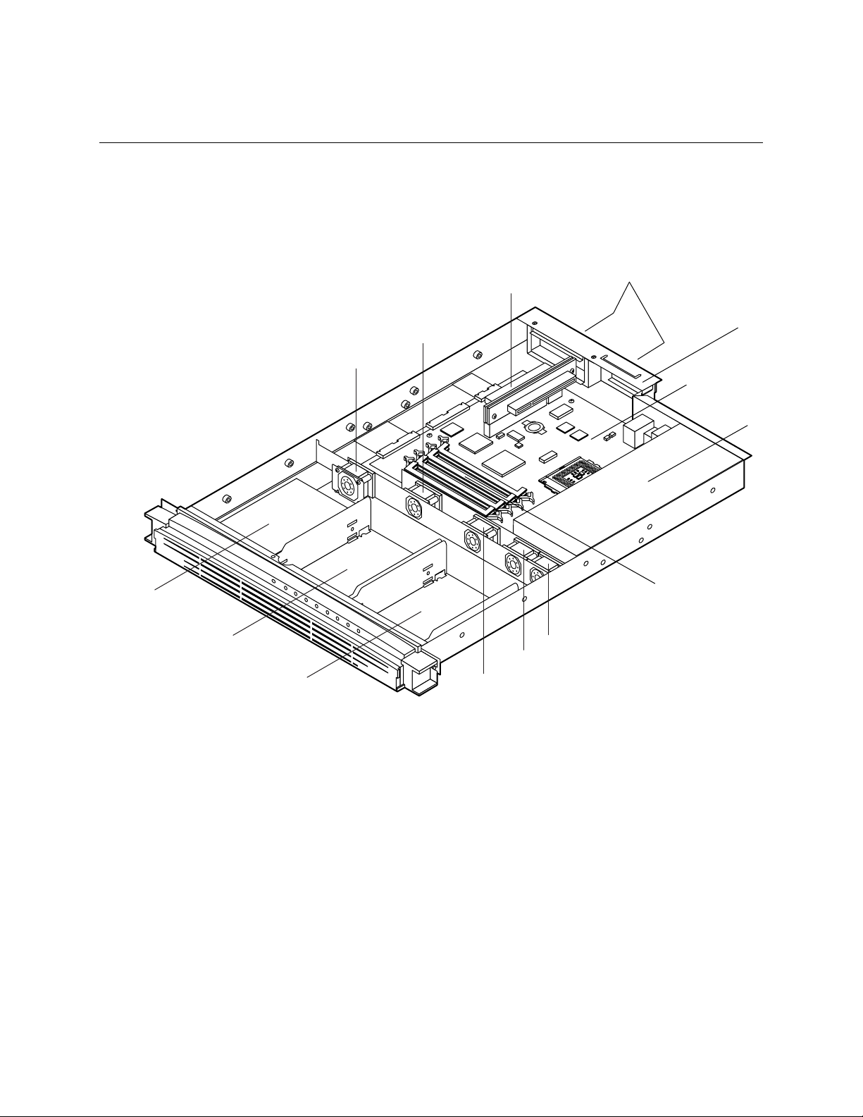
Figure 1 shows the location of the major system components in the Intel® ISP1100 Internet Server.
B
I
J
G
F
E
H
K
L
A
M
C
D
N
OMO9445
A. PCI Add-in Card Slots H. Fan 1
B. PCI Riser Card I. Fan 2
C. Server Board J. Fan 3
D. Power Supply K. Fan 4
E. 1-Inch Hard Drive Bracket L. Fan 5
F. 1-Inch Hard Drive Bracket M. Add-In Card Retention Bracket
G. 3.5-Inch Diskette Drive
N. DIMM Sockets
Figure 1. System Components
7
Page 8

Server Board Features
Table 1 summarizes the TR440BX server board features.
Table 1. Server Board Features
Feature Description
Form Factor MicroATX (9.6 inches by 9.6 inches)
Processor Supports an Intel® Pentium® III processor or Intel Celeron™ processor in a
PGA370 socket.
Memory Four 168-pin dual in-line memory module (DIMM) sockets
Support unbuffered and registered SDRAM DIMMs
Supports up to 1 GB of ECC, SPD SDRAM with registered or unbuffered DIMMs
Chipset Intel® 82440BX AGPset, consists of:
®
Intel
82443BX PCI/AGP controller (PAC)
®
82371EB PCI ISA IDE Xcelerator (PIIX4E)
Intel
I/O Control SMSC FDC37B807 I/O controller
®
Peripheral Interfaces Two integrated Intel
One standard diskette drive interface
One high-density diskette drive interface for slim-line diskette drive
Two IDE interfaces with Ultra DMA/33 support
Two serial ports (1 rear, 1 front)
Two USB ports
†
Two PS/2
LED panel interface
Expansion One PCI bus in combination with a 2x11 riser sideband connector supports a
passive dual-slot PCI riser card (32 bit/33 MHz)
BIOS Intel®/AMI BIOS
Intel® E28F008S585 8-Mbit boot block flash memory
Supports SMBIOS, Advanced Power Management (APM), Advanced
Configuration and Power Interface (ACPI), and Plug and Play
Other Features Speaker
Hardware monitor
Wake on Ring
Wake on LAN
SCSI LED connector
interfaces for keyboard and mouse
Pro/100+ Server (82559) Ethernet controllers
†
8 Intel ISP1100 Internet Server Product Guide
Page 9
Server Board Connectors and Components
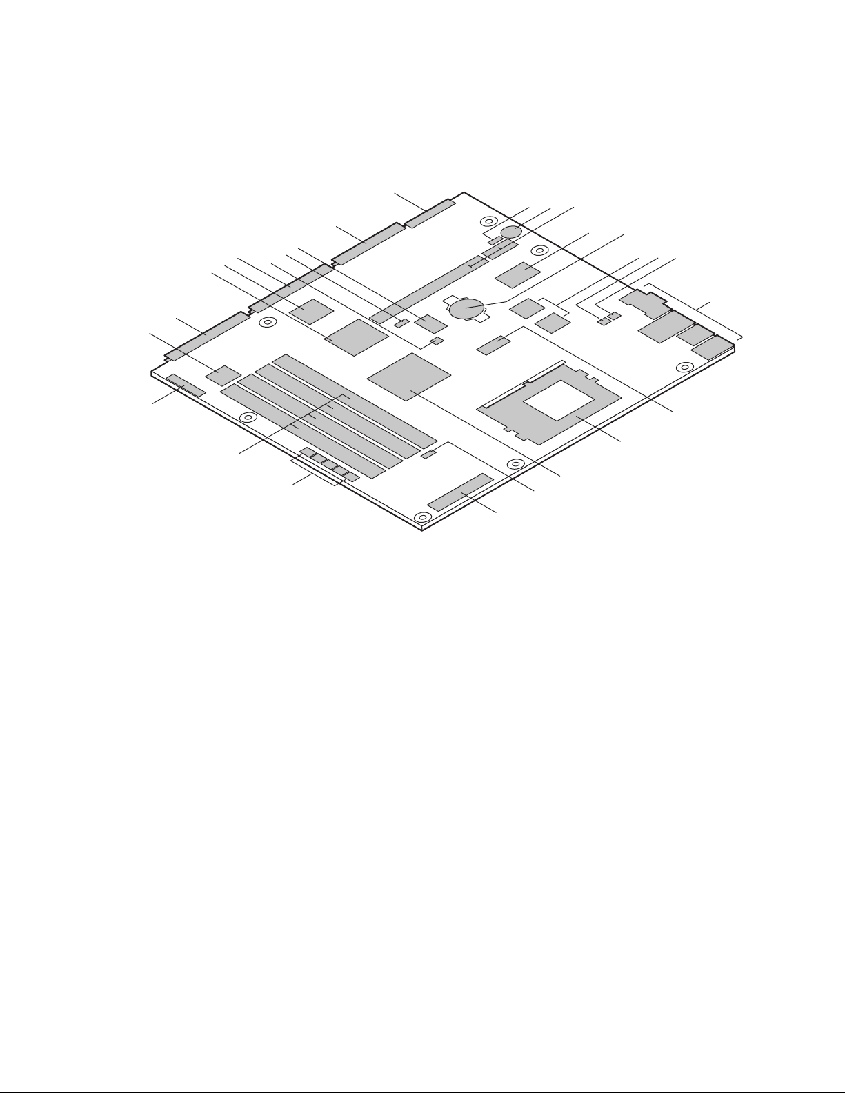
Figure 2 shows the locations of the server board connectors and components.
AA
ABC
Z
Y
V
U
T
S
R
X
W
DE
FGH
I
Q
P
O
N
L
M
K
J
OMO9446
A. Wake on LAN Connector O. System Fans Connectors
B. Speaker P. DIMM Sockets
C. PCI Riser Sideband and PCI Bus Connectors Q. Front Panel Connector
D. SMSC I/O Controller R. Front Panel Controller
E. Battery S. Primary IDE Connector
F. Intel Pro/100+ Server (82559) Ethernet Controllers T. Intel 82371EB PIIX4E
G. SCSI LED Connector U. Gluechip
H. Wake on Ring Connector V. Secondary IDE Connector
I. Back Panel I/O Connectors W. Password Clear Jumper
J. Clock Generator X. BIOS Setup Configuration Jumper
K. PGA370 Processor Socket Y. Flash Memory
L. Intel 82443BX PAC Z. Diskette Drive Connector
M. Heceta 2 Hardware Monitor Controller AA. High-Density Diskette Drive Connector
N. Power Supply Connector
Figure 2. Server Board Connectors and Components
Description 9
Page 10
Controls, Connectors, and Indicators
Front Panel
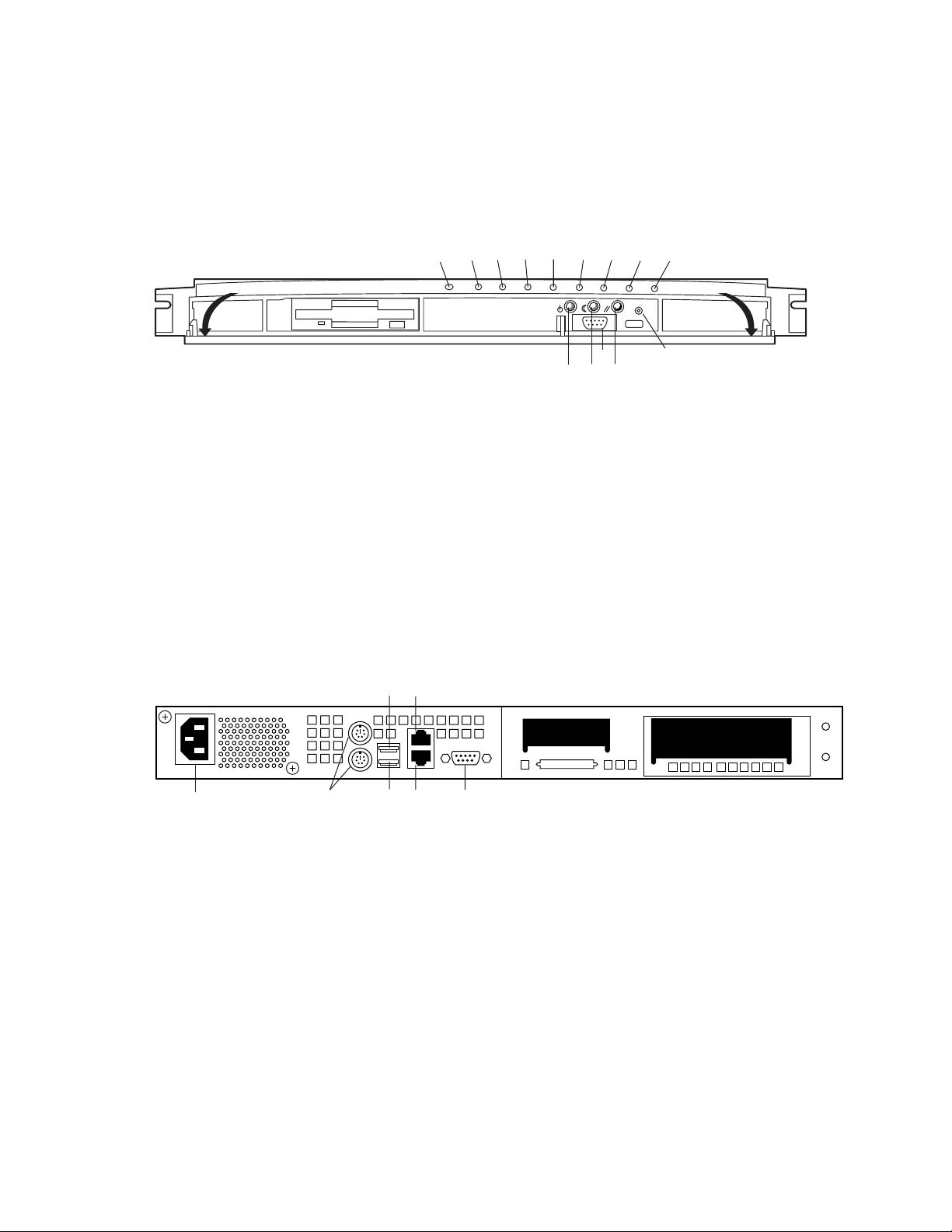
Figure 3 shows the locations of the server front-panel controls, connectors, and indicators.
BEFGHI
A. Power LED Indicator (Green)
B. System Fault LED Indicator (Amber)
C. Hard Drive Activity LED Indicator (Green)
D. LAN 1 Activity LED Indicator (Yellow)
E. LAN 1 100 Mbps LED Indicator (Green)
F. LAN 2 Activity LED Indicator (Yellow)
G. LAN 2 100 Mbps LED Indicator (Green)
H. User-Programmable LED Indicator (Green)
I. User-Programmable LED Indicator (Green)
J. Power Switch
K. Sleep Switch
L. Reset Switch
M. NMI Switch
N. Serial Port B Connector
Figure 3. Front Panel Controls, Connectors, and Indicators
Back Panel
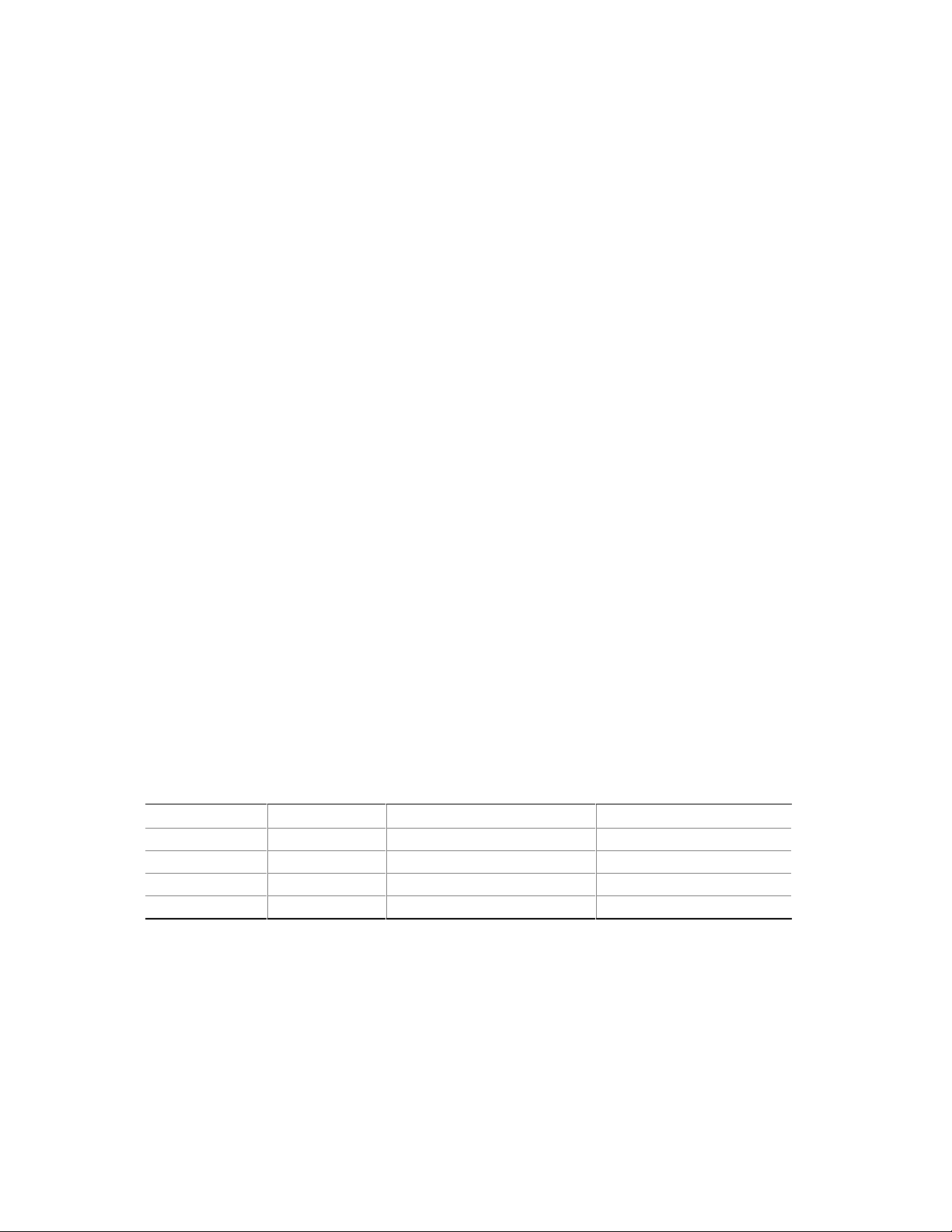
Figure 4 shows the locations of the server back-panel connectors.
CDE
DCA
M
OMO9447
J
N
KL
A
A. AC Power Input Connector E. LAN 2 Connector
B. PS/2 Keyboard/Mouse Connectors F. LAN 1 Connector
C. USB Port 0 Connector G. Serial Port A Connector
D. USB Port 1 Connector
B
FG
OMO9448
Figure 4. Back Panel Connectors
10 Intel ISP1100 Internet Server Product Guide
Page 11

Processors
The server board supports a single Intel Pentium III processor or Celeron processor that plugs into a
PGA370 socket connector that secures the processor chip with a zero-insertion-force (ZIF) arm.
The host bus speed (66 MHz or 100 MHz) is automatically selected. Table 2 lists the processors
supported by the server board.
Table 2. Supported Processors
Processor Type L2 Cache Size FSB Speed Speed
Celeron processor 128 KB 66 MHz
Pentium III processor 256 KB 100 MHz 750 MHz
1
Coppermine 128 KB; other Intel Celeron processors are based on Mendocino core.
566 MHz
533 MHz
500 MHz
466 MHz
433 MHz
400 MHz
366 MHz
700 MHz
650 MHz
600E MHz
550E MHz
500 MHz
1
NOTE
The server board supports Pentium III processors with a 100 MHz host bus
and Celeron processors with a 66 MHz host bus. Processors with a 100 MHz
host bus should be used only with 100 MHz SDRAM. The server board may
not operate reliably if a processor with a 100 MHz host is paired with
66 MHz SDRAM. However, processors with a 66 MHz host can be used
with either 66 MHz or 100 MHz SDRAM.
Memory
The server board has four DIMM sockets. The BIOS determines the SDRAM size and speed using
the serial presence detect (SPD) data structure programmed into an EEPROM on the DIMM.
Memory size is 16 MB to 1 GB. DIMM board memory size can be mixed but must be either all
unbuffered or registered. Slot vacancies are allowed.
The server board supports the following memory features:
• 168-pin SPD DIMMs with gold-plated contacts.
• 66 MHz or 100 MHz unbuffered or registered SDRAM, 72-bit ECC, 3.3 V only memory.
• Single- or double-sided DIMMs in the sizes listed in Table 3.
Description 11
Page 12

• Unbuffered DIMMs of the following sizes: 16 MB, 32 MB, 64 MB, 128 MB and 256 MB for a
total memory size of 1 GB.
• Registered DIMMs of the following sizes: 64MB, 128Mb and 256MB for a maximum memory
size of 1 GB. Only non-stacked DIMMs are supported because of a server board space
constraint.
Table 3. Supported Memory Characteristics
DIMM
Size Configuration
16 MB 2 Mbit x 72 16 Mbit 2 Mbit 8 bit 2 MB x 8 B = 16 MB
32 MB 4 Mbit x 72 16 Mbit 2 Mbit 8 bit 4 MB x 8 B = 32 MB
32 MB 4 Mbit x 72 16 Mbit 4 Mbit 4 bit 4 MB x 8 B = 32 MB
64 MB 8 Mbit x 72 16 Mbit 4 Mbit 4 bit 8 MB x 8 B = 64 MB
32 MB 4 Mbit x 72 64 Mbit 4 Mbit 16 bit 4 MB x 8 B = 32 MB
64 MB 8 Mbit x 72 64 Mbit 4 Mbit 16 bit 8 MB x 8 B = 64 MB
64 MB 8 Mbit x 72 64 Mbit 8 Mbit 8 bit 8 MB x 8 B = 64 MB
128 MB 16 Mbit x 72 64 Mbit 8 Mbit 8 bit 16 MB x 8 B = 128 MB
128 MB 16 Mbit x 72 64 Mbit 16 Mbit 4 bit 16 MB x 8 B = 128 MB
64 MB 8 Mbit x 72 128 Mbit 8 Mbit 16 bit 8 MB x 8 B = 64MB
128 MB 16 Mbit x 72 128 Mbit 8 Mbit 16 bit 16 MB x 8 B = 128 MB
128 MB 16 Mbit x 72 128 Mbit 16 Mbit 8 bit 16 MB x 8 B = 128 MB
256 MB 32 Mbit x 72 128 Mbit 16 Mbit 8 bit 32 MB x 8 B = 256 MB
DRAM
Technology
DRAM
Depth
DRAM
Width
Single-sided DIMM
(Size x 64 Bit)
Double-sided DIMM
(Size x 64 Bit)
When ECC memory is installed, the BIOS supports both ECC and non-ECC mode. ECC mode is
enabled in the BIOS Setup program. The BIOS automatically detects if ECC memory is installed
and provides the Setup option for selecting the ECC mode. If any non-ECC memory is installed,
the Setup option for ECC mode does not appear and ECC operation is not available.
Table 4 describes the effect of using Setup to put each memory type in each supported mode.
Table 4. Memory Error Detection Mode
DIMM Type ECC Disabled ECC Enabled
ECC No error detection S i ngl e-bi t error correction, multiple-bit error detecti on
Non-ECC No error detection N/ A
12 Intel ISP1100 Internet Server Product Guide
Page 13

NOTE
All memory components used with the server board should comply with the
following PC SDRAM specifications (see Chapter 13 in the Intel
Internet Server Technical Product Specification for information about how to
obtain these specifications):
• PC SDRAM Specification (memory component specific)
• PC Unbuffered SDRAM Specifications
• PC Serial Presence Detection Specification
Processors with 100 MHz host bus speed must be paired only with 100 MHz
SDRAM. Processors with 66 MHz host bus speed can be paired with either
66 MHz or 100 MHz SDRAM.
®
ISP1100
Chipset
The Intel 82440BX AGPset consists of the Intel 82443BX PAC and the Intel 82371EB PIIX4E
bridge chip. The PAC provides an optimized DRAM controller. The PAC’s accelerated graphics
port (AGP) interface is not used. The I
which is a highly integrated PCI ISA IDE Xcelerator Bridge.
Universal Serial Bus
The server board has two universal serial bus (USB) ports that accommodate one USB peripheral
connected to each port. For more than two USB devices, an external hub can be connected to either
port. The two USB ports are implemented with stacked back panel I/O connectors. The server
board fully supports UHCI and uses UHCI-compatible software drivers. See Chapter 13 in the Intel
ISP1100 Internet Server Technical Product Specification for information about the USB and UHCI
specifications.
/O subsystem of the 82440BX is based on the PIIX4E,
The USB includes the following capabilities:
• Self-identifying peripherals that can be plugged in while the computer is running.
• Automatic mapping of function to driver and configuration.
• Support for synchronous and asynchronous transfer types over the same set of wires.
• Guaranteed bandwidth and low latencies appropriate for telephony, audio, and other
applications.
• Error-handling and fault-recovery mechanisms built into the protocol.
NOTE
Computer systems that have an unshielded cable attached to a USB port may
not meet FCC Class B requirements; even if no device or a low-speed USB
device is attached to the cable. Use shielded cable that meets the
requirements for full-speed devices.
Description 13
Page 14

IDE Support
The server board has two independent bus-mastering IDE interfaces that support:
1. ATAPI devices (such as CD-ROM drives).
2. ATA devices using the transfer modes listed in the Intel ISP1100 Internet Server Technical
Product Specification.
The BIOS supports logical block addressing (LBA) and extended cylinder head sector (ECHS)
translation modes. The drive reports the transfer rate and translation mode to the BIOS.
The server board supports PCMCIA ATA Type II flash card technology through its IDE interfaces.
No special driver is needed for a PCMCIA ATA Type II flash drive since most operating systems
see it as standard IDE drive.
Real-Time Clock, CMOS SRAM, and Battery
The real-time clock is compatible with DS1287 and MC146818 components. The clock provides a
time-of-day clock and a multi-century calendar with alarm features and century rollover. The realtime clock supports 256 bytes of battery-backed CMOS SRAM in two banks that are reserved for
BIOS use.
A coin-cell Lithium battery powers the real-time clock and CMOS memory. When the computer is
not plugged into an AC power source, the battery has an estimated life of three years. When the
computer is plugged into an AC power source, the 3.3 V standby current from the power supply
extends the life of the battery. The clock is accurate to ±13 minutes/year at 25ºC with 3.3 V
standby applied.
The time, date, and CMOS values can be specified and the CMOS values can be returned to their
defaults in the BIOS Setup program.
NOTE
The recommended method for accessing the date in systems with Intel server
boards is indirectly from the real-time clock (RTC) via the BIOS. The BIOS
on the server board contains a century checking and maintenance feature that
checks the two least significant digits of the year stored in the RTC during
each BIOS request (INT 1Ah) to read the date. If the year is less than 80
(when 1980 is the first year supported by the PC), the BIOS updates the
century byte to 20 which enables operating systems and applications that use
the BIOS date/time services to reliably manipulate the year as a four-digit
value.
For more information on a proper date access in systems with Intel server
boards, please see: h ttp://support.intel.com/support/year2000 /
14 Intel ISP1100 Internet Server Product Guide
Page 15

I/O Controller
The FDC37B807 I/O controller from SMSC is an ISA Plug and Play-compatible, multifunctional
I/O device that provides the following features (see Chapter 13 in the Intel ISP1100 Internet Server
Technical Product Specification for Plug and Play specification information):
• Two serial ports.
• Interface for one 1.2 MB, 1.44 MB, or 2.88 MB diskette drive.
• Three-mode diskette drive support (driver required).
• FIFO support on both serial and diskette drive interfaces.
• One parallel port with extended capabilities port (ECP) and enhanced parallel port (EPP)
support.
• PS/2-style mouse and keyboard interfaces.
• Support for serial IRQ packet protocol.
• Intelligent power management, including:
Shadowed write-only registers for ACPI compliance.
Programmable wake up event interface.
The BIOS Setup program provides configuration options for the I/O controller.
Serial Ports
The server board has two 9-pin D-Sub serial port connectors; one on the back panel and one on the
front panel under the bezel. The front-panel serial port is connected in parallel with the serial port
B D-Sub connector located on the back panel. The serial port NS16C550-compatible UARTs
support data transfers at speeds up to 115.2 Kbits/sec with BIOS support. The serial ports can be
assigned as COM1 (3F8h), COM2 (2F8h), and COM3 (3E8h).
Diskette Drive Controller
The I/O controller supports a single diskette drive that is compatible with the 82077-diskette drive
†
controller and supports both PC-AT
interface can be configured for the following capacities and sizes:
• 360 KB, 5.25-inch
• 1.2 MB, 5.25-inch
• 720 KB, 3.5-inch
• 1.2 MB, 3.5-inch (driver required)
• 1.25/1.44 MB, 3.5-inch
• 2.88 MB, 3.5-inch
and PS/2 modes. In the Setup program, the diskette driver
NOTE
The I/O controller supports 1.2 MB, 3.5-inch diskette drives, but a special
driver is required (three-mode).
Description 15
Page 16
Keyboard and Mouse Interface
The PS/2 keyboard and mouse connectors are located on the server back panel. The +5 V lines to
†
these connectors are protected with a PolySwitch
the connection after an overcurrent condition is removed.
The keyboard controller contains the AMI keyboard and mouse controller code, provides the
keyboard and mouse control functions, and supports password protection for power on/reset. A
power on/reset password can be specified in the BIOS Setup.
The keyboard controller also supports the hot-key sequence <Ctrl><Alt><Del> for a software
reset. This key sequence resets the computer software by jumping to the beginning of the BIOS
code and running the Power-On Self-Test (POST).
circuit that, like a self-healing fuse, reestablishes
NOTE
The mouse and keyboard can be plugged into either of the PS/2 connectors.
Turn off AC power to the computer before a keyboard or mouse is connected
or disconnected.
Hardware Monitor
A Heceta 2 system monitor controller is provided on the server board to monitor temperature,
voltage, fan speed and a temperature sensor located on the front panel. Temperature is monitored
through a sensor internal to the Heceta 2 that indicates the ambient temperature of the area of the
board in which the Heceta 2 IC is located. The Heceta 2 monitors +5V, +3.3V, +12V, –12V,
+1.5V, and the processor core voltage. The Heceta 2 may be used to monitor the speed of a fan that
has a tachometer output connected to any of the five auxiliary fan connectors. The five system fan
tachometer outputs are multiplexed to the Heceta 2 device to allow individual monitoring. The
software through the PIIX4 chip controls the multiplexing of the fan tachometer outputs to the
Heceta 2 chip. The multiplexer control bits (FAN_MUXCTL0 and FAN_MUXCTL1) are
connected to the PIIX4 are connected to the outputs GPO0 and GPO13, respectively. Table 5
shows the fan tachometer mapping.
Table 5. Fan Tachometer MUX Control Mapping
Fan_MUXCTL0 Fan_MUXCTL1 Heceta FAN1_TACH Input Heceta FAN2_TACH Input
0 0 Fan 1 (J35) Fan 4 (J38)
0 1 Fan 2 (J34) Fan 5 (J37)
1 0 Fan 3 (J33) NONE
1 1 NONE NONE
The Heceta 2 is set up and interfaced through the PIIX4 SMBUS interface. Out of band or absolute
thresholds may be set for many of the monitored functions using the SMBUS interface. Threshold
faults are available by polling the Heceta 2 via the SMBUS interface. The Heceta 2 updates its
information approximately every 1 second.
16 Intel ISP1100 Internet Server Product Guide
Page 17

For more details on programming and reading the Heceta 2 chip please refer to the Heceta 2 Device
Specification version 1.2 or later (see Chapter 13 in the Intel ISP1100 Internet Server Technical
Product Specification for how to obtain this specification).
SCSI Hard Drive LED Connector
The optional SCSI hard drive LED connector is a 1 x 2-pin connecto r that allows add-in SCSI
controller applications to use the same LED as the IDE controller. This connector can be connected
to the LED output of the add-in controller card (see Chapter 13 in the Intel ISP1100 Internet Server
Technical Product Specification for the location and pinouts of the SCSI hard drive LED
connector).
Intel® Pro/100+ Server (82559) Ethernet Controllers
Two Intel Pro/100+ Server (82559) Ethernet controllers provide two 10/100 Base-T interfaces
accessible from the back panel (see Chapter 13 in the Intel ISP1100 Internet Server Technical
Product Specification for the location and pinouts of the LAN connectors).
The LAN connectors on the back panel do not provide LEDs to indicate transmit/receive activity
and speed. Instead, these indicators are routed to four LEDs on the front panel. See “Controls,
Connectors, and Indicators” for LED locations and definitions.
Alert on LAN and Wake on LAN features are supported by the TR440BX server board software
and the SMBUS interface of the Intel 82559s. See the BIOS specification for information
regarding Alert on LAN and Wake on LAN. Also see “Wake on LAN” for more information.
CAUTION
For Wake on LAN, the 5V standby line for the power supply must be capable
of delivering +5V ±5% at 720 mA. Failure to provide adequate standby
current, when implementing Wake on LAN can damage the power supply.
Wake on LAN
Wake on LAN enables remote wakeup of the computer through a network. If a PCI add-in network
interface card (NIC) with remote wakeup capabilities is desired, the remote wakeup connector on
the NIC must be connected to the onboard Wake on LAN connector.
The integrated LAN controllers or the add-in NIC monitors network traffic at the MII interface.
Upon detecting a Magic Packet, the LAN controllers or NIC assert a wakeup signal that powers up
the computer.
To access this feature, use the optional Wake on LAN connector on the server board. See “Server
Board Connectors and Components” for the location and definition of the Wake on LAN connector.
Description 17
Page 18

Wake on Ring/Resume on Ring
Wake on Ring enables the computer to wake from sleep or soft-off mode when a call is received on
a telephony device, such as a faxmodem. The server board provides three methods for
implementing Wake on Ring:
1. An external modem connected to Serial Port A (rear) can toggle the super I/O controller’s Ring
Indicator pin which should be enabled to cause a wakeup event.
2. The 2-pin Wake on Ring header may be shorted to cause a wakeup event.
3. A PCI modem may implement a Wake on Ring circuit that uses PCI PME# to cause a wakeup
event.
This section describes two technologies that enable telephony devices to access the computer when
it is in a power-managed state. The method used depends on the type of telephony device (external
or internal) and the power management mode used (APM or ACPI).
NOTE
Wake on Ring and Resume on Ring technologies require the support of an
operating system that provides full ACPI functionality.
Wake on Ring
The operation of Wake on Ring can be summarized as follows:
1. Powers up the computer from either the APM soft-off mode or the ACPI S5 state.
2. Requires two calls to access the computer:
• First call powers up the computer.
• Second call enables access (when the appropriate software is loaded).
3. Detects incoming call differently for external as opposed to internal modems:
• For external modems, server-board hardware monitors the ring indicate (RI) input of serial
port A and B.
• For internal modems, a cable must be routed from the modem to the Wake on Ring
connector.
See “Server Board Connectors and Components” for the location and definition of the Wake on
Ring connector.
Resume on Ring
The operation of Resume on Ring can be summarized as follows:
1. Resumes operation from either the APM sleep mode or the ACPI S1 state.
2. Requires only one call to access the computer.
3. Detects incoming calls similarly for external and internal modems. Does not use the Wake on
Ring connector.
4. Requires modem interrupt be unmasked for correct operation.
18 Intel ISP1100 Internet Server Product Guide
Page 19

SMI and NMI Routing
There are numerous SMI sources and all are routed to the PIIX4. Software must configure the
PIIX4 SMI source pins to control whether SMI is propagated through to the processor via its
H_SMI input or not. For details on the fault conditions that cause SMI to occur, consult the data
sheets of the SMI source ICs. The SMI routing on the server board is described in Table 6. Note
that some PIIX4 inputs have several sources. Schematic signal names are in parenthesis.
Table 6. SMI and NMI Routing
SMI Source PIIX4 Input Pin
BX Chipset PCI SERR# - used for ECC Errors (P_SERR#) EXT_SMI#
LAN PCI SERR# (P_SERR#) EXT_SMI#
All three PCI Slot’s SERR# (P_SERR#) EXT_SMI#
Gluechips EXTSMI# output – used for +5 VSB errors GPI13
Gluechips EXTSMI# output – Through buffer to (P_SERR#) EXT_SMI#
LAN1 PCI PME# (P_PME#) GPI1
LAN2 PCI PME# (P_PME#) GPI1
All three PCI slot’s PME# (P_PME#) GPI1
Super I/O Serial Interrupt SMI – used for watchdog timer
(SER_IRQ)
Super I/O PME# (SIO_RIA#) – originally from WOR header or
ext. modem
Wake on LAN header – used for Wake on LAN (WOL#) LID
SER_IRQ
RIAB
The Gluechips EXT_SMI# output is also connected to the PIIX4 GPI13 pin to provide a status of
the Gluechips EXT_SMI# signal.
All NMI generation on the server board is under software control. Writes to PIIX4 GPO17 are
routed to the PIIX4 IOCHK# input which may be configured to cause a NMI to occur. Thus,
software may cause a NMI to occur by pulsing GPO17 active.
The TR440BX server board BIOS SMI handler detects SMI events, logs the events, and elevates
selected events to NMI level.
Power Connector
When used with an ATX-compliant power supply that supports remote power on/off, the server
board can turn off the system power through software control.
Speaker
A 47-ohm inductive speaker is mounted on the server board. The speaker provides audible error
code (beep code) information during the Power-On Self-Test (POST).
Description 19
Page 20

Fan Support
The server board has five fan connectors. The functions of the fan connectors are described in
Table 7.
Table 7. Fan Connector Descriptions
Connector Function
Fan 1 (J35) Supports fan speed sensing for fans with tachometer outputs. Connector supports
variable fan speed.
Fan 2 (J34) Supports fan speed sensing for fans with tachometer outputs. Connector supports
variable fan speed.
Fan 3 (J33) Supports fan speed sensing for fans with tachometer outputs. Connector supports
variable fan speed.
Fan 4 (J38) Supports fan speed sensing for fans with tachometer outputs. Connector supports
on/off fan control or variable fan speed via a fuse-stuffing option.
Fan 5 (J37) Supports fan speed sensing for fans with tachometer outputs. Connector supports
on/off fan control or variable fan speed via a fuse-stuffing option.
20 Intel ISP1100 Internet Server Product Guide
Page 21

2 Removing/Installing Server Components
This chapter provides procedures for removing and installing replaceable and/or upgradable
components in the Intel ISP1100 Internet Server. Before performing the procedures, be sure to
familiarize yourself with the following “Before You Begin” information.
Before You Begin
FCC/Emissions Disclaimer
This equipment has been tested and verified to comply with Class B limits when configured into a
compatible host computer, pursuant to Part 15 of the FCC Rules, CISPR 22, and EN55022. These
limits are designed to provide reasonable protection against harmful interference in a residential
installation. This equipment generates, uses, and can radiate radio frequency energy and, if not
installed and used in accordance with the instructions, may cause harmful interference to radio
communications. However, there is no guarantee that interference will not occur in a particular
installation. If this equipment does cause harmful interference to radio or television reception,
which can be determined by turning the equipment off and on, the user is encouraged to try to
correct the interference by one or more of the following measures:
• Reorient or relocate the receiving antenna.
• Increase the separation between the equipment and receiver.
• Connect the equipment into an outlet on a circuit different from that to which the receiver is
connected.
• Consult the dealer or an experienced radio/TV technician for help.
To ensure EMC compliance with your local regional rules and regulations, the final configuration
of your end system product may require additional EMC compliance testing. For more information
please contact your supplier
.
Warnings and Cautions
Read and adhere to all warnings, cautions, and notes in this guide and the documentation referenced
and supplied with the server. If the additional instructions supplied with the server are inconsistent
with these instructions, contact the supplier to find out how you can ensure that your server meets
safety and regulatory requirements.
21
Page 22

WARNINGS
This chapter is intended for qualified technical personnel with
experience installing and configuring servers.
SYSTEM POWER ON/OFF: The Power button on the server front
panel DOES NOT remove AC power to the server system. Some
circuitry in the server may continue to operate even though the front
panel Power button is off. Always disconnect the power cord from the
AC power source or wall outlet before performing any of the procedures
in this guide. Failure to do so can result in personal injury or equipment
damage.
HAZARDOUS CONDITIONS, POWER SUPPLY: Hazardous voltage,
current, and energy levels are present inside the power supply. There
are no user-serviceable parts inside the power supply; servicing should
be done by technically qualified personnel.
HAZARDOUS CONDITIONS, DEVICES, AND CABLES: Hazardous
electrical conditions may be present on power, telephone, and
communication cables. Press the Power button to turn off the server
and disconnect the power cord from the AC power source,
telecommunications systems, networks, and modems attached to the
server before removing the cover. Otherwise, personal injury or
equipment damage can result.
CAUTIONS
ELECTROSTATIC DISCHARGE (ESD) AND ESD PROTECTION:
Perform the procedures in this chapter only at an elec tro st at ic discharge
(ESD) workstation since the server components can be extremely sensitive to
ESD. If no such station is available, you can reduce the risk of electrostatic
discharge ESD damage by doing the following:
• Wear an antistatic wrist strap and attach it to a metal part of the server.
• Touch the metal on the server chassis before touching the server components.
• Keep part of your body in contact with the metal server chassis to dissipate the static
charge while handling the components.
• Avoid moving around unnecessarily.
• Hold the server components (especially boards) only by the edges.
• Place the server components on a grounded, static-free surface. Use a conductive foam
pad if available but no t the component wrapper.
• Do not slide the components over any surface.
COOLING AND AIRFLOW: For proper cooling and airflow, always
install the chassis access cover before turning on the system. Operating the
system without the cover in place can cause overheating and damage to
system parts.
22 Intel ISP1100 Internet Server Product Guide
Page 23

Rackmount Precautions
Familiarize yourself with the follow ing preca ut ions befo re rac kmo unt ing the ser ver.
WARNINGS
ANCHOR THE EQUIPMENT RACK: The equipment rack must be anchored
to an unmovable support to prevent it from falling over when one or
more devices are extended in front of it on slide assemblies. The anchors
must be able to withstand a force of up to 113 kg (250 lbs.). You must
also consider the weight of any other device installed in the rack.
M
AIN AC POWER DISCONNECT: You are responsible for installing an
AC power disconnect for the entire rack unit. This main disconnect
must be readily accessible, and it must be labeled as controlling power to
the entire unit, not just to the server(s).
ROUNDING THE RACK INSTALLATION: To avoid the potential for
G
electrical shock, you must include a third wire safety grounding
conductor with the rack installation. If server power cords are plugged
into AC outlets that are part of the rack, then you must provide proper
grounding for the rack itself. If server power cords are plugged into
wall AC outlets, the safety grounding conductor in each power cord
provides proper grounding only for the server. You must provide
additional, grounding for the rack and other devices installed in it.
OVERCURRENT PROTECTION: The server is designed for an AC
line voltage source with up to 20 amperes of overcurrent protection. If
the power system for the equipment rack is installed on a branch circuit
with more than 20 amperes of protection, you must provide
supplemental protection for the server. If more than one server is
installed in the rack, the power source for each server must be from a
separate branch circuit.
CAUTIONS
TEMPERATURE: The operating temperature of the server, when installed
in an equipment rack, must not go below 5 °C (41°F) or rise above 35 °C
(95 °F). Extreme fluctuations in temperature can cause a variety of server
problems.
VENTILATION: The equipment rack must provide sufficient airflow to the
front of the server to maintain proper cooling. There must be sufficient
ventilation to exhaust at least 1,500 BTU per hour for each server. The rack
selected and the ventilation provided must be suitable to the environment in
which the server will be used.
Removing/Installing Server Components 23
Page 24

Safety and Regulatory Requirements
This product was evaluated for use in computer racks within computer rooms and similar locations.
Other uses require further evaluation.
Safety Compliance
USA/Canada
Europe
International
UL 1950, 3rd Edition/CSA 22.2, No. 950M93, 3rd Edition
Low Voltage Directive, 73/23/EEC
TUV/GS to EN60950 2nd Edition with Amendments, A1 = A2 + A3 + A4
CB Certificate and Report to IEC 60950, 3rd Edition including EMKO-TSE (74-
SEC) 207/94 and other national deviations
Electromagnetic Compatibility (EMC)
USA
Canada
Europe
Australia/New Zealand
Japan
Taiwan
Russia
International
FCC 47 CFR Parts 2 and 15, Verified Class A Limit
IC ICES-003 Class A Limit
EMC Directive, 89/336/EEC
EN55022, Class A Limit, Radiated & Conducted Emissions
EN55024, Immunity Standard for Information Technology Equipment
EN61000-3-2 Harmonic Currents
EN61000-3-3 Voltage Flicker
AS/NZS 3548, Class A Limit
VCCI Class A ITE (CISPR 22, Class A Limit).
IEC 1000-3-2; Harmonic Currents
BSMI, Class A (CISPR 22)
Gost Approval
CISPR 22, Class A Limit
Tools and Supplies Needed
1. Phillips (cross-head) screwdriver (number 1 and 2 bit)
2. Flat-head screwdriver (3/16-inch)
3. Jumper removal tool or needle nosed pliers
4. Pen or pencil
5. Antistatic wrist strap and conductive foam pad (recommended)
Removing the Server From the Rack
This procedure describes how to remove the server from the rack. Before proceeding, be sure you
are thoroughly familiar with the information in “Before You Begin” at the front of this chapter.
Refer to Figure 5 while performing this procedure.
1. Use a Phillips screwdriver to remove the two screws (C) that secure the server mounting
brackets to the rack posts (B).
2. Carefully remove the server from the front of the rack.
24 Intel ISP1100 Internet Server Product Guide
Page 25
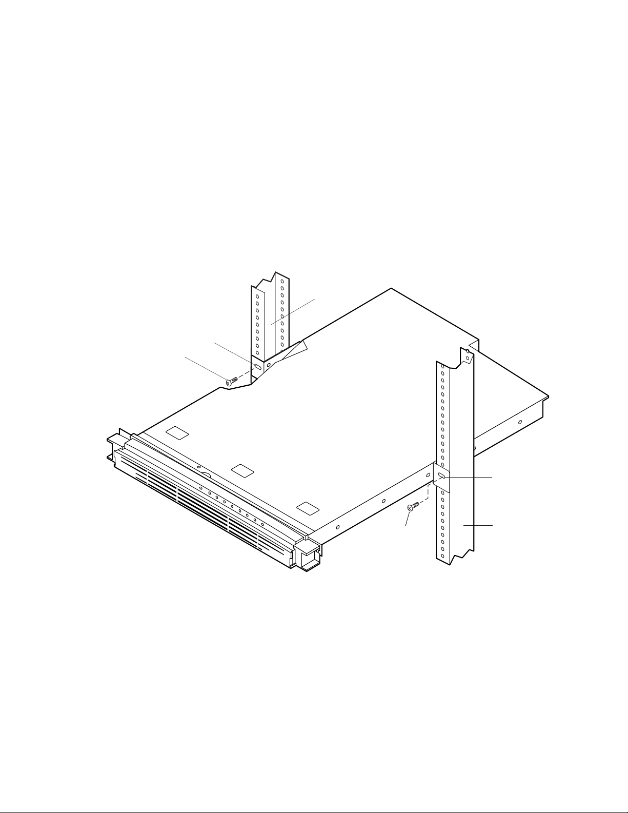
Installing the Server in the Rack
This procedure describes how to install the server in the rack. Before proceeding, be sure and
familiarize yourself with the “Rackmount Precautions” information in the “Before You Begin”
section at the front of this chapter. Refer to Figure 5 while performing this procedure.
1. Orient the server with the rackmount brackets aligned with the desired mounting holes (A) in
the rack posts (B).
2. Use a Phillips screwdriver and start the two screws removed in the previous “Removing the
Server From the Rack” procedure and loosely attach the mounting brackets (one on each side of
the server) to the rack posts. Do not tighten.
3. Properly align the server in the rack.
4. Use a Phillips screwdriver and tighten the two screws (C) to securely attach the mounting
brackets to the rack posts.
B
A
C
C
Figure 5. Removing/Installing the Server in the Rack
A
B
OMO9442
Removing/Installing Server Components 25
Page 26

Removing the Cover
This procedure describes how to remove the cover from the server. Before proceeding, be sure you
are thoroughly familiar with the information in “Before You Begin” at the front of this chapter.
Refer to Figure 6 while performing this procedure.
1. Use a Phillips screwdriver and remove the screw (A) from the front edge of the cover.
2. Grasp the back edge of the cover and simultaneously pull from the back edge and push near the
front until the cover slides out from under the edge of the server front panel.
3. Grasp the notch (B) in the front center of the cover and lift to remove the cover.
Replacing the Cover
This procedure describes how to replace the cover on the server. Before proceeding, be sure you
are thoroughly familiar with the information in “Before You Begin” at the front of this chapter.
Refer to Figure 6 while performing this procedure.
1. Position the cover on the chassis with the notched edge (B) facing the front and the slotted sides
of the cover inside the chassis frame.
2. Grasp the back edge of the cover and simultaneously push from the back and top until the front
edge of the cover slides all the way under the edge of the server front panel.
3. Use a Phillips screwdriver and the screw (A) removed in the previous “Removing the Cover”
procedure to securely attach the cover to the chassis.
A
B
OMO9449
Figure 6. Removing/Replacing the Cover
26 Intel ISP1100 Internet Server Product Guide
Page 27

Removing the Processor
This procedure describes how to remove the processor on the server board. Before proceeding, be
sure you are thoroughly familiar with the information in “Before You Begin” at the front of this
chapter.
WARNING
If the server has been running recently, the processor chip, heat sink,
and adjacent components will be hot. To avoid burns, allow time for the
processor chip, heat sink, and adjacent components to cool before you
proceed with these procedures.
Removing the Proc essor Heat Sink
Perform this procedure to remove the heat sink from the processor. Refer to Figure 7 while
performing this procedure.
1. Use a slotted screwdriver and insert the tip into the top slot in the end of the heat sink clamp
(A) that has two slots.
2. Press down on the top of the clamp (B) while gently prying back on the screwdriver until the
front of the clamp is loose from the tab (C) on the processor socket.
3. Grasp the front and back of the clamp and gently lift the front of the heat sink until the rear of
the clamp releases from the tab on the processor socket.
4. Remove the clamp.
5. Lift the heat sink from the processor chip.
A
OMO9450
C
Figure 7. Removing the Processor Heat Sink
Removing/Installing Server Components 27
B
Page 28

Removing the Processor Chip
Perform this procedure to remove the processor chip from the socket. Refer to Figure 8 while
performing this procedure.
1. Face the front of the server and grasp the end of the zero-insertion-force (ZIF) arm (A) on the
left side of the processor socket.
2. Bend the ZIF arm slightly to the left until it disengages from the socket tab (B).
3. Swing the arm up until it stops in the straight up position. The processor chip is now loose in
the socket.
4. Grasp the processor chip on the outside edges and lift it from the socket.
A
B
OMO9451
Figure 8. Removing the Processor Chip
Installing the Processor
This procedure describes how to install the processor on the server board. Before proceeding, be
sure you are thoroughly familiar with the information in “Before You Begin” at the front of this
chapter.
CAUTION
Processor must be appropriate: You can cause damage to the server if
you install an incompatible processor. See Chapter 1 for the supported
processor characteristics (note the thermal and power considerations).
For exact information about processor interchangeability, contact the
supplier.
28 Intel ISP1100 Internet Server Product Guide
Page 29

Removing the Proc essor Fan (If Applicable )
This procedure describes how to remove the processor fan from a replacement processor. Due to
space constraints, the server will not accommodate a processor with a fan mounted on the heat sink.
Sufficient cooling is provided in the server without the processor fan.
If the processor you wish to install has a fan mounted on top of the heat sink, remove the fan as
described in the following procedure. Otherwise, proceed to “Installing the Processor Chip.” Refer
to Figure 9 while performing this procedure.
1. Grasp the fan housing at each corner.
2. Gently press and lift on the corners until the fan releases from the heat sink.
OMO9430
Figure 9. Removing the Processor Fan
Removing/Installing Server Components 29
Page 30

Installing the Processor Chip
Perform this procedure to install the processor chip in the socket. Refer to Figure 10 while
performing this procedure.
1. Grasp the end of the zero-insertion-force (ZIF) arm (A) and bend it out slightly until it
disengages from the socket tab (B).
2. Swing the ZIF arm up until it stops in the straight up position. The processor socket is now
unlocked.
3. Face the front of the server and orient the processor chip (C) with the notch (D) in the upper left
corner of the processor socket (E).
4. Gently place the processor chip on the socket so that the processor pins (F) mate exactly with
the corresponding socket pins (G). Do not force the processor into the socket since it takes
only a slight pressure to bend the pins.
5. With the processor in place, swing the arm (A) down until it snaps into the socket tab (B). The
processor is now properly socketed.
D
C
A
B
Figure 10. Installing the Processor Chip
F
E
G
OMO9431
30 Intel ISP1100 Internet Server Product Guide
Page 31

Installing the Processor Heat Sink
Perform this procedure to install the heat sink on the processor chip. Refer to Figure 11 while
performing this procedure.
1. Orient the heat sink so the thermal grease pad (A) on the heat sink is exactly aligned with the
corresponding thermal grease pad (B) on top of the processor chip.
2. With the end of the clamp that has the two slots (C) facing the front of the socket, drop the
clamp in the bottom of the heat sink center groove (D).
3. Make sure the end of the clamp with the two slots (C) is positioned just below the top edge of
the heat sink and press down on the back of the clamp (E) until it snaps onto the socket tab (F).
4. With the front of the clamp below the top edge of the heat sink, press down on the front of the
clamp (G) until it snaps onto the socket tab (H).
A
D
G
B
C
H
Figure 11. Installing the Processor Heat Sink
E
F
OMO9432
Removing/Installing Server Components 31
Page 32

Removing the DIMM Boards
This procedure describes how to remove DIMM boards from the server board sockets. Before
proceeding, be sure you are thoroughly familiar with the information in “Before You Begin” at the
front of this chapter. Refer to Figure 12 while performing this procedure.
1. Grasp the ejector lever (A) on one end of the DIMM board and push down on the lever until the
end of the board edge connector (B) just lifts out of the server board socket (C).
CAUTION
Hold the tips of your fingers lightly on the back edge (D) of the DIMM board
to prevent the board from suddenly ejecting from the socket (C) when you
perform step 2 of this procedure. The DIMM board or other components on
the server board could be damaged if the DIMM board is allowed to
suddenly eject from the socket.
2. Grasp the ejector lever (E) on the other end of the DIMM board and carefully push down on the
lever until the DIMM board is loose from the socket.
E
C
B
Figure 12. Removing the DIMM Boards
D
A
OMO9452
32 Intel ISP1100 Internet Server Product Guide
Page 33

Installing the DIMM Boards
This procedure describes how to install DIMM boards on the server board. Before proceeding, be
sure you are thoroughly familiar with the information in “Before You Begin” at the front of this
chapter. Refer to Figure 13 while performing this procedure.
CAUTIONS
Make sure that the DIMM board(s) you wish to install has the appropriate
characteristics. See Chapter 1 for the required characteristics of the
supported memory.
Use extreme care when installing a DIMM board. Applying too much
pressure or misaligning the board in the socket can damage the sockets or
DIMM board edge connectors. DIMM board edge connectors are keyed and
can be inserted only one way.
You can reduce the risk of damaging a connector by installing the DIMM
boards starting with the back socket on the server board and move toward the
front of the server.
Mixing dissimilar metals can cause memory failures that result in data
corruption. The DIMM board sockets on the server board are gold plated.
Thus, only install DIMM boards with gold-plated edge connectors.
1. Orient the DIMM board so the key slots (A) in the DIMM board edge connector are properly
aligned with the corresponding slots in the mating server board socket (B). (The connectors are
keyed to mate in only one direction.)
2. Firmly press the DIMM board straight down and all the way into the server board socket.
3. Make sure the DIMM board is locked in by pressing the levers (C) on each end of the server
board socket into the mating notches (D) on each edge of the DIMM board.
C
B
A
D
OMO9433
Figure 13. Installing the DIMM Boards
Removing/Installing Server Components 33
Page 34

Removing the Hard Drive(s)
This procedure describes how to remove the hard drives from the server drive bays. Before
proceeding, be sure you are thoroughly familiar with the information in “Before You Begin” at the
front of this chapter. Refer to Figure 14 while performing this procedure.
1. Disconnect the power and data cables (A) from the back of the drive.
2. Grasp the back of the drive and lift until the drive mounting bracket (B) releases from the two
snaptop standoffs (C).
3. Slide the mounting bracket back to release the tabs from the slots (D) in the server front panel.
4. Remove the mounting bracket and drive from the drive bay.
5. Use a Phillips screwdriver and remove the four screws (E) that attach the mounting bracket to
the drive (two on each side).
6. Lift the drive from the mounting bracket.
B
A
D
E
Figure 14. Removing the Hard Drive(s)
C
OMO9453
34 Intel ISP1100 Internet Server Product Guide
Page 35

Installing the Hard Drive(s)
This procedure describes how to install hard drives in the server drive bays. Before proceeding, be
sure you are thoroughly familiar with the information in “Before You Begin” at the front of this
chapter.
Installing the Hard Drive in the Mounting Bracket
Perform this procedure to install the hard drive in the mounting bracket. Refer to Figure 15 while
performing this procedure.
NOTE
This procedure assumes that the mounting bracket has been removed from
the drives as described in the previous “Removing the Hard Drives”
procedure.
1. Place the drive in the mounting bracket with the component side down and the front of the
drive facing the front (tabbed) end (A) of the mounting bracket.
2. Align the four mounting bracket screw holes (B) with the mating holes (two on each side) in
the drive housing.
3. Use a Phillips screwdriver and four screws (C) to securely attach the mounting bracket to the
drive. Do not overtighten the screws because the bracket sides can bend inward which affects
the alignment of the tabs with the slots in the front panel.
C
A
B
C
OMO9454
Figure 15. Installing the Hard Drive in the Mounting Bracket
Removing/Installing Server Components 35
Page 36

Installing the Hard Drive in the Drive Bay
Perform this procedure to install the mounting bracket with the hard drive in the drive bay. Refer to
Figure 16 while performing this procedure.
1. Connect the power and data cables to the back of the drive (D).
2. Position the drive in the server drive bay so that the end of the bracket with the tabs (A) is
facing the server front panel.
3. Gently guide the bracket tabs into the mating slots (B) in the server front panel.
4. Align the two holes in the back of the bracket with the two chas sis snap top sta ndof fs (C).
5. Press down on the back of the mounting bracket until the two snaptop standoffs snap into the
mating holes in the bracket.
B
D
A
C
OMO9436
Figure 16. Installing the Hard Drive in the Drive Bay
36 Intel ISP1100 Internet Server Product Guide
Page 37

Removing the 3.5-inch Diskette Drive
This procedure describes how to remove the 3.5-inch diskette drive from the server drive bay.
Before proceeding, be sure you are thoroughly familiar with the information in “Before You Begin”
at the front of this chapter. Refer to Figure 17 while performing this procedure.
1. Disconnect the power and data cables (A) from the back of the drive.
2. Use a Phillips screwdriver and remove the three screws (B) that secure the mounting bracket
(C) and drive to the server chassis (two on one side and one on the other).
3. Remove the drive mounting bracket and drive.
4. Use a Phillips screwdriver and remove the four screws (D) that secure the mounting bracket to
the drive (two on each side).
5. Lift the drive from the mounting bracket.
B
D
C
D
Figure 17. Removing the 3.5-inch Diskette Drive
A
OMO9455
Removing/Installing Server Components 37
Page 38

Installing the 3.5-inch Diskette Drive
This procedure describes how to install the 3.5-inch diskette drive in the server drive bay. Before
proceeding, be sure you are thoroughly familiar with the information in “Before You Begin” at the
front of this chapter.
Installing the Drive in the Mounting Bracket
Perform this procedure to install the 3.5-inch diskette drive in the mounting bracket. Refer to
Figure 18 while performing this procedure.
NOTE
This procedure assumes that the mounting bracket has been removed from
the server chassis and the drive removed from the bracket as described in the
previous “Removing the 3.5-inch Diskette Drive” procedure.
1. Place the diskette drive in the mounting bracket with the component side down and the front
panel facing the front of the mounting bracket.
2. Use a Phillips screwdriver and the four screws (A) removed in the preceding “Removing the
3.5-inch Diskette Drive” procedure (two on each side) to securely attach the mounting
bracket to the drive.
A
OMO9456
A
Figure 18. Installing the 3.5-inch Diskette Drive in the Mounting Bracket
38 Intel ISP1100 Internet Server Product Guide
Page 39

Installing the 3.5-inch Diskette Drive in the Drive Bay
Perform this procedure to install the mounting bracket and drive in the server drive bay. Refer to
Figure 19 while performing this procedure.
1. Connect the power and data cables (C) to the drive. The red stripe (D) on the data cable
faces toward the center of the drive.
2. Place the mounting bracket and drive in the server chassis and align the three screw holes (A)
in the mounting bracket (two on one side and one on the other) with the mating holes in the
server chassis.
3. Use a Phillips screwdriver and the three screws (B) removed from the mounting bracket in the
preceding “Removing the 3.5-inch Diskette Drive” procedure to securely attach the mounting
bracket and drive to the server chassis.
B
C
A
Figure 19. Installing the 3.5-inch Diskette Drive in the Drive Bay
OMO9457
D
Removing/Installing Server Components 39
Page 40

Removing the PCI Add-in Card(s)
This procedure describes how to remove the PCI add-in card(s) from the server board. Before
proceeding, be sure you are thoroughly familiar with the information in “Before You Begin” at the
front of this chapter.
Removing the Filler Panel Retention Bracket
Perform this procedure to remove the filler panel retention bracket from the server back panel.
Refer to Figure 20 while performing this procedure.
1. Use a Phillips screwdriver and remove the two screws (A) securing the filler panel retention
bracket (B) to the top edge of the server back panel.
2. Remove the retention bracket.
A
B
OMO9458
Figure 20. Removing the Filler Panel Retention Bracket
40 Intel ISP1100 Internet Server Product Guide
Page 41

Removing the Riser and Add-in Ca rd(s)
Perform this procedure to remove the riser and add-in card(s) from the server board. Refer to
Figure 21 while performing this procedure.
CAUTION
Do not attempt to remove an add-in card without first removing the riser card
from the server board. If you do, you can damage the board(s) or connectors
due to clearance limitations. If there are any add-in cards already installed,
remove the riser and the attached add-in card(s) together as described in the
following procedure.
1. Grasp the riser card, with add-in card(s) attached, at each end (A) and gently rock and lift until
the riser releases from the server board connector (B).
2. Remove the riser and add-in cards from the server board.
A
Figure 21. Removing the Riser and Add-in Card(s)
B
OMO9459
Removing/Installing Server Components 41
Page 42

Removing the Add-in Card( s) From the Riser
Perform this procedure to remove the add-in card(s) from the riser card. Refer to Figure 22 while
performing this procedure.
1. Grasp the edges of the riser card and the add-in card you wish to remove.
2. Firmly hold the riser card while gently rocking and pulling the add-in card until the add-in card
releases from the riser connector.
3. Remove the add-in card from the riser connector.
Figure 22. Removing the Add-in Card(s) from the Riser
OMO9460
42 Intel ISP1100 Internet Server Product Guide
Page 43

Installing the Rear I/O Filler Panel(s)
CAUTION
Be sure any empty expansion slot(s) have a filler panel installed as described
in the following “Installing the Rear I/O Filler Panel(s)” procedure. An open
expansion slot reduces the cooling and EMI integrity of the server and can
effect performance and/or cause damage due to overheating.
NOTE
Perform this procedure only if you are not immediately reinstalling another
add-in card in the same expansion slot from which an add-in card was
removed.
Perform this procedure to install rear I/O filler panels in any unused expansion slots. Refer to
Figure 23 while performing this procedure.
1. Align the filler panel retention bracket (A) with the two mating screw holes on top of the server
back panel.
2. Use a Phillips screwdriver and the two screws (B) removed in the previous “Removing the
Filler Panel Retention Bracket” procedure to securely attach the filler panel retention bracket to
the top edge of the server back panel.
B
A
Figure 23. Installing the Rear I/O Filler Panel(s)
C
OMO9461
Removing/Installing Server Components 43
Page 44

Installing PCI Add-in Card(s)
This procedure describes how to install the PCI add-in card(s) in the server expansion slots. The
vertically mounted riser card accommodates one standard (left side) and one low-profile (right side)
PCI add-in card. Before proceeding, be sure you are thoroughly familiar with the information in
“Before You Begin” at the front of this chapter.
NOTE
If applicable, check that the add-in card jumpers or switches are set
according to the manufacturer’s instructions before proceeding.
Removing the Riser Card
Perform this procedure to remove the riser card from the server board. Refer to Figure 24 while
performing this procedure.
NOTE
This procedure assumes that the PCI add-in cards have been removed from
the server chassis as described in the previous “Removing the PCI Add-in
Card(s)” procedure.
1. Grasp the riser card at each end (A) and gently rock and lift the riser card until it releases from
the server board connector (B).
2. Remove the riser card from the server board.
A
B
Figure 24. Removing the Riser Card
OMO9437
44 Intel ISP1100 Internet Server Product Guide
Page 45

Removing/Installing Server Components 45
Page 46

Installing the Add-in Card(s) on the Riser
Perform this procedure to install the standard or low-profile add-in cards on the riser card. Refer to
Figure 25 while performing this procedure.
Before you begin, examine the length of the bracket at the end of the add-in card you wish to install
to determine whether it is a standard or a low-profile type. The low-profile card bracket is shorter
than the standard card; approximately 3.11 in. (7.9 cm) compared to approximately 4.75 in.
(12.06 cm) long. The low-profile card fits into the right expansion slot (when facing the front of
the server) and the standard card fits in the left slot.
1. Align the add-in card edge connector (A) with the proper riser connector (B). For example:
2. If the add-in card is a standard type (C), the componen t side faces down and the add-in card
edge connector mates with the connector on the left side of the riser card when the riser is
pointing toward the back of the server.
3. If the add-in card is a low-profile type (D ), the co mpone nt side faces up and the add-in card
edge connector mates with the connector on the right side of the riser card.
4. The connectors are keyed to mate in only one direction.
5. Firmly press the add-in card(s) all the way into the mating connector on the riser card.
C
B
Figure 25. Installing the Add-in Card(s) on the Riser
A
D
OMO9462
46 Intel ISP1100 Internet Server Product Guide
Page 47

Removing the Rear I/O Filler Panel(s)
NOTE
Perform this procedure only if you are installing PCI add-in card(s) in unused
expansion slots that still have an I/O filler panel installed.
Perform this procedure to remove the rear I/O filler panel(s). Refer to Figure 26 while performing
this procedure.
1. Use a Phillips screwdriver and remove the two screws (A) securing the filler panel retention
bracket (B) to the top edge of the server back panel.
2. Remove the retention bracket.
3. Remove the filler panel (C) from the expansion slot for the add-in card(s) you are installing.
A
B
Figure 26. Removing the Rear I/O Filler Panel(s)
C
OMO9439
Removing/Installing Server Components 47
Page 48

Installing the Riser and Add-in Card(s)
Perform this procedure to install the riser and add-in card(s) in the server PCI expansion slots.
Refer to Figure 27 while performing this procedure.
1. Align the riser card edge connector (A) with the mating riser connector on the server board.
(The connectors are keyed to mate in only one direction.)
NOTE
If you installed a low-profile card on the riser, make sure the right side of the lowprofile card bracket (B) fits into the narrow slot (C) on the right side of the add-in
card expansion slot.
2. Firmly press the riser/add-in card(s) straight down and all the way into the mating connector on
the server board.
CAUTION
If you installed only one add-in card, make sure the empty expansion slot has a filler
panel installed before you attach the filler panel retention bracket as described in the
following step. An open expansion slot will reduce the cooling and EMI integrity of
the server.
3. Use the Phillips screwdriver and the two screws (D) removed in the “Removing the Rear I/O
Filler Panel(s)” procedure to securely attach the filler panel retention bracket (E) to the top of
the server back panel.
CAUTION
If you installed only one add-in card, make sure the empty expansion slot has a filler
panel installed. An open expansion slot will reduce the cooling and EMI integrity of
the server. Refer to the preceding “Installing the Rear I/O Filler Panel(s)” procedure.
A
D
E
B
C
OMO9440
Figure 27. Installing the Riser and Add-in Card(s)
48 Intel ISP1100 Internet Server Product Guide
Page 49

Replacing the Back-up Battery
This procedure describes how to remove and replace the lithium battery on the server board. The
lithium battery powers the real-time clock (RTC) in the absence of AC power. The lithium battery
lasts for up to 10 years; but when it starts to lose voltage the server settings stored in the CMOS
RAM in the RTC (for example, the date and time) may be incorrect. Contact your supplier or
dealer for a list of approved devices.
Before proceeding, be sure you are thoroughly familiar with the information in “Before You Begin”
at the front of this chapter. Refer to Figure 28 while performing this procedure.
WARNING
Replace the lithium battery only with the same or equivalent type
recommended by the dealer. The battery can explode and cause harm to
personnel or equipment if it is not the proper type or incorrectly
installed. Discard used batteries according to manufacturer’s
instructions.
ADVARSEL!
Lithiumbatteri - Eksplosionsfare ved fejlagtig håndtering. Udskiftning
må kun ske med batteri af samme fabrikat og type. Levér det brugte
batteri tilbage til leverandøren.
ADVARSEL
Lithiumbatteri - Eksplosjonsfare. Ved utskifting benyttes kun batteri
som anbefalt av apparatfabrikanten. Brukt batteri returneres
apparatleverandøren.
VARNING
Explosionsfara vid felaktigt batteribyte. Använd samma batterityp eller
en ekvivalent typ som rekommenderas av apparattillverkaren. Kassera
använt batteri enligt fabrikantens instruktion.
VAROITUS
Paristo voi räjähtää, jos se on virheellisesti asennettu. Vaihda paristo
ainoastaan laitevalmistajan suosittelemaan tyyppiin. Hävitä käytetty
paristo valmistajan ohjeiden mukaisesti.
Removing/Installing Server Components 49
Page 50

1. Remove the server cover as described in the “Removing the Server Cover” procedure.
2. Insert the tip of a flat bladed screwdriver (A), or equivalent, under the tab in the plastic battery
retainer (B).
3. Gently push down on the screwdriver to lift the battery (C).
4. Remove the battery from the socket.
WARNING
Replace the lithiu m battery only with the same or equivalent type
recommended by the dealer. The battery can explode and cause harm to
personnel or equipment if it is not the proper type or incorrectly
installed. Discard used batteries according to manufacturer’s
instructions.
5. Remove the new lithium battery from its package.
6. Insert the battery in the battery socket with the + side up.
7. Reinstall the plastic retainer (B) on the socket.
8. Replace the server cover as described in the “Replacing the Server Cover” procedure.
9. Run the system setup utility (SSU) as described in Chapter 3 to restore the configuration
settings to the real-time clock (RTC).
C
B
Figure 28. Replacing the Lithium Back-up Battery
A
OMO9463
50 Intel ISP1100 Internet Server Product Guide
Page 51

Power Up the Server
This procedure describes how to apply AC power and power up the server (refer to Figure 29).
Before proceeding, be sure you are thoroughly familiar with the “Before You Begin” information at
the front of this guide.
WARNING
Carefully check the AC power cord. If it is not the exact type required
in the region where the server will be installed and used, replace the
cord with the correct type. Refer to the following “Power Cord
Requirements” for a detailed power cord description.
Power Cord Requirements
Rating: Power cords must be rated for available AC voltage and have a current rating at least
125% of the server current rating. (Refer to the Intel ISP1100 Internet Server Technical Product
Specification included on the CD-ROM shipped with the server for power requirement
information.)
Connector, wall outlet end: Power cords must be terminated in a grounding-type male plug
designed for use in your region. Cords must have certification marks showing certification by an
agency that is acceptable in your region.
Connector, power supply end: The connector that plugs into the AC receptacle on the server
power supply must be an IEC 320, sheet C13, type female connector.
Cord length and flexibility: Power cord length must be 4.5 meters (14.76 feet) or less and
composed of flexible (harmo niz ed
safety certifications.
<HAR>) cord or VDE-certified cordage to comply with server
NOTE
In geographic regions that are susceptible to electrical storms, it is
recommended that you plug the server into an AC surge suppressor.
Removing/Installing Server Components 51
Page 52

1. Attach the female end of the appropriate AC power cord to the mating AC power receptacle on
the server back panel.
2. Plug the male end of the AC power cord into the AC power source (wall outlet).
3. Open the bezel door (A) to access the Power switch (C) as follows:
a. Grasp the tab (B) at each end of the hinged bezel door.
b. Gently pull the tabs out and down to swing open the hinged bezel door.
4. Press the Power switch (C) to apply power to the server and notice that the green LED power
indicator (D) is lit.
B
D C
A
B
A
OMO9443
Figure 29. Powering Up the Server
52 Intel ISP1100 Internet Server Product Guide
Page 53

Removing/Installing Server Components 53
Page 54

3 Configuration Software and Utilities
This chapter describes the Power-On Self-Test (POST) and server configuration utilities. The table
below briefly describes the utilities.
Table 8. Configuration Utilities
Utility Description and brief procedure Page
BIOS Setup The BIOS Setup program is for viewing and changing BIOS settings for the
server.
BIOS Update
Utility
Use to update the BIOS or recover from a corrupted BIOS update. 64
Hot Keys
Use the keyboard’s numeric pad to enter numbers and symbols.
Table 9. Hot Keys
To do this: Press these keys
Clear memory and reload the operating
systemthis is a system reset.
<Ctrl+Alt+Del>
Power-On Self-Test (POST)
Each time you turn on the system, POST starts running. POST checks the server board, processor,
memory, keyboard, and most installed peripheral devices. During the memory test, POST displays
the amount of memory that it is able to access and test. The length of time needed to test memory
depends on the amount of memory installed. POST is stored in flash memory.
1. Turn on your video monitor and server. After a few seconds, POST begins to run.
2. After the memory test, these screen prompts and messages appear:
Legacy Keyboard.....Detected
55
Legacy Mouse........Detected
Press <F2> key if you want to run SETUP
3. If you do not press <F2> and do NOT have a device with an operating system loaded, the
above message remains for a few seconds while the boot process continues, and the system
beeps once. Then this message appears:
Missing Operating System
What appears on the screen after this depends on whether you have an operating system loaded and
if so, which one.
If the system halts before POST completes running, it emits a beep code indicating a fatal system
error that requires immediate attention. If POST can display a message on the video display screen,
it causes the speaker to beep twice as the message appears.
54
Page 55

Note the screen display and write down the beep code you hear; this information is useful for your
service representative. For a listing of beep codes and error messages that POST can generate, see
the “Solving Problems” chapter in this manual.
Using BIOS Setup
The Setup program is used for viewing and changing the BIOS settings of this system. The user
accesses Setup by pressing <F2> key after the POST memory test begins and before the operating
system boot begins. The menu bar and brief description of each is shown in Table 10.
Table 10. BIOS Setup Menu Bar
System
Main Advanced Security Boot
Management Exit
Allocates
resources for
hardware
components
Configures
advanced
features
available
through the
chipset
Set passwords
and security
features
Selects boot
options and
power
supply
control
Configures
server
management
features such
as console
redirection
Saves or discards
changes to Setup
program options
If “Quiet Boot” is enabled, an OEM logo will display instead of the “Press <F2> to enter Setup”
message. The user can still enter Setup by pressing <F2> during the time an OEM logo is
displayed.
NOTE
Note that a few seconds might pass before Setup is entered. This is the result
of POST completing test and initialization functions that must be completed
before Setup can be entered. When Setup is entered, the Main Menu options
page is displayed.
Table 11 shows the function keys available for menu screens.
Table 11. BIOS Setup Function Keys
Setup Key
<Enter> Select Submenu: The <Enter> key activates sub-menus when the selected feature is a sub-
<ESC> Exit: The <ESC> key provides a mechanism for backing out of any field. This key undoes the
<Tab> Select Field: The <Tab> key selects a field within a configurable field. For example, when
Description
menu, displays a pick list if a selected feature has a value field, or selects a sub-field for
multi-valued features like time and date. If a pick list is displayed, the <Enter> key undoes
the pick list, and allows another selection in the parent menu.
pressing of the <Enter> key. When the <ESC> key is pressed while editing any field or
selecting features of a menu, the parent menu is re-entered. When the <ESC> key is
pressed in any sub-menu, the parent menu is re-entered. When the <ESC> key is pressed in
any major menu, the exit confirmation window displays and the user is asked whether
changes can be discarded.
configuring the system time, use the <Tab> key to move between the hour, minute, and
second fields.
continued
Configuration Software and Utilities 55
Page 56

Table 11. BIOS Setup Function Keys (continued)
Setup Key
Description
<↑> or <↓>
<→> or
<←>
<F9> Setup Defaults: Load the default configuration values for all fields. A menu will appear asking
<F10> Save and Exit: Save the current values and exit Setup. A menu will appear asking user to
Select Item: The up or down arrow selects the previous or next value in a pick list, or the
previous or next feature in a menu item’s option list. The selected item must then be
activated by pressing the <Enter> key.
Select Menu: The left and right arrow keys move between the major menu pages. The keys
have no effect if a sub-menu or pick list is displayed.
user to confirm. Press <Yes> to load defaults. Press <No> to cancel loading defaults.
confirm. Press <Yes> to save and exit. Press <No> to remain in Setup.
Main Menu
The menu bar is shown below.
Main
Advanced Security Boot
Table 12 shows the Main menu. This menu reports processor and memory information and is for
configuring the system date and time.
Table 12. Main Menu
Feature Options Description
BIOS Version No options Displays the version of the BIOS.
Processor Type No options Displays processor type.
Processor
Speed
Processor
Serial Number
Cache RAM No options Displays cache size (KB).
Total Memory No options Displays total memory (MB).
Bank 0
Bank 1
Bank 2
Bank 3
Language English (US) (default)
Memory
Configuration
System Time HH:MM:SS Sets the system time.
System Date MM/DD/YYYY Sets the system date.
No options Displays processor speed (MHz).
Disabled
Enabled (default)
No options Displays memory type for each bank or “Not Installed.”
French
Deutsch
Japanese
Italian
Spanish
Non-ECC
ECC (default)
Enables or disables PSN. PSN is only available for a
Pentium III processor.
Selects which language the BIOS displays.
Allows the user to turn error reporting on or off if the system
and all memory installed support ECC (Error Correction Code).
System
Management
Exit
56 Intel ISP1100 Internet Server Product Guide
Page 57

Advanced Menu
The menu bar is shown below.
Main
Advanced
Security Boot
Table 13 shows the Advanced menu. This menu configures advanced features that are available
through the chipset.
Table 13. Advanced Menu
Feature Options Description
System
Management
Exit
Boot
Configuration
Peripheral
Configuration
IDE
Configuration
Diskette
Configuration
Event Log
Configuration
See Table 14 Configures Plug and Play, Numlock key, and reset Configuration
Data on next boot.
See Table 15 Configures peripheral ports and devices.
See Table 16 Configures IDE devices.
See Table 18 Configure diskette drive settings.
See Table 19 Configures system event log options.
Table 14. Boot Configuration Submenu
Feature Options Description
Plug & Play O/S Yes
No (default)
Reset Config
Data
Numlock Off
Yes
No (default)
On (default)
Specifies if a Plug and Play operating system is being used. “No”
lets the BIOS configure al l the devices in the system. “Yes” lets the
operating system configure Plug & Play (PnP) devices not required
for boot if yours system has a Plug and Play operating system.
Clears the BIOS PCI/PnP configuration data stored in Flash on
next boot.
Selects the power on state of the Numlock key.
Table 15. Peripheral Configuration Submenu
Feature Options Description
Serial Port A Auto (default)
Disabled
Enabled
Serial Port B Auto (default)
Disabled
Enabled
Legacy USB
Support
Configuration Software and Utilities 57
Auto
Disabled (default)
Enabled
Disables or enables serial port A.
Disables or enables serial port B.
Disables or enables support for legacy USB.
Page 58

Table 16. IDE Configuration Menu
Feature Options Description
IDE
Controller
Hard Disk
Pre-Delay
Primary
IDE Master
Primary
IDE Slave
Secondary
IDE Master
Secondary
IDE Slave
Boot (default)
Disabled
Primary
Secondary
Disabled (default)
3 seconds
6 seconds
9 seconds
12 seconds
15 seconds
21 seconds
30 seconds
If device detected, see
Table 17 for IDE
configuration options.
If device detected, see
Table 17 for IDE
configuration options.
If device detected, see
Table 17 for IDE
configuration options.
If device detected, see
Table 17 for IDE
configuration options.
“Disabled” disables the integrated IDE Controller. “Primary”
enables only the primary IDE Controller. “Secondary” enables
the secondary IDE Controller. “Both” enables both IDE
Controllers.
Selects the hard disk drive pre-delay. Causes the BIOS to insert
a delay before attempting to detect IDE drives in the system.
Configures primary and secondary IDE devices as the name of
the drive found or Not Installed.
Reports name of device installed, otherwise displays ”Not
Installed.”
Reports name of device installed, otherwise displays ”Not
Installed.”
Reports name of device installed, otherwise displays ”Not
Installed.”
Reports name of device installed, otherwise displays ”Not
Installed.”
Table 17. IDE Configuration Submenu
Feature Options Description
Type None
User
Auto (default)
CD-ROM
ATAPI Removable
Other ATAPI
IDE Removable
LBA Mode
Control
MultiSector
Transfers
Disabled
Enabled (default)
Disabled
2 sectors
4 sectors
8 sectors
16 sectors (default)
Specifies the IDE configuration mode for IDE devices.
“User” allows the cylinders, heads, and sectors fields to be
changed.
“Auto” automatically fills in the values of the cylinders, heads,
and sectors fields.
Enables or disables the LBA mode control.
Specifies the number of sectors per block for transfers in a single
interrupt from the hard drive to memory.
Check the hard drive’s specification for optimum setting.
continued
58 Intel ISP1100 Internet Server Product Guide
Page 59

Table 17. IDE Configuration Submenu (continued)
Feature Options Description
PIO Mode Auto (default)
0
1
2
3
4
Ultra DMA Disabled (default)
Mode 0
Mode 1
Mode 2
Mode 3
Mode 4
Configures the PIO mode.
Configures the Ultra DMA mode.
Table 18. Diskette Configuration Submenu
Feature Options Description
Diskette
Controller
Floppy A Not Installed
Diskette
Write
Protect
Disabled
Enabled (default)
360KB 5.25”
1.2MB 5.25”
720KB 3.5”
1.44/1.25MB 3.5”
(default)
2.88MB 3.5”
Disabled (default)
Enabled
Disables or enables the integrated diskette controller.
Disables or enables serial port B.
Disables or enables write protect for the diskette drive.
Table 19. Event Log Configuration Submenu
Feature Options Description
Event Log No options Displays whether or not there is space available in the event log.
Event Log
Validity
View Event
Log
Clear All
Event Logs
Event
Logging
ECC Event
Logging
Mark
Events As
Read
Configuration Software and Utilities 59
No options Displays whether or not the contents of the event log are valid.
Press <ENTER> to view
log.
Yes
No (default)
Disabled
Enabled (default)
Disabled
Enabled (default)
Press <ENTER> to mark
all events read.
Displays event log or “No Unread Events.”
Clears the event log after rebooting.
Disables or enables logging of events.
Disables or enables logging of ECC events.
Marks all DMI events in the log as read.
Page 60

Security Menu
The menu bar is shown below.
Main Advanced Security
Boot
Table 20 shows the Security menu. This menu sets passwords and security features.
Table 20. Security Menu
Feature Options Description
User PasswordIsNo options Displays whether or not there is a supervisor password installed.
Default is no user password installed.
Supervisor
Password Is
Set Supervisor
Password
Set User
Password
Clear User
Password
User Access
Level
Unattended
Start
No options Displays whether or not there is a user password installed. Default
is no supervisor password installed.
Press <Enter> to
input a supervisor
password.
Press <Enter> to
input a user
password.
No options Clears the user password.
Limited
No Access
View Only
Full (default)
Disabled (default)
Enabled
Password can be up to seven alphanumeric characters. Default is
no supervisor password.
Password can be up to seven alphanumeric characters. Default is
no user password.
“Limited” allows only limited fields to be changed such as Date and
Time. “No Access” prevents user access to the Setup Utility.
“View Only” allows access to the Setup Utility but the fields can not
be changed. “Full” allows any field to be changed.
Disables or enables an unattended start.
System
Management
Exit
Boot Menu
The menu bar is shown below.
Main Advanced Security
Boot
Table 21 shows the Boot menu. This menu sets boot features and the boot sequence.
Table 21. Boot Menu
Feature Options Description
Quiet Boot Disabled (default)
Enabled
Quick Boot Disabled
Enabled (default)
Scan User
Flash Area
Disabled (default)
Enabled
“Disabled” displays normal POST messages. “Enabled”
displays OEM logo instead of POST messages.
Allows the BIOS to skip certain tests while booting. This
decreases the time needed to boot the system.
Allows the BIOS to scan the Flash ROM for user
binaries.
System
Management
Exit
continued
60 Intel ISP1100 Internet Server Product Guide
Page 61

Table 21. Boot Menu (continued)
Feature Options Description
After Power
Failure
Stays Off
Last State (default)
Power On
On Modem
Ring
Stay Off (default)
Power On
On LAN Stay Off
Power On (default)
On PME Stay Off (default)
Power On
IDE Drive
Configuration
Primary Master IDE
st
IDE (default)
1
2nd IDE
3rd IDE
th
IDE
4
Primary Slave IDE
2nd IDE (default)
Secondary Master IDE
rd
IDE (default)
3
Secondary Slave IDE
th
IDE (default)
4
1st to 8-th Boot
Devices
ATAPI CD-ROM (default)
Floppy
IDE-HDD
Intel UNDI, PXE-2.0 (LAN 1)
Intel UNDI, PXE-2.0 (LAN 2)
ARMD-FDD
SCSI
Disabled
Determines the mode of operation if a power loss
occurs. “Stays Off” keeps system off once power is
restored. “Power On” boots the system after power is
restored. “Last State” restores the syste m to the same
state it was in before the power failed.
APM Mode only: Determines the action of the system
when the system power is off and the modem is ringing.
APM Mode only: Determines the action of the system
when a LAN wake up event occurs.
APM Mode only: Determines the action of the system
when a PCI Power Management Enabled wake up
event occurs.
Configures the peripheral devices. Configurable options
for other IDE devices are similar to Primary Master IDE.
Configures the boot sequence from the available
devices.
IDE-HDD = Hard disk drive.
Intel UNDI, PXE-2.0 = Network boot using PXE.
ARMD-FDD = ATAPI removable device-floppy disk
drive.
SCSI = If a SCSI device is installed, it will appear as
one of the possible boot devices with the name of
device.
Configuration Software and Utilities 61
Page 62

System Management Menu
The menu bar is shown below.
Main Advanced Security Boot
Table 22 shows the System Management menu. This menu sets server management features.
Table 22. System Management Menu
Feature Options Description
System
Management
Exit
Serial Port Disabled
COM1 3F8 IRQ4
(default)
COM2 2F8 IRQ3
COM3 3E8 IRQ4
Serial Console
Redirection
Baud Rate 9600
Flow Control No Flow Control
LAN Device Disabled (default)
LAN Console
Redirection
Disabled
Enabled (default)
19.2K (default)
38.4K
115.2K
CTS/RTS (default)
XON/XOFF
CTS/RTS+CD
LAN Device 1
LAN Device 2
Disabled (default)
Enabled
Configures which COM port to use for serial console
redirection.
Disables or enables serial console redirection.
Sets the baud rate.
If enabled, it will use the flow control selected.
CTS/RTS = Hardware.
XON/XOFF = Software.
CTS/RTS + CD = Hardware + Carrier Detect for modem use.
Configures which LAN device to use for LAN console
redirection.
Disables or enables LAN console redirection.
62 Intel ISP1100 Internet Server Product Guide
Page 63

Exit Menu
The menu bar is shown below.
Main Advanced Security
Boot
Table 23 shows the Exit menu. This menu exits the Setup program – saving, discarding, and
loading default settings.
Table 23. Exit Menu
Feature Options Description
Exit Saving Changes No options Exits system Setup and saves your changes in CMOS.
Exit Discarding
Changes
Load Setup Defaults No options Loads setup defaults.
Load Custom
Defaults
Save Custom
Defaults
Discard Changes No options Discards changes.
No options Exits system setup without saving your changes in CMOS.
No options Loads custom defaults.
No options Save custom defaults.
System
Management
Exit
Upgrading the BIOS
Preparing for the Upgrade
Before you upgrade the BIOS, prepare for the upgrade by recording the current BIOS settings,
obtaining the upgrade utility, and making a copy of the current BIOS.
Recording the Current BIOS Settings
1. Boot the computer and press <F2> when you see the messag e:
Press <F2> Key if you want to run SETUP
2. Write down the current settings in the BIOS Setup program.
NOTE
Do not skip step 2. You will need these settings to configure your computer
at the end of the procedure.
Configuration Software and Utilities 63
Page 64

Obtaining the Upgrade Utility
You can upgrade to a new version of the BIOS using the new BIOS files and the BIOS upgrade
utility, iFLASH.EXE. You can obtain the BIOS upgrade file and the iFLASH.EXE utility through
your computer supplier or from the Intel Customer Support website:
http://www.intel.com/isp
NOTE
Please review the instructions distributed with the upgrade utility before
attempting a BIOS upgrade.
This upgrade utility allows you to:
• Upgrade the BIOS in flash memory.
• Update the language section of the BIOS.
The following steps explain how to upgrade the BIOS.
Creating a Bootable Floppy Diskette
1. Use a DOS or Windows 95 system to create the floppy disk.
2. Insert a floppy disk in floppy drive A.
3. At the C:\ prompt, for an unformatted floppy disk, type:
format a:/s
or, for a formatted floppy disk, type:
sys a:
4. Press <Enter>.
Creating the BIOS Upgrade Floppy Diskette
The BIOS upgrade file is a compressed self-extracting archive that contains the files you need to
upgrade the BIOS.
1. Copy the BIOS upgrade file to a temporary directory on your hard disk.
2. From the C:\ prompt, change to the temporary directory.
3. To extract the file, type the name of the BIOS upgrade file, for example:
CB01BI.EXE
4. Press <Enter>. The extracted file contains the following files:
LICENSE.TXT
README.TXT
BIOS.EXE
5. Read the LICENSE.TXT file, which contains the software license agreement and the README.TXT
file, which contains the instructions for the BIOS upgrade.
6. Insert the bootable floppy disk into drive A.
64 Intel ISP1100 Internet Server Product Guide
Page 65

7. To extract the BIOS.EXE file to the floppy disk, change to the temporary directory that holds the
BIOS.EXE file and type:
BIOS A:
8. Press <Enter>.
9. The floppy disk now holds the BIOS upgrade and recovery files.
Performing the Upgrade
1. Boot the computer with the floppy disk in drive A. The BIOS upgrade utility screen appears.
2. Select
3. Select
4. Use the arrow keys to select the correct
5. When the utility asks for confirmation that you want to flash the new BIOS into memory, select
Continue with Programming. Press <Enter>.
6. When the utility display s the mes sage
Press
7. As the computer boots, check the BIOS identifier (version number) to make sure the upgrade
was successful.
8. To enter the Setup program, press
Press <F2> Key if you want to run SETUP
9. For proper operation, load the Setup program defaults. To load the defaults, press <F9>.
10. To accept the defaults, press
11. Set the options in the Setup program to the settings you wrote down before the BIOS upgrade.
12. To save the settings, press
13. To accept the settings, press
14. Turn off the computer and reboot.
Update Flash Memory From a File.
Update System BIOS. Press <Enter>.
.bio file. Press <Enter>.
upgrade is complete, remove the floppy disk.
<Enter>.
<F2> when you see the message:
<Enter>.
<F10>.
<Enter>.
Recovering the BIOS
It is unlikely that anything will interrupt the BIOS upgrade; however, if an interruption occurs, the
BIOS could be damaged. The following steps explain how to recover the BIOS if an upgrade fails.
The following procedure use recovery mode for the Setup program.
NOTE
Because of the small amount of code available in the non-erasable boot block
area, there is no video support. You will not see anything on the screen
during the procedure. Monitor the procedure by listening to the speaker and
looking at the floppy drive LED.
1. Turn off all peripheral devices connected to the computer. Turn off the computer.
2. Remove the computer cover.
3. Locate jumper block J22.
4. Remove the BIOS configuration jumper (see Page 9).
5. Insert the bootable BIOS upgrade floppy disk into floppy drive A.
6. Replace the cover, turn on the computer, and allow it to boot. The recovery process will take a
few minutes.
7. Listen to the speaker.
Configuration Software and Utilities 65
Page 66

8. Two beeps and the end of activity in drive A indicate successful BIOS recovery.
9. A series of continuous beeps indicates failed BIOS recovery.
10. If recovery fails, return to step 1 and repeat the recovery process.
11. If recovery is successful, turn off the computer. Remove the computer cover and continue with
the following steps.
12. Set the BIOS configuration jumper to pins 1-2.
13. Replace the computer cover. Leave the upgrade disk in drive A and turn on the computer.
14. Continue with the BIOS upgrade (see “Upgrading the BIOS” on page 54).
66 Intel ISP1100 Internet Server Product Guide
Page 67

Configuration Software and Utilities 67
Page 68

4 Solving Problems
This chapter helps you identify and solve problems that might occur while you are using the
system.
Resetting the System
To do this: Press:
Soft boot reset, which clears system memory and reloads the operating
system.
Clear system memo ry, restart POST , and reload the operating system. Reset button
Cold boot reset. Turn the system power off and the n on. This clears
system memory, restarts POST, reloads the operating system, and halts
power to all peripherals.
<Ctrl+Alt+Del>
Power off/on
Initial System Startup
Problems that occur at initial system startup are usually caused by incorrect installation or
configuration. Hardware failure is a less frequent cause.
Checklist
q Are all cables correctly connected and secured?
q Are the processors or processor termination board fully seated in their slots on the server
board?
q Are all add-in PCI boards fully seated in their slots on the server board?
q Are all switch and jumper settings on the server board correct?
q Are all jumper and switch settings on add-in boards and peripheral devices correct? To check
these settings, refer to the manufacturer’s documentation that comes with them. If applicable,
ensure that there are no conflicts—for example, two add-in boards sharing the same interrupt.
q Are all SDRAM DIMMs installed correctly?
q Are all peripheral devices installed correctly?
q If the system has a hard disk drive, is it properly formatted or configured?
q Are all device drivers properly installed?
q Are the configuration settings made with the SSU correct?
q Is the operating system properly loaded? Refer to the operating system documentation.
q Did you press the system power on/off switch on the front panel to turn the server on (power on
light should be lit)?
q Is the system power cord properly connected to the system and plugged into a
NEMA 5-15R outlet for 100-120 V∼ or a NEMA 6-15R outlet for 200-240 V∼?
q Is AC power available at the wall outlet?
q Are all integrated components from the tested components lists? Check the tested memory, and
chassis lists, as well as the supported hardware and operating system list on the Intel Customer
Support website: http://www.intel.com/isp
68
Page 69

Running New Application Software
Problems that occur when you run new application software are usually related to the software.
Faulty equipment is much less likely, especially if other software runs correctly.
Checklist
q Does the system meet the minimum hardware requirements for the software? See the software
documentation.
q Is the software an authorized copy? If not, get one; unauthorized copies often do not work.
q If you are running the software from a diskette, is it a good copy?
q If you are running the software from a CD-ROM disk, is the disk scratched or dirty?
q If you are running the software from a hard disk drive, is the software correctly installed? Were
all necessary procedures followed and files installed?
q Are the correct device drivers installed?
q Is the software correctly configured for the system?
q Are you using the software correctly?
If the problems persist, contact the software vendor’s customer service representative.
After the System Has Been Running Correctly
Problems that occur after the system hardware and software have been running correctly often
indicate equipment failure. Many situations that are easy to correct, however, can also cause such
problems.
Checklist
q If you are running the software from a diskette, try a new copy of the software.
q If you are running the software from a CD-ROM disk, try a different disk to see if the problem
occurs on all disks.
q If you are running the software from a hard disk drive, try running it from a diskette. If the
software runs correctly, there may be a problem with the copy on the hard disk drive. Reinstall
the software on the hard disk, and try running it again. Make sure all necessary files are
installed.
q If the problems are intermittent, there may be a loose cable, dirt in the keyboard (if keyboard
input is incorrect), a marginal power supply, or other random component failures.
q If you suspect that a transient voltage spike, power outage, or brownout might have occurred,
reload the software and try running it again. (Symptoms of voltage spikes include a flickering
video display, unexpected system reboots, and the system not responding to user commands.)
NOTE
Random errors in data files: If you are getting random errors in your data
files, they may be getting corrupted by voltage spikes on your power line. If
you are experiencing any of the above symptoms that might indicate voltage
spikes on the power line, you may want to install a surge suppressor between
the power outlet and the system power cord.
Solving Problems 69
Page 70

More Problem Solving Procedures
This section provides a more detailed approach to identifying a problem and locating its source.
Preparing the System for Diagnostic Testing
CAUTION
Turn off devices before disconnecting cables: Before disconne ct ing any
peripheral cables from the system, turn off the system and any external
peripheral devices. Failure to do so can cause permanent damage to the
system and/or the peripheral devices.
1. Turn off the system and all external peripheral devices. Disconnect all of them from the
system, except the keyboard and video monitor.
2. Make sure the system power cord is plugged into a properly grounded AC outlet.
3. Make sure your video display monitor and keyboard are correctly connected to the system.
Turn on the video monitor. Set its brightness and contrast controls to at least two thirds of their
maximum ranges (see the documentation supplied with your video display monitor).
4. If the operating system normally loads from the hard disk drive, make sure there is no diskette
in drive A. Otherwise, place a diskette containing the operating system files in drive A.
5. Turn on the system. If the power LED does not light, see “Power Light Does Not Light” on
page 71.
Monitoring POST
See Chapter 3.
Verifying Proper Operation of Key System Lights
As POST determines the system configuration, it tests for the presence of each mass storage device
installed in the system. As each device is checked, its activity light should turn on briefly. Check
for the following:
q Does the diskette drive activity light turn on briefly? If not, see “Diskette Drive Activity Light
Does Not Light” on page 72.
q If a second diskette drive is installed, does its activity light turn on briefly? If not, see “Diskette
Drive Activity Light Does Not Light” on page 72.
q If there is a hard disk drive or SCSI devices installed in the system, does the hard disk drive
activity light on the control panel turn on briefly? If not, see “Hard Disk Drive Activity Light
Does Not Light" on page 73.
Confirming Loading of the Operating System
Once the system boots up, the operating system prompt appears on the screen. The prompt varies
according to the operating system. If the operating system prompt does not appear, see “N o
Characters Appear on Screen” on page 71.
70 Intel ISP1100 Internet Server Product Guide
Page 71

Specific Problems and Corrective Actions
This section provides possible solut ions for these spec ifi c prob le ms :
• Power light does not light.
• There is no beep or an incorrect beep pattern.
• No characters appear on screen.
• Characters on the screen appear distorted or incorrect.
• System cooling fans do not rotate.
• Diskette drive activity light does not light.
• Hard disk drive activity light does not light.
• CD-ROM drive activity light does not light.
• There are problems with application software.
• The bootable CD-ROM is not detected.
Try the solutions in the order given. If you cannot correct the problem, contact your service
representative or authorized dealer for help.
Power Light Does Not Light
Check the following:
q Is the system operating normally? If so, the power LED is probably defective or the cable from
the front panel to the server board is loose.
q Are there other problems with the system? If so, check the items listed under “System Cooling
Fans Do Not Rotate Properly.”
If all items are correct and problems persist, contact your service representative or authorized dealer
for help.
No Characters Appear on Screen
Check the following:
q Is the keyboard functioning? Check to see that the “Num Lock” light is functioning.
q Is the video monitor plugged in and turned on?
q Are the brightness and contrast controls on the video monitor properly adjusted?
q Are the video monitor switch settings correct?
q Is the video monitor signal cable properly installed?
q Is the onboard video controller enabled?
If you are using an add-in video controller board, do the following:
1. Verify that the video controller board is fully seated in the server board connector.
2. Reboot the system for changes to take effect.
3. If there are still no characters on the screen after you reboot the system and POST emits a beep
code, write down the beep code you hear. This information is useful for your service
representative. See “Error Codes and Error Messages” on page 75.
Solving Problems 71
Page 72

4. If you do not receive a beep code and characters do not appear, the video display monitor or
video controller may have failed. Contact your service representative or authorized dealer
for help.
Characters Are Distorted or Incorrect
Check the following:
q Are the brightness and contrast controls properly adjusted on the video monitor? See the
manufacturer’s documentation.
q Are the video monitor signal and power cables properly installed?
If the problem persists, the video monitor may be faulty or it may be the incorrect type. Contact
your service representative or authorized dealer for help.
System Cooling Fans Do Not Rotate Properly
If the system cooling fans are not operating properly, system components could be damaged.
Check the following:
q Is AC power available at the wall outlet?
q Is the system power cord properly connected to the system and the wall outlet?
q Did you press the power button?
q Is the power on light lit?
q Have any of the fan motors stopped (use the server management subsystem to check the fan
status)?
q Are the fan power connectors properly connected to the server board?
q Is the cable from the front panel board connected to the server board?
q Are the power supply cables properly connected to the server board?
q Are there any shorted wires caused by pinched cables or power connector plugs forced into
power connector sockets the wrong way?
If the switches and connections are correct and AC power is available at the wall outlet, contact
your service representative or authorized dealer for help.
Diskette Drive Activity Light Does Not Light
Check the following:
q Are the diskette drive power and signal cables properly installed?
q Are all relevant switches and jumpers on the diskette drive set correctly?
q Is the diskette drive properly configured?
q Is the diskette drive activity light always on? If so, the signal cable may be plugged in
incorrectly.
If the problem persists, there may be a problem with the diskette drive, server board, or drive signal
cable. Contact your service representative or authorized dealer for help.
72 Intel ISP1100 Internet Server Product Guide
Page 73

Hard Disk Drive Activity Light Does Not Light
If you have installed one or more hard disk drives in your system, check the following:
q Are the power and signal cables to the drive properly installed?
q Are all relevant switches and jumpers on the hard drive and adapter board set correctly?
q Is the onboard IDE controller enabled? (IDE hard drives only)
q Is the hard disk drive properly configured?
NOTE
Front panel hard disk LED indicates IDE and SCSI devices: The hard
disk drive activity light on the front panel lights when either an IDE hard
disk drive, or a SCSI device, is in use. This LED does not display CD-ROM
activity.
CD-ROM Drive Activity Light Does Not Light
Check the following:
q Are the power and signal cables to the CD-ROM drive properly installed?
q Are all relevant switches and jumpers on the drive set correctly?
q Is the drive properly configured?
q Is the onboard IDE controller enabled?
NOTE
Front panel hard disk LED indicates IDE and SCSI devices: The hard
disk drive activity light on the front panel lights when either an IDE hard
disk drive, or a SCSI device, is in use. This LED does not display CD-ROM
activity.
Cannot Connect to a Server
q Make sure you are using the drivers that are shipped on the system Configuration Software CD
for the onboard network controller.
q Make sure the driver is loaded and the protocols are bound.
q Make sure the network cable is securely attached to the connector at the system back panel and
that the network controller Link LED is on (visible at back panel). If the cable is attached but
the problem persists, try a different cable.
q Make sure the hub port is configured for the same duplex mode as the network controller.
q Check with your LAN administrator about the correct networking software that needs to be
installed.
q If you are directly connecting two servers (no hub), you will need a crossover cable (see your
hub documentation for more information on crossover cables).
Solving Problems 73
Page 74

q Check the network controller LEDs that are visible through an opening at the system back
panel.
Problems with Network
The server hangs when the drivers are loaded.
q Change the PCI BIOS interrupt settings. Try the “PCI Installation Tips” below.
Diagnostics pass, but the connection fails.
q Make sure the network cable is securely attached.
q Make sure you specify the correct frame type in your NET.CFG file.
The Link LED doesn’t light.
q Make sure you have loaded the network drivers.
q Check all cable connections.
q Try another port on the hub.
q Make sure you have the correct type of cable between the adapter and the hub. Some hubs
require a crossover cable while others require a straight through cable (for more information on
crossover cabling, see your hub documentation).
The Activity LED doesn’t light.
q Make sure you’ve loaded the correct network drivers.
q Network may be idle. Try accessing a server.
The controller stopped working when an add-in adapter was installed.
q Make sure the cable is connected to the port from the onboard network controller.
q Make sure your PCI BIOS is current. Try the “PCI Installation Tips” below.
q Make sure the other adapter supports shared interrupts. Also, make sure your operating system
supports shared interrupts; OS/2
q Try reseating the add in adapter.
The add-in adapter stopped working without apparent cause.
q Try reseating the adapter first; then try a different slot if necessary.
q The network driver files may be corrupt or deleted. Delete and then reinstall the drivers.
q Run the diagnostics.
†
does not.
Problems with Application Software
If you have problems with application software, do the following:
q Verify that the software is properly configured for the system. See the software installation and
operation documentation for instructions on setting up and using the software.
q Try a different copy of the software to see if the problem is with the copy you are using.
q Make sure all cables are installed correctly.
q Verify that the server board jumpers are set correctly. See Chapter 1.
74 Intel ISP1100 Internet Server Product Guide
Page 75

q If other software runs correctly on the system, contact your vendor about the failing software.
If the problem persists, contact the software vendor’s customer service representative for help.
Bootable CD-ROM Is Not Detected
Check the following:
q Is the BIOS set to allow the CD-ROM to be the first bootable device?
Error and Informational Messages
When you turn on the system, POST displays messages that provide information about the system.
If a failure occurs, POST emits beep codes that indicate errors in hardware, software, or firmware.
If POST can display a message on the video display screen, it causes the speaker to beep twice as
the message appears.
Error Codes and Error Messages
The following tables show the beep codes and error messages for AMIBIOS.
Table 24. Beep Codes
Beeps Error message Description
1 Refresh Failure The memory refresh circuitry is faulty.
2 Parity Error Parity error in the base memory (the first 64 KB block) of memory.
3 Base 64 KB Memory
Failure
4 Timer Not Operational A memory failure in the first 64 KB of memory, or Timer 1 is not
5 Processor Error The CPU generated an error.
6 8042 - Gate A20 Failure Cannot switch to protected mode.
7 Processor Exception
Interrupt Error
8 Display Memory
Read/Write Error
9 ROM Checksum Error The ROM checksum val ue does not match the value encoded in
10 CMOS Shutdown Register
Read/Write Error
11 Cache Memory Bad – Do
Not Enable Cache
Memory failure in first 64 KB.
functioning.
The CPU on the CPU Card generated an exception interrupt.
The system video adapter is either missing or its memory is faulty.
This is not a fatal error.
AMIBIOS.
The shutdown register for CMOS RAM has failed.
The cache memory test failed. Cache memory is disabled. Do not
press <Ctrl> <Alt> <Shift> <+> to enable cache memory.
Solving Problems 75
Page 76

Table 25. Error Messages Description
Error Message
8042 Gate-A20 Error Gate A20 on the keyboard controller (8042) is not working. Replace the 8042.
Address Line Short! Error in the address decoding circuitry.
C: Drive Error No response from drive C:. Run the AMIDiag Hard Disk Utility. Check the C:
C: Drive Failure No response from hard disk drive C:. Replace the drive.
Cache Memory Bad, Do
Not Enable Cache!
CH-2 Timer Error An AT system has two timers. There is an error in timer 2.
CMOS Battery State Low CMOS RAM is powered by a battery. The battery power is low. Replace the
CMOS Checksum Failure CMOS RAM checksum is different than the previous value. Run WINBIOS
CMOS System Options
Not Set
CMOS Display Type
Mismatch
CMOS Memory Size
Mismatch
CMOS Time and Date Not
Set
D: Drive Error No response from drive D:. Run the AMIDiag Hard Disk Utility. Check the hard
D: Drive failure No response from hard disk drive D:. Replace the drive.
Diskette Boot Failure The boot diskette in drive A: cannot be used to boot the system. Use another
Display Switch Not Proper Some systems require a video switch be set to either color or monochrome.
DMA Error Error in the DMA controller.
DMA 1 Error Error in the first DMA channel.
DMA 2 Error Error in the second DMA channel.
FDD Controller Failure AMIBIOS cannot communicate with the floppy disk drive controller. Check all
HDD Controller Failure AMIBIOS cannot communicate with the hard disk drive controller. Check all
INTR1 Error Interrupt channel 1 failed POST.
INTR2 Error Interrupt channel 2 failed POST.
Invalid Boot Diskette AMIBIOS can read the diskette in floppy drive A:, but it cannot boot the
Keyboard Is
Locked...Unlock It
Keyboard Error The keyboard has a timing problem. Make sure a Keyboard Controller
KB/Interface Error There is an error in the keyboard connector.
Description
hard disk type in Standard Setup.
Cache memory is defective. Run AMIDiag.
battery.
Setup.
The values stored in CMOS RAM have been destroyed. Run WINBIOS Setup.
The video type in CMOS RAM does not match the type detected. Run
WINBIOS Setup.
The amount of memory found by AMIBIOS is different than the amount in
CMOS RAM. Run WINBIOS Setup.
Run Standard Setup to set the date and time.
disk type in Standard Setup.
boot diskette and follow the screen instructions.
Turn the system off, set the switch properly, then power on.
appropriate connections after the system is powered down.
appropriate connections after the system is powered down.
system with it. Use another boot diskette and follow the screen instructions.
The keyboard lock on the system is engaged. The system must be unlocked
to continue to boot.
AMIBIOS is installed. Set Keyboard in Advanced Setup to Not Installed to skip
the keyboard POST routines.
continued
76 Intel ISP1100 Internet Server Product Guide
Page 77

Table 25. Error Messages Description (continued)
Error Message
No ROM BASIC Cannot find a proper bootable sector on drive A:, C:, or CD-ROM drive.
Off Board Parity Error
On Board Parity Error
Parity Error ????
Description
AMIBIOS cannot find ROM Basic.
Parity error in memory installed on an adapter card in an expansion slot. The
format is:
OFF BOARD PARITY ERROR ADDR = (XXXX)
XXXX is the hex address where the error occurred. Run AMIDiag to find and
correct memory problems.
Parity error in serverboard memory. The format is:
ON BOARD PARITY ERROR ADDR = (XXXX)
XXXX is the hex address where the error occurred. Run AMIDiag to find and
correct memory problems.
Parity error in system memory at an unkno wn address. Run AMIDiag to find
and correct memory problems.
Solving Problems 77
Page 78

Index
A
add-in cards
installation, 44, 47
installation on riser, 45
removal, 40
audible beep error codes, 53
B
battery, 14
disposing of sa fely, 48
replacement, 48
beep codes, 53
BIOS
recovering, 64
upgrading, 5 4, 62
BIOS update utility, 53
bootable media, required by POST, 53
booting cold, 67
C
Caution
DIMM types, matching, 33
DIMMs, use extreme care when installing, 33
ESD protect ion, 22
installing chas sis covers for cool ing and
airflow, 22
selecting cor rect processor, 28
chipset, 13
IDE support, 14
real-time clock, CMOS SRAM, and battery,
14
USB, 13
CMOS SRAM, 14
configuring system, Setup, 53
connectors, 9, 10
back panel, 10
power, 19
SCSI hard drive LED, 17
server board, 9
controllers, 17
controls, 10
controls, connectors, a nd indicators, front
panel, 10
cooling, installing all covers for correct
airflow, 22
cover
removal, 26
replacement, 26
D
diagnostics, pre pa ring system for testing, 69
DIMM board
installation, 33
removal, 32
diskette, running SCU from, 53
diskette drive
installation, 38, 39
removal, 37
diskette drive controller , 15, 16
E
electromagnetic compatibility, 24
electrostatic discharge. See ESD
EMC, 24
error, messages, 53, 74
Ethernet controllers, 17
F
fan support, 20
FCC/emissions disclaimer, 21
features, server board, 8
filler panel retention bracket, removal, 40
filler panels, removal, 43, 46
H
hard drive
installation, 35
installation in drive bay, 36
installation in mounting bracket, 35
removal, 34
hardware monitor, 16
heat sink
installation, 31
removal, 27
hot key option, quick reference, 53
78 Intel ISP1100 Internet Server Product Guide
Page 79

I
I/O controller, 15
diskette drive controller, 15
keyboard and mouse interface, 16
serial ports, 15
IDE support, 14
indicators, 10
K - L
keyboard and mouse interface, 16
keyboard interface, 16
LED connector, 17
lithium backup battery
disposing of sa fely, 48
replacement, 48
M - N
memory, 11
amount tested, POST, 53
messages, error and informational, 74
mouse interface, 16
NMI, 19
P
POST
bootable media required, 53
error messages, 53
memory, amount tested, 53
power connector, 19
power cord requirements, 50
power cords, disconnect all before opening
system, 22
power on/off, sw itch does not tur n off AC
power, 22
power supply, hazardous conditions, 22
powering up the server, power cord
requirements, 50
problems
after runnin g new applicati on software, 68
after system has be en running c orrectly, 68
application software, 73
bootable CD-ROM not detected, 74
cannot connect to network server, 72
CD-ROM drive activity light, 72
confirm OS loa ding, 69
diskette drive light, 71
hard drive light, 72
initial system startup, 67
network, 73
no characters on screen, 70
power light, 70
preparing syste m for diagnostic testing, 69
random error in data files, 68
screen characters incorrect, 71
system cooling fans do not rotate, 71
system lights, 69
processor
installation, 28
removal, 27
selecting the correct processor, 28
processor chip
installation, 30
removal, 28
processor f an, removal, 29
processors , 11
R
rackmounting, 23, 25
precautions, 23
real-time clock, 14
removing/installing server components, 21
electromagnetic compatibility, 24
FCC/emissions disclaimer, 21
installing in rack, 25
installing the add-in cards on the riser, 45
installing the DIMM boards, 33
installing the diskette drive, 38
installing the diskette drive in the drive bay,
39
installing the hard drives, 35
installing the hard drives in mounting
bracket, 35
installing the hard drives in the drive bay, 36
installing the PCI add-in cards, 44
installing the processor, 28
installing the processor chip, 30
installing the processor heat sink, 31
installing the rear I/O filler panels, 43
installing the rise r and add-in ca rds, 47
removal from rack, 24
removing cover, 26
removing the add-in cards from the riser, 42
removing the DIMM boards, 32
removing the diske tte dr ive , 37
removing the filler panel retenti on bracket, 40
removing the hard drives, 34
Index 79
Page 80

removing/installing server components
(continued)
removing the PCI add-in cards, 40
removing the process or, 27
removing the process or chip, 28
removing the process or fan, 29
removing the processor heat sink, 27
removing the rear I/O filler panels, 46
removing the riser and add-in cards , 41
removing the riser card, 44
replacing cover, 26
replacing the backup battery, 48
safety and regulatory requirements, 24
safety compliance, 24
tools needed, 24
warnings and cautions, 21
reset system, 53, 67
resume on ring, 18
riser
add-in card installation, 45
add-in card removal, 42
installation, 45, 47
riser and add-in cards, re moval, 41
riser card, removal, 44
S
safety and regulatory requirements, 24
safety compliance, 24
serial ports, 15
server, removing/installing components, 21
server board, 8, 9
chipset, 13
components, figure, 9
connectors, 9
Ethernet controllers, 17
fan support, 20
hardware monitor, 16
I/O controller, 15
IDE support, 14
IDE support, 14
memory, 11
power connector, 19
processors , 11
real-time clock, CMOS SRAM, and battery,
14
resume on ring, 18
SCSI hard drive LED connector , 17
SMI and NMI ro uting, 19
speaker, 19
USB, 13
wake on LAN, 17
wake on ring, 18
service, no user-serviceable parts, power
supply, 22
Setup, changing configuration, 53
SMI, 19
SMI and NMI ro uting, 19
soft boot, 67
speaker, 19
switches, power on/off, 22
Switches, DC power, 67
reset, 67
system components, 7
server, 7
T - U
tools needed, 24
upgrade Flash utility, 63
USB, 13
utilities
BIOS update, 53
Setup, 53
W
Wake on LAN, 17
Wake on Ring, 18
Warning
components may be hot, 27
disconnect power cords, cables, 22
dispose of lithium battery safel y, 4 8
no user-serviceable parts, power supply, 22
power on/off sw itch, 22
warnings and cautions, 21
80 Intel ISP1100 Internet Server Product Guide
Page 81

Index 81
 Loading...