

Intel DZ75ML-45K Specification

Intel® Desktop Board
DZ75ML-45K
Technical Product Specification
September 2012
Part Number: G77184-001
The Intel Desktop Board DZ75ML-45K may contain design defects or errors known as errata that may cause the product to deviate from published
specifications. Current characterized errata are documented in the Intel Desktop Board DZ75ML-45K Specification Update.

Revision History
Revision Revision History Date
-001 First release of the Intel® Desktop Board DZ75ML-45K Technical Product
Specification
This product specification applies to only the standard Intel® Desktop Board with BIOS identifier
MLZ7510H.86A.
INFORMATION IN THIS DOCUMENT IS PROVIDED IN CONNECTION WITH INTEL® PRODUCTS. NO LICENSE,
EXPRESS OR IMPLIED, BY ESTOPPEL OR OTHERWISE, TO ANY INTELLECTUAL PROPERTY RIGHTS IS
GRANTED BY THIS DOCUMENT. EXCEPT AS PROVIDED IN INTEL’S TERMS AND CONDITIONS OF SALE FOR
SUCH PRODUCTS, INTEL ASSUMES NO LIABILITY WHATSOEVER, AND INTEL DISCLAIMS ANY EXPRESS OR
IMPLIED WARRANTY, RELATING TO SALE AND/OR USE OF INTEL PRODUCTS INCLUDING LIABILITY OR
WARRANTIES RELATING TO FITNESS FOR A PARTICULAR PURPOSE, MERCHANTABILITY, OR INFRINGEMENT
OF ANY PATENT, COPYRIGHT OR OTHER INTELLECTUAL PROPERTY RIGHT. UNLESS OTHERWISE AGREED IN
WRITING BY INTEL, THE INTEL PRODUCTS ARE NOT DESIGNED NOR INTENDED FOR ANY APPLICATION IN
WHICH THE FAILURE OF THE INTEL PRODUCT COULD CREATE A SITUATION WHERE PERSONAL INJURY OR
DEATH MAY OCCUR.
®
All Intel
computers (PC) for installation in homes, offices, schools, computer rooms, and similar locations. The
suitability of this product for other PC or embedded non-PC applications or other environments, such as
medical, industrial, alarm systems, test equipment, etc. may not be supported without further evaluation by
Intel.
Intel Corporation may have patents or pending patent applications, trademarks, copyrights, or other
intellectual property rights that relate to the presented subject matter. The furnishing of documents and
other materials and information does not provide any license, express or implied, by estoppel or otherwise,
to any such patents, trademarks, copyrights, or other intellectual property rights.
Intel may make changes to specifications and product descriptions at any time, without notice.
Designers must not rely on the absence or characteristics of any features or instructions marked “reserved”
or “undefined.” Intel reserves these for future definition and shall have no responsibility whatsoever for
conflicts or incompatibilities arising from future changes to them.
Intel desktop boards may contain design defects or errors known as errata, which may cause the product to
deviate from published specifications. Current characterized errata are available on request.
Contact your local Intel sales office or your distributor to obtain the latest specifications before placing your
product order.
Intel, 3
trademarks of Intel Corporation in the U.S. and/or other countries.
* Other names and brands may be claimed as the property of others.
Copyright 2012, Intel Corporation. All rights reserved.
desktop boards are evaluated as Information Technology Equipment (I.T.E.) for use in personal
rd
generation Intel Core processor family, and 2nd generation Intel Core processor family are
September 2012
AA Revision
BIOS Revision
Notes
G75008
MLZ7510H.86A.0006
1,2
Board Identification Information
Basic Desktop Board DZ75ML-45K Identification Information
Notes:
1. The AA number is found on a small label on the component side of the board.
2. The Z75 Express Chipset used on this AA revision consists of the following component:
Device Stepping S-Spec Numbers
Intel Z75 Express Chipset A1 SLJ87
Errata
Current characterized errata, if any, are documented in a separate Specification
Update. See http://developer.intel.com/products/desktop/motherboard/index.htm
for the latest documentation.
iii

Intel Desktop Board DZ75ML-45KTechnical Product Specification
iv

1
A description of the hardware used on Intel Desktop Board DZ75ML-45K
2
A map of the resources of the Intel Desktop Board
3
The features supported by the BIOS Setup program
4
A description of the BIOS error messages, beep codes, and POST codes
5
Regulatory compliance and battery disposal information
Preface
This Technical Product Specification (TPS) specifies the board layout, components,
connectors, power and environmental requirements, and the BIOS for Intel
Board DZ75ML-45K.
Intended Audience
The TPS is intended to provide detailed, technical information about Intel Desktop
Board DZ75ML-45K and its components to the vendors, system integrators, and other
engineers and technicians who need this level of information. It is specifically not
intended for general audiences.
What This Document Contains
Chapter Description
Typographical Conventions
®
Desktop
This section contains information about the conventions used in this specification. Not
all of these symbols and abbreviations appear in all specifications of this type.
Notes, Cautions, and Warnings
NOTE
Notes call attention to important information.
CAUTION
Cautions are included to help you avoid damaging hardware or losing data.
v
Intel Desktop Board DZ75ML-45K Technical Product Specification
Gb/s
Gigabits per second
MB
Megabyte (1,048,576 bytes)
Other Common Notation
# Used after a signal name to identify an active-low signal (such as USBP0#)
GB Gigabyte (1,073,741,824 bytes)
GB/s Gigabytes per second
KB Kilobyte (1024 bytes)
Kb Kilobit (1024 bits)
kb/s 1000 bits per second
MB/s Megabytes per second
Mb Megabit (1,048,576 bits)
Mb/s Megabits per second
TDP Thermal Design Power
xxh An address or data value ending with a lowercase h indicates a hexadecimal value.
x.x V Volts. Voltages are DC unless otherwise specified.
* This symbol is used to indicate third-party brands and names that are the property of their
respective owners.
vi

Contents
1 Product Description
1.1 Overview ......................................................................................... 11
1.1.1 Feature Summary ................................................................. 11
1.1.2 Board Layout ........................................................................ 13
1.1.3 Block Diagram ...................................................................... 15
1.2 Online Support ................................................................................. 16
1.3 Processor ........................................................................................ 16
1.3.1 Graphics Subsystem .............................................................. 17
1.4 System Memory ............................................................................... 19
1.4.1 Memory Configurations .......................................................... 20
®
1.5 Intel
1.5.1 Direct Media Interface (DMI) .................................................. 22
1.5.2 Display Interfaces ................................................................. 22
1.5.3 USB ..................................................................................... 24
1.5.4 SATA Interfaces .................................................................... 24
1.6 Real-Time Clock Subsystem ............................................................... 26
1.7 Legacy I/O Controller ........................................................................ 26
1.8 Audio Subsystem .............................................................................. 27
1.8.1 Audio Subsystem Software ..................................................... 27
1.8.2 Audio Connectors and Headers ................................................ 28
1.9 LAN Subsystem ................................................................................ 29
1.9.1 Intel
1.9.2 LAN Subsystem Software ....................................................... 30
1.9.3 RJ-45 LAN Connector with Integrated LEDs .............................. 30
1.10 Hardware Management Subsystem ..................................................... 31
1.10.1 Hardware Monitoring ............................................................. 31
1.10.2 Fan Monitoring ...................................................................... 31
1.10.3 Chassis Intrusion and Detection .............................................. 31
1.10.4 Thermal Monitoring ............................................................... 32
1.11 Power Management .......................................................................... 33
1.11.1 ACPI .................................................................................... 33
1.11.2 Hardware Support ................................................................. 35
Z75 Express Chipset ................................................................ 22
®
82579V Gigabit Ethernet Controller ................................ 29
2 Technical Reference
2.1 Memory Resources ........................................................................... 41
2.1.1 Addressable Memory.............................................................. 41
2.1.2 Memory Map ......................................................................... 43
2.2 Connectors and Headers .................................................................... 43
2.2.1 Back Panel Connectors ........................................................... 44
2.2.2 Component-side Connectors and Headers ................................. 45
2.3 Jumper Block ................................................................................... 54
2.4 Mechanical Considerations ................................................................. 56
2.4.1
vii
Form Factor .......................................................................... 56

Intel Desktop Board DZ75ML-45K Technical Product Specification
2.5 Electrical Considerations .................................................................... 57
2.5.1 Power Supply Considerations .................................................. 57
2.5.2 Fan Header Current Capability ................................................ 58
2.5.3 Add-in Board Considerations ................................................... 58
2.6 Thermal Considerations ..................................................................... 58
2.7 Reliability ........................................................................................ 61
2.8 Environmental .................................................................................. 61
3 Overview of BIOS Features
3.1 Introduction ..................................................................................... 63
3.2 BIOS Flash Memory Organization ........................................................ 65
3.3 Resource Configuration ..................................................................... 65
3.3.1 PCI Express Autoconfiguration ................................................ 65
3.4 System Management BIOS (SMBIOS) ................................................. 66
3.5 Legacy USB Support ......................................................................... 66
3.6 BIOS Updates .................................................................................. 67
3.6.1 Language Support ................................................................. 67
3.6.2 Custom Splash Screen ........................................................... 68
3.7 BIOS Recovery ................................................................................. 68
3.8 Boot Options .................................................................................... 69
3.8.1 Optical Drive Boot ................................................................. 69
3.8.2 Network Boot ........................................................................ 69
3.8.3 Booting Without Attached Devices ........................................... 69
3.8.4 Changing the Default Boot Device During POST ......................... 69
3.9 Adjusting Boot Speed ........................................................................ 70
3.9.1 Peripheral Selection and Configuration ..................................... 70
3.9.2 BIOS Boot Optimizations ........................................................ 70
3.10 BIOS Security Features ..................................................................... 71
3.11 BIOS Performance Features ............................................................... 72
4 Error Messages and Beep Codes
4.1 Speaker .......................................................................................... 73
4.2 BIOS Beep Codes ............................................................................. 73
4.3 Front-panel Power LED Blink Codes ..................................................... 74
4.4 BIOS Error Messages ........................................................................ 74
5 Regulatory Compliance and Battery Disposal Information
5.1 Regulatory Compliance ...................................................................... 75
5.1.1 Safety Standards................................................................... 75
5.1.2 European Union Declaration of Conformity Statement ................ 76
5.1.3 Product Ecology Statements ................................................... 77
5.1.4 China RoHS .......................................................................... 80
5.1.5 EMC Regulations ................................................................... 81
5.1.6 ENERGY STAR* 5.2, e-Standby, and ErP Compliance ................. 83
5.1.7 Regulatory Compliance Marks (Board Level) ............................. 84
5.2 Battery Disposal Information
.............................................................. 85
viii

Contents
Figures
1. Major Board Components .................................................................. 13
2. Block Diagram .................................................................................. 15
3. Memory Channel and DIMM Configuration ............................................ 21
4. Back Panel Audio Connectors ............................................................. 28
5. LAN Connector LED Locations ............................................................. 30
6. Thermal Sensors and Fan Headers ...................................................... 32
7. Location of the Standby Power LED ..................................................... 39
8. Detailed System Memory Address Map ................................................ 42
9. Back Panel Connectors ...................................................................... 44
10. Component-side Connectors and Headers ............................................ 45
11. Connection Diagram for Front Panel Header ......................................... 51
12. Connection Diagram for Front Panel USB 2.0 Headers ........................... 53
13. Location of the Jumper Block ............................................................. 54
14. Board Dimensions ............................................................................. 56
15. Localized High Temperature Zones ..................................................... 59
16. Intel Visual BIOS Screen ................................................................... 64
17. Intel Desktop Board DZ75ML-45K China RoHS Material Self
Declaration Table .............................................................................. 80
Tables
1. Feature Summary ............................................................................. 11
2. Components Shown in Figure 1 .......................................................... 14
3. Supported Memory Configurations ...................................................... 19
4. HDMI Port Status Conditions .............................................................. 23
5. Audio Formats Supported by the HDMI Interface .................................. 23
6. DVI Port Status Conditions................................................................. 23
7. Audio Jack Support ........................................................................... 27
8. LAN Connector LED States ................................................................. 30
9. Effects of Pressing the Power Switch ................................................... 33
10. Power States and Targeted System Power ........................................... 34
11. Wake-up Devices and Events ............................................................. 35
12. System Memory Map......................................................................... 43
13. Component-side Connectors and Headers Shown in Figure 10 ................ 46
14. Front Panel Audio Header for Intel HD Audio ........................................ 47
15. Front Panel Audio Header for AC ’97 Audio ........................................... 47
16. Front Panel USB 2.0 Headers ............................................................. 47
17. Front Panel USB 3.0 Connector ........................................................... 48
18. SATA Connectors .............................................................................. 48
19. S/PDIF Header ................................................................................. 48
20. Chassis Intrusion Header ................................................................
21. Processor, Front, and Rear Chassis (4-Pin) Fan Headers ........................ 49
22. Processor Core Power Connector ........................................................ 50
23. Main Power Connector ....................................................................... 50
24. Front Panel Header ........................................................................... 51
25. States for a One-Color Power LED ....................................................... 52
... 49
ix

Intel Desktop Board DZ75ML-45K Technical Product Specification
26. States for a Two-Color Power LED....................................................... 52
27. Alternate Front Panel Power/Sleep LED Header..................................... 52
28. BIOS Setup Configuration Jumper Settings .......................................... 55
29. Recommended Power Supply Current Values (High Power) .................... 57
30. Recommended Power Supply Current Values (Low Power) ..................... 57
31. Fan Header Current Capability ............................................................ 58
32. Thermal Considerations for Components .............................................. 60
33. Tcontrol Values for Components ......................................................... 60
34. Environmental Specifications .............................................................. 61
35. Visual BIOS Setup Display Areas ........................................................ 64
36. BIOS Setup Program Function Keys .................................................... 65
37. Acceptable Drives/Media Types for BIOS Recovery ................................ 68
38. Boot Device Menu Options ................................................................. 69
39. Supervisor and User Password Functions ............................................. 71
40. BIOS Beep Codes ............................................................................. 73
41. Front-panel Power LED Blink Codes ..................................................... 74
42. BIOS Error Messages ........................................................................ 74
43. Safety Standards .............................................................................. 75
44. EMC Regulations ............................................................................... 81
45. Regulatory Compliance Marks ............................................................ 84
x

MicroATX (9.60 inches by 9.60 inches [243.84 millimeters by
• 3rd generation Intel® Core processor family and 2nd generation Intel® Core
• Four 240-pin DDR3 SDRAM Dual Inline Memory Module (DIMM) sockets
Intel
®
Z75 Express Chipset consisting of the Intel® Z75 Express Platform
• Integrated graphics support for processors with Intel HD Graphics:
Audio
• 8-channel (5.1+2) Intel High Definition Audio via the Realtek* ALC662 audio
1 Product Description
1.1 Overview
1.1.1 Feature Summary
Table 1 summarizes the major features of the board.
Table 1. Feature Summary
Form Factor
243.84 millimeters])
Processor
processor family processors with up to 95 W TDP in an LGA1155 socket
― One PCI Express* 3.0 x16 graphics interface
― Integrated memory controller with dual channel DDR3 memory support
― Integrated graphics processing (processors with Intel
― External graphics interface controller
Memory
• Support for DDR3 1600 MHz to +2400 MHz DIMMs
• Support for 1 Gb, 2 Gb, and 4 Gb memory technology
• Support for up to 32 GB of system memory with four DIMMs using 4 Gb
memory technology
• Support for non-ECC memory
• Support for 1.5 V (standard voltage) and 1.35 V (low voltage) JEDEC memory
• Support for XMP memory
Chipset
Controller Hub (PCH)
Graphics
― High Definition Multimedia Interface* (HDMI*) v1.4a
― DVI-I
• Support for a PCI Express 3.0 x16 add-in graphics card
Note: PCI Express 3.0 is only supported by 3
processor family processors
®
HD Graphics)
rd
generation Intel Core
codec
• 8-channel (7.1) Intel HD Audio via HDMI
11
continued

Intel Desktop Board DZ75ML-45K Technical Product Specification
• Four USB 3.0 ports:
• One PCI Express 3.0 x16 bus add-in card connector
BIOS
• Intel® BIOS resident in the SPI Flash device
Instantly Available
• Support for PCI Express* Revision 3.0
Legacy I/O Control
Hardware Monitor
• Hardware monitoring through the Nuvoton I/O controller
Table 1. Feature Summary (continued)
Peripheral
Interfaces
Expansion
Capabilities
― Two USB 3.0 ports are implemented with stacked back panel connectors
(blue)
― Two front panel USB 3.0 ports are implemented through one internal
connector (blue)
• Ten USB 2.0 ports:
― Four ports implemented with stacked back panel
― Six front panel ports are implemented through three dual-port internal
headers
• Six Serial ATA (SATA) ports:
― Two internal SATA 6.0 Gb/s interfaces through the Intel Z75 Express
Chipset with Intel
®
Rapid Storage Technology RAID support (blue)
― Four internal SATA 3.0 Gb/s interfaces through the Intel Z75 Express
Chipset with Intel Rapid Storage Technology RAID support (black)
• PS/2*-style keyboard/mouse port
• One PCI Express 2.0 x16 bus add-in card connector from the PCH (x4
electrically)
• Two PCI Express 2.0 x1 bus add-in card connectors from the PCH
Note: PCI Express 3.0 is only supported by 3
rd
generation Intel Core
processor family processors
PC Technology
LAN Support
Subsystem
• Support for Advanced Configuration and Power Interface (ACPI), Plug and Play,
and SMBIOS
• Suspend to RAM support
• Wake on PCI, PCI Express, LAN, front panel, PS/2, and USB ports
®
Gigabit (10/100/1000 Mb/s) LAN subsystem using the Intel
82579V Gigabit
Ethernet Controller
Nuvoton W83677 I/O controller for the PS/2 port and hardware management
support
• Voltage sense to detect out of range power supply voltages
• Thermal sense to detect out of range thermal values
• Three fan headers
• Two fan sense inputs used to monitor fan activity
• Fan speed control
12
1.1.2 Board Layout
Figure 1 shows the location of the major components on Intel Desktop Board
DZ75ML-45K.
Product Description
13
Figure 1. Major Board Components

Intel Desktop Board DZ75ML-45K Technical Product Specification
Table 2 lists the components identified in Figure 1.
Table 2. Components Shown in Figure 1
Item/callout
from Figure 1 Description
A PCI Express x16 add-in card connector (x4 electrically)
B PCI Express x1 add-in card connector
C PCI Express x16 add-in card connector
D Battery
E PCI Express x1 add-in card connector
F Back panel connectors
G 12 V processor core voltage connector (2 x 4 pin)
H LGA1155 processor socket
I Processor fan header
J DIMM 3 (Channel A DIMM 0)
K DIMM 1 (Channel A DIMM 1)
L DIMM 4 (Channel B DIMM 0)
M DIMM 2 (Channel B DIMM 1)
N Front chassis fan header
O Chassis intrusion header
P Piezoelectric speaker
Q BIOS Setup configuration jumper block
R Main power connector (2 x 12)
S Standby power LED
T Front panel USB 3.0 connector
U SATA 6.0 Gb/s connector through the PCH (blue)
V SATA 3.0 Gb/s connector through the PCH (black)
W Front panel header
X Alternate front panel power/sleep LED header
Y Intel Z75 Express Chipset
Z Front panel USB 2.0 headers
AA Rear chassis fan header
BB S/PDIF out header
CC Front panel audio header
14
1.1.3 Block Diagram
Figure 2 is a block diagram of the major functional areas of the board.
Product Description
Figure 2. Block Diagram
15
Intel Desktop Board DZ75ML-45K Technical Product Specification
1.2 Online Support
To find information about… Visit this World Wide Web site:
Intel Desktop Board DZ75ML-45K http://www.intel.com/products/motherboard/index.htm
Desktop Board Support http://www.intel.com/p/en_US/support?iid=hdr+support
Available configurations for Intel
Desktop Board DZ75ML-45K
Supported processors http://processormatch.intel.com
Chipset information http://www.intel.com/products/desktop/chipsets/index.htm
BIOS and driver updates http://downloadcenter.intel.com
Tested memory http://www.intel.com/support/motherboards/desktop/sb/CS-
Integration information http://www.intel.com/support/go/buildit
http://ark.intel.com
025414.htm
1.3 Processor
The board supports 3rd generation Intel Core processor family and 2nd generation Intel
Core processor family processors.
Other processors may be supported in the future. This board supports processors with
a maximum wattage of 95 W Thermal Design Power (TDP). The processors listed
above are only supported when falling within the wattage requirements of Intel
Desktop Board DZ75ML-45K. See the Intel web site listed below for the most up-todate list of supported processors.
For information about… Refer to:
Supported processors http://processormatch.intel.com
CAUTION
Use only the processors listed on the web site above. Use of unsupported processors
can damage the board, the processor, and the power supply.
NOTE
This board has specific requirements for providing power to the processor. Refer to
Section 2.5.1 on page 57 for information on power supply requirements for this board.
16

Product Description
1.3.1 Graphics Subsystem
The board supports graphics through either the processor Intel HD Graphics or a PCI
Express x16 add-in graphics card.
1.3.1.1 Processor Graphics
The board supports integrated graphics through the Intel® Flexible Display Interface
®
(Intel
1.3.1.1.1 Intel® High Definition (Intel® HD) Graphics
The Intel HD graphics controller features the following:
• 3D Features
• Video
FDI) for processors with Intel HD Graphics.
DirectX* 11 (2
nd
generation Intel Core processor family processors support
CS4.0 only) support
OpenGL* 3.0 support
Shader Model 4.0
High-Definition content at up to 1080p resolution
Hardware accelerated MPEG-2, VC-1/WMV, and H.264/AVC Hi-Definition video
formats
Intel
®
HD Graphics with Advanced Hardware Video Transcoding (Intel® Quick
Sync Video)
Note: Intel Quick Sync is enabled with the appropriate software application
Blu-ray* S3D via HDMI 1.4a
Dynamic Video Memory Technology (DVMT) 5.0 support
Support of up to 1.7 GB Video Memory with 4 GB and above system memory
configuration
17

Intel Desktop Board DZ75ML-45K Technical Product Specification
1.3.1.2 PCI Express x16 Graphics
3rd generation Intel Core processor family processors support PCI Express 3.0, 2.x,
and 1.x and 2
nd
generation Intel Core processor family processors support PCI
Express 2.x and 1.x:
• PCI Express 3.0 with a raw bit rate of 8.0 GT/s results in an effective bandwidth of
1 GB/s each direction per lane. The maximum theoretical bandwidth of the x16
interface is 16 GB/s in each direction, simultaneously, for a total bandwidth of
32 GB/s.
• PCI Express 2.x with a raw bit rate of 5.0 GT/s results in an effective bandwidth of
500 MB/s each direction per lane. The maximum theoretical bandwidth of the x16
interface is 8 GB/s in each direction, simultaneously, for a total bandwidth of
16 GB/s.
• PCI Express 1.x with a raw bit rate of 2.5 GT/s results in an effective bandwidth of
250 MB/s each direction per lane. The maximum theoretical bandwidth of the x16
interface is 4 GB/s in each direction, simultaneously, for a total bandwidth of
8 GB/s.
For information about Refer to
PCI Express technology http://www.pcisig.com
18
Product Description
Capacity
Configuration
Density
Front-side/Back-side
Devices
1024 MB
SS
1 Gb
128 M x8/empty
8
2048 MB
DS
1 Gb
128 M x8/128 M x8
16
2048 MB
SS
2 Gb
256 M x8/empty
8
4096 MB
DS
2 Gb
256 M x8/256 M x8
16
4096 MB
SS
4 Gb
512 M x8/empty
8
8192 MB
DS
4 Gb
512 M x8/512 M x8
16
1.4 System Memory
The board has four DIMM sockets and supports the following memory features:
• 1.5 V DDR3 SDRAM DIMMs with gold plated contacts, with the option to raise the
voltage to support higher performance DDR3 SDRAM DIMMs.
• 1.35 V Low Voltage DDR3 DIMMs (JEDEC specification)
• Two independent memory channels with interleaved mode support
• Unbuffered, single-sided or double-sided DIMMs with the following restriction:
Double-sided DIMMs with x16 organization are not supported.
• 32 GB maximum total system memory (with 4 Gb memory technology). Refer to
Section 2.1.1 on page 41 for information on the total amount of addressable
memory.
• Minimum recommended total system memory: 1 GB
• Non-ECC DIMMs
• Serial Presence Detect
• DDR3 1066 MHz to +2400 MHz SDRAM DIMMs
Note: JEDEC DDR3 1600 MHz DIMMs are only supported by 3
Core processor family processors natively
• XMP version 1.3 performance profile support for memory speeds up to +2400 MHz
rd
generation Intel
NOTE
To be fully compliant with all applicable DDR SDRAM memory specifications, the board
should be populated with DIMMs that support the Serial Presence Detect (SPD) data
structure. This allows the BIOS to read the SPD data and program the chipset to
accurately configure memory settings for optimum performance. If non-SPD memory
is installed, the BIOS will attempt to correctly configure the memory settings, but
performance and reliability may be impacted or the DIMMs may not function under the
determined frequency.
Table 3 lists the supported DIMM configurations.
Table 3. Supported Memory Configurations
DIMM
Note: “DS” refers to double-sided memory modules (containing two rows of SDRAM) and “SS” refers to
single-sided memory modules (containing one row of SDRAM).
For information about… Refer to:
Tested Memory http://support.intel.com/support/motherboards/desktop/sb
(Note)
SDRAM
SDRAM Organization
/CS-025414.htm
Number of SDRAM
19

Intel Desktop Board DZ75ML-45K Technical Product Specification
For information about…
Refer to:
1.4.1 Memory Configurations
The 3rd generation Intel Core processor family and 2nd generation Intel Core processor
family processors support the following types of memory organization:
• Dual channel (Interleaved) mode. This mode offers the highest throughput for
real world applications. Dual channel mode is enabled when the installed memory
capacities of both DIMM channels are equal. Technology and device width can vary
from one channel to the other but the installed memory capacity for each channel
must be equal. If different speed DIMMs are used between channels, the slowest
memory timing will be used.
• Single channel (Asymmetric) mode. This mode is equivalent to single channel
bandwidth operation for real world applications. This mode is used when only a
single DIMM is installed or the memory capacities are unequal. Technology and
device width can vary from one channel to the other. If different speed DIMMs are
used between channels, the slowest memory timing will be used.
• Flex mode. This mode provides the most flexible performance characteristics.
The bottommost DRAM memory (the memory that is lowest within the system
memory map) is mapped to dual channel operation; the topmost DRAM memory
(the memory that is nearest to the 8 GB address space limit), if any, is mapped to
single channel operation. Flex mode results in multiple zones of dual and single
channel operation across the whole of DRAM memory. To use flex mode, it is
necessary to populate both channels.
Memory Configuration Examples http://www.intel.com/support/motherboards/desktop/sb/cs-
011965.htm
20
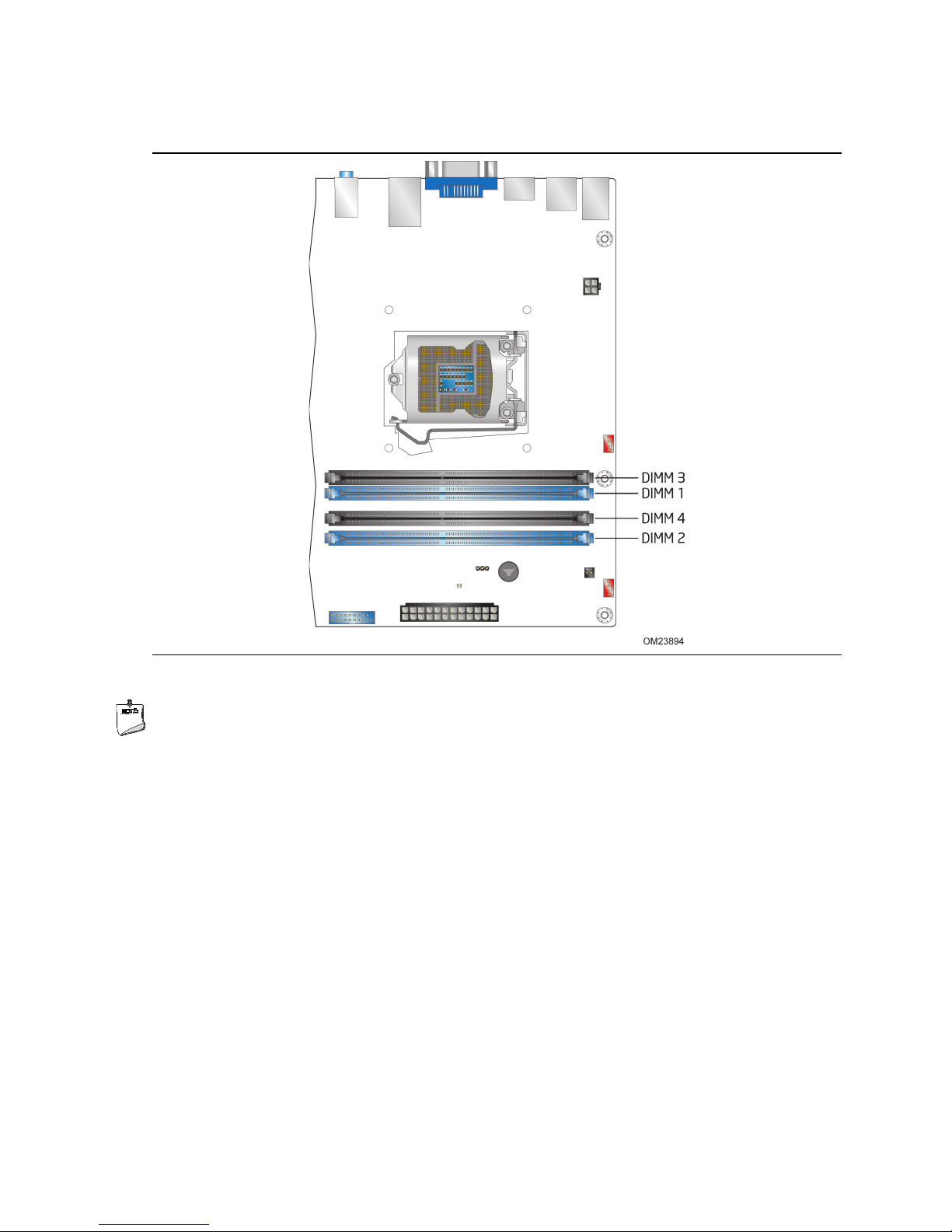
Figure 3 illustrates the memory channel and DIMM configuration.
Product Description
Figure 3. Memory Channel and DIMM Configuration
NOTE
For best memory performance always install memory in the blue DIMM sockets if
installing only two DIMMs on your board.
21

Intel Desktop Board DZ75ML-45K Technical Product Specification
1.5 Intel® Z75 Express Chipset
Intel Z75 Express Chipset with Intel Flexible Display Interconect (Intel FDI) and Direct
Media Interface (DMI) interconnect provides interfaces to the processor and the
display, USB, SATA, LPC, LAN, and PCI Express interfaces. The Intel Z75 Express
Chipset is a centralized controller for the board’s I/O paths.
For information about Refer to
The Intel Z75 chipset http://www.intel.com/products/desktop/chipsets/index.htm
Resources used by the chipset Chapter 2
1.5.1 Direct Media Interface (DMI)
Direct Media Interface (DMI) is the chip-to-chip connection between the processor and
PCH. This high-speed interface integrates advanced priority-based servicing allowing
for concurrent traffic and true isochronous transfer capabilities.
1.5.2 Display Interfaces
Display is divided between the processor and the PCH. The processor houses the
memory interface, display planes, and pipes while the PCH has transcoder and display
interface or ports.
The PCH receives the display data over Intel FDI and transcodes the data as per the
display technology protocol and sends the data through the display interface.
1.5.2.1 Intel
Intel FDI connects the display engine in the processor with the display interfaces on
the PCH. The display data from the frame buffer is processed in the display engine of
the processor and sent to the PCH over the Intel FDI where it is transcoded as per the
display protocol and driven to the display monitor.
®
Flexible Display Interconnect (Intel
®
FDI)
1.5.2.2 High-bandwidth Digital Content Protection (HDCP)
HDCP is the technology for protecting high definition content against unauthorized
copy or unreceptive between a source (computer, digital set top boxes, etc.) and the
sink (panels, monitor, and TVs). The PCH supports HDCP 1.4 for content protection
over wired displays (HDMI).
22
Product Description
No add-in card installed
Enabled
PCI Express x16 add-in card installed
Enabled
(Note)
No add-in card installed
Enabled
Enabled
PCI Express x16 add-in card installed
Enabled
(Note 2)
Enabled
(Note 2)
1.5.2.3 High Definition Multimedia Interface* (HDMI*)
The HDMI port supports standard, enhanced, or high definition video, plus multichannel digital audio on a single cable. It is compatible with all ATSC and DVB HDTV
standards and supports eight full range channels at 24-bit/96 kHz audio of lossless
audio formats such as Dolby* TrueHD or DTS* HD Master Audio. The maximum
supported resolution is 1920 x 1200 (WUXGA). The HDMI interface supports the
HDMI 1.4a specification.
Depending on the type of add-in card installed in the PCI Express x16 connector, the
HDMI port will behave as described in Table 4.
Table 4. HDMI Port Status Conditions
PCI Express x16 Connector Status HDMI Port Status
Note: May require BIOS setup menu changes.
1.5.2.4 Integrated Audio Provided by the HDMI Interface
The HDMI interface from the PCH supports audio. Table 5 shows the specific audio
technologies supported by the PCH.
Table 5. Audio Formats Supported by the HDMI Interface
Audio Formats HDMI 1.4a
AC-3 - Dolby* Digital Yes
Dolby Digital Plus Yes
DTS-HD* Yes
LPCM, 192 kHz/24 bit, 8 Channel Yes
1.5.2.5 Digital Visual Interface (DVI-I)
The DVI-I port supports both digital and analog DVI displays. The maximum
supported resolution is 1920 x 1200 (WUXGA). The DVI port is compliant with the
DVI 1.0 specification. DVI analog output can also be converted to VGA using a DVIVGA converter.
Depending on the type of add-in card installed in the PCI Express x16 connector, the
DVI port will behave as described in Table 6.
Table 6. DVI Port Status Conditions
PCI Express x16 Connector Status
DVI Digital (DVI-D)
Port Status
DVI Analog (DVI-A)
Port Status
(Note 1)
Notes:
1. DVI analog output can also be converted to VGA with a DVI-VGA converter.
2. May require BIOS setup menu changes.
23

Intel Desktop Board DZ75ML-45K Technical Product Specification
For information about
Refer to
1.5.3 USB
The PCH contains up to two Enhanced Host Controller Interface (EHCI) host controllers
that support USB high-speed signaling. High-speed USB 2.0 allows data transfers up to
480 Mb/s. All ports are high-speed, full-speed, and low-speed capable.
The PCH also contains an integrated eXtensible Host Controller Interface (xHCI) host
controller which supports USB 3.0 ports. This controller allows data transfers up to
5 Gb/s. The controller supports SuperSpeed (SS), high-speed (HS), full-speed (FS),
and low-speed (LS) traffic on the bus.
The Intel Z75 Express Chipset provides the USB controller for the 2.0/3.0 ports. The
port arrangement is as follows:
• Four USB 3.0 ports:
Two USB 3.0 ports are implemented with stacked back panel connectors (blue)
Two front panel USB 3.0 ports are implemented through one internal connector
(blue)
• Ten USB 2.0 ports:
Four ports implemented with stacked back panel
Six front panel ports are implemented through three dual-port internal headers
NOTE
Computer systems that have an unshielded cable attached to a USB port may not
meet FCC Class B requirements, even if no device is attached to the cable. Use a
shielded cable that meets the requirements for full-speed devices.
The location of the USB connectors on the back panel Figure 9, page 44
The location of the front panel USB headers Figure 10, page 45
1.5.4 SATA Interfaces
The board provides six SATA connectors, through the PCH, which support one device
each:
• Two internal SATA 6.0 Gb/s interfaces through the Intel Z75 Express Chipset with
• Four internal SATA 3.0 Gb/s interfaces through Intel Z75 Express Chipset with Intel
The PCH provides independent SATA ports with a theoretical maximum transfer rate of
6.0 Gb/s for two ports and 3.0 Gb/s for four ports. A point-to-point interface is used
for host to device connections.
The PCH supports the Serial ATA Specification, Revision 3.0. The PCH also supports
several optional sections of the Serial ATA II: Extensions to Serial ATA 1.0
Specification, Revision 1.0 (AHCI support is required for some elements).
®
Intel
Rapid Storage Technology RAID support (black)
Rapid Storage Technology RAID support (blue)
The underlying SATA functionality is transparent to the operating system. The SATA
controller can operate in both legacy and native modes. In legacy mode, standard IDE
24
Product Description
For information about
Refer to
I/O and IRQ resources are assigned (IRQ 14 and 15). Native mode is the preferred
mode for configurations using the Windows* XP and Windows 7 operating systems.
NOTE
Many SATA drives use new low-voltage power connectors and require adapters or
power supplies equipped with low-voltage power connectors.
For more information, see: http://www.serialata.org/.
The location of the SATA connectors Figure 10, page 45
1.5.4.1 SATA RAID
The board supports Intel Rapid Storage Technology which provides the following RAID
(Redundant Array of Independent Drives) levels via the Intel Z75 Express Chipset:
• RAID 0 - data striping
• RAID 1 - data mirroring
• RAID 0+1 (or RAID 10) - data striping and mirroring
• RAID 5 - distributed parity
1.5.4.2 Intel® Smart Response Technology
Intel® Smart Response Technology is a disk caching solution that can provide improved
computer system performance with improved power savings. It allows configuration of
a computer system with the advantage of having HDDs for maximum storage capacity
with system performance at or near SSD performance levels.
For more information on Intel Smart Response Technology, go to
http://www.intel.com/support/chipsets/sb/CS-032826.htm
NOTE
In order to use supported RAID and Intel Smart Response Technology features, you
must first enable RAID in the BIOS. Also, during Microsoft Windows XP installation, you
must press F6 to install the RAID drivers. See your Microsoft Windows XP
documentation for more information about installing drivers during installation.
Microsoft Windows 7 includes the necessary RAID drivers for both AHCI and RAID
without the need to install separate RAID drivers using the F6 switch in the operating
system installation process.
25

Intel Desktop Board DZ75ML-45K Technical Product Specification
1.6 Real-Time Clock Subsystem
A coin-cell battery (CR2032) powers the real-time clock and CMOS memory. When
the computer is not plugged into a wall socket, the battery has an estimated life of
three years. When the computer is plugged in, the standby current from the power
supply extends the life of the battery. The clock is accurate to ± 13 minutes/year at
25 ºC with 3.3 VSB applied via the power supply 5V STBY rail.
NOTE
If the battery and AC power fail, date and time values will be reset and the user will be
notified during the POST.
When the voltage drops below a certain level, the BIOS Setup program settings stored
in CMOS RAM (for example, the date and time) might not be accurate. Replace the
battery with an equivalent one. Figure 1 on page 13 shows the location of the battery.
1.7 Legacy I/O Controller
The I/O controller provides the following features:
• PS/2-style keyboard/mouse port
• Serial IRQ interface compatible with serialized IRQ support for PCI systems
• Intelligent power management, including a programmable wake-up event interface
• Fan Control
The BIOS Setup program provides configuration options for the I/O controller.
26
Product Description
Front panel – Green
Default
1.8 Audio Subsystem
The board supports the Intel® High Definition Audio (Intel® HD Audio) subsystem. The
audio subsystem consists of the following:
• Intel Z75 Express Chipset
• Realtek ALC662 audio codec
The audio subsystem has the following features:
• Advanced jack sense for the back panel audio jacks that enables the audio codec to
recognize the device that is connected to an audio port. The back panel audio
jacks are capable of retasking according to the user’s definition, or can be
automatically switched depending on the recognized device type.
• Front panel Intel HD Audio and AC ’97 audio support.
• 3-port analog audio out stack.
• A signal-to-noise (S/N) ratio of 95 dB.
• Windows Vista Ultimate and Windows 7 Ultimate certification.
Table 7 lists the supported functions of the front panel and back panel audio jacks.
Table 7. Audio Jack Support
Audio Jack
Front panel – Pink Default
Back panel – Blue Default
Back panel – Green (ctrl panel) Default
Back panel – Pink Default
Microphone Headphones
Line Out
(Front Spks)
Line In
(Surround)
1.8.1 Audio Subsystem Software
The latest audio software and drivers are available from Intel’s World Wide Web site.
For information about Refer to
Obtaining audio software and drivers Section 1.2, page 16
Mic-In
(Center/Sub)
27
 Loading...