


 Loading...
Intel® Xeon® Processor E5-1600/
E5-2600/E5-4600 Product Families
Datasheet - Volume One
May 2012
Reference Number: 326508, Revision: 002

INFORMATION IN THIS DOCUMENT IS PROVIDED IN CONNECTION WITH INTEL PRODUCTS. NO LICENSE, EXPRESS OR IMPLIED, BY ESTOPPEL OR OTHERWISE, TO ANY INTELLECTUAL PROPERTY RIGHTS IS GRANTED BY THIS DOCUMENT. EXCEPT AS PROVIDED IN INTEL'S TERMS AND CONDITIONS OF SALE FOR SUCH PRODUCTS, INTEL ASSUMES NO LIABILITY WHATSOEVER AND INTEL DISCLAIMS ANY EXPRESS OR IMPLIED WARRANTY, RELATING TO SALE AND/OR USE OF INTEL PRODUCTS INCLUDING LIABILITY OR WARRANTIES RELATING TO FITNESS FOR A PARTICULAR PURPOSE, MERCHANTABILITY, OR INFRINGEMENT OF ANY PATENT, COPYRIGHT OR OTHER INTELLECTUAL PROPERTY RIGHT.
UNLESS OTHERWISE AGREED IN WRITING BY INTEL, THE INTEL PRODUCTS ARE NOT DESIGNED NOR INTENDED FOR ANY APPLICATION IN WHICH THE FAILURE OF THE INTEL PRODUCT COULD CREATE A SITUATION WHERE PERSONAL INJURY OR DEATH MAY OCCUR.
Intel may make changes to specifications and product descriptions at any time, without notice. Designers must not rely on the absence or characteristics of any features or instructions marked "reserved" or "undefined." Intel reserves these for future definition and shall have no responsibility whatsoever for conflicts or incompatibilities arising from future changes to them. The information here is subject to change without notice. Do not finalize a design with this information.
The Intel® Xeon® Processor E5-1600/ E5-2600/E5-4600 Product Families, Intel® C600 series chipset, and the Intel® Xeon® Processor E5-1600/ E5-2600/E5-4600 Product Families-based Platform described in this document may contain design defects or errors known as errata which may cause the product to deviate from published specifications. Current characterized errata are available on request.
Contact your local Intel sales office or your distributor to obtain the latest specifications and before placing your product order.
Copies of documents which have an order number and are referenced in this document, or other Intel literature, may be obtained by calling 1-800-548-4725, or go to: http://www.intel.com/#/en_US_01
Hyper-Threading Technology requires a computer system with a processor supporting HT Technology and an HT Technology enabled chipset, BIOS and operating system. Performance will vary depending on the specific hardware and software you use. For more information including details on which processors support HT Technology, see http://www.intel.com/products/ht/hyperthreading_more.htm.
Enabling Execute Disable Bit functionality requires a PC with a processor with Execute Disable Bit capability and a supporting operating system. Check with your PC manufacturer on whether your system delivers Execute Disable Bit functionality.
Intel® Virtualization Technology requires a computer system with an enabled Intel® processor, BIOS, virtual machine monitor (VMM) and, for some uses, certain computer system software enabled for it. Functionality, performance or other benefits will vary depending on hardware and software configurations and may require a BIOS update. Software applications may not be compatible with all operating systems. Please check with your application vendor.
Intel® Turbo Boost Technology requires a PC with a processor with Intel Turbo Boost Technology capability. Intel Turbo Boost Technology performance varies depending on hardware, software and overall system configuration. Check with your PC manufacturer on whether your system delivers Intel Turbo Boost Technology. For more information, see http://www.intel.com/technology/turboboost/.
64-bit computing on Intel architecture requires a computer system with a processor, chipset, BIOS, operating system, device drivers and applications enabled for Intel® 64 architecture. Performance will vary depending on your hardware and software configurations. Consult with your system vendor for more information.
Intel processor numbers are not a measure of performance. Processor numbers differentiate features within each processor family, not across different processor families. See http://www.intel.com/products/processor%5Fnumber/ for details.
I2C is a two-wire communications bus/protocol developed by Philips. SMBus is a subset of the I2C bus/protocol and was developed by Intel. Implementations of the I2C bus/protocol may require licenses from various entities, including Philips Electronics N.V. and North American Philips Corporation.
Intel, Xeon, Intel SpeedStep, Intel Core, and the Intel logo are trademarks of Intel Corporation in the U. S. and other countries. *Other names and brands may be claimed as the property of others.
Copyright © 2009-2012, Intel Corporation. All rights reserved.
2 |
Intel® Xeon® Processor E5-1600/ E5-2600/E5-4600 Product Families |
|
Datasheet Volume One |

Contents
1 |
Overview ................................................................................................................. |
|
13 |
|
|
1.1 |
Introduction ..................................................................................................... |
13 |
|
|
|
1.1.1 |
Processor Feature Details ........................................................................ |
14 |
|
|
1.1.2 |
Supported Technologies .......................................................................... |
14 |
|
1.2 |
Interfaces ........................................................................................................ |
15 |
|
|
|
1.2.1 |
System Memory Support ......................................................................... |
15 |
|
|
1.2.2 |
PCI Express* ......................................................................................... |
16 |
|
|
1.2.3 Direct Media Interface Gen 2 (DMI2)......................................................... |
17 |
|
|
|
1.2.4 Intel® QuickPath Interconnect (Intel® QPI) .............................................. |
18 |
|
|
|
1.2.5 Platform Environment Control Interface (PECI)........................................... |
18 |
|
|
1.3 |
Power Management Support ............................................................................... |
19 |
|
|
|
1.3.1 Processor Package and Core States........................................................... |
19 |
|
|
|
1.3.2 |
System States Support ........................................................................... |
19 |
|
|
1.3.3 |
Memory Controller.................................................................................. |
19 |
|
|
1.3.4 |
PCI Express........................................................................................... |
19 |
|
|
1.3.5 |
Intel QPI ............................................................................................... |
19 |
|
1.4 |
Thermal Management Support ............................................................................ |
19 |
|
|
1.5 |
Package Summary............................................................................................. |
20 |
|
|
1.6 |
Terminology ..................................................................................................... |
20 |
|
|
1.7 |
Related Documents ........................................................................................... |
22 |
|
|
1.8 |
State of Data .................................................................................................... |
23 |
|
2 |
Interfaces................................................................................................................ |
|
25 |
|
|
2.1 |
System Memory Interface .................................................................................. |
25 |
|
|
|
2.1.1 System Memory Technology Support ........................................................ |
25 |
|
|
|
2.1.2 System Memory Timing Support............................................................... |
25 |
|
|
2.2 |
PCI Express* Interface....................................................................................... |
26 |
|
|
|
2.2.1 |
PCI Express* Architecture ....................................................................... |
26 |
|
|
2.2.2 PCI Express* Configuration Mechanism ..................................................... |
27 |
|
|
2.3 |
DMI2/PCI Express* Interface .............................................................................. |
28 |
|
|
|
2.3.1 |
DMI2 Error Flow..................................................................................... |
28 |
|
|
2.3.2 |
Processor/PCH Compatibility Assumptions.................................................. |
28 |
|
|
2.3.3 |
DMI2 Link Down..................................................................................... |
28 |
|
2.4 |
Intel QuickPath Interconnect............................................................................... |
28 |
|
|
2.5 |
Platform Environment Control Interface (PECI)...................................................... |
30 |
|
|
|
2.5.1 |
PECI Client Capabilities ........................................................................... |
30 |
|
|
2.5.2 |
Client Command Suite ............................................................................ |
31 |
|
|
2.5.3 |
Client Management................................................................................. |
69 |
|
|
2.5.4 |
Multi-Domain Commands ........................................................................ |
74 |
|
|
2.5.5 |
Client Responses.................................................................................... |
75 |
|
|
2.5.6 |
Originator Responses.............................................................................. |
76 |
|
|
2.5.7 |
DTS Temperature Data ........................................................................... |
76 |
3 |
Technologies ........................................................................................................... |
79 |
||
|
3.1 |
Intel® Virtualization Technology (Intel® VT) ........................................................ |
79 |
|
|
|
3.1.1 |
Intel VT-x Objectives .............................................................................. |
79 |
|
|
3.1.2 |
Intel VT-x Features................................................................................. |
80 |
|
|
3.1.3 |
Intel VT-d Objectives .............................................................................. |
80 |
|
|
3.1.4 Intel Virtualization Technology Processor Extensions ................................... |
81 |
|
|
3.2 |
Security Technologies ........................................................................................ |
81 |
|
|
|
3.2.1 Intel® Trusted Execution Technology........................................................ |
81 |
|
|
|
3.2.2 Intel Trusted Execution Technology – Server Extensions.............................. |
82 |
|
|
|
3.2.3 Intel® Advanced Encryption Standard Instructions (Intel® AES-NI).............. |
82 |
|
Intel® Xeon® Processor E5-1600/ E5-2600/E5-4600 Product Families |
3 |
Datasheet Volume One |
|

|
|
|
3.2.4 |
.................................................................................Execute Disable Bit |
83 |
|
3.3 |
Intel® Hyper-Threading Technology..................................................................... |
83 |
||
|
3.4 |
Intel® Turbo Boost Technology ........................................................................... |
83 |
||
|
|
|
3.4.1 Intel® Turbo Boost Operating Frequency ................................................... |
83 |
|
|
3.5 |
Enhanced Intel SpeedStep® Technology............................................................... |
84 |
||
|
3.6 |
Intel® Intelligent Power Technology..................................................................... |
84 |
||
|
3.7 |
Intel® Advanced Vector Extensions (Intel® AVX) .................................................. |
84 |
||
|
3.8 |
Intel Dynamic Power Technology ......................................................................... |
85 |
||
4 |
|
Power Management ................................................................................................. |
87 |
||
|
4.1 |
ACPI States Supported ....................................................................................... |
87 |
||
|
|
|
4.1.1 |
System States........................................................................................ |
87 |
|
|
|
4.1.2 Processor Package and Core States ........................................................... |
87 |
|
|
|
|
4.1.3 Integrated Memory Controller States......................................................... |
88 |
|
|
|
|
4.1.4 DMI2/PCI Express* Link States................................................................. |
89 |
|
|
|
|
4.1.5 Intel QuickPath Interconnect States .......................................................... |
89 |
|
|
|
|
4.1.6 G, S, and C State Combinations................................................................ |
90 |
|
|
4.2 |
Processor Core/Package Power Management ......................................................... |
90 |
||
|
|
|
4.2.1 Enhanced Intel SpeedStep Technology....................................................... |
90 |
|
|
|
|
4.2.2 |
Low-Power Idle States............................................................................. |
91 |
|
|
|
4.2.3 Requesting Low-Power Idle States ............................................................ |
92 |
|
|
|
|
4.2.4 |
Core C-states ......................................................................................... |
92 |
|
|
|
4.2.5 |
Package C-States ................................................................................... |
94 |
|
|
|
4.2.6 Package C-State Power Specifications........................................................ |
97 |
|
|
4.3 |
System Memory Power Management .................................................................... |
98 |
||
|
|
|
4.3.1 |
CKE Power-Down.................................................................................... |
98 |
|
|
|
4.3.2 |
Self Refresh ........................................................................................... |
98 |
|
|
|
4.3.3 DRAM I/O Power Management.................................................................. |
99 |
|
|
4.4 |
DMI2/PCI Express* Power Management................................................................ |
99 |
||
5 |
|
Thermal Management Specifications ...................................................................... |
101 |
||
|
5.1 |
Package Thermal Specifications ......................................................................... |
101 |
||
|
|
|
5.1.1 |
Thermal Specifications........................................................................... |
101 |
|
|
|
5.1.2 TCASE and DTS Based Thermal Specifications........................................... |
103 |
|
|
|
|
5.1.3 |
Processor Thermal Profiles ..................................................................... |
104 |
|
|
|
5.1.4 Embedded Server Processor Thermal Profiles............................................ |
130 |
|
|
|
|
5.1.5 |
Thermal Metrology................................................................................ |
133 |
|
5.2 |
Processor Core Thermal Features ....................................................................... |
135 |
||
|
|
|
5.2.1 |
Processor Temperature.......................................................................... |
135 |
|
|
|
5.2.2 |
Adaptive Thermal Monitor ...................................................................... |
135 |
|
|
|
5.2.3 |
On-Demand Mode................................................................................. |
137 |
|
|
|
5.2.4 |
PROCHOT_N Signal ............................................................................... |
137 |
|
|
|
5.2.5 |
THERMTRIP_N Signal ............................................................................ |
138 |
|
|
|
5.2.6 Integrated Memory Controller (IMC) Thermal Features............................... |
138 |
|
6 |
|
Signal Descriptions ................................................................................................ |
141 |
||
|
6.1 |
System Memory Interface Signals ...................................................................... |
141 |
||
|
6.2 |
PCI Express* Based Interface Signals ................................................................. |
142 |
||
|
6.3 |
DMI2/PCI Express* Port 0 Signals...................................................................... |
144 |
||
|
6.4 |
Intel QuickPath Interconnect Signals .................................................................. |
144 |
||
|
6.5 |
PECI Signal..................................................................................................... |
145 |
||
|
6.6 |
System Reference Clock Signals ........................................................................ |
145 |
||
|
6.7 |
JTAG and TAP Signals....................................................................................... |
145 |
||
|
6.8 |
Serial VID Interface (SVID) Signals .................................................................... |
146 |
||
|
6.9 |
Processor Asynchronous Sideband and Miscellaneous Signals................................. |
146 |
||
|
6.10 |
Processor Power and Ground Supplies ................................................................ |
149 |
||
4 |
Intel® Xeon® Processor E5-1600/ E5-2600/E5-4600 Product Families |
|
Datasheet Volume One |

7 |
Electrical Specifications......................................................................................... |
|
|
151 |
||
|
7.1 |
Processor Signaling ......................................................................................... |
151 |
|||
|
|
7.1.1 |
System Memory Interface Signal Groups ................................................. |
151 |
||
|
|
7.1.2 |
PCI Express* Signals ............................................................................ |
151 |
||
|
|
7.1.3 |
DMI2/PCI Express* Signals.................................................................... |
151 |
||
|
|
7.1.4 |
Intel QuickPath Interconnect (Intel QPI).................................................. |
151 |
||
|
|
7.1.5 |
Platform Environmental Control Interface (PECI) ...................................... |
152 |
||
|
|
7.1.6 |
System Reference Clocks (BCLK{0/1}_DP, BCLK{0/1}_DN)....................... |
152 |
||
|
|
7.1.7 |
JTAG and Test Access Port (TAP) Signals ................................................. |
153 |
||
|
|
7.1.8 |
Processor Sideband Signals ................................................................... |
153 |
||
|
|
7.1.9 |
Power, Ground and Sense Signals........................................................... |
153 |
||
|
|
7.1.10 |
Reserved or Unused Signals................................................................... |
158 |
||
|
7.2 |
Signal Group Summary .................................................................................... |
158 |
|||
|
7.3 |
Power-On Configuration (POC) Options............................................................... |
162 |
|||
|
7.4 |
Fault Resilient Booting (FRB)............................................................................. |
163 |
|||
|
7.5 |
Mixing Processors............................................................................................ |
163 |
|||
|
7.6 |
Flexible Motherboard Guidelines (FMB)............................................................... |
164 |
|||
|
7.7 |
Absolute Maximum and Minimum Ratings ........................................................... |
164 |
|||
|
|
7.7.1 |
Storage Conditions Specifications ........................................................... |
165 |
||
|
7.8 |
DC Specifications ............................................................................................ |
166 |
|||
|
|
7.8.1 |
Voltage and Current Specifications.......................................................... |
167 |
||
|
|
7.8.2 |
Die Voltage Validation........................................................................... |
173 |
||
|
|
7.8.3 |
Signal DC Specifications ........................................................................ |
174 |
||
|
7.9 |
Waveforms..................................................................................................... |
180 |
|||
|
7.10 |
Signal Quality ................................................................................................. |
181 |
|||
|
|
7.10.1 |
DDR3 Signal Quality Specifications ......................................................... |
182 |
||
|
|
7.10.2 |
I/O Signal Quality Specifications............................................................. |
182 |
||
|
|
7.10.3 |
Intel QuickPath Interconnect Signal Quality Specifications.......................... |
182 |
||
|
|
7.10.4 |
Input Reference Clock Signal Quality Specifications................................... |
182 |
||
|
|
7.10.5 |
Overshoot/Undershoot Tolerance............................................................ |
182 |
||
8 |
Processor Land Listing........................................................................................... |
187 |
||||
|
8.1 |
Listing by Land Name ...................................................................................... |
187 |
|||
|
8.2 |
Listing by Land Number ................................................................................... |
212 |
|||
9 |
Package Mechanical Specifications ........................................................................ |
237 |
||||
|
9.1 |
Package Mechanical Drawing............................................................................. |
237 |
|||
|
9.2 |
Processor Component Keep-Out Zones............................................................... |
241 |
|||
|
9.3 |
Package Loading Specifications ......................................................................... |
241 |
|||
|
9.4 |
Package Handling Guidelines............................................................................. |
241 |
|||
|
9.5 |
Package Insertion Specifications........................................................................ |
241 |
|||
|
9.6 |
Processor Mass Specification............................................................................. |
242 |
|||
|
9.7 |
Processor Materials.......................................................................................... |
242 |
|||
|
9.8 |
Processor Markings.......................................................................................... |
242 |
|||
10 |
Boxed Processor Specifications ............................................................................. |
243 |
||||
|
10.1 |
Introduction ................................................................................................... |
243 |
|||
|
|
10.1.1 |
Available Boxed Thermal Solution Configurations ...................................... |
243 |
||
|
|
10.1.2 |
Intel Thermal Solution STS200C |
|
||
|
|
|
(Passive/Active Combination Heat Sink Solution) ...................................... |
243 |
||
|
|
10.1.3 |
Intel Thermal Solution STS200P and STS200PNRW |
|
||
|
|
|
(Boxed 25.5 mm Tall Passive Heat Sink Solutions).................................... |
244 |
||
|
10.2 |
Mechanical Specifications ................................................................................. |
245 |
|||
|
|
10.2.1 |
Boxed Processor Heat Sink Dimensions and Baseboard Keepout Zones ........ |
245 |
||
|
|
10.2.2 |
Boxed Processor Retention Mechanism and Heat Sink Support (ILM-RS) ...... |
254 |
||
|
10.3 |
Fan Power Supply [STS200C]............................................................................ |
254 |
|||
|
|
10.3.1 |
Boxed Processor Cooling Requirements ................................................... |
255 |
||
|
10.4 |
Boxed Processor Contents ................................................................................ |
257 |
|||
Intel® Xeon® Processor E5-1600/ E5-2600/E5-4600 Product Families |
5 |
Datasheet Volume One |
|

Figures
1-1 |
Intel® Xeon® Processor E5-2600 Product Family on the 2 Socket |
|
|
Platform ........................................................................................................... |
14 |
1-2 |
PCI Express* Lane Partitioning and Direct Media Interface Gen 2 (DMI2)................... |
17 |
2-1 |
PCI Express* Layering Diagram ........................................................................... |
26 |
2-2 |
Packet Flow through the Layers ........................................................................... |
27 |
2-3 |
Ping() .............................................................................................................. |
32 |
2-4 |
Ping() Example.................................................................................................. |
32 |
2-5 |
GetDIB() .......................................................................................................... |
32 |
2-6 |
Device Info Field Definition ................................................................................. |
33 |
2-7 |
Revision Number Definition ................................................................................. |
33 |
2-8 |
GetTemp()........................................................................................................ |
34 |
2-9 |
GetTemp() Example ........................................................................................... |
35 |
2-10 |
RdPkgConfig() ................................................................................................... |
36 |
2-11 |
WrPkgConfig()................................................................................................... |
37 |
2-12 |
DRAM Thermal Estimation Configuration Data........................................................ |
40 |
2-13 |
DRAM Rank Temperature Write Data .................................................................... |
41 |
2-14 |
The Processor DIMM Temperature Read / Write ..................................................... |
42 |
2-15 |
Ambient Temperature Reference Data .................................................................. |
42 |
2-16 |
Processor DRAM Channel Temperature ................................................................. |
43 |
2-17 |
Accumulated DRAM Energy Data.......................................................................... |
43 |
2-18 |
DRAM Power Info Read Data ............................................................................... |
44 |
2-19 |
DRAM Power Limit Data ...................................................................................... |
45 |
2-20 |
DRAM Power Limit Performance Data.................................................................... |
45 |
2-21 |
CPUID Data ...................................................................................................... |
49 |
2-22 |
Platform ID Data ............................................................................................... |
49 |
2-23 |
PCU Device ID................................................................................................... |
49 |
2-24 |
Maximum Thread ID........................................................................................... |
50 |
2-25 |
Processor Microcode Revision .............................................................................. |
50 |
2-26 |
Machine Check Status ........................................................................................ |
50 |
2-27 |
Package Power SKU Unit Data ............................................................................. |
50 |
2-28 |
Package Power SKU Data.................................................................................... |
52 |
2-29 |
Package Temperature Read Data ......................................................................... |
52 |
2-30 |
Temperature Target Read ................................................................................... |
53 |
2-31 |
Thermal Status Word ......................................................................................... |
54 |
2-32 |
Thermal Averaging Constant Write / Read ............................................................. |
54 |
2-33 |
Current Config Limit Read Data ........................................................................... |
55 |
2-34 |
Accumulated Energy Read Data ........................................................................... |
55 |
2-35 |
Power Limit Data for VCC Power Plane .................................................................. |
56 |
2-36 |
Package Turbo Power Limit Data.......................................................................... |
57 |
2-37 |
Package Power Limit Performance Data ................................................................ |
57 |
2-38 |
Efficient Performance Indicator Read .................................................................... |
58 |
2-39 |
ACPI P-T Notify Data .......................................................................................... |
58 |
2-40 |
Caching Agent TOR Read Data............................................................................. |
59 |
2-41 |
DTS Thermal Margin Read................................................................................... |
59 |
2-42 |
Processor ID Construction Example ...................................................................... |
61 |
2-43 |
RdIAMSR()........................................................................................................ |
61 |
2-44 |
PCI Configuration Address................................................................................... |
64 |
2-45 |
RdPCIConfig() ................................................................................................... |
64 |
2-46 |
PCI Configuration Address for local accesses.......................................................... |
66 |
6 |
Intel® Xeon® Processor E5-1600/ E5-2600/E5-4600 Product Families |
|
Datasheet Volume One |

2-47 |
RdPCIConfigLocal()............................................................................................ |
|
|
66 |
2-48 |
WrPCIConfigLocal() ........................................................................................... |
68 |
||
2-49 |
The Processor PECI Power-up Timeline() .............................................................. |
70 |
||
2-50 |
Temperature Sensor Data Format........................................................................ |
76 |
||
4-1 |
Idle Power Management Breakdown of the Processor Cores..................................... |
91 |
||
4-2 |
Thread and Core C-State Entry and Exit ............................................................... |
91 |
||
4-3 |
Package C-State Entry and Exit ........................................................................... |
95 |
||
5-1 |
Tcase: 8-Core 150W Thermal Profile, Workstation Platform SKU Only ..................... |
105 |
||
5-2 |
DTS: 8-Core 150W Thermal Profile, Workstation Platform SKU Only ....................... |
105 |
||
5-3 |
Tcase: 8-Core 135W Thermal Profile 2U ............................................................. |
107 |
||
5-4 |
DTS: 8-Core 135W Thermal Profile 2U................................................................ |
108 |
||
5-5 |
Tcase: 8/6-Core 130W Thermal Profile 1U .......................................................... |
110 |
||
5-6 |
DTS: 8-Core 130W Thermal Profile 1U................................................................ |
110 |
||
5-7 |
DTS: 6-Core 130W Thermal Profile 1U................................................................ |
111 |
||
5-8 |
Tcase: 6-Core 130W 1S WS Thermal Profile ........................................................ |
112 |
||
5-9 |
DTS: 6-Core 130W 1S WS Thermal Profile .......................................................... |
113 |
||
5-10 |
Tcase: 8-Core 115W Thermal Profile 1U ............................................................. |
115 |
||
5-11 |
DTS: 8-Core 115W Thermal Profile 1U................................................................ |
115 |
||
5-12 |
Tcase: 8/6-Core 95W Thermal Profile 1U ............................................................ |
117 |
||
5-13 |
DTS: 8-Core 95W Thermal Profile 1U ................................................................. |
117 |
||
5-14 |
DTS: 6-Core 95W Thermal Profile 1U ................................................................. |
118 |
||
5-15 |
Tcase: 8-Core 70W Thermal Profile 1U ............................................................... |
119 |
||
5-16 |
DTS: 8-Core 70W Thermal Profile 1U ................................................................. |
120 |
||
5-17 |
Tcase: 6-Core 60W Thermal Profile 1U ............................................................... |
121 |
||
5-18 |
DTS: 6-Core 60W Thermal Profile 1U ................................................................. |
122 |
||
5-19 |
Tcase: 4-Core 130W Thermal Profile 2U ............................................................. |
123 |
||
5-20 |
DTS: 4-Core 130W Thermal Profile 2U................................................................ |
124 |
||
5-21 |
Tcase: 4-Core 130W 1S WS Thermal Profile ........................................................ |
126 |
||
5-22 |
DTS: 4-Core 130W 1S WS Thermal Profile .......................................................... |
126 |
||
5-23 |
Tcase: 4/2-Core 80W Thermal Profile 1U ............................................................ |
128 |
||
5-24 |
DTS: 4-Core 80W Thermal Profile 1U ................................................................. |
128 |
||
5-25 |
DTS: 2-Core 80W Thermal Profile 1U ................................................................. |
129 |
||
5-26 |
Tcase: 8-Core LV95W Thermal Profile, Embedded Server SKU ............................... |
131 |
||
5-27 |
Tcase: 8-Core LV70W Thermal Profile, Embedded Server SKU ............................... |
132 |
||
5-28 |
Case Temperature (TCASE) Measurement Location .............................................. |
134 |
||
5-29 |
Frequency and Voltage Ordering........................................................................ |
136 |
||
7-1 |
Input Device Hysteresis ................................................................................... |
152 |
||
7-2 |
VR Power-State Transitions............................................................................... |
156 |
||
7-3 |
8/6-Core: VCC Static and Transient Tolerance Loadlines ....................................... |
170 |
||
7-4 |
4/2-Core: Processor VCC Static and Transient Tolerance Loadlines......................... |
172 |
||
7-5 |
Load Current Versus Time ................................................................................ |
173 |
||
7-6 |
VCC Overshoot Example Waveform.................................................................... |
174 |
||
7-7 |
BCLK{0/1} Differential Clock Crosspoint Specification .......................................... |
180 |
||
7-8 |
BCLK{0/1} Differential Clock Measurement Point for Ringback .............................. |
180 |
||
7-9 |
BCLK{0/1} Single Ended Clock Measurement Points for Absolute Cross Point |
|
||
|
and Swing ...................................................................................................... |
181 |
||
7-10 |
BCLK{0/1} Single Ended Clock Measurement Points for Delta Cross Point ............... |
181 |
||
7-11 |
Maximum Acceptable Overshoot/Undershoot Waveform........................................ |
185 |
||
9-1 |
Processor Package Assembly Sketch .................................................................. |
237 |
||
9-2 |
Processor Package Drawing Sheet 1 of 2 ............................................................ |
239 |
||
9-3 |
Processor Package Drawing Sheet 2 of 2 ............................................................ |
240 |
||
9-4 |
Processor Top-Side Markings ........................................................................... |
242 |
||
Intel® Xeon® Processor E5-1600/ E5-2600/E5-4600 Product Families |
7 |
Datasheet Volume One |
|

|
10-1 |
...................STS200C Passive/Active Combination Heat Sink (with Removable Fan) |
244 |
10-2 |
STS200C Passive/Active Combination Heat Sink (with Fan Removed)...................... |
244 |
|
10-3 |
STS200P and STS200PNRW 25.5 mm Tall Passive Heat Sinks ................................ |
245 |
|
10-4 |
Boxed Processor Motherboard Keepout Zones (1 of 4) .......................................... |
246 |
|
10-5 |
Boxed Processor Motherboard Keepout Zones (2 of 4) .......................................... |
247 |
|
10-6 |
Boxed Processor Motherboard Keepout Zones (3 of 4) .......................................... |
248 |
|
10-7 |
Boxed Processor Motherboard Keepout Zones (4 of 4) .......................................... |
249 |
|
10-8 |
Boxed Processor Heat Sink Volumetric (1 of 2) .................................................... |
250 |
|
10-9 |
Boxed Processor Heat Sink Volumetric (2 of 2) .................................................... |
251 |
|
10-10 |
4-Pin Fan Cable Connector (For Active Heat Sink) ................................................ |
252 |
|
10-11 |
4-Pin Base Baseboard Fan Header (For Active Heat Sink) ..................................... |
253 |
|
10-12 |
Fan Cable Connector Pin Out For 4-Pin Active Thermal Solution............................. |
255 |
|
Tables
1-1 |
Referenced Documents....................................................................................... |
22 |
2-1 |
Summary of Processor-specific PECI Commands .................................................... |
30 |
2-2 |
Minor Revision Number Meaning .......................................................................... |
33 |
2-3 |
GetTemp() Response Definition ........................................................................... |
35 |
2-4 |
RdPkgConfig() Response Definition....................................................................... |
36 |
2-5 |
WrPkgConfig() Response Definition ...................................................................... |
37 |
2-6 |
RdPkgConfig() & WrPkgConfig() DRAM Thermal and Power Optimization |
|
|
Services Summary............................................................................................. |
39 |
2-7 |
Channel & DIMM Index Decoding ......................................................................... |
41 |
2-8 |
RdPkgConfig() & WrPkgConfig() CPU Thermal and Power Optimization |
|
|
Services Summary............................................................................................. |
46 |
2-9 |
Power Control Register Unit Calculations ............................................................... |
51 |
2-10 |
RdIAMSR() Response Definition ........................................................................... |
62 |
2-11 |
RdIAMSR() Services Summary............................................................................. |
62 |
2-12 |
RdPCIConfig() Response Definition....................................................................... |
65 |
2-13 |
RdPCIConfigLocal() Response Definition................................................................ |
67 |
2-14 |
WrPCIConfigLocal() Response Definition................................................................ |
68 |
2-15 |
WrPCIConfigLocal() Memory Controller and IIO Device/Function Support................... |
69 |
2-16 |
PECI Client Response During Power-Up................................................................. |
69 |
2-17 |
SOCKET ID Strapping......................................................................................... |
71 |
2-18 |
Power Impact of PECI Commands vs. C-states....................................................... |
71 |
2-19 |
Domain ID Definition.......................................................................................... |
74 |
2-20 |
Multi-Domain Command Code Reference............................................................... |
74 |
2-21 |
Completion Code Pass/Fail Mask .......................................................................... |
75 |
2-22 |
Device Specific Completion Code (CC) Definition .................................................... |
75 |
2-23 |
Originator Response Guidelines............................................................................ |
76 |
2-24 |
Error Codes and Descriptions............................................................................... |
77 |
4-1 |
System States................................................................................................... |
87 |
4-2 |
Package C-State Support .................................................................................... |
87 |
4-3 |
Core C-State Support ......................................................................................... |
88 |
4-4 |
System Memory Power States ............................................................................. |
88 |
4-5 |
DMI2/PCI Express* Link States............................................................................ |
89 |
4-6 |
Intel QPI States................................................................................................. |
89 |
4-7 |
G, S and C State Combinations............................................................................ |
90 |
4-8 |
P_LVLx to MWAIT Conversion .............................................................................. |
92 |
4-9 |
Coordination of Core Power States at the Package Level.......................................... |
95 |
8 |
Intel® Xeon® Processor E5-1600/ E5-2600/E5-4600 Product Families |
|
Datasheet Volume One |

4-10 |
Package C-State Power Specifications .................................................................. |
|
|
97 |
5-1 |
Processor SKU Summary Table ......................................................................... |
104 |
||
5-2 |
Tcase: 8-Core 150W Thermal Specifications, Workstation Platform SKU Only........... |
104 |
||
5-3 |
8-Core 150W Thermal Profile, Workstation Platform SKU Only ............................. |
106 |
||
5-4 |
Tcase: 8-Core 135W Thermal Specifications 2U ................................................... |
107 |
||
5-5 |
8-Core 135W Thermal Profile Table 2U ............................................................... |
108 |
||
5-6 |
Tcase: 8/6-Core 130W Thermal Specifications, Workstation/Server Platform ........... |
109 |
||
5-7 |
8/6-Core 130W Thermal Profile Table 1U ............................................................ |
111 |
||
5-8 |
Tcase: 6-Core 130W 1S WS Thermal Specifications.............................................. |
112 |
||
5-9 |
6-Core 130W 1S WS Thermal Profile Table.......................................................... |
113 |
||
5-10 |
Tcase: 8-Core 115W Thermal Specifications 1U ................................................... |
114 |
||
5-11 |
8-Core 115W Thermal Profile Table 1U ............................................................... |
116 |
||
5-12 |
Tcase: 8/6-Core 95W Thermal Specifications, Workstation/Server Platform ............. |
116 |
||
5-13 |
8/6-Core 95W Thermal Profile Table 1U.............................................................. |
118 |
||
5-14 |
Tcase: 8-Core 70W Thermal Specifications 1U..................................................... |
119 |
||
5-15 |
8-Core 70W Thermal Profile Table 1U................................................................. |
120 |
||
5-16 |
Tcase: 6-Core 60W Thermal Specifications 1U..................................................... |
121 |
||
5-17 |
6-Core 60W Thermal Profile Table 1U................................................................. |
122 |
||
5-18 |
Tcase: 4-Core 130W Thermal Specifications 2U ................................................... |
123 |
||
5-19 |
4-Core 130W Thermal Profile Table 2U ............................................................... |
124 |
||
5-20 |
Tcase: 4-Core 130W 1S WS Thermal Specifications, Workstation/Server Platform .... |
125 |
||
5-21 |
4-Core 130W 1S WS Thermal Profile Table.......................................................... |
127 |
||
5-22 |
Tcase: 4/2-Core 80W Thermal Specifications 1U.................................................. |
127 |
||
5-23 |
4/2-Core 80W Thermal Profile Table 1U.............................................................. |
129 |
||
5-24 |
Embedded Server Processor Elevated Tcase SKU Summary Table .......................... |
130 |
||
5-25 |
Tcase: 8-Core LV95W Thermal Specifications, Embedded Server SKU..................... |
130 |
||
5-26 |
8-Core LV95W Thermal Profile Table, Embedded Server SKU................................. |
131 |
||
5-27 |
Tcase: 8-Core LV70W Thermal Specifications, Embedded Server SKU..................... |
132 |
||
5-28 |
8-Core LV70W Thermal Profile Table, Embedded Server SKU................................. |
133 |
||
6-1 |
Memory Channel DDR0, DDR1, DDR2, DDR3....................................................... |
141 |
||
6-2 |
Memory Channel Miscellaneous ......................................................................... |
142 |
||
6-3 |
PCI Express* Port 1 Signals .............................................................................. |
142 |
||
6-4 |
PCI Express* Port 2 Signals .............................................................................. |
142 |
||
6-5 |
PCI Express* Port 3 Signals .............................................................................. |
143 |
||
6-6 |
PCI Express* Miscellaneous Signals ................................................................... |
143 |
||
6-7 |
DMI2 and PCI Express* Port 0 Signals................................................................ |
144 |
||
6-8 |
Intel QPI Port 0 and 1 Signals ........................................................................... |
144 |
||
6-9 |
Intel QPI Miscellaneous Signals ......................................................................... |
144 |
||
6-10 |
PECI Signals ................................................................................................... |
145 |
||
6-11 |
System Reference Clock (BCLK{0/1}) Signals ..................................................... |
145 |
||
6-12 |
JTAG and TAP Signals ...................................................................................... |
145 |
||
6-13 |
SVID Signals .................................................................................................. |
146 |
||
6-14 |
Processor Asynchronous Sideband Signals .......................................................... |
146 |
||
6-15 |
Miscellaneous Signals ...................................................................................... |
148 |
||
6-16 |
Power and Ground Signals................................................................................ |
149 |
||
7-1 |
Power and Ground Lands.................................................................................. |
154 |
||
7-2 |
SVID Address Usage ........................................................................................ |
157 |
||
7-3 |
VR12.0 Reference Code Voltage Identification (VID) Table .................................... |
157 |
||
7-4 |
Signal Description Buffer Types ......................................................................... |
158 |
||
7-5 |
Signal Groups ................................................................................................. |
159 |
||
7-6 |
Signals with On-Die Termination ....................................................................... |
162 |
||
7-7 |
Power-On Configuration Option Lands ................................................................ |
162 |
||
Intel® Xeon® Processor E5-1600/ E5-2600/E5-4600 Product Families |
9 |
Datasheet Volume One |
|

|
7-8 |
.................................................Fault Resilient Booting (Output Tri-State) Signals |
163 |
7-9 |
Processor Absolute Minimum and Maximum Ratings ............................................. |
164 |
|
7-10 |
Storage Condition Ratings................................................................................. |
165 |
|
7-11 |
Voltage Specification ........................................................................................ |
167 |
|
7-12 |
Processor Current Specifications ........................................................................ |
168 |
|
7-13 |
8/6 Core: Processor VCC Static and Transient Tolerance ....................................... |
169 |
|
7-14 |
4/2-Core: Processor VCC Static and Transient Tolerance ....................................... |
170 |
|
7-15 |
VCC Overshoot Specifications ............................................................................ |
173 |
|
7-16 |
DDR3 and DDR3L Signal DC Specifications .......................................................... |
174 |
|
7-17 |
PECI DC Specifications ..................................................................................... |
176 |
|
7-18 |
System Reference Clock (BCLK{0/1}) DC Specifications........................................ |
176 |
|
7-19 |
SMBus DC Specifications................................................................................... |
176 |
|
7-20 |
JTAG and TAP Signals DC Specifications.............................................................. |
177 |
|
7-21 |
Serial VID Interface (SVID) DC Specifications ...................................................... |
177 |
|
7-22 |
Processor Asynchronous Sideband DC Specifications............................................. |
178 |
|
7-23 |
Miscellaneous Signals DC Specifications .............................................................. |
179 |
|
7-24 |
Processor I/O Overshoot/Undershoot Specifications.............................................. |
182 |
|
7-25 |
Processor Sideband Signal Group Overshoot/Undershoot Tolerance ........................ |
184 |
|
8-1 |
Land Name ..................................................................................................... |
187 |
|
8-2 |
Land Number .................................................................................................. |
212 |
|
9-1 |
Processor Loading Specifications ........................................................................ |
241 |
|
9-2 |
Package Handling Guidelines ............................................................................. |
241 |
|
9-3 |
Processor Materials .......................................................................................... |
242 |
|
10-1 |
PWM Fan Frequency Specifications For 4-Pin Active Thermal Solution...................... |
254 |
|
10-2 |
8 Core / 6 Core Server Thermal Solution Boundary Conditions ............................... |
256 |
|
10-3 |
4 Core Server Thermal Solution Boundary Conditions ........................................... |
256 |
|
10 |
Intel® Xeon® Processor E5-1600/ E5-2600/E5-4600 Product Families |
|
Datasheet Volume One |
Revision History
Revision |
Description |
Revision Date |
|
Number |
|||
|
|
||
|
|
|
|
001 |
Initial Release |
March 2012 |
|
|
|
|
|
002 |
Added Intel® Xeon® Processor E5-4600 Product Family |
May 2012 |
|
|
|
|
§
Intel® Xeon® Processor E5-1600/ E5-2600/E5-4600 Product Families |
11 |
Datasheet Volume One |
|

12 |
|
Intel® Xeon® Processor E5-1600/ E5-2600/E5-4600 Product Families |
|
|
Datasheet Volume One |

Overview
1 Overview
1.1Introduction
The Intel® Xeon® Processor E5-1600/E5-2600/E5-4600 Product Families Datasheet - Volume One provides DC specifications, signal integrity, differential signaling specifications, land and signal definitions, and an overview of additional processor feature interfaces.
The Intel® Xeon® processor E5-1600/E5-2600/E5-4600 product families are the next generation of 64-bit, multi-core enterprise processors built on 32-nanometer process technology. Throughout this document, the Intel® Xeon® processor E5-1600/E5- 2600/E5-4600 product families may be referred to as simply the processor. Where information differs between the EP and EP 4S SKUs, this document uses specific Intel® Xeon® processor E5-1600 product family, Intel® Xeon® processor E5-2600 product family, and Intel® Xeon® processor E5-4600 product family notation.Based on the low-power/high performance 2nd Generation Intel® Core™ Processor Family microarchitecture, the processor is designed for a two chip platform consisting of a processor and a Platform Controller Hub (PCH) enabling higher performance, easier validation, and improved x-y footprint. The Intel® Xeon® processor E5-1600 product family and the Intel® Xeon® processor E5-2600 product family are designed for Efficient Performance server, workstation and HPC platforms. The Intel® Xeon® processor E5-4600 product family processor supports scalable server and HPC platforms of two or more processors, including “glueless” 4-way platforms. Note: some processor features are not available on all platforms.
These processors feature per socket, two Intel® QuickPath Interconnect point-to-point links capable of up to 8.0 GT/s, up to 40 lanes of PCI Express* 3.0 links capable of 8.0 GT/s, and 4 lanes of DMI2/PCI Express* 2.0 interface with a peak transfer rate of 5.0 GT/s. The processor supports up to 46 bits of physical address space and 48-bit of virtual address space.
Included in this family of processors is an integrated memory controller (IMC) and integrated I/O (IIO) (such as PCI Express* and DMI2) on a single silicon die. This single die solution is known as a monolithic processor.
Figure 1-1 and Figure 1-2, shows the processor 2-socket and 4-socket platform configuration. The “Legacy CPU” is the boot processor that is connected to the PCH component, this socket is set to NodeID[0]. In the 4-socket configuration, the “Remote CPU” is the processor which is not connected to the Legacy CPU.
Intel® Xeon® Processor E5-1600/E5-2600/E5-4600 Product Families |
13 |
Datasheet Volume One |
|

Overview
Figure 1-1. Intel® Xeon® Processor E5-2600 Product Family on the 2 Socket Platform
Figure 1-2. Intel® Xeon® Processor E5-4600 Product Family on the 4 Socket Platform
1.1.1Processor Feature Details
•Up to 8 execution cores
•Each core supports two threads (Intel® Hyper-Threading Technology), up to 16 threads per socket
14 |
Intel® Xeon® Processor E5-1600/E5-2600/E5-4600 Product Families |
|
Datasheet Volume One |

Overview
•46-bit physical addressing and 48-bit virtual addressing
•1 GB large page support for server applications
•A 32-KB instruction and 32-KB data first-level cache (L1) for each core
•A 256-KB shared instruction/data mid-level (L2) cache for each core
•Up to 20 MB last level cache (LLC): up to 2.5 MB per core instruction/data last level cache (LLC), shared among all cores
•The Intel® Xeon® processor E5-4600 product family supports Directory Mode, Route Through, and Node IDs to reduce unnecessary Intel QuickPath Interconnect traffic by tracking cache lines present in remote sockets.
1.1.2Supported Technologies
•Intel® Virtualization Technology (Intel® VT)
•Intel® Virtualization Technology (Intel® VT) for Directed I/O (Intel® VT-d)
•Intel Virtualization Technology Processor Extensions
•Intel® Trusted Execution Technology (Intel® TXT)
•Intel® Advanced Encryption Standard Instructions (Intel® AES-NI)
•Intel 64 Architecture
•Intel® Streaming SIMD Extensions 4.1 (Intel SSE4.1)
•Intel Streaming SIMD Extensions 4.2 (Intel SSE4.2)
•Intel Advanced Vector Extensions (Intel AVX)
•Intel® Hyper-Threading Technology (Intel® HT Technology)
•Execute Disable Bit
•Intel® Turbo Boost Technology
•Intel® Intelligent Power Technology
•Enhanced Intel SpeedStep® Technology
•Intel® Dynamic Power Technology (Intel® DPT) (Memory Power Management)
1.2Interfaces
1.2.1System Memory Support
•Intel® Xeon® processor E5-1600/E5-2600/E5-4600 product families supports 4 DDR3 channels
•Unbuffered DDR3 and registered DDR3 DIMMs
•LR DIMM (Load Reduced DIMM) for buffered memory solutions demanding higher capacity memory subsystems
•Independent channel mode or lockstep mode
•Data burst length of eight cycles for all memory organization modes
•Memory DDR3 data transfer rates of 800, 1066, 1333, and 1600 MT/s
•64-bit wide channels plus 8-bits of ECC support for each channel
•DDR3 standard I/O Voltage of 1.5 V and DDR3 Low Voltage of 1.35 V
•1-Gb, 2-Gb and 4-Gb DDR3 DRAM technologies supported for these devices:
Intel® Xeon® Processor E5-1600/E5-2600/E5-4600 Product Families |
15 |
Datasheet Volume One |
|

Overview
—UDIMMs x8, x16
—RDIMMs x4, x8
—LRDIMM x4, x8 (2-Gb and 4-Gb only)
•Up to 8 ranks supported per memory channel, 1, 2 or 4 ranks per DIMM
•Open with adaptive idle page close timer or closed page policy
•Per channel memory test and initialization engine can initialize DRAM to all logical zeros with valid ECC (with or without data scrambler) or a predefined test pattern
•Isochronous access support for Quality of Service (QoS), native 1 and 2 socket platforms - Intel® Xeon® processor E5-1600 and E5-2600 product families only
•Minimum memory configuration: independent channel support with 1 DIMM populated
•Integrated dual SMBus master controllers
•Command launch modes of 1n/2n
•RAS Support (including and not limited to):
—Rank Level Sparing and Device Tagging
—Demand and Patrol Scrubbing
—DRAM Single Device Data Correction (SDDC) for any single x4 or x8 DRAM device failure. Independent channel mode supports x4 SDDC. x8 SDDC requires lockstep mode
—Lockstep mode where channels 0 & 1 and channels 2 & 3 are operated in lockstep mode
—The combination of memory channel pair lockstep and memory mirroring is not supported
—Data scrambling with address to ease detection of write errors to an incorrect address.
—Error reporting via Machine Check Architecture
—Read Retry during CRC error handling checks by iMC
—Channel mirroring within a socket Channel Mirroring mode is supported on memory channels 0 & 1 and channels 2 & 3
—Corrupt Data Containment
—MCA Recovery
•Improved Thermal Throttling with dynamic Closed Loop Thermal Throttling (CLTT)
•Memory thermal monitoring support for DIMM temperature via two memory signals, MEM_HOT_C{01/23}_N
1.2.2PCI Express*
•The PCI Express* port(s) are fully-compliant to the PCI Express* Base Specification, Revision 3.0 (PCIe* 3.0)
•Support for PCI Express* 3.0 (8.0 GT/s), 2.0 (5.0 GT/s), and 1.0 (2.5 GT/s)
•Up to 40 lanes of PCI Express* interconnect for general purpose PCI Express* devices at PCIe* 3.0 speeds that are configurable for up to 10 independent ports
•4 lanes of PCI Express* at PCIe* 2.0 speeds when not using DMI2 port (Port 0), also can be downgraded to x2 or x1
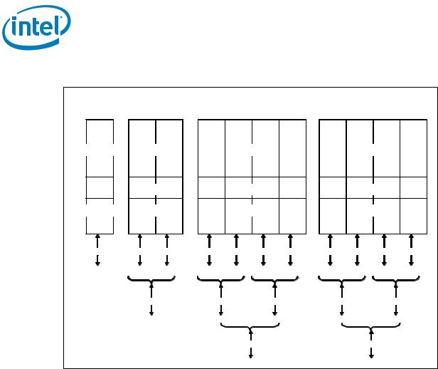
•Negotiating down to narrower widths is supported, see Figure 1-3:
16 |
Intel® Xeon® Processor E5-1600/E5-2600/E5-4600 Product Families |
|
Datasheet Volume One |

Overview
—x16 port (Port 2 & Port 3) may negotiate down to x8, x4, x2, or x1.
—x8 port (Port 1) may negotiate down to x4, x2, or x1.
—x4 port (Port 0) may negotiate down to x2, or x1.
—When negotiating down to narrower widths, there are caveats as to how lane reversal is supported.
•Non-Transparent Bridge (NTB) is supported by PCIe* Port3a/IOU1. For more details on NTB mode operation refer to PCI Express Base Specification - Revision 3.0:
—x4 or x8 widths and at PCIe* 1.0, 2.0, 3.0 speeds
—Two usage models; NTB attached to a Root Port or NTB attached to another NTB
—Supports three 64-bit BARs
—Supports posted writes and non-posted memory read transactions across the NTB
—Supports INTx, MSI and MSI-X mechanisms for interrupts on both side of NTB in upstream direction only
•Address Translation Services (ATS) 1.0 support
•Hierarchical PCI-compliant configuration mechanism for downstream devices.
•Traditional PCI style traffic (asynchronous snooped, PCI ordering).
•PCI Express* extended configuration space. The first 256 bytes of configuration space aliases directly to the PCI compatibility configuration space. The remaining portion of the fixed 4-KB block of memory-mapped space above that (starting at 100h) is known as extended configuration space.
•PCI Express* Enhanced Access Mechanism. Accessing the device configuration space in a flat memory mapped fashion.
•Automatic discovery, negotiation, and training of link out of reset.
•Supports receiving and decoding 64 bits of address from PCI Express*.
—Memory transactions received from PCI Express* that go above the top of physical address space (when Intel VT-d is enabled, the check would be against the translated HPA (Host Physical Address) address) are reported as errors by the processor.
—Outbound access to PCI Express* will always have address bits 63 to 46 cleared.
•Re-issues Configuration cycles that have been previously completed with the Configuration Retry status.
•Power Management Event (PME) functions.
•Message Signaled Interrupt (MSI and MSI-X) messages
•Degraded Mode support and Lane Reversal support
•Static lane numbering reversal and polarity inversion support
Intel® Xeon® Processor E5-1600/E5-2600/E5-4600 Product Families |
17 |
Datasheet Volume One |
|
Overview
Figure 1-3. PCI Express* Lane Partitioning and Direct Media Interface Gen 2 (DMI2)
Port 0 |
Port 1 |
|
Port 2 |
|
|
Port 3 |
|
|||
(IOU2) |
|
(IOU0) |
|
|
(IOU1) |
|
||||
DMI / PCIe |
|
|
|
|
||||||
PCIe |
|
PCIe |
|
|
PCIe |
|
||||
|
|
|
|
|
||||||
Transaction |
Transaction |
|
Transaction |
|
|
Transaction |
|
|||
Link |
Link |
|
Link |
|
|
Link |
|
|||
Physical |
Physical |
|
Physical |
|
|
Physical |
|
|||
0…3 |
0…3 |
4…7 |
|
4…7 |
8…11 |
12..15 |
|
4…7 |
8…11 |
12..15 |
X4 |
X4 |
X4 |
X4 |
X4 |
X4 |
X4 |
X4 |
X4 |
X4 |
X4 |
DMI |
Port 1a |
Port 1b |
Port 2a |
Port 2b |
Port 2c |
Port 2d |
Port 3a |
Port 3b |
Port 3c |
Port 3d |
|
X8 |
|
X8 |
|
X8 |
|
X8 |
|
X8 |
|
|
Port 1a |
Port 2a |
Port 2c |
Port 3a |
Port 3c |
|||||
|
|
|
|
X16 |
|
|
X16 |
|
||
|
|
|
|
Port 2a |
|
|
Port 3a |
|
||
1.2.3Direct Media Interface Gen 2 (DMI2)
•Serves as the chip-to-chip interface to the Intel® C600 Chipset
•The DMI2 port supports x4 link width and only operates in a x4 mode when in DMI2
•Operates at PCI Express* 1.0 or 2.0 speeds
•Transparent to software
•Processor and peer-to-peer writes and reads with 64-bit address support
•APIC and Message Signaled Interrupt (MSI) support. Will send Intel-defined “End of Interrupt” broadcast message when initiated by the processor.
•System Management Interrupt (SMI), SCI, and SERR error indication
•Static lane numbering reversal support
•Supports DMI2 virtual channels VC0, VC1, VCm, and VCp
1.2.4Intel® QuickPath Interconnect (Intel® QPI)
•Compliant with Intel QuickPath Interconnect v1.1 standard packet formats
•Implements two full width Intel QPI ports
•Full width port includes 20 data lanes and 1 clock lane
•64 byte cache-lines
•Isochronous access support for Quality of Service (QoS), native 1 and 2 socket platforms - Intel® Xeon® processor E5-1600 and E5-2600 product families only
18 |
Intel® Xeon® Processor E5-1600/E5-2600/E5-4600 Product Families |
|
Datasheet Volume One |

Overview
•Home snoop based coherency
•3-bit Node ID
•46-bit physical addressing support
•No Intel QuickPath Interconnect bifurcation support
•Differential signaling
•Forwarded clocking
•Up to 8.0 GT/s data rate (up to 16 GB/s direction peak bandwidth per port)
—All ports run at same operational frequency
—Reference Clock is 100 MHz
—Slow boot speed initialization at 50 MT/s
•Common reference clocking (same clock generator for both sender and receiver)
•Intel® Interconnect Built-In-Self-Test (Intel® IBIST) for high-speed testability
•Polarity and Lane reversal (Rx side only)
1.2.5Platform Environment Control Interface (PECI)
The PECI is a one-wire interface that provides a communication channel between a PECI client (the processor) and a PECI master (the PCH).
•Supports operation at up to 2 Mbps data transfers
•Link layer improvements to support additional services and higher efficiency over PECI 2.0 generation
•Services include CPU thermal and estimated power information, control functions for power limiting, P-state and T-state control, and access for Machine Check Architecture registers and PCI configuration space (both within the processor package and downstream devices)
•PECI address determined by SOCKET_ID configuration
•Single domain (Domain 0) is supported
1.3Power Management Support
1.3.1Processor Package and Core States
•ACPI C-states as implemented by the following processor C-states:
—Package: PC0, PC1/PC1E, PC2, PC3, PC6 (Package C7 is not supported)
—Core: CC0, CC1, CC1E, CC3, CC6, CC7
•Enhanced Intel SpeedStep® Technology
1.3.2System States Support
•S0, S1, S3, S4, S5
1.3.3Memory Controller
•Multiple CKE power down modes
•Multiple self-refresh modes
Intel® Xeon® Processor E5-1600/E5-2600/E5-4600 Product Families |
19 |
Datasheet Volume One |
|

Overview
•Memory thermal monitoring via MEM_HOT_C01_N and MEM_HOT_C23_N Signals
1.3.4PCI Express
•L0s is not supported
•L1 ASPM power management capability
1.3.5Intel QuickPath Interconnect
•L0s is not supported
•L0p and L1 power management capabilities
1.4Thermal Management Support
•Digital Thermal Sensor with multiple on-die temperature zones
•Adaptive Thermal Monitor
•THERMTRIP_N and PROCHOT_N signal support
•On-Demand mode clock modulation
•Open and Closed Loop Thermal Throttling (OLTT/CLTT) support for system memory in addition to Hybrid OLTT/CLTT mode
•Fan speed control with DTS
•Two integrated SMBus masters for accessing thermal data from DIMMs
•New Memory Thermal Throttling features via MEM_HOT_C{01/23}_N signals
•Running Average Power Limit (RAPL), Processor and DRAM Thermal and Power Optimization Capabilities
1.5Package Summary
The processor socket is a 52.5 x 45 mm FCLGA package (LGA2011-0 land FCLGA10).
1.6Terminology
Term |
Description |
|
|
ASPM |
Active State Power Management |
|
|
BMC |
Baseboard Management Controllers |
|
|
Cbo |
Cache and Core Box. It is a term used for internal logic providing ring interface to |
|
LLC and Core. |
|
|
DDR3 |
Third generation Double Data Rate SDRAM memory technology that is the |
|
successor to DDR2 SDRAM |
|
|
DMA |
Direct Memory Access |
|
|
DMI |
Direct Media Interface |
|
|
DMI2 |
Direct Media Interface Gen 2 |
|
|
DTS |
Digital Thermal Sensor |
|
|
ECC |
Error Correction Code |
|
|
20 |
Intel® Xeon® Processor E5-1600/E5-2600/E5-4600 Product Families |
|
Datasheet Volume One |
Overview
|
Term |
Description |
|
|
|
|
|
|
Enhanced Intel |
Allows the operating system to reduce power consumption when performance is |
|
|
SpeedStep® Technology |
not needed. |
|
|
|
|
|
|
Execute Disable Bit |
The Execute Disable bit allows memory to be marked as executable or non- |
|
|
|
executable, when combined with a supporting operating system. If code |
|
|
|
attempts to run in non-executable memory the processor raises an error to the |
|
|
|
operating system. This feature can prevent some classes of viruses or worms |
|
|
|
that exploit buffer overrun vulnerabilities and can thus help improve the overall |
|
|
|
security of the system. See the Intel® 64 and IA-32 Architectures Software |
|
|
|
Developer's Manuals for more detailed information. |
|
|
|
|
|
|
Flit |
Flow Control Unit. The Intel QPI Link layer’s unit of transfer; 1 Flit = 80-bits. |
|
|
|
|
|
|
Functional Operation |
Refers to the normal operating conditions in which all processor specifications, |
|
|
|
including DC, AC, system bus, signal quality, mechanical, and thermal, are |
|
|
|
satisfied. |
|
|
|
|
|
|
IMC |
The Integrated Memory Controller. A Memory Controller that is integrated in the |
|
|
|
processor die. |
|
|
|
|
|
|
IIO |
The Integrated I/O Controller. An I/O controller that is integrated in the |
|
|
|
processor die. |
|
|
|
|
|
|
Intel® ME |
Intel® Management Engine (Intel® ME) |
|
|
|
|
|
|
Intel® QuickData |
Intel QuickData Technology is a platform solution designed to maximize the |
|
|
Technology |
throughput of server data traffic across a broader range of configurations and |
|
|
|
server environments to achieve faster, scalable, and more reliable I/O. |
|
|
|
|
|
|
Intel® QuickPath |
A cache-coherent, link-based Interconnect specification for Intel processors, |
|
|
Interconnect (Intel® QPI) |
chipsets, and I/O bridge components. |
|
|
|
|
|
|
Intel® 64 Technology |
64-bit memory extensions to the IA-32 architecture. Further details on Intel 64 |
|
|
|
architecture and programming model can be found at |
|
|
|
http://developer.intel.com/technology/intel64/. |
|
|
|
|
|
|
Intel® Turbo Boost |
Intel® Turbo Boost Technology is a way to automatically run the processor core |
|
|
Technology |
faster than the marked frequency if the part is operating under power, |
|
|
|
temperature, and current specifications limits of the Thermal Design Power |
|
|
|
(TDP). This results in increased performance of both single and multi-threaded |
|
|
|
applications. |
|
|
|
|
|
|
Intel® TXT |
Intel® Trusted Execution Technology |
|
|
|
|
|
|
Intel® Virtualization |
Processor virtualization which when used in conjunction with Virtual Machine |
|
|
Technology (Intel® VT) |
Monitor software enables multiple, robust independent software environments |
|
|
|
inside a single platform. |
|
|
|
|
|
|
Intel® VT-d |
Intel® Virtualization Technology (Intel® VT) for Directed I/O. Intel VT-d is a |
|
|
|
hardware assist, under system software (Virtual Machine Manager or OS) |
|
|
|
control, for enabling I/O device virtualization. Intel VT-d also brings robust |
|
|
|
security by providing protection from errant DMAs by using DMA remapping, a |
|
|
|
key feature of Intel VT-d. |
|
|
|
|
|
|
Intel® Xeon® processor |
Intel’s 32-nm processor design, follow-on to the 32-nm 2nd Generation Intel® |
|
|
E5-1600 product family |
Core™ Processor Family design. It is the first processor for use in Intel® Xeon® |
|
|
and Intel® Xeon® |
processor E5-1600 and E5-2600 product families-based platforms. Intel® |
|
|
processor E5-2600 |
Xeon® processor E5-1600 product family and Intel® Xeon® processor E5-2600 |
|
|
product family |
product family supports Efficient Performance server, workstation and HPC |
|
|
|
platforms |
|
|
|
|
|
|
Intel® Xeon® processor |
Intel’s 32-nm processor design, follow-on to the 32-nm processor design. It is |
|
|
E5-4600 product family |
the first processor for use in Intel® Xeon® processor E5-4600 product family- |
|
|
|
based platforms. Intel® Xeon® processor E5-4600 product family supports |
|
|
|
scalable server and HPC platforms for two or more processors, including glueless |
|
|
|
four-way platforms. |
|
|
|
|
|
|
Integrated Heat Spreader |
A component of the processor package used to enhance the thermal |
|
|
(IHS) |
performance of the package. Component thermal solutions interface with the |
|
|
|
processor at the IHS surface. |
|
|
|
|
|
|
Jitter |
Any timing variation of a transition edge or edges from the defined Unit Interval |
|
|
|
(UI). |
|
|
|
|
|
|
IOV |
I/O Virtualization |
|
|
|
|
|
|
LGA2011-0 land FCLGA10 |
The processor mates with the system board through this surface mount, |
|
|
Socket |
LGA2011-0 land FCLGA10 contact socket, for the Intel® Xeon® processor E5 |
|
|
|
product family-based platform. |
|
|
|
|
|
Intel® Xeon® Processor E5-1600/E5-2600/E5-4600 Product Families |
21 |
||
Datasheet Volume One |
|
|
|

|
|
|
|
Overview |
|
|
|
|
|
|
|
|
Term |
Description |
|
|
|
|
|
|
|
|
LLC |
Last Level Cache |
|
|
|
|
|
|
|
|
LRDIMM |
Load Reduced Dual In-line Memory Module |
|
|
|
|
|
|
|
|
NCTF |
Non-Critical to Function: NCTF locations are typically redundant ground or non- |
|
|
|
|
critical reserved, so the loss of the solder joint continuity at end of life conditions |
|
|
|
|
will not affect the overall product functionality. |
|
|
|
|
|
|
|
|
NEBS |
Network Equipment Building System. NEBS is the most common set of |
|
|
|
|
environmental design guidelines applied to telecommunications equipment in the |
|
|
|
|
United States. |
|
|
|
|
|
|
|
|
PCH |
Platform Controller Hub (Intel® C600 Chipset). The next generation chipset with |
|
|
|
|
centralized platform capabilities including the main I/O interfaces along with |
|
|
|
|
display connectivity, audio features, power management, manageability, security |
|
|
|
|
and storage features. |
|
|
|
|
|
|
|
|
PCU |
Power Control Unit |
|
|
|
|
|
|
|
|
PCI Express* 3.0 |
The third generation PCI Express* specification that operates at twice the speed |
|
|
|
|
of PCI Express* 2.0 (8 Gb/s); however, PCI Express* 3.0 is completely backward |
|
|
|
|
compatible with PCI Express* 1.0 and 2.0. |
|
|
|
|
|
|
|
|
PCI Express* 3 |
PCI Express* Generation 3.0 |
|
|
|
|
|
|
|
|
PCI Express* 2 |
PCI Express* Generation 2.0 |
|
|
|
|
|
|
|
|
PCI Express* |
PCI Express* Generation 2.0/3.0 |
|
|
|
|
|
|
|
|
PECI |
Platform Environment Control Interface |
|
|
|
|
|
|
|
|
Phit |
Physical Unit. An Intel® QPI terminology defining units of transfer at the physical |
|
|
|
|
layer. 1 Phit is equal to 20 bits in ‘full width mode’ and 10 bits in ‘half width |
|
|
|
|
mode’ |
|
|
|
|
|
|
|
|
Processor |
The 64-bit, single-core or multi-core component (package) |
|
|
|
|
|
|
|
|
Processor Core |
The term “processor core” refers to silicon die itself which can contain multiple |
|
|
|
|
execution cores. Each execution core has an instruction cache, data cache, and |
|
|
|
|
256-KB L2 cache. All execution cores share the L3 cache. All DC and signal |
|
|
|
|
integrity specifications are measured at the processor die (pads), unless |
|
|
|
|
otherwise noted. |
|
|
|
|
|
|
|
|
RDIMM |
Registered Dual In-line Memory Module |
|
|
|
|
|
|
|
|
Rank |
A unit of DRAM corresponding four to eight devices in parallel, ignoring ECC. |
|
|
|
|
These devices are usually, but not always, mounted on a single side of a DDR3 |
|
|
|
|
DIMM. |
|
|
|
|
|
|
|
|
Scalable-2S |
Intel® Xeon® processor E5 product family-based platform targeted for scalable |
|
|
|
|
designs using third party Node Controller chip. In these designs, Node Controller |
|
|
|
|
is used to scale the design beyond one/two/four sockets. |
|
|
|
|
|
|
|
|
SCI |
System Control Interrupt. Used in ACPI protocol. |
|
|
|
|
|
|
|
|
SSE |
Intel® Streaming SIMD Extensions (Intel® SSE) |
|
|
|
|
|
|
|
|
SKU |
A processor Stock Keeping Unit (SKU) to be installed in either server or |
|
|
|
|
workstation platforms. Electrical, power and thermal specifications for these |
|
|
|
|
SKU’s are based on specific use condition assumptions. Server processors may |
|
|
|
|
be further categorized as Efficient Performance server, workstation and HPC |
|
|
|
|
SKUs. For further details on use condition assumptions, please refer to the latest |
|
|
|
|
Product Release Qualification (PRQ) Report available via your Customer Quality |
|
|
|
|
Engineer (CQE) contact. |
|
|
|
|
|
|
|
|
SMBus |
System Management Bus. A two-wire interface through which simple system and |
|
|
|
|
power management related devices can communicate with the rest of the |
|
|
|
|
system. It is based on the principals of the operation of the I2C* two-wire serial |
|
|
|
|
bus from Philips Semiconductor. |
|
|
|
|
|
|
|
|
Storage Conditions |
A non-operational state. The processor may be installed in a platform, in a tray, |
|
|
|
|
or loose. Processors may be sealed in packaging or exposed to free air. Under |
|
|
|
|
these conditions, processor landings should not be connected to any supply |
|
|
|
|
voltages, have any I/Os biased or receive any clocks. Upon exposure to “free air” |
|
|
|
|
(i.e., unsealed packaging or a device removed from packaging material) the |
|
|
|
|
processor must be handled in accordance with moisture sensitivity labeling |
|
|
|
|
(MSL) as indicated on the packaging material. |
|
|
|
|
|
|
|
|
TAC |
Thermal Averaging Constant |
|
|
|
|
|
22 |
|
|
|
Intel® Xeon® Processor E5-1600/E5-2600/E5-4600 Product Families |
|
|
|
|
Datasheet Volume One |

Overview
Term |
Description |
|
|
TDP |
Thermal Design Power |
|
|
TSOD |
Thermal Sensor on DIMM |
|
|
UDIMM |
Unbuffered Dual In-line Module |
|
|
Uncore |
The portion of the processor comprising the shared cache, IMC, HA, PCU, UBox, |
|
and Intel QPI link interface. |
|
|
Unit Interval |
Signaling convention that is binary and unidirectional. In this binary signaling, |
|
one bit is sent for every edge of the forwarded clock, whether it be a rising edge |
|
or a falling edge. If a number of edges are collected at instances t1, t2, tn,...., tk |
|
then the UI at instance “n” is defined as: |
|
UI n = t n - t n - 1 |
VCC |
Processor core power supply |
VSS |
Processor ground |
VCCD_01, VCCD_23 |
Variable power supply for the processor system memory interface. VCCD is the |
|
generic term for VCCD_01, VCCD_23. |
x1 |
Refers to a Link or Port with one Physical Lane |
|
|
x4 |
Refers to a Link or Port with four Physical Lanes |
|
|
x8 |
Refers to a Link or Port with eight Physical Lanes |
|
|
x16 |
Refers to a Link or Port with sixteen Physical Lanes |
|
|
1.7Related Documents
|
Refer to the following documents for additional information. |
|
Table 1-1. |
Referenced Documents (Sheet 1 of 2) |
|
|
|
|
|
Document |
Location |
|
|
|
|
Intel® Xeon® Processor E5 Product Family Datasheet Volume Two |
http://www.intel.com |
|
|
|
|
Intel® Xeon® Processor E5-1600/E5-2600/E5-4600 Product Families |
http://www.intel.com |
|
Thermal/Mechanical Design Guide |
|
|
|
|
|
Intel® Xeon® Processor E5-1600/E5-2600/E5-4600 Product Families |
http://www.intel.com |
|
– BSDL (Boundary Scan Description Language) |
|
|
|
|
|
Intel® C600 Series Chipset Data Sheet |
http://www.intel.com |
|
|
|
|
Intel® 64 and IA-32 Architectures Software Developer’s Manual |
http://www.intel.com |
|
(SDM) Volumes 1, 2, and 3 |
|
|
|
|
|
Advanced Configuration and Power Interface Specification 3.0 |
http://www.acpi.info |
|
|
|
|
PCI Local Bus Specification 3.0 |
http://www.pcisig.com/specifications |
|
|
|
|
PCI Express Base Specification - Revision 2.1 and 1.1 |
http://www.pcisig.com |
|
PCI Express Base Specification - Revision 3.0 |
|
|
|
|
|
System Management Bus (SMBus) Specification |
http://smbus.org/ |
|
|
|
|
DDR3 SDRAM Specification |
http://www.jedec.org |
|
|
|
|
Low (JESD22-A119) and High (JESD-A103) Temperature Storage Life |
http://www.jedec.org |
|
Specifications |
|
|
|
|
|
Intel 64 and IA-32 Architectures Software Developer's Manuals |
http://www.intel.com/products/proce |
|
• Volume 1: Basic Architecture |
|
|
• Volume 2A: Instruction Set Reference, A-M |
ssor/manuals/index.htm |
|
|
|
|
• Volume 2B: Instruction Set Reference, N-Z |
|
|
• Volume 3A: System Programming Guide |
|
|
• Volume 3B: System Programming Guide |
|
|
Intel® 64 and IA-32 Architectures Optimization Reference Manual |
|
|
|
|
Intel® Xeon® Processor E5-1600/E5-2600/E5-4600 Product Families |
23 |
Datasheet Volume One |
|

|
|
|
|
Overview |
Table 1-1. Referenced Documents (Sheet 2 of 2) |
|
|||
|
|
|
|
|
|
|
|
Document |
Location |
|
|
|
|
|
|
|
|
Intel® Virtualization Technology Specification for Directed I/O |
http://download.intel.com/technolog |
|
|
|
Architecture Specification |
y/computing/vptech/Intel(r)_VT_for_ |
|
|
|
|
Direct_IO.pdf |
|
|
|
|
|
|
|
|
Intel® Trusted Execution Technology Software Development Guide |
http://www.intel.com/technology/sec |
|
|
|
|
urity/ |
|
|
|
|
|
1.8State of Data
The data contained within this document is the most accurate information available by the publication date of this document.
§
24 |
Intel® Xeon® Processor E5-1600/E5-2600/E5-4600 Product Families |
|
Datasheet Volume One |

Interfaces
2 Interfaces
This chapter describes the interfaces supported by the processor.
2.1System Memory Interface
2.1.1System Memory Technology Support
The Integrated Memory Controller (IMC) supports DDR3 protocols with four independent 64-bit memory channels with 8 bits of ECC for each channel (total of 72-bits) and supports 1 to 3 DIMMs per channel depending on the type of memory installed. The type of memory supported by the processor is dependent on the target platform:
•Intel® Xeon® processor E5 product family-based platforms support:
—ECC registered DIMMs: with a maximum of three DIMMs per channel allowing up to eight device ranks per channel.
—ECC and non-ECC unbuffered DIMMs: with a maximum of two DIMMs per channel thus allowing up to four device ranks per channel. Support for mixed non-ECC with ECC un-buffered DIMM configurations.
2.1.2System Memory Timing Support
The IMC supports the following DDR3 Speed Bin, CAS Write Latency (CWL), and command signal mode timings on the main memory interface:
•tCL = CAS Latency
•tRCD = Activate Command to READ or WRITE Command delay
•tRP = PRECHARGE Command Period
•CWL = CAS Write Latency
•Command Signal modes = 1n indicates a new command may be issued every clock and 2n indicates a new command may be issued every 2 clocks. Command launch mode programming depends on the transfer rate and memory configuration.
Intel® Xeon® Processor E5-1600/E5-2600/E5-4600 Product Families |
25 |
Datasheet Volume One |
|
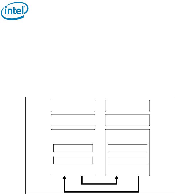
Interfaces
2.2PCI Express* Interface
This section describes the PCI Express* 3.0 interface capabilities of the processor. See the PCI Express* Base Specification for details of PCI Express* 3.0.
2.2.1PCI Express* Architecture
Compatibility with the PCI addressing model is maintained to ensure that all existing applications and drivers operate unchanged. The PCI Express* configuration uses standard mechanisms as defined in the PCI Plug-and-Play specification.
The PCI Express* architecture is specified in three layers: Transaction Layer, Data Link Layer, and Physical Layer. The partitioning in the component is not necessarily along these same boundaries. Refer to Figure 2-1 for the PCI Express* Layering Diagram.
Figure 2-1. PCI Express* Layering Diagram
Transaction
Data Link
Physical
Logical Sub-Block
Electrical Sub-Block
RX TX
Transaction
Data Link
Physical
Logical Sub-Block
Electrical Sub-Block
RX TX
PCI Express* uses packets to communicate information between components. Packets are formed in the Transaction and Data Link Layers to carry the information from the transmitting component to the receiving component. As the transmitted packets flow through the other layers, they are extended with additional information necessary to handle packets at those layers. At the receiving side, the reverse process occurs and packets get transformed from their Physical Layer representation to the Data Link Layer representation and finally (for Transaction Layer Packets) to the form that can be processed by the Transaction Layer of the receiving device.
26 |
Intel® Xeon® Processor E5-1600/E5-2600/E5-4600 Product Families |
|
Datasheet Volume One |
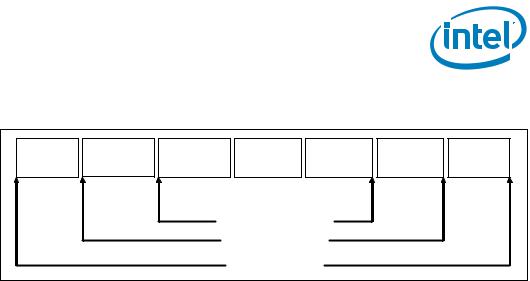
Interfaces
Figure 2-2. Packet Flow through the Layers
Framing |
Sequence |
Header |
Data |
ECRC |
LCRC |
Framing |
|
Number |
|||||||
|
|
|
|
|
|
||
|
|
|
Transaction Layer |
|
|
||
|
|
|
Data Link Layer |
|
|
||
|
|
|
Physical Layer |
|
|
|
|
2.2.1.1Transaction Layer
The upper layer of the PCI Express* architecture is the Transaction Layer. The Transaction Layer's primary responsibility is the assembly and disassembly of Transaction Layer Packets (TLPs). TLPs are used to communicate transactions, such as read and write, as well as certain types of events. The Transaction Layer also manages flow control of TLPs.
2.2.1.2Data Link Layer
The middle layer in the PCI Express* stack, the Data Link Layer, serves as an intermediate stage between the Transaction Layer and the Physical Layer. Responsibilities of Data Link Layer include link management, error detection, and error correction.
The transmission side of the Data Link Layer accepts TLPs assembled by the Transaction Layer, calculates and applies data protection code and TLP sequence number, and submits them to Physical Layer for transmission across the Link. The receiving Data Link Layer is responsible for checking the integrity of received TLPs and for submitting them to the Transaction Layer for further processing. On detection of TLP error(s), this layer is responsible for requesting retransmission of TLPs until information is correctly received, or the Link is determined to have failed. The Data Link Layer also generates and consumes packets which are used for Link management functions.
2.2.1.3Physical Layer
The Physical Layer includes all circuitry for interface operation, including driver and input buffers, parallel-to-serial and serial-to-parallel conversion, PLL(s), and impedance matching circuitry. It also includes logical functions related to interface initialization and maintenance. The Physical Layer exchanges data with the Data Link Layer in an implementation-specific format, and is responsible for converting this to an appropriate serialized format and transmitting it across the PCI Express* Link at a frequency and width compatible with the remote device.
2.2.2PCI Express* Configuration Mechanism
The PCI Express* link is mapped through a PCI-to-PCI bridge structure.
PCI Express* extends the configuration space to 4096 bytes per-device/function, as compared to 256 bytes allowed by the Conventional PCI Specification. PCI Express* configuration space is divided into a PCI-compatible region (which consists of the first
Intel® Xeon® Processor E5-1600/E5-2600/E5-4600 Product Families |
27 |
Datasheet Volume One |
|

Interfaces
256 bytes of a logical device's configuration space) and an extended PCI Express* region (which consists of the remaining configuration space). The PCI-compatible region can be accessed using either the mechanisms defined in the PCI specification or using the enhanced PCI Express* configuration access mechanism described in the PCI Express* Enhanced Configuration Mechanism section.
The PCI Express* Host Bridge is required to translate the memory-mapped PCI Express* configuration space accesses from the host processor to PCI Express* configuration cycles. To maintain compatibility with PCI configuration addressing mechanisms, it is recommended that system software access the enhanced configuration space using 32-bit operations (32-bit aligned) only.
See the PCI Express* Base Specification for details of both the PCI-compatible and PCI Express* Enhanced configuration mechanisms and transaction rules.
2.3DMI2/PCI Express* Interface
Direct Media Interface 2 (DMI2) connects the processor to the Platform Controller Hub (PCH). DMI2 is similar to a four-lane PCI Express* supporting a speed of 5 GT/s per lane. This interface can be configured at power-on to serve as a x4 PCI Express* link based on the setting of the SOCKET_ID[1:0] and FRMAGENT signal for processors not connected to a PCH.
Note: Only DMI2 x4 configuration is supported.
2.3.1DMI2 Error Flow
DMI2 can only generate SERR in response to errors, never SCI, SMI, MSI, PCI INT, or GPE. Any DMI2 related SERR activity is associated with Device 0.
2.3.2Processor/PCH Compatibility Assumptions
The processor is compatible with the PCH and is not compatible with any previous MCH or ICH products.
2.3.3DMI2 Link Down
The DMI2 link going down is a fatal, unrecoverable error. If the DMI2 data link goes to data link down, after the link was up, then the DMI2 link hangs the system by not allowing the link to retrain to prevent data corruption. This is controlled by the PCH.
Downstream transactions that had been successfully transmitted across the link prior to the link going down may be processed as normal. No completions from downstream, non-posted transactions are returned upstream over the DMI2 link after a link down event.
2.4Intel QuickPath Interconnect
The Intel QuickPath Interconnect is a high speed, packetized, point-to-point interconnect used in the 2nd Generation Intel(r) Core(TM) Processor Family. The narrow high-speed links stitch together processors in distributed shared memory and integrated I/O platform architecture. It offers much higher bandwidth with low latency. The Intel QuickPath Interconnect has an efficient architecture allowing more interconnect performance to be achieved in real systems. It has a snoop protocol
28 |
Intel® Xeon® Processor E5-1600/E5-2600/E5-4600 Product Families |
|
Datasheet Volume One |

Interfaces
optimized for low latency and high scalability, as well as packet and lane structures enabling quick completions of transactions. Reliability, availability, and serviceability features (RAS) are built into the architecture.
The physical connectivity of each interconnect link is made up of twenty differential signal pairs plus a differential forwarded clock. Each port supports a link pair consisting of two uni-directional links to complete the connection between two components. This supports traffic in both directions simultaneously. To facilitate flexibility and longevity, the interconnect is defined as having five layers: Physical, Link, Routing, Transport, and Protocol.
•The Physical layer consists of the actual wires carrying the signals, as well as circuitry and logic to support ancillary features required in the transmission and receipt of the 1s and 0s. The unit of transfer at the Physical layer is 20-bits, which is called a Phit (for Physical unit).
•The Link layer is responsible for reliable transmission and flow control. The Link layer’s unit of transfer is 80-bits, which is called a Flit (for Flow control unit).
•The Routing layer provides the framework for directing packets through the fabric.
•The Transport layer is an architecturally defined layer (not implemented in the initial products) providing advanced routing capability for reliable end-to-end transmission.
•The Protocol layer is the high-level set of rules for exchanging packets of data between devices. A packet is comprised of an integral number of Flits.
The Intel QuickPath Interconnect includes a cache coherency protocol to keep the distributed memory and caching structures coherent during system operation. It supports both low-latency source snooping and a scalable home snoop behavior. The coherency protocol provides for direct cache-to-cache transfers for optimal latency.
Intel® Xeon® Processor E5-1600/E5-2600/E5-4600 Product Families |
29 |
Datasheet Volume One |
|

2.5Platform Environment Control Interface (PECI)
The Platform Environment Control Interface (PECI) uses a single wire for self-clocking and data transfer. The bus requires no additional control lines. The physical layer is a self-clocked one-wire bus that begins each bit with a driven, rising edge from an idle level near zero volts. The duration of the signal driven high depends on whether the bit value is a logic ‘0’ or logic ‘1’. PECI also includes variable data transfer rate established with every message. In this way, it is highly flexible even though underlying logic is simple.
The interface design was optimized for interfacing to Intel processor and chipset components in both single processor and multiple processor environments. The single wire interface provides low board routing overhead for the multiple load connections in the congested routing area near the processor and chipset components. Bus speed, error checking, and low protocol overhead provides adequate link bandwidth and reliability to transfer critical device operating conditions and configuration information.
The PECI bus offers:
•A wide speed range from 2 Kbps to 2 Mbps
•CRC check byte used to efficiently and atomically confirm accurate data delivery
•Synchronization at the beginning of every message minimizes device timing accuracy requirements
Note: The PECI commands described in this document apply primarily to the Intel® Xeon® processor E5-1600/E5-2600/E5-4600 product families. The processors utilizes the capabilities described in this document to indicate support for four memory channels. Refer to Table 2-1 for the list of PECI commands supported by the processors.
Table 2-1. Summary of Processor-specific PECI Commands
Command |
Supported on the Processor |
|
|
Ping() |
Yes |
|
|
GetDIB() |
Yes |
|
|
GetTemp() |
Yes |
|
|
RdPkgConfig() |
Yes |
|
|
WrPkgConfig() |
Yes |
|
|
RdIAMSR() |
Yes |
|
|
WrIAMSR() |
No |
|
|
RdPCIConfig() |
Yes |
|
|
WrPCIConfig() |
No |
|
|
RdPCIConfigLocal() |
Yes |
|
|
WrPCIConfigLocal() |
Yes |
|
|
2.5.1PECI Client Capabilities
The processor PECI client is designed to support the following sideband functions:
•Processor and DRAM thermal management
•Platform manageability functions including thermal, power, and error monitoring
—The platform ‘power’ management includes monitoring and control for both the processor and DRAM subsystem to assist with data center power limiting.
•Processor interface tuning and diagnostics capabilities (Intel® Interconnect BIST).
30 |
Intel® Xeon® Processor E5-1600/E5-2600/E5-4600 Product Families |
|
Datasheet Volume One |
Loading...