

Page 1

Intel® NUC 9 Extreme/Pro Kit
Technical Product Specification
Revision 1.0
Regulatory Model: NUC9QN
December 2019
Intel® NUC 9 Extreme Kit NUC9i9QNX, NUC9i7QNX, NUC9i5QNX, Intel® NUC 9 Pro Kit NUC9VXQNX, or NUC9V7QNX may contain design defects or
errors known as errata that may cause the product to deviate from published specifications. Current characterized errata, if any, are documented in
this product specification
Page 2

Revision History
Revision
Revision History
Date
1.0
First release
December 2019
Disclaimer
This product specification applies only to the standard Intel® NUC 9 Extreme/Pro Kits with BIOS identifier
QXCFL579 or QNCFLX70.
INFORMATION IN THIS DOCUMENT IS PROVIDED IN CONNECTION WITH INTEL® PRODUCTS. NO LICENSE, EXPRESS OR
IMPLIED, BY ESTOPPEL OR OTHERWISE, TO ANY INTELLECTUAL PROPERTY RIGHTS IS GRANTED BY THIS DOCUMENT.
EXCEPT AS PROVIDED IN INTEL’S TERMS AND CONDITIONS OF SALE FOR SUCH PRODUCTS, INTEL ASSUMES NO
LIABILITY WHATSOEVER, AND INTEL DISCLAIMS ANY EXPRESS OR IMPLIED WARRANTY, RELATING TO SALE AND/OR
USE OF INTEL PRODUCTS INCLUDING LIABILITY OR WARRANTIES RELATING TO FITNESS FOR A PARTICULAR PURPOSE,
MERCHANTABILITY, OR INFRINGEMENT OF ANY PATENT, COPYRIGHT OR OTHER INTELLECTUAL PROPERTY RIGHT.
UNLESS OTHERWISE AGREED IN WRITING BY INTEL, THE INTEL PRODUCTS ARE NOT DESIGNED NOR INTENDED FOR
ANY APPLICATION IN WHICH THE FAILURE OF THE INTEL PRODUCT COULD CREATE A SITUATION WHERE PERSONAL
INJURY OR DEATH MAY OCCUR.
All Intel® NUC 9 Extreme/Pro Kits are evaluated as Information Technology Equipment (I.T.E.) for use in personal
computers (PC) for installation in homes, offices, schools, computer rooms, and similar locations. The suitability of this
product for other PC or embedded non-PC applications or other environments, such as medical, industrial, alarm systems,
test equipment, etc. may not be supported without further evaluation by Intel.
Intel Corporation may have patents or pending patent applications, trademarks, copyrights, or other intellectual property
rights that relate to the presented subject matter. The furnishing of documents and other materials and information does
not provide any license, express or implied, by estoppel or otherwise, to any such patents, trademarks, copyrights, or
other intellectual property rights.
Intel may make changes to specifications and product descriptions at any time, without notice.
Designers must not rely on the absence or characteristics of any features or instructions marked “reserved” or
“undefined.” Intel reserves these for future definition and shall have no responsibility whatsoever for conflicts or
incompatibilities arising from future changes to them.
Intel processor numbers are not a measure of performance. Processor numbers differentiate features within each
processor family, not across different processor families: Go to:
Learn About Intel® Processor Numbers
Intel® NUC 9 Extreme/Pro Kits may contain design defects or errors known as errata, which may cause the product to
deviate from published specifications. Current characterized errata are available on request.
Contact your local Intel sales office or your distributor to obtain the latest specifications before placing your product
order.
Intel, the Intel logo and Intel Core are trademarks of Intel Corporation in the U.S. and/or other countries.
* Other names and brands may be claimed as the property of others.
Copyright © 2019 Intel Corporation. All rights reserved.
Page 3

iii
Preface
This Product Specification specifies the layout, components, connectors, power and
environmental features for the Intel® NUC 9 Extreme Kit NUC9i9QNX, NUC9i7QNX, NUC9i5QNX,
Intel® NUC 9 Pro Kit NUC9VXQNX, and NUC9V7QNX.
NOTE
In this document, the use of “Intel® NUC 9 Extreme Kit” will refer to the NUC9i9QNX, NUC9i7QNX,
or NUC9i5QNX versions. The use of “Intel® NUC 9 Pro Kit” will refer to the NUC9VXQNX or
NUC9V7QNX versions. When possible further consolidation of the naming convention will be
used “NUC 9 Extreme/Pro Kit” when referring to shared features or capabilities. The usage of
“NUC 9 Extreme/Pro Compute Element” refers to the Intel® NUC Element product contained
inside the NUC 9 Extreme/Pro Kit.
Intended Audience
This document is intended to provide technical information about Intel® NUC 9 Extreme Kit
NUC9i9QNX, NUC9i7QNX, NUC9i5QNX, Intel® NUC 9 Pro Kit NUC9VXQNX, or NUC9V7QNX and
its components to the vendors, system integrators, and other engineers and technicians who
need this level of information. It is specifically not intended for general audiences.
What This Document Contains
Chapter
Description
1
A description of the NUC9i9QNX, NUC9i7QNX, NUC9i5QNX, NUC9VXQNX, or NUC9V7QNX
features
2
A technical description of the NUC9i9QNX, NUC9i7QNX, NUC9i5QNX, NUC9VXQNX, or
NUC9V7QNX subsystems
3
The features supported by the BIOS Setup program
Typographical Conventions
This section contains information about the conventions used in this specification. Not all of
these symbols and abbreviations appear in all specifications of this type.
Notes, Cautions, and Warnings
NOTE
Notes call attention to important information.
Page 4

iv
CAUTION
Cautions are included to help you avoid damaging hardware or losing data.
Page 5

v
Other Common Notation
#
Used after a signal name to identify an active-low signal (such as USBP0#)
GB
Gigabyte (1,073,741,824 bytes)
GB/s
Gigabytes per second
Gb/s
Gigabits per second
KB
Kilobyte (1024 bytes)
Kb
Kilobit (1024 bits)
kb/s
1000 bits per second
MB
Megabyte (1,048,576 bytes)
MB/s
Megabytes per second
Mb
Megabit (1,048,576 bits)
Mb/s
Megabits per second
TDP
Thermal Design Power
Xxh
An address or data value ending with a lowercase h indicates a hexadecimal value.
x.x V
Volts. Voltages are DC unless otherwise specified.
*
This symbol is used to indicate third-party brands and names that are the property of their respective
owners.
Page 6

vi
Intel® NUC 9 Extreme/Pro Kit Identification Information
Intel® NUC 9 Extreme/Pro Kit Identification Information
AA Revision
Product Code
BIOS Revision
Notes
K49243-xxx
NUC9i9QNX
QXCFL579.xxxx
1,2
K49245-xxx
NUC9i7QNX
QXCFL579.xxxx
1,3
K49427-xxx
NUC9i5QNX
QXCFL579.xxxx
1,4
K47179-xxx
NUC9VXQNX
QNCFLX70.xxxx
1,5
K49010-xxx
NUC9VXQNX
QNCFLX70.xxxx
1,6
K47180-xxx
NUC9V7QNX
QNCFLX70.xxxx
1,7
K48935-xxx
NUC9V7QNX
QNCFLX70.xxxx
1,8
Notes:
1. The AA number is found on the back of the NUC 9 Extreme/Pro Compute Element.
2. The Intel® Core™ i9-9980HK processor is used on this AA revision consisting of the following component:
Device
Stepping
Spec Code
Intel® Core™ i9-9980HK
R0
SRFD0
3. The Intel® Core™ i7-9750H processor is used on this AA revision consisting of the following component:
Device
Stepping
Spec Code
Intel® Core™ i7-9750H
R0
SRF6U
4. The Intel® Core™ i5-9300H processor is used on this AA revision consisting of the following component:
Device
Stepping
Spec Code
Intel® Core™ i5-9300H
R0
SRF6X
5. The Intel® Xeon™ E-2286M processor with TPM is used on this AA revision consisting of the following component:
6. The Intel® Xeon™ E-2286M processor with TCM is used on this AA revision consisting of the following component:
Device
Stepping
Spec Code
Intel® Xeon™ E-2286M
R0
SRFCZ
7. The Intel® Core™ i7-9850H processor with TPM is used on this AA revision consisting of the following component:
8. The Intel® Core™ i7-9850H processor with TCM is used on this AA revision consisting of the following component:
Device
Stepping
Spec Code
Intel® Core™ i7-9850H
R0
SRFCN
Production Identification Information
Intel® NUC Products NUC9i9QN, NUC9i7QN, NUC9i5QN, NUC9VXQN, NUC9V7QN
Identification Information
Kit Product Name
Intel® NUC Compute Element
NUC9i9QNX
NUC9i9QNB
NUC9i7QNX
NUC9i7QNB
NUC9i5QNX
NUC9i5QNB
NUC9VXQNX
NUC9VXQNB
NUC9V7QNX
NUC9V7QNB
Page 7

vii
Specification Changes or Clarifications
The table below indicates the Specification Changes or Specification Clarifications that apply to
the Intel® NUC 9 Extreme Kit NUC9i9QNX, NUC9i7QNX, NUC9i5QNX, Intel® NUC 9 Pro Kit
NUC9VXQNX, or NUC9V7QNX.
Specification Changes or Clarifications
Date
Type of Change
Description of Changes or Clarifications
Errata
Current characterized errata, if any, will be documented in Section 4 of this Technical Product
Specification.
Page 8

Page 9

ix
Contents
Revision History ............................................................................................................... ii
Disclaimer .................................................................................................................................................................. ii
Preface .............................................................................................................................. iii
Intended Audience ................................................................................................................................................ iii
What This Document Contains ........................................................................................................................ iii
Typographical Conventions .............................................................................................................................. iii
Intel® NUC 9 Extreme/Pro Kit Identification Information ...................................................................... vi
Specification Changes or Clarifications ....................................................................................................... vii
Errata .......................................................................................................................................................................... vii
Contents ........................................................................................................................... ix
1 Product Description ............................................................................................... 13
1.1 Overview ...................................................................................................................................................... 13
1.2 Version Summary ..................................................................................................................................... 13
1.3 Feature Summary ..................................................................................................................................... 14
2 Technical Reference ............................................................................................... 17
2.1 Block Diagram ............................................................................................................................................ 17
2.2 Processor ..................................................................................................................................................... 18
2.3 Platform Controller Hub (PCH) ........................................................................................................... 18
2.3.1 Direct Media Interface (DMI) .............................................................................................. 18
2.4 System Memory ........................................................................................................................................ 18
2.4.1 Addressable Memory ........................................................................................................... 20
2.5 Processor Graphics Subsystem .......................................................................................................... 20
2.5.1 Integrated Graphics .............................................................................................................. 20
2.6 USB ................................................................................................................................................................. 21
2.7 Storage Options ........................................................................................................................................ 21
2.7.1 AHCI Mode ................................................................................................................................ 22
2.7.2 NVMe........................................................................................................................................... 22
2.7.3 Intel® Rapid Storage Technology / SATA RAID ......................................................... 22
2.8 Real-Time Clock Subsystem ................................................................................................................ 23
2.9 LAN ................................................................................................................................................................. 23
2.9.1 Intel® Gigabit Ethernet Controller I219-LM ................................................................ 24
2.9.2 Intel® Gigabit Ethernet Controller I210-AT ................................................................. 24
2.9.3 LAN Software ........................................................................................................................... 25
2.10 Intel® Security and Manageability Technologies ......................................................................... 25
2.10.1 Intel® vPro™ Technology ..................................................................................................... 26
2.11 Power Management ................................................................................................................................ 31
2.11.1 ACPI ............................................................................................................................................. 31
Page 10

x
2.11.2 Hardware Support ................................................................................................................. 33
2.12 Audio Subsystem Software .................................................................................................................. 34
2.12.1 HDMI Audio Subsystem Software ................................................................................... 34
2.12.2 Stereo/TOSLINK HD Audio Subsystem Software .................................................... 34
2.13 Connectors, Headers, and Expansion .............................................................................................. 35
2.13.1 Front Panel Connectors ...................................................................................................... 35
2.13.2 Back Panel Connectors ....................................................................................................... 36
2.13.3 Baseboard Connectors ........................................................................................................ 37
2.13.4 Interior Chassis Connectors .............................................................................................. 38
2.14 NUC 9 Extreme/Pro Element Headers and Connectors ........................................................... 39
2.14.1 Signal Tables for Headers and Connectors ................................................................ 40
2.15 Wireless Network Module..................................................................................................................... 44
2.16 Antenna Connectors ............................................................................................................................... 45
2.17 Internal Power Supply ............................................................................................................................ 45
2.18 Add-in Card Limitations......................................................................................................................... 46
2.19 NUC 9 Extreme/Pro Kit Dimensions ................................................................................................. 47
2.20 Thermal Considerations ........................................................................................................................ 50
2.21 Reliability ..................................................................................................................................................... 51
2.22 Environmental ........................................................................................................................................... 52
3 Overview of BIOS Features ................................................................................... 53
3.1 Introduction ................................................................................................................................................ 53
3.2 System Management BIOS (SMBIOS) .............................................................................................. 53
3.3 Legacy USB Support ............................................................................................................................... 53
3.4 BIOS Updates ............................................................................................................................................. 54
3.4.1 Language Support ................................................................................................................. 54
3.4.2 BIOS Recovery ......................................................................................................................... 55
3.5 Boot Options .............................................................................................................................................. 56
3.5.1 Network Boot........................................................................................................................... 56
3.5.2 Booting Without Attached Devices ................................................................................ 56
3.5.3 Boot Device Selection During POST .............................................................................. 56
3.5.4 Power Button Menu .............................................................................................................. 56
3.6 Hard Disk Drive Password Security Feature .................................................................................. 58
3.7 BIOS Security Features .......................................................................................................................... 58
3.8 Error Messages .......................................................................................................................................... 61
3.8.1 BIOS Error Messages ............................................................................................................ 61
4 Characterized Errata ............................................................................................... 61
5 Regulatory Compliance and Battery Disposal Information .......................... 61
5.1 Regulatory Compliance.......................................................................................................................... 61
5.1.1 Safety Standards .................................................................................................................... 62
5.1.2 European Union Declaration of Conformity Statement ........................................ 62
5.1.3 EMC Regulations .................................................................................................................... 63
5.1.4 e-Standby and ErP Compliance....................................................................................... 65
Page 11

xi
5.1.5 Regulatory Compliance Marks (Board Level) ............................................................. 65
5.2 Battery Disposal Information .............................................................................................................. 67
Figures
Figure 1. Block Diagram ........................................................................................................................................... 17
Figure 2. SODIMM Location on NUC 9 Extreme/Pro Element ................................................................. 19
Figure 3. Location of NUC 9 Extreme/Pro Compute Element M.2 Slots and Battery .................... 23
Figure 4. NUC 9 Extreme/Pro Kit LAN Controller Layout .......................................................................... 25
Figure 5. 4-Pin 3.5 mm (1/8 inch) Audio Jack Pin Out ............................................................................... 34
Figure 6. Front Panel Connectors ........................................................................................................................ 36
Figure 7. Back Panel Connectors ......................................................................................................................... 37
Figure 8. BBWC1B Baseboard Connectors ...................................................................................................... 38
Figure 9. NUC 9 Extreme/Pro Chassis Interior Front Panel Headers and Connectors .................. 39
Figure 10. NUC 9 Extreme/Pro Compute Element Headers and Connectors ................................... 40
Figure 11. Location of the Antenna Connectors ........................................................................................... 45
Figure 12. Front Side ................................................................................................................................................ 47
Figure 13. Back Side .................................................................................................................................................. 48
Figure 14. Top Side ................................................................................................................................................... 49
Figure 15. Side Panel ................................................................................................................................................ 50
Tables
Table 1. Version Summary ..................................................................................................................................... 13
Table 2. Feature Summary ..................................................................................................................................... 14
Table 3. Effects of Pressing the Power Switch ............................................................................................... 31
Table 4. Power States and Targeted System Power ................................................................................... 32
Table 5. Wake-up Devices and Events .............................................................................................................. 33
Table 6. Intel BBWC1B Baseboard configuration ......................................................................................... 37
Table 7. Components shown in Figure 10. ...................................................................................................... 40
Table 8. Power supply rating table. .................................................................................................................... 45
Table 9. PCI Express Add-in Cards Limitations ............................................................................................. 46
Table 10. Environmental Specifications ........................................................................................................... 52
Table 11. Acceptable Drives/Media Types for BIOS Recovery ............................................................... 55
Table 12. Boot Device Menu Options ................................................................................................................ 56
Table 13. Master Key and User Hard Drive Password Functions ........................................................... 58
Table 14. Supervisor and User Password Functions................................................................................... 59
Table 15. BIOS Error Messages ............................................................................................................................ 61
Table 16. Safety Standards .................................................................................................................................... 62
Table 34. EMC Regulations .................................................................................................................................... 63
Table 35. Regulatory Compliance Marks ......................................................................................................... 65
Page 12

Page 13

13
1 Product Description
1.1 Overview
The Intel® NUC 9 Extreme Kit and the Intel® NUC 9 Pro Kit are small form factor PC barebones kits.
The NUC 9 Extreme/Pro Kit consists of the processor, chipset, memory slots, wireless, Bluetooth*,
M.2 storage slots, integrated heat sink and fan, and depending on the model may include discrete
TPM. See Table 1 for a summary.
The Intel® NUC 9 Extreme Kit and the Intel® NUC 9 Pro Kit can operate as a standalone card but
may require a compatible baseboard in order to take advantage of additional PCI Express
functionality.
For information on compatible devices for use with the Intel® NUC 9 Extreme Kit and the Intel®
NUC 9 Pro Kit see http://www.intel.com/NUCElements.
1.2 Version Summary
There are three different versions of this model of Intel® NUC 9 Extreme Kit and two different
versions of this model of Intel® NUC 9 Pro Kit available which are summarized in Table 1. Unless
otherwise noted in this document, not all features are available on all versions.
Table 1. Version Summary
Version
Intel® vPro™
Discrete TPM
Memory
XMP
ECC
Processor
NUC9i9QNX
(Extreme)
No
No
Up to 64GB
Yes
No
Intel® Core™ i9-9980HK
NUC9i7QNX
(Extreme)
No
No
Up to 64GB
Yes
No
Intel® Core™ i7-9750H
NUC9i5QNX
(Extreme)
No
No
Up to 64GB
No
No
Intel® Core™ i5-9300H
NUC9VXQNX
(Pro)
Yes
Yes
Up to 64GB
No
Yes
The Intel® Xeon™ E-2286M
NUC9V7QNX
(Pro)
Yes
Yes
Up to 64GB
No
No
The Intel® Core™ i7-9850H
NOTE
Intel® NUC 9 Extreme Kits and Intel® NUC 9 Pro Kits listed in Table 1 have been certified for use as
a component in Information Technology Equipment in certain countries. The system integrator is
responsible for testing and acquiring any additional country-specific regulatory approvals,
including all system-wide certifications.
NOTE
For information on the Intel NUC 9 Extreme Compute Element or Intel NUC 9 Pro Compute
Element the NUC9QN Element Prod Spec is available at www.intel.com/NUCSupport
Page 14

14
1.3 Feature Summary
Table 2 summarizes the major features of the Intel® NUC 9 Extreme and Intel® NUC 9 Pro Kits.
Table 2. Feature Summary
Form Factor
238mm x 216mm x96mm
Processor
• Soldered-down Intel® processor
o Integrated graphics
o Integrated memory controller
• The following processors are supported as intalled in the corresponding NUC 9
Extreme/Pro Compute Element
o Intel® Core™ i9-9980HK
o Intel® Core™ i7-9750H
o Intel® Core™ i5-9300H
o Intel® Xeon™ E-2286M
o Intel® Core™ i7-9850H
PCH
Intel® CM246 Platform Controller Hub
Memory
• Two 260-pin 1.2 V DDR4 SDRAM Small Outline Dual Inline Memory Module (SO-DIMM)
sockets
• Support for DDR4 2666 MHz SO-DIMMs
• Support for 8 Gb and 16 Gb memory technology†
• Support for up to 64 GB of system memory with two SO-DIMMs using 16 Gb memory
technology†
• Support for non-ECC memory available on all SKUs
• Support for ECC memory only available on (NUC9VXQNX)
• Support for 1.2 V and 1.35 V low voltage JEDEC memory only
• Support for Intel® XMP only available on (NUC9i9QNX and NUC9i7QNX)
• Note: 2 Gb memory technology (SDRAM Density) is not compatible
Graphics
• Integrated graphics support for processors with Intel® Graphics Technology:
• One High Definition Multimedia Interface* (HDMI*) v2.0a back panel connector
• Two DisplayPort signals via USB Type C back panel connectors
Audio
• Intel® High Definition (Intel® HD) Audio via the HDMI and Type C interfaces through the
processor
• Realtek HD Audio via a stereo 3.5mm combination speaker/TOSLINK jack on the back
panel
• Realtek HD Audio via a stereo 3.5mm combination microphone/headphone on the front
panel
Storage
• On the NUC 9 Extreme/Pro Compute Element - Two SATA 6.0 Gb/s or Gen3 PCIe X4
AHCI, NVMe ports are reserved for M.2 storage modules supporting M.2 2242, M.2
2280 and M.2 22110 (key type M) modules
Both slots support up to 2280, while outermost slot supports up to 22110
Note: Supports key type M (PCI Express* x1/x2/x4 and SATA)
• On the baseboard - One Gen3 PCIe X4 NVMe only port for M.2 modules supporting M.2
2242, M.2 2280, or M.2 22110.
Peripheral Interfaces
• USB 3.1 (Gen 2/10 Gbps) Type C ports:
• Two ports are implemented via the back panel Type C connectors
• USB 3.1 (Gen 2/10 Gbps) Type A ports:
• Four port are implemented via the back panel connectors (blue)
• Two ports via the desktop front panel (black)
• One port via the internal USB 3.1 front panel
• USB 2.0 ports:
• Two ports via two single-port internal 1x4 1.25 mm pitch headers (black in white
keepout space)
• SD Card Reader:
Page 15

Product Description
15
• One UHS-II capable SDXC Card Reader on Front Panel
Chassis Expansion
Capabilities
• One PCIe 3.0 x16 slot* with support for a dual slot GPU up to ~8” (202mm) maximum
length
• One PCIe 3.0 x4 slot* with support for full height cards up to ~8’’ (202mm)
• One M.2 3.0 x4 (NVMe only)
• Note: PCIe 3.0 x16 slot will run in x8 mode if either M.2 x4 slot or PCIe x4 slot are used
from internal chassis baseboard, physical space for the dual slot GPU will encroach
into the PCIe 3.0 x4 slot keep-out area
NUC Element Expansion
Capabilities
• Two M.2 connectors supporting AHCI and NVME protocols
• Two Thunderbolt™ 3 via back panel Type C connectors
BIOS
• Intel® BIOS resident in the Serial Peripheral Interface (SPI) Flash device
• Support for Advanced Configuration and Power Interface (ACPI), Plug and Play, and
System Management BIOS (SMBIOS)
Wireless LAN
• Intel® Wi-Fi 6 AX200, 802.11ax, Dual Band, 2x2 Wi-Fi + Bluetooth 5
• Maximum Transfer speed up to 2.4 Gbps
• Next Generation Form Factor (NGFF) 12x16 soldered-down package
• Supports OFDMA, 1024QAM, Target Wake Time (TWT) and spatial reuse
LAN
• Gigabit (10/100/1000 Mb/s) LAN subsystem using the Intel® Gigabit Ethernet Controller
I219-LM
• Gigabit (10/100/1000 Mb/s) LAN subsystem using the Intel® Gigabit Ethernet Controller
I210-at
Hardware Monitor
Subsystem
Hardware monitoring subsystem, based on an embedded controller, including:
• Voltage sense to detect out of range power supply voltages
• Thermal sense to detect out of range thermal values
• One processor fan header
• One chassis fan header
• Fan sense input used to monitor fan activity
• Fan speed control
Devices Supported via
PCIe Bifurcation
• PCI Express 3.0 x16
• Bifurcation supported to a maximum of three PCI Express devices (x8 + 2x4)
Page 16

16
Advanced
Technologies
• Intel® vPro™ Technology (NUC9VXQNX and NUC9V7QNX only)
• Intel® Virtualization Technology (VT-x)
• Intel® Virtualization for Directed I/O (VT-d)
• Intel® VT-x with Extended Page Tables (EPT)
• Intel® Speed Shift Technology
• Intel® Turbo Boost Technology
• Intel® Hyper-Threading Technology
• Enhanced Intel® SpeedStep® Technology
• Intel® Identity Protection Technology (Intel® IPT)
• Intel® Platform Trust Technology (Intel® PTT)
Security and
Reliability
• Intel® Active Management Technology 12.0 (Intel® AMT) – (NUC9VXQNX and NUC9V7QNX only)
• Intel® Memory Protection Extensions (Intel® MPX)
• Intel® Software Guard Extensions (Intel® SGX)
• Intel® AES New Instructions
• Execute Disable Bit
• Discrete Trusted Platform Module 2.0 (TPM) – (NUC9VXQNX and NUC9V7QNX only)
Operating
Systems
Support
(64-bit only)
• Windows* 10 Home
• Windows 10 Pro
• Windows 10 Enterprise
• Windows 10 Education
• Windows 10 IoT Enterprise
• Some Linux* operating systems may be supported. Check with the specific Linux distribution
to make sure that support is available for this platform.
To find information about…
Visit this World Wide Web site:
Intel® NUC Elements
http://www.intel.com/ComputeElements
Intel® NUC Element Support
http://www.intel.com/ComputeElementsSupport
Intel® NUC Element Warranty Information
http://www.intel.com/NUCWarranty
Available configurations for Intel® NUC 9 Pro Kit
http://ark.intel.com
Available configurations for Intel® NUC 9 Extreme Kit
http://ark.intel.com
Intel Processors
http://www.intel.com/processors
Intel Chipsets
Intel Graphics
http://www.intel.com/chipsets
http://www.intel.com/graphics
Intel Wireless
http://www.intel.com/wireless
Intel Technologies
Intel® NUC Support
http://www.intel.com/technology
http://www.intel.com/NUCSupport
Page 17
Product Description
17
2 Technical Reference
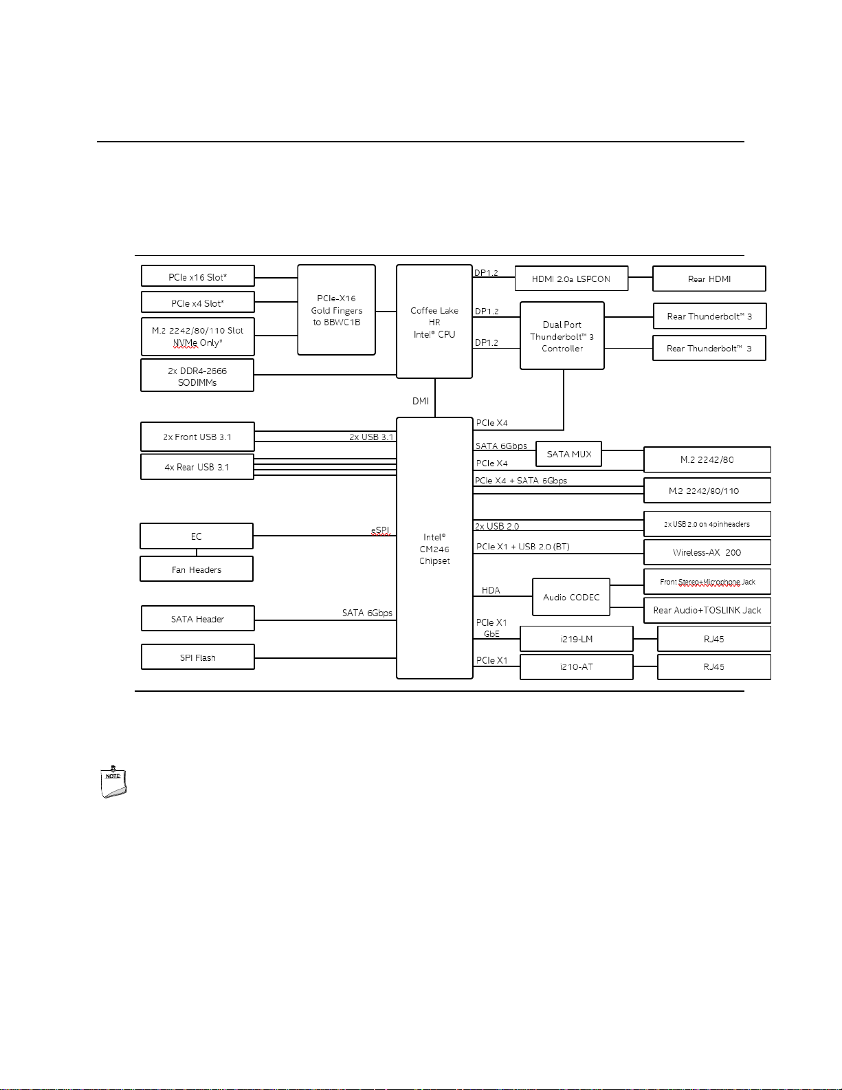
2.1 Block Diagram
Figure 1 is a block diagram of the major functional areas of the Intel® NUC 9 Extreme Kit and the
Intel® NUC 9 Pro Kit.
Figure 1. Block Diagram
NOTE
While the PCIe x16 slot, PCIe x4 slot, and M.2 2242/80/110 Slot NVMe Only devices are shown
connected to the BBWC1B they will share bandwidth when more than one device is connected due
to PCIe Bifurcation detailed in Table 6.
Page 18

18
2.2 Processor
Intel NUC 9 Extreme Kits feature the Intel NUC 9 Extreme Compute Element pre-installed into the
kit. All Intel NUC 9 Extreme Kits feature a 9th Gen Intel® Core™ processor with 45W TDP.
The NUC9i9QNX features the 9th Gen Intel Core i9-9980HK eight-core processor.
The NUC9i7QNX features the 9th Gen Intel Core i7-9750H six-core processor.
The NUC9i5QNX features the 9th Gen Intel Core i5-9300H quad-core processor.
• Intel® UHD Graphics 630
• Integrated memory controller
The Intel NUC 9 Pro Kit NUC9VXQNX features an Intel® Xeon™ E-2286M processor with a 45W
TDP.
• Intel® UHD Graphics P630
• Integrated memory controller
The Intel NUC 9 Pro Kit NUC9V7QNX features an Intel® Core™ i7-9850H processor with a 45W
TDP.
• Intel® UHD Graphics 630
• Integrated memory controller
2.3 Platform Controller Hub (PCH)
The Intel NUC 9 Extreme/Pro Kits feature a soldered-down Mobile Intel® CM246 Platform
Controller Hub with Direct Media Interface (DMI) interconnect providing interfaces to the
processor and the USB, SATA, LAN, PCI Express interfaces. The CM246 is a centralized controller
for the kit’s I/O paths.
2.3.1 Direct Media Interface (DMI)
Direct Media Interface (DMI) is the chip-to-chip connection between the processor and PCH. This
high-speed interface integrates advanced priority-based servicing allowing for concurrent traffic
and true isochronous transfer capabilities.
2.4 System Memory
The Intel NUC Extreme/Pro Kit has two 260-pin SO-DIMM sockets and supports the following
memory features:
• 1.2 V DDR4 SDRAM SO-DIMMs with gold plated contacts
• Two independent memory channels with interleaved mode support
• Unbuffered, single-sided or double-sided SO-DIMMs
• 64 GB maximum total system memory (with 16 Gb memory technology)
• Minimum recommended total system memory: 4096 MB
• Non-ECC SO-DIMMs (All NUC 9 Extreme/Pro Kits)
• ECC SO-DIMMs (NUC9VXQNX)
Page 19
Product Description
19
• Serial Presence Detect
• DDR4 2133/2400/2666 MHz SDRAM SO-DIMMs
• Intel® XMP support (NUC9i9QNX and NUC9i7QNX)
Supports 4 Gb, 8 Gb, and 16 Gb memory technology (SDRAM Density)
NOTE
To be fully compliant with all applicable DDR SDRAM memory specifications, the board should be
populated with SO-DIMMs that support the Serial Presence Detect (SPD) data structure. This
allows the BIOS to read the SPD data and program the chipset to accurately configure memory
settings for optimum performance. If non-SPD memory is installed, the BIOS will attempt to
correctly configure the memory settings, but performance and reliability may be impacted or the
SO-DIMMs may not function under the determined frequency.
NOTE
Intel NUC Extreme/Pro Kits support only 4 Gb, 8 Gb, and 16 Gb memory technologies (also referred
to as “SDRAM density”).
For information about…
Refer to:
Tested Memory
http://www.intel.com/NUCSupport
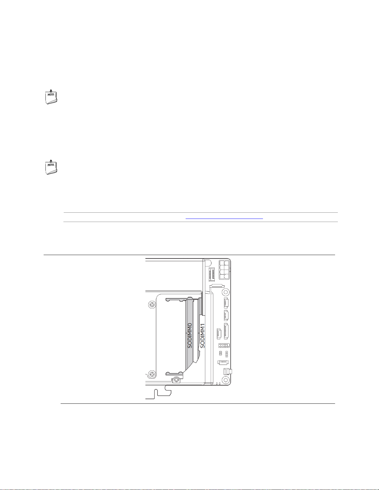
The SODIMM memory slots on the NUC 9 Extreme/Pro Kits is located underneath the NUC 9
Extreme/Pro Compute Element shroud door. See Figure 2.
Figure 2. SODIMM Location on NUC 9 Extreme/Pro Element
Page 20

20
2.4.1 Addressable Memory
The system has been validated with up to 64 GB of addressable system memory. Typically, the
address space that is allocated for PCI Express configuration space, BIOS (SPI Flash device), and
chipset overhead resides above the top of DRAM (total system memory). On a system that has 16
GB of system memory installed, it is not possible to use all of the installed memory due to system
address space being allocated for other system critical functions. These functions include the
following:
• BIOS/SPI Flash device (32 MB)
• Local APIC (19 MB)
• Direct Media Interface (40 MB)
• PCI Express configuration space (256 MB)
• PCH base address registers PCI Express ports (up to 256 MB)
• Memory-mapped I/O that is dynamically allocated for M.2 add-in cards (256 MB)
• Integrated graphics shared memory (up to 1.5 GB; 64 MB by default)
2.5 Processor Graphics Subsystem
The NUC Extreme/Pro Kit supports graphics through either the Intel® UHD Graphics 630 or Intel®
UHD Graphics P630.
For information about…
Refer to:
Intel Graphics Technologies
http://www.intel.com/graphics
2.5.1 Integrated Graphics
The NUC Extreme/Pro Kit supports integrated graphics via the processor.
2.5.1.1 High Definition Multimedia Interface* (HDMI*)
The HDMI port is HDMI 2.0a specification compliant and support standard, enhanced, or high
definition video, plus multi-channel digital audio on a single cable. The port is compatible with all
ATSC and DVB HDTV standards and supports thirty-two full range channels of lossless audio
formats. The system can support a display at the maximum supported resolution of 4096 x 2160
@ 60 Hz, 24bpp.
For information about
Refer to
HDMI technology
http://www.hdmi.org
2.5.1.1.1 Integrated Audio Provided by the HDMI Interfaces
The following audio technologies are supported by the HDMI 2.0a interface:
• 192kHz/16-bit or 176.4 kHz/24-bit, 32 Channel
Page 21

Product Description
21
2.5.1.1.2 High-bandwidth Digital Content Protection (HDCP)
The HDMI Port supports HDCP 2.2. HDCP is the technology for protecting high definition content
against unauthorized copy or interception between a source (computer, digital set top boxes, etc.)
and the sink (panels, monitor, and TVs). The PCH supports HDCP 2.2 for content protection over
wired displays.
2.5.1.2 DisplayPort* via Type C
DisplayPort is a digital communication interface that utilizes differential signaling to achieve a
high bandwidth bus interface designed to support connections between PCs and monitors,
projectors, and TV displays. DisplayPort is suitable for display connections between consumer
electronics devices such as high definition optical disc players, set top boxes, and TV displays.
The Type C DisplayPort connectors are compliant with the DisplayPort 1.2 specification and thus
have a maximum supported resolution of 4096 x 2160 @ 60Hz 24bpp.
DisplayPort output supports Multi-Stream Transport (MST) which allows for multiple
independent video streams (daisy-chain connection with multiple monitors) over a single
DisplayPort. This will require the use of displays that support DisplayPort 1.2 specification and
allow for this feature.
For information about
Refer to
DisplayPort technology
http://www.displayport.org
2.6 USB
The NUC 9 Extreme/Pro Kit supports eleven USB ports. All eleven ports are high-speed, fullspeed, and low-speed capable. The port arrangement is as follows:
• USB 3.1 Gen 2 ports:
⎯ Two ports are implemented with external front panel connectors (black)
⎯ Four ports are implemented with external back panel connectors (blue)
⎯ Two ports are implemented with as USB Type-C back panel connectors (black)
⎯ One port is implemented as an internal USB Type-A port in the front of the chassis.
• USB 2.0 ports:
⎯ Two ports via two single-port internal 1x4 1.25 mm pitch headers on NUC 9 Extreme/Pro
Compute Element (black in white outline space)
NOTE
Computer systems that have an unshielded cable attached to a USB port may not meet FCC
Class B requirements, even if no device is attached to the cable. Use a shielded cable that meets
the requirements for full-speed devices.
2.7 Storage Options
The NUC 9 Extreme/Pro Kit provides the following Storage interfaces:
Page 22

22
• Two internal M.2 NVMe/SATA slots supporting one M.2 2242/80 and one M.2 2242/80/110
(key type M) modules on NUC 9 Extreme/Pro Compute Element.
• One internal M.2 NVMe only slot located on the baseboard underneath the NUC 9
Extreme/Pro Element. Refer to Section 2.13.3 for the location of the baseboard M.2 slot.
• One SATA 6.0 Gb/s powered port (on NUC 9 Extreme/Pro Compute Element not usable on
the NUC 9 Extreme/Pro Kit)
The PCH provides independent SATA ports with a theoretical maximum transfer rate of 6 Gb/s. A
point-to-point interface is used for host to device connections.
2.7.1 AHCI Mode
The NUC 9 Extreme/Pro Kit supports AHCI storage mode.
NOTE
In order to use AHCI mode, AHCI must be enabled in the BIOS. Microsoft* Windows* 10 includes
the necessary AHCI drivers without the need to install separate AHCI drivers during the operating
system installation process; however, it is always good practice to update the AHCI drivers to the
latest available by Intel.
2.7.2 NVMe
The board supports M.2 NVM Express* (NVMe) drives. NVMe is an optimized, high-performance
scalable host controller interface designed to utilize PCIe-based solid-state storage. NVMe is
designed to provide efficient access to storage devices built with non-volatile memory, from
current NAND flash technology to future, higher performing persistent memory technologies like
Optane. NVMe is designed to meet serial bandwidth requirements and very high IOPs. It is based
on PCIe Gen 3 and can deliver up to 4GB/s bandwidth. Current NVMe is based on version 1.3 of
the specification.
2.7.3 Intel® Rapid Storage Technology / SATA RAID
The CM246 PCH supports Intel® Rapid Storage Technology, providing both AHCI and integrated
RAID functionality. The RAID capability provides high-performance RAID 0 and 1 functionality on
the M.2 Slots. Other RAID features include hot spare support, SMART alerting, and RAID 0 auto
replace. Software components include an Option ROM for pre-boot configuration and boot
functionality, a Microsoft Windows compatible driver, and a user interface for configuration and
management of the RAID capability of the PCH.
NOTE
Intel Rapid Storage Technology / SATA RAID is only supported if an M.2 SATA SSD module is
used with another M.2 SATA SSD module. RAID is not available when mixing an M.2 NVMe SSD
module and onboard SATA interface. CPU attached storage can also be used with NVMe SSD
RAID options, functionality of RAID from the PCH on the NUC 9 Extreme/Pro Compute Element
cannot be shared with functionality of RAID from the Baseboard. See Figure 3 for the M.2 Storage
location on the NUC 9 Extreme/Pro Compute Element.
Page 23
Product Description
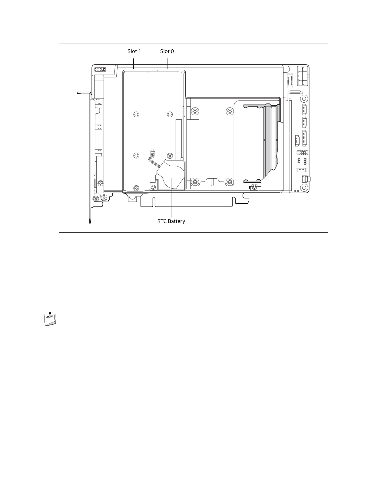
23
Figure 3. Location of NUC 9 Extreme/Pro Compute Element M.2 Slots and Battery
2.8 Real-Time Clock Subsystem
A coin-cell battery (CR2032) powers the real-time clock and CMOS memory. When the computer
is not plugged into a wall socket, the battery has an estimated life of three years. When the
computer is plugged in, the standby current from the power supply extends the life of the battery.
The clock is accurate to 13 minutes/year at 25 ºC with 3.3 VSB applied via the power supply 5 V
STBY rail.
NOTE
If the battery and AC power fail, date and time values will be reset and the user will be notified
during the POST.
When the voltage drops below a certain level, the BIOS Setup program settings stored in CMOS
RAM (for example, the date and time) might not be accurate. Replace the battery with an
equivalent one. Figure 3 shows the location of the battery.
2.9 LAN
The onboard LAN controllers consist of the following:
• Intel Gigabit Ethernet Controller I219-LM (10/100/1000 Mb/s)
• Intel Gigabit Ethernet Controller I210-AT (10/100/1000 Mb/s)
Page 24

24
• RJ-45 LAN connectors with integrated status LEDs
Additional features of the LAN subsystem include:
• CSMA/CD protocol engine
• LAN connect interface between the Processor and the LAN controller
• Power management capabilities
― ACPI technology support
― LAN wake capabilities
• LAN subsystem software
2.9.1 Intel® Gigabit Ethernet Controller I219-LM
The Intel Gigabit Ethernet Controller I219-LM supports the following features:
• Compliant with the 1 Gb/s Ethernet 802.3, 802.3u, 802.3z, 802.3ab specifications
• Multi-speed operation: 10/100/1000 Mb/s
• Full-duplex operation at 10/100/1000 Mb/s; Half-duplex operation at 10/100 Mb/s
• Flow control support compliant with the 802.3X specification as well as the specific operation
of asymmetrical flow control defined by 802.3z
• VLAN support compliant with the 802.1q specification
• Supports Jumbo Frames (up to 9 kB)
― IEEE 1588 supports (Precision Time Protocol)
• MAC address filters: perfect match unicast filters, multicast hash filtering, broadcast filter, and
promiscuous mode
2.9.2 Intel® Gigabit Ethernet Controller I210-AT
The Intel Gigabit Ethernet Controller I210-at supports the following features:
• Compliant with the 1 Gb/s Ethernet 802.3, 802.3u, 802.3z, 802.3ab specifications
• Multi-speed operation: 10/100/1000 Mb/s
• Full-duplex operation at 10/100/1000 Mb/s; Half-duplex operation at 10/100 Mb/s
• Flow control support compliant with the 802.3X specification as well as the specific operation
of asymmetrical flow control defined by 802.3z
• Supports Jumbo Frames (up to 9 kB)
― IEEE 1588 supports (Precision Time Protocol)
• MAC address filters: perfect match unicast filters, multicast hash filtering, broadcast filter, and
promiscuous mode
Page 25

Product Description
25
Figure 4. NUC 9 Extreme/Pro Kit LAN Controller Layout
2.9.3 LAN Software
LAN software and drivers are available from Intel’s World Wide Web site.
For information about
Refer to
Obtaining LAN software and drivers
http://downloadcenter.intel.com
2.10 Intel® Security and Manageability Technologies
Intel® Security and Manageability Technologies provides tools and resources to help small
business owners and IT organizations protect and manage their assets in a business or
institutional environment.
NOTE
Software with security and/or manageability capability is required to take advantage of Intel
platform security and/or management technologies.
Page 26

26
2.10.1 Intel® vPro™ Technology
Intel® vPro™ Technology is a collection of platform capabilities that support enhanced
manageability, security, virtualization and power efficiency. The key platform capabilities include:
• Intel® Active Management Technology (Intel® AMT) 12.0
• Intel® Virtualization (Intel® VT-x)
• Intel® Virtualization for Directed I/O (Intel® VT-d)
• Intel® Trusted Execution Technology (Intel® TXT)
• Intel® Identity Protection Technology (Intel® IPT)
• Intel® Software Guard Extensions (Intel® SGX)
• Intel® Transparent Supply Chain (Intel® TSC)
• Trusted Platform Module 2.0 (TPM)
For information about
Refer to
Intel® vPro Technology
http://support.intel.com/support/vpro/
2.10.1.1 Intel® Active Management Technology 12
When used with third-party management and security applications, Intel Active Management
Technology (Intel® AMT) allows business owners and IT organizations to better discover, heal, and
protect their networked computing assets.
Some of the features of Intel AMT include:
• Out-of-band (OOB) system access, to discover assets even while PCs are powered off
• Remote trouble-shooting and recovery, which allows remote diagnosis and recovery of
systems after OS failures
• Hardware-based agent presence checking that automatically detects and alerts when critical
software agents have been stopped or are missing
• Proactive network defense, which uses filters to block incoming threats while isolating
infected clients before they impact the network
• Remote hardware and software asset tracking, helping to track computer assets and keep
virus protection up-to-date
• Keyboard, video and mouse (KVM) remote control, which allows redirection of a managed
system’s video to a remote console which can then interact with it using the console’s own
mouse and keyboard
NOTE
Intel AMT requires a network connector and an Intel AMT enabled remote management console.
Setup requires additional configuration of the platform.
For information about
Refer to
Intel® Active Management Technology
http://www.intel.com/technology/platform-technology/intelamt/index.htm
Page 27

Product Description
27
2.10.1.2 Intel® Virtualization Technology
Intel® Virtualization Technology (Intel® VT-x) is a hardware-assisted technology that, when
combined with software-based virtualization solutions, provides maximum system utilization by
consolidating multiple environments into a single server or client.
NOTE
A processor with Intel VT does not guarantee that virtualization will work on your system. Intel VT
requires a computer system with a chipset, BIOS, enabling software and/or operating system,
device drivers, and applications designed for this feature.
For information about
Refer to
Intel® Virtualization Technology
http://www.intel.com/technology/virtualization/technology.htm
2.10.1.3 Intel® Virtualization Technology for Directed I/O
Intel® Virtualization Technology for Directed I/O (Intel® VT-d) allows addresses in incoming I/O
device memory transactions to be remapped to different host addresses. This provides Virtual
Machine Monitor (VMM) software with:
• Improved reliability and security through device isolation using hardware assisted remapping.
• Improved I/O performance and availability by direct assignment of devices.
For information about
Refer to
Intel® Virtualization Technology for Directed I/O
https://software.intel.com/enus/node/139035?wapkw=vt+directed+io
Page 28

28
2.10.1.4 Intel® Trusted Execution Technology
Intel® Trusted Execution Technology (Intel® TXT) is a hardware security solution that protects
systems against software-based attacks by validating the behavior of key components at startup
against a known good source. It requires that Intel VT be enabled and the presence of a TPM.
For information about
Refer to
Intel® Trusted Execution Technology
http://www.intel.com/content/www/us/en/architecture-andtechnology/trusted-execution-technology/malware-reductiongeneral-technology.html
2.10.1.5 Intel® Identity Protection Technology
Intel® Identity Protection Technology (Intel® IPT) provides a simple way for websites and
enterprises to validate that a user is logging in from a trusted computer. This is accomplished by
using the Intel Manageability Engine embedded in the chipset to generate a six-digit number that,
when coupled with a user name and password, will generate a One-Time Password (OTP) when
visiting Intel IPT-enabled websites. Intel IPT eliminates the need for the additional token or key fob
required previously for two-factor authentication.
For information about
Refer to
Intel® Identity Protection Technology
http://ipt.intel.com
2.10.1.6 Intel® Software Guard Extensions
Intel® Software Guard Extensions (Intel® SGX) is for application developers who are seeking to
protect select code and data from disclosure or modification. Intel SGX makes such protections
possible through the use of enclaves, which are protected areas of execution in memory.
Application code can be put into an enclave by special instructions and software made available
to developers via the Intel SGX Software Development Kit (SDK).
For information about
Refer to
Intel® Software Guard Extensions
https://software.intel.com/en-us/sgx
2.10.1.7 Intel® Transparent Supply Chain (TSC)
Intel® Transparent Supply Chain is being able to prove that all components used for Intel
products were sourced from approved manufacturers and purchased from authorized suppliers
or distributors. The components will be traceable to each finished goods serial number. TSC data
aids in the detection of counterfeit, gray market, and/or components that do not conform to spec.
For information about
Refer to
Intel® Transparent Supply Chain
https://tsc.intel.com/nuc
Page 29

Product Description
29
2.10.1.8 Trusted Platform Module (TPM)
The TPM version 2.0 component is specifically designed to enhance platform security above-and-
beyond the capabilities of today’s software by providing a protected space for key operations and
other security critical tasks. Using both hardware and software, the TPM protects encryption and
signature keys at their most vulnerable stages—operations when the keys are being used
unencrypted in plain-text form. The TPM shields unencrypted keys and platform authentication
information from software-based attacks.
NOTE
Support for TPM v2.0 requires a UEFI-enabled operating system, such as Microsoft Windows 10.
TCM 2.0-compliant device:
NationZ TCM-Z32H330TC TPM v2.0
Page 30

Page 31

31
2.11 Power Management
Power management is implemented at several levels, including:
• Software support through Advanced Configuration and Power Interface (ACPI)
• Hardware support:
⎯ Power Input
⎯ LAN wake capabilities
⎯ Wake from USB
2.11.1 ACPI
ACPI gives the operating system direct control over the power management and Plug and Play
functions of a computer. The use of ACPI with this board requires an operating system that
provides full ACPI support. ACPI features include:
• Plug and Play (including bus and device enumeration)
• Power management control of individual devices, add-in boards (some add-in boards may
require an ACPI-aware driver), video displays, and hard disk drives
• Methods for achieving less than 15-watt system operation in the power-on/standby
sleeping state
• A Soft-off feature that enables the operating system to power-off the computer
• Support for a front panel power and sleep mode switch
Table 3 lists the system states based on how long the power switch is pressed, depending on how
ACPI is configured with an ACPI-aware operating system.
Table 3. Effects of Pressing the Power Switch
If the system is in this state…
…and the power switch is
pressed for
…the system enters this state
Off
(ACPI G2/G5 – Soft off)
Less than four seconds
Power-on
(ACPI G0 – working state)
On
(ACPI G0 – working state)
Less than four seconds
Soft-off/Standby
(ACPI G1 – sleeping state)
Note
On
(ACPI G0 – working state)
More than six seconds
Fail safe power-off
(ACPI G2/G5 – Soft off)
Sleep
(ACPI G1 – sleeping state)
Less than four seconds
Wake-up
(ACPI G0 – working state)
Sleep
(ACPI G1 – sleeping state)
More than six seconds
Power-off
(ACPI G2/G5 – Soft off)
Note: Depending on power management settings in the operating system.
Page 32

32
2.11.1.1 System States and Power States
Under ACPI, the operating system directs all system and device power state transitions. The
operating system puts devices in and out of low-power states based on user preferences and
knowledge of how devices are being used by applications. Devices that are not being used can be
turned off. The operating system uses information from applications and user settings to put the
system as a whole into a low-power state.
Table 4 lists the power states supported by the board along with the associated system power
targets. See the ACPI specification for a complete description of the various system and power
states.
Table 4. Power States and Targeted System Power
Global States
Sleeping States
Processor
States
Device States
G0 – working state
S0 – working
C0 – working
D0 – working state.
G1 – sleeping state
S3 – Suspend to RAM.
Context saved to RAM.
No power
D3 – no power except for wake-up
logic.
G1 – sleeping state
S4 – Suspend to disk.
Context saved to disk.
No power
D3 – no power except for wake-up
logic.
G2/S5
S5 – Soft off. Context not
saved. Cold boot is required.
No power
D3 – no power except for wake-up
logic.
G3 – mechanical off
AC power is disconnected
from the computer.
No power to the system.
No power
D3 – no power for wake-up logic,
except when provided by battery
or external source.
Notes:
1. Total system power is dependent on the system configuration, including add-in boards and peripherals powered by
the system chassis’ power supply.
2. Dependent on the standby power consumption of wake-up devices used in the system.
Page 33

33
2.11.1.2 Wake-up Devices and Events
Table 5 lists the devices or specific events that can wake the computer from specific states.
Table 5. Wake-up Devices and Events
Devices/events that wake up the
system…
…from this sleep
state
Comments
Power switch
S3, S4, S51
RTC alarm
S3, S4, S51
Monitor to remain in sleep state
LAN
S3, S4, S5
1, 3
“S5 WOL after G3” must be supported;
monitor to remain in sleep state
WIFI
S3, S4, S5
1, 3
Monitor to remain in sleep state
Bluetooth
S31, S4
USB
S3, S4, S5
1, 2, 3
Wake S4, S5 controlled by BIOS option
(not after G3)
PCIE
S3, S4
Via WAKE; monitor to remain in sleep
state
HDMI CEC
S3, S4, S51
Emulates power button push
Notes:
1. S4 implies operating system support only.
2. Will not wake from Deep S4/S5. USB S4/S5 Power is controlled by BIOS. USB S5 wake is controlled by BIOS. USB S4
wake is controlled by OS driver, not just BIOS option.
3. Windows Fast startup will block wake from LAN and USB from S5.
NOTE
The use of these wake-up events from an ACPI state requires an operating system that provides
full ACPI support. In addition, software, drivers, and peripherals must fully support ACPI wake
events.
2.11.2 Hardware Support
The board provides several power management hardware features, including:
• Wake from Power Button signal
When resuming from an AC power failure, the computer returns to the power state
defined in the BIOS. Available states are “Power On”, “Stay Off”, and “Last State”.
• LAN wake capabilities
Enables remote wake-up of the computer through a network. The LAN subsystem
monitors network traffic at the Media Independent Interface. Upon detecting a Magic
Packet* frame, the LAN subsystem asserts a wake-up signal that powers up the computer.
• Wake from USB
USB bus activity wakes the computer from an ACPI S3 state (not after G3).
• +5 V Standby Power Indicator LED
The standby power indicator LED shows that power is still present even when the
computer appears to be off.
Page 34

34
NOTE
The use of Wake from USB from an ACPI state requires an operating system that provides full
ACPI support. Wake from USB requires the use of a USB peripheral that supports Wake from USB.
2.12 Audio Subsystem Software
Audio is supported through the HDMI 2.0a ports interface through the processor and supports
eight full range channels of lossless audio formats per port. When using an encoded format (such
as DTS-HD MA or Dolby True HD) the board supports a single 7.1 stream. When using an unencoded format the board supports 8 discrete, un-encoded channels per HDMI port
simultaneously, for a total of 16 discrete/un-encoded channels.
2.12.1 HDMI Audio Subsystem Software
HDMI Audio drivers are built into the Graphics driver and are available from Intel’s website.
For information about
Refer to
Obtaining NUC software and drivers
https://downloadcenter.intel.com
2.12.2 Stereo/TOSLINK HD Audio Subsystem Software
The integrated Realtek ALC audio subsystem supports the following features:
• Analog line-out/Analog Headphone/Analog Microphone (front panel jack)
• Analog stereo line-out/TOSLINK out (back panel jack)
― Analog Speakers only (Stereo)
― SPDIF optical output formats up to compressed 5.1/7.1
• Support for 44.1 kHz/48 kHz/96 kHz/192 kHz sample rates on all analog outputs
• Support for 44.1 kHz/48 kHz/96 kHz sample rates on all analog inputs
• Front Panel Audio Jack Support (see Figure 5 for 3.5 mm audio jack pin out):
― Speakers only (Stereo)
― Headphones only (Stereo)
― Microphone only (mono)
― Combo Headphone (Stereo)/Microphone (mono)
Pin Number
Pin Name
Description
1
Tip
Left Audio Out
2
Ring
Right Audio Out
3
Ring
Common/Ground
4
Sleeve
Audio In/MIC
Figure 5. 4-Pin 3.5 mm (1/8 inch) Audio Jack Pin Out
Page 35

35
2.13 Connectors, Headers, and Expansion
CAUTION
Only the following connectors and headers have overcurrent protection: back panel USB, front
panel USB, internal USB headers, PCI Express Slots, and M.2 slots.
All other connectors and headers are not overcurrent protected and should connect only to
devices inside the computer’s chassis, such as fans and internal peripherals. Do not use these
connectors or headers to power devices external to the computer’s chassis. A fault in the load
presented by the external devices could cause damage to the computer, the power cable, and the
external devices themselves.
Furthermore, improper connection of USB header single wire connectors may eventually overload
the overcurrent protection and cause damage to the board.
This section describes the board’s connectors and headers. The connectors and headers can be
divided into these groups:
• Front panel I/O connectors
• Back panel I/O connectors
• Baseboard connectors and headers
• Interior chassis connectors and headers
• NUC Element Extreme/Pro board connectors and headers
2.13.1 Front Panel Connectors
Figure 6 indicates the location of the front panel connectors present on the chassis.
Page 36

36
Item
Description
A
Power button (backlit)
B
UHS-II SDXC Reader
C D USB 3.1 Gen 2 Type A Ports (Black)
3.5mm Speaker/Headset
Figure 6. Front Panel Connectors
2.13.2 Back Panel Connectors
Figure 7 indicates the location of the back panel connectors present.
Page 37

37
Item
Description
A
Lan Connector 1/2 (Connector 1 is 210AT, Connector 2 is 219LM)
B
USB 3.1 Gen 2 Type A Ports
C
HDMI Port
D
Thunderbolt 3 ports
E
Stereo/TOSLINK combo jack
F
AC Power input (C13)
Figure 7. Back Panel Connectors
2.13.3 Baseboard Connectors
The NUC 9 Extreme/Pro Kit has a baseboard that expands the connectivity of the NUC 9
Extreme/Pro Compute Element through the usage of PCI Express lanes. Connectors that are used
for expansion through the NUC Element gold fingers to the Baseboard are shown in Table 6.
Figure 8 shows a top down view of all connectors and headers on the BBWC1B Baseboard.
Table 6. Intel BBWC1B Baseboard configuration
Connector Type
Description
PCIe 3.0 x16 Slot
The NUC Extreme/Pro Compute Element input connector (black)
PCIe 3.0 x4 M.2 Slot
M.2 slot that is configured for NVMe only (covered by heatsink)
PCIe 3.0 x16 Slot
PCIe 3.0 x16 standard compliant slot (blue)
PCIe 3.0 x4 Slot
PCIe 3.0 x4 standard compliant slot (black)
PCI Express Bifurcation Settings
PCIe 3.0 x16 Bifurcation supported to a maximum of three PCI Express devices (x8 + 2 x4)
Page 38

38
Item
Description
A
NUC 9 Extreme/Pro PCIe 3.0 x16 Slot input (black)
B
BBWC1B Power input connector
C
D
E
F
G
PCIe 3.0 x4 M.2 Slot 2242/2280/22110 NVMe only (with heatsink)
PCIe 3.0 x16 Slot (blue)
PCIe 3.0 x4 Slot (black)
PMBUS 5pin header
5VSTBY header (disconnected)
Figure 8. BBWC1B Baseboard Connectors
2.13.4 Interior Chassis Connectors
The bottom front portion of the NUC 9 Extreme/Pro chassis has interior headers that connect to
the NUC 9 Extreme/Pro Compute Element. Figure 9 shows a simplified view of the front panel
connectors.
Page 39

39
Item
Description
A
20pin Internal Desktop Type-C Key B Header
B
Internal Front Panel Audio Header
C Internal USB 3.1 Gen 2 Type A Port
Figure 9. NUC 9 Extreme/Pro Chassis Interior Front Panel Headers and Connectors
2.14 NUC 9 Extreme/Pro Element Headers and Connectors
The NUC 9 Extreme/Pro Compute Element contains headers and connectors necessary for
function inside the NUC 9 Extreme/Pro Kit. Figure 10 shows the headers and connectors that are
utilized by default and for expansion.
Page 40

40
Figure 10. NUC 9 Extreme/Pro Compute Element Headers and Connectors
Table 7. Components shown in Figure 10.
Item from
Figure 10
Description
A
Front Panel Audio Header
B
Internal USB 3.1 Gen 2 Type-C 20pin Header (Key B)
C
EPS 8 Pin Power Connector (see ATX Power Supply Specification Standard)
D
Internal FPC Style SATA/Power connector for optional 2.5in drive operation
E
USB 2.0 4 pin Header x 2
F
Internal CEC Pulse8 Header
G
Internal 8pin Dual PWM Fan header (note see Section 2.2 with information about power requirements)
H
9-pin Front Panel IO Header
I
3-pin BIOS Security Jumper
J
2-pin MEBX Reset Jumper
K
NUC Card 4pin PWM Fan Header
L
Power Button
M
NUC 9 Extreme/Pro Compute Element PCIe 3.0 x16 Gold Fingers
2.14.1 Signal Tables for Headers and Connectors
This section more clearly defines the pinouts and connector types used in Table 7.
Page 41

41
A - 10-pin Front Panel Audio Header
This connector is a 2 x 5 header with a 2.0mm pitch. The empty pin 8 is defined as the key.
A, Front Panel Audio Header
Pin
Number
Pin Definition - Signal
1
Port1L
2
Ground
3
Port1R
4
Presence#
5
Port2R
6
Sense1_Ret
7
Sense_Send
8
(EMPTY)
9
Port2L
10
Sense2_Ret
B - Internal USB 3.1 Gen 2 Type-C 20pin Header (Key B)
C, Internal USB 3.1 Gen 2 Type-C 20pin
Header (Key B)
Pin Number
Signal
Pin Number
Signal
1
Ground
11
Ground
2
TX1+
12
TX2- 3 TX1-
13
TX2+
4
Ground
14
Ground
5
RX1+
15
RX2- 6 RX1-
16
RX2+
7
Ground
17
Ground
8
D1+
18
D2+
9
D1-
19
D2-
10
VBUS
20
VBUS
C - EPS 8 Pin Power Connector
The EPS 8 Pin Power Connector follows the ATX standard layout and requirements. With one
side being Ground and the opposite side with the connector lock being 12V. The NUC 9
Extreme/Pro Compute element can utilize 12-19V input, while the NUC 9 Extreme/Pro Kit
provides the standard ATX 12V.
Page 42

42
D - Internal FPC Style SATA/Power connector for optional 2.5in drive operation
Note* This header is for use with the NUC 9 Extreme/Pro Compute Element only
D, Internal FPC SATA/Power connector, ZIF
FPC/FFC with lock.
Pin
Number
Signal
Pin
Number
Signal
1
+5V 2 +5V 3 +5V 4 +5V 5 NC 6 NC 7 NC 8 DEVSLP
9
GND
10
GND
11
SATA_RX_P
12
SATA_RX_N
13
GND
14
SATA_TX_N
15
SATA_TX_P
16
GND
E - USB 2.0 4 pin Header
Molex part number 53398-0471, 1.25mm Pitch PicoBlade* Header, Surface Mount, Vertical, LeadFree, 4 Circuits.
E, USB 2.0 Header
Pin
Number
Pin Definition - Signal
1
+5V DC power
2
D – Data
3
D + Data
4
Ground
F - Internal 8pin Dual PWM Fan header
Molex part number 53398-0867, 1.25mm Pitch PicoBlade* Header, Surface Mount, Vertical, Lead-
Free, 8 circuits.
G, Dual PWM Fan Header
Pin
Number
Pin Definition - Signal
1
Ground
2
Ground
Page 43

43
3
Tachometer 1
4
Pulse-Width Modulation (PWM) 1
5
Tachometer 2
6
Pulse-Width Modulation (PWM) 2
7
+12V DC Power
8
+12V DC Power
G - Internal CEC Pulse8 Header
Connector is a 1 x 4, 1.25mm pitch; Molex PicoBlade or equivalent size.
Molex part number 53398-0471, 1.25mm Pitch PicoBlade* Header, Surface Mount, Vertical, Lead-
Free, 4 Circuits.
H, Pulse 8 Header
Pin
Number
Pin Definition - Signal
1
5VSTBY
2
Ground
3
Power_Switch#
4
HDMI_CEC
H - 10-pin Front Panel IO Header
Connector is a 2 x 5, 2.0mm pitch connector.
I, Front Panel Header
Pin
Number
Signal Name
Description
1
HDD_POWER_LED
Pull-up 750Ω to +5V
2
POWER_LED_MAIN
[Out] Front panel LED (main color)
3
HDD_LED#
[Out] HDD activity LED
4
POWER_LED_ALT
[Out] Front panel LED (alt color)
5
GROUND
Ground
6
POWER_SWITCH#
[In] Power switch
7
RESET SWITCH#
[In] Reset switch
8
GROUND
Ground
9
+5V_DC (1A)(Vcc)
Power
10
Key (EMPTY)
No Pin
I - 3-pin BIOS Security Header
J, 3-pin BIOS Security Header
Pin Setting
BIOS Security setting behavior
Page 44

44
1 & 2
Pins 1&2: jumper position for Normal mode
2 & 3
Pins 2&3: jumper position for Lockdown mode
OPEN
No jumper: Recovery mode
J - 2-pin MEBX Reset Jumper
Note* This header is non-functional on the NUC 9 Extreme
K, 2-pin MEBX Reset Jumper
Pin Setting
BIOS Security setting behavior
Closed
Pins 1&2: jumper installed for RTCRST
OPEN
No jumper: Normal operation
K - NUC Card 4pin PWM Fan Header
L, NUC Blower 4pin PWM Header
Pin Number
Pin Definition - Signal
1
Ground
2
Tachometer
3
+12V
4
Pulse-Width Modulation (PWM)
2.15 Wireless Network Module
The Intel WI-FI 6 AX200 module provides hi-speed wireless connectivity provided with the
following capabilities:
• Compliant IEEE 802.11abgn, 802.11ac, 802.11ax, 802.11e, 802.11i, 802.11h, 802.11w
specifications
• Maximum bandwidth of 2.4Gbps
• Dual Mode Bluetooth* 5
• OS certified with : Microsoft Windows 10, Linux* (most features not available on Linux)
• Wi-Fi Direct* for peer to peer device connections
• Wi-Fi Miracast Source
• Intel® Wireless Display 6.0
• Wi-Fi Direct for peer to peer device connections
• Authentication: WPA and WPA2* Personal and Enterprise; WPA3*(Pending OS Support),
802.1X (EAP-TLS, TTLS, PEAP, LEAP, EAP-FAST), EAP-SIM, EAP-AKA
• Encryption: 64-bit and 128-bit WEP, AES-CCMP, 256-bit AES-GCM, TKIP
Page 45

45
• Intel® vPro™ Technology enabled on NUC9VXQNX and NUC9V7QNX
2.16 Antenna Connectors
The NUC 9 Extreme/Pro Kit wireless module has front panel internal antennas that connect to the
NUC 9 Extreme/Pro Compute Element MMCX style connectors. For wireless and Bluetooth
operation appropriate antennas will be required. Figure 11 shows the location of the two antenna
connectors on the NUC 9 Extreme/Pro Compute Element
Figure 11. Location of the Antenna Connectors
The wireless module on the NUC 9 Extreme/Pro Compute element is the Intel WIFI AX200D2WL
and uses a standard 2x2 mm size RF micro coaxial receptacle (connector) with an outer diameter of
1.5 mm as defined in the PCI-E M.2 Specification, the coaxial receptacle is then changed to the
MMCX Micromate style connector for more robust connection in chassis.
2.17 Internal Power Supply
The Intel® NUC 9 Extreme/Pro Kit has an internal power supply that takes in AC 100-240V and
outputs DC 12V, 3.3V, and 5Vsb. The form factor is compliant with the Flex-ATX specification.
The default power supply installed in the NUC 9 Extreme/Pro Kit is a FSP500-30AS 500W
80+Platinum rated supply.
Table 8. Power supply rating table.
Model No. FSP500-30AS
AC Input
100-240V~, 6-3A, 50-60Hz
DC Output
+3.3V
+12V
+5Vsb
Page 46

46
14.0A
40.41A
3.0A
485W Max
15W
Total output continuous shall not exceed
500W
The internal power supply FSP500-30AS 500W features the following cables:
• EPS12V 8pin power connector for Intel® NUC Extreme/Pro Element
• PCI Express 8pin right angle power connector*
• PCI Express 6+2pin straight power connector*
• PMBUS 5pin connector
NOTE
The PCI Express power connectors share a single power cable and are designed to be used
independently of each other.
CAUTION
Disconnect the attached AC power cable before you open or service the device. Installing or
removing devices from the Intel® NUC 9 Extreme/Pro Kit while a power source is connected to the
Kit may cause damage to the Intel® NUC 9 Extreme/Pro Kit, operating system corruption, create a
no boot condition or result in data loss.
2.18 Add-in Card Limitations
The Intel® NUC 9 Extreme/Pro Kit supports the installation of add-in PCIe cards. The PCI Express
3.0 x16 and 3.0 x4 connectors on the baseboard mentioned in Section 2.13.3 are designed to
accept PCI Express compliant devices. The table below demonstrates the maximum accepted
dimensions and specifications for add-in cards.
Table 9. PCI Express Add-in Cards Limitations
Dimensions
Add-in Card Type
Maximum Length
Maximum Width
Maximum Height
PCI Express 3.0 x16 Add-in
Card Dual Slot
202mm
Dual Slot Spec limit Total 39mm
(34.8mm Front components
+2.7mm rear backplate +1.7mm
PCB thickness)
131mm From Card edge to
absolute top most component
or cable of card
PCI Express 3.0 x16 Add-in
Card Single Slot
202mm
Single Slot
131mm From Card edge to
absolute top most component
or cable of card
PCI Express 3.0 x4 Add-in
Card Slot
202mm
Single Slot
131mm From Card edge to
absolute top most component
or cable of card
Page 47

47
NOTE* When a Dual Slot card is used in the PCIe x16 slot the PCIe x4 slot is inaccessible.
The maximum power consumption supported for add-in card design is 225W (150W from PCI Express
6+2/8pin + 75W from PCI Express Slot).
For a list of validated and compatible add-in cards go to the Inte® Product Compatibility Tool
https://compatibleproducts.intel.com/ProductDetails?activeModule=Intel%C2%AE%20NUC
2.19 NUC 9 Extreme/Pro Kit Dimensions
The following figures illustrate the mechanical form factor for the NUC 9 Extreme/Pro Kit. All
dimensions are shown in millimeters (mm).
Figure 12. Front Side
Page 48

48
Figure 13. Back Side
Page 49

49
Figure 14. Top Side
Page 50

50
Figure 15. Side Panel
2.20 Thermal Considerations
CAUTION
The NUC 9 Extreme/Pro Kit is designed to take in airflow from the bottom and sides through the
ventilated panels and exhausts through the top. Failure to ensure appropriate airflow may result
in reduced performance of both the processor and/or voltage regulator or, in some instances,
damage to the board.
All responsibility for determining the adequacy of any thermal or system design remains solely
with the system integrator. Intel makes no warranties or representations that merely following the
instructions presented in this document will result in a system with adequate thermal
performance.
CAUTION
Ensure that the ambient temperature does not exceed the board’s maximum operating
temperature. Failure to do so could cause components to exceed their maximum case temperature
Page 51

51
and malfunction. For information about the maximum operating temperature, see the
environmental specifications in Section Error! Reference source not found..
CAUTION
Ensure that proper airflow is maintained in the processor voltage regulator circuit. Failure to do
so may result in shorter than expected product lifetime.
2.21 Reliability
The demonstrated Mean Time Between Failures (MTBF) is done through 24/7 testing. Full Intel®
NUC systems in chassis with memory, SSD or HDD, and a fan are ran at 100% on time for 90 days
continuously while running system wide stress inducing software in a 35 °C ambient air
temperature chamber. The demonstrated MTBF for Intel NUC Extreme/Pro Kit is 50,000 hours.
Page 52

52
2.22 Environmental
Table 10 lists the environmental specifications for the Intel® NUC 9 Extreme/Pro Kit.
Table 10. Environmental Specifications
Parameter
Specification
Temperature
Sustained Storage
Limits (i.e. warehouse)
-20 C to +40 C
Short Duration Limits
(i.e. shipping)
-40 °C to +60 °C
Ambient Operating –
NUC Kit*
0 C to +35 C
* Processor performance may automatically decrease when the system exceeds ambient
operating temperature ranges above.
Shock (Board)
Unpackaged
25 g trapezoidal waveform
Velocity change of 170 inches/s²
Packaged
Free fall package drop machine set to the height determined by the weight of the package.
Product Weight (pounds)
Non-palletized Product
drop height (inches)
Palletized drop heights (single
product) (inches)
<20
36
N/A 21-40
30
N/A 41-80
24
N/A 81-100
18
12
100-120
12
9
Vibration (System)
Unpackaged
Random profile 5 Hz @ 0.001 g^2/Hz to 20 Hz @ 0.01 g^2/Hz(slope up)
20 Hz to 500 Hz @ 0.01 g^2/Hz (flat)
Input acceleration is 2.20g RMS
Packaged
Random profile 5 Hz @ 0.01 g^2/Hz to 20 Hz @ 0.02 g^2/Hz(slope up)
20 Hz to 500 Hz @ 0.02 g^2/Hz (flat)
Input acceleration is 3.13g RMS
Note: Before attempting to operate the Intel® NUC 9 Extreme/Pro Kit, the overall temperature of the system
must be above the minimum operating temperature specified. It is recommended that the system
temperature be at least room temperature before attempting to power on the NUC 9 Extreme/Pro Kit.
The operating and non-operating environment must avoid condensing humidity.
Page 53

53
3 Overview of BIOS Features
3.1 Introduction
The board uses Intel AMI BIOS core that is stored in the Serial Peripheral Interface Flash Memory
(SPI Flash) and can be updated using a disk-based program. The SPI Flash contains the Visual
BIOS Setup program, POST, the PCI auto-configuration utility, LAN EEPROM information, and
Plug and Play support.
The BIOS displays a message during POST identifying the type of BIOS and a revision code. The
initial production BIOSs are identified as TBD.
The Visual BIOS Setup program can be used to view and change the BIOS settings for the
computer. The BIOS Setup program is accessed by pressing the <F2> key after the Power-On
Self-Test (POST) memory test begins and before the operating system boot begins.
BIOS FLASH MEMORY ORGANIZATION
The Serial Peripheral Interface Flash Memory (SPI Flash) includes a 16 MB flash memory device.
3.2 System Management BIOS (SMBIOS)
SMBIOS is a Desktop Management Interface (DMI) compliant method for managing computers in
a managed network.
The main component of SMBIOS is the Management Information Format (MIF) database, which
contains information about the computing system and its components. Using SMBIOS, a system
administrator can obtain the system types, capabilities, operational status, and installation dates
for system components. The MIF database defines the data and provides the method for
accessing this information. The BIOS enables applications such as third-party management
software to use SMBIOS. The BIOS stores and reports the following SMBIOS information:
• BIOS data, such as the BIOS revision level
• Fixed-system data, such as peripherals, serial numbers, and asset tags
• Resource data, such as memory size, cache size, and processor speed
• Dynamic data, such as event detection and error logging
Non-Plug and Play operating systems require an additional interface for obtaining the SMBIOS
information. The BIOS supports an SMBIOS table interface for such operating systems. Using this
support, an SMBIOS service-level application running on a non-Plug and Play operating system
can obtain the SMBIOS information. Additional board information can be found in the BIOS under
the Additional Information header under the Main BIOS page.
3.3 Legacy USB Support
Legacy USB support enables USB devices to be used even when the operating system’s USB
drivers are not yet available. Legacy USB support is used to access the BIOS Setup program, and
Page 54

54
to install an operating system that supports USB. By default, Legacy USB support is set to
Enabled.
Legacy USB support operates as follows:
1. When you apply power to the computer, legacy support is disabled.
2. POST begins.
3. Legacy USB support is enabled by the BIOS allowing you to use a USB keyboard to enter and
configure the BIOS Setup program and the maintenance menu.
4. POST completes.
5. The operating system loads. While the operating system is loading, USB keyboards and mice
are recognized and may be used to configure the operating system. (Keyboards and mice are
not recognized during this period if Legacy USB support was set to Disabled in the BIOS
Setup program.)
6. After the operating system loads the USB drivers, all legacy and non-legacy USB devices are
recognized by the operating system, and Legacy USB support from the BIOS is no longer
used.
To install an operating system that supports USB, verify that Legacy USB support in the BIOS
Setup program is set to Enabled and follow the operating system’s installation instructions.
3.4 BIOS Updates
The BIOS can be updated using one of the following methods:
• Intel® Express BIOS Update utility, which enables automated updating while in the Windows
environment. Using this utility, the BIOS can be updated from a file on a hard disk, a USB
drive, a CD-ROM, or from the file location on the Web.
• Intel® F7 switch during POST allows a user to select where the BIOS Capsule file .CAP file is
located and perform the update from that location/device. Similar to performing a BIOS
Recovery without removing the BIOS configuration jumper. The F7 switch supports FAT,
FAT32, and NTFS format storage.
Both utilities verify that the updated BIOS matches the target system to prevent accidentally
installing an incompatible BIOS.
NOTE
Review the instructions distributed with the upgrade utility before attempting a BIOS update.
For information about
Refer to
BIOS update utilities
https://www.intel.com/content/www/us/en/support/articles/0000
05636/
3.4.1 Language Support
The BIOS Setup program and help messages are supported in US English. Check the Intel web
site for support.
Page 55

55
3.4.2 BIOS Recovery
It is unlikely that anything will interrupt a BIOS update; however, if an interruption occurs, the
BIOS could be damaged. Table 11 lists the drives and media types that can and cannot be used
for BIOS recovery. The BIOS recovery media does not need to be made bootable.
Table 11. Acceptable Drives/Media Types for BIOS Recovery
Media Type
(Note)
Can be used for BIOS recovery?
Hard disk drive (connected to SATA or USB)
Yes
CD/DVD drive (connected to USB)
Yes
USB flash drive
Yes
NOTE
Supported file systems for BIOS recovery:
• NTFS (sparse, compressed, or encrypted files are not supported)
• FAT32
• FAT16
• FAT12
• ISO 9660
For information about
Refer to
BIOS recovery
https://www.intel.com/content/www/us/en/support/articles/000033291/
Page 56

56
3.5 Boot Options
In the BIOS Setup program, the user can choose to boot from a hard drive, optical drive,
removable drive, or the network. The default setting is for the optical drive to be the first boot
device, the hard drive second, removable drive third, and the network fourth.
NOTE
Optical drives are not supported by the onboard SATA connectors. Optical drives are supported
only via the USB interfaces.
3.5.1 Network Boot
The network can be selected as a boot device. This selection allows booting from the onboard
LAN or a network add-in card with a remote boot ROM installed.
Pressing the <F12> key during POST automatically forces booting from the LAN. To use this key
during POST, the User Access Level in the BIOS Setup program's Security menu must be set to
Full.
3.5.2 Booting Without Attached Devices
For use in embedded applications, the BIOS has been designed so that after passing the POST,
the operating system loader is invoked even if the following devices are not present:
• Video cable
• Keyboard
• Mouse
3.5.3 Boot Device Selection During POST
Pressing the <F10> key during POST causes a boot device menu to be displayed. This menu
displays the list of available boot devices. Table 12 lists the boot device menu options.
Table 12. Boot Device Menu Options
Boot Device Menu Function Keys
Description
<> or <>
Selects a default boot device
<Enter>
Exits the menu, and boots from the selected device
<Esc>
Exits the menu and boots according to the boot priority defined
through BIOS setup
3.5.4 Power Button Menu
As an alternative to Back-to-BIOS Mode or normal POST Hotkeys, the user can use the power
button to access a menu. The Power Button Menu is accessible via the following sequence:
1. System is in S4/S5 (not G3)
2. User pushes the power button and holds it down for 3 seconds
Page 57

57
3. The system will emit three short beeps from the front panel (FP) audio port, then stop to
signal the user to release the power button. The FP power button LED will also change from
Blue to Amber when the user can release the power button.
4. User releases the power button before the 4-second shutdown override
If this boot path is taken, the BIOS will use default settings, ignoring settings in VPD where
possible.
At the point where Setup Entry/Boot would be in the normal boot path, the BIOS will display the
following prompt and wait for a keystroke:
[ESC] Normal Boot
[F2] Intel Visual BIOS
[F3] Disable Fast Boot
[F4] BIOS Recovery
[F7] Update BIOS
[F10] Enter Boot Menu
[F12] Network Boot
[F2] Enter Setup is displayed instead if Visual BIOS is not supported.
[F3] Disable Fast Boot is only displayed if at least one Fast Boot optimization is enabled.
If an unrecognized key is hit, then the BIOS will beep and wait for another keystroke. If one of the
listed hotkeys is hit, the BIOS will follow the indicated boot path. Password requirements must
still be honored.
If Disable Fast Boot is selected, the BIOS will disable all Fast Boot optimizations and reset the
system.
Page 58

58
3.6 Hard Disk Drive Password Security Feature
The Hard Disk Drive Password Security feature blocks read and write accesses to the hard disk
drive until the correct password is given. Hard Disk Drive Passwords are set in BIOS SETUP and
are prompted for during BIOS POST. For convenient support of S3 resume, the system BIOS will
automatically unlock drives on resume from S3. Valid password characters are A-Z, a-z, and 0-9.
Passwords may be up to 19 characters in length.
The User hard disk drive password, when installed, will be required upon each power-cycle until
the Master Key or User hard disk drive password is submitted.
The Master Key hard disk drive password, when installed, will not lock the drive. The Master Key
hard disk drive password exists as an unlock override in the event that the User hard disk drive
password is forgotten. Only the installation of the User hard disk drive password will cause a hard
disk to be locked upon a system power-cycle.
Table 13 shows the effects of setting the Hard Disk Drive Passwords.
Table 13. Master Key and User Hard Drive Password Functions
Password Set
Password During Boot
Neither
None
Master only
None
User only
User only
Master and User Set
Master or User
During every POST, if a User hard disk drive password is set, POST execution will pause with the
following prompt to force the user to enter the Master Key or User hard disk drive password:
“Enter Hard Disk Drive Password:”
Upon successful entry of the Master Key or User hard disk drive password, the system will
continue with normal POST.
If the hard disk drive password is not correctly entered, the system will go back to the above
prompt. The user will have three attempts to correctly enter the hard disk drive password. After
the third unsuccessful hard disk drive password attempt, the system will halt with the message:
“Hard Disk Drive Password Entry Error”
A manual power cycle will be required to resume system operation.
NOTE
As implemented on Intel NUC Extreme/Pro Kit, Hard Disk Drive Password Security is only
supported on either M.2 ports on the NUC 9 Extreme/Pro Compute Element. The passwords are
stored on the hard disk drive so if the drive is relocated to another computer that does not support
Hard Disk Drive Password Security feature, the drive will not be accessible.
3.7 BIOS Security Features
The BIOS includes security features that restrict access to the BIOS Setup program and who can
boot the computer. A supervisor password and a user password can be set for the BIOS Setup
program and for booting the computer, with the following restrictions:
Page 59

59
• The supervisor password gives unrestricted access to view and change all the Setup options
in the BIOS Setup program. This is the supervisor mode.
• The user password gives restricted access to view and change Setup options in the BIOS
Setup program. This is the user mode.
• If only the supervisor password is set, pressing the <Enter> key at the password prompt of
the BIOS Setup program allows the user restricted access to Setup.
• If both the supervisor and user passwords are set, users can enter either the supervisor
password or the user password to access Setup. Users have access to Setup respective to
which password is entered.
• Setting the user password restricts who can boot the computer. The password prompt will be
displayed before the computer is booted. If only the supervisor password is set, the
computer boots without asking for a password. If both passwords are set, the user can enter
either password to boot the computer.
• For enhanced security, use different passwords for the supervisor and user passwords.
• Valid password characters are A-Z, a-z, and 0-9. Passwords may be up to 16 characters in
length.
• To clear a set password, enter a blank password after entering the existing password.
Table 14 shows the effects of setting the supervisor password and user password. This table is for
reference only and is not displayed on the screen.
Table 14. Supervisor and User Password Functions
Password Set
Supervisor
Mode
User Mode
Setup Options
Password to
Enter Setup
Password
During Boot
Neither
Can change all
options
(Note)
Can change all
options
(Note)
None
None
None
Supervisor only
Can change all
options
Can change a
limited number
of options
Supervisor Password
Supervisor
None
User only
N/A
Can change all
options
Enter Password
Clear User Password
User
User
Supervisor and
user set
Can change all
options
Can change a
limited number
of options
Supervisor Password
Enter Password
Supervisor or
user
Supervisor or
user
Note: If no password is set, any user can change all Setup options.
Page 60

Page 61

Intel® NUC Extreme/Pro Kit Product Specification
61
3.8 Error Messages
3.8.1 BIOS Error Messages
Table 15 lists the error messages and provides a brief description of each.
Table 15. BIOS Error Messages
Error Message
Explanation
CMOS Battery Low
The battery may be losing power. Replace the battery soon.
CMOS Checksum Bad
The CMOS checksum is incorrect. CMOS memory may have been
corrupted. Run Setup to reset values.
Memory Size Decreased
Memory size has decreased since the last boot. If no memory was
removed, then memory may be bad.
No Boot Device Available
System did not find a device to boot.
4 Characterized Errata
This section of the document communicates product Errata for the Intel® NUC 9 Extreme Kit and
the Intel® NUC 9 Pro Kit.
Errata are design defects or deviations from current published specifications for a given product.
Published errata may or may not be corrected. Hardware and software designed to be used with
any given processor stepping must assume that all errata documented for that process stepping
are present on all devices.
There are no characterized errata at this time.
5 Regulatory Compliance and Battery
Disposal Information
5.1 Regulatory Compliance
This section contains the following regulatory compliance information for Intel NUC Board NUC 9
Extreme/Pro Kit with regulatory model NUC9QN:
• Safety standards
• European Union Declaration of Conformity statement
• Electromagnetic Compatibility (EMC) standards
• Product Ecology statements
• Regulatory Compliance Marks
Page 62

Intel® NUC Extreme/Pro Kit Product Specification
62
5.1.1 Safety Standards
Intel NUC 9 Extreme/Pro Kit with regulatory model NUC9QN complies with the safety standards
stated in Table 16 when correctly installed in a compatible host system.
Table 16. Safety Standards
Standard
Title
CSA/UL 60950-1
Information Technology Equipment – Safety - Part 1: General Requirements
(USA and Canada)
EN 60950-1
Information Technology Equipment – Safety - Part 1: General Requirements
(European Union)
IEC 60950-1
Information Technology Equipment – Safety - Part 1: General Requirements
(International)
EN62368-1
Information Technology Equipment – Safety - Part 1: General Requirements
(European Union)
5.1.2 European Union Declaration of Conformity Statement
We, Intel Corporation, declare under our sole responsibility that the products Intel® NUC 9
Extreme/Pro Kit with regulatory model NUC9QN is in conformity with all applicable essential
requirements necessary for CE marking, following the provisions of the European Council
Directive 2004/108/EC (EMC Directive), 2006/95/EC (Low Voltage Directive), and 2011/65/EU
(ROHS Directive).
The product is properly CE marked demonstrating this conformity and is for distribution within all
member states of the EU with no restrictions.
This product follows the provisions of the European Directives 2004/108/EC, 2006/95/EC, and
2011/65/EU.
Čeština Tento výrobek odpovídá požadavkům evropských směrnic 2004/108/EC, 2006/95/EC a
2002/95/EC.
Dansk Dette produkt er i overensstemmelse med det europæiske direktiv 2004/108/EC,
2006/95/EC & 2002/95/EC.
Dutch Dit product is in navolging van de bepalingen van Europees Directief 2004/108/EC,
2006/95/EC & 2002/95/EC.
Eesti Antud toode vastab Euroopa direktiivides 2004/108/EC, ja 2006/95/EC ja 2002/95/EC
kehtestatud nõuetele.
Suomi Tämä tuote noudattaa EU-direktiivin 2004/108/EC, 2006/95/EC & 2002/95/EC
määräyksiä.
Français Ce produit est conforme aux exigences de la Directive Européenne 2004/108/EC,
2006/95/EC & 2002/95/EC.
Deutsch Dieses Produkt entspricht den Bestimmungen der Europäischen Richtlinie
2004/108/EC, 2006/95/EC & 2002/95/EC.
Ελληνικά Το παρόν προϊόν ακολουθεί τις διατάξεις των Ευρωπαϊκών Οδηγιών 2004/108/EC,
2006/95/EC και 2002/95/EC.
Page 63

Intel® NUC Extreme/Pro Kit Product Specification
63
Magyar E termék megfelel a 2004/108/EC, 2006/95/EC és 2002/95/EC Európai Irányelv
előírásainak.
Icelandic Þessi vara stenst reglugerð Evrópska Efnahags Bandalagsins númer 2004/108/EC,
2006/95/EC, & 2002/95/EC.
Italiano Questo prodotto è conforme alla Direttiva Europea 2004/108/EC, 2006/95/EC &
2002/95/EC.
Latviešu Šis produkts atbilst Eiropas Direktīvu 2004/108/EC, 2006/95/EC un 2002/95/EC
noteikumiem.
Lietuvių Šis produktas atitinka Europos direktyvų 2004/108/EC, 2006/95/EC, ir 2002/95/EC
nuostatas.
Malti Dan il-prodott hu konformi mal-provvedimenti tad-Direttivi Ewropej 2004/108/EC,
2006/95/EC u 2002/95/EC.
Norsk Dette produktet er i henhold til bestemmelsene i det europeiske direktivet 2004/108/EC,
2006/95/EC & 2002/95/EC.
Polski Niniejszy produkt jest zgodny z postanowieniami Dyrektyw Unii Europejskiej
2004/108/EC, 206/95/EC i 2002/95/EC.
Portuguese Este produto cumpre com as normas da Diretiva Européia 2004/108/EC,
2006/95/EC & 2002/95/EC.
Español Este producto cumple con las normas del Directivo Europeo 2004/108/EC, 2006/95/EC
& 2002/95/EC.
Slovensky Tento produkt je v súlade s ustanoveniami európskych direktív 2004/108/EC,
2006/95/EC a 2002/95/EC.
Slovenščina Izdelek je skladen z določbami evropskih direktiv 2004/108/EC, 2006/95/EC in
2002/95/EC.
Svenska Denna produkt har tillverkats i enlighet med EG-direktiv 2004/108/EC, 2006/95/EC &
2002/95/EC.
Türkçe Bu ürün, Avrupa Birliği’nin 2004/108/EC, 2006/95/EC ve 2002/95/EC yönergelerine uyar.
5.1.3 EMC Regulations
Intel NUC 9 Extreme/Pro Kit with regulatory model NUC9QN complies with the EMC regulations
stated in Table 17 when correctly installed in a compatible host system.
Table 17. EMC Regulations
Regulation
Title
FCC 47 CFR Part 15, Subpart B
Title 47 of the Code of Federal Regulations, Part 15, Subpart B, Radio Frequency
Devices. (USA)
ICES-003
Interference-Causing Equipment Standard, Digital Apparatus. (Canada)
EN55032
Limits and methods of measurement of Radio Interference Characteristics of
Information Technology Equipment. (European Union)
EN55024
Information Technology Equipment – Immunity Characteristics Limits and methods
of measurement. (European Union)
EN55022
Australian Communications Authority, Standard for Electromagnetic Compatibility.
(Australia and New Zealand)
CISPR 32
Limits and methods of measurement of Radio Disturbance Characteristics of
Information Technology Equipment. (International)
Page 64

Intel® NUC Extreme/Pro Kit Product Specification
64
CISPR 24
Information Technology Equipment – Immunity Characteristics – Limits and Methods
of Measurement. (International)
VCCI-CISPR 32
Voluntary Control for Interference by Information Technology Equipment. (Japan)
KN-35, KN-24
Korean Communications Commission – Framework Act on Telecommunications and
Radio Waves Act (South Korea)
CNS 13438
Bureau of Standards, Metrology, and Inspection (Taiwan)
FCC Declaration of Conformity
This device complies with Part 15 of the FCC Rules. Operation is subject to the following two
conditions: (1) this device may not cause harmful interference, and (2) this device must accept
any interference received, including interference that may cause undesired operation.
For questions related to the EMC performance of this product, contact:
Intel Corporation, 5200 N.E. Elam Young Parkway, Hillsboro, OR 97124
1-800-628-8686
This equipment has been tested and found to comply with the limits for a Class B digital device,
pursuant to Part 15 of the FCC Rules. These limits are designed to provide reasonable protection
against harmful interference in a residential installation. This equipment generates, uses, and can
radiate radio frequency energy and, if not installed and used in accordance with the instructions,
may cause harmful interference to radio communications. However, there is no guarantee that
interference will not occur in a particular installation. If this equipment does cause harmful
interference to radio or television reception, which can be determined by turning the equipment
off and on, the user is encouraged to try to correct the interference by one or more of the
following measures:
• Reorient or relocate the receiving antenna.
• Increase the separation between the equipment and the receiver.
• Connect the equipment to an outlet on a circuit other than the one to which the receiver is
connected.
• Consult the dealer or an experienced radio/TV technician for help.
Any changes or modifications to the equipment not expressly approved by Intel Corporation
could void the user’s authority to operate the equipment.
Tested to comply with FCC standards for home or office use.
Canadian Department of Communications Compliance Statement
This digital apparatus does not exceed the Class B limits for radio noise emissions from digital
apparatus set out in the Radio Interference Regulations of the Canadian Department of
Communications.
Le présent appareil numerique német pas de bruits radioélectriques dépassant les limites
applicables aux appareils numériques de la classe B prescrites dans le Réglement sur le broullage
radioélectrique édicté par le ministére des Communications du Canada.
Japan VCCI Statement
Japan VCCI Statement translation: This is a Class B product based on the standard of the
Voluntary Control Council for Interference from Information Technology Equipment (VCCI). If this
is used near a radio or television receiver in a domestic environment, it may cause radio
interference. Install and use the equipment according to the instruction manual.
Page 65

Intel® NUC Extreme/Pro Kit Product Specification
65
Korea Class B Statement
Korea Class B Statement translation: This equipment is for home use, and has acquired
electromagnetic conformity registration, so it can be used not only in residential areas, but also
other areas.
5.1.4 e-Standby and ErP Compliance
Intel NUC 9 Extreme/Pro Kit with regulatory model NUC9QN meets the following program
requirements in an adequate system configuration, including appropriate selection of an efficient
power supply:
• EPEAT*
• Korea e-Standby
• European Union Energy-related Products Directive 2013 (ErP) Lot 6 and ErP Lot 3
For information about
Refer to
Electronic Product Environmental Assessment Tool (EPEAT)
http://www.epeat.net/
Korea e-Standby Program
http://www.kemco.or.kr/new_eng/pg02/pg02
100300.asp
European Union Energy-related Products Directive 2009 (ErP)
http://ec.europa.eu/enterprise/policies/sustai
nable-business/sustainable-productpolicy/ecodesign/index_en.htm
5.1.5 Regulatory Compliance Marks (Board Level)
Intel NUC 9 Extreme/Pro Kit with regulatory model NUC9QN has the regulatory compliance marks
shown in Table 18.
Table 18. Regulatory Compliance Marks
Description
Mark
UL joint US/Canada Recognized Component mark. Includes adjacent UL file number
for Intel NUC: E210882.
Page 66
Intel® NUC Extreme/Pro Kit Product Specification
66
FCC Declaration of Conformity logo mark for Class B equipment.
CE mark. Declaring compliance to the European Union (EU) EMC directive, Low
Voltage directive, and RoHS directive.
For CE Mark-Related Questions:
Intel Corporation
Attn: Corporate Quality
2200 Mission College Blvd.
Santa Clara, CA 95054-1549
USA
Australian Communications Authority (ACA) and New Zealand Radio Spectrum
Management (NZ RSM) C-tick mark. Includes adjacent Intel supplier code number,
N-232.
Japan VCCI (Voluntary Control Council for Interference) mark.
Korea Certification mark. Includes an adjacent MSIP (Ministry of Science, ICT &
Future Planning) certification number: MSIP-REM-CPU-NUC5i5MYBE
Taiwan BSMI (Bureau of Standards, Metrology and Inspections) mark. Includes
adjacent Intel company number, D33025.
D33025
RoHS
Printed wiring board manufacturer’s recognition mark. Consists of a unique UL
recognized manufacturer’s logo, along with a flammability rating (solder side).
Depedent upon the rating material.
V-0 or V-1
China RoHS/Environmentally Friendly Use Period Logo: This is an example of the
symbol used on Intel NUC and associated collateral. The color of the mark may vary
depending upon the application. The Environmental Friendly Usage Period (EFUP)
for Intel NUC has been determined to be 10 years.
Page 67

Intel® NUC Extreme/Pro Kit Product Specification
67
5.2 Battery Disposal Information
CAUTION
Risk of explosion if the battery is replaced with an incorrect type. Batteries should be recycled
where possible. Disposal of used batteries must be in accordance with local environmental
regulations.
PRÉCAUTION
Risque d'explosion si la pile usagée est remplacée par une pile de type incorrect. Les piles
usagées doivent être recyclées dans la mesure du possible. La mise au rebut des piles usagées
doit respecter les réglementations locales en vigueur en matière de protection de l'environnement.
FORHOLDSREGEL
Eksplosionsfare, hvis batteriet erstattes med et batteri af en forkert type. Batterier bør om muligt
genbruges. Bortskaffelse af brugte batterier bør foregå i overensstemmelse med gældende
miljølovgivning.
OBS!
Det kan oppstå eksplosjonsfare hvis batteriet skiftes ut med feil type. Brukte batterier bør kastes i
henhold til gjeldende miljølovgivning.
VIKTIGT!
Risk för explosion om batteriet ersätts med felaktig batterityp. Batterier ska kasseras enligt de
lokala miljövårdsbestämmelserna.
VARO
Räjähdysvaara, jos pariston tyyppi on väärä. Paristot on kierrätettävä, jos se on mahdollista.
Käytetyt paristot on hävitettävä paikallisten ympäristömääräysten mukaisesti.
VORSICHT
Bei falschem Einsetzen einer neuen Batterie besteht Explosionsgefahr. Die Batterie darf nur durch
denselben oder einen entsprechenden, vom Hersteller empfohlenen Batterietyp ersetzt werden.
Entsorgen Sie verbrauchte Batterien den Anweisungen des Herstellers entsprechend.
AVVERTIMENTO
Esiste il pericolo di un esplosione se la pila non viene sostituita in modo corretto. Utilizzare solo
pile uguali o di tipo equivalente a quelle consigliate dal produttore. Per disfarsi delle pile usate,
seguire le istruzioni del produttore.
Page 68

Intel® NUC Extreme/Pro Kit Product Specification
68
PRECAUCIÓN
Existe peligro de explosión si la pila no se cambia de forma adecuada. Utilice solamente pilas
iguales o del mismo tipo que las recomendadas por el fabricante del equipo. Para deshacerse de
las pilas usadas, siga igualmente las instrucciones del fabricante.
WAARSCHUWING
Er bestaat ontploffingsgevaar als de batterij wordt vervangen door een onjuist type batterij.
Batterijen moeten zoveel mogelijk worden gerecycled. Houd u bij het weggooien van gebruikte
batterijen aan de plaatselijke milieuwetgeving.
ATENÇÃO
Haverá risco de explosão se a bateria for substituída por um tipo de bateria incorreto. As baterias
devem ser recicladas nos locais apropriados. A eliminação de baterias usadas deve ser feita de
acordo com as regulamentações ambientais da região.
AŚCIAROŽZNAŚĆ
Існуе рызыка выбуху, калі заменены акумулятар неправільнага тыпу. Акумулятары
павінны, па магчымасці, перепрацоўвацца. Пазбаўляцца ад старых акумулятараў патрэбна
згодна з мясцовым заканадаўствам па экалогіі.
UPOZORNÌNÍ
V případě výměny baterie za nesprávný druh může dojít k výbuchu. Je-li to možné, baterie by
měly být recyklovány. Baterie je třeba zlikvidovat v souladu s místními předpisy o životním
prostředí.
Προσοχή
Υπάρχει κίνδυνος για έκρηξη σε περίπτωση που η μπαταρία αντικατασταθεί από μία λανθασμένου
τύπου. Οι μπαταρίες θα πρέπει να ανακυκλώνονται όταν κάτι τέτοιο είναι δυνατό. Η απόρριψη των
χρησιμοποιημένων μπαταριών πρέπει να γίνεται σύμφωνα με τους κατά τόπο περιβαλλοντικούς
κανονισμούς.
VIGYÁZAT
Ha a telepet nem a megfelelő típusú telepre cseréli, az felrobbanhat. A telepeket lehetőség szerint
újra kell hasznosítani. A használt telepeket a helyi környezetvédelmi előírásoknak megfelelően
kell kiselejtezni.
Page 69
Intel® NUC Extreme/Pro Kit Product Specification
69
AWAS
Risiko letupan wujud jika bateri digantikan dengan jenis yang tidak betul. Bateri sepatutnya
dikitar semula jika boleh. Pelupusan bateri terpakai mestilah mematuhi peraturan alam sekitar
tempatan.
OSTRZEŻENIE
Istnieje niebezpieczeństwo wybuchu w przypadku zastosowania niewłaściwego typu baterii.
Zużyte baterie należy w miarę możliwości utylizować zgodnie z odpowiednimi przepisami ochrony
środowiska.
PRECAUŢIE
Risc de explozie, dacă bateria este înlocuită cu un tip de baterie necorespunzător. Bateriile trebuie
reciclate, dacă este posibil. Depozitarea bateriilor uzate trebuie să respecte reglementările locale
privind protecţia mediului.
ВНИМАНИЕ
При использовании батареи несоответствующего типа существует риск ее взрыва.
Батареи должны быть утилизированы по возможности. Утилизация батарей должна
проводится по правилам, соответствующим местным требованиям.
UPOZORNENIE
Ak batériu vymeníte za nesprávny typ, hrozí nebezpečenstvo jej výbuchu.
Batérie by sa mali podľa možnosti vždy recyklovať. Likvidácia použitých batérií sa musí vykonávať
v súlade s miestnymi predpismi na ochranu životného prostredia.
POZOR
Zamenjava baterije z baterijo drugačnega tipa lahko povzroči eksplozijo.
Če je mogoče, baterije reciklirajte. Rabljene baterije zavrzite v skladu z lokalnimi okoljevarstvenimi
predpisi.
UYARI
Yanlış türde pil takıldığında patlama riski vardır. Piller mümkün olduğunda geri
dönüştürülmelidir. Kullanılmış piller, yerel çevre yasalarına uygun olarak atılmalıdır.
OСТОРОГА
Використовуйте батареї правильного типу, інакше існуватиме ризик вибуху.
Якщо можливо, використані батареї слід утилізувати. Утилізація використаних батарей
має бути виконана згідно місцевих норм, що регулюють охорону довкілля.
Page 70

Intel® NUC Extreme/Pro Kit Product Specification
70
 Loading...