

Page 1

Intel® Core™ 2 Duo Mobile Processors on 45-nm process for Embedded Applications
Thermal Design Guide
June 2008
Order Number: 320028-001
Page 2

INFORMATION IN THIS DOCUMENT IS PROVIDED IN CONNECTION WITH INTEL® PRODUCTS. EXCEPT AS PROVIDED IN INTEL’S TERMS AND
CONDITIONS OF SALE FOR SUCH PRODUCTS, INTEL ASSUMES NO LIABILITY WHATSOEVER, AND INTEL DISCLAIMS ANY EXPRESS OR IMPLIED
WARRANTY RELATING TO SALE AND/OR USE OF INTEL PRODUCTS, INCLUDING LIABILITY OR WARRANTIES RELATING TO FITNESS FOR A PARTICULAR
PURPOSE, MERCHANTABILITY, OR INFRINGEMENT OF ANY PATENT, COPYRIGHT, OR OTHER INTELLECTUAL PROPERTY RIGHT.
Intel Corporation may have patents or pending patent applications, trademarks, copyrights, or other intellectual property rights that relate to the
presented subject matter. The furnishing of documents and other materials and information does not provide any license, express or implied, by estoppel
or otherwise, to any such patents, trademarks, copyrights, or other intellectual property rights.
Intel products are not intended for use in medical, life saving, life sustaining, critical control or safety systems, or in nuclear facility applications.
Intel may make changes to specifications and product descriptions at any time, without notice.
Designers must not rely on the absence or characteristics of any features or instructions marked “reserved” or “un defined.” Intel reserves these for
future definition and shall have no responsibility whatsoever for conflicts or incompatibilities arising from future changes to them.
The Intel® Core™ 2 Duo Mobile Processors on 45-nm process for Embedded Applications may contain design defects or errors known as errata which
may cause the product to deviate from published specifications. Current characterized errata are available on request.
Contact your local Intel sales office or your distributor to obtain the latest specifications and before placing your product order.
Copies of documents which have an ordering number and are referenced in this document, or other Intel literature may be obtained by calling
1-800-548-4725 or by visiting Intel's website at http://www.intel.com.
AnyPoint, AppChoice, BoardWatch, BunnyPeople, CablePort, Celeron, Chips, CT Media, Dialogic, DM3, EtherExpress, ETOX, FlashFile, i386, i486, i960,
iCOMP , InstantIP, Intel, Intel Centrino, Intel logo, Intel386, Intel486, Intel740, IntelDX2, IntelDX4, IntelSX2, Intel Create & Share, Intel GigaBlade, Intel
InBusiness, Intel Inside, Intel Inside logo, Intel NetBurst, Intel NetMerge, Intel NetStructure, Intel Play, Intel Play logo, Intel Sing leDriver, Intel
SpeedStep, Intel StrataFlash, Intel TeamStation, Intel Xeon, Intel XScale, IPLink, Itanium, MCS, MMX, MMX logo, Optimizer logo, OverDrive, P arago n, PC
Dads, PC Parents, PDCharm, Pentium, Pentium II Xeon, Pentium III Xeon, Performance at Your Command, RemoteExpress, SmartDie, Solutions960,
Sound Mark, StorageExpress, The Computer Inside., The Journey Inside, TokenExpress, VoiceBrick, VTune, and Xircom are trademarks or registered
trademarks of Intel Corporation or its subsidiaries in the United States and other countries.
*Other names and brands may be claimed as the property of others.
Copyright © 2008, Intel Corporation. All Rights Reserved.
Intel® Core™ 2 Duo Mobile Processors on 45-nm process for Embedded Applications
TDG June 2008
2 Order Number: 320028-001
Page 3

Core™ 2 Duo Mobile Processors—Contents
Contents
1.0 Introduction ............................................................................................................. 6
1.1 Design Flow ......... .......................... .. ......................... .. .......................... .. ........... 6
1.2 Definition of Terms ..................................... .......................... .. .. .. ........................ 7
1.3 Reference Documents.......................................................................................... 8
1.4 Thermal Design Tool Availability ........................................................................... 8
2.0 Package Information ................................................................................................ 9
3.0 Thermal Specifications.............................................................................................10
3.1 Thermal Design Power.......................................... .. ......................... .. .................10
3.2 Maximum Allowed Component Temperature ..........................................................10
4.0 Mechanical Specifications ........................................................................................11
4.1 Package Mechanical Requirements.......................................................................11
4.1.1 Die Pressure/Load Upper Limit..................................................................11
4.1.2 Die Pressure/Load Lower Limit..................................................................11
4.2 Package Keep Out Zones Requirements................................................................11
4.3 Board Level Keep Out Zone Requirements .............................................................11
5.0 Thermal Solution Requirements...............................................................................15
5.1 Thermal Solution Characterization........................................................................15
5.1.1 Calculating the Required Thermal Performance for the Intel
processor ..............................................................................................16
6.0 Reference Thermal Solutions ...................................................................................18
6.1 ATCA Reference Thermal Solution................................ .. .. ............................ ........18
6.2 Keep Out Zone Requirements..............................................................................19
6.3 Thermal Performance................................................... .. .. .......................... .. .. ....19
6.4 1U+ Reference Heatsink.....................................................................................19
6.4.1 Keep Out Zone Requirements...................................................................20
6.4.2 Thermal Performance.............................. .. .. .. ......................... .. ...............20
6.5 Compact PCI Reference Heatsink .........................................................................21
6.5.1 Keep Out Zone Requirements...................................................................22
6.5.2 Thermal Performance.............................. .. .. .. ......................... .. ...............22
6.6 Heatsink Fastener Assembly................................................................................22
6.7 Thermal Interface Material (TIM) ................................................................... .. .. ..22
6.8 Heatsink Orientation ..........................................................................................23
7.0 Thermal Metrology...................................................................................................24
7.1 Die Temperature Measurements ..........................................................................24
7.2 Power Simulation Software .................................................................................24
7.3 Additional Thermal Features......................... .. ... ......................... .. .......................24
7.4 Local Ambient Temperature Measurement Guidelines..............................................24
7.4.1 Active Heatsink Measurements .................................................................25
7.4.2 Passive Heatsink Measurements................................................................25
8.0 Reliability Guidelines ...............................................................................................28
A Thermal Solution Component Suppliers....................................................................29
B Mechanical Drawings ...............................................................................................30
®
Core™2 Duo
Intel® Core™ 2 Duo Mobile Processors on 45-nm process-Thermal Design Guide
TDG June 2008
3 Order Number: 320028-001
Page 4

Figures—Core™ 2 Duo Mobile Processors
Figures
1 Thermal Design Process..............................................................................................7
2 Primary Side Keep Out Zone Requirements— Micro-FCPGA ............................................12
3 Primary Side Keep Out Zone Requirements— Micro-FCBGA............................................13
4 Secondary Side Keep Out Zone Requirements............................................. ... ..............14
5 Processor Thermal Characterization Parameter Relationships .........................................16
6 AdvancedTCA* Reference Heatsink Assembly...............................................................18
7 AdvancedTCA* Heatsink Thermal Performance vs. Volumetric Airflow Rate .................. .. ..19
8 1U Reference Heatsink Assembly .................................................... ...........................20
9 1U Heatsink Thermal Performance vs. Volumetric Airflow Rate .......................................21
10 CompactPCI Reference Heatsink Assembly ..................................................................21
11 cPCI Reference Heatsink Thermal Performance vs. Volumetric Flow Rate .........................22
12 Heatsink Orientation Relative to Airflow Direction .........................................................23
13 Measuring TLA with an Active Heatsink .......................................................................26
14 Measuring TLA with a Passive Heatsink .......................................................................27
15 AdvancedTCA* Reference Heatsink PCB Keep Out Zone Requirements (Sheet 1 of 2) ........ 31
16 AdvancedTCA* Reference Heatsink PCB Keep Out Zone Requirements (Sheet 2 of 2) ........ 32
17 AdvancedTCA* Reference Heatsink Assembly...............................................................33
18 AdvancedTCA* Reference Heatsink.............................................................................34
19 CompactPCI* Reference Heatsink PCB Keep Out Zone Requirements (Sheet 1 of 2).......... 35
20 CompactPCI* Reference Heatsink PCB Keep Out Zone Requirements (Sheet 2 of 2).......... 36
21 CompactPCI* Reference Heatsink Assembly................................ .. .. ........................... ..37
22 CompactPCI* Reference Heatsink...............................................................................38
23 1U Reference Heatsink PCB Keep Out Requirements (Sheet 1 of 2).................................39
24 1U Reference Heatsink PCB Keep Out Requirements (Sheet 2 of 2).................................40
25 1U Reference Heatsink Assembly ................................................ .. .. .. .........................41
26 1U Reference Heatsink..............................................................................................42
Tables
1 Definition of Terms.....................................................................................................7
2 Thermal Specifications for the Intel
3 Required Heatsink Thermal Performance (ΨJA).............................................................17
4 Reliability Requirements............................................................................................28
5 Reference Heatsink ..................................................................................................29
6 Mechanical Drawings..................................... .. .. .......................... .. .. .........................30
®
Core™2 Duo processor..........................................10
June 2008 TDG
Order Number: 320028-001 4
Intel® Core™ 2 Duo Mobile Processors on 45-nm process for Embedded Applications
Page 5

Revision History
Date Revision Description
June 2008 1.0 First Public release.
Core™ 2 Duo Mobile Processors—Tables
Intel® Core™ 2 Duo Mobile Processors on 45-nm process-Thermal Design Guide
TDG June 2008
5 Order Number: 320028-001
Page 6

Introduction—Core™ 2 Duo Mobile Processors
1.0 Introduction
The power dissipation of electronic components has risen along with the increase in complexity of
computer systems. T o ensure quality, reliability, and performance goals are met ov er the product’s life
cycle, the heat generated by the device must be properly dissipated. Typical methods to improve heat
dissipation include selective use of airflow ducting, and/or the use of heatsinks.
The goals of this document are to:
• Identify the thermal and mechanical specification for the device.
• Describe a reference thermal solution that meets the specifications.
A properly designed thermal solution will adequately cool the device at or below the thermal
specification. This is accomplished by providing a suitable local-ambient temperature, ensuring
adequate local airflow, and minimizing the die to local-ambient thermal resistance. Operation outside
the functional limits can degrade system performance and may cause permanent changes in the
operating characteristics of the component.
This document describes thermal design guidelines for the Intel® Core™ 2 Duo Mobile Processors on
45-nm process for Embedded Applications in the micro Flip Chip Pin Grid Array (micro-FCPGA)
package and the micro Flip Chip Ball Grid Array (micro-FCBGA) package. The information provided in
this document is for reference only and additional validation must be performed prior to implementing
the designs into final production. The intent of this document is to assist each original equipment
manufacturer (OEM) with the development of thermal solutions for their individual designs. The final
heatsink solution, including the heatsink, attachment method, and thermal interface material (TIM)
must comply with the mechanical design, environmental, and reliability requirements delineated in
the processor datasheet. It is the responsibility of each OEM to validate the thermal solution design
with their specific applications.
This document addresses thermal and mechanical design specifications for the Intel Core 2 Duo
processor only. For thermal design information on other Intel components, refer to the respective
component datasheets.
1.1 Design Flow
Several tools are available from Intel to assist with the development of a reliable, cost-effective
thermal solution. Figure 1 illustrates a typical thermal solution design process with available tools
noted. The tools are available through your local Intel field sales representative.
June 2008 TDG
Order Number: 320028-001 6
Intel® Core™ 2 Duo Mobile Processors on 45-nm process for Embedded Applications
Page 7
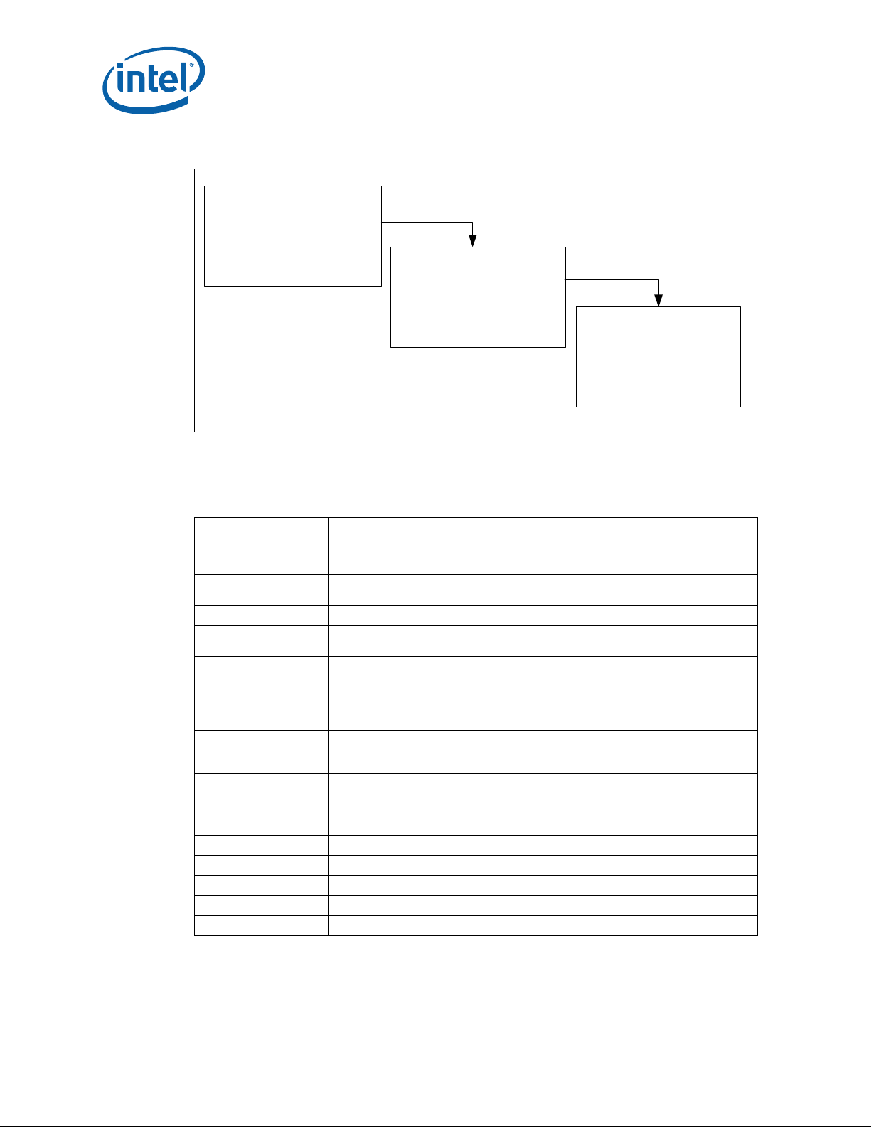
Figure 1. Thermal Design Process
Step 1: Thermal Simulation
Core™ 2 Duo Mobile Processors—Introduction
• P ackage Level Thermal Models
• Therm al Model User’s Guide
Step 2: Heatsink Design
and Selection
• Reference Heatsinks
• Ref erence Mounting Hardware
• Vendor Contacts
1.2 Definition of Terms
Table 1. Definition of Terms (Sheet 1 of 2)
Term Definition
FCPGA
FCBGA
T
JUNCTION-MAX
TDP
T
LA
Ψ
JA
Ψ
TIM
Ψ
SA
°C Degrees in Celsius
CFM Volumetric airflow rate in cubic feet per minute
in. Inches
LFM Airflow velocity in linear feet per minute
PCB Printed circuit board
T
SINK
Flip Chip Pin Grid Array. A pin grid array packaging tech nology where the die is
exposed on the package substrate.
Flip Chip Ball Grid Array. A ball grid array packaging technology where the die is
exposed on the package substrate.
Maximum allowed component (junction) temperature. Also referred to as T
Thermal Design Power. Thermal solutions should be designed to dissipate this
target power level.
Local ambient temperature. This is the temperature measured inside the chassis,
approximately 1 inch upstream of a component heatsink. Also referred to as T
Junction-to-ambient thermal characterization parameter. A measure of heatsink
thermal performance using the total package power. Defined as (T
Total Package Power
Thermal interface material thermal characterization parameter. A measure of
thermal interface material performance using total package power. Defined as (T
– T
CASE
Sink-to-ambient thermal characterization parameter. A measure of heatsink
thermal performance using total package power. Defined as (T
Total Package Power.
Heatsink temperature measured on the underside of the heatsink base.
)/ Total Package Power. Also referred to as Ψ
JUNCTION
Step 3: Thermal Validation
• Thermal Testing Software
• Thermal Test Vehicle
• User Guides
J-MAX
.
A
– T
– TLA) /
JUNCTION
)/
JUNCTION
JS.
SINK
Intel® Core™ 2 Duo Mobile Processors on 45-nm process-Thermal Design Guide
TDG June 2008
7 Order Number: 320028-001
Page 8

Introduction—Core™ 2 Duo Mobile Processors
Table 1. Definition of Terms (Sheet 2 of 2)
Term Definition
TIM
U
WWatt
Thermal Interface Material – the thermally conductive compound between the
heatsink and die. This material fills air gaps and voids, and enhances spreading of
the heat from the die to the heatsink.
A unit of measure used to define server rack spacing height. 1U is equal to 1.75
inches, 2U equals 3.50 inches, etc.
1.3 Reference Documents
The reader of this specification should also be familiar with material and concepts presented in the
following documents:
• Intel® Core™2 Duo Processor for Intel® Centrino® Duo Mobile Technology Datasheet
Documents are located at developer.intel.com. Contact your Intel field sales representative for
additional information.
1.4 Thermal Design Tool Availability
Intel provides thermal simulation models of the device and a thermal model user’s guide to aid
system designers in simulating, analyzing, and optimizing thermal solutions in an integrated, systemlevel environment. The models are for use with commercially available Computational Fluid Dynamics
(CFD)-based thermal analysis tools including Flotherm* (version 7.1 or higher) by Flomerics, Inc. or
Icepak* by Fluent, Inc. Contact your Intel representative to order the thermal models and associated
user’s guides.
June 2008 TDG
Order Number: 320028-001 8
Intel® Core™ 2 Duo Mobile Processors on 45-nm process for Embedded Applications
Page 9

Core™ 2 Duo Mobile Processors—Package Information
2.0 Package Information
The Intel® Core™2 Duo Processor (XE and SV) is available in 478-pin Micro-FCPGA packages as well
as 479-ball Micro-FCBGA packages. The Intel® Core™2 Duo Processor SFF processor (LV and ULV) is
available in 956-ball Micro-FCBGA packages. The package mechanical dimensions can be found in the
product’s datasheet.
The Micro-FCBGA package incorporates land-side capacitors. The land-side capacitors are electrically
conductive. Care should be taken to prevent the capacitors from contacting any other electrically
conductive materials. Doing so may short the capacitors and possibly damage the device or render it
inactive.
The processor package has mechanical load limits that are specified in the processor datasheet. These
load limits should not be exceeded during heatsink installation, removal, mechanical stress testing, or
standard shipping conditions. The heatsink mass can also add additional dynamic compressive load to
the package during a mechanical shock event. Amplification factors due to the impact force during
shock must be taken into account in dynamic load calculations. The total combination of dynamic and
static compressive load should not then exceed the processor datasheet compressive dynamic load
specification during a vertical shock. It is not recommended to use any portion of the processor
substrate as a mechanical reference or load bearing surface in either static or dynamic compressive
load conditions.
Intel® Core™ 2 Duo Mobile Processors on 45-nm process-Thermal Design Guide
TDG June 2008
9 Order Number: 320028-001
Page 10
Thermal Specifications—Core™ 2 Duo Mobile Processors
3.0 Thermal Specifications
3.1 Thermal Design Power
The Thermal Design Power (TDP) specification is listed in Table 2. Heat transfer through the microFCBGA, micro-FCPGA package and socket via the base board is negligible. The cooling capacity
without a thermal solution is also minimal, so Intel requires the use of a heatsink for all usage
conditions.
3.2 Maximum Allowed Component Temperature
The device must maintain a maximum temperature at or below the value specified in Table 2. The
thermal solution is required to meet the temperatures specification while dissipating the Thermal
Design Power.
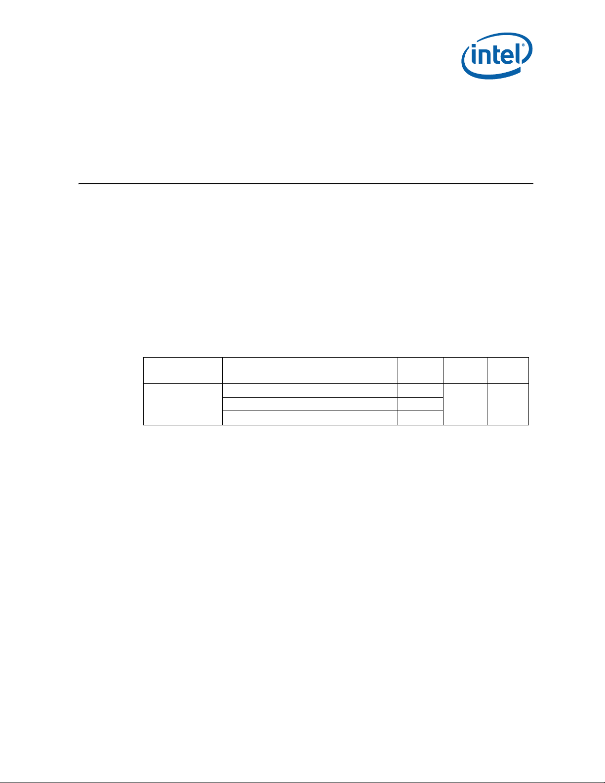
Table 2. Thermal Specifications for the Intel® Core™2 Duo processor
CPU Processor SKU# TDP (W)
Intel® Core™ 2 Duo
Mobile Processors
on 45-nm process
=
Standard Voltage (Core 2 Duo-6M, Celeron-2M) 35
Ultra Low Voltage (Core 2 Duo -2M, Celeron) 10
T
J-MAX
(°C)
105 0Low Voltage (Core 2 Duo -3M) 17
T
J-MIN
(°C)
June 2008 TDG
Order Number: 320028-001 10
Intel® Core™ 2 Duo Mobile Processors on 45-nm process for Embedded Applications
Page 11

Core™ 2 Duo Mobile Processors—Mechanical Specifications
4.0 Mechanical Specifications
4.1 Package Mechanical Requirements
4.1.1 Die Pressure/Load Upper Limit
From a die mechanical integrity standpoint, the maximum allowable normal die load is the lesser of
15 lbs or 100 psi. Considering the 15 lbs load limit and the nominal die area of 1.45 cm
this equates to a die pressure of 66.7 psi (below 100 psi specification). Considering the maximum
pressure specification, the die load at this pressure would be 22.4 lbs, exceeding the 15 lbs. load
limit. Thus, the heatsink clamping mechanism (spring loaded fasteners, spring clips, etc.) should not
exceed 15 lbs.
2
(0.22 in.2),
4.1.2 Die Pressure/Load Lower Limit
From a TIM performance standpoint, a minimum die pressure is required to ensure consistent and
minimal TIM thermal resistance. This lower value is a function of the TIM used. F or the phase-change
TIM specified for thermal solutions mentioned later, die pressure should not be lower than
approximately 138 kPa (20 psi). This will keep TIM resistance better than approximately
0.30 oC-cm2/W.
4.2 Package Keep Out Zones Requirements
The heatsink must not touch the package in the areas shown in Figure 2 and Figure 4. The heatsink
should include a means to prevent the heatsink from forming an electrical short with the capacitors
placed on the top side of the package. The reference thermal solutions include z-stops machined into
the base of the heatsink. The z-stops prevent the heatsink from inadvertently tilting when installed.
Other methods are suitable including using electrically insulated gasket material at the base of the
heatsink.
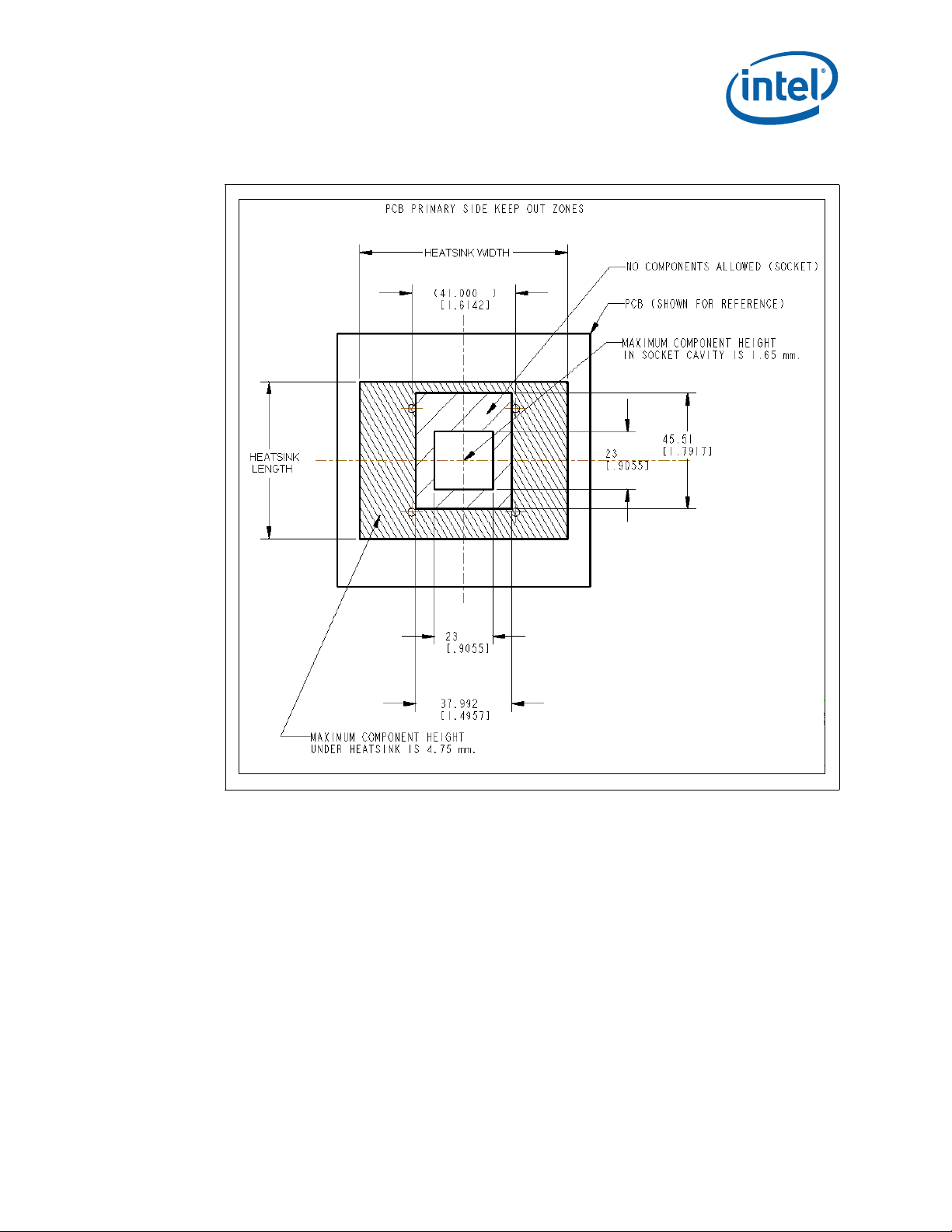
4.3 Board Level Keep Out Zone Requirements
A general description of the keep-out zones and mounting hole pattern for the reference thermal
solutions are shown in Figure 2 and Figure 3. Detailed drawings for the PCB keep out zones are in
Appendix B.
Components placed between the underside of the heatsink and motherboard cannot exceed 4.75 mm
in height when using heatsinks that extend beyond the socket envelope shown in Figure 2 for the
micro-FCPGA package.
Intel® Core™ 2 Duo Mobile Processors on 45-nm process-Thermal Design Guide
TDG June 2008
11 Order Number: 320028-001
Page 12
Mechanical Specifications—Core™ 2 Duo Mobile Processors
Figure 2. Primary Side Keep Out Zone Requirements— Micro-FCPGA
Notes:
1. Dimension in millimeters [inches].
June 2008 TDG
Order Number: 320028-001 12
Intel® Core™ 2 Duo Mobile Processors on 45-nm process for Embedded Applications
Page 13
Core™ 2 Duo Mobile Processors—Mechanical Specifications
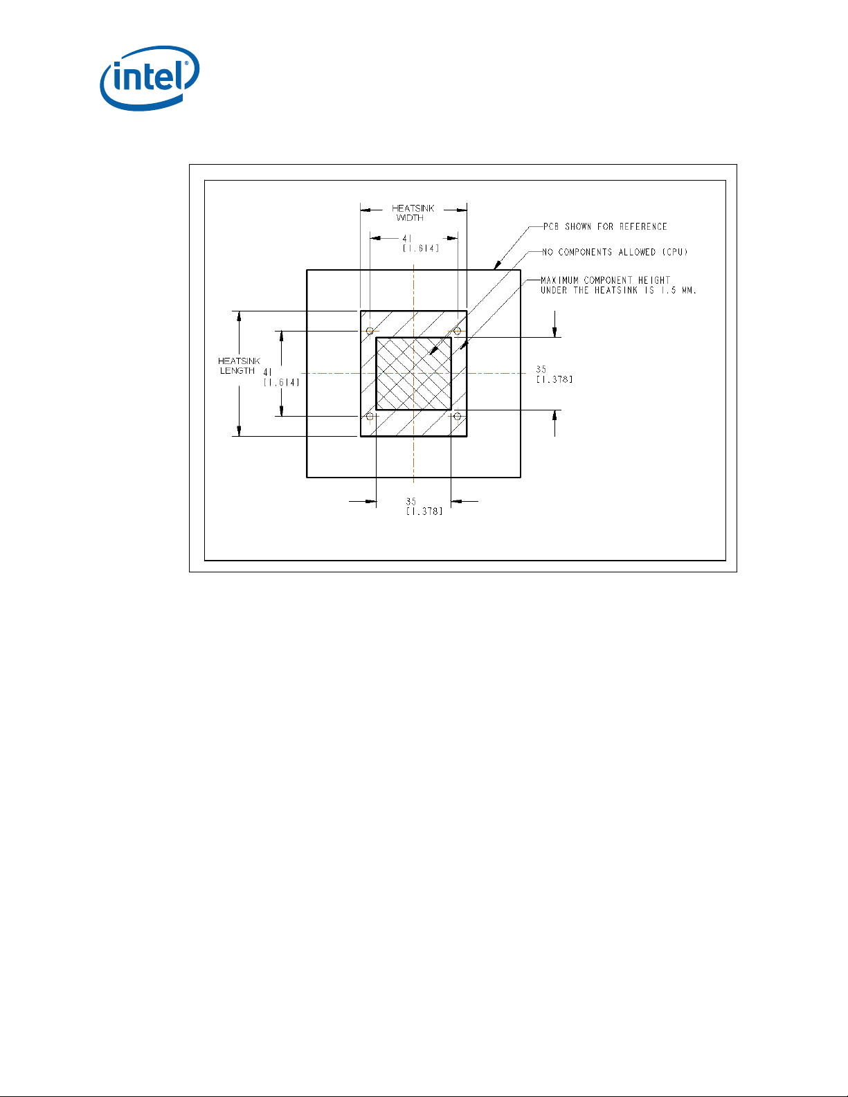
Figure 3. Primary Side Keep Out Zone Requirements— Micro-FCBGA
Notes:
1. Dimension in millimeters [inches].
Intel® Core™ 2 Duo Mobile Processors on 45-nm process-Thermal Design Guide
TDG June 2008
13 Order Number: 320028-001
Page 14

Mechanical Specifications—Core™ 2 Duo Mobile Processors
Figure 4. Secondary Side Keep Out Zone Requirements
Notes:
1. Dimension in millimeters [inches].
June 2008 TDG
Order Number: 320028-001 14
Intel® Core™ 2 Duo Mobile Processors on 45-nm process for Embedded Applications
Page 15

Core™ 2 Duo Mobile Processors—Thermal Solution Requirements
−
5.0 Thermal Solution Requirements
5.1 Thermal Solution Characterization
The thermal characterization parameter, Ψ (“psi”), is used to characterize thermal solution
performance, as well as compare thermal solutions in identical situations (i.e., heating source, local
ambient conditions, etc.). It is defined by the following equation:
Equation 1. Junction-to-Local Ambient Thermal Characterization Parameter (Ψ
TT
=Ψ
JA
Ψ
= Junction-to-local ambient thermal characterization parameter (°C/W)
JA
T
JUNCTION MAX
T
= Local ambient temperature near the device (°C) (see Section 7.0, “Thermal Metrology” for
A
measurement guidelines)
= Maximum allowed device temperature (°C)
AJ
TDP
JA
)
TDP = Thermal Design Power (W)
The thermal characterization parameter assumes that all package power dissipation is through the
thermal solution (heatsink), and is equal to TDP. A small percentage of the die power (< 5%) is
dissipated through the package/socket/motherboard stack to the environment, and should not be
considered to be a means of thermal control.
The junction-to-local ambient thermal characterization parameter, Ψ
includes the thermal interface material thermal characterization parameter, and of Ψ
local ambient thermal characterization parameter:
, is comprised of ΨJS, which
JA
, the sink-to-
SA
Equation 2. Junction-to-Local Ambient Thermal Characterization Parameter
Ψ
JA = ΨJS + ΨSA
Where:
= Thermal characterization parameter from junction-to-sink, this also includes thermal resistance
Ψ
JS
of the thermal interface material (Ψ
Ψ
= Thermal characterization parameter from sink-to-local ambient (°C/W)
SA
Ψ
is a measure of the thermal characterization parameter from the bottom of the heatsink to the
SA
local ambient air. Ψ
also strongly dependent on the air velocity through the fins of the heatsink. Figure 5 illustrates the
is dependent on the heatsink material, thermal conductivity , and geometry. It is
SA
) (°C/W).
TIM
combination of the different thermal characterization parameters.
Intel® Core™ 2 Duo Mobile Processors on 45-nm process-Thermal Design Guide
TDG June 2008
15 Order Number: 320028-001
Page 16

Thermal Solution Requirements—Core™ 2 Duo Mobile Processors
A
Ψ
Ψ
A
Ψ
Ψ
−=−
Figure 5. Processor Thermal Characterization Parameter Relationships
Device
HEATSINK
TIM
T
T
SA
SA
T
T
S
S
T
J
TIM
Ψ
Ψ
JA
5.1.1 Calculating the Required Thermal Performance for the Intel® Core™2 Duo processor
Overall thermal performance, Ψ
• Define a target component temperature T
• Define a target local ambient temperature, T
The following provides an illustration of how to determine the appropriate performance targets.
is then defined using the thermal characterization parameter:
JA,
JUNCTION
and corresponding TDP.
.
A
Assume:
•TDP = 35 W and T
• Local processor ambient temperature, T
Using Equation 1, the maximum allowable resistance, junction-to-ambient, is calculated as:
Equation 3. Maximum Allowable Resistance
To determine the required heatsink performance, a heatsink solution provider would need to
determine Ψ
solution were designed to work with a TIM material performing at Ψ
Equation 2, the performance of the heatsink required is:
Equation 4. Required Performance of the Heatsink
performance for the selected TIM and mechanical load configuration. If the heatsink
CA
JUNCTION
= 105 °C
=Ψ
JA
= 40 °C.
A
TT
AJ
TDP
JSJASA
35
40105
=
o
WC
/857.1
≤ 0.50 °C/W, solving from
TIM
o
WC
/36.150.086.1 =−=Ψ−Ψ=Ψ
June 2008 TDG
Order Number: 320028-001 16
Intel® Core™ 2 Duo Mobile Processors on 45-nm process for Embedded Applications
Page 17

Core™ 2 Duo Mobile Processors—Thermal Solution Requirements
It is evident from the above calculations that a reduction in the local ambient temperature can have a
significant effect on the junction-to-ambient thermal resistance requirement. This effect can
contribute to a more reasonable thermal solution including reduced cost, heatsink size, heatsink
weight, or a lower system airflow rate.
Table 3 summarizes the thermal budget required to adequately cool the Intel® Core™ 2 Duo Mobile
Processors on 45-nm process. Since the data is based on air data at sea level, a correction factor
would be required to estimate the thermal performance at other altitudes.
Table 3. Required Heatsink Thermal Performance (Ψ
CPU Processor SKU
Intel® Core™ 2 Duo
Mobile Processors on 45nm process
Notes:
1. T
is defined as the local (internal) ambient temperature measured approximately 1 inch upstream
A
from the device.
Standard Voltage
(Core 2 Duo-6M,
Celeron-2M)
Low Voltage
(Core 2 Duo -3M)
Ultra Low Voltage
(Core 2 Duo -2M,
Celeron)
TDP
(W)
35 1.86 1.42
17 3.82 2.94
10 6.5 5.0
JA
Ψ
at T
)
JA
(ºC/W)
= 40 ºC
A
Ψ
at T
(ºC/W)
JA
= 55 ºC
A
Intel® Core™ 2 Duo Mobile Processors on 45-nm process-Thermal Design Guide
TDG June 2008
17 Order Number: 320028-001
Page 18
Reference Thermal Solutions—Core™ 2 Duo Mobile Processors
6.0 Reference Thermal Solutions
Intel has developed reference thermal solutions designed to meet the cooling needs of embedded
form factor applications. This chapter describes the overall requirements for the reference thermal
solution including critical-to-function dimensions, operating environment, and verification criteria.
This document details solutions that are compatible with the AdvancedTCA* and Server System
Infrastructure (1U and larger) form factors.
The data in this section is based on wind tunnel testing of the reference thermal solutions. The
heatsinks were tested as an assembly with a thermal test vehicle (TTV), TIM, socket and test board.
The test assembly is placed in a rectangular duct with no upstream obstructions. Air flow is measured
by means of a calibrated nozzle downstream of the unit under test. The Ψ values shown in the charts
to follow represent the mean resistance values plus the one-sided, 99 percent confidence interval.
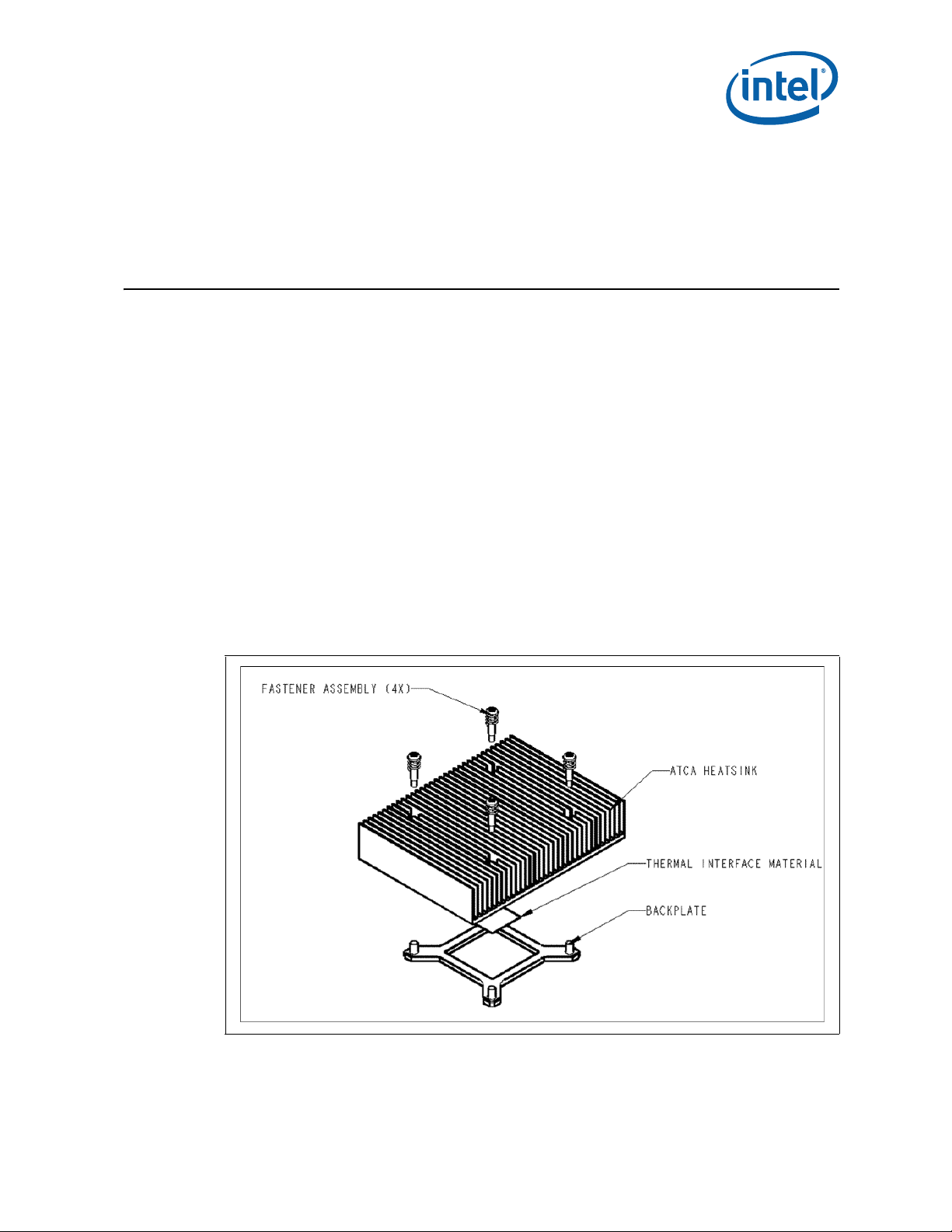
6.1 ATCA Reference Thermal Solution
The AdvancedTCA reference thermal solution is shown in Figure 6. The maximum component height
for this form factor is 21.33 mm, so the maximum heatsink height is constrained to 16.27 mm. The
heatsink uses the fastener assembly to mount to the PCB as described in Section 6.6, “Heatsink
Fastener Assembly” . Detailed drawings of this heatsink are provided in Appendix B, “Mechanical
Drawings”.
Figure 6. AdvancedTCA* Reference Heatsink Assembly
June 2008 TDG
Order Number: 320028-001 18
Intel® Core™ 2 Duo Mobile Processors on 45-nm process for Embedded Applications
Page 19

Core™ 2 Duo Mobile Processors—Reference Thermal Solutions
6.2 Keep Out Zone Requirements
The keep out zone requirements on the PCB to use this heatsink are detailed in Appendix B,
“Mechanical Drawings”. Because it extends beyond the footprint of the device, it is critical for the
board designer to allocate space on the board for the heatsink.
6.3 Thermal Performance
The AdvancedTCA reference heatsink is an all copper (C1100) design. The performance of this
heatsink has been tested at flow rates from 10 CFM to 30 CFM. The heatsink is expected to meet the
thermal performance needed when the air flow rate is at least 10 CFM at 40 °C. For an external
ambient of 55°C (ψ
15 CFM.
Figure 7. AdvancedTCA* Heatsink Thermal Performance vs. Volumetric Airflow Rate
= 1.32 °C/W), this heatsink is expected to be suitable for air flow rates around
ja
6.4 1U+ Reference Heatsink
The 1U reference thermal solution is shown in Figure 8. The maximum heatsink height is constrained
to 27 mm. The heatsink uses the fastener assembly (refer to Section 6.6) to mount to the PCB.
Detailed drawings of this heatsink are provided in Appendix B, “Mechanical Drawings”.
Intel® Core™ 2 Duo Mobile Processors on 45-nm process-Thermal Design Guide
TDG June 2008
19 Order Number: 320028-001
Page 20

Reference Thermal Solutions—Core™ 2 Duo Mobile Processors
Figure 8. 1U Reference Heatsink Assembly
6.4.1 Keep Out Zone Requirements
The keep out zone requirements on the PCB to use this heatsink are detailed in Appendix B,
“Mechanical Drawings”. Because it extends beyond the footprint of the device, it is critical for board
designers to allocate space for the heatsink.
6.4.2 Thermal Performance
The 1U reference heatsink employs a thick copper (C1100) base with aluminum (Al 1050) stamped
fins, soldered to the base. The heatsink has been tested at flow rates from 10 CFM to 25 CFM. For a
40 °C external ambient and 35 W TDP, the heatsink is expected to meet the thermal performance
needed when the air flow rate is greater than 10 CFM. If the external ambient is 55 °C, this heatsink
will be suitable if the air flow rate is approximately 12 CFM or greater.
June 2008 TDG
Order Number: 320028-001 20
Intel® Core™ 2 Duo Mobile Processors on 45-nm process for Embedded Applications
Page 21

Core™ 2 Duo Mobile Processors—Reference Thermal Solutions
Figure 9. 1U Heatsink Thermal Performance vs. Volumetric Airflow Rate
1U+ Reference Heatsink Perfor mance
1.6
1.4
1.2
1
0.8
PSI (C/W)
0.6
0.4
0.2
0
0 5 10 15 20 25 30
Psi_ja
Psi_sa
Volumetric Air Flow Rate (CFM)
6.5 Compact PCI Reference Heatsink
The cPCI reference thermal solution is shown in Figure 10. The maximum heatsink height is
constrained to 8.7 mm. The heatsink uses the fastener assembly (refer to Section 6.6) to mount to
the PCB. Detailed drawings of this heatsink are provided in Appendix B, “Mechanical Drawings”.
Figure 10. CompactPCI Reference Heatsink Assembly
Intel® Core™ 2 Duo Mobile Processors on 45-nm process-Thermal Design Guide
TDG June 2008
21 Order Number: 320028-001
Page 22

Reference Thermal Solutions—Core™ 2 Duo Mobile Processors
6.5.1 Keep Out Zone Requirements
The keep out zone requirements on the PCB to use this heatsink are detailed in Appendix B,
“Mechanical Drawings.” Because it extends beyond the footprint of the device, it is critical for board
designers to allocate space for the heatsink.
6.5.2 Thermal Performance
The cPCI reference heatsink is an all copper (C1100) design, intended for applications where vertical
space is limited. The heatsink has been tested at flow rates from 4 CFM to 24 CFM. For a 40 °C
external ambient and 17W TDP, the heatsink is expected to meet the thermal performance needed
when the air flow rate is at least 4 CFM.
Figure 11. cPCI Reference Heatsink Thermal Performance vs. Volumetric Flow Rate
6.6 Heatsink Fastener Assembly
The reference solutions use a screw, spring, and back plate assembly to attach the heatsink to the
PCB. The fastener assembly used on the reference heatsink must apply the load conditions described
in Section 4.1, “Package Mechanical Requirements” . The fastener assembly must comply with all of
the keep out zone requirements described in this document, and should not degrade the thermal
performance of the reference heatsinks. Finally the fastener assembly should be designed to meet the
reliability guidelines described in Section 8.0, “Reliability Guidelines” .
6.7 Thermal Interface Material (TIM)
The thermal interface material provides improved conductivity between the die and heatsink. It is
important to understand and consider the impact of the interface between the die and heatsink base
to the overall thermal solution. Specifically, the bond line thickness, interface material area, and
interface material thermal conductivity must be selected to optimize the thermal solution.
It is important to minimize the thickness of the thermal interface material (TIM), commonly referred
to as the bond line thickness. A large gap between the heatsink base and the die yields a greater
thermal resistance. The thickness of the gap is determined by the flatness of both the heatsink base
and the die, plus the thickness of the thermal interface material, and the clamping force applied by
the heatsink attachment method. To ensure proper and consistent thermal performance, the TIM and
application process must be properly designed.
June 2008 TDG
Order Number: 320028-001 22
Intel® Core™ 2 Duo Mobile Processors on 45-nm process for Embedded Applications
Page 23

Core™ 2 Duo Mobile Processors—Reference Thermal Solutions
Thermal interface materials have thermal impedance (resistance) that will increase as the material
degrades over time. It is important for thermal solution designers to take this increase in impedance
into consideration when designing a thermal solution. It is recommended that system integrators
work with TIM suppliers to determine the performance of the desired thermal interface material. If
system integrators wish to maintain maximum thermal solution performance, the TIM could be
replaced during standard maintenance cycles.
The reference thermal solution uses Shin Etsu* G751. Alternative materials can be used at the user’s
discretion. Regardless, the entire heatsink assembly , including the heatsink, and TIM (including attach
method), must be validated together for specific applications.
6.8 Heatsink Orientation
All of the heatsinks were designed to maximize the available space within the volumetric keep out
zone and their respective form factor limitations. These heatsinks must be oriented in a specific
direction relative to the processor keep out zone and airflow. In order to use these designs, the
processor must be placed on the PCB in an orientation so the heatsink fins will be parallel to the
airflow. Figure 12 illustrates this orientation.
Figure 12. Heatsink Orientation Relative to Airflow Direction
Intel® Core™ 2 Duo Mobile Processors on 45-nm process-Thermal Design Guide
TDG June 2008
23 Order Number: 320028-001
Page 24

Thermal Metrology—Core™ 2 Duo Mobile Processors
7.0 Thermal Metrology
The system designer must make temperature measurements to accurately determine the
performance of the thermal solution. Validation of the processor’s thermal solution should be done
using a thermal test vehicle (TTV). The T TV allows for an accurate junction temperature measurement
as well as input power control. For more information, contact your Intel field sales representative.
In addition, the processor’s heatsink should be verified in a system environment. Intel has established
guidelines for techniques to measure the component temperature. Section 7.1, “Die Temperature
Measurements” provides guidelines on how to accurately measure the component temperature.
Section 7.2, “Power Simulation Software” contains information on running an application program
that will emulate anticipated maximum thermal design power.
7.1 Die Temperature Measurements
The component T
noted in Section 3.2, “Maximum Allowed Component Temperature” . The best way to measure die
temperature is to use the Digital Thermal Sensor as described in the processor’s datasheet. Refer to
the processor datasheet for more information on the DTS.
The legacy on-board thermal diode is not recommended for performing heatsink validation. The
thermal diode is suitable for long term trending data, but is not a reliable indicator of the processor’s
temperature.
JUNCTION
must be maintained at or below the maximum temperature specification as
7.2 Power Simulation Software
The power simulation software is a utility designed to dissipate the thermal design power on a
processor. To assess the thermal performance of the processor thermal solution under “worst-case
realistic application” conditions, Intel is developing a software utility that operates the processor at
near worst-case power dissipation.
The power simulation software should only be used to test customer thermal solutions at or near the
thermal design power. For power supply current, please refer to each component’s datasheet for the
I
(Max Power Supply Current) specification. For information on how to obtain the maximum power
CC
program, contact your Intel field sales representative.
7.3 Additional Thermal Features
The Intel Core 2 Duo processor supports other thermal features including the Intel® Thermal Monitor,
PROCHOT#, FORCEPR#, and THERMTRIP# signal pins. Details for using these features are contained
in the processor datasheet.
7.4 Local Ambient Temperature Measurement Guidelines
The local ambient temperature (TLA) is the temperature of the ambient air surrounding the processor.
For a passive heatsink, T
heatsink, it is the temperature of inlet air to the active cooling fan.
June 2008 TDG
Order Number: 320028-001 24
is defined as the heatsink approach air temperature; for an actively cooled
A
Intel® Core™ 2 Duo Mobile Processors on 45-nm process for Embedded Applications
Page 25

Core™ 2 Duo Mobile Processors—Thermal Metrology
It is worthwhile to determine the local ambient temperature in the chassis around the processor to
understand the effect it may have on the case temperature. T
temperature measurements at multiple locations in the heatsink inlet airflow. This method helps
is best measured by averaging
LA
reduce error and eliminate minor spatial variations in temperature. The following guidelines are
meant to enable accurate determination of the localized air temperature around the processor during
system thermal testing.
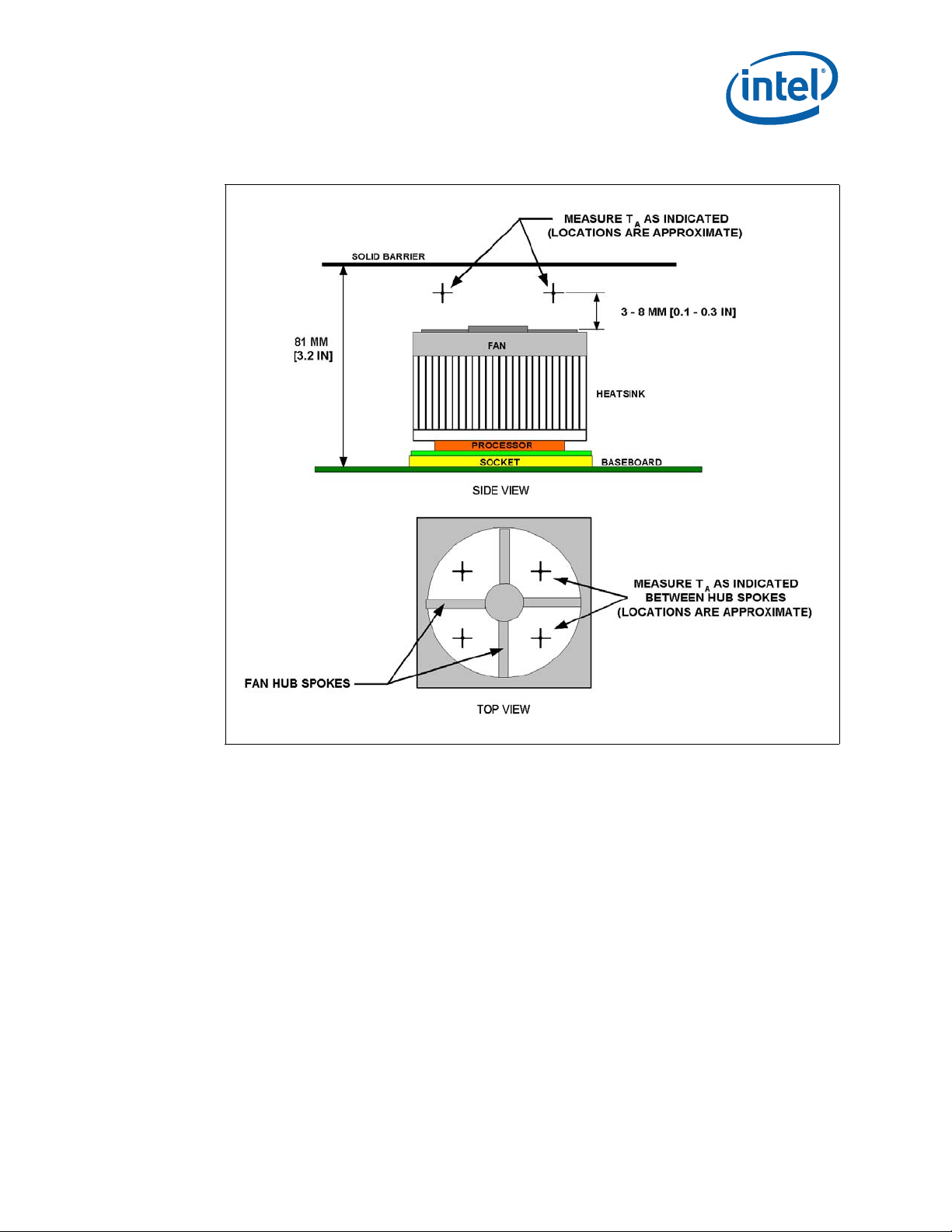
7.4.1 Active Heatsink Measurements
• It is important to avoid taking measurements in the dead flow zone that usually develops above
the fan hub and hub spokes. Measurements should be taken at four different locations uniformly
placed at the center of the annulus formed by the fan hub and the fan housing to evaluate the
uniformity of the air temperature at the fan inlet. The thermocouples should be placed
approximately 3 mm to 8 mm [0.1 to 0.3 in.] above the fan hub vertically and halfway between
the fan hub and the fan housing horizontally as shown in Figure 13 (avoiding the hub spokes).
• Using an open bench to characterize an active heatsink can be useful, and usually ensures more
uniform temperatures at the fan inlet. However, additional tests that include a solid barrier above
the test motherboard surface can help evaluate the potential impact of the chassis. This barrier is
typically clear Plexiglas*, extending at least 100 mm [4 in.] in all directions beyond the edge of
the thermal solution. Typical distance from the motherboard to the barrier is 81 mm [3.2 in.]. If a
barrier is used, the thermocouple can be taped directly to the barrier with clear tape at the
horizontal location as previously described, halfway between the fan hub and the fan housing.
• For even more realistic airflow, the motherboard should be populated with significant elements
like memory cards, graphic card, and chipset heatsink. If a variable speed fan is used, it may be
useful to add a thermocouple taped to the barrier above the location of the temperature sensor
used by the fan to check its speed setting against air temperature. When measuring T
chassis with a live motherboard, add-in cards, and other system components, it is likely that the
T
measurements will reveal a highly non-uniform temperature distribution across the inlet fan
LA
section.
LA
in a
Note: Testing an active heatsink with a variable speed fan can be done in a thermal chamber
to capture the worst-case thermal environment scenarios. Otherwise, when doing a
bench top test at room temperature, the fan regulation prevents the heatsink from
operating at its maximum capability. To characterize the heatsink capability in the
worst-case environment in these conditions, it is then necessary to disable the fan
regulation and power the fan directly, based on guidance from the fan supplier.
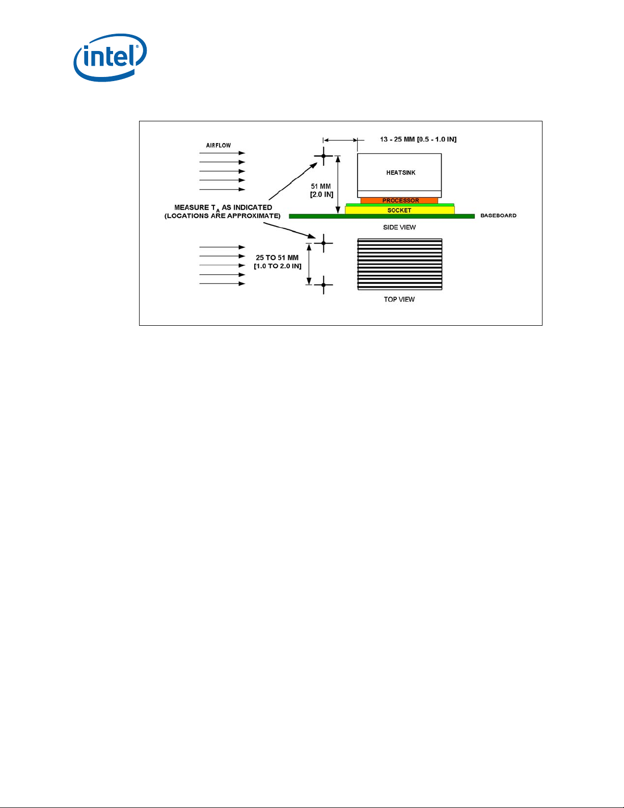
7.4.2 Passive Heatsink Measurements
• Thermocouples should be placed approximately 13 mm to 25 mm [0.5 to 1.0 in.] away from
processor and heatsink as shown in Figure 14.
• The thermocouples should be placed approximately 51 mm [2.0 in.] above the baseboard. This
placement guideline is meant to minimize the effect of localized hot spots from baseboard
components. The height above the board may vary depending on the height of the thermal
solution and form factor.
Intel® Core™ 2 Duo Mobile Processors on 45-nm process-Thermal Design Guide
TDG June 2008
25 Order Number: 320028-001
Page 26
Thermal Metrology—Core™ 2 Duo Mobile Processors
Figure 13. Measuring T
with an Active Heatsink
LA
Note: Drawing not to scale.
June 2008 TDG
Order Number: 320028-001 26
Intel® Core™ 2 Duo Mobile Processors on 45-nm process for Embedded Applications
Page 27
Core™ 2 Duo Mobile Processors—Thermal Metrology
Figure 14. Measuring T
with a Passive Heatsink
LA
Note: Drawing not to scale.
Intel® Core™ 2 Duo Mobile Processors on 45-nm process-Thermal Design Guide
TDG June 2008
27 Order Number: 320028-001
Page 28

Reliability Guidelines—Core™ 2 Duo Mobile Processors
8.0 Reliability Guidelines
Each motherboard, heatsink, and attach combination may vary the mechanical loading of the
component. The user should carefully evaluate the reliability of the completed assembly prior to use
in high volume. Some general recommendations are shown in Table 4.
Table 4. Reliability Requirements
1
Test
Mechanical Shock 50 g, board level, 11 msec, 3 shocks/axis
Random Vibration 7.3 g, board level, 45 min/axis, 50 Hz to 2000 Hz
Temperature Life
Thermal Cycling -5 °C to +70 °C, 500 cycles Visual Check
Humidity 85% relative humidity, 55 °C, 1000 hours Visual Check
Notes:
1. The above tests should be performed on a sample size of at least 12 assemblies from three lots of
2. Additional pass/fail criteria may be added at the discretion of the user.
material.
85 °C, 2000 hours total, checkpoints at 168, 500,
1000, and 2000 hours
Requirement Pass/Fail Criteria
Visual Check and Electrical
Functional Test
Visual Check and Electrical
Functional Test
Visual Check
2
June 2008 TDG
Order Number: 320028-001 28
Intel® Core™ 2 Duo Mobile Processors on 45-nm process for Embedded Applications
Page 29
Core™ 2 Duo Mobile Processors—Thermal Solution Component Suppliers
Appendix A Thermal Solution Component Suppliers
These vendors and devices are listed by Intel as a convenience to Intel’ s general customer base. Intel
does not make any representations or warranties whatsoever regarding quality, reliability,
functionality, or compatibility of these devices. This list and/or these devices may be subject to
change without notice.
Note: The enabled components may not be currently available from all suppliers. Contact the
supplier directly to verify availability.
Table 5. Reference Heatsink
Part Part Number Contact Information
AdvancedTCA* passive heatsink assembly ECC-00177-01-GP
1U+ passive heatsink assembly ECC-00179-01-GP
cPCI passive heatsink assembly ECC-00178-01-GP
Thermal Interface Material PCM45F
Cooler Master*
Wendy Lin
wendy@coolermaster.com
(510)770-8566 ext 211
Honeywell*
Paula Knoll
paula.knoll@honeywell.com
(858) 279-2956
Intel® Core™ 2 Duo Mobile Processors on 45-nm process-Thermal Design Guide
TDG June 2008
29 Order Number: 320028-001
Page 30
Mechanical Drawings—Core™ 2 Duo Mobile Processors
Appendix B Mechanical Drawings
Table 6 lists the mechanical drawings included in this appendix.
Table 6. Mechanical Drawings
Description Figure
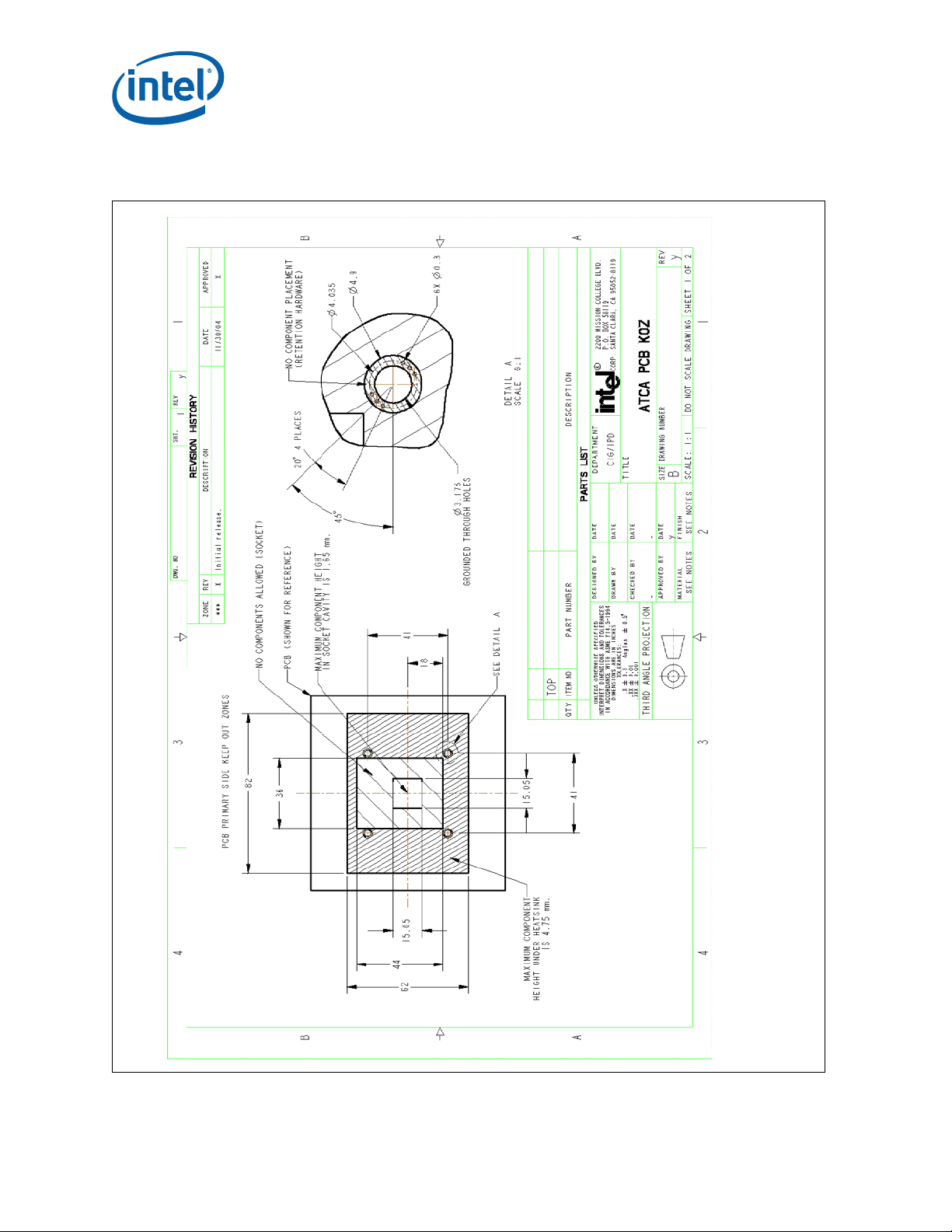
AdvancedTCA* Refere nce Heatsink PCB Keep Out Zone Requirements (Sheet 1 of 2) Figure 15
AdvancedTCA* Re ference Heatsink PCB K eep Out Z one Re quirements (Sheet 2 of 2) Figure 16
AdvancedTCA* Reference Heatsink Assembly Figure 17
AdvancedTCA* Reference Heatsink Figure 18
CompactPCI* Reference Heatsink PCB Keep Out Zone Requirements (Sheet 1 of 2) Figure 19
CompactPCI* Reference Heatsink PCB Keep Out Zone Requirements (Sheet 2 of 2) Figure 20
CompactPCI* Reference Heatsink Assembly Figure 21
CompactPCI* Reference Heatsink Figure 22
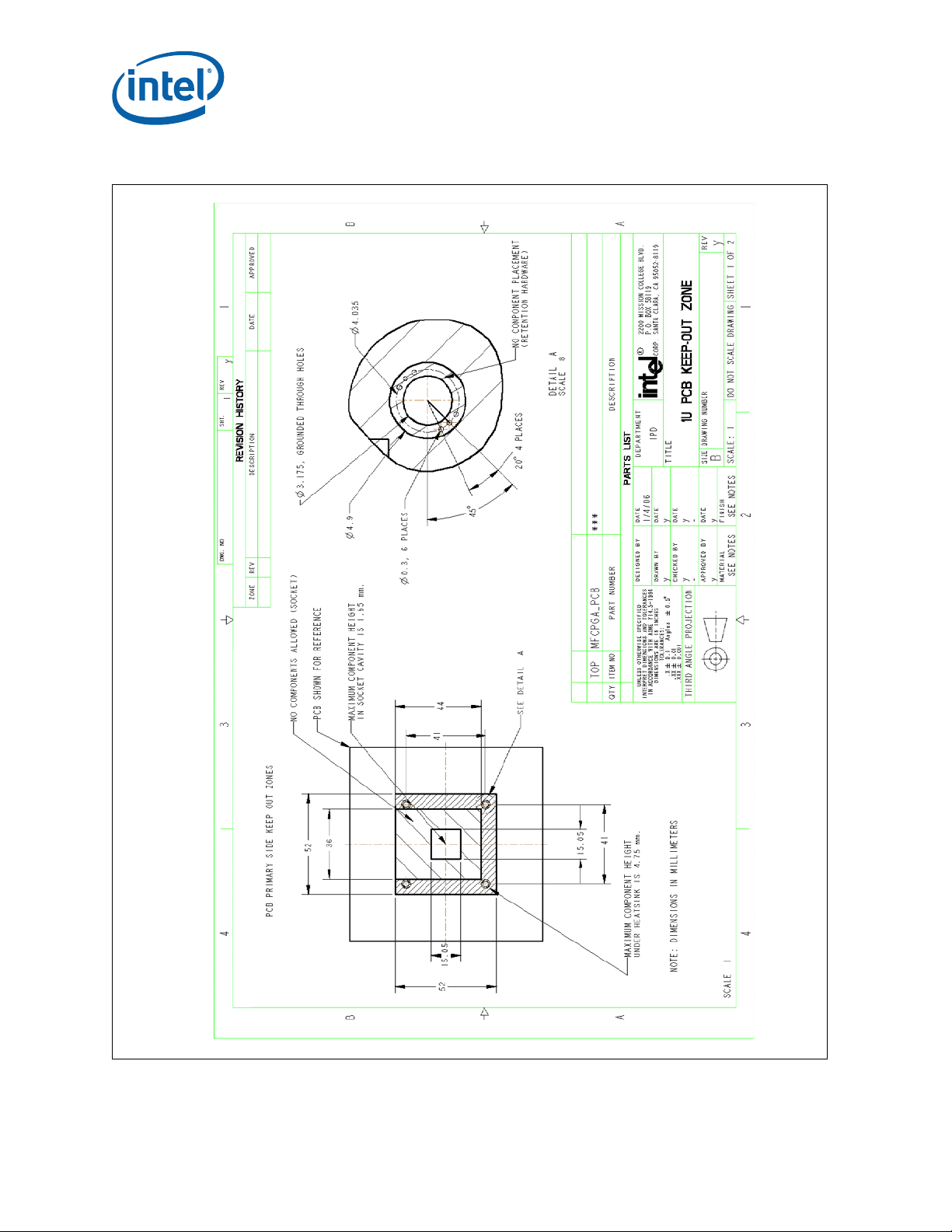
1U Reference Heatsink PCB Keep Out Requirements (Sheet 1 of 2) Figure 23
1U Reference Heatsink PCB Keep Out Requirements (Sheet 2 of 2) Figure 24
1U Reference Heatsink Assembly Figure 25
1U Reference Heatsink Figure 26
June 2008 TDG
Order Number: 320028-001 30
Intel® Core™ 2 Duo Mobile Processors on 45-nm process for Embedded Applications
Page 31
Core™ 2 Duo Mobile Processors—Mechanical Drawings
Figure 15. AdvancedTCA* Reference Heatsink PCB Keep Out Zone Requirements (Sheet 1
of 2)
Intel® Core™ 2 Duo Mobile Processors on 45-nm process-Thermal Design Guide
TDG June 2008
31 Order Number: 320028-001
Page 32

Mechanical Drawings—Core™ 2 Duo Mobile Processors
Figure 16. AdvancedTCA* Reference Heatsink PCB Keep Out Zone Requirements (Sheet 2
of 2)
June 2008 TDG
Order Number: 320028-001 32
Intel® Core™ 2 Duo Mobile Processors on 45-nm process for Embedded Applications
Page 33

Core™ 2 Duo Mobile Processors—Mechanical Drawings
Figure 17. AdvancedTCA* Reference Heatsink Assembly
Intel® Core™ 2 Duo Mobile Processors on 45-nm process-Thermal Design Guide
TDG June 2008
33 Order Number: 320028-001
Page 34

Mechanical Drawings—Core™ 2 Duo Mobile Processors
Figure 18. AdvancedTCA* Reference Heatsink
June 2008 TDG
Order Number: 320028-001 34
Intel® Core™ 2 Duo Mobile Processors on 45-nm process for Embedded Applications
Page 35

Core™ 2 Duo Mobile Processors—Mechanical Drawings
Figure 19. CompactPCI* Reference Heatsink PCB Keep Out Zone Requirements (Sheet 1
of 2)
Intel® Core™ 2 Duo Mobile Processors on 45-nm process-Thermal Design Guide
TDG June 2008
35 Order Number: 320028-001
Page 36

Mechanical Drawings—Core™ 2 Duo Mobile Processors
Figure 20. CompactPCI* Reference Heatsink PCB Keep Out Zone Requirements (Sheet 2
of 2)
June 2008 TDG
Order Number: 320028-001 36
Intel® Core™ 2 Duo Mobile Processors on 45-nm process for Embedded Applications
Page 37

Core™ 2 Duo Mobile Processors—Mechanical Drawings
Figure 21. CompactPCI* Reference Heatsink Assembly
Intel® Core™ 2 Duo Mobile Processors on 45-nm process-Thermal Design Guide
TDG June 2008
37 Order Number: 320028-001
Page 38

Mechanical Drawings—Core™ 2 Duo Mobile Processors
Figure 22. CompactPCI* Reference Heatsink
June 2008 TDG
Order Number: 320028-001 38
Intel® Core™ 2 Duo Mobile Processors on 45-nm process for Embedded Applications
Page 39
Core™ 2 Duo Mobile Processors—Mechanical Drawings
Figure 23. 1U Reference Heatsink PCB Keep Out Requirements (She et 1 of 2)
Intel® Core™ 2 Duo Mobile Processors on 45-nm process-Thermal Design Guide
TDG June 2008
39 Order Number: 320028-001
Page 40

Mechanical Drawings—Core™ 2 Duo Mobile Processors
Figure 24. 1U Reference Heatsink PCB Keep Out Requirements (Sheet 2 of 2)
June 2008 TDG
Order Number: 320028-001 40
Intel® Core™ 2 Duo Mobile Processors on 45-nm process for Embedded Applications
Page 41
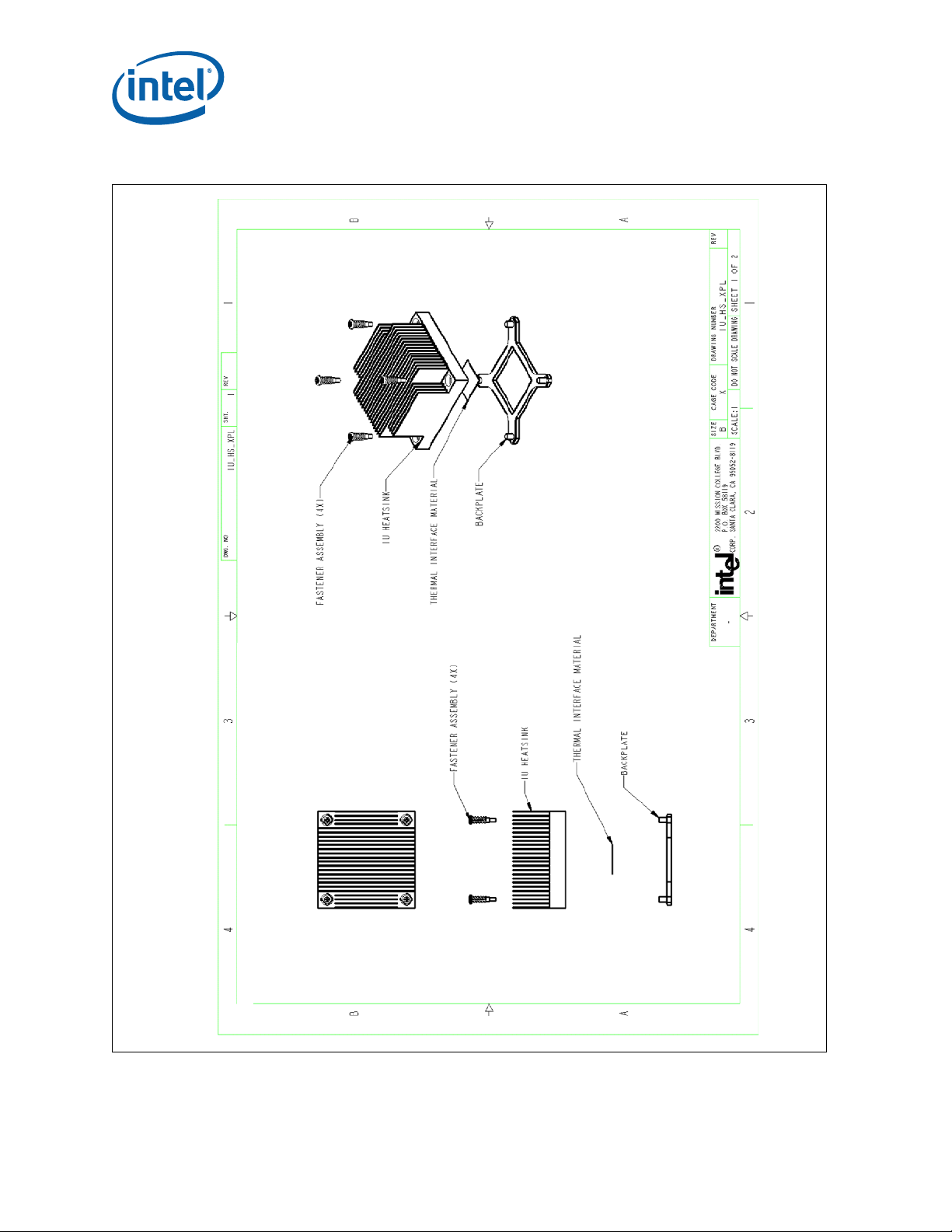
Figure 25. 1U Reference Heatsink Assembly
Core™ 2 Duo Mobile Processors—Mechanical Drawings
Intel® Core™ 2 Duo Mobile Processors on 45-nm process-Thermal Design Guide
TDG June 2008
41 Order Number: 320028-001
Page 42
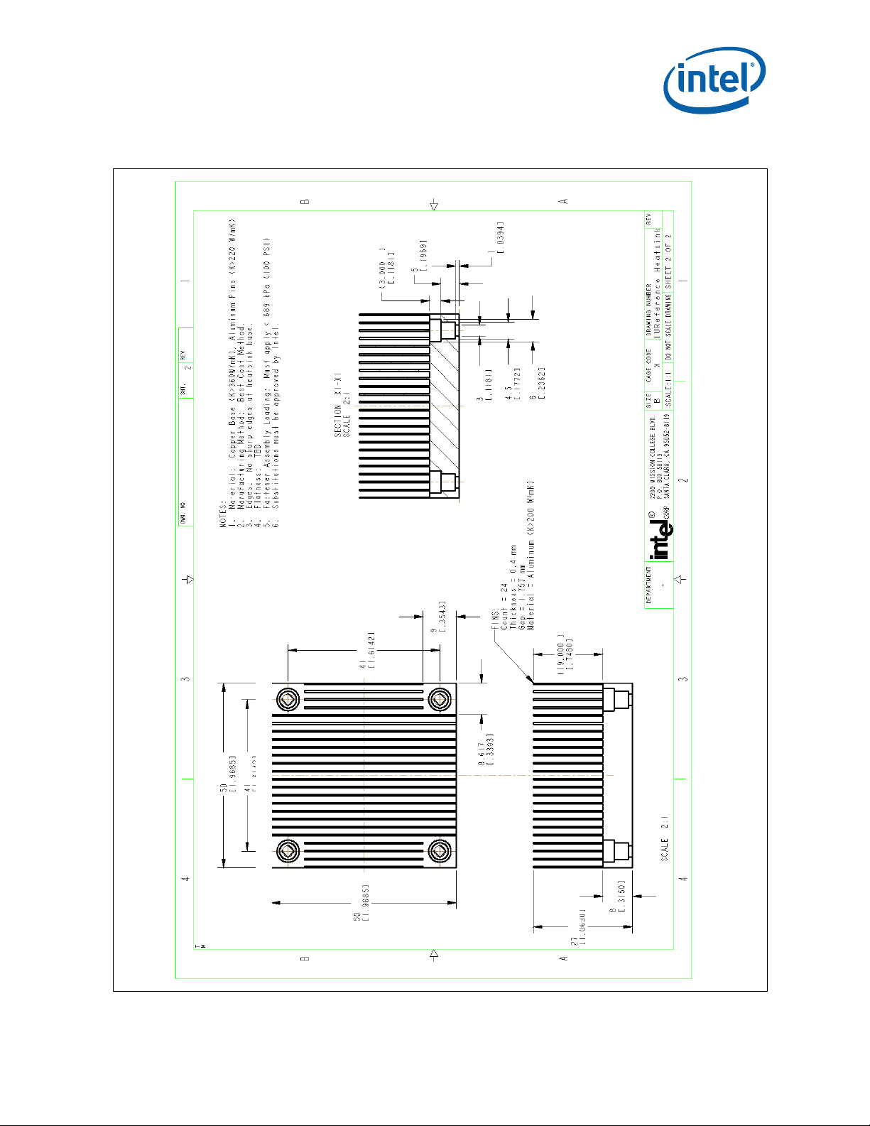
Mechanical Drawings—Core™ 2 Duo Mobile Processors
Figure 26. 1U Reference Heatsink
June 2008 TDG
Order Number: 320028-001 42
Intel® Core™ 2 Duo Mobile Processors on 45-nm process for Embedded Applications
 Loading...