

Page 1

> Before Start > Part Names > Install > Initial Setup > Playback > Advanced Manual
Troubleshooting | Supplementary Information, etc.
AV R e c e i v e r
DRX-3.1
Before Start ............................................................................2
What's in the box......................................................................2
Part Names .............................................................................3
Part Names ..............................................................................3
Install ......................................................................................7
Installation procedure ...............................................................7
Step1: Speaker Layout .............................................................8
Step2: Connect the Speakers.................................................14
Basic Manual
Step3: Connect the TV & AV Components.............................16
Initial Setup ..........................................................................22
Initial Setup with Auto Start-up Wizard ...................................22
Playback ...............................................................................24
AV Component Playback........................................................24
BLUETOOTH
Network Functions..................................................................25
USB Storage Device...............................................................26
Listening to the AM/FM Radio................................................27
Multi-zone...............................................................................29
Listening Mode.......................................................................30
®
Playback........................................................24
The Basic Manual includes information needed when starting up and
also instructions for frequently used operations. The Advanced Manual
has more detailed information and advanced settings.
Page 2

Before Start
> Before Start > Part Names > Install > Initial Setup > Playback > Advanced Manual
Troubleshooting | Supplementary Information, etc.
1
32
54
6
What's in the box
1. Main unit (1)
2. Remote controller (RC-912R) (1), Batteries (AAA/R03)
(2)
3. Speaker setup microphone (1)
0 Used during Initial Setup.
4. Indoor FM antenna (1)
5. AM loop antenna (1)
6. Power cord (1)
0 Quick Start Guide (1)
0 Basic Manual (This manual)
0 Connect speakers with 4 Ω to 16 Ω impedance.
0 The power cord must be connected only after all other
cable connections are completed.
0 We will not accept responsibility for damage arising from
the connection of equipment manufactured by other
companies.
0 Functionality may be introduced by firmware updates
and service providers may cease services, meaning that
some network services and content may become
unavailable in the future. Furthermore, available services
may vary depending on your area of residence.
0 Details on the firmware update will be posted on our
website, etc.
0 Specifications and appearance are subject to change
without prior notice.
2
Page 3

Part Names
> Before Start > Part Names >Install >Initial Setup >Playback > Advanced Manual
Troubleshooting | Supplementary Information, etc.
En
Part Names
(*)You can find details in the Advanced Manual.
Front Panel
1. Í On/Standby button
2. Hybrid Standby indicator: Lights if the unit enters standby mode when the features are
enabled that continue to work when this unit is in standby, such as HDMI Standby
Through and Network Standby.
3. You can adjust the sound quality of the front speakers. Press Tone to select the desired
setting from "Bass" and "Treble", and adjust with + and –.
4. Remote control sensor: Receives signals from the remote controller.
0 The signal range of the remote controller is within about 16´/5 m, at an angle of 20° on
the perpendicular axis and 30° to either side.
5. Listening Mode button: Press the Listening Mode button (above) repeatedly to select a
category from "Movie/TV", "Music", "Game", then turn the Listening Mode dial (below) to
change the mode (P30). (*)
6. Display (P4)
7. Dimmer button: You can adjust the brightness of the display in three steps. It cannot be
turned off completely.
8. Memory button: Used to register AM/FM radio stations (P28).
9. Tuning Mode button: Switches the tuning mode (P27).
10.
Info button: Switches the information on the display (P30).
11.
Setup button: You can show advanced setting items on the TV and display to provide you
with an even better experience. (*)
12.
Cursor buttons ( / / / ) and Enter button: Select the item with the cursors and
press Enter to confirm. Use them to tune to stations when using Tuner.
13.
Return button: Returns the display to the previous state.
14.
Master Volume
3
Page 4

> Before Start > Part Names >Install >Initial Setup >Playback > Advanced Manual
Troubleshooting | Supplementary Information, etc.
(*)You can find details in the Advanced Manual.
15.
Zone 2 button: Controls the multi-zone function (P29).
Off button: Switches the multi-zone function off (P29).
16.
Zone 2 Level 4/3 buttons: Adjust the volume of the
multi-zone feature (P29).
17.
Phones jack: Headphones with a standard plug
(Ø1/4"/6.3 mm) are connected.
18.
AUX Input HDMI jack: Connect to a video camera, etc.,
using a HDMI cable.
19.
Input selector buttons: Switches the input to be played.
20.
AUX Input Video/Audio jacks: Input the video and audio
signals from an external player with an analog audio/
video cable.
21.
Setup Mic jack: The supplied speaker setup
microphone is connected.
Display
1. Speaker/Channel display: Displays the output channel that
corresponds to the selected listening mode.
2. Lights in the following conditions.
Ë: When headphones are connected.
Z2: When ZONE 2 is on.
: When connected by BLUETOOTH.
: When connected by Wi-Fi.
NET: When "NET" is selected with the input selector and the unit is
connected to the network. It will flash if the connection to the network is
not correct.
USB: When "NET" is selected with the input selector and the unit is
connected by USB and the USB device is selected. Flashes if the USB
is not properly connected.
HDMI: When HDMI signals are input and the HDMI input is selected.
DIGITAL: When digital signals are input and the digital input is
selected.
3. Lights according to the type of input digital audio signals and the
listening mode.
4. Lights in the following conditions.
RDS (Australian models): Receiving RDS broadcasting.
TUNED: Receiving AM/FM radio.
FM ST: Receiving FM stereo.
SLEEP: When the sleep timer is set. (*)
AUTO STBY: Auto Standby is on. (*)
5. Flashes when muting is on.
6. Displays various information of the input signals. Characters that
cannot be displayed on this unit are replaced with asterisks ( * ).
7. This may light when performing operations with the "NET" input
selector.
4
Page 5

> Before Start > Part Names >Install >Initial Setup >Playback > Advanced Manual
Troubleshooting | Supplementary Information, etc.
180°
90°
(*)You can find details in the Advanced Manual.
En
Rear Panel
1. DIGITAL IN OPTICAL/COAXIAL jacks: Input TV or AV component digital audio signals
with a digital optical cable or digital coaxial cable.
2. TUNER AM/FM 75Ω terminal: The supplied antennas are connected.
3. VIDEO IN jacks: Input the AV component video signals with an analog video cable.
4. Wireless antenna: Used for Wi-Fi connection or when using a BLUETOOTH wireless
technology enabled device. Adjust their angles according to the connection status.
5. USB port: A USB storage device is connected so that music files stored in it can be
played. You can also supply power (5 V/1 A) to USB devices with a USB cable.
6. ETHERNET port: Connect to the network with an Ethernet cable.
7. COMPONENT VIDEO IN jacks: Input the AV component video signals with a component
8. HDMI OUT jacks: Transmit video signals and audio signals with a HDMI cable connected
video cable. (Compatible only with 480i or 576i resolution.)
to a monitor such as a TV or projector.
9. HDMI IN jacks: Transmit video signals and audio signals with a HDMI cable connected to
an AV component.
10.
RS232 port: For connection to the home control system. (*)
11.
AC INLET: The supplied power cord is connected.
12.
GND terminal: The ground wire of the turntable is connected.
13.
AUDIO IN jacks: Input TV or AV component audio signals with an analog audio cable.
14.
SPEAKERS terminals: Use a speaker cable to connect multichannel speakers for the
main room and speakers for a separate room (ZONE 2). (North American models are
compatible with banana plugs.)
15.
ZONE 2 PRE/LINE OUT jacks: Output audio signals with an analog audio cable to a premain amplifier or power amplifier in a separate room (ZONE 2).
5
Page 6

> Before Start > Part Names >Install >Initial Setup >Playback > Advanced Manual
Troubleshooting | Supplementary Information, etc.
Tips
When the remote controller isn't working: The
remote controller may have switched to the mode
for controlling ZONE 2. While holding down Mode,
press Main for 3 seconds or more until the remote
indicator flashes once to switch it to the mode to
control the main room.
16.
SUBWOOFER PRE OUT jack: Connect a powered
subwoofer with a subwoofer cable. Up to two powered
subwoofers can be connected. The same signal is
output from each of the SUBWOOFER PRE OUT
jacks.
17.
PRE OUT jacks: Connect a power amplifier. (*)
18.
IR IN A/B, IR OUT jacks: Allows you to connect a
multiroom remote control kit.
19.
12V TRIGGER OUT A/B/C jacks: Allows you to
connect a device with 12V trigger input jack to enable
link operation between the device and the unit. (*)
(*)You can find details in the Advanced Manual.
Remote Controller
1. Í On/Standby button
2. Input selector buttons: Switches the input to be played.
3. Q (Quick Menu) button: Settings such as "Tone" and "Level" can be made quickly
during play on the TV screen. "Other" has settings to switch HDMI output (P16).
(*)
4. Cursor buttons and Enter button: Select the item with the cursors and press Enter
to confirm your selection. When the folder or file lists are not shown on one
screen on the TV, press / to change the screen.
5. button: You can show advanced setting items on the TV and display to
provide you with an even better experience. (*)
6. Volume buttons
7. button: Temporarily mutes audio. Press again to cancel muting.
8. Listening Mode buttons: Allows you to select the listening mode (P30). (*)
Main/Zone 2 buttons: Controls the multi-zone function (P29). (The Zone 3 button
is not used with this unit.)
9. Play buttons: Used for play operations when playing Music Server or USB.
10.
11.
12.
13.
14.
button: You can start repeat/random play of the Music Server or USB.
Each time you press the button, the mode switches from (1-track repeat), to
(folder repeat), to (random).
Clear button: Deletes all characters you have entered when entering text on the
TV screen.
button: Switches the information on the display and is used to operate RDS
(P28).
button: Returns the display to the previous state.
Mode button: Switches tuning to an AM/FM station between automatic tuning
and manual tuning (P27), and also used to control the multi-zone feature (P29).
Memory button: Used to register AM/FM radio stations.
6
Page 7

Install
> Before Start > Part Names >Install > Initial Setup > Playback > Advanced Manual
Troubleshooting | Supplementary Information, etc.
1
2 3
En
Installation procedure
This unit can be used in a number of ways, depending on
the layout of the speakers you are installing, and the
connections made to external devices. Read the following
to help make the installation process smoother.
Step1: Speaker Layout
Select the speaker layout that suits the types of speakers
you have and the conditions they will be used in from the
choices presented on pages P8 to P12, then install the
speakers by referring to the illustrations and explanations
on the relevant page. Speaker layouts include systems that
use surround back speakers, systems that use height
speakers, and systems that use Bi-Amping speakers. Also
refer to the combinations available in "Speaker
combinations" on P13.
Step2: Connect the Speakers
To connect the speaker systems to this unit, refer to P14 if
you are using a speaker layout described on one of P8 to
P11, and to P15 to use a speaker layout using Bi-Amping
speakers described on P12. The connection process will be
smoother if you refer to the illustrations and explanations
and prepare the required cables before hand.
Step3: Connect the TV & AV Components
Refer to P16 to P21 to connect your external devices such
as your TV, Blu-ray Disc Player, and also supplied
accessories such as the antennas. Also, P20 introduces
the Multi-zone Connection option that allows you to play
audio into rooms other than the main room. The connection
process will be smoother if you refer to the illustrations and
explanations, confirm the connection types on the external
devices, and prepare the required cables before hand.
7
Page 8

Step1: Speaker Layout
> Before Start > Part Names >Install > Initial Setup > Playback > Advanced Manual
Troubleshooting | Supplementary Information, etc.
*
1
*
2
*
3
1: 22e to 30e, 2: 90e to 110e, 3: 135e to 150e
7.1 Channel System
Front speakers output front stereo sound and a center
speaker outputs center sound such as dialogs and vocals.
Surround speakers create back sound field. Powered
subwoofer reproduces bass sounds and creates rich sound
field.
This basic 5.1 Channel System with surround back
speakers added is called a 7.1 Channel System. The
connection of surround back speakers improves the sense
of envelopment and connectivity of sound created by the
back sound field and provides a more real sound field.
Furthermore, by installing surround back speakers, you can
select the Dolby Atmos listening mode, which realizes the
most up-to-date 3D sound, when the input format is Dolby
Atmos.
The front speakers should be positioned at ear height, while
the surround speakers should be positioned just above ear
height. Center speaker should be set up facing the listening
position. Placing the powered subwoofer between the
center speaker and a front speaker gives you a natural
sound even when playing music. The optimal positioning is
for surround back speakers to be at ear height.
0 If you are including surround back speakers in the setup,
surround speakers are required.
0 "Speaker combinations" (P13) introduces some detailed
examples of speaker combinations.
1,2 Front Speakers
3 Center Speaker
4,5 Surround Speakers
6 Powered Subwoofer
7,8 Surround Back Speakers
8
Page 9

> Before Start > Part Names >Install > Initial Setup > Playback > Advanced Manual
Troubleshooting | Supplementary Information, etc.
*
1
*
2
3´ (0.9 m)
or more
3´ (0.9 m)
or more
1: 22e to 30e, 2: 120e
En
5.1.2 Channel System-1
(Front High Speakers/Rear High Speakers)
This is a basic 5.1 channel system consisting of front
speakers, a center speaker, surround speakers, and a
powered subwoofer, with the addition of front height
speakers or rear high speakers, which are both types of
height speakers. By installing height speakers, you can
select the Dolby Atmos listening mode, which realizes the
most up-to-date 3D sound including overhead sounds,
when the input format is Dolby Atmos. Front high speakers
or rear high speakers should be situated at least 3´/0.9 m
higher than the front speakers. Front high speakers should
be situated directly above the front speakers and the
distance between the rear high speakers should match the
distance between the front speakers. Both should be set up
facing the listening position.
0 "Speaker combinations" (P13) introduces some detailed
examples of speaker combinations.
7,8 Height Speakers
Choose one of the following:
0 Front High Speakers
0 Rear High Speakers
9
Page 10

5.1.2 Channel System-2
> Before Start > Part Names >Install > Initial Setup > Playback > Advanced Manual
Troubleshooting | Supplementary Information, etc.
*
1
*
2
*
3
1: 30e to 55e, 2: 65e to 100e, 3: 125e to 150e
(Ceiling Speakers)
This is a basic 5.1 channel system consisting of front
speakers, a center speaker, surround speakers, and a
powered subwoofer, with the addition of top front speakers,
top middle speakers, or top rear speakers, which are types
of height speakers. By installing height speakers, you can
select the Dolby Atmos listening mode, which realizes the
most up-to-date 3D sound including overhead sounds,
when the input format is Dolby Atmos. Fit top front speakers
on the ceiling forward of the seating position, top middle
speakers on the ceiling directly above the seating position,
and top rear speakers on the ceiling behind the seating
position. The distance between each pair should match the
distance between the two front speakers.
0 Dolby Laboratorie recommends placing this type of
height speakers to obtain the best Dolby Atmos effect.
0 "Speaker combinations" (P13) introduces some detailed
examples of speaker combinations.
7,8 Height Speakers
Choose one of the following:
0 Top Front Speakers
0 Top Middle Speakers
0 Top Rear Speakers
10
Page 11

5.1.2 Channel System-3
> Before Start > Part Names >Install > Initial Setup > Playback > Advanced Manual
Troubleshooting | Supplementary Information, etc.
*
1
*
2
1: 22e to 30e, 2: 120e
En
(Dolby Enabled Speakers (Dolby Speakers))
This is a basic 5.1 channel system consisting of front
speakers, a center speaker, surround speakers, and a
powered subwoofer, with the addition of Dolby enabled
speakers (front) or Dolby enabled speakers (surround),
which are both types of height speakers. Dolby enabled
speakers are special speakers designed to face the ceiling
so that sound is heard after bouncing off the ceiling so that
sound appears to be coming from overhead. By installing
height speakers, you can select the Dolby Atmos listening
mode, which realizes the most up-to-date 3D sound
including overhead sounds, when the input format is Dolby
Atmos.
Place them either above the front speakers or above the
surround speakers.
0 "Speaker combinations" (P13) introduces some detailed
examples of speaker combinations.
7,8 Height Speakers
Choose one of the following:
0 Dolby Enabled Speakers (Front)
0 Dolby Enabled Speakers (Surround)
11
Page 12

Bi-Amping the Speakers
> Before Start > Part Names >Install > Initial Setup > Playback > Advanced Manual
Troubleshooting | Supplementary Information, etc.
*
1
*
2
1: 22e to 30e, 2: 120e
With a 5.1 channel system, it is possible to connect front
speakers that support Bi-Amping to improve the quality of
the bass and treble. Bi-Amping compatible speakers need
their terminals for the tweeters connected to one amplifier
and their terminals for woofers connected to another
amplifier, so it is not possible to connect height speakers
and surround back speakers with this connection. Other
than front speakers, you can also connect a center speaker,
surround speakers, and a powered subwoofer.
0 "Speaker combinations" (P13) introduces some detailed
examples of speaker combinations.
1,2 Front Speakers (Bi-Amping)
3 Center Speaker
4,5 Surround Speakers
6 Powered Subwoofer
12
Page 13

Speaker combinations
> Before Start > Part Names >Install > Initial Setup > Playback > Advanced Manual
Troubleshooting | Supplementary Information, etc.
En
0 In any of the combinations, up to two powered subwoofers can be connected.
Speaker Channels FRONT CENTER SURROUND
2.1 ch
3.1 ch
4.1 ch
5.1 ch
6.1 ch
7.1 ch
2.1.2 ch
3.1.2 ch
4.1.2 ch
5.1.2 ch
(*1) You can select Bi-AMP or ZONE SPEAKER.
(*2) No sound is played from the surround back speakers when playing audio from ZONE
SPEAKER.
(*3) No sound is played from the height speakers when playing audio from ZONE
SPEAKER.
SURROUND
BACK HEIGHT Bi-AMP
(*2)
(*2)
(*3)
(*3)
(*3)
(*3)
ZONE 2
(ZONE SPEAKER)
(P20)
(*1) (*1)
(*1) (*1)
(*1) (*1)
(*1) (*1)
13
Page 14

Step2: Connect the Speakers
> Before Start > Part Names >Install > Initial Setup > Playback > Advanced Manual
Troubleshooting | Supplementary Information, etc.
a
b
1/2˝
(12 mm)
a Speaker cable, b Subwoofer cable
Standard Connections (Pages 8 to 11)
Up to two powered subwoofers can be connected. The
same signal is output from each of the SUBWOOFER PRE
OUT jacks.
Setup
0 Settings for the speaker configuration you have
connected need to be made in "1. AccuEQ Room
Calibration" in Initial Setup (P22).
0 If any of the connected speakers have an
impedance of 4 Ω or more to less than 6 Ω, after
completing Initial Setup, you need to make some
settings in the Setup menu. Press on the
remote controller, select "2. Speaker" "Configuration" and set "Speaker Impedance" to
"4ohms".
Make sure the exposed wires of the speakers
do not stick out of the speaker terminals when
connecting. If the exposed wires of the
speakers touch the rear panel or the + and –
wires touch each other, the protection circuit
will be activated.
14
Page 15

> Before Start > Part Names >Install > Initial Setup > Playback > Advanced Manual
Troubleshooting | Supplementary Information, etc.
a
1/2˝
(12 mm)
For highfrequency
For lowfrequency
a Speaker cable
En
Connecting with Bi-Amping Speakers (Page 12)
Make sure you remove the jumper bar fitted between the
woofer jacks and tweeter jacks of the front speakers. Refer
to "Standard Connections (Pages 8 to 11)" (P14) to connect
the center speaker, surround speakers, and powered
subwoofer.
0 Also refer to the instruction manual for your speakers
when using connections for Bi-Amping.
Setup
0 Settings for the speaker configuration you have
connected need to be made in "1. AccuEQ Room
Calibration" in Initial Setup (P22).
0 If any of the connected speakers have an
impedance of 4 Ω or more to less than 6 Ω, after
completing Initial Setup, you need to make some
settings in the Setup menu. Press on the
remote controller, select "2. Speaker" "Configuration" and set "Speaker Impedance" to
"4ohms".
Make sure the exposed wires of the speakers
do not stick out of the speaker terminals when
connecting. If the exposed wires of the
speakers touch the rear panel or the + and –
wires touch each other, the protection circuit
will be activated.
15
Page 16

Step3: Connect the TV & AV Components
> Before Start > Part Names >Install > Initial Setup > Playback > Advanced Manual
Troubleshooting | Supplementary Information, etc.
TV
a
b
*2
a HDMI cable, b Digital optical cable
1. Connect the TV
To ARC TV
For a TV that supports the ARC (Audio Return Channel)
(*1) feature, use an HDMI cable and connect according to
illustration "a". Choose an HDMI IN jack on the TV that
supports ARC when connecting.
Setup
0 Settings are required to use the ARC function.
Select "Yes" in "5. Audio Return Channel" (P23) in
the Initial Setup.
0 Refer to the instruction manual for the TV for TV
connections and instructions regarding settings
for CEC features and audio output.
To Non-ARC TV
For a TV that does not support the ARC (Audio Return
Channel) feature (*1), connect both the HDMI cable in
illustration "a" and the digital optical cable in "b". If the TV
doesn't have a DIGITAL OPTICAL OUT jack, use an analog
audio cable and connect the TV's ANALOG AUDIO OUT
jack to the AUDIO IN TV jack on this unit.
0 Connection with a digital optical cable is not necessary if
you will watch TV through a device such as a cable settop box (that is, not use a tuner built into the TV) that you
have connected to the input jack on this unit.
(*1) The ARC feature: This feature transfers TV audio
signals via HDMI cable so that you can play the audio
from the TV through this unit. Connection to an ARC
compatible TV is complete with one HDMI cable. Refer
to the instruction manual for your TV to see if it
supports ARC.
(*2) Another TV or projector can be connected to the HDMI
OUT SUB jack. Press Q (P6) on the remote control and
use "Other" - "HDMI Out" to switch between MAIN and
SUB. Note that this jack does not support ARC.
16
Page 17

2. Connect the HDMI AV Component
> Before Start > Part Names >Install > Initial Setup > Playback > Advanced Manual
Troubleshooting | Supplementary Information, etc.
BD/DVD
GAME
a
Cable/Satellite set-top
box
Streaming media
player
a HDMI cable
En
This is an example of connection with an AV component
that has an HDMI jack. With connection to an AV
component that conforms with the CEC (Consumer
Electronics Control) standard, you can use features such as
the HDMI CEC feature (*) that links with the input selector,
and the HDMI Standby Through feature which allows you to
play video and audio from AV components on the TV even
when this unit is in standby mode.
0 To play 4K or 1080p video, use a high speed HDMI
cable.
Setup
0 When "Yes" is selected for "5. Audio Return
Channel" in Initial Setup (P23), the HDMI CEC
function and HDMI Standby Through function are
automatically enabled. If "No, Skip" is selected,
settings are required in the Setup menu after
Initial Setup is complete. Press on the remote
controller and make the settings in "6. Hardware" "HDMI".
0 To enjoy digital surround sound including Dolby
Digital, audio output should be set to "Bitstream
output" on the connected Blu-ray Disc player or
other device.
(*)The HDMI CEC feature: You can control features such
as linking input switching with the input selector and
players conforming to the CEC standard, switching audio
to output it from the TV or from this unit, and adjusting
the volume using the remote controller of a CECcompliant TV, and automatically switching this unit to
standby when the TV is turned off.
17
Page 18

3. Connect the Non-HDMI AV Component
> Before Start > Part Names >Install > Initial Setup > Playback > Advanced Manual
Troubleshooting | Supplementary Information, etc.
OR
a
b
c
BD/DVD
a Component video cable, b Digital coaxial cable, c Analog audio cable
This is an example of connection with an AV component
that does not have an HDMI jack. Make the connections to
the AV component to match the jacks it has. When video
input connection is to the BD/DVD jack, the audio input
connection should also be to the BD/DVD jacks, and so on,
so that you connect the video input jacks to the jacks with
the same name as the audio input jacks.
Note that video signals input to the VIDEO IN jack or the
COMPONENT VIDEO IN jack will be converted to HDMI
video signals and then output from the HDMI OUT jack.
0 To enjoy digital surround playback in formats such as
Dolby Digital, you need to make a connection for audio
signals with a digital coaxial cable or a digital optical
cable.
0 It is possible to change assignment of the input jacks you
see in the illustration at left, so you can also connect to
any jack other than BD/DVD. For details, see the
Advanced Manual.
Setup
0 The COMPONENT VIDEO IN jacks are
compatible only with 480i or 576i resolution. When
you connect to the COMPONENT VIDEO IN
jacks, set the output resolution of the player to
480i or 576i. Select interlace if there is no option
for 480i, etc. If your player does not support 480i
or 576i output, use the VIDEO IN jack.
0 To enjoy digital surround sound including Dolby
Digital, audio output should be set to "Bitstream
output" on the connected Blu-ray Disc player or
other device.
18
Page 19

4. Connect the Audio Component
> Before Start > Part Names >Install > Initial Setup > Playback > Advanced Manual
Troubleshooting | Supplementary Information, etc.
OR
CD
a
b
Tur ntabl e
a Digital optical cable, b Analog audio cable
En
Example of a connection with an audio component.
Connect a CD player using a digital optical cable or analog
audio cable. You can also connect a turntable that has an
MM-type cartridge to the PHONO jack.
0 If the turntable has a built-in audio equalizer, connect it to
another AUDIO IN jack. Further, if the turntable uses an
MC type cartridge, install an audio equalizer compatible
with the MC type cartridge between the unit and the
turntable, then connect to any AUDIO IN jack other than
the PHONO jack.
If the turntable has a ground wire,
connect it to the GND terminal of this unit.
19
Page 20

5. Multi-zone Connection
> Before Start > Part Names >Install > Initial Setup > Playback > Advanced Manual
Troubleshooting | Supplementary Information, etc.
ZONE2
OR
ZONE2 PRE/LINE OUT
ZONE SPEAKER
LINE
IN
MAIN ROOM
c
b
a
BD/DVD
a Digital coaxial cable, b Analog audio cable, c Speaker cable
You can enjoy audio in the separate room by, for example, playing
a Blu-ray Disc player in the main room (where this unit is located)
and listening to internet radio in the separate room (ZONE 2).
0 DSD and Dolby TrueHD audio signals are not output to
ZONE 2 when selected with the "NET" input selector.
Connections with an AV component
When outputting the audio of an externally connected AV
component to ZONE 2, you need to connect using a digital
coaxial cable, digital optical cable, or analog audio cable.
ZONE 2 PRE/LINE OUT
It is possible to play 2 ch source in a separate room while
7.1 ch source is being played in the main room. Connect
the ZONE 2 PRE/LINE OUT jacks of the unit and the LINE
IN jacks of the pre-main amplifier or the power amplifier in a
separate room with an analog audio cable.
ZONE SPEAKER
It is possible to connect speakers in a separate room and
play 2 ch sources.
0 When Bi-Amping connection is used for the front
speakers, ZONE SPEAKER is not available.
When sound is played from the ZONE SPEAKER, surround
0
back speakers and height speakers cannot be played.
Setup
0 Settings are required in Initial Setup, "4. Multi
Zone Setup" (P23) to enjoy this feature.
The audio from externally connected AV components
0
can only be played in ZONE 2 when the audio is analog
or 2ch PCM audio. If you have connected to this unit
with a digital coaxial cable or digital optical cable, it may
be necessary to change the audio output of the AV
component to PCM output.
20
Page 21

6. Connect Other Cables
> Before Start > Part Names >Install > Initial Setup > Playback > Advanced Manual
Troubleshooting | Supplementary Information, etc.
d
a
c
bb
(North American
models)
(Australian models)
a AM loop antenna, b Indoor FM antenna, c Ethernet cable, d Power cord
En
Antenna Hookup
Move the antenna around while playing the radio to find the
position with the best reception. Use a thumb tack or similar
to attach the indoor FM antenna to a wall.
Network Hookup
Connect this unit to the network using wired LAN or Wi-Fi
(wireless LAN). You can enjoy network features such as
internet radio by connecting the unit to the network. If you
connect by wired LAN, connect with an Ethernet cable to
the ETHERNET port as shown in the illustration. To connect
by Wi-Fi, then after selecting "Wireless" in "3. Network
Connection" (P23) in Initial Setup, select the desired setting
method and follow the onscreen instructions to configure
the connection.
Power Cord Hookup
This unit includes a removable power cord. Connect the
power cord to the power outlet after completing all other
connections. Connect the power cord to AC INLET of the
unit and then connect to the outlet. Always disconnect the
outlet side first when disconnecting the power cord.
21
Page 22

Initial Setup
> Before Start > Part Names > Install > Initial Setup > Playback > Advanced Manual
Troubleshooting | Supplementary Information, etc.
1
2 3
INPUT
a
b
Initial Setup with Auto Start-up Wizard
TV
Initial Setup Starts Automatically
When you turn the unit on for the first time after purchasing
it, Initial Setup is automatically shown on the TV to enable
you to make settings required for startup using simple
operations following onscreen guidance.
1. Switch the input on the TV to that assigned to the unit.
2. Put batteries into the remote controller of this unit.
3. Press Í on the remote controller to turn the unit on.
4. Select the item with the cursors of the remote controller
and press Enter (a) to confirm your selection. To return to
the previous screen, press (b).
0 If you terminate the procedure on the way or want to
change a setting made during Initial Setup, press on
the remote controller, select "8. Miscellaneous" – "Initial
Setup", and press Enter.
∫ 1. AccuEQ Room Calibration
Place the supplied speaker setup microphone in the
listening position, measure the test tones emitted by the
speakers, then the unit automatically sets the optimum
volume level for each speaker, the crossover frequencies,
and the distance from the listening position. This also
automatically adjusts the equalizers for the speakers and
enables correction of distortion caused by the acoustic
environment of the room.
Calibration takes between 3 and 12 minutes to be completed.
0
22
Page 23

The speakers emit the test tone at high volume during
Setup Mic
AccuEQ Room Calibration
Speaker Channels
Subwoofer
Height Speaker
Zone Speaker
Bi-Amp
Select how many speakers you have.
Next
7.1 ch
< >
Yes
---
No
No
> Before Start > Part Names > Install > Initial Setup > Playback > Advanced Manual
Troubleshooting | Supplementary Information, etc.
En
measurement, so be careful of your surroundings. Keep the
room as quiet as possible during measurement.
0 If you have connected a subwoofer, check the power and
volume of the subwoofer. Set the subwoofer volume to
more than halfway.
0 If the power of this unit suddenly turns off, the wires in
the speaker cables may have touch the rear panel or
other wires and tripped the protection circuit. Twist the
wires again properly and make sure they do not stick out
of the speaker terminals when connecting.
1. Place the supplied speaker setup microphone in the
listening position, and connect to the Setup Mic jack on
the main unit.
The image on the screen changes as you choose the
number of channels in "Speaker Channels", so refer to it
when performing the settings.
3. Test tones are emitted by the speakers, and firstly the
unit detects the speakers connected and the noise in the
environment.
4. After the results of the above measurements are
displayed, select "Next", press Enter on the remote
controller, and the test tones are emitted again, and the
unit automatically makes settings such as the optimum
volume level and the crossover frequency.
5. When the measurement is completed, the measurement
result is displayed. Press the cursors / on the
remote controller to check the settings. Press Enter
when "Save" is selected to save the settings.
6. Select whether to enable or disable the equalizer
function that corrects for distortion caused by the
acoustic environment of the room.
If this is to be enabled, then normally you should select
"On (All Channels)", and to disable just the front
speakers you should select "On (Except Front Left /
Right)".
7. Disconnect the speaker setup microphone.
∫ 2. Source Connection
Check that each input source is connected correctly. Follow
the guidance, select the input you want to confirm, start
When putting the speaker setup microphone on a tripod,
refer to the illustration when putting it in place.
play of the selected player, and confirm that the images
appear on the TV and that sound is played.
2. Select the connected speaker configuration.
∫ 3. Network Connection
Set up Wi-Fi connection with an access point such as a
wireless LAN router. There are the following two methods of
connecting by Wi-Fi:
"Scan Networks": Search for an access point from this
unit. Find out the SSID of the access point beforehand.
"Use iOS Device (iOS7 or later)": Share the iOS device's
Wi-Fi settings with this unit.
If you select "Scan Networks", there are a further two
choices of connection method. Check the following.
"Enter Password": Enter the password (or key) of the
access point to connect.
"Push Button": If the access point has an automatic
connection button, you can connect without entering a
password.
0 If the SSID of the access point is not displayed, then in
the screen listing the SSIDs, select "Other..." with the
cursor on the remote controller and press Enter, then
follow the onscreen instructions.
Keyboard Input
To switch between upper and lower case, select "A/a" on the
screen and press Enter. To select whether to mask the password
" or display it in plain text, press Memory on the remote
with "
controller. Press Clear to delete all the input characters.
0 A confirmation screen asking you to agree to the privacy
policy is displayed during network setting. Select
"Accept" and press Enter to indicate agreement.
∫ 4. Multi Zone Setup
When you want to enjoy audio in a room other than the
main room, set the audio output method for the separate
room (ZONE 2). If you have connected speakers in a
separate room with speaker cable, select "Using AV
Receiver". If you have connected a pre-main amplifier in a
separate room with an analog audio cable, select "with
External Premain Amplifier". If you have connected a power
amplifier, select "with External Power Amplifier".
∫ 5. Audio Return Channel
If you have connected a TV that supports ARC, select
"Yes". This unit's ARC setting turns on and you can listen to
the TV's audio through this unit.
0 If you select "Yes", the HDMI CEC function is enabled
and power consumption increases during standby.
23
Page 24

Playback
> Before Start > Part Names > Install > Initial Setup >Playback > Advanced Manual
Troubleshooting | Supplementary Information, etc.
1 2
INPUT
a
1 2 3
AV Component Playback
TV
Basic Operations
You can play the audio from AV
components such as Blu-ray Disc players
through this unit.
0 When a TV is connected to the HDMI
OUT SUB jack, press Q (P6) on the
remote controller and use "Other" "HDMI Out" to switch between MAIN and
SUB.
Perform the following procedure when the
unit is on.
1. Switch the input on the TV to that
assigned to the unit.
2. Press the input selector (a) on the
remote controller with the same name as
the jack to which you connected the
player to switch the input.
For example, press BD/DVD to play the
player connected to the BD/DVD jack.
Press TV to listen the TV's sound. To
play a device connected to the AUX
Input HDMI jack or AUX Input Video/
Audio jack on the front panel, press
AUX.
0 When the CEC link function works,
the input switches automatically when
you have connected a CEC compliant
TV and player to this unit using HDMI
connection.
3. Start play on the AV component.
BLUETOOTH® Playback
IntegraDRX-3.1XXX
You can wirelessly play music on a
smartphone or other BLUETOOTH
wireless technology enabled device.
Perform the following procedure when the
unit is on.
Pairing
1. When you press the button, "Now
Pairing..." is displayed on this unit's
display, and the pairing mode is enabled.
2. Enable (turn on) the BLUETOOTH
function of the BLUETOOTH wireless
technology enabled device, then select
this unit from amongst the devices
displayed. If a password is requested,
enter "0000".
0 This unit is displayed as "Integra
DRX-3.1 XXXXXX".
0 To connect another BLUETOOTH
wireless technology enabled device,
press and hold until "Now
Pairing..." is displayed, then perform
step 2. This unit can store the data of
up to 8 paired devices.
0 The coverage area is 48´/15 m. Note
that connection is not always
guaranteed with all BLUETOOTH
wireless technology enabled devices.
Playing Back
1. Perform the connection procedure on
the BLUETOOTH wireless technology
enabled device.
The input on this unit automatically
switches to "BLUETOOTH".
2. Play music. Increase the volume of the
BLUETOOTH wireless technology
enabled device to an appropriate level.
0 Due to the characteristics of
BLUETOOTH wireless technology, the
sound produced on this unit may slightly
be behind the sound played on the
BLUETOOTH wireless technology
enabled device.
24
Page 25

Network Functions
> Before Start > Part Names > Install > Initial Setup >Playback > Advanced Manual
Troubleshooting | Supplementary Information, etc.
31
2
INPUT
b
a
c
En
TV
Basic Operations
By connecting this unit to the network you
can enjoy internet radio services such as
TuneIn, streaming from Spotify Connect,
and wireless playback using AirPlay
features. Furthermore, you can use the
Music Server feature to stream music files
stored on PCs or NAS devices that support
the home network feature. The basic
operations for Network Functions are
introduced in the Basic Manual. For more
advanced operations, see the Advanced
Manual. There may also be additional
network functions provided through
firmware updates for this unit. Also see the
Advanced Manual for information about
new features.
0 The network needs to be connected to
the internet in order to play internet radio
services.
0 Depending on the internet radio service,
the user may need to register from their
computer first.
0 To enable Spotify Connect, install the
®
Spotify application on your smartphone
or tablet and create a Spotify premium
account.
– Refer to the following for Spotify
settings:
www.spotify.com/connect/
0 The network servers compatible with the
Music Server feature are those PCs with
players installed that have the server
functionality of Windows Media
11 or 12, or NAS that are compatible
with home network functionality. Note
that with PCs, only music files registered
in the library of Windows Media
can be played.
0 You may need to make some settings on
the PC in advance to use Windows
Perform the following procedure when the
unit is on.
1. Switch the input on the TV to that
2. Press NET (a) on the remote controller
®
Player 11 or 12 with the Music
Media
Server feature.
assigned to the unit.
®
Player
®
Player
to display a list of Network Functions on
the TV.
3. Select the Network Function with the
cursors of the remote controller and
press Enter (b) to confirm your selection.
With internet radio services, follow the
on-screen instructions, using the cursors
to select radio stations and programs,
then press Enter to play. With Spotify or
AirPlay, select this unit with your
smartphone to play. With Music Server,
select the server with the cursors, then
select the desired music file and press
Enter to play.
0 To return to the previous screen, press
(c).
25
Page 26

USB Storage Device
> Before Start > Part Names > Install > Initial Setup >Playback > Advanced Manual
Troubleshooting | Supplementary Information, etc.
431
2
INPUT
b
a
c
T
V
Basic Operations
You can play music files stored on a USB
storage device.
Perform the following procedure when the
unit is on.
1. Switch the input on the TV to that
assigned to the unit.
2. Plug your USB storage device with the
music files into the USB port of this unit’s
rear panel.
3. Press NET (a) on the remote controller
to display the network service list
screen.
4. With the cursors on the remote
controller, select "USB", and then press
Enter (b).
0 If the "USB" indicator flashes on the
display, check whether the USB
storage device is plugged in properly.
0 Do not unplug the USB storage
device while "Connecting···" is
appeared on the display. This may
cause data corruption or malfunction.
5. Press Enter on the remote controller
again in the next screen. The list of
folders and music files on the USB
storage device are displayed. Select the
folder with the cursors and press Enter
to confirm your selection.
6. With the cursors on the remote
controller, select the music file, and then
press Enter to start playback.
0 To return to the previous screen, press
(c).
0 The USB port of this unit conforms with
the USB 2.0 standard. The transfer
speed may be insufficient for some
content you play, which may cause
some interruption in sound.
0 Operation cannot be guaranteed for all
USB storage devices.
0 This unit can use USB storage devices
that comply with the USB mass storage
class standard. The unit is also
compatible with USB storage devices
using the FAT16 or FAT32 file system
formats.
26
Page 27

Listening to the AM/FM Radio
> Before Start > Part Names > Install > Initial Setup >Playback > Advanced Manual
Troubleshooting | Supplementary Information, etc.
1 2 3
a
b
e
c
d
En
You can receive AM and FM radio stations
on this unit with the built-in tuner. Perform
the following procedure when the unit is on.
∫ Tuning into a Radio Station
Tuning Automatically
1. Press Tuner (a) on the remote controller
repeatedly to select either "AM" or "FM"
on the display.
2. Press Mode (e) on the remote controller,
so that the "TunMode: Auto" is displayed
on the display.
3. When you press the cursors /
buttons (b) on the remote controller,
automatic tuning starts, and searching
stops when a station is found. When
tuned into a radio station, the "TUNED"
indicator on the display lights. When
tuned into an FM stereo station, the "FM
ST" indicator lights.
When FM broadcasts reception is poor:
Perform the procedure for "Tuning
Manually" in the following section. Note
that if you tune manually, the reception for
FM broadcasts will be monaural rather than
stereo, irrespective of the sensitivity of the
reception.
Tuning Manually
Note that if you tune manually, the
reception for FM broadcasts will be
monaural rather than stereo, irrespective of
the sensitivity of the reception.
1. Press Tuner (a) on the remote controller
repeatedly to select either "AM" or "FM"
on the display.
2. Press Mode (e) on the remote controller,
so that the "TunMode: Manual" is
displayed on the display.
3. While pressing the cursors / (b) on
the remote controller, select the desired
radio station.
0 The frequency changes by 1 step
each time you press the cursors /
. The frequency changes
continuously if the button is held down
and stops when the button is
released.
Frequency step setting:
Press the button, the cursor buttons and
Enter on the remote controller to select "8.
Miscellaneous" – "Tuner" – "AM/FM
Frequency Step" or "AM Frequency Step"
and select the frequency step for your area.
Note that when this setting is changed, all
radio presets are deleted.
27
Page 28

> Before Start > Part Names > Install > Initial Setup >Playback > Advanced Manual
Troubleshooting | Supplementary Information, etc.
1 2 3
∫ Using RDS (Australian
models)
RDS stands for Radio Data System and is
a method of transmitting data in FM radio
signals. In regions using RDS, the radio
station name is displayed when you tune
into a radio station broadcasting program
information. When you press on the
remote controller in this state, you can use
the following functions.
Display Text Information (Radio
Text)
∫ Presetting a Radio Station
It allows you to register up to 40 of your
favorite AM/FM radio stations.
Registration Procedure
After tuning into the AM/FM radio station
you want to register, perform the following
procedure.
1. Press Memory (d) on the remote
controller so that the preset number on
the display flashes.
2. While the preset number is flashing
(about 8 seconds), repeatedly press the
cursors / (b) on the remote
controller to select a number between 1
and 40.
3. Press Memory again on the remote
controller to register the station.
When registered, the preset number
stops flashing. Repeat this procedure for
all of your favorite AM/FM radio stations.
Selecting a Preset Radio Station
1. Press Tuner (a) on the remote controller.
2. Press cursors / (b) on the remote
controller to select a preset number.
Deleting a Preset Radio Station
1. Press Tuner (a) on the remote controller.
2. Press cursors / (b) on the remote
controller to select the preset number to
delete.
3. After pressing Memory (d) on the remote
controller, press Clear (c) while the
preset number is flashing to delete the
preset number. When deleted, the
number on the display goes off.
1. While the name of the station is being
displayed on the display, press on the
remote controller once.
Radio Text (RT) broadcast by the station
is displayed scrolling across the display.
"No Text Data" is displayed when no text
information is available.
Search for Stations by Program
Typ e
1. While the name of the station is being
displayed on the display, press on the
remote controller twice.
2. Press / on the remote controller to
select the Program Type you want to
find, then press Enter to start the search.
0 The Program Types displayed are as
follows: None / News (News reports) /
Affairs (Current affairs) / Info
(Information) / Sport / Educate
(Education) / Drama / Culture /
Science (Science and technology) /
Varied / Pop M (Pop music) / Rock M
(Rock music) / Easy M (Middle of the
road music) / Light M (Light classics) /
Classics (Serious classics) / Other M
(Other music) / Weather / Finance /
Children (Children’s programmes) /
Social (Social affairs) / Religion /
Phone In / Travel / Leisure / Jazz
(Jazz music) / Country (Country
music) / Nation M (National music) /
Oldies (Oldies music) / Folk M (Folk
music) / Document (Documentary)
0 The information displayed may
sometimes not match the content
being broadcast by the station.
3. When a station is found, the station
flashes on the display. Press Enter while
this is happening to start receiving that
station. If you don't press Enter, the unit
continues to search for another station.
0 If no stations are found, the message
"Not Found" is displayed.
0 Unusual characters may be displayed
when the unit receives unsupported
characters. However, this is not a
malfunction. Also, if the signal from a
station is weak, information may not be
displayed.
28
Page 29

Multi-zone
> Before Start > Part Names > Install > Initial Setup >Playback > Advanced Manual
Troubleshooting | Supplementary Information, etc.
1 2 3
a
b
d
e
c
En
will also switch the playback mode to the
same setting.
To return the remote controller
to main room control mode:
While holding down Mode on the
remote controller, press Main (c)
for 3 seconds or more until the
remote indicator flashes once.
Basic Operations
You can enjoy audio in the separate room
by, for example, playing a Blu-ray Disc
player in the main room (where this unit is
located) and listening to internet radio in
the separate room (ZONE 2).
0 DSD and Dolby TrueHD audio signals
are not output to ZONE 2 when selected
with the "NET" input selector.
0 You can only select the same inputs for
the main room and separate room with
the "NET" or "BLUETOOTH" input
selector. If you have "NET" selected in
the main room and then select
"BLUETOOTH" in the separate room,
the main room also switches to
"BLUETOOTH". You cannot select
different stations for the main room and
separate room with the AM/FM radio.
0 If ZONE 2 is on, power consumption
during standby becomes larger than
normal.
Perform the following procedure when the
unit is on.
1. While holding down Mode (e) on the
remote controller, press Zone 2 (d) for 3
or more seconds until the remote
indicator blinks twice.
0 The remote controller switches to the
mode for controlling ZONE 2.
2. Point the remote controller at the main
unit and press Í (a).
"Z2" lights on the main unit display.
3. Press the input selector button (b) of the
input to be played in the separate room.
0 On the main unit, after pressing Zone
2, within 8 seconds press the input
selector button to select the input to
be played in the separate room. To
play the same source in the main
room and separate room, press Zone
2 on the main unit twice.
4. To adjust the volume on the power
amplifier or the speakers in the other
room, adjust with the volume buttons on
the remote controller. On the main unit,
press Zone 2 Level 4/3 to adjust.
0 Adjust the volume on the pre-main
amplifier if you have connected with a
pre-main amplifier in the other room.
0 You can also adjust the sound quality
of a power amplifier connected in a
separate room. After pressing Zone 2
on the main unit, within 8 seconds
press Tone and press the i or j
button to adjust.
To turn off the function:
Press Í while in the mode for controlling
Zone 2 on the remote controller.
Alternatively press Off on the main unit.
Playing in Zone 2 only:
If you turn the unit to standby during multizone playback, the Z2 indicator is dimmed
and the playback mode is switched to
playback in a separate room only. Setting
ZONE 2 to on while this unit is in standby
29
Page 30

Listening Mode
> Before Start > Part Names > Install > Initial Setup >Playback > Advanced Manual
Troubleshooting | Supplementary Information, etc.
a
b
Input source & volume
Listening mode
Signal format
Sampling frequency
Input signal resolution
The display changes few
seconds later.
This unit is equipped with a variety of
listening modes, and you can select the
optimum listening mode for movies, TV,
music, and games using Movie/TV, Music,
and Game (b). The basic operations are
introduced in the Basic Manual. For more
details, see the Advanced Manual.
0 The listening mode last selected for the
source is remembered for each of the
Movie/TV, Music, and Game buttons. If
content you play is not supported by the
listening mode you selected last, the
listening mode that is standard for that
content is selected automatically.
Dolby Digital/DTS Modes
When the input signal is a digital surround
format such as Dolby Digital or DTS, you
can select the listening mode that suits the
input signal. Dolby Digital is displayed for
Dolby Digital and DTS-HD Master Audio is
displayed for DTS-HD Master Audio. The
output is Stereo for 2-channel input signals.
Checking the Input Format and
Listening Mode
Press (a) on the remote controller
several times to switch the display of the
main unit as follows.
Direct
This listening mode can be selected for all
input signals. It shuts down processing that
affects sound quality to deliver a playback
sound quality closer to sources. Speakers
play the sound field according to the
number of channels in the input signal, so
there would be output from only the front
speakers for a 2 ch signal, for example.
Note that the sound quality cannot be
adjusted if this mode is selected.
Dolby Surround/DTS Neural:X
These listening modes allow you to expand
the playback signal to 5.1 channels or
7.1 channels to suit the connected speaker
configuration when the input signal is
2 channels or 5.1 channels.
Original Surround Modes
You can select listening modes such as the
All Ch Stereo mode where a stereo image
is played from both the front and the rear,
and Orchestra (only with the Music button)
which is best for playback of classical and
opera pieces.
30
Page 31

Manufactured under license from Dolby Laboratories. Dolby, Dolby Atmos,
En
Dolby Surround, Dolby Vision and the double-D symbol are trademarks of
Dolby Laboratories.
For DTS patents, see http://patents.dts.com. Manufactured under license from
DTS, Inc. DTS, the Symbol, DTS in combination with the Symbol, DTS:X, and
the DTS:X logo are registered trademarks or trademarks of DTS, Inc. in the
United States and/or other countries. © DTS, Inc. All Rights Reserved.
®
The terms HDMI and HDMI High-Definition Multimedia Interface, and the HDMI
Logo are trademarks or registered trademarks of HDMI Licensing LLC in the
United States and other countries.
The Wi-Fi CERTIFIED Logo is a certification mark of Wi-Fi Alliance®.
AirPlay, iPad, iPhone, iPod, iPod classic, iPod nano and iPod touch are
trademarks of Apple Inc., registered in the U.S. and other countries.
iPad Air and iPad mini are trademarks of Apple Inc.
“Made for iPod”, “Made for iPhone” and “Made for iPad” mean that an electronic
accessory has been designed to connect specifically to iPod, iPhone, or iPad,
respectively, and has been certified by the developer to meet A pple
performance standards. Apple is not responsible for the operation of this device
or its compliance with safety and regulatory standards.
Please note that the use of this accessory with iPod, iPhone or iPad may affect
wireless performance.
AirPlay works with iPhone, iPad, and iPod touch with iOS 4.3.3 or later, Mac
with OS X Mountain Lion or later, and PC with iTunes 10.2.2 or later.
The BLUETOOTH® word mark and logos are registered trademarks owned by
Bluetooth SIG, Inc.
The Spotify software is subject to third party licenses found here:
https://developer.spotify.com/esdk-third-party-licenses/
This product is protected by certain intellectual property righ ts of Microsoft. Use
or distribution of such technology outside of this product is prohibited without a
license from Microsoft.
Windows 7, Windows Media, and the Windows logo are trademarks or
registered trademarks of Microsoft Corporation in the United States and/or
other countries.
DSD and the Direct Stream Digital logo are trademarks of Sony Corporation.
"Theater-Dimensional" and "Theater-Dimensional (logo)" are trademarks of
Onkyo Corporation.
“All other trademarks are the property of their respective owners.”
PANDORA, the PANDORA logo, and the Pandora trade dress are trademarks
or registered trademarks of Pandora Media, Inc. Used with permission.
31
Page 32

*29402823A*
F1711-1
SN 29402823A
(C) Copyright 2017 Onkyo & Pioneer Corporation Japan. All rights reserved.
http://www.onkyo.com/privacy/
Printed in Malaysia
<U.S.A.>
18 Park Way, Upper Saddle River, N.J. 07458, U.S.A.
Tel: 800-225-1946, 201-818-9200 Fax: 201-785-2650
http://www.integrahometheater.com
<Germany>
Gutenbergstrasse 3, 82178 Puchheim, Germany
Tel: +49-8142-4401-0 Fax: +49-8142-4208-213
http://www.integra.eu
<PRC>
302, Building 1, 20 North Chaling Rd., Xuhui District, Shanghai, China 200032,
Tel: +86-21-52131366 Fax: +86-21-52130396
http://www.integra.com.cn
1-10-5 Yokoami, Sumida-ku, Tokyo 130-0015 Japan
http://www.integraworldwide.com
Page 33

> Specifications > Advanced Setup > Listening Modes > Network Functions
Troubleshooting Supplementary Information, etc.|
AV Receiver
DRX-3.1
Specifications
General Specifications............................................................. 2
About HDMI ............................................................................. 4
Playback from USB storage devices ....................................... 5
Playback from the Music Server .............................................. 6
Advanced Setup
Setup Menu ............................................................................. 7
Quick Menu ........................................................................... 32
Advanced Manual
Web Setup ............................................................................. 33
Control Function Settings ...................................................... 34
Connecting a Power Amplifier ............................................... 35
Firmware Update ................................................................... 36
Listening Modes
Selecting Listening Modes..................................................... 39
Listening Mode Effects .......................................................... 40
Selectable Listening Modes................................................... 43
Network Functions
Internet Radio ........................................................................ 52
Spotify.................................................................................... 53
®
AirPlay
Music Server.......................................................................... 55
Supplementary information for player functions .................... 57
Troubleshooting .................................................................. 58
Supplementary Information, etc. ........................................ 65
................................................................................. 54
> Basic Manual
The Basic Manual includes information needed when starting up and
also instructions for frequently used operations. The Advanced Manual
has more detailed information and advanced settings.
Page 34

> Specifications > Advanced Setup > Listening Modes > Network Functions > Basic Manual
|Troubleshooting Supplementary Information, etc.
General Specifications
■ Amplifier Section
Rated Output Power (FTC) (North American)
With 8 ohm loads, both channels driven, from 2020,000 Hz; rated 100 watts per channel minimum
RMS power, with no more than 0.08% total harmonic
distortion from 250 milliwatts to rated output.
Surround Mode Output Power (*)
(6 ohms, 1 kHz THD 0.9%) 170 W per channel
* Reference output for each speakers.
Depending on the source and the listening mode
settings, there may be no sound output.
Rated Output Power (IEC)
7 ch × 165 W at 6 ohms, 1 kHz, 1 ch driven of 1%
THD (European)
7 ch × 160 W at 6 ohms, 1 kHz, 1 ch driven of 1%
THD (Asian and Australian)
Maximum Effective Output Power (JEITA)
7 ch × 210 W at 6 ohms, 1 kHz, 1 ch driven of 10%
THD (North American)
7 ch × 175 W at 6 ohms, 1 kHz, 1 ch driven of 10%
THD (Asian and Australian)
Dynamic Power (*)
* IEC60268-Short-term maximum output power
240 W (3 Ω, Front)
210 W (4 Ω, Front)
120 W (8 Ω, Front)
THD+N (Total Harmonic Distortion+Noise)
0.08% (20 Hz - 20,000 Hz, half power)
Input Sensitivity and Impedance (1 kHz 100 W/8 Ω)
200 mV/47 kΩ (LINE (Unbalance))
3.5 mV/47 kΩ (PHONO MM)
Rated RCA Output Level and Impedance
1 V/320 Ω (PRE OUT)
1 V/470 Ω (SUBWOOFER PRE OUT)
200 mV/2.3 kΩ (ZONE LINE OUT)
1 V/2.3 kΩ (ZONE PRE OUT)
2
Phono Overload
70 mV (MM 1 kHz 0.5%)
Frequency Response
5 Hz - 100 kHz/+1 dB, –3 dB (Direct)
Tone Control Characteristics
±10 dB, 90 Hz (BASS)
±10 dB, 7.5 kHz (TREBLE)
Signal to Noise Ratio
106 dB (IHF-A, LINE IN, SP OUT)
80 dB (IHF-A, PHONO IN, SP OUT)
Speaker Impedance
4 Ω - 16 Ω
Headphone Output Impedance
330 Ω
Headphone Rated Output
80 mW (32 Ω, 1 kHz, 10% THD)
■ Video Section
Signal level
1 Vp-p/75 Ω (Composite Video)
1 Vp-p/75 Ω (Component Video Y)
0.7 Vp-p/75 Ω (Component Video B/R)
Maximum resolution supported by component video
480i/576i
■ Tuner Section
FM Tuning Frequency Range
87.5 MHz - 107.9 MHz (North American)
87.5 MHz - 108.0 MHz, RDS (Others)
AM Tuning Frequency Range
530 kHz - 1710 kHz (North American)
522/530 kHz - 1611/1710 kHz (Others)
Preset Channel
40
■ Network Section
Ethernet LAN
10BASE-T/100BASE-TX
Wireless LAN
IEEE 802.11 a/b/g/n standard
R
standard)
(Wi-Fi
5 GHz/2.4 GHz band
■ BLUETOOTH Section
Communication system
BLUETOOTH Specification version 4.1+LE
Frequency band
2.4 GHz band
Modulation method
FHSS (Freq Hopping Spread Spectrum)
Compatible BLUETOOTH profiles
A2DP 1.2
AVRCP 1.3
HOGP-Host (Client)
HOGP-HID Device (Server)
HID Service (HIDS)
Supported Codecs
SBC
AAC
Transmission range (A2DP)
20 Hz - 20 kHz (Sampling frequency 44.1 kHz)
Maximum communication range
Line of sight approx. 15 m (*)
½
The actual range will vary depending on factors
such as obstacles between devices, magnetic fields
around a microwave oven, static electricity, cordless
phone, reception sensitivity, antenna's performance,
operating system, software application, etc.
■ General
Power Supply
AC 120 V, 60 Hz (North American)
AC 220 - 240 V, 50/60 Hz (Others)
Power Consumption
580 W (North American)
570 W (Others)
0.15 W (Stand-by)
60 W (No-sound)
5.7 W (HDMI Standby Through)
Page 35

> Specifications > Advanced Setup > Listening Modes > Network Functions > Basic Manual
|Troubleshooting Supplementary Information, etc.
2.6 W (Network Standby)
Dimensions (W × H × D)
435 mm × 174 mm × 376.5 mm
17-1/8" × 6-7/8" × 14-13/16"
Weight
10.5 kg (23.1 lbs.)
■ HDMI
Input
IN1 (BD/DVD), IN2 (CBL/SAT), IN3 (STRM BOX),
IN4 (GAME), IN5 (PC), IN6, AUX Input HDMI (front)
Output
OUT MAIN (ARC), OUT SUB
Supported
Deep Color, x.v.Color™, LipSync, Audio Return
Channel, 3D, 4K 60 Hz, CEC, Extended Colorimetry
(sYCC601, Adobe RGB, Adobe YCC601), Content
Type, HDR
Audio Format
Dolby Atmos, Dolby TrueHD, Dolby Digital, Dolby
Digital Plus, DTS, DTS:X, DTS-HD Master Audio,
DTS-HD High Resolution Audio, DTS 96/24, DTSES, DTS-HD Express, DSD, PCM
Maximum Video Resolution
4k 60 Hz (YCbCr 4:4:4)
■ Video Inputs
Component
IN1 (BD/DVD), IN2 (GAME)
Composite
IN1 (CBL/SAT), IN2 (STRM BOX)
■ Compatible input resolutions
HDMI input
4K, 1080p/24, 1080p, 1080i, 720p, 480p/576p
Component input
480i/576i
Composite input
480i/576i
•
The output from the HDMI OUT jack to the TV is the
same resolution as the input.
■ Audio Inputs
Digital
OPTICAL 1 (CD), 2 (TV)
COAXIAL (BD/DVD)
Analog
BD/DVD, CBL/SAT, GAME, STRM BOX, CD, TV,
PHONO, AUX (front)
■ Audio Outputs
Analog
ZONE2 PRE/LINE OUT
PRE OUT (FRONT L/R, CENTER, SURROUND L/R,
BACK or HEIGHT L/R, 2 SUBWOOFER)
Speaker Outputs
FRONT L/R, CENTER, SURROUND L/R,
SURROUND BACK or HEIGHT L/R, ZONE2 L/R
(North American models are banana plug ready)
Phones
Phones (Front, ø 6.3 mm, 1/4")
■ Others
Setup Mic : 1 (Front)
USB : 1 (Ver. 2.0, 5 V/1 A)
Ethernet : 1
RS232 : 1
IR IN : 2 (A/B)
IR OUT : 1
12V TRIGGER OUT : 3 (A: 100 mA, B: 25 mA, C: 25 mA)
■ Power consumption in standby mode
•
In the following cases, the power consumption in
standby mode may reach up to a maximum of 12 W:
–
When "Network Standby" is set to "On"
–
When "HDMI CEC" is set to "On"
–
When "HDMI Standby Through" is set to other than
"Off"
–
When "Bluetooth Wakeup" is set to "On"
–
When "USB Power Out at Standby" is set to "On"
Specifications and features are subject to change without
notice.
3
Page 36

> Specifications > Advanced Setup > Listening Modes > Network Functions > Basic Manual
|Troubleshooting Supplementary Information, etc.
About HDMI
■ Compatible functions
HDMI (High Definition Multimedia Interface) is a digital
interface standard for connecting TVs, projectors, Bluray Disc/DVD players, set-top boxes, and other video
components. Until now, several separate video and audio
cables have been required to connect AV components.
With HDMI, a single cable can carry control signals, digital
video and digital audio (2 ch PCM, multichannel digital
audio, and multichannel PCM).
HDMI CEC functionality:
By connecting devices and HDMI cables that comply with
the CEC (Consumer Electronics Control) specification of
the HDMI standard, a variety of linked operation become
possible between devices. You can enjoy features such as
linking input switching with the input selector and players,
control volume using the remote controller of the TV, and
automatically switching this unit to standby when the TV is
turned off.
The unit is designed to link with products that comply with
the CEC standard, and that linked operation is not always
guaranteed with all CEC devices. For linked functions
to work properly, do not connect more CEC-compliant
components than the quantities specified below, to the
HDMI jack.
•
Blu-ray Disc/DVD players: up to 3 units.
•
Blu-ray Disc/DVD recorders: up to 3 units.
•
Cable TV tuner, terrestrial digital tuner, and satellite
broadcasting tuner: up to 4 units.
Operation has been confirmed on the following devices:
(As of February 2017)
Toshiba brand televisions; Sharp brand televisions; Onkyo
and Integra brand RIHD-compatible players; Toshiba brand
players and recorders; Sharp brand players and recorders
(when used with a Sharp brand television)
4
ARC(Audio Return Channel):
By connection a TV that supports ARC with a single HDMI
cable, you can not only output the audio and video from
this unit to the TV, but also input the audio from the TV to
this unit.
HDMI Standby Through:
Even if this unit is in standby, the input signals from AV
components are transmitted to the TV.
Deep Color:
By connecting devices supporting Deep Color, video
signals input from the devices can be reproduced on the
TV with even more colors.
x.v.Color™:
This technology realizes even more realistic colors by
broadening the color gamut.
3D:
You can transmit 3D video signals from AV components to
the TV.
4K:
This unit supports 4K (3840×2160p) and 4K SMPTE
(4096×2160p) video signals.
LipSync:
This setting automatically corrects any desynchronization
between the video and audio signals based on data from
the HDMI LipSync compatible TV.
Copyright Protection:
The unit supports Revision 1.4 and Revision 2.2 of the
HDCP (High-bandwidth Digital Content Protection), a copyprotection system for digital video signals. Other devices
connected to the unit must also support HDCP.
■ Supported Audio Formats
2 ch linear PCM:
32 kHz, 44.1 kHz, 48 kHz, 88.2 kHz, 96 kHz, 176.4 kHz,
192 kHz, 16/20/24 bit
Multi-channel linear PCM:
Maximum 7.1 channels, 32 kHz, 44.1 kHz, 48 kHz,
88.2 kHz, 96 kHz, 176.4 kHz, 192 kHz, 16/20/24 bit
Bitstream:
Dolby Atmos, Dolby Digital, Dolby Digital Plus, Dolby
TrueHD, DTS, DTS:X, DTS-HD High Resolution Audio,
DTS-HD Master Audio
DSD:
Supported sampling rates: 2.8 MHz
Your Blu-ray Disc/DVD player must also support HDMI
output of the above audio formats.
■ Supported resolutions
HDMI IN1 to IN6:
•
Copyright protection technology: HDCP1.4/HDCP2.2
•
Color space (Color Depth):
–
720×480i 60Hz, 720×576i 50Hz, 720×480p
60Hz, 720×576p 50Hz, 1920×1080i 50/60Hz,
1280×720p 24/25/30/50/60Hz, 1680×720p
24/25/30/50/60Hz, 1920×1080p 24/25/30/50/60Hz,
2560×1080p 24/25/30/50/60Hz, 4K (3840×2160p)
24/25/30Hz, 4K SMPTE (4096×2160p) 24/25/30Hz :
RGB/YCbCr4:4:4 (8/10/12 bit), YCbCr4:2:2 (12 bit)
–
4K (3840×2160p) 50/60Hz, 4K SMPTE (4096
×2160p) 50/60Hz : RGB/YCbCr4:4:4 (8 bit),
YCbCr4:2:2 (12 bit), YCbCr4:2:0 (8/10/12 bit)
AUX Input HDMI (front):
•
Copyright protection technology: HDCP1.4/HDCP2.2
•
Color space (Color Depth):
–
720×480i 60Hz, 720×576i 50Hz, 720×480p
60Hz, 720×576p 50Hz, 1920×1080i 50/60Hz,
1280×720p 24/25/30/50/60Hz, 1680×720p
24/25/30/50/60Hz, 1920×1080p 24/25/30/50/60Hz,
2560×1080p 24/25/30/50/60Hz : RGB/YCbCr4:4:4
(8/10/12 bit), YCbCr4:2:2 (12 bit)
–
4K (3840×2160p) 24/25/30Hz, 4K SMPTE (4096
×2160p) 24/25/30Hz : RGB/YCbCr4:4:4 (8 bit),
YCbCr4:2:2 (12 bit)
–
4K (3840×2160p) 50/60Hz, 4K SMPTE (4096×
2160p) 50/60Hz : YCbCr4:2:0 (8 bit)
Page 37

> Specifications > Advanced Setup > Listening Modes > Network Functions > Basic Manual
|Troubleshooting Supplementary Information, etc.
•
Playback from USB storage
devices
■ USB Storage Device Requirements
•
This unit can use USB storage devices that comply with
the USB mass storage device class standard.
•
FAT16 or FAT32 file system format.
•
If the USB storage device has been partitioned, each
section will be treated as an independent device.
•
Up to 20,000 tracks per folder can be displayed, and
folders may be nested up to 16 levels deep.
•
USB hubs and USB storage devices with hub functions
are not supported. Do not connect these devices to the
unit.
•
USB storage devices with security function are not
supported on this unit.
•
If you connect a USB hard disk drive to the USB port of
the unit, we recommend that you use its AC adapter to
power it.
•
Media inserted to the USB card reader may not be
available in this function. Furthermore, depending on
the USB storage device, proper reading of the contents
may not be possible.
•
Our company accepts no responsibility whatsoever for
the loss or damage to data stored on a USB storage
device when that device is used with this unit. We
recommend that you back up your important music files
beforehand.
■ Supported Audio Formats
This unit supports the following music file formats. Note
that sound files that are protected by copyright cannot be
played on this unit.
MP3 (.mp3/.MP3):
•
Supported formats: MPEG-1/MPEG-2 Audio Layer 3
Supported sampling rates: 44.1 kHz, 48 kHz
•
Supported bitrates: Between 8 kbps and 320 kbps.
WMA (.wma/.WMA):
•
Supported sampling rates: 44.1 kHz, 48 kHz
•
Supported bitrates: Between 5 kbps and 320 kbps.
•
WMA Pro/Voice/WMA Lossless formats are not
supported
WAV (.wav/.WAV):
WAV files include uncompressed PCM digital audio.
•
Supported sampling rates: 44.1 kHz, 48 kHz, 88.2 kHz,
96 kHz, 176.4 kHz, 192 kHz
•
Quantization bit: 8 bit, 16 bit, 24 bit
AIFF (.aiff/.aif/.AIFF/.AIF):
AIFF files include uncompressed PCM digital audio.
•
Supported sampling rates: 44.1 kHz, 48 kHz, 88.2 kHz,
96 kHz, 176.4 kHz, 192 kHz
•
Quantization bit: 8 bit, 16 bit, 24 bit
AAC (.aac/.m4a/.mp4/.3gp/.3g2/.AAC/.M4A/
.MP4/.3GP/.3G2):
•
Supported formats: MPEG-2/MPEG-4 Audio
•
Supported sampling rates: 44.1 kHz, 48 kHz, 88.2 kHz,
96 kHz
•
Supported bitrates: Between 8 kbps and 320 kbps.
FLAC (.flac/.FLAC):
•
Supported sampling rates: 44.1 kHz, 48 kHz, 88.2 kHz,
96 kHz, 176.4 kHz, 192 kHz
•
Quantization bit: 8 bit, 16 bit, 24 bit
Apple Lossless (.m4a/.mp4/.M4A/.MP4):
•
Supported sampling rates: 44.1 kHz, 48 kHz, 88.2 kHz,
96 kHz, 176.4 kHz, 192 kHz
•
Quantization bit: 16 bit, 24 bit
DSD (.dsf/.dff/.DSF/.DFF):
•
Supported formats: DSF/DSDIFF
•
Supported sampling rates: 2.8 MHz, 5.6 MHz
Dolby TrueHD (.vr/.mlp/.VR/.MLP):
•
Supported sampling rates: 44.1 kHz, 48 kHz, 88.2 kHz,
96 kHz, 176.4 kHz, 192 kHz
•
Variable bit-rate (VBR) files are supported. However,
playback times may not be displayed correctly.
•
This unit supports the gapless playback of the USB
storage device in the following conditions.
When playing WAV, FLAC and Apple Lossless, and
the same format, sampling frequency, channels and
quantization bit rate are played continuously.
5
Page 38

> Specifications > Advanced Setup > Listening Modes > Network Functions > Basic Manual
|Troubleshooting Supplementary Information, etc.
LPCM (Linear PCM):
•
Supported sampling rates: 44.1 kHz, 48 kHz
•
Playback from the Music Server
■ Supported Audio Formats
This unit supports the following music file formats. Remote
play of FLAC and DSD is not supported.
MP3 (.mp3/.MP3):
•
Supported formats: MPEG-1/MPEG-2 Audio Layer 3
•
Supported sampling rates: 44.1 kHz, 48 kHz
•
Supported bitrates: Between 8 kbps and 320 kbps.
WMA (.wma/.WMA):
•
Supported sampling rates: 44.1 kHz, 48 kHz
•
Supported bitrates: Between 5 kbps and 320 kbps.
•
WMA Pro/Voice/WMA Lossless formats are not
supported
WAV (.wav/.WAV):
WAV files include uncompressed PCM digital audio.
•
Supported sampling rates: 44.1 kHz, 48 kHz, 88.2 kHz,
96 kHz, 176.4 kHz, 192 kHz
•
Quantization bit: 8 bit, 16 bit, 24 bit
AIFF (.aiff/.aif/.AIFF/.AIF):
AIFF files include uncompressed PCM digital audio.
•
Supported sampling rates: 44.1 kHz, 48 kHz, 88.2 kHz,
96 kHz, 176.4 kHz, 192 kHz
•
Quantization bit: 8 bit, 16 bit, 24 bit
AAC (.aac/.m4a/.mp4/.3gp/.3g2/.AAC/.M4A/
.MP4/.3GP/.3G2):
•
Supported formats: MPEG-2/MPEG-4 Audio
•
Supported sampling rates: 44.1 kHz, 48 kHz, 88.2 kHz,
96 kHz
•
Supported bitrates: Between 8 kbps and 320 kbps.
FLAC (.flac/.FLAC):
•
Supported sampling rates: 44.1 kHz, 48 kHz, 88.2 kHz,
96 kHz, 176.4 kHz, 192 kHz
•
Quantization bit: 8 bit, 16 bit, 24 bit
Quantization bit: 16 bit
Apple Lossless (.m4a/.mp4/.M4A/.MP4):
•
Supported sampling rates: 44.1 kHz, 48 kHz, 88.2 kHz,
96 kHz
•
Quantization bit: 16 bit, 24 bit
DSD (.dsf/.dff/.DSF/.DFF):
•
Supported formats: DSF/DSDIFF
•
Supported sampling rates: 2.8 MHz, 5.6 MHz
•
Variable bit-rate (VBR) files are supported. However,
playback times may not be displayed correctly.
•
Remote playback does not support the gapless
playback.
6
Page 39
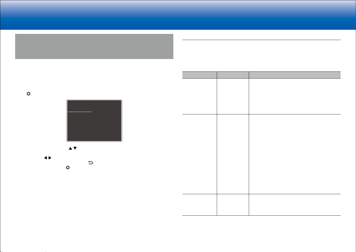
> Specifications > Advanced Setup > Listening Modes > Network Functions > Basic Manual
|Troubleshooting Supplementary Information, etc.
1. Input/Output Assign
Setup Menu
The unit allows you to configure advanced settings to provide you with an even better
experience.
Operation:
Use the on-screen displays (OSD) that appear on the TV to make the settings.
Press
Select the item with the cursor / buttons of the remote controller and press Enter to
confirm your selection.
Use the cursors / to change the default values.
on the remote controller to display the Setup menu.
Setup
1. Input/Output Assign
2. Speaker
3. Audio Adjust
4. Source
5.
Listening Mode Preset
6. Hardware
7. Multi Zone
8. Miscellaneous
•
To return to the previous screen, press .
•
To exit the settings, press .
1. TV Out / OSD
2. HDMI Input
3. Video Input
4. Digital Audio Input
5. Analog Audio Input
Make settings related to output to the TV, change the settings for jack allocations to the
various input selectors, and set the feature for displaying operations on the TV (OSD), etc.
■ 1. TV Out / OSD
Setting Item Default Value Setting Details
HDMI Out MAIN Select the HDMI jack to be connected with the TV.
"MAIN": When connecting the TV to the HDMI OUT
MAIN jack
"SUB": When connecting the TV to the HDMI OUT
SUB jack
"MAIN+SUB": When connecting to both the MAIN
and SUB jacks
Dolby Vision MAIN If you want to output the Dolby Vision video from
the player to a TV that supports Dolby Vision,
select the HDMI OUT jack, MAIN or SUB, to which
you have connected the TV that supports Dolby
Vision. This setting is only necessary if you have
set "HDMI Out" to "MAIN+SUB" and you have
connected a TV to both the MAIN and SUB jacks.
"MAIN": To output Dolby Vision video to a TV that
supports Dolby Vision that is connected to the
HDMI OUT MAIN jack
"SUB": To output Dolby Vision video to a TV that
supports Dolby Vision that is connected to the
HDMI OUT SUB jack
•
If you select "MAIN" or "SUB" but the video on
the TV does not appear correctly, set this to
"Off".
OSD Language English Select the on-screen display language from the
following.
English, German, French, Spanish, Italian, Dutch,
Swedish, Russian, Chinese
7
Page 40
> Specifications > Advanced Setup > Listening Modes > Network Functions > Basic Manual
|Troubleshooting Supplementary Information, etc.
Setting Item Default Value Setting Details
Impose OSD On Set whether or not to display the information on
the TV when the volume is adjusted or input is
changed, for example.
"On": OSD displayed on the TV.
"Off": OSD not displayed on the TV.
•
OSD may not be displayed depending on the
input signal even if "On" is selected. If the
operation screen is not displayed, change the
resolution of the connected device.
Mini Player OSD Always On You can play on the TV the images from another
input selected immediately prior while you are
playing the audio from NET or BLUETOOTH input.
After switching to NET or BLUETOOTH, play the
images and audio, then when you press Mode on
the remote controller, the image is displayed in
full-screen mode, and the audio information (Mini
Player) for NET or BLUETOOTH is displayed in
the corner of the screen. You can set whether to
display this Mini Player on the screen all the time.
"Always On": The Mini Player is displayed all the
time.
"Auto Off": The Mini Player turns off automatically
30 seconds after being displayed. It is displayed for
30 seconds after operations such as changing the
volume.
•
Each press of the Mode button displays or turns
off the video.
•
This cannot be selected if "Impose OSD" is set
to "Off".
Screen Saver 3 minutes Set the time to start the screen saver.
Select a value from "3 minutes", "5 minutes", "10
minutes" and "Off".
■ 2. HDMI Input
You can change input assignment between the input selectors and HDMI IN jacks.
Setting Item Default Value Setting Details
BD/DVD HDMI 1 (HDCP
2.2)
CBL/SAT HDMI 2 (HDCP
2.2)
GAME HDMI 4 (HDCP
2.2)
STRM BOX HDMI 3 (HDCP
2.2)
PC HDMI 5 (HDCP
2.2)
CD --- "HDMI 1 (HDCP 2.2)" to "HDMI 6 (HDCP 2.2)":
"HDMI 1 (HDCP 2.2)" to "HDMI 6 (HDCP 2.2)":
Assign a desired HDMI IN jack to the BD/DVD
button. If you do not assign a jack, select "---".
To select an HDMI IN jack already assigned to
another input selector, change its setting to "---"
first.
"HDMI 1 (HDCP 2.2)" to "HDMI 6 (HDCP 2.2)":
Assign a desired HDMI IN jack to the CBL/SAT
button. If you do not assign a jack, select "---".
To select an HDMI IN jack already assigned to
another input selector, change its setting to "---"
first.
"HDMI 1 (HDCP 2.2)" to "HDMI 6 (HDCP 2.2)":
Assign a desired HDMI IN jack to the Game button.
If you do not assign a jack, select "---". To select
an HDMI IN jack already assigned to another input
selector, change its setting to "---" first.
"HDMI 1 (HDCP 2.2)" to "HDMI 6 (HDCP 2.2)":
Assign a desired HDMI IN jack to the STRM Box
button. If you do not assign a jack, select "---".
To select an HDMI IN jack already assigned to
another input selector, change its setting to "---"
first.
"HDMI 1 (HDCP 2.2)" to "HDMI 6 (HDCP 2.2)":
Assign a desired HDMI IN jack to the PC button. If
you do not assign a jack, select "---". To select an
HDMI IN jack already assigned to another input
selector, change its setting to "---" first.
Assign a desired HDMI IN jack to the CD button.
If you do not assign a jack, select "---". To select
an HDMI IN jack already assigned to another input
selector, change its setting to "---" first.
8
Page 41
> Specifications > Advanced Setup > Listening Modes > Network Functions > Basic Manual
|Troubleshooting Supplementary Information, etc.
Setting Item Default Value Setting Details
TV --- "HDMI 1 (HDCP 2.2)" to "HDMI 6 (HDCP 2.2)":
Assign a desired HDMI IN jack to the TV button. If
you do not assign a jack, select "---". To select an
HDMI IN jack already assigned to another input
selector, change its setting to "---" first.
PHONO --- "HDMI 1 (HDCP 2.2)" to "HDMI 6 (HDCP 2.2)":
Assign a desired HDMI IN jack to the Phono
button. If you do not assign a jack, select "---".
To select an HDMI IN jack already assigned to
another input selector, change its setting to "---"
first.
■ 3. Video Input
You can change input assignment between the input selectors and COMPONENT VIDEO
IN jacks and the VIDEO IN jacks. If you do not assign a jack, select "---".
Setting Item Default Value Setting Details
BD/DVD COMPONENT 1 "COMPONENT 1", "COMPONENT 2": Assign the
COMPONENT VIDEO IN jacks to the BD/DVD
button.
"VIDEO 1", "VIDEO 2": Assign a desired VIDEO IN
jack to the BD/DVD button.
CBL/SAT VIDEO 1 "COMPONENT 1", "COMPONENT 2": Assign the
COMPONENT VIDEO IN jacks to the CBL/SAT
button.
"VIDEO 1", "VIDEO 2": Assign a desired VIDEO IN
jack to the CBL/SAT button.
GAME COMPONENT 2 "COMPONENT 1", "COMPONENT 2": Assign
the COMPONENT VIDEO IN jacks to the Game
button.
"VIDEO 1", "VIDEO 2": Assign a desired VIDEO IN
jack to the Game button.
STRM BOX VIDEO 2 "COMPONENT 1", "COMPONENT 2": Assign the
COMPONENT VIDEO IN jacks to the STRM Box
button.
"VIDEO 1", "VIDEO 2": Assign a desired VIDEO IN
jack to the STRM Box button.
Setting Item Default Value Setting Details
PC --- "COMPONENT 1", "COMPONENT 2": Assign the
COMPONENT VIDEO IN jacks to the PC button.
"VIDEO 1" to "VIDEO 2": Assign a desired VIDEO
IN jack to the PC button.
CD --- "COMPONENT 1", "COMPONENT 2": Assign the
COMPONENT VIDEO IN jacks to the CD button.
"VIDEO 1", "VIDEO 2": Assign a desired VIDEO IN
jack to the CD button.
TV --- "COMPONENT 1", "COMPONENT 2": Assign the
COMPONENT VIDEO IN jacks to the TV button.
"VIDEO 1", "VIDEO 2": Assign a desired VIDEO IN
jack to the TV button.
PHONO --- "COMPONENT 1", "COMPONENT 2": Assign
the COMPONENT VIDEO IN jacks to the Phono
button.
"VIDEO 1", "VIDEO 2": Assign a desired VIDEO IN
jack to the Phono button.
■ 4. Digital Audio Input
You can change input assignment between the input selectors and DIGITAL IN COAXIAL/
OPTICAL jacks. If you do not assign a jack, select "---".
Setting Item Default Value Setting Details
BD/DVD COAXIAL "COAXIAL", "OPTICAL 1", "OPTICAL 2": Assign a
desired DIGITAL IN jack to the BD/DVD button.
CBL/SAT --- "COAXIAL", "OPTICAL 1", "OPTICAL 2": Assign a
desired DIGITAL IN jack to the CBL/SAT button.
GAME --- "COAXIAL", "OPTICAL 1", "OPTICAL 2": Assign a
desired DIGITAL IN jack to the Game button.
STRM BOX --- "COAXIAL", "OPTICAL 1", "OPTICAL 2": Assign a
desired DIGITAL IN jack to the STRM Box button.
PC --- "COAXIAL", "OPTICAL 1", "OPTICAL 2": Assign a
desired DIGITAL IN jack to the PC button.
CD OPTICAL 1 "COAXIAL", "OPTICAL 1", "OPTICAL 2": Assign a
desired DIGITAL IN jack to the CD button.
9
Page 42

> Specifications > Advanced Setup > Listening Modes > Network Functions > Basic Manual
|Troubleshooting Supplementary Information, etc.
Setting Item Default Value Setting Details
TV OPTICAL 2 "COAXIAL", "OPTICAL 1", "OPTICAL 2": Assign a
desired DIGITAL IN jack to the TV button.
PHONO --- "COAXIAL", "OPTICAL 1", "OPTICAL 2": Assign a
desired DIGITAL IN jack to the Phono button.
•
Supported sampling rates for PCM signals (stereo, mono) from a digital input are 32kHz, 44.1kHz,
48kHz, 88.2kHz, 96kHz/16bit, 20bit, and 24bit.
■ 5. Analog Audio Input
You can change input assignment between the input selectors and AUDIO IN jacks. If you
do not assign a jack, select "---".
Setting Item Default Value Setting Details
BD/DVD AUDIO 1 "AUDIO 1" to "AUDIO 6": Assign a desired AUDIO
IN jack to the BD/DVD button.
CBL/SAT AUDIO 2 "AUDIO 1" to "AUDIO 6": Assign a desired AUDIO
IN jack to the CBL/SAT button.
GAME AUDIO 3 "AUDIO 1" to "AUDIO 6": Assign a desired AUDIO
IN jack to the Game button.
STRM BOX AUDIO 4 "AUDIO 1" to "AUDIO 6": Assign a desired AUDIO
IN jack to the STRM Box button.
PC --- "AUDIO 1" to "AUDIO 6": Assign a desired AUDIO
IN jack to the PC button.
CD AUDIO 5 "AUDIO 1" to "AUDIO 6": Assign a desired AUDIO
IN jack to the CD button.
TV AUDIO 6 "AUDIO 1" to "AUDIO 6": Assign a desired AUDIO
IN jack to the TV button.
PHONO PHONO The setting cannot be changed.
10
Page 43
> Specifications > Advanced Setup > Listening Modes > Network Functions > Basic Manual
|Troubleshooting Supplementary Information, etc.
2. Speaker
You can make changes to the connection environment of the speakers and change the
volume level. Settings are automatically configured if you use AccuEQ Room Calibration.
This setting cannot be selected if headphones are connected or audio is output from the
speakers of the TV.
■ 1. Configuration
Setting Item Default Value Setting Details
Speaker
Channels
Subwoofer Yes Set whether a subwoofer is connected or not.
Height Speaker Top Middle Set the speaker type if height speakers are
Zone Speaker No Set the connection of speakers to Zone 2 speaker
7.1 ch Select "2.1 ch", "3.1 ch", "4.1 ch", "5.1 ch", "6.1
ch", "7.1 ch", "2.1.2 ch", "3.1.2 ch", "4.1.2 ch", or
"5.1.2 ch" to suit the number of speaker channels
connected.
"Yes": When subwoofer is connected
"No": When subwoofer is not connected
connected to the SURROUND BACK or HEIGHT
terminals.
Select "Front High", "Top Front", "Top Middle", "Top
Rear", "Rear High", "Dolby Speaker (Front)", or
"Dolby Speaker (Surr)" according to the type and
layout of the connected speakers.
•
If an item cannot be selected even though
connection is correct, check that the settings
in "Speaker Channels" matches the number of
connected channels.
terminals.
"Zone 2": When speakers are connected to Zone 2
speaker terminals
"No": When speakers are not connected to Zone 2
speaker terminals
Setting Item Default Value Setting Details
Bi-Amp No Set whether the front speakers are bi-amp
connected.
"No": When front speakers are not bi-amp
connected
"Yes": When front speakers are bi-amp connected
•
This item will be fixed to "No" when the "Zone
Speaker" setting is "Zone 2".
•
This setting cannot be selected when surround
back speakers or height speakers are installed.
Speaker
Impedance
6ohms Set the impedance (Ω) of the connected speakers.
"4ohms": When any of the connected speakers
have 4 Ω or more to less than 6 Ω impedance
"6ohms": When the connected speakers all have
6 Ω or more impedance.
•
For impedance, check the indications on the
back of the speakers or their instruction manual.
11
Page 44

> Specifications > Advanced Setup > Listening Modes > Network Functions > Basic Manual
|Troubleshooting Supplementary Information, etc.
■ 2. Crossover
Setting Item Default Value Setting Details
Front 100Hz Select the crossover frequency from "40Hz" to
"200Hz" to start outputting frequencies for each
channel.
"Full Band": Full band will be output.
•
If "Configuration" - "Subwoofer" is set to "No",
"Front" will be fixed to "Full Band" and the low
pitched range of the other channels will be
output from the front speakers. Refer to the
instruction manual of your speakers to make the
setting.
Center 100Hz Select the crossover frequency from "40Hz" to
"200Hz" to start outputting frequencies for each
channel.
"Full Band": Full band will be output.
•
"Full Band" can be selected only when "Front" is
set to "Full Band".
•
If an item cannot be selected even though
connection is correct, check that the settings in
"Configuration" - "Speaker Channels" matches
the number of connected channels.
Height 100Hz Select the crossover frequency from "40Hz" to
"200Hz" to start outputting frequencies for each
channel.
"Full Band": Full band will be output.
•
"Full Band" can be selected only when "Front" is
set to "Full Band".
•
If an item cannot be selected even though
connection is correct, check that the settings in
"Configuration" - "Speaker Channels" matches
the number of connected channels.
Setting Item Default Value Setting Details
Surround 100Hz Select the crossover frequency from "40Hz" to
"200Hz" to start outputting frequencies for each
channel.
"Full Band": Full band will be output.
•
"Full Band" can be selected only when "Front" is
set to "Full Band".
•
If an item cannot be selected even though
connection is correct, check that the settings in
"Configuration" - "Speaker Channels" matches
the number of connected channels.
Surround Back 100Hz Select the crossover frequency from "40Hz" to
"200Hz" to start outputting frequencies for each
channel.
"Full Band": Full band will be output.
•
"Full Band" can be selected only when
"Surround" is set to "Full Band".
•
If an item cannot be selected even though
connection is correct, check that the settings in
"Configuration" - "Speaker Channels" matches
the number of connected channels.
LPF of LFE 120Hz Set the low-pass filter for LFE (low-frequency
effect) signals in order to pass lower frequency
signals than the set value and thus cancel
unwanted noises. The low-pass filter will be
effective only on sources with LFE channel.
The value from "80Hz" to "120Hz" can be set.
"Off": When this function is not to be used
Double Bass On This can be selected only when "Configuration"
- "Subwoofer" is set to "Yes" and "Front" is set to
"Full Band".
Boost bass output by feeding bass sounds from
the front left and right, and center speakers to the
subwoofer.
"On": Bass output will be boosted
"Off": Bass output will not be boosted
•
The setting will not automatically be configured
even if you performed AccuEQ Room
Calibration.
12
Page 45

> Specifications > Advanced Setup > Listening Modes > Network Functions > Basic Manual
|Troubleshooting Supplementary Information, etc.
•
■ 3. Distance
Set the distance from each speaker to the listening position.
Setting Item Default Value Setting Details
Front Left 12.0ft/3.60m Specify the distance between each speaker and
the listening position.
Center 12.0ft/3.60m Specify the distance between each speaker and
the listening position.
Front Right 12.0ft/3.60m Specify the distance between each speaker and
the listening position.
Height Left 9.0ft/2.70m Specify the distance between each speaker and
the listening position.
•
The setting cannot be changed if "Zone 2" is set
in "Configuration" - "Zone Speaker" and Zone 2
is on.
Height Right 9.0ft/2.70m Specify the distance between each speaker and
the listening position.
•
The setting cannot be changed if "Zone 2" is set
in "Configuration" - "Zone Speaker" and Zone 2
is on.
Surround Right 7.0ft/2.10m Specify the distance between each speaker and
the listening position.
Surr Back Right 7.0ft/2.10m Specify the distance between each speaker and
the listening position.
•
The setting cannot be changed if "Zone 2" is set
in "Configuration" - "Zone Speaker" and Zone 2
is on.
Surr Back Left 7.0ft/2.10m Specify the distance between each speaker and
the listening position.
•
The setting cannot be changed if "Zone 2" is set
in "Configuration" - "Zone Speaker" and Zone 2
is on.
Surround Left 7.0ft/2.10m Specify the distance between each speaker and
the listening position.
Subwoofer 12.0ft/3.60m Specify the distance between each speaker and
the listening position.
Distance units can be switched by pressing Mode on the remote controller. When the unit is set as
feet, you can set between 0.1 ft and 30.0 ft in increments of 0.1ft. When the unit is set as meters, you
can set between 0.03 m and 9.00 m in increments of 0.03 m.
•
Default values vary depending on the regions.
13
Page 46

> Specifications > Advanced Setup > Listening Modes > Network Functions > Basic Manual
|Troubleshooting Supplementary Information, etc.
■ 4. Level Calibration
Setting Item Default Value Setting Details
Front Left 0 dB Select a value between "−12 dB" and "+12 dB"
(in 1 dB increments). A test tone will be output
each time you change the value. Select the desired
level.
Center 0 dB Select a value between "−12 dB" and "+12 dB"
(in 1 dB increments). A test tone will be output
each time you change the value. Select the desired
level.
Front Right 0 dB Select a value between "−12 dB" and "+12 dB"
(in 1 dB increments). A test tone will be output
each time you change the value. Select the desired
level.
Height Left 0 dB Select a value between "−12 dB" and "+12 dB"
(in 1 dB increments). A test tone will be output
each time you change the value. Select the desired
level.
•
The setting cannot be changed if "Zone 2" is set
in "Configuration" - "Zone Speaker" and Zone 2
is on.
Height Right 0 dB Select a value between "−12 dB" and "+12 dB"
(in 1 dB increments). A test tone will be output
each time you change the value. Select the desired
level.
•
The setting cannot be changed if "Zone 2" is set
in "Configuration" - "Zone Speaker" and Zone 2
is on.
Surround Right 0 dB Select a value between "−12 dB" and "+12 dB"
(in 1 dB increments). A test tone will be output
each time you change the value. Select the desired
level.
Setting Item Default Value Setting Details
Surr Back Right 0 dB Select a value between "−12 dB" and "+12 dB"
(in 1 dB increments). A test tone will be output
each time you change the value. Select the desired
level.
•
The setting cannot be changed if "Zone 2" is set
in "Configuration" - "Zone Speaker" and Zone 2
is on.
Surr Back Left 0 dB Select a value between "−12 dB" and "+12 dB"
(in 1 dB increments). A test tone will be output
each time you change the value. Select the desired
level.
•
The setting cannot be changed if "Zone 2" is set
in "Configuration" - "Zone Speaker" and Zone 2
is on.
Surround Left 0 dB Select a value between "−12 dB" and "+12 dB"
(in 1 dB increments). A test tone will be output
each time you change the value. Select the desired
level.
Subwoofer 0 dB Select a value between "−15 dB" and "+12 dB"
(in 1 dB increments). A test tone will be output
each time you change the value. Select the desired
level.
■ 5. Dolby Enabled Speaker
Setting Item Default Value Setting Details
Dolby Enabled
Speaker to
Ceiling
AccuReflex Off You can enhance the reflection effect of Dolby
6.0 ft/1.80 m Set the distance between the Dolby Enabled
Speaker and the ceiling. Select between "0.1
ft/0.03 m" to "15.0 ft/4.50 m" (0.1 ft/0.03 m units).
•
The unit of distance (ft/m) shown is the unit
selected for use in "Distance".
Enabled Speakers from the ceiling.
"Off": When this function is not to be used
"On": When this function is to be used
14
•
This setting can be selected when "Configuration" - "Height Speaker" is set to "Dolby Speaker".
Page 47

> Specifications > Advanced Setup > Listening Modes > Network Functions > Basic Manual
|Troubleshooting Supplementary Information, etc.
•
■ 6. Equalizer Settings
You can adjust the output volume of the range of each connected speaker. You can adjust
the volume of the different sound ranges for each of the speakers. You can set three
different equalizers in Preset 1 to 3. You can select up to five bands for the Subwoofer and
15 bands for all other speakers.
Setting Item Default Value Setting Details
Front 0 dB After selecting the speaker frequency from
between "25 Hz" and "16 kHz" with the cursors
, adjust the volume of that frequency between
/
"−6 dB" and "+6 dB" with / .
Center 0 dB After selecting the speaker frequency from
between "25 Hz" and "16 kHz" with the cursors
, adjust the volume of that frequency between
/
"−6 dB" and "+6 dB" with / .
Height 0 dB After selecting the speaker frequency from
between "25 Hz" and "16 kHz" with the cursors
, adjust the volume of that frequency between
/
"−6 dB" and "+6 dB" with / .
•
The setting cannot be changed if "Zone 2" is set
in "Configuration" - "Zone Speaker" and Zone 2
is on.
Surround 0 dB After selecting the speaker frequency from
between "25 Hz" and "16 kHz" with the cursors
, adjust the volume of that frequency between
/
"−6 dB" and "+6 dB" with / .
Surround Back 0 dB After selecting the speaker frequency from
between "25 Hz" and "16 kHz" with the cursors
, adjust the volume of that frequency between
/
"−6 dB" and "+6 dB" with / .
•
The setting cannot be changed if "Zone 2" is set
in "Configuration" - "Zone Speaker" and Zone 2
is on.
Subwoofer 0 dB After selecting the speaker frequency from
between "25 Hz" and "160 Hz" with the cursors
, adjust the volume of that frequency between
/
"−6 dB" and "+6 dB" with
•
This cannot be selected if "No" is set in
"Configuration" - "Subwoofer".
/ .
The result may not be as expected depending on the input source and listening mode setting.
15
Page 48
> Specifications > Advanced Setup > Listening Modes > Network Functions > Basic Manual
|Troubleshooting Supplementary Information, etc.
3. Audio Adjust
Make advanced settings such as those related to multiplex audio, settings for the LFE level,
or those related to the volume of this unit.
■ 1. Multiplex/Mono
Setting Item Default Value Setting Details
Multiplex Input
Channel
Mono Input
Channel
Main Set the audio channel or language to be output
when playing multiplex audio or multilingual TV
broadcasts etc.
"Main": Main channel only
"Sub": Sub channel only
"Main/Sub": Main and sub channels will be output
at the same time.
•
If multiplex audio is being played, "1+1" will be
displayed when
pressed.
Left + Right Set the input channel to use for playing any 2 ch
digital source such as Dolby Digital, or 2 ch analog/
PCM source in the Mono listening mode.
"Left": Left channel only
"Right": Right channel only
"Left + Right" : Left and right channels
on the remote controller is
■ 2. Dolby
■ 3. DTS
Setting Item Default Value Setting Details
DTS Auto
Surround
On When inputting DTS signals that include extended
channel information, the optimum listening mode is
automatically selected according to the extended
information contained in the input signal and the
speaker configuration of this unit when playing in
the straight decoding listening mode.
"On": Use this function
"Off": Audio is played using the same amount
of channels in the input signal according to the
speaker configuration of this unit.
•
The ES Matrix and ES Discrete listening modes
cannot be selected if this function is set to "Off".
■ 4. LFE Level
Set the low-frequency effect (LFE) level for Dolby Digital series, DTS series, Multichannel
PCM, and DSD signals.
Setting Item Default Value Setting Details
LFE Level 0dB Select the low-frequency effect (LFE) level of each
type of signal from "0dB" to "−dB". If the lowfrequency effect sound is too strong, select
"−20dB" or "−dB".
Setting Item Default Value Setting Details
Loudness
Management
On When playing Dolby TrueHD, enable the dialog
normalization function which keeps the volume of
dialog at a certain level. Note that when this setting
is Off, the Late Night function that allows you to
enjoy surround at low volumes is fixed to off when
playing Dolby Digital Plus/Dolby TrueHD.
"On": When this function is to be used
"Off": When this function is not to be used
16
■ 5. Volume
Setting Item Default Value Setting Details
Mute Level −dB Set the volume lowered from the listening volume
when muting is on. Select a value from "−dB",
"−40dB", and "−20dB".
Maximum Volume Off Set the maximum value to avoid too high volume.
Select a value from "Off", "50" to "99".
Page 49

> Specifications > Advanced Setup > Listening Modes > Network Functions > Basic Manual
|Troubleshooting Supplementary Information, etc.
Power On Volume Last Set the volume level of when the power is turned
on. Select a value from "Last" (Volume level before
entering standby mode), "Min", "1" to "99" and
"Max".
•
You cannot set a higher value than that of
"Maximum Volume".
Headphone Level 0 dB Adjust the output level of the headphones. Select a
value between "−12 dB" and "+12 dB".
4. Source
Make settings for input sources, such as volume difference adjustments for each input
selector for the connected equipment.
■ 1. IntelliVolume
Adjust the volume level difference between the devices connected to the unit. Select the
input selector to configure.
Setting Item Default Value Setting Details
IntelliVolume 0 dB Select a value between "−12 dB" and "+12 dB".
Set a negative value if the volume of the target
device is larger than the others and a positive
value if smaller. To check the audio, start playback
of the connected device.
•
This function is not effective in Zone 2.
■ 2. Name Edit
Set an easy name to each input. The set name will be shown on the main unit display.
Select the input selector to configure.
Setting Item Default Value Setting Details
Name Edit Input name 1. Select a character or symbol with the cursors
and press Enter.
Repeat it to input 10 or less characters.
"A/a": Switches between upper and lower cases.
(Pressing Mode on the remote controller also
toggles between upper and lower cases)
"←" "→": Moves the cursor to the arrow
direction.
" ": Removes a character on the left of the
cursor.
" ": Enters a space.
•
Pressing Clear on the remote controller will
remove all the input characters.
2. After inputting, select "OK" with the cursors and
press Enter.
The input name will be saved.
17
Page 50
> Specifications > Advanced Setup > Listening Modes > Network Functions > Basic Manual
|Troubleshooting Supplementary Information, etc.
•
To name a preset radio station, press Tuner on the remote controller, select AM/FM and select the
preset number.
•
This cannot be set if the "NET" or "BLUETOOTH" input is selected.
■ Audio Select
Select the priority for input selection when multiple audio sources are connected to one
input selector, such as connections to both the "BD/DVD" HDMI IN jack and the "BD/DVD"
AUDIO IN jack. The setting can be separately set to each input selector button. Select the
input selector to configure. Note that there are some default values you cannot change.
Setting Item Default Value Setting Details
Audio Select BD/DVD:
HDMI
CBL/SAT:
HDMI
GAME:
HDMI
STRM BOX:
HDMI
PC:
HDMI
AUX:
HDMI
CD:
OPTICAL
PHONO:
Analog
TV:
OPTICAL
"ARC": When giving priority to input signal from
ARC compatible TV.
•
The setting can be selected only when
"6. Hardware" - "HDMI" - "Audio Return
Channel" is set to "Auto" and also the "TV" input
is selected.
"HDMI": When giving priority to input signal from
HDMI IN jacks
•
The setting can be selected only when the input
is assigned to the HDMI jack in the "1. Input/
Output Assign" - "HDMI Input" setting.
"COAXIAL": When giving priority to input signal
from DIGITAL IN COAXIAL jacks
•
The setting can be selected only when the input
is assigned to the COAXIAL jack in the "1. Input/
Output Assign" - "Digital Audio Input" setting.
"OPTICAL": When giving priority to input signal
from DIGITAL IN OPTICAL jacks
•
The setting can be selected only when the input
is assigned to the OPTICAL jack in the "1. Input/
Output Assign" - "Digital Audio Input" setting.
"Analog": To always output analog audio
independently of the input signal
•
The setting can be selected only when the
input is assigned to the AUDIO IN jack in the
"1. Input/Output Assign" - "Analog Audio Input"
setting.
Setting Item Default Value Setting Details
PCM Fixed Mode Off Select whether to fix input signals to PCM (except
multi-channel PCM) when you have selected
"HDMI", "COAXIAL", or "OPTICAL" in the "Audio
Select" setting. Set this item to "On" if noise is
produced or truncation occurs at the beginning of
a track when playing PCM sources. Select "Off"
normally.
•
Changing "Audio Select" changes the setting to
"Off".
•
The setting cannot be changed when "TUNER", "NET", or "BLUETOOTH" input is selected.
■ Video Select
When "TUNER", "NET", or "BLUETOOTH" input is selected, you can set the input from
which video is displayed on the TV.
Setting Item Default Value Setting Details
Video Select Last "Last": Select the video input played immediately
prior.
"BD/DVD", "CBL/SAT", "GAME", "STRM BOX",
"PC", "AUX", "CD", "TV", "PHONO": Play the video
from the selected input.
•
This setting is effective for an input selector
which is assigned in "1. Input/Output Assign" "HDMI Input" and "Video Input".
•
If the OSD language is set to Chinese, you can only select this setting when
input.
TUNER" is selected as
"
18
Page 51

> Specifications > Advanced Setup > Listening Modes > Network Functions > Basic Manual
|Troubleshooting Supplementary Information, etc.
5. Listening Mode Preset
You can preset your favorite listening mode to each input. (For example, you can always
apply straight decode to the Dolby TrueHD source of Blu-ray Disc to play it in unchanged
sound field.)
When the list of input sources is displayed, set the signal type and listening mode.
Although it is possible to select the listening mode during playback, the selected mode will
be reset when the unit enters standby mode.
Setting Item Default Value Setting Details
Analog/PCM All Ch Stereo Set the listening mode for playing PCM signals of
CD and analog signals of record and cassette tape.
Dolby Dolby Surround Set the listening mode for playing Dolby Digital,
Dolby Digital Plus and Dolby TrueHD signals.
•
Input signals are played as they are input if you
select "Straight Decode".
DTS
Other Dolby Surround Set the listening mode for playing audio such as
•
Available listening modes vary depending on speaker configuration and the input signal.
•
Setting "Last Valid" will always select the last selected mode.
•
Only "Analog" can be set to the "TUNER" input.
•
"Digital", "Dolby" and "DSD" can be set to the "NET" input.
•
Only "Digital" can be set to the "BLUETOOTH" input.
DTS Neural:X
Set the listening mode for playing digital audio
signals in DTS and DTS-HD High Resolution
formats. Select the listening mode specified for
Blu-ray or such other DTS-HD Master Audio
source.
•
Input signals are played as they are input if you
select "Straight Decode".
DVD-audio and DSD signals.
•
Input signals are played as they are input if you
select "Straight Decode".
6. Hardware
Make settings related to the HDMI CEC, HDMI Standby Through, ARC features, settings
related to network features, and settings related to power management of the unit, such as
Auto Standby and Network Standby, and 12V Trigger jack output settings.
■ 1. HDMI
Setting Item Default Value Setting Details
HDMI CEC Off Setting to "On" enables the input selection link and
other link functions with HDMI connected CEC
compliant device.
"On": When this function is to be used
"Off": When this function is not to be used
When changing this setting, turn off and then on
again the power of all connected components.
•
Depending on the TV set, a link may need to be
configured on the TV.
•
This function is effective only when the device is
connected to the HDMI OUT MAIN terminal.
•
Setting to "On" and closing the on-screen menu
displays the name of the CEC-compatible
components and "CEC On" on the display.
•
Power consumption in standby mode may
increase if "On" is set. (Depending on the TV
status, the unit will enter the normal standby
mode.)
•
If you operate the Master Volume dial on the
main unit when this setting is "On" and audio
is output from the TV speakers, audio will be
output also from the speakers connected to the
unit. If you want to output from only either of
them, change the unit or TV settings, or reduce
the volume of the unit.
•
If abnormal operation occurs when you set the
setting to "On", set it to "Off".
•
When connecting a non-CEC compatible
component, or when you are not sure whether it
is compatible, set the setting to "Off".
19
Page 52
> Specifications > Advanced Setup > Listening Modes > Network Functions > Basic Manual
|Troubleshooting Supplementary Information, etc.
Setting Item Default Value Setting Details
HDMI Standby
Through
Off When this is set to anything other than "Off",
you can play the video and audio of an HDMI
connected player on the TV even if the unit is in
standby mode. Only "Auto" and "Auto(Eco)" can be
selected if "HDMI CEC" is set to "On". If you select
anything else, set "HDMI CEC" to "Off".
•
Power consumption in standby mode increases
if set to anything other than "Off".
"BD/DVD", "CBL/SAT", "GAME", "STRM BOX",
"PC", "AUX", "CD", "TV", "PHONO": For example,
if you select "BD/DVD", you can play the
equipment connected to the "BD/DVD" jack on the
TV even if the unit is in standby mode. Select this
setting if you have decided which player to use with
this function.
"Last": You can play the video and audio of the
input selected immediately prior to the unit being
switched to standby on the TV.
"Auto", "Auto (Eco)": Select one of these settings
when you have connected equipment that
conforms to the CEC standard. You can play the
video and audio of the input selected on the TV,
irrespective of what input was selected immediately
prior to the unit being switched to standby, using
the CEC link function.
•
To play players on the TV that do not conform to
the CEC standard, you will need to turn the unit
on and switch to the relevant input.
•
When using TV that complies with the
CEC standard, you can reduce the power
consumption in standby mode by selecting
"Auto (Eco)".
Setting Item Default Value Setting Details
Audio TV Out Off You can enjoy audio through the speakers of the
TV while this unit is on.
"On": When this function is to be used
"Off": When this function is not to be used
•
This setting is fixed to "Auto" if you have set
"1. Input/Output Assign" - "TV Out/OSD" "HDMI Out" or "Other" - "HDMI Out" in the
"Quick Menu" to "MAIN" or "MAIN+SUB" and
"HDMI CEC" is set to "On". If you change this
setting, set "HDMI CEC" to "Off".
•
Listening mode cannot be changed while "Audio
TV Out" is set to "On" and audio is being output
through the speakers of the TV.
•
Depending on your TV set or input signal of the
component, audio may not output through the
speakers of the TV even if this setting is set
to "On". In such case, audio is output from the
speakers of the unit.
•
If you operate the Master Volume dial on this
unit when audio that is being input through this
unit for output from the TV speakers, audio
is output from this unit. If you do not want to
output audio from the unit, change the unit or TV
settings, or reduce the volume of the unit.
Audio Return
Channel
Auto LipSync On
Auto (*) You can enjoy sound of the HDMI connected ARC
compatible TV through the speakers connected to
the unit.
* To use this function, set "HDMI CEC" to "On" in
advance.
"Auto": When enjoying the TV sound through the
speakers connected to the unit
"Off": When not using the ARC function
This setting automatically corrects any
desynchronization between the video and audio signals
based on data from the HDMI LipSync compatible TV.
"On": Automatic correction will be enabled
"Off": Automatic correction will be disabled
20
Page 53

> Specifications > Advanced Setup > Listening Modes > Network Functions > Basic Manual
|Troubleshooting Supplementary Information, etc.
■ 2. Network
•
When LAN is configured with a DHCP, set "DHCP" to "Enable" to configure the
setting automatically. ("Enable" is set by default) To assign fixed IP addresses to each
components, you must set "DHCP" to "Disable" and assign an address to this unit in
"IP Address" as well as set information related to your LAN, such as Subnet Mask and
Gateway.
Setting Item Default Value Setting Details
Wi-Fi Off(Wired) Connect the unit to network via wireless LAN
router.
"On": Wireless LAN connection
"Off(Wired)": Wired LAN connection
Wi-Fi Setup - You can configure wireless LAN settings by
pressing Enter when "Start" is displayed.
Wi-Fi Status - The information of the connected access point will
be displayed.
"SSID": SSID of the connected access point.
"Signal": Signal strength of the connected access
point.
"Status": Status of the connected access point.
MAC Address - This is the MAC address of this unit.
This value is specific to the component and cannot
be changed.
DHCP Enable "Enable": Auto configuration by DHCP
"Disable": Manual configuration without DHCP
•
If selecting "Disable", you must set "IP Address",
"Subnet Mask", "Gateway", and "DNS Server"
manually.
IP Address 0.0.0.0 Displays/Sets the IP address.
Subnet Mask 0.0.0.0 Displays/Sets the subnet mask.
Gateway 0.0.0.0 Displays/Sets the gateway.
DNS Server 0.0.0.0 Displays/Sets the primary DNS server.
Proxy URL - Displays/Sets the proxy server URL.
Proxy Port 8080 Displays/Sets the proxy server port number when
you enter "Proxy URL".
Setting Item Default Value Setting Details
Friendly Name Integra DRX-3.1
XXXXXX
Change the device name for this unit which is
shown on other devices connected to the network
to an easily recognized name.
1. Press Enter to display the Edit screen.
2. Select a character or symbol with the cursors
and press Enter.
Repeat it to input 31 or less characters.
"A/a": Switches between upper and lower
cases. (Pressing Mode on the remote
controller also toggles between upper and
lower cases.)
"←" "→": Moves the cursor to the arrow
direction.
": Removes a character on the left of the
"
cursor.
" ": Enters a space.
•
Pressing Clear on the remote controller will
remove all the input characters.
3. After inputting, select "OK" with the cursors and
press Enter.
The input name will be saved.
21
Page 54

> Specifications > Advanced Setup > Listening Modes > Network Functions > Basic Manual
|Troubleshooting Supplementary Information, etc.
•
Setting Item Default Value Setting Details
AirPlay Password You can set a password of up to 31 characters so
that only registered users can use AirPlay
1. Press Enter to display the Edit screen.
2. Select a character or symbol with the cursors
and press Enter.
Repeat it to input 31 or less characters.
"A/a": Switches between upper and lower
cases. (Pressing Mode on the remote
controller also toggles between upper and
lower cases.)
"←" "→": Moves the cursor to the arrow
direction.
": Removes a character on the left of the
"
cursor.
" ": Enters a space.
•
To select whether to mask the password
with "*" or display it in plain text, press
Memory on the remote controller.
•
Pressing Clear on the remote controller will
remove all the input characters.
3. After inputting, select "OK" with the cursors and
press Enter.
The input password will be saved.
Usage Data No As a means of improving the quality of our
products and services, we may collect information
about your usage over the network. Select "Yes"
if you agree to our collecting this information.
Select "No" if you do not want us to collect this
information.
•
You can set this after confirming the Privacy
Policy. When you select "Usage Data" and
press Enter, the Privacy Policy is displayed.
(The same screen is displayed once also when
setting up the network connection.) If you agree
to the collection of the information, this setting
also becomes "Yes". Note that if you agree
to the Privacy Policy but select "No" for this
setting, the information will not be collected.
Network Check - You can check the network connection.
Press Enter when "Start" is displayed.
22
R
.
Wait for a while if "Network" cannot be selected. It will appear when the network feature is started.
■ 3. Bluetooth
Setting Item Default Value Setting Details
Bluetooth On Select whether or not to use the BLUETOOTH
function.
"On": Enables connection with a BLUETOOTH
wireless technology enabled device by using the
BLUETOOTH function. Select "On" also when
making various BLUETOOTH settings.
"Off": When not using the BLUETOOTH function
Auto Input
Change
Auto Reconnect On This function automatically reconnects to the
On The input of the unit will automatically be switched
to "BLUETOOTH" when connection is made from
a BLUETOOTH wireless technology enabled
device to the unit.
"On": The input will automatically become
"BLUETOOTH" when a BLUETOOTH wireless
technology enabled device is connected.
"Off": The function is disabled.
•
If the input is not switched automatically, set to
"Off" and change the input manually.
BLUETOOTH wireless technology enabled device
connected last when you change the input to
"BLUETOOTH".
"On": When this function is to be used
"Off": When this function is not to be used
•
This may not work with some BLUETOOTH
wireless technology enabled devices.
Page 55
> Specifications > Advanced Setup > Listening Modes > Network Functions > Basic Manual
|Troubleshooting Supplementary Information, etc.
Setting Item Default Value Setting Details
Pairing
Information
Device - Displays the name of the BLUETOOTH wireless
Status - Displays the status of the BLUETOOTH wireless
•
Wait for a while if "Bluetooth" cannot be selected. It will appear when the BLUETOOTH function is
started up.
- You can initialize the pairing information saved on
this unit.
Pressing Enter when "Clear" is displayed
initializes the pairing information stored in this unit.
•
This function does not initialize the pairing
information on the BLUETOOTH wireless
technology enabled device. When pairing the
unit again with the device, be sure to clear
the pairing information on the BLUETOOTH
wireless technology enabled device in
advance. For information on how to clear the
pairing information, refer to the BLUETOOTH
wireless technology enabled device's
instruction manual.
technology enabled device connected to the unit.
•
The name is not displayed when "Status" is
"Ready" and "Pairing".
technology enabled device connected to the unit.
"Ready": Not paired
"Pairing": Paired
"Connected": Successfully connected
■ 4. Power Management
Setting Item Default Value Setting Details
Sleep Timer Off Allows the unit to enter standby automatically when
the specified time elapses. Select a value from "30
minutes", "60 minutes", and "90 minutes".
"Off": Does not turn the unit to standby
automatically.
Auto Standby On/Off This setting places the unit on standby
automatically after 20 minutes of inactivity without
any video or audio input. (When "USB Power
Out at Standby" or "Network Standby" is on, this
becomes the Hybrid Standby mode which reduces
the increase in power consumption to a minimum.)
"On": The unit will automatically enter standby
mode ("AUTO STBY" will light).
"Off": The unit will not automatically enter standby
mode.
•
"Auto Standby" is displayed on the display and
TV screen 30 seconds before the Auto Standby
comes on.
•
"Auto Standby" does not work when Zone 2 is
active.
•
Default values vary depending on the regions.
Auto Standby in
HDMI Standby
Through
USB Power Out
at Standby
Off Enable or disable "Auto Standby" while "HDMI
Standby Through" is on.
"On": The setting will be enabled.
"Off": The setting will be disabled.
•
This setting cannot be set to "On" if "Auto
Standby" and "HDMI Standby Through" are set
to "Off".
Off Devices connected to the USB port are supplied
with electricity even when this unit is in standby
mode when this function is "On".
•
When using this feature, power consumption
increases even when the unit is on standby,
however, the increase in power consumption
is kept to a minimum by automatically entering
the Hybrid Standby mode, where only essential
circuits are operating.
23
Page 56
> Specifications > Advanced Setup > Listening Modes > Network Functions > Basic Manual
|Troubleshooting Supplementary Information, etc.
Setting Item Default Value Setting Details
Network Standby On When this feature is turned "On", you can turn
on the power of the unit via the network using
an application such as Integra Remote that can
control this unit.
•
When "Network Standby" is used, the power
consumption increases even when the unit
is on standby. However, the increase in
power consumption is kept to a minimum by
automatically entering the Hybrid Standby
mode, where only the essential circuit is
operating.
•
When the connection to the network is lost,
"Network Standby" is disabled to reduce power
consumption. Use the power button on the
remote controller or main unit to turn the unit on
if this happens.
Bluetooth Wakeup Off
•
Wait for a while if "Network Standby" and "Bluetooth Wakeup" cannot be selected. It will appear
when the network feature is started.
This function wakes up the unit on standby by
connecting a BLUETOOTH wireless technology
enabled device.
"On": When this function is to be used
"Off": When this function is not to be used
•
Setting to "On" increases the power
consumption even when the unit is on standby.
However, the increase in power consumption
is kept to a minimum by automatically entering
the Hybrid Standby mode, where only the
essential circuit is operating.
•
This setting is fixed to "Off" if "Bluetooth" "Auto Input Change" is set to "Off".
Setting Item Default Value Setting Details
Delay 0 sec Set after how many seconds the 12V trigger output
will occur in response to the unit's operation. As
some devices cause a large current when they turn
on, delay the output if such devices are connected.
Select a value between "0 sec" to "3 sec".
BD/DVD Main
CBL/SAT Main
GAME Main
Set the 12V trigger output setting to each input.
"Off": No output
"Main": Output when "BD/DVD" is selected as
for main room.
"Zone 2": Output when "BD/DVD" is selected as
for ZONE2.
input
"Main/Zone 2": Output when "BD/DVD" is selected
as input for main room or ZONE2.
Set the 12V trigger output setting to each input.
"Off": No output
"Main": Output when "
main room.
input for
"Zone 2": Output when "
input for ZONE2.
"Main/Zone 2": Output when "
as input for main room or ZONE2
Set the 12V trigger output setting to each input.
"Off": No output
"Main": Output when "
for main room.
"Zone 2": Output when "
for ZONE2.
"Main/Zone 2": Output when "
input for main room or ZONE2
CBL/SAT
GAME
" is selected as
CBL/SAT
GAME
" is selected as
CBL/SAT
.
" is selected as input
" is selected as input
" is selected as
GAME
.
input
" is selected
■ 5. 12V Trigger A
Set when outputting the control signal (maximum 12 V/100 mA) through the 12V TRIGGER
OUT A jack. Different settings can be set for each input selector. You can enable power link
operation when you connect the unit and the external devices equipped with 12V trigger
input jack.
24
Page 57

> Specifications > Advanced Setup > Listening Modes > Network Functions > Basic Manual
|Troubleshooting Supplementary Information, etc.
Setting Item Default Value Setting Details
STRM BOX Main
PC Main
AUX Main
CD Main
Set the 12V trigger output setting to each input.
"Off": No output
"Main": Output when "
input for main room.
"Zone 2": Output when "
input for ZONE2.
"Main/Zone 2": Output when "
selected as input for main room or ZONE2
Set the 12V trigger output setting to each input.
"Off": No output
"Main": Output when "PC" is selected as input for
main room.
"Zone 2": Output when "PC" is selected as input for
ZONE2.
"Main/Zone 2": Output when "PC" is selected as
input for main room or ZONE2
Set the 12V trigger output setting to each input.
"Off": No output
"Main": Output when "
main room
"Zone 2": Output when "
for ZONE2.
"Main/Zone 2": Output when "
input for main room or ZONE2
Set the 12V trigger output setting to each input.
"Off": No output
"Main": Output when "CD" is selected as input for
main room.
"Zone 2": Output when "CD" is selected as input for
ZONE2.
"Main/Zone 2": Output when "CD" is selected as
input for main room or ZONE2
.
STRM BOX
STRM BOX
AUX
AUX
" is selected as
" is selected as
STRM BOX
.
" is selected as input for
" is selected as input
" is selected as
AUX
.
.
" is
.
Setting Item Default Value Setting Details
TV Main
PHONO Main
TUNER Main
NET Main
Set the 12V trigger output setting to each input.
"Off": No output
"Main": Output when "TV" is selected as input for
main room.
"Zone 2": Output when "TV" is selected as input for
ZONE2.
"Main/Zone 2": Output when "TV" is selected as
input for main room or ZONE2
Set the 12V trigger output setting to each input.
"Off": No output
"Main": Output when "
for main room.
"Zone 2": Output when "
input for ZONE2.
"Main/Zone 2": Output when "
as input for main room or ZONE2
Set the 12V trigger output setting to each input.
"Off": No output
"Main": Output when "
for main room.
"Zone 2": Output when "
input for ZONE2.
"Main/Zone 2": Output when "
as input for main room or ZONE2
Set the 12V trigger output setting to each input.
"Off": No output
"Main": Output when "
main room.
"Zone 2": Output when "
for ZONE2.
"Main/Zone 2": Output when "
input for main room or ZONE2
.
" is selected as input
PHONO
" is selected as
PHONO
" is selected
PHONO
.
" is selected as input
TUNER
" is selected as
TUNER
" is selected
TUNER
.
" is selected as input for
NET
" is selected as input
NET
" is selected as
NET
.
25
Page 58

> Specifications > Advanced Setup > Listening Modes > Network Functions > Basic Manual
|Troubleshooting Supplementary Information, etc.
Setting Item Default Value Setting Details
BLUETOOTH Main
Set the 12V trigger output setting to each input.
"Off": No output
"Main": Output when "
input for main room.
"Zone 2": Output when "
as input for ZONE2.
"Main/Zone 2": Output when "
selected as input for main room or ZONE2
BLUETOOTH
BLUETOOTH
" is selected as
" is selected
BLUETOOTH
" is
.
■ 6. 12V Trigger B
Set when outputting the control signal (maximum 12 V/25 mA) through the 12V TRIGGER
OUT B jack. Different settings can be set for each input selector. You can enable power link
operation when you connect the unit and the external devices equipped with 12V trigger
input jack.
Setting Item Default Value Setting Details
Delay 1 sec Set after how many seconds the 12V trigger output
will occur in response to the unit's operation. As
some devices cause a large current when they turn
on, delay the output if such devices are connected.
Select a value between "0 sec" to "3 sec".
BD/DVD Zone 2
Set the 12V trigger output setting to each input.
"Off": No output
"Main": Output when "BD/DVD" is selected as
for main room.
"Zone 2": Output when "BD/DVD" is selected as
for ZONE2.
input
"Main/Zone 2": Output when "BD/DVD" is selected
as input for main room or ZONE2.
input
Setting Item Default Value Setting Details
CBL/SAT Zone 2
GAME Zone 2
STRM BOX Zone 2
PC Zone 2
Set the 12V trigger output setting to each input.
"Off": No output
"Main": Output when "
main room.
input for
"Zone 2": Output when "
input for ZONE2.
"Main/Zone 2": Output when "
as input for main room or ZONE2
Set the 12V trigger output setting to each input.
"Off": No output
"Main": Output when "
for main room.
"Zone 2": Output when "
for ZONE2.
"Main/Zone 2": Output when "
input for main room or ZONE2
Set the 12V trigger output setting to each input.
"Off": No output
"Main": Output when "
input for main room.
"Zone 2": Output when "
input for ZONE2.
"Main/Zone 2": Output when "
selected as input for main room or ZONE2
Set the 12V trigger output setting to each input.
"Off": No output
"Main": Output when "PC" is selected as input for
main room.
"Zone 2": Output when "PC" is selected as input for
ZONE2.
"Main/Zone 2": Output when "PC" is selected as
input for main room or ZONE2
CBL/SAT
GAME
STRM BOX
" is selected as
CBL/SAT
GAME
STRM BOX
" is selected as
CBL/SAT
.
" is selected as input
" is selected as input
" is selected as
GAME
.
" is selected as
" is selected as
STRM BOX
.
" is selected
" is
.
26
Page 59
> Specifications > Advanced Setup > Listening Modes > Network Functions > Basic Manual
|Troubleshooting Supplementary Information, etc.
Setting Item Default Value Setting Details
AUX Zone 2
CD Zone 2
TV Zone 2
PHONO Zone 2
Set the 12V trigger output setting to each input.
"Off": No output
"Main": Output when "
main room
"Zone 2": Output when "
for ZONE2.
"Main/Zone 2": Output when "
input for main room or ZONE2
Set the 12V trigger output setting to each input.
"Off": No output
"Main": Output when "CD" is selected as input for
main room.
"Zone 2": Output when "CD" is selected as input for
ZONE2.
"Main/Zone 2": Output when "CD" is selected as
input for main room or ZONE2
Set the 12V trigger output setting to each input.
"Off": No output
"Main": Output when "TV" is selected as input for
main room.
"Zone 2": Output when "TV" is selected as input for
ZONE2.
"Main/Zone 2": Output when "TV" is selected as
input for main room or ZONE2
Set the 12V trigger output setting to each input.
"Off": No output
"Main": Output when "
for main room.
"Zone 2": Output when "
input for ZONE2.
"Main/Zone 2": Output when "
as input for main room or ZONE2
.
" is selected as input for
AUX
" is selected as input
AUX
" is selected as
AUX
.
.
.
" is selected as input
PHONO
" is selected as
PHONO
" is selected
PHONO
.
Setting Item Default Value Setting Details
TUNER Zone 2
NET Zone 2
BLUETOOTH Zone 2
Set the 12V trigger output setting to each input.
"Off": No output
"Main": Output when "
for main room.
"Zone 2": Output when "
input for ZONE2.
"Main/Zone 2": Output when "
as input for main room or ZONE2
Set the 12V trigger output setting to each input.
"Off": No output
"Main": Output when "
main room.
"Zone 2": Output when "
for ZONE2.
"Main/Zone 2": Output when "
input for main room or ZONE2
Set the 12V trigger output setting to each input.
"Off": No output
"Main": Output when "
input for main room.
"Zone 2": Output when "
as input for ZONE2.
"Main/Zone 2": Output when "
selected as input for main room or ZONE2
" is selected as input
TUNER
" is selected as
TUNER
" is selected
TUNER
.
" is selected as input for
NET
" is selected as input
NET
" is selected as
NET
.
BLUETOOTH
BLUETOOTH
" is selected as
" is selected
BLUETOOTH
" is
.
■ 7. 12V Trigger C
Set when outputting the control signal (maximum 12 V/25 mA) through the 12V TRIGGER
OUT C jack. Different settings can be set for each input selector. You can enable power link
operation when you connect the unit and the external devices equipped with 12V trigger
input jack.
27
Page 60

> Specifications > Advanced Setup > Listening Modes > Network Functions > Basic Manual
|Troubleshooting Supplementary Information, etc.
Setting Item Default Value Setting Details
Delay 2 sec Set after how many seconds the 12V trigger output
will occur in response to the unit's operation. As
some devices cause a large current when they turn
on, delay the output if such devices are connected.
Select a value between "0 sec" to "3 sec".
BD/DVD Main/Zone 2
CBL/SAT Main/Zone 2
GAME Main/Zone 2
Set the 12V trigger output setting to each input.
"Off": No output
"Main": Output when "BD/DVD" is selected as
for main room.
"Zone 2": Output when "BD/DVD" is selected as
for ZONE2.
input
"Main/Zone 2": Output when "BD/DVD" is selected
as input for main room or ZONE2.
Set the 12V trigger output setting to each input.
"Off": No output
"Main": Output when "
main room.
input for
"Zone 2": Output when "
input for ZONE2.
"Main/Zone 2": Output when "
as input for main room or ZONE2
Set the 12V trigger output setting to each input.
"Off": No output
"Main": Output when "
for main room.
"Zone 2": Output when "
for ZONE2.
"Main/Zone 2": Output when "
input for main room or ZONE2
CBL/SAT
GAME
" is selected as
CBL/SAT
GAME
" is selected as
CBL/SAT
.
" is selected as input
" is selected as input
" is selected as
GAME
.
input
" is selected
Setting Item Default Value Setting Details
STRM BOX Main/Zone 2
PC Main/Zone 2
AUX Main/Zone 2
CD Main/Zone 2
Set the 12V trigger output setting to each input.
"Off": No output
"Main": Output when "
input for main room.
"Zone 2": Output when "
input for ZONE2.
"Main/Zone 2": Output when "
selected as input for main room or ZONE2
Set the 12V trigger output setting to each input.
"Off": No output
"Main": Output when "PC" is selected as input for
main room.
"Zone 2": Output when "PC" is selected as input for
ZONE2.
"Main/Zone 2": Output when "PC" is selected as
input for main room or ZONE2
Set the 12V trigger output setting to each input.
"Off": No output
"Main": Output when "
main room
"Zone 2": Output when "
for ZONE2.
"Main/Zone 2": Output when "
input for main room or ZONE2
Set the 12V trigger output setting to each input.
"Off": No output
"Main": Output when "CD" is selected as input for
main room.
"Zone 2": Output when "CD" is selected as input for
ZONE2.
"Main/Zone 2": Output when "CD" is selected as
input for main room or ZONE2
.
STRM BOX
STRM BOX
AUX
AUX
" is selected as
" is selected as
STRM BOX
.
" is selected as input for
" is selected as input
AUX
.
.
" is
.
" is selected as
28
Page 61

> Specifications > Advanced Setup > Listening Modes > Network Functions > Basic Manual
|Troubleshooting Supplementary Information, etc.
Setting Item Default Value Setting Details
TV Main/Zone 2
PHONO Main/Zone 2
TUNER Main/Zone 2
NET Main/Zone 2
Set the 12V trigger output setting to each input.
"Off": No output
"Main": Output when "TV" is selected as input for
main room.
"Zone 2": Output when "TV" is selected as input for
ZONE2.
"Main/Zone 2": Output when "TV" is selected as
input for main room or ZONE2
Set the 12V trigger output setting to each input.
"Off": No output
"Main": Output when "
for main room.
"Zone 2": Output when "
input for ZONE2.
"Main/Zone 2": Output when "
as input for main room or ZONE2
Set the 12V trigger output setting to each input.
"Off": No output
"Main": Output when "
for main room.
"Zone 2": Output when "
input for ZONE2.
"Main/Zone 2": Output when "
as input for main room or ZONE2
Set the 12V trigger output setting to each input.
"Off": No output
"Main": Output when "
main room.
"Zone 2": Output when "
for ZONE2.
"Main/Zone 2": Output when "
input for main room or ZONE2
.
" is selected as input
PHONO
" is selected as
PHONO
" is selected
PHONO
.
" is selected as input
TUNER
" is selected as
TUNER
" is selected
TUNER
.
" is selected as input for
NET
" is selected as input
NET
" is selected as
NET
.
Setting Item Default Value Setting Details
BLUETOOTH Main/Zone 2
Set the 12V trigger output setting to each input.
"Off": No output
"Main": Output when "
input for main room.
"Zone 2": Output when "
as input for ZONE2.
"Main/Zone 2": Output when "
selected as input for main room or ZONE2
BLUETOOTH
BLUETOOTH
BLUETOOTH
" is selected as
" is selected
" is
.
29
Page 62

> Specifications > Advanced Setup > Listening Modes > Network Functions > Basic Manual
|Troubleshooting Supplementary Information, etc.
7. Multi Zone
Make settings related to Multi-zone Connection, such as the volume for the separate room.
■ 1. Zone 2
Setting Item Default Value Setting Details
Output Level Fixed Select whether to adjust the volume on the pre-
main amplifier in the separate room or on this unit
when outputting to Zone 2.
"Fixed": Adjust on the pre-main amplifier in the
separate room
"Variable": Adjust on this unit
Maximum Volume Off Set the maximum value for Zone 2 to avoid too
high volume. Select a value from "Off", "50" to "99".
Power On Volume Last Set the Zone 2 volume level of when this unit is
turned on. Select a value from "Last" (Volume level
when the unit was turned off), "Min", "1" to "99" and
"Max".
•
You cannot set a higher value than that of
"Maximum Volume".
■ 2. Remote Play Zone
Setting Item Default Value Setting Details
Remote Play
Zone
Auto When playing using AirPlay or Spotify Connect,
or when using the Music Server feature to play
remotely from your PC, you can set whether to
play in the main room (where this unit is) or in a
separate room (ZONE 2).
"Auto": When the main room input selector is
NET, music is played in the main room. When the
separate room input selector is NET and the main
room is other than NET, then the music is played in
the separate room.
"Main", "Zone2": Select when limiting the play zone
to a particular room. For example, when playing
only in the separate room, select "Zone 2".
•
This feature may not work if something is
already being played with the same network
feature.
30
Page 63

> Specifications > Advanced Setup > Listening Modes > Network Functions > Basic Manual
|Troubleshooting Supplementary Information, etc.
8. Miscellaneous
Change the frequency step for the tuner, update the firmware, and perform Initial Setup,
etc.
■ 1. Tuner
Setting Item Default Value Setting Details
AM / FM
Frequency Step
(North American
models)
AM Frequency
Step (Australian
models)
10 kHz / 0.2 MHz
9 kHz Select a frequency step depending on your area of
Select a frequency step depending on your area of
residence.
Select "10 kHz/0.2 MHz" or "9 kHz/0.05 MHz".
•
When this setting is changed, all radio presets
are deleted.
residence.
Select "10 kHz" or "9 kHz".
•
When this setting is changed, all radio presets
are deleted.
■ 2. Remote ID
Setting Item Default Value Setting Details
Remote ID 1 Select an ID for the unit's remote controller from
"1", "2", and "3" to prevent interference between
the unit and other Integra/ONKYO components that
are installed in the same room. After changing the
ID on the main unit, change the ID on the remote
controller accordingly with the following procedure.
■ 3. Firmware Update
Setting Item Default Value Setting Details
Update Notice Enable Availability of a firmware update will be notified via
network.
"Enable": Notify updates
"Disable": Disable notifications
Version - The current firmware version will be displayed.
Update via
NET
Update via
USB
•
Wait for a while if "Firmware Update" cannot be selected. It will appear when the network feature is
started.
- Press Enter to select when you want to update the
firmware via network.
•
You will not be able to select this setting if you
do not have Internet access or there is nothing
to update.
- Press Enter to select when you want to update the
firmware via USB.
•
You will not be able to select this setting if a
USB storage device is not connected or there is
nothing to update in the USB storage device.
■ 4. Initial Setup
You can make the initial setup from the setup menu.
•
Wait for a while if "Initial Setup" cannot be selected. It will appear when the network
feature is started.
■ 5. Lock
While holding down Mode, press the following
buttons for about 3 seconds.
•
To change the remote controller ID to "1":
(The remote indicator flashes once.)
•
To change the remote controller ID to "2":
(The remote indicator flashes twice.)
•
To change the remote controller ID to "3":
(The remote indicator flashes three times.)
Setting Item Default Value Setting Details
Setup Parameter Unlocked Lock the Setup menu to protect the settings.
"Locked": The menu is locked.
"Unlocked": The menu is unlocked.
31
Page 64
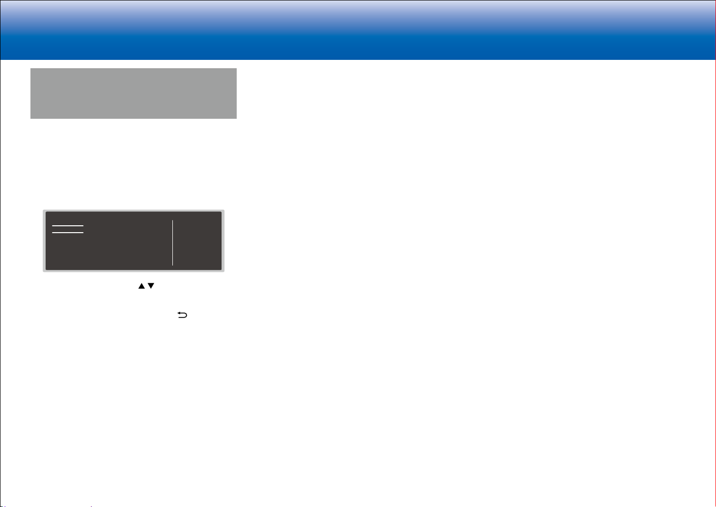
> Specifications > Advanced Setup > Listening Modes > Network Functions > Basic Manual
|Troubleshooting Supplementary Information, etc.
Quick Menu
You can quickly adjust settings you frequently use, such as
tone adjustments, etc.
Operation:
You can make the settings on the TV screen while playing
something. Press Q on the remote controller to display the
Quick Menu.
Quick Menu
Tone
Level
AccuEQ
Other
Bass
Treble
Select the item with the cursor / buttons of the remote
controller and press Enter to confirm your selection.
Use the cursors to change the settings.
•
To return to the previous screen, press .
•
To exit the settings, press Q.
■ Tone
Bass:
Enhance or moderate the bass range of the front speakers.
Treble:
Enhance or moderate the treble range of the front
speakers.
•
It cannot be set if the listening mode is Direct.
■ Level
Center:
Adjust the speaker level of the center speaker while
listening to some sound.
BD/DVD
Subwoofer:
Adjust the speaker level of the subwoofer while listening to
some sound.
•
The adjustment you made will be reset to the previous
status when you turn the unit to standby mode.
■ AccuEQ
AccuEQ Room Calibration:
Enable or disable the equalizer function that corrects for
distortion caused by the acoustic environment of the room.
If this is to be enabled, then normally you should select
"On (All Ch)", and to disable just the front speakers you
should select "On (ex. L/R)". The setting can be separately
set to each input selector.
Equalizer:
Select "Preset 1" to "Preset 3" configured in "2. Speaker" "Equalizer Settings" in the Setup menu. The same sound
field setting is applied all ranges when set to "Off".
Cinema Filter:
Adjust the soundtrack that was processed to enhance
its high pitch range, in order to make it suitable for home
theater. This function can be used in the following listening
modes: Dolby Digital, Dolby Digital Plus, Dolby Surround,
Dolby TrueHD, Multichannel, DTS, DTS-ES, DTS 96/24,
DTS-HD High Resolution Audio, DTS-HD Master Audio,
DTS Neural:X, DTS Express and DSD.
•
It cannot be set if the listening mode is Direct.
■ Other
A/V Sync:
If the video is behind the audio, you can delay the audio to
offset the gap. Different settings can be set for each input
selector.
•
It cannot be set if the listening mode is Direct.
Music Optimizer:
Improve the quality of the compressed audio. Playback
sound of lossy compressed files such as MP3 will be
improved. The setting can be separately set to each input
selector. The setting is effective in the signals of 48 kHz or
less. The setting is not effective in the bitstream signals.
•
It cannot be set if the listening mode is Direct.
Late Night:
Make small sounds easily heard. It is useful when you
need to reduce the volume while watching a movie late
night. You can enjoy the effect only when playing Dolby
series and DTS series input signals.
•
The setting cannot be used in the following cases.
–
If "Loudness Management" is set to "Off" when
playing Dolby Digital Plus or Dolby TrueHD
–
When the input signal is DTS:X and "Dialog Control"
is other than 0 dB
Center Spread:
Adjust the width of the sound field of the front channel
when playing in the Dolby Surround listening mode. To
spread the width of the sound field to the left and right, set
to "On". To concentrate sound in the center, set to "Off".
•
Depending on the speaker settings, this becomes "Off".
Dialog Control:
You can increase the dialog portion of the audio in 1 dB
steps up to 6 dB so that you can make dialog easier to
hear over background noise.
•
This cannot be set for content other than DTS:X.
•
The effect may not be selectable with some content.
HDMI Out:
Allows you to select the HDMI jack to output video signals
from "MAIN", "SUB", and "MAIN+SUB".
32
Page 65

> Specifications > Advanced Setup > Listening Modes > Network Functions > Basic Manual
|Troubleshooting Supplementary Information, etc.
the MAC address and IP address for this unit.
Web Setup
You can make the settings for network features for this unit
in an internet browser on a PC, smartphone, etc.
1. Press
menu.
2. Select "6. Hardware" - "Network" with the cursors, then
take a note of the IP address displayed in "IP Address".
3. Start the internet browser on your PC or smartphone
and enter the IP address of the unit in the URL field.
4. Information for the unit (Web Setup screen) is displayed
in the internet browser.
on the remote controller to display the Setup
Network Connection: You can select how to connect to the
network. If you select "Wireless", select an access point
from "Wi-Fi Setup" to connect.
DHCP: You can change DHCP settings. If you select "Off",
set "IP Address", "Subnet Mask", "Gateway", and "DNS
Server" manually.
Proxy: Display and set the URL for the proxy server.
5. After changing the settings, select "Save" to save the
settings.
Device Information
You can change the Friendly Name, set an AirPlay
Password, etc.
Control4: Register this unit if you are using a Control4
system.
Firmware Update: Select the firmware update you have
downloaded to your PC so you can update this unit.
Network Setting
Status: You can see information for the network such as
33
Page 66
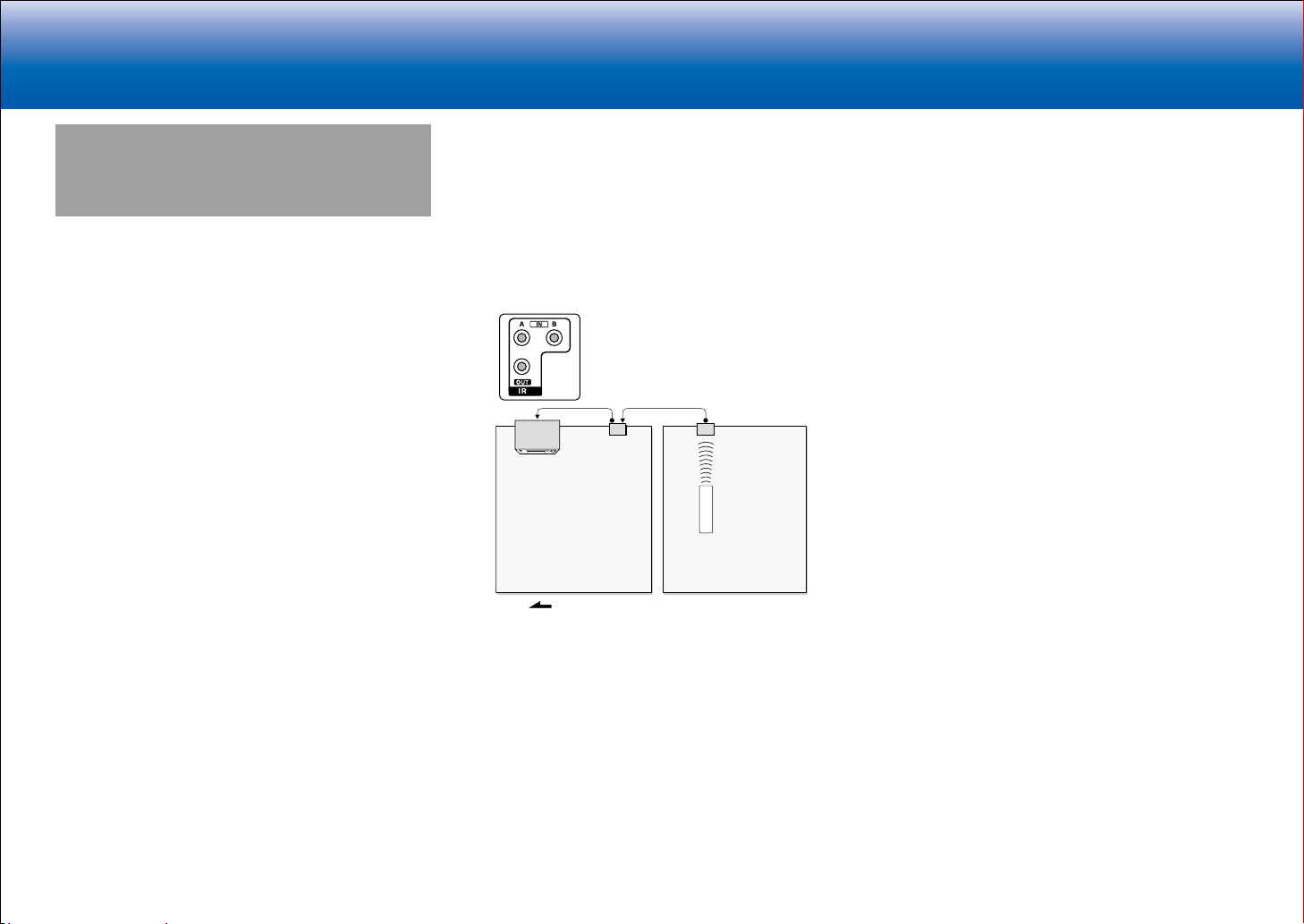
> Specifications > Advanced Setup > Listening Modes > Network Functions > Basic Manual
Signal flow
|Troubleshooting Supplementary Information, etc.
Control Function Settings
You can enable the control functions between the unit and
external devices. Special devices or cable connections are
necessary to enable the functions. For more information
about installation, contact a store specializing in these
products.
■ RS232 port
Use this port for connection with an integrated control
system that can enable home automation. Some integrated
control systems provide a centralized operation with a
single touch panel controller in order to control audio and
video home appliances and security devices together. For
more information about adopting an integrated control
system, contact the specialized stores.
■ IR jack
If you use a commercially available multiroom remote
control kit with this jack, you can operate the unit with
the remote controller even when you are in a separate
room, or operate the unit with the remote controller even
if its remote control sensor is difficult to see. You can also
connect a device with the unit and operate it with the
remote controller.
Connecting
This unit
•
Other companies may use indications other than IR
on their products. Confirm in the instruction manual
included with your components.
•
Refer to the instruction manual of the IR receiver for the
types of cables required for connection.
block
IR receiver
Remote
controller
ZoneMain room
■ 12V trigger output jack
You can enable power link operation when you connect
the unit and an external device such as power amplifier
equipped with 12V trigger input jack. When the desired
input is selected on the unit, power link operation will be
activated with a control signal of maximum 12 V/100 mA
from the 12V TRIGGER OUT A jack or maximum 12 V/25
mA when using the 12V TRIGGER OUT B or C jack. You
can select the zone to output the control signal by setting
each of the inputs. For connection, use a monaural mini
plug cable without a resistor.
34
Page 67

> Specifications > Advanced Setup > Listening Modes > Network Functions > Basic Manual
Power amplifier
|Troubleshooting Supplementary Information, etc.
Connecting a Power Amplifier
You can connect a power amplifier to the unit and use the
unit as a pre-amplifier in order to produce a large volume
that cannot be output with the unit only. Connect the
speakers to the power amplifier. For details, refer to the
power amplifier's instruction manual.
■ Connections
1. Connect as below using the PRE OUT terminals.
•
Set to suit the number of speaker channels
connected.
−
Press
the Setup menu. Select "2. Speaker" "Configuration" - "Speaker Channels" in order
with the cursors, and set the number of speaker
channels.
on the remote controller to display
35
Page 68
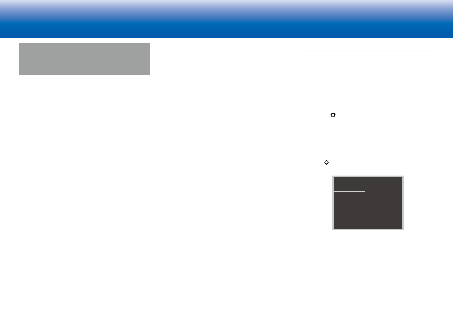
> Specifications > Advanced Setup > Listening Modes > Network Functions > Basic Manual
|Troubleshooting Supplementary Information, etc.
Firmware Update
The updating function on this unit
This unit has functionality to update the firmware (the
system software) over a network or by the USB port.
This enables us to make improvements to a variety of
operations and to add features.
•
For the latest information on updates, visit our
company's website. There is no need to update the
firmware on this unit if there is no update available.
•
Before updating, make sure that the speaker setup
microphone is not connected.
•
During an update, do not
–
Disconnect and reconnect any cable, USB storage
device, speaker setup microphone or headphones,
or perform any operation on the component such as
turn off its power
–
Accessing this unit from a PC or smartphone using
an application
•
The update may take about 20 minutes to complete for
either method: via network or via USB. Furthermore,
existing settings are guaranteed regardless of the
method used for update.
Note that when this unit is connected to a network, you
may see notifications about firmware updates on the
display. To execute updating, select "Update Now" with the
cursor buttons of the remote controller and press Enter.
The unit automatically turns itself into standby mode after
"Completed!" appears on the display, and updating will be
complete.
concerning your use of the program or the accompanying
online documentation, regardless of legal theory, and
whether arising in tort or contract.
In no event will our company be liable to you or any third
party for any special, indirect, incidental, or consequential
damages of any kind, including, but not limited to,
compensation, reimbursement or damages on account of
the loss of present or prospective profits, loss of data, or
for any other reason whatsoever.
Updating the Firmware via Network
Preparation:
•
Check that the unit is turned on, and the connection to
the Internet is secured.
•
Turn off the controller component (PC etc.) connected
to the network.
•
Stop any playing Internet radio, USB storage device, or
server content.
•
If the multi-zone function is active, turn it off.
•
If "HDMI CEC" is set to "On", set it to "Off".
–
Press
on the remote controller. Then, after
selecting "6. Hardware" - "HDMI" and pressing Enter,
select "HDMI CEC" and select "Off".
* The description may differ from the on-screen display but that will not
change the way to operate or the function.
■ Update
1. Press on the remote controller.
The Setup menu is displayed on the TV screen.
Setup
1. Input/Output Assign
2. Speaker
3. Audio Adjust
4. Source
5.
Listening Mode Preset
6. Hardware
7. Multi Zone
8. Miscellaneous
2. Select "8. Miscellaneous" - "Firmware Update" "Update via NET" with the cursors in order, then press
Enter.
1. TV Out / OSD
2. HDMI Input
3. Video Input
4. Digital Audio Input
5. Analog Audio Input
Disclaimer: The program and accompanying online
documentation are furnished to you for use at your own
risk.
Our company will not be liable and you will have no
remedy for damages for any claim of any kind whatsoever
36
Page 69
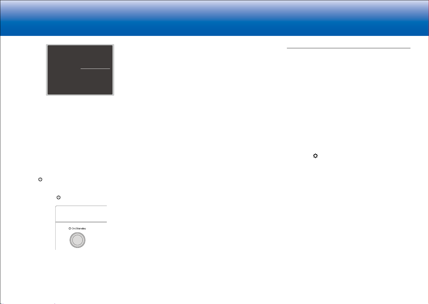
> Specifications > Advanced Setup > Listening Modes > Network Functions > Basic Manual
|Troubleshooting Supplementary Information, etc.
Setup
1. Input/Output Assign
2. Speaker
3. Audio Adjust
4. Source
5.
Listening Mode Preset
6. Hardware
7. Multi Zone
8. Miscellaneous
•
If "Firmware Update" is grayed out and cannot be
1. Tuner
2. Remote ID
3. Firmware Update
4. Initial Setup
5. Lock
selected, wait for a while until it starts up.
•
You will not be able to select "Update via NET" if
there is nothing to update.
3. Press Enter with "Update" selected to start update.
•
During the update, the TV screen may go black
depending on the updated program. In that case,
check the progress on the display of the unit. The
TV screen will remain black until the update is
complete and the power is turned on again.
•
"Completed!" is displayed when the update is
complete.
4. Press
On/Standby on the main unit to turn the unit
into standby mode. The process is completed and your
firmware is updated to the latest version.
•
Do not use on the remote controller.
Error Code
•
*-01, *-10:
Ethernet cable not found. Connect the Ethernet cable
properly.
•
*-02, *-03, *-04, *-05, *-06, *-11, *-13, *-14, *
-16, *-17, *-18, *-20, *-21:
Internet connection error. Check the following:
–
The router is turned on
–
This unit and the router are connected via the
network
Try to disconnect and then connect again the power
to the unit and router. This may solve the problem. If
you are still unable to connect to the Internet, the DNS
server or proxy server may be temporarily down. Check
the service status with your ISP provider.
•
Others
Disconnect then reconnect the AC power cord, then
repeat from the beginning.
Updating via USB
Preparation:
•
Prepare a 128MB or larger USB storage device. FAT16
or FAT32 file system format.
–
Media inserted in a USB card reader may not be
used for this function.
–
USB storage devices with security function are not
supported.
–
USB hubs and USB devices with hub function are
not supported. Do not connect these devices to the
unit.
•
Delete any data stored on the USB storage device.
•
Turn off the controller component (PC etc.) connected
to the network.
•
Stop any playing Internet radio, USB storage device, or
server content.
•
If the multi-zone function is active, turn it off.
•
If "HDMI CEC" is set to "On", set it to "Off".
–
Press
selecting "6. Hardware" - "HDMI" and pressing Enter,
select "HDMI CEC" and select "Off".
* Some USB storage devices may take long to load, may not be loaded
correctly, or may not be correctly fed depending on the device or their
content.
* Our company will not be liable whatsoever for any loss or damage of
data, or storage failure arising from the use of the USB storage device
with this unit. Thank you for your understanding.
* The description may differ from the on-screen display but that will not
change the way to operate or the function.
on the remote controller. Then, after
■ If an Error Message is Displayed
When an error occurs, "*-** Error!" is displayed on
the display of the unit. ("*" represents an alphanumeric
character.) Check the following:
■ Update
1. Connect the USB storage device to your PC.
2. Download the firmware file from our company's website
to your PC and unzip.
Firmware files are named in the following way:
ONKAVR****_************.zip
Unzip the file on your PC. The number of unzipped files
and folders varies depending on the model.
3. Copy all unzipped files and folders to the root folder of
the USB storage device.
•
Make sure to copy the unzipped files.
37
Page 70
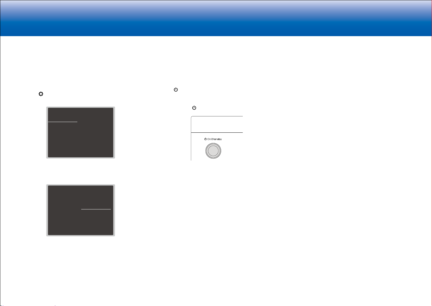
> Specifications > Advanced Setup > Listening Modes > Network Functions > Basic Manual
|Troubleshooting Supplementary Information, etc.
4. Connect the USB storage device to the USB port of the
unit.
•
If you connect a USB hard disk drive to the USB
port of the unit, we recommend that you use its AC
adapter to power it.
•
If the USB storage device has been partitioned,
each section will be treated as an independent
device.
5. Press
on the remote controller.
The Setup menu is displayed on the TV screen.
Setup
1. Input/Output Assign
2. Speaker
3. Audio Adjust
4. Source
5.
Listening Mode Preset
6. Hardware
7. Multi Zone
8. Miscellaneous
1. TV Out / OSD
2. HDMI Input
3. Video Input
4. Digital Audio Input
5. Analog Audio Input
6. Select "8. Miscellaneous" - "Firmware Update" "Update via USB" with the cursors in order, then press
Enter.
Setup
1. Input/Output Assign
2. Speaker
3. Audio Adjust
4. Source
5.
Listening Mode Preset
6. Hardware
7. Multi Zone
8. Miscellaneous
•
If "Firmware Update" is grayed out and cannot be
1. Tuner
2. Remote ID
3. Firmware Update
4. Initial Setup
5. Lock
selected, wait for a while until it starts up.
•
You will not be able to select "Update via USB" if
there is nothing to update.
7. Press Enter with "Update" selected to start update.
•
During the update, the TV screen may go black
depending on the updated program. In that case,
check the progress on the display of the unit. The
38
TV screen will remain black until the update is
complete and the power is turned on again.
•
During the update, do not turn off, or disconnect
then reconnect the USB storage device.
•
"Completed!" is displayed when the update is
complete.
8. Disconnect the USB storage device from the unit.
9. Press
On/Standby on the main unit to turn the unit
into standby mode. The process is completed and your
firmware is updated to the latest version.
•
Do not use on the remote controller.
■ If an Error Message is Displayed
When an error occurs, "*-** Error!" is displayed on
the display of the unit. ("*" represents an alphanumeric
character.) Check the following:
Error Code
•
*-01, *-10:
USB storage device not found. Check whether the USB
storage device or USB cable is correctly inserted to the
USB port of the unit.
Connect the USB storage device to an external power
source if it has its own power supply.
•
*-05, *-13, *-20, *-21:
The firmware file is not present in the root folder of the
USB storage device, or the firmware file is for another
model. Retry from the download of the firmware file.
•
Others
Disconnect then reconnect the AC power cord, then
repeat from the beginning.
Page 71
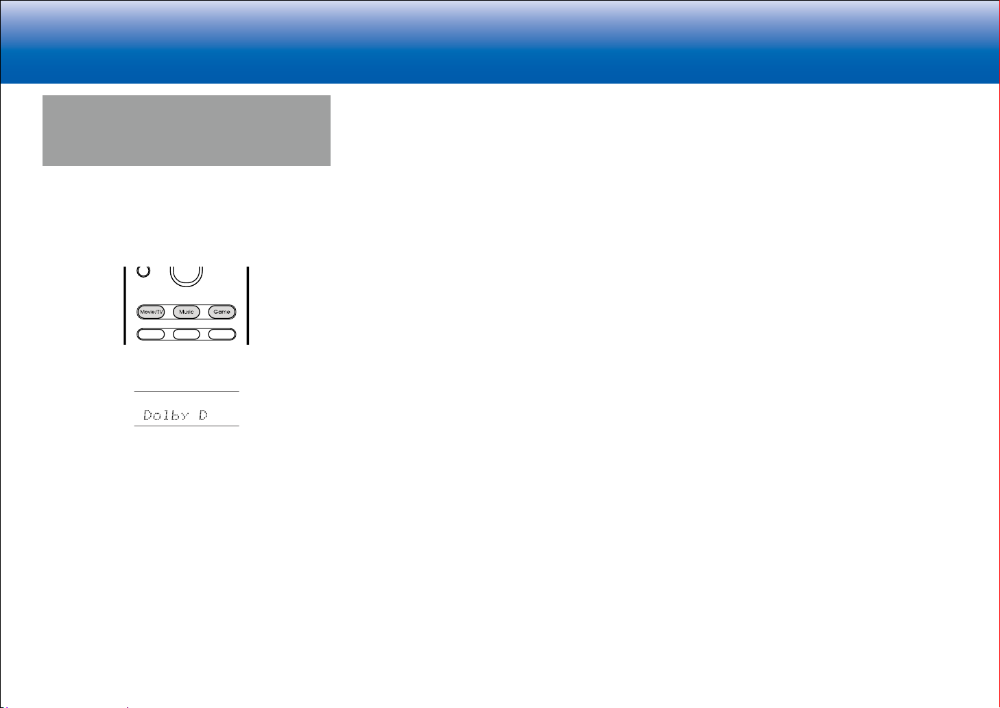
> Specifications > Advanced Setup > Listening Modes > Network Functions > Basic Manual
|Troubleshooting Supplementary Information, etc.
Selecting Listening Modes
Select the optimum listening mode for movies, TV, music,
and games by repeatedly pressing the Movie/TV, Music,
and Game buttons.
1. During play, press one of the following three buttons on
the remote controller.
2. Press the selected button repeatedly to switch the
modes displayed on the display of the unit.
For details on the effects of each of the listening modes
see "Listening Mode Effects". For listening modes
selectable for each of the audio formats in the input
signals, refer to "Selectable Listening Modes".
39
Page 72
> Specifications > Advanced Setup > Listening Modes > Network Functions > Basic Manual
|Troubleshooting Supplementary Information, etc.
Listening Mode Effects
In alphabetical order
■ AllCh Stereo
This mode is ideal for background music. Stereo sound is
played through the surround speakers as well as the front
speakers, creating a stereo image.
■ Direct
This listening mode can be selected for all input signals.
Processing that affects sound quality is shut down so
sound closer to the original is reproduced. Speakers play
the sound field according to the number of channels in the
input signal, so there would be output from only the front
speakers for a two-channel signal, for example.
■ Dolby Atmos
This mode faithfully reproduces the sound design recorded
in the Dolby Atmos audio format.
The Dolby Atmos audio format has been implemented
in movie theaters equipped with the latest facilities and
enables a revolutionary sound experience in home
theaters. Unlike existing surround systems, Dolby Atmos
doesn't rely on channels, but rather enables the accurate
placement of sound objects that have independent
motion in a three-dimensional space with even greater
clarity. Dolby Atmos is an optional audio format on Bluray Discs and achieves a three-dimensional sound field by
introducing a sound field above the listener.
•
To enable transfer of this audio format, connect via
HDMI cable and set audio output on the player to
bitstream output.
■ Dolby D (Dolby Digital)
This mode faithfully reproduces the sound design recorded
in the Dolby Digital audio format.
40
Dolby Digital is a multi-channel digital format developed
by Dolby Laboratories, Inc. widely adopted for use in
movie production. It is also a standard audio format on
DVD-Video and Blu-ray Discs. It is possible to record a
maximum of 5.1 channels on a DVD-Video or Blu-ray
Disc; two front channels, a center channel, two surround
channels, and the LFE channel dedicated to the bass
region (sound elements for the subwoofer).
•
To enable transfer of this audio format, connect via
digital cable and set audio output on the player to
bitstream output.
■ Dolby D+ (Dolby Digital Plus)
This mode faithfully reproduces the sound design recorded
in the Dolby Digital Plus audio format.
The Dolby Digital Plus format is a revision based on
Dolby Digital, increasing the number of channels and
endeavoring to improve sound quality by giving more
flexibility in data bit rates. Dolby Digital Plus is used as an
optional audio format on Blu-ray Discs, based on 5.1ch,
but with additional channels such as the surround back
channel added for a maximum of 7.1ch.
•
To enable transfer of this audio format, connect via
HDMI cable and set audio output on the player to
bitstream output.
■ Dolby Surround
This listening mode allows you to expand the playback
signal to 5.1 channels or 7.1 channels to suit the
connected speaker configuration when the input signal is 2
channels or 5.1 channels. Along with past speaker setups,
this is also compatible with playback systems for Dolby
Atmos that include Dolby speaker technology.
■ Dolby TrueHD
This mode faithfully reproduces the sound design recorded
in the Dolby TrueHD audio format.
The Dolby TrueHD audio format is a reversible format
expanded based on the lossless compression technology
referred to as MLP, and it makes it possible to faithfully
reproduce the master audio recorded in the studio. Dolby
TrueHD is used as an optional audio format on Blu-ray
Discs, based on 5.1ch, but with additional channels such
as the surround back channel added for a maximum of
7.1ch. 7.1ch is recorded at 96 kHz/24bit, and 5.1ch is
recorded at 192 kHz/24bit.
•
To enable transfer of this audio format, connect via
HDMI cable and set audio output on the player to
bitstream output.
■ DSD
Mode suitable for playing sources recorded in DSD.
•
This unit supports DSD signals input through HDMI IN.
However, depending on the connected player, better
sound is possible when output from the PCM output of
the player.
•
This listening mode cannot be selected if the output
setting on your Blu-ray Disc/DVD player is not set to
DSD.
■ DTS
This mode faithfully reproduces the sound design recorded
in the DTS audio format.
The DTS audio format is a multi-channel digital format
developed by DTS, Inc. This format is an optional audio
format on DVD-Video and a standard on Blu-ray Discs.
It enables recording of 5.1 channels; two front channels,
a center channel, two surround channels, and the LFE
channel dedicated to the bass region (sound elements
for the subwoofer). The content is recorded with a rich
volume of data, with maximum sampling rate of 48 kHz at
a resolution of 24 bits and a bit rate of 1.5 Mbps.
•
To enable transfer of this audio format, connect via
digital cable and set audio output on the player to
bitstream output.
■ DTS 96/24
This mode faithfully reproduces the sound design recorded
in the DTS 96/24 audio format.
The DTS 96/24 format is an optional audio format on
DVD-Video and Blu-ray Discs. It enables recording of
5.1 channels; two front channels, a center channel, two
surround channels, and the LFE channel dedicated to the
bass region (sound elements for the subwoofer). Detailed
Page 73

> Specifications > Advanced Setup > Listening Modes > Network Functions > Basic Manual
|Troubleshooting Supplementary Information, etc.
reproduction is achieved by recording the content at a
sampling rate of 96 kHz at a resolution of 24 bits.
•
To enable transfer of this audio format, connect via
digital cable and set audio output on the player to
bitstream output.
■ DTS Express
This mode faithfully reproduces the sound design recorded
in the DTS Express audio format.
DTS Express is used as an optional audio format on Bluray Discs, based on 5.1ch, but with channels such as the
surround back channel added for a maximum of 7.1ch. It
also supports low bit rates.
•
To enable transfer of this audio format, connect via
HDMI cable and set audio output on the player to
bitstream output.
■ DTS-HD HR (DTS-HD High Resolution Audio)
This mode faithfully reproduces the sound design recorded
in the DTS-HD High Resolution Audio audio format.
DTS-HD High Resolution Audio is used as an optional
audio format on Blu-ray Discs, based on 5.1ch, but with
additional channels such as the surround back channel
added for a maximum of 7.1ch. It can be recorded at a
sampling rate of 96 kHz with a resolution of 24 bits.
•
To enable transfer of this audio format, connect via
HDMI cable and set audio output on the player to
bitstream output.
■ DTS-HD MSTR (DTS-HD Master Audio)
This mode faithfully reproduces the sound design recorded
in the DTS-HD Master Audio audio format.
DTS-HD Master Audio is used as an optional audio format
on Blu-ray Discs, based on 5.1ch, but with additional
channels such as the surround back channel added
for a maximum of 7.1ch, recorded using lossless audio
reproduction technology. 96 kHz/24bit is supported with
7.1ch, and 192 kHz/24bit is supported with 5.1ch.
•
To enable transfer of this audio format, connect via
HDMI cable and set audio output on the player to
bitstream output.
■ DTS Neural:X
This listening mode allows you to expand the playback
signal to 5.1 channels or 7.1 channels to suit the
connected speaker configuration when the input signal is 2
channels or 5.1 channels.
■ DTS:X
This mode faithfully reproduces the sound design recorded
in the DTS:X audio format.
The DTS:X audio format is a combination of the mixing
methodology based on past channel based formats (5.1ch
and 7.1ch) and object based dynamic audio mixing, and it
is characterized by the precise positioning of sounds and
the ability to express movement.
•
To enable transfer of this audio format, connect via
HDMI cable and set audio output on the player to
bitstream output.
■ ES Discrete (DTS-ES Discrete)
This mode faithfully reproduces the sound design recorded
in the DTS-ES Discrete audio format.
DTS-ES Discrete is used as an optional audio format on
DVD-Video and Blu-ray Discs, based on 5.1ch, but with
an additional monaural surround back channel added for a
maximum of 6.1ch.
•
To enable transfer of this audio format, connect via
digital cable and set audio output on the player to
bitstream output.
■ ES Matrix (DTS-ES Matrix)
This mode faithfully reproduces the sound design recorded
in the DTS-ES Matrix audio format.
DTS-ES Matrix is used as an optional audio format on
DVD-Video and Blu-ray Discs, based on 5.1ch, but with
a monaural surround back channel included by matrix
encoding. The matrix decoder on this unit decodes this
during playback to produce 6.1 channels.
•
To enable transfer of this audio format, connect via
digital cable and set audio output on the player to
bitstream output.
■ Full Mono
In this mode, all speakers output the same sound in mono,
so the sound you hear is the same regardless of where
you are within the listening room.
■ Game-Action
This mode is suitable for games with a lot of action.
■ Game-Rock
This mode is designed to help you enjoy games with rock
content.
■ Game-RPG
This mode is best for role-playing games.
■ Game-Sports
This mode is great for sports games.
■ Mono
In this mode, when the input signal is analog or PCM, the
left and right front speakers output the sound in monaural.
■ Multich (Multichannel)
Mode suitable for playing sources recorded in multichannel
PCM.
■ Orchestra
Suitable for classical or operatic music. This mode
emphasizes the surround channels in order to widen the
sound image, and simulates the natural reverberation of a
large hall.
■ Stereo
In this mode, sound is output from the front left and right
speakers and subwoofer.
■ Studio-Mix
Suitable for rock or pop music. Listening to music in this
mode creates a lively sound field with a powerful acoustic
image, like being at a club or rock concert.
41
Page 74

> Specifications > Advanced Setup > Listening Modes > Network Functions > Basic Manual
|Troubleshooting Supplementary Information, etc.
■ T-D (Theater-Dimensional)
In this mode, you can enjoy a virtual playback of
multichannel surround sound even with only two or three
speakers. This works by controlling how sounds reach the
listener's left and right ears.
■ TV Logic
Suitable for TV shows produced in a TV studio. This mode
enhances the surround effects to the entire sound to give
clarity to voices and create a realistic acoustic image.
■ Unplugged
Suitable for acoustic instruments, vocals and jazz. This
mode emphasizes the front stereo image, giving the
impression of being right in front of the stage.
42
Page 75
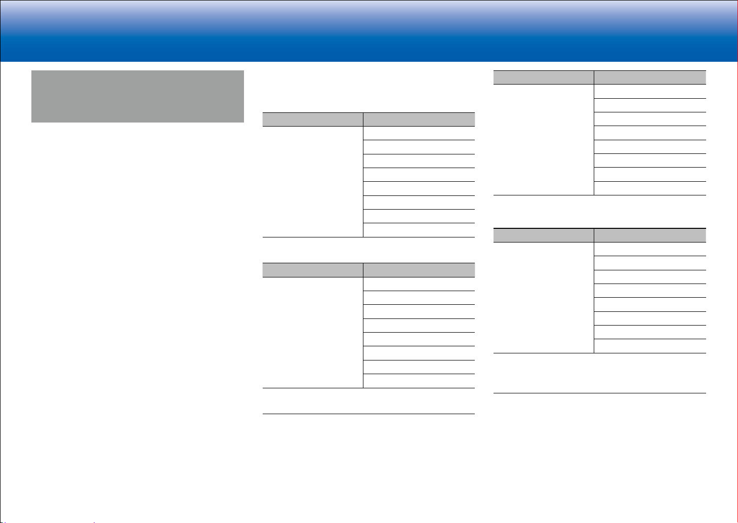
> Specifications > Advanced Setup > Listening Modes > Network Functions > Basic Manual
|Troubleshooting Supplementary Information, etc.
Selectable Listening Modes
You can select a variety of listening modes to suit the audio
format of the signal being input. Refer to the following for
the listening mode choices.
•
Listening modes available when headphones are
connected are: Mono, Direct, and Stereo.
■ Movie/TV button
This is a list of listening modes you can select according to
the audio format of the input signal.
Input Format Listening Mode
Analog Direct
Mono
Dolby Surround
DTS Neural:X
TV Logic
AllCh Stereo
Full Mono
T-D
1
Surround speakers or height speakers need to be installed.
2
A center speaker, surround speakers, or height speakers need to be
installed.
Input Format Listening Mode
PCM
Music files (except DSD/
Dolby TrueHD)
Direct
Mono
Dolby Surround
DTS Neural:X
TV Logic
AllCh Stereo
Full Mono
T-D
1
Surround speakers or height speakers need to be installed.
2
A center speaker, surround speakers, or height speakers need to be
installed.
1
2
2
1
2
2
Input Format Listening Mode
Multich PCM Direct
1
Multich
Dolby Surround
DTS Neural:X
TV Logic
AllCh Stereo
Full Mono
2
3
3
T-D
1
A center speaker or surround speakers need to be installed.
2
Surround speakers or height speakers need to be installed.
3
A center speaker, surround speakers, or height speakers need to be
installed.
Input Format Listening Mode
DSD Direct
1
2
DSD
Dolby Surround
DTS Neural:X
TV Logic
AllCh Stereo
Full Mono
3
4
4
T-D
1
Cannot be selected when the input format is monaural or 2 ch.
2
A center speaker or surround speakers need to be installed.
3
Surround speakers or height speakers need to be installed.
4
A center speaker, surround speakers, or height speakers need to be
installed.
43
Page 76

> Specifications > Advanced Setup > Listening Modes > Network Functions > Basic Manual
|Troubleshooting Supplementary Information, etc.
Input Format Listening Mode
Dolby Atmos
•
You can select the
Dolby Digital Plus or
Dolby TrueHD listening
modes if surround
back speakers or
height speakers are
not connected.
Direct
Dolby Atmos
TV Logic
AllCh Stereo
Full Mono
T-D
Input Format Listening Mode
Dolby D Direct
1
Dolby D
2
Dolby Surround
TV Logic
AllCh Stereo
Full Mono
3
4
4
T-D
1
Cannot be selected when the input format is 2 ch.
2
A center speaker or surround speakers need to be installed.
3
Surround speakers or height speakers need to be installed.
4
A center speaker, surround speakers, or height speakers need to be
installed.
Input Format Listening Mode
Dolby D+ Direct
1
Dolby D+
2
Dolby Surround
TV Logic
AllCh Stereo
Full Mono
3
4
4
T-D
1
Cannot be selected when the input format is 2 ch.
2
A center speaker or surround speakers need to be installed.
3
Surround speakers or height speakers need to be installed.
4
A center speaker, surround speakers, or height speakers need to be
installed.
Input Format Listening Mode
Dolby TrueHD Direct
1
Dolby TrueHD
2
Dolby Surround
TV Logic
AllCh Stereo
Full Mono
3
4
4
T-D
1
Cannot be selected when the input format is 2 ch.
2
A center speaker or surround speakers need to be installed.
3
Surround speakers or height speakers need to be installed.
4
A center speaker, surround speakers, or height speakers need to be
installed.
Input Format Listening Mode
DTS Direct
1
2
DTS
DTS Neural:X
TV Logic
AllCh Stereo
Full Mono
3
4
4
T-D
1
Cannot be selected when the input format is 2 ch.
2
A center speaker or surround speakers need to be installed.
3
Surround speakers or height speakers need to be installed.
4
A center speaker, surround speakers, or height speakers need to be
installed.
Input Format Listening Mode
DTS 96/24 Direct
1
DTS 96/24
2
DTS Neural:X
TV Logic
AllCh Stereo
Full Mono
3
4
4
T-D
1
Cannot be selected when the input format is 2 ch.
2
A center speaker or surround speakers need to be installed.
3
Surround speakers or height speakers need to be installed.
4
A center speaker, surround speakers, or height speakers need to be
installed.
44
Page 77

> Specifications > Advanced Setup > Listening Modes > Network Functions > Basic Manual
|Troubleshooting Supplementary Information, etc.
Input Format Listening Mode
DTS Express Direct
1
DTS Express
2
DTS Neural:X
TV Logic
AllCh Stereo
Full Mono
3
4
4
T-D
1
Cannot be selected when the input format is 2 ch.
2
A center speaker or surround speakers need to be installed.
3
Surround speakers or height speakers need to be installed.
4
A center speaker, surround speakers, or height speakers need to be
installed.
Input Format Listening Mode
DTS-HD HR Direct
1
DTS-HD HR
2
DTS Neural:X
TV Logic
AllCh Stereo
Full Mono
3
4
4
T-D
1
Cannot be selected when the input format is 2 ch.
2
A center speaker or surround speakers need to be installed.
3
Surround speakers or height speakers need to be installed.
4
A center speaker, surround speakers, or height speakers need to be
installed.
Input Format Listening Mode
DTS-HD MSTR Direct
1
DTS-HD MSTR
2
DTS Neural:X
TV Logic
AllCh Stereo
Full Mono
3
4
4
T-D
1
Cannot be selected when the input format is 2 ch.
2
A center speaker or surround speakers need to be installed.
3
Surround speakers or height speakers need to be installed.
4
A center speaker, surround speakers, or height speakers need to be
installed.
Input Format Listening Mode
DTS-ES Direct
1
DTS
ES Matrix
ES Discrete
2
2
DTS Neural:X
TV Logic
AllCh Stereo
Full Mono
3
4
4
T-D
1
This can only be selected when no surround back speaker is connected.
2
Surround back speakers need to be installed.
3
Surround speakers or height speakers need to be installed.
4
A center speaker, surround speakers, or height speakers need to be
installed.
Input Format Listening Mode
DTS:X Direct
DTS:X
TV Logic
AllCh Stereo
Full Mono
1
2
2
T-D
1
Surround speakers or height speakers need to be installed.
2
A center speaker, surround speakers, or height speakers need to be
installed.
45
Page 78

> Specifications > Advanced Setup > Listening Modes > Network Functions > Basic Manual
|Troubleshooting Supplementary Information, etc.
■ Music button
This is a list of listening modes you can select according to
the audio format of the input signal.
Input Format Listening Mode
Analog Direct
Stereo
Dolby Surround
DTS Neural:X
Orchestra
Unplugged
Studio-Mix
AllCh Stereo
Full Mono
1
Surround speakers or height speakers need to be installed.
2
A center speaker, surround speakers, or height speakers need to be
installed.
1
1
1
2
2
Input Format Listening Mode
PCM
Music files (except DSD/
Dolby TrueHD)
Direct
Stereo
Dolby Surround
DTS Neural:X
Orchestra
Unplugged
Studio-Mix
AllCh Stereo
Full Mono
1
Surround speakers or height speakers need to be installed.
2
A center speaker, surround speakers, or height speakers need to be
installed.
1
1
1
2
2
Input Format Listening Mode
Multich PCM Direct
Stereo
1
Multich
Dolby Surround
DTS Neural:X
Orchestra
Unplugged
Studio-Mix
AllCh Stereo
Full Mono
1
A center speaker or surround speakers need to be installed.
2
Surround speakers or height speakers need to be installed.
3
A center speaker, surround speakers, or height speakers need to be
installed.
2
2
2
3
3
Input Format Listening Mode
DSD Direct
Stereo
1
2
DSD
Dolby Surround
DTS Neural:X
Orchestra
Unplugged
Studio-Mix
AllCh Stereo
Full Mono
1
Cannot be selected when the input format is monaural or 2 ch.
2
A center speaker or surround speakers need to be installed.
3
Surround speakers or height speakers need to be installed.
4
A center speaker, surround speakers, or height speakers need to be
installed.
3
3
3
4
4
Input Format Listening Mode
Dolby Atmos
•
You can select the
Dolby Digital Plus or
Dolby TrueHD listening
modes if surround
back speakers or
height speakers are
not connected.
Direct
Stereo
Dolby Atmos
Orchestra
Unplugged
Studio-Mix
AllCh Stereo
Full Mono
46
Page 79

> Specifications > Advanced Setup > Listening Modes > Network Functions > Basic Manual
|Troubleshooting Supplementary Information, etc.
Input Format Listening Mode
Dolby D Direct
Stereo
1
Dolby D
2
Dolby Surround
Orchestra
Unplugged
Studio-Mix
AllCh Stereo
Full Mono
1
Cannot be selected when the input format is 2 ch.
2
A center speaker or surround speakers need to be installed.
3
Surround speakers or height speakers need to be installed.
4
A center speaker, surround speakers, or height speakers need to be
installed.
3
3
3
4
4
Input Format Listening Mode
Dolby D+ Direct
Stereo
1
Dolby D+
2
Dolby Surround
Orchestra
Unplugged
Studio-Mix
AllCh Stereo
Full Mono
1
Cannot be selected when the input format is 2 ch.
2
A center speaker or surround speakers need to be installed.
3
Surround speakers or height speakers need to be installed.
4
A center speaker, surround speakers, or height speakers need to be
installed.
3
3
3
4
4
Input Format Listening Mode
Dolby TrueHD Direct
Stereo
1
Dolby TrueHD
2
Dolby Surround
Orchestra
Unplugged
Studio-Mix
AllCh Stereo
Full Mono
1
Cannot be selected when the input format is 2 ch.
2
A center speaker or surround speakers need to be installed.
3
Surround speakers or height speakers need to be installed.
4
A center speaker, surround speakers, or height speakers need to be
installed.
3
3
3
4
4
Input Format Listening Mode
DTS Direct
Stereo
1
2
DTS
DTS Neural:X
Orchestra
Unplugged
Studio-Mix
AllCh Stereo
Full Mono
1
Cannot be selected when the input format is 2 ch.
2
A center speaker or surround speakers need to be installed.
3
Surround speakers or height speakers need to be installed.
4
A center speaker, surround speakers, or height speakers need to be
installed.
3
3
3
4
4
Input Format Listening Mode
DTS 96/24 Direct
Stereo
1
DTS 96/24
2
DTS Neural:X
Orchestra
Unplugged
Studio-Mix
AllCh Stereo
Full Mono
1
Cannot be selected when the input format is 2 ch.
2
A center speaker or surround speakers need to be installed.
3
Surround speakers or height speakers need to be installed.
4
A center speaker, surround speakers, or height speakers need to be
installed.
3
3
3
4
4
Input Format Listening Mode
DTS Express Direct
Stereo
1
DTS Express
2
DTS Neural:X
Orchestra
Unplugged
Studio-Mix
AllCh Stereo
Full Mono
1
Cannot be selected when the input format is 2 ch.
2
A center speaker or surround speakers need to be installed.
3
Surround speakers or height speakers need to be installed.
4
A center speaker, surround speakers, or height speakers need to be
installed.
3
3
3
4
4
47
Page 80

> Specifications > Advanced Setup > Listening Modes > Network Functions > Basic Manual
|Troubleshooting Supplementary Information, etc.
Input Format Listening Mode
DTS-HD HR Direct
Stereo
1
DTS-HD HR
2
DTS Neural:X
Orchestra
Unplugged
Studio-Mix
AllCh Stereo
Full Mono
1
Cannot be selected when the input format is 2 ch.
2
A center speaker or surround speakers need to be installed.
3
Surround speakers or height speakers need to be installed.
4
A center speaker, surround speakers, or height speakers need to be
installed.
3
3
3
4
4
Input Format Listening Mode
DTS-HD MSTR Direct
Stereo
1
DTS-HD MSTR
2
DTS Neural:X
Orchestra
Unplugged
Studio-Mix
AllCh Stereo
Full Mono
1
Cannot be selected when the input format is 2 ch.
2
A center speaker or surround speakers need to be installed.
3
Surround speakers or height speakers need to be installed.
4
A center speaker, surround speakers, or height speakers need to be
installed.
3
3
3
4
4
Input Format Listening Mode
DTS-ES Direct
Stereo
1
DTS
ES Matrix
ES Discrete
2
2
DTS Neural:X
Orchestra
Unplugged
Studio-Mix
AllCh Stereo
Full Mono
1
This can only be selected when no surround back speaker is connected.
2
Surround back speakers need to be installed.
3
Surround speakers or height speakers need to be installed.
4
A center speaker, surround speakers, or height speakers need to be
installed.
3
3
3
4
4
Input Format Listening Mode
DTS:X Direct
Stereo
DTS:X
Orchestra
Unplugged
Studio-Mix
AllCh Stereo
Full Mono
1
Surround speakers or height speakers need to be installed.
2
A center speaker, surround speakers, or height speakers need to be
installed.
1
1
1
2
2
48
Page 81
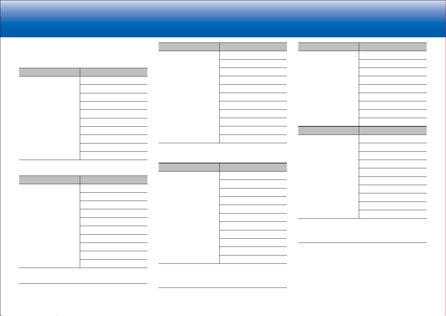
> Specifications > Advanced Setup > Listening Modes > Network Functions > Basic Manual
|Troubleshooting Supplementary Information, etc.
■ Game button
This is a list of listening modes you can select according to
the audio format of the input signal.
Input Format Listening Mode
Analog Direct
Dolby Surround
DTS Neural:X
Game-RPG
Game-Action
Game-Rock
Game-Sports
AllCh Stereo
Full Mono
T-D
1
Surround speakers or height speakers need to be installed.
2
A center speaker, surround speakers, or height speakers need to be
installed.
Input Format Listening Mode
PCM
Music files (except DSD/
Dolby TrueHD)
Direct
Dolby Surround
DTS Neural:X
Game-RPG
Game-Action
Game-Rock
Game-Sports
AllCh Stereo
Full Mono
T-D
1
Surround speakers or height speakers need to be installed.
2
A center speaker, surround speakers, or height speakers need to be
installed.
1
1
1
1
2
2
1
1
1
1
2
2
Input Format Listening Mode
Multich PCM Direct
1
Multich
Dolby Surround
DTS Neural:X
Game-RPG
Game-Action
Game-Rock
Game-Sports
AllCh Stereo
Full Mono
2
2
2
2
3
3
T-D
1
A center speaker or surround speakers need to be installed.
2
Surround speakers or height speakers need to be installed.
3
A center speaker, surround speakers, or height speakers need to be
installed.
Input Format Listening Mode
DSD Direct
1
2
DSD
Dolby Surround
DTS Neural:X
Game-RPG
Game-Action
Game-Rock
Game-Sports
AllCh Stereo
Full Mono
3
3
3
3
4
4
T-D
1
Cannot be selected when the input format is monaural or 2 ch.
2
A center speaker or surround speakers need to be installed.
3
Surround speakers or height speakers need to be installed.
4
A center speaker, surround speakers, or height speakers need to be
installed.
Input Format Listening Mode
Dolby Atmos
•
You can select the
Dolby Digital Plus or
Dolby TrueHD listening
modes if surround
back speakers or
height speakers are
not connected.
Direct
Dolby Atmos
Game-RPG
Game-Action
Game-Rock
Game-Sports
AllCh Stereo
Full Mono
T-D
Input Format Listening Mode
Dolby D Direct
1
Dolby D
2
Dolby Surround
Game-RPG
Game-Action
Game-Rock
Game-Sports
AllCh Stereo
Full Mono
3
3
3
3
4
4
T-D
1
Cannot be selected when the input format is 2 ch.
2
A center speaker or surround speakers need to be installed.
3
Surround speakers or height speakers need to be installed.
4
A center speaker, surround speakers, or height speakers need to be
installed.
49
Page 82

> Specifications > Advanced Setup > Listening Modes > Network Functions > Basic Manual
|Troubleshooting Supplementary Information, etc.
Input Format Listening Mode
Dolby D+ Direct
1
Dolby D+
2
Dolby Surround
Game-RPG
Game-Action
Game-Rock
Game-Sports
AllCh Stereo
Full Mono
3
3
3
3
4
4
T-D
1
Cannot be selected when the input format is 2 ch.
2
A center speaker or surround speakers need to be installed.
3
Surround speakers or height speakers need to be installed.
4
A center speaker, surround speakers, or height speakers need to be
installed.
Input Format Listening Mode
Dolby TrueHD Direct
1
Dolby TrueHD
2
Dolby Surround
Game-RPG
Game-Action
Game-Rock
Game-Sports
AllCh Stereo
Full Mono
3
3
3
3
4
4
T-D
1
Cannot be selected when the input format is 2 ch.
2
A center speaker or surround speakers need to be installed.
3
Surround speakers or height speakers need to be installed.
4
A center speaker, surround speakers, or height speakers need to be
installed.
Input Format Listening Mode
DTS Direct
1
2
DTS
DTS Neural:X
Game-RPG
Game-Action
Game-Rock
Game-Sports
AllCh Stereo
Full Mono
3
3
3
3
4
4
T-D
1
Cannot be selected when the input format is 2 ch.
2
A center speaker or surround speakers need to be installed.
3
Surround speakers or height speakers need to be installed.
4
A center speaker, surround speakers, or height speakers need to be
installed.
Input Format Listening Mode
DTS 96/24 Direct
1
DTS 96/24
2
DTS Neural:X
Game-RPG
Game-Action
Game-Rock
Game-Sports
AllCh Stereo
Full Mono
3
3
3
3
4
4
T-D
1
Cannot be selected when the input format is 2 ch.
2
A center speaker or surround speakers need to be installed.
3
Surround speakers or height speakers need to be installed.
4
A center speaker, surround speakers, or height speakers need to be
installed.
Input Format Listening Mode
DTS Express Direct
1
DTS Express
2
DTS Neural:X
Game-RPG
Game-Action
Game-Rock
Game-Sports
AllCh Stereo
Full Mono
3
3
3
3
4
4
T-D
1
Cannot be selected when the input format is 2 ch.
2
A center speaker or surround speakers need to be installed.
3
Surround speakers or height speakers need to be installed.
4
A center speaker, surround speakers, or height speakers need to be
installed.
Input Format Listening Mode
DTS-HD HR Direct
1
DTS-HD HR
2
DTS Neural:X
Game-RPG
Game-Action
Game-Rock
Game-Sports
AllCh Stereo
Full Mono
3
3
3
3
4
4
T-D
1
Cannot be selected when the input format is 2 ch.
2
A center speaker or surround speakers need to be installed.
3
Surround speakers or height speakers need to be installed.
4
A center speaker, surround speakers, or height speakers need to be
installed.
50
Page 83
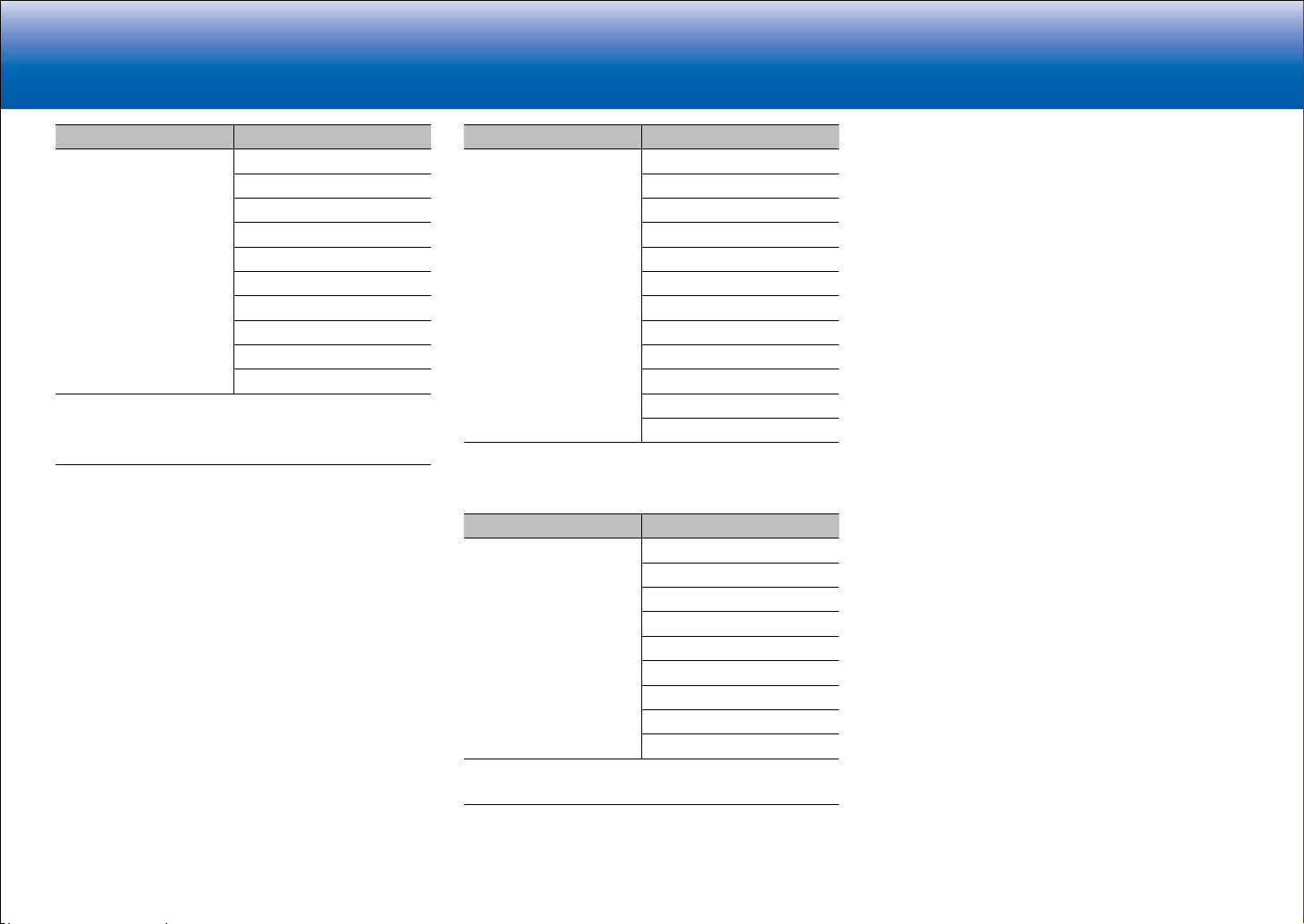
> Specifications > Advanced Setup > Listening Modes > Network Functions > Basic Manual
|Troubleshooting Supplementary Information, etc.
Input Format Listening Mode
DTS-HD MSTR Direct
1
DTS-HD MSTR
2
DTS Neural:X
Game-RPG
Game-Action
Game-Rock
Game-Sports
AllCh Stereo
Full Mono
3
3
3
3
4
4
T-D
1
Cannot be selected when the input format is 2 ch.
2
A center speaker or surround speakers need to be installed.
3
Surround speakers or height speakers need to be installed.
4
A center speaker, surround speakers, or height speakers need to be
installed.
Input Format Listening Mode
DTS-ES Direct
1
DTS
ES Matrix
ES Discrete
2
2
DTS Neural:X
Game-RPG
Game-Action
Game-Rock
Game-Sports
AllCh Stereo
Full Mono
3
3
3
3
4
4
T-D
1
This can only be selected when no surround back speaker is connected.
2
Surround back speakers need to be installed.
3
Surround speakers or height speakers need to be installed.
4
A center speaker, surround speakers, or height speakers need to be
installed.
Input Format Listening Mode
DTS:X Direct
DTS:X
Game-RPG
Game-Action
Game-Rock
Game-Sports
AllCh Stereo
Full Mono
1
1
1
1
2
2
T-D
1
Surround speakers or height speakers need to be installed.
2
A center speaker, surround speakers, or height speakers need to be
installed.
51
Page 84

> Specifications > Advanced Setup > Listening Modes > Network Functions
> Basic Manual
|Troubleshooting Supplementary Information, etc.
LINKS
Internet Radio
You can use internet radio services such as TuneIn Radio,
Pandora, Deezer, and TIDAL by connecting this unit to a
network that has an internet connection.
•
Depending on the internet radio service, the user may
need to register from their computer first. Refer to the
websites for each of the services for details about them.
•
Functionality may be introduced by firmware updates
and service providers may cease services, meaning
that some network services and content may become
unavailable in the future.
■ Playing Back
1. Switch the input on the TV to that assigned to the unit.
2. Press NET on the remote controller to display a list of
Network Functions on the TV.
■ Internet radio service menus
You can register certain stations as your favorites or delete
stations you have registered from your favorites. The menu
displayed depends on the service currently selected.
Menu icons
screen while playing a station. When just this icon is
displayed, you can display the menu on the screen just
by pressing Enter on the remote controller. When multiple
icons are displayed, select an icon with the cursors of
the remote controller and press Enter.
are displayed at the bottom right of the
■ Regarding the TuneIn Radio Account
Creating an account on the TuneIn Radio website
(tunein.com) and logging in it from the unit allows you
to automatically add your favorite radio stations and
programs to your "My Presets" on the unit as you follow
them on the website. "My Presets" are displayed in the
level under TuneIn Radio.
To display a radio station registered in "My Presets", you
must log into TuneIn Radio from the unit. To log in, select
"Login" - "I have a TuneIn account" in the "TuneIn Radio"
top list on the unit, and then enter your user name and
password.
•
If you select "Login" on this unit, you can use the
displayed registration code to associate this device on
the My Page section of the TuneIn Radio website so
that you can login to "Login" - "Login with a registration
code" without having to enter your user name and
password.
3. Select the internet radio service you want with the
cursors of the remote controller and press Enter to
confirm your selection.
4. Follow the on-screen instructions, using the cursors
on the remote controller to select radio stations and
programs, then press Enter to play.
•
To return to the previous screen, press
52
.
Page 85

> Specifications > Advanced Setup > Listening Modes > Network Functions
DevicesAvailable
Device
■ Notes for using multi-zone (for compatible
models only)
Spotify
Spotify Connect play is possible by connecting this unit to
the same network as a smart phone or tablet.
•
To play Spotify Connect, you need to install the Spotify
application on your smartphone or tablet. You also need
to create a Spotify premium account.
•
Refer to the following for Spotify settings:
www.spotify.com/connect/
■ Playing Back
1. Connect the smartphone to the access point that this
unit is connected to.
2. Start the Spotify app.
3. Play the track in the Spotify app, then after switching to
the screen for controlling play, tap "Devices Available" at
the bottom of the screen.
•
To enjoy Spotify music in a separate room, manually
select "NET" as the input of the separate room. After
doing that, select this unit with the Spotify app.
•
Volume adjustment with the Spotify app is possible only
for speakers connected to the ZONE speaker terminals
or when the volume of the audio device in the other
room is configured so that its volume can be adjusted
on this unit. Adjust the volume on the audio equipment
in the other room in any other case.
•
To enjoy Spotify music in the main room after playing
it in a separate room, select "NET" as the input of the
main room.
> Basic Manual
|Troubleshooting Supplementary Information, etc.
4. Select this unit.
5. This unit turns on automatically and the input selector
changes to NET and streaming of Spotify starts.
•
If "6. Hardware" - "Power Management" - "Network
Standby" is set to "Off" in the Setup menu, manually
turn the unit on and then press NET on the remote
controller.
53
Page 86
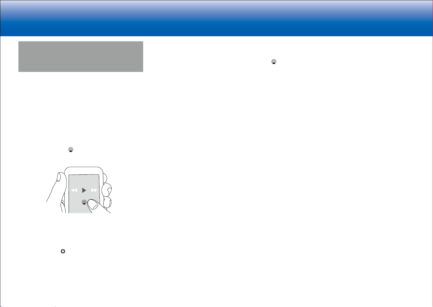
> Specifications > Advanced Setup > Listening Modes > Network Functions
You can also play the music files on a computer with
AirPlay
You can wirelessly enjoy the music files on an iPhone
iPod touch®, or iPad® connected to the same access point
as this unit.
•
Update the OS version on your iOS device to the latest
version.
•
There may be some differences in the operations
screens and how operations are performed on the iOS
device depending on the iOS version. For details, see
the operating instructions for the iOS device.
1. Connect the iOS device to the access point.
2. Press NET.
3. Tap the AirPlay icon
app on the iOS device and select this unit from the list
of devices displayed.
in the play screen of the music
®
®
,
iTunes (Ver. 10.2 or later). Before operation, make sure
this unit and the PC are connected to the same network,
then press NET on this unit. Next, click the AirPlay icon
in iTunes, select this unit from the list of devices displayed,
and start play of a music file.
> Basic Manual
|Troubleshooting Supplementary Information, etc.
4. Play the music files on the iOS device.
•
The default status is for the Network Standby feature to
be on, so when you do steps 3 and 4 above, this unit
automatically comes on and input switches to "NET".
To reduce the amount of power consumed in standby
mode, press the
then in the Setup menu displayed set "6. Hardware" "Power Management" - "Network Standby" to "Off".
•
Due to the characteristics of AirPlay wireless
technology, the sound produced on this unit may slightly
be behind the sound played on the AirPlay-enabled
device.
button on the remote controller,
54
Page 87

> Specifications > Advanced Setup > Listening Modes > Network Functions
> Basic Manual
|Troubleshooting Supplementary Information, etc.
Music Server
Overview
Streaming play of music files stored on PCs or NAS
devices connected to the same network as this unit is
supported.
•
The network servers this unit is compatible with
are those PCs with players installed that have the
server functionality of Windows Media
12, or NAS that are compatible with home network
functionality. You may need to make some settings in
advance to use Windows MediaR Player 11 or 12. Note
that with PCs, only music files registered in the library of
Windows MediaR Player can be played.
R
Player 11 or
Configuring the Windows MediaR Player
R
■ Windows Media
1. Turn on your PC and start Windows MediaR Player 11.
2. In the "Library" menu, select "Media Sharing" to display
a dialog box.
3. Select the "Share my media" check box, and then click
"OK" to display the compatible devices.
4. Select this unit, and then click "Allow".
•
When it is clicked, the corresponding icon is
checked.
5. Click "OK" to close the dialog.
•
Depending of the version of Windows Media
there may be differences in the names of items you can
select.
Player 11
R
Player,
■ Windows MediaR Player 12
1. Turn on your PC and start Windows MediaR Player 12.
2. In the "Stream" menu, select "Turn on media streaming"
to display a dialog box.
•
If media streaming is already turned on, select
"More streaming options..." in the "Stream" menu to
list players in the network, and then go to step 4.
3. Click "Turn on media streaming" to list players in the
network.
4. Select this unit in "Media streaming options" and check
that it is set to "Allow".
5. Click "OK" to close the dialog.
•
Depending of the version of Windows Media
there may be differences in the names of items you can
select.
R
Player,
Play
1. Start the server (Windows MediaR Player 11, Windows
MediaR Player 12, or NAS device) containing the music
files to play.
2. Make sure that the PCs and/or NASs are properly
connected to the same network as this unit.
3. Press NET on the remote controller to display the
network service list screen.
•
If the "NET" indicator flashes in the display, the unit
is not properly connected to the network. Check the
connection.
4. With the cursors on the remote controller, select "Music
Server", and then press Enter.
5. Select the target server with the cursors on the remote
controller and press Enter to display the items list
screen.
•
The unit cannot access pictures and videos stored
on servers.
•
Contents stored on the server may not be displayed
depending on the server sharing settings.
6. With the cursors on the remote controller, select
the music file to play, and then press Enter to start
playback.
•
If "No Item." is displayed, check whether the network
is properly connected.
•
To return to the previous screen, press
.
•
For music files on a server, there can be up to 20,000
tracks per folder, and folders may be nested up to 16
55
Page 88

> Specifications > Advanced Setup > Listening Modes > Network Functions
> Basic Manual
|Troubleshooting Supplementary Information, etc.
levels deep.
•
Depending on the media server, the unit may not
recognize it, or may not be able to play its music files.
Controlling Remote Playback from a PC
You can use this unit to play music files stored on your PC
by operating the PC inside your home network. The unit
supports remote playback with Windows MediaR Player 12.
To use the remote playback function with Windows MediaR
Player 12, it must be configured in advance.
■ Setting PC
1. Turn on your PC and start Windows MediaR Player 12.
2. In the "Stream" menu, select "Turn on media streaming"
to display a dialog box.
•
If media streaming is already turned on, select
"More streaming options..." in the "Stream" menu to
list players in the network, and then go to step 4.
3. Click "Turn on media streaming" to list players in the
network.
4. Select this unit in "Media streaming options" and check
that it is set to "Allow".
5. Click "OK" to close the dialog box.
6. Open the "Stream" menu and check that "Allow remote
control of my Player..." is checked.
•
Depending of the version of Windows Media
there may be differences in the names of items you can
select.
R
Player,
to", and then select this unit. If your PC is running
on Windows
R
10, click "Cast to Device", and select
this unit. Operations during remote playback are
possible from the "Play to" window on the PC. The
playback screen is displayed on the TV connected
to the HDMI output of the unit.
5. Adjust the volume using the volume bar on the "Play to"
window.
•
Sometimes, the volume displayed on the remote
playback window may differ from that appeared on
the display of the unit.
•
When the volume is adjusted from the unit, the value
is not reflected in the "Play to" window.
•
This unit cannot play music files remotely in the
following conditions.
−
It is using a network service.
−
It is playing a music file on a USB storage
device.
•
Depending of the version of Windows Media
R
Player,
there may be differences in the names of items you can
select.
56
■ Remote playback
1. Turn on the power of the unit.
2. Turn on your PC and start Windows Media
3. Select and right-click the music file to play with
Windows Media
•
To remotely play a music file on another server,
R
Player 12.
open the target server from "Other Libraries" and
select the music file to play.
4. Select this unit in "Play to" to open the "Play to" window
of Windows Media
R
Player 12 and start playback on the
unit.
•
If your PC is running on WindowsR 8.1, click "Play
R
Player 12.
Page 89
> Specifications > Advanced Setup > Listening Modes > Network Functions
Supplementary information for
player functions
Due to firmware (the software for the system) updates
after you make your purchase or firmware changes during
production of the product, there may be additions or
changes to the features available compared to what is in
the instruction manual.
For information about player functions that have been
added or changed, see the following references. Refer
to "Supplementary Information, etc." - "Supplementary
Information" for information about changes to settings, etc.,
other than player functions.
Supplementary information for player functions
>>> Click here <<<
> Basic Manual
|Troubleshooting Supplementary Information, etc.
57
Page 90

> Specifications > Advanced Setup > Listening Modes > Network Functions
> Basic Manual
|Troubleshooting Supplementary Information, etc.
LINKS
Troubleshooting
Before starting the procedure
Problems may be solved by simply turning the power on/
off or disconnecting/connecting the power cord, which
is easier than working on the connection, setting and
operating procedure. Try the simple measures on both the
unit and the connected device. If the problem is that the
video or audio is not output or the HDMI linked operation
does not work, disconnecting/connecting the HDMI cable
may solve it. When reconnecting, be careful not to wind
the HDMI cable since if wound the HDMI cable may not
fit well. After reconnecting, turn off and on the unit and the
connected device.
•
This unit contains a microPC for signal processing
and control functions. In very rare situations, severe
interference, noise from an external source, or static
electricity may cause it to lockup. In the unlikely event
that this happens, unplug the power cord from the wall
outlet, wait at least 5 seconds, and then plug it back in.
•
Our company is not responsible for reparations for
damages (such as CD rental fees) due to unsuccessful
recordings caused by the unit's malfunction. Before you
record important data, make sure that the material will
be recorded correctly.
When the unit is operating erratically
■ Try restarting the unit
Restarting the unit may help it operate more smoothly. To
restart the unit, turn it to standby, and then press
Standby on the main unit for at least 5 seconds. (The unit's
settings will be maintained.) If there is no improvement
even after the unit is restarted, try disconnecting and
reconnecting the power cords of the unit and connected
equipment.
58
On/
■ Resetting the unit (this resets the unit settings to
the default)
If restarting the unit doesn't fix the problem, resetting the
unit to the status at the time of shipment may solve the
problem. If you reset the unit status, your preferences
will be reset to the defaults. Note them down before the
operation below.
1. While pressing the CBL/SAT input selector button on
the main unit, press
2. "Clear" appears on the display and the unit returns to
standby. Do not unplug the power cord until "Clear"
disappears from the display.
To reset the remote controller, while holding down Mode,
press
seconds or more).
until the remote indicator flashes twice (3
On/Standby.
Power
■ Cannot turn on the unit
•
Make sure that the power cord is properly plugged into
the wall outlet.
•
Unplug the power cord from the wall outlet, wait 5
seconds or more, then plug it in again.
■ The unit turns off unexpectedly
•
The unit automatically switches to standby when the
"Hardware" - "Power Management" - "Auto Standby"
setting in the Setup menu functions.
•
The protective circuit function may have been activated.
If this has occurred, "AMP Diag Mode" appears on the
display when the unit is turned on again, and the unit
enters diagnostic mode. If the results of the diagnosis is
that there is no problem, the "AMP Diag Mode" display
disappears and you can use the unit normally again. If
"CHECK SP WIRE" appears on the display, the speaker
cables may be short-circuited. Make sure bare speaker
wires are not touching each other or the back panel of
the unit, then turn the unit on again. If "NG" is displayed,
immediately unplug the power cord from the wall outlet
and contact your dealer.
•
The protective circuit function may have been activated
because the temperature of the unit rose abnormally.
If this happens, then the power will continue to turn off
after you have turned the unit on again. Make sure the
unit has plenty of space for ventilation around it, wait for
the unit to cool down sufficiently, and then try turning it
on again.
WARNING: If smoke, smell or abnormal noise is produced
by the unit, unplug the power cord from the wall outlet
immediately and contact the dealer or our company's
support.
Page 91
> Specifications > Advanced Setup > Listening Modes > Network Functions
> Basic Manual
|Troubleshooting Supplementary Information, etc.
Audio
•
Make sure that the speaker setup microphone is not still
connected.
•
Confirm that the connection between the output jack on
the device and the input jack on this unit is correct.
•
Make sure that none of the connecting cables are bent,
twisted, or damaged.
•
If the MUTE indicator on the display flashes, press
on the remote controller to cancel muting.
•
While headphones are connected to the Phones jack,
no sound is output from the speakers.
•
When "Source" - "Audio Select" - "PCM Fixed Mode" in
the Setup menu is set to "On", no sound is played when
signals other than PCM are input. Change the setting to
Off.
Check the following if the above does not fix the problem:
■ There is no sound from the TV
•
Change the input selector on this unit to the position of
the terminal to which the TV is connected.
•
If the TV doesn't support the ARC function, along with
connection by HDMI, connect the TV and this unit using
a digital optical cable, digital coaxial cable, or analog
audio cable.
■ No sound from a connected player
•
Change the input selector on this unit to the position of
the terminal to which the player is connected.
•
Check the digital audio output setting on the connected
component. On some game consoles, such as those
that support DVD, the default setting is off.
•
With some DVD-Video discs, you need to select an
audio output format from a menu.
■ A speaker produces no sound
•
Make sure that the polarity of the speaker cables (+/-)
is correct, and that no bare wires are in contact with the
metal part of speaker terminals.
•
Make sure that the speaker cables are not shorting.
•
Check in "Connect the Speakers" in the Basic Manual
that the speaker connections have been made correctly.
Settings for the speaker connection environment need
to be made in "AccuEQ Room Calibration" in Initial
Setup. Check in "Initial Setup" in the Basic Manual.
•
Depending on the source and current listening mode,
not much sound may be produced. Select another
listening mode to see if sound is output.
•
If you are installing surround back speakers (for
compatible models only), surround speakers are
required.
•
A maximum of 5.1 ch playback is possible when BiAmping connection is used (for compatible models
only). Further, make sure you remove the jumper bar on
the speakers when using Bi-Amping connection.
■ The subwoofer produces no sound
If the setting of the front speakers is "Full Band" and during
2ch input such as from the TV or music, the low range
elements will be output from the front speakers rather than
from the subwoofer. If you would rather output from the
subwoofer, make one of the following settings.
1. Change the front speakers settings to a setting other
than "Full Band" for the crossover frequency value.
The range below the frequency you specify will
be output from the subwoofer rather than the front
speakers. We do not recommend changing this if your
front speakers have good low range reproduction
capabilities.
2. Change "Double Bass" to "On".
The low range elements will be output from both the
front speakers and the subwoofer. This may mean that
there is too much bass. Do not change if this happens,
or choose option 1.
•
Refer to "Setup Menu" - "2. Speaker" - "Crossover" in
the Advanced Manual for details.
•
When you play source material that contains no
information in the LFE channel, the subwoofer produces
no sound.
■ Noise can be heard
•
Using cable ties to bundle analog audio cables, power
cords, speaker cables, etc. may degrade the audio
performance. Do not bundle cords.
•
An audio cable may be picking up interference. Try
repositioning your cables.
■ The beginning of audio received by an HDMI IN
cannot be heard
•
Since it takes longer to identify the format of an HDMI
signal than it does for other digital audio signals, audio
output may not start immediately.
■ Sound suddenly reduces
•
When the temperature inside the unit exceeds a certain
temperature for extended periods, the volume may be
reduced automatically to protect the circuits.
59
Page 92

> Specifications > Advanced Setup > Listening Modes > Network Functions
> Basic Manual
|Troubleshooting Supplementary Information, etc.
Listening Modes
•
To enjoy digital surround playback, such as Dolby
Digital, the audio signals need to pass through a
connection via HDMI cable, digital coaxial cable, or
digital optical cable. Audio output should be set to
bitstream output on the connected Blu-ray Disc player
or other device.
•
Press
switch the display of the main unit to check the input
format.
Check the following if the above does not fix the problem:
■ Cannot select a desired listening mode
•
Depending on the connecting status of the speaker,
some listening modes may not be selected. Check in
"Selectable Listening Modes" in "Listening Modes" in
the Advanced Manual.
■ There is no sound with Dolby TrueHD, Dolby Atmos,
and DTS-HD Master Audio (for compatible models
only)
•
You need to connect surround back speakers or height
speakers to enjoy Dolby Atmos. Furthermore, Dolby
Atmos can only be enjoyed when the input signals are
Dolby Atmos.
•
If you cannot output formats such as Dolby TrueHD,
Dolby Atmos, or DTS-HD Master Audio according to the
format of the source, in the Blu-ray Disc player settings
try setting "BD video supplementary sound" (or reencode, secondary sound, video additional audio, etc.)
to "Off". Change the listening mode for each source
after changing the setting to confirm.
■ About DTS signals
•
With media that switches suddenly from DTS to PCM,
PCM playback may not start immediately. In such
cases, you should stop your player for about 3 seconds
and then resume playback.
•
With some CD and LD players, you will not be able
to playback DTS material properly even though your
player is connected to a digital input on the unit. This is
usually because the DTS bitstream has been processed
on the remote controller several times to
60
(e.g., output level, sampling rate, or frequency response
changed) and the unit does not recognize it as a
genuine DTS signal. In such cases, you may hear
noise.
•
Playing DTS program material, using the pause or skip
function on your player may produce a short audible
noise. This is not a malfunction.
Video
•
Confirm that the connection between the output jack on
the device and the input jack on this unit is correct.
•
Make sure that none of the connecting cables are bent,
twisted, or damaged.
•
When the TV image is blurry or unclear, power code or
connection cables of the unit may have interfered. In
that case, keep distance between TV antenna cable and
cables of the unit.
•
Make sure the switching of input screens is proper at
the monitor side such as a TV.
Check the following if the above does not fix the problem:
■ There is no video
•
Change the input selector on this unit to the position of
the terminal to which the player is connected.
■ There is no picture from a source connected to an
HDMI IN terminal.
•
To display video from the connected player on the
TV while the unit is in standby, you need to enable
"Hardware" - "HDMI" - "HDMI Standby Through" in the
Setup menu. Refer to "Setup Menu" - "6. Hardware"
- "■ 1. HDMI" in "Advanced Setup" in the Advanced
Manual for information about HDMI Standby Through.
•
To output video to a TV connected to the HDMI OUT
SUB jack (for compatible models only), in the "Quick
Menu" displayed when Q is pressed on the remote
controller, select the HDMI OUT jack for output in
"Other" - "HDMI Out".
•
Check if "Resolution Error" is displayed on the main
unit display when video input via HDMI IN jack is not
displayed. In this case, the TV does not support the
resolution of the video input from the player. Change the
setting on the player.
•
Reliable operation with an HDMI-DVI adapter is not
guaranteed. In addition, video signals from a PC are not
supported.
■ Images flicker
•
It is possible that the resolution of the player is not
compatible with the TV's resolution. If you have
Page 93

> Specifications > Advanced Setup > Listening Modes > Network Functions
> Basic Manual
|Troubleshooting Supplementary Information, etc.
connected the player to this unit with an HDMI cable, try
changing the output resolution on the player. There also
may be an improvement if you change the screen mode
on the TV.
■ Video and audio are out of synch
•
Video may be delayed relative to audio depending on
the settings and connections with your television. To
adjust, press Q on the remote controller, and adjust in
"Other" - "A/V Sync" in the "Quick Menu".
Linked operation
■ There is no linked operation with CEC compliant
devices, such as a TV.
•
In the Setup menu of the unit, set "Hardware" - "HDMI" "HDMI CEC" to "On".
•
It is also necessary to set HDMI linking on the CEC
compliant device. Check the instruction manual.
Tuner
■ Radio reception is poor or there is a lot of noise.
•
Re-check the antenna connection.
•
Relocate your antenna.
•
Move the unit away from your TV or PC.
•
Passing cars and airplanes can cause interference.
•
Concrete walls weaken radio signals.
•
Listen to the station in mono.
•
When listening to an AM station, operating the remote
controller may cause noise.
•
FM reception may become clearer if you use the
antenna jack on the wall used for the TV.
BLUETOOTH function (for compatible models
only)
•
Try plugging/unplugging the power of the unit and try
turning on/off the BLUETOOTH wireless technology
enabled device. Re-startup of the BLUETOOTH
wireless technology enabled device may be effective.
•
The BLUETOOTH wireless technology enabled devices
must support the A2DP profile.
•
Near components such as microwave oven or cordless
phone, which use the radio wave in the 2.4 GHz range,
a radio wave interference may occur, which disables the
use of this unit.
•
If there is a metallic object near the unit, BLUETOOTH
connection may not be possible as the metal can effect
on the radio waves.
Check the following if the above does not fix the problem:
■ Cannot connect with this unit
•
Check that the BLUETOOTH function of the
BLUETOOTH wireless technology enabled device is
enabled.
■ Music playback is unavailable on the unit even after
successful BLUETOOTH connection
•
When the audio volume of your BLUETOOTH wireless
technology enabled device is set low, the playback of
audio may be unavailable. Volume up the BLUETOOTH
wireless technology enabled device.
•
Depending on the BLUETOOTH wireless technology
enabled device, Send/Receive selector switch may be
provided. Select Send mode.
•
Depending on the characteristics or specifications of
your BLUETOOTH wireless technology enabled device,
playback on the unit is not guaranteed.
■ Sound is interrupted
•
Problem may be occurring at the BLUETOOTH wireless
technology enabled device. Check the information on
the internet.
■ The audio quality is poor after connection with a
BLUETOOTH wireless technology enabled device
•
The BLUETOOTH reception is poor. Move the
61
Page 94

> Specifications > Advanced Setup > Listening Modes > Network Functions
> Basic Manual
|Troubleshooting Supplementary Information, etc.
BLUETOOTH wireless technology enabled device
closer to the unit or remove any obstacle between the
BLUETOOTH wireless technology enabled device and
this unit.
62
Network function
•
If you cannot select a network service, it will become
selectable when the network function is started. It may
take about a minute to start up.
•
When NET is blinking, this unit is not properly
connected to the home network.
•
Try plugging/unplugging the power supply of this unit
and the router, and try rebooting the router.
•
If the desired wireless LAN router is not in the access
point list, it may be set to hide SSID or the ANY
connection may be off. Change the setting and try
again. (for compatible models only)
Check the following if the above does not fix the problem:
■ Cannot access the Internet radio
•
Certain network service or contents available through
the unit may not be accessible in case the service
provider terminates its service.
•
Make sure that your modem and router are properly
connected, and make sure they are both turned on.
•
Make sure that the LAN side port on the router is
properly connected to this unit.
•
Make sure that connecting to Internet from other
components is possible. If connecting is not possible,
turn off all components connected to the network, wait
for a while, and then turn on the components again.
•
If a specific radio station is unavailable for listening, make
sure the registered URL is correct, or whether the format
distributed from the radio station is supported by this unit.
•
Depending on ISP, setting the proxy server is
necessary.
•
Make sure that the used router and/or modem is
supported by your ISP.
■ Cannot access the network server
•
This unit needs to be connected to the same router as
the network server.
•
This unit is compatible with Windows Media
or 12 network servers or NAS that are compatible with
home network functionality.
•
You may need to make some settings on Windows
MediaR Player. Check in "Music Server" in "Network
R
Player 11
Functions" in the Advanced Manual.
•
When using a PC, only music files registered in the
Windows MediaR Player library can be played.
■ Playback stops while listening to music files on the
network server
•
Make sure the network server is compatible with this
unit.
•
When the PC is serving as the network server, try
quitting any application software other than the server
software (Windows Media
•
If the PC is downloading or copying large files, the
playback may be interrupted.
R
Player 12, etc.).
USB storage device
■ USB storage device is not displayed
•
Check whether the USB storage device or USB cable is
correctly inserted to the USB port of the unit.
•
Disconnect the USB storage device from the unit, and
then try reconnecting.
•
Performance of the hard disk that receive power from
the USB port of the unit is not guaranteed.
•
Depending on the type of format, the playback may
not be performed normally. Check the type of the file
formats that is supported.
•
USB storage devices with security functions may not be
played.
Page 95

> Specifications > Advanced Setup > Listening Modes > Network Functions
> Basic Manual
|Troubleshooting Supplementary Information, etc.
Wireless LAN Network (for compatible models
only)
•
Try plugging/unplugging the power supply of wireless
LAN router and the unit, check the wireless LAN router
power-on status, and try reboot of the wireless LAN
router.
Check the following if the above does not fix the problem:
■ Cannot access wireless LAN network
•
The wireless LAN router setting may be switched to
Manual. Return the setting to Auto.
•
Try the manual set-up. The connection may succeed.
•
When the wireless LAN router setting is at stealth mode
(mode to hide the SSID key) or when ANY connection
is off, the SSID is not displayed. Change the setting and
try again.
•
Check that the setting of SSID and encryption (WEP,
etc.) is correct. Make sure the network settings of the
unit is properly set.
•
Connection to an SSID that includes multi-byte
characters is not supported. Name the SSID of the
wireless LAN router using single-byte alphanumeric
characters only and try again.
■ Connected to an SSID different to the SSID selected
•
Some wireless LAN routers allow you to set multiple
SSIDs for one unit. If you use the automatic setting
button on such a router, you may end up connecting
with a different SSID from the SSID you wanted to
connect to. Use the connection method requiring you to
enter a password if this happens.
■ Playback is interrupted and communication does
not work
•
You may not receive radio waves due to bad radio wave
conditions. Shorten the distance from the wireless LAN
access point or remove obstacles to improve visibility,
and try again. Place the unit away from microwave
ovens or other access points. It is recommended to
place the wireless LAN router (access point) and the
unit in the same room.
•
If there is a metallic object near the unit, wireless LAN
connection may not be possible as the metal can effect
on the radio wave.
•
When other wireless LAN devices are used near the
unit, several issues such as interrupted playback
and communication may occur. You can avoid these
issues by changing the channel of your wireless LAN
router. For instructions on changing channels, see the
instruction manual provided with your wireless LAN
router.
•
There may not be enough bandwidth available in
wireless LAN. Connect using an Ethernet cable.
Multi-zone function (for compatible models only)
■ Cannot ZONE output audio of external AV
component
•
Depending on the model, input by HDMI cable may
not be supported. Check in "Multi-zone Connection"
in the Basic Manual, and if input by HDMI cable is not
supported, connect using a cable that is supported.
•
The audio from externally connected AV components
can only be output when the audio is analog or 2ch
PCM audio signals. If you have connected the AV
component to this unit with a digital optical/coaxial
cable, the audio output of the AV component needs to
be set to PCM.
■ Others
•
Settings are required in Initial Setup, "Multi Zone Setup"
to use the multi-zone feature. Check in "Initial Setup" in
the Basic Manual.
•
If the audio signal is from the NET input selector, zone
output is not possible for DSD and Dolby TrueHD audio
signals.
Remote Controller
•
Make sure that the batteries are installed with the
correct polarity.
•
Install new batteries. Do not mix different types of
batteries, or old and new batteries.
•
Make sure that the unit is not subjected to direct
sunshine or inverter-type fluorescent lights. Relocate if
necessary.
•
If the unit is installed in a rack or cabinet with coloredglass doors or if the doors are closed, the remote
controller may not work reliably.
•
After operating the Multi-zone function (for compatible
models only), the remote controller may have switched
to the mode for operating ZONE output audio. Check
"Multi-zone" in "Playback" in the Basic Manual to switch
the remote controller back to the mode for operating in
the main room.
Display
■ The display doesn't light
•
The display may go dim while the Dimmer is working,
and may also turn off (for compatible models only).
Press Dimmer button and change the brightness level
of the display.
Others
■ Strange noises can be heard from the unit
•
If you have connected another unit to the same wall
outlet as this unit, this noise may be an effect from the
other unit. If the symptoms improve by unplugging the
power cord of the other unit, use different wall outlets for
this unit and the other unit.
■ When performing AccuEQ Room Calibration, the
message "Noise Error" appears
•
This can be caused by a malfunction in your speaker
unit. Check if the speakers produce normal sounds.
■ The results of AccuEQ Room Calibration give a
different distance to the speakers than the actual
distance
•
There may be some discrepancies in the results
depending on the speakers you are using. If this is the
case, make the settings in "2. Speaker" - "Distance" in
the Setup menu.
63
Page 96

> Specifications > Advanced Setup > Listening Modes > Network Functions
> Basic Manual
|Troubleshooting Supplementary Information, etc.
Information about products with Wi-Fi/
BLUETOOTH features (for compatible models
only)
■ Radio Wave Caution
Products with Wi-Fi/BLUETOOTH use radio waves in the
2.4 GHz and 5 GHz frequency bands.
There are nations and regions where the use of particular
5 GHz bands are prohibited outdoors, so do not use these
products outside.
2.4 GHz radio waves are used by a variety of devices, as
shown in lists 1 and 2 below.
1. Devices which use a 2.4 GHz radio wave frequency
•
Cordless phones
•
Cordless facsimiles
•
Microwave ovens
•
Wireless LAN devices (IEEE802.11b/g/n)
•
Wireless AV equipment
•
Wireless controllers for game systems
•
Microwave oven-based health aids
•
Video transmitter
•
Specific type of external monitor and LCD display
2. Less common devices which use a 2.4 GHz radio wave
frequency
•
Anti-theft systems
•
Amateur radio stations (HAM)
•
Warehouse logistic management systems
•
Discrimination systems for train or emergency
vehicles
If these devices and the AV receiver are used at the same
time, the audio may be undesirably stopped or disturbed
due to a radio wave interference.
Suggestions for improvement
•
Switch off the devices which emit the radio wave.
•
Place the interfering devices away from the AV
receiver.
•
The AV receiver uses radio wave, and a third person
can receive the wave on purpose or accidentally. Do not
use the communication for important or fatal matters.
•
We assume no responsibility whatsoever for any error
or damage of network environment or access device
64
resulting from the use of this apparatus.
Confirm with the provider or access device maker for
more information.
■ Scope of Operation
Use of the AV receiver is limited to home use.
(Transmission distances may be reduced depending on
communication environment.)
In the following locations, poor condition or inability to
receive radio waves may cause the audio to be interrupted
or stopped:
•
In reinforced concrete buildings or steel framed or iron
framed buildings.
•
Near large metallic furniture.
•
In a crowd of people or near a building or obstacle.
•
In a location exposed to the magnetic field, static
electricity or radio wave interference from radio
communication equipment using the same frequency
band (2.4 GHz) as the AV receiver, such as a 2.4 GHz
wireless LAN device (IEEE802.11b/g/n) or microwave
oven.
•
If you live in a heavily populated residential area
(apartment, townhouse, etc.) and if your neighborʼs
microwave oven is placed near your AV receiver, you
may experience radio wave interference. If this occurs,
move your AV receiver to a different place.
When the microwave oven is not in use, there will be no
radio wave interference.
■ Radio Wave Reflections
The radio waves received by the AV receiver include the
radio wave coming directly from the devices and waves
coming from various directions due to reflections by walls,
furniture and building (reflected waves). The reflected
waves (due to obstacles and reflecting objects) further
produce a variety of reflected waves as well as variation
in reception condition depending on locations. If the audio
cannot be received properly due to this phenomenon, try
moving the location of the wireless LAN device a little.
Also note that audio may be interrupted due to the
reflected waves when a person crosses or approaches
the space between the AV receiver and the wireless LAN
device.
•
We assume no responsibility whatsoever for any
damages resulting from the use of this apparatus
except in the cases deemed acceptable under the
applicable laws and regulations.
•
Operation in all environment is not guaranteed for
wireless LAN. The communication may not be possible
or have desirable communication speed.
■ Precautions
•
Do not use this apparatus near an electronic device
handling high-accuracy controls or weak signals. Doing
so may cause an accident due to a malfunction of the
device.
•
Do not use this apparatus in use prohibited location
such as an aircraft equipment or a hospital. Doing so
may cause an accident due to a malfunction of an
electronic device or an electro-medical apparatus.
Follow the instructions of the medical facilities.
Electronic device which requires cautions
Hearing aid, pace maker, other medical electronic devices,
fire alarm, automatic door, and other automatic control
device.
When using a pace maker or other medical electronic
devices, confirm with the medical electronic device maker
or dealer for the effect of the radio wave.
Page 97

> Specifications > Advanced Setup > Listening Modes > Network Functions
LINKS
Supplementary Information
Due to firmware (the software for the system) updates
after you make your purchase or firmware changes during
production of the product, there may be additions or
changes to the settings and operation available compared
to what is in the instruction manual.
For information about the settings and operations that have
been added or changed, see the following references.
Refer to "Network Functions" - "Supplementary information
for player functions" for information about changes to
player functions.
Supplementary Information
>>> Click here <<<
> Basic Manual
|Troubleshooting Supplementary Information, etc.
65
Page 98
> Specifications > Advanced Setup > Listening Modes > Network Functions
®
> Basic Manual
|Troubleshooting Supplementary Information, etc.
License and Trademark
Manufactured under license from Dolby Laboratories.
Dolby, Dolby Atmos, Dolby Surround, Dolby Vision and the
double-D symbol are trademarks of Dolby Laboratories.
For DTS patents, see http://patents.dts.com. Manufactured
under license from DTS, Inc. DTS, the Symbol, DTS in
combination with the Symbol, DTS:X, and the DTS:X logo
are registered trademarks or trademarks of DTS, Inc. in the
United States and/or other countries. © DTS, Inc. All Rights
Reserved.
The terms HDMI and HDMI High-Definition Multimedia
Interface, and the HDMI Logo are trademarks or registered
trademarks of HDMI Licensing LLC in the United States
and other countries.
The Wi-Fi CERTIFIED Logo is a certification mark of Wi-Fi
Alliance®.
mean that an electronic accessory has been designed to
connect specifically to iPod, iPhone, or iPad, respectively,
and has been certified by the developer to meet Apple
performance standards. Apple is not responsible for the
operation of this device or its compliance with safety and
regulatory standards.
Please note that the use of this accessory with iPod,
iPhone or iPad may affect wireless performance.
AirPlay works with iPhone, iPad, and iPod touch with iOS
4.3.3 or later, Mac with OS X Mountain Lion or later, and
PC with iTunes 10.2.2 or later.
The BLUETOOTH® word mark and logos are registered
trademarks owned by Bluetooth SIG, Inc.
PANDORA, the PANDORA logo, and the Pandora trade
dress are trademarks or registered trademarks of Pandora
Media, Inc. Used with permission.
The Spotify software is subject to third party licenses found
here:
https://developer.spotify.com/esdk-third-party-licenses/
This product is protected by certain intellectual property
rights of Microsoft. Use or distribution of such technology
outside of this product is prohibited without a license from
Microsoft.
"Theater-Dimensional" and "Theater-Dimensional (logo)"
are trademarks of Onkyo Corporation.
All other trademarks are the property of their respective
owners. / Toutes les autres marques commerciales
sont la propriété de leurs détenteurs respectifs. / El
resto de marcas comerciales son propiedad de sus
respectivos propietarios. / Tutti gli altri marchi di fabbrica
sono di proprietà dei rispettivi proprietari. / Alle anderen
Warenzeichen sind das Eigentum ihrer jeweiligen
Eigentümer. / Alle andere handelsmerken zijn eigendom
van de desbetreffende rechthebbenden. / Alla andra
varumärken tillhör deras respektive ägare. / Kaikki muut
tuotemerkit ovat omistajiensa omaisuutta. /
為各自所有者所有。
所有其他商標
AirPlay, iPad, iPhone, iPod, iPod classic, iPod nano and
iPod touch are trademarks of Apple Inc., registered in the
U.S. and other countries.
iPad Air and iPad mini are trademarks of Apple Inc.
"Made for iPod", "Made for iPhone" and "Made for iPad"
66
Windows 7, Windows Media, and the Windows logo
are trademarks or registered trademarks of Microsoft
Corporation in the United States and/or other countries.
"x.v.Color" and "x.v.Color" logo are trademarks of Sony
Corporation.
DSD and the Direct Stream Digital logo are trademarks of
Sony Corporation.
Page 99

1-10-5 Yokoami, Sumida-ku, Tokyo 130-0015 JAPAN
F1711-1
SN 29402960A PDF_EN
*29 402960A*
(C) Cop
http://www.onkyo.com/privacy/
http://www.integraworldwide.com
<U.S.A.>
18 Park Way, Upper Saddle River, N.J. 07458, U.S.A.
Tel: 800-225-1946, 201-818-9200 Fax: 201-785-2650
http://www.integrahometheater.com
<Germany>
Gutenbergstrasse 3, 82178 Puchheim, Germany
Te l: +49-8142-4401-0 Fax: +49-8142-4208-213
http://www.integra.eu
<PRC>
302, Building 1, 20 North Chaling Rd., Xuhui District, Shanghai, China 200032,
Te l: +86-21-52131366 Fax: +86-21-52130396
http://www.integra.com.cn
yright 2017 Onkyo & Pioneer Corporation Japan. All rights reserved.
 Loading...