

Insignia IS-HC040917 User Manual
User's Manual
IS-HC040917
VOLUME
DIGITAL HOME THEATER AMPLIFIER
DIGITAL HOME THEATER AMPLIFIER IS-HC040917
L R V
AUDIO VIDEO INPUT
1
Wet Location Marking-C-UL
"Apparatus shall not be exposed to dripping or
splashing and no objects filled with liquids, Such
as vases, placed on the apparatus".
Voltage
Voltages are 120V AC,60Hz.
CAUTION: To reduce the risk of electric shock, do
not remove cover (or back). No user-serviceable
parts inside. Only refer servicing to qualified service
personnel.
CAUTION
RISK OF SHOCK
This Class B digital apparatus complies with
Canadian ICES-003.
NOTICE! !NOTICE! !
Thank you for purchasing our product.
To assure the finest performance, please read this manual
carefully Keep it in a safe place for future reference.
Explanation of Graphical Symbols
The lightning flash & arrowhead symbol,
within an equilateral triangle, is intended
to alert you to the presence of danger.
The exclamation point within an equilateral triangle is intended to alert you to the
presence of important operating and servicing instructions.
This device complies with Part 15 of the FCC Rules.
Operation is subject of the following two conditions:
(1)this device may not cause harmful interference,
and (2) this device must accept any interference
received, including interference that may cause
undesired operation.
Important Safety Instructions
1. Read Instructions - All the safety and operating instru-
ctions should be read before the appliance is operated.
2. Retain Instructions - The safety and operating instructions should be retained for future reference.
3. Heed Warnings - All warnings on the appliance and in
the operating instructions should be adhered to.
4. Follow Instructions - All operating and use instructions
should be followed.
5. Do not use this apparatus near water.
6. Clean only with dry cloth.
7. Do not block any ventilation openings. Install in accord-
ance with the manufacturer's instructions.
8. Do not near any heat sources such as radiators, heat
registers, stoves, or other apparatus (including amplifiers)
that produce heat.
9. Do not defeat the safety purpose of the polarized or grounding-type plug. A polarized plug has two blades with one
wider than the other. A grounding type plug has two blades
and a third grounding prong. The wide blade or the third
prong are provided for your safety.If the provided plug does
not fit into your outlet. Consult an electrician for replacement of the obsolete outlet.
10. Protect the power cord from being walked on or pinched.
11. Only use attachments/accessories specified by the
manufacturer.
12. Use only with the cart, stand, tripod,
bracket, or table specified by the manufacturer, or sold with the apparatus.
When a cart is used, use caution when
moving the cart/apparatus combination
to avoid injury from tip-over.
13.Unplug this apparatus during lightning storms or when
unused for long periods of time.
14.Refer all servicing to qualified service personnel. Serv-
icing is required when the apparatus has been damaged in
any way, such as power-supply cord or plug damage, liquid
has been spilled or objects have fallen into the apparatus,
the apparatus has been exposed to rain or moisture, or the
apparatus does not operate normally or has been dropped.
WARNING
To reduce the risk of fire or electric shock, do not
expose this unit to rain or moisture.

2
Setup and Maintenance of the Receiver
Do not connect to the AC power cords until all
are completed.
apparatus
Do not use your receiver immediately after transferring
from a cold place to a
it
warm place due to the risk of cond-
ensation.
Do not expose your receiver to water or excessively
temperatures.
high
After having disconnected your receiver, clean the
with a soft cloth, or with a slightly damp leather
Never use strong solvents.
case
chamois.
Protect Your Receiver From Overheating
Do not block ventilation holes. Arrange receiver so the
that air can circulate freely.
Do not stack the receiver and other components dire
on top of each other.
ctly
Allow adequate ventilation when placing your receiver
stand.
a
Place an amplifier near the top shelf of the stand so
air rising from it
have a satellite receiver, you should place
shelf.
heat-
ed If you
it on the top
will not affect other components.
Provide spaces for sufficient ventilation.
15. Cleaning - Unplug this unit from the wall outlet before cle-
aning. Do not use liquid cleaners or aerosol cleaners. Use a
damp cloth for cleaning.
16. Power lines - An outdoor antenna should be located away
from power lines.
17. Object and Liquid Entry - Care should be taken so that
objects do not fall and liquids are not spilled into the enclosure
through openings.
Note:
To CATV system installer's (U.S.A.): This reminder is
provided to call the CATV system installer's attention to
Article 820-40 of the NEC that provides guidelines for
proper grounding and, in particular, specifies that the
cable ground shall be connected as close to the point of
cable entry as practical.
Important Safety Instructions

Table of Content
3
Features
4
Fittings
Installing batteries in the remote controller
Notes About the Remote Control
Remote control operation range
Connecting to Audio-Visual Components
Digital Connections
Connecting the Antenna
AM Loop Antenna and FM Indoor Antenna
Connecting for Power
Using Headphones
Connecting the speakers
Positioning your speaker
Preferred surround placement
Alternative Surround Placement
5
6
6
6
7
8
9
9
9
9
10
11
12
12
Getting Started
5
Operating Your Receiver
Panel introduction
Your Remote Control
Remote Control Function
Rear Panel Introduction
Display
Switching on / off
To Adjust the Tone
Adjusting Speaker Output Levels
Speaker
SLEEP
Setting the Display Brightness
Operating the Radio
Storing Radio Stations
Retrieving Preset Stations
6 Channel External Input
Speaker Setting(Speaker Mode Settings)
Level Calibration
Selecting the Input Source
Switch Synchro Audio/Video Sources
Automatic Audio Format Recognition
The Rule for Listen Mode Display
13
15
16
17
18
19
19
20
22
24
25
25
26
26
26
26
27
28
29
29
13
2 Stereo
6 Stereo
Dolby Pro Logic II Movie
Dolby Pro Logic II Music
Dolby Digital
Dolby Digital SurroundEX
DTS
DTS 96/24
DTS-ES Discrete
DTS-ES Matrix
Neo:6
30
30
30
30
30
30
31
31
31
31
31
About the Listening Modes
30
Sound Enhancement Systems
32
32
32
32
33
33
33
33
Dolby Pro Logic
Dolby Digital and Dolby Digital Surround EX
2/6 Channel Stereo
DSP(Digital Sound Field Processor)
DTS Neo:6
DTS/DTS ES
DTS 96/24
Adjusting the DTS,Dolby Digital LFE Level
Dynamic Range(Night Mode)
Adjusting the Delay Time
Adjusting the Parameter Settings for Pro
logic II MUSIC
34
34
35
35
Advanced Sound Control
30
36
39
39
Troubleshooting
36
General
Tuner
Remote Control
40
40
40
Other
40
Resetting Factory Presets
Abbreviation of the monitor and full
working name
Available Selection All Listening Modes
41
Specifications
Table of Content
3
Six-channels Power Amplifier
Digital Sound-field Processing multi-mode
Standard stereo mode: 100W+100W(6 RMS),
Six channels mode:
Main channels: 100W+100W(6 RMS),
Front center channel: 100W(6 RMS),
Surround channels: 100W+100W(6 RMS),
Surround center channel: 100W(6 RMS).
Midnight Theater Mode: 2-Stage
Automatic Audio Format Recognition
Sources Format Display
Bass Management system Full Digital
Pink Noise Generator for Speaker Balancing
6 channels input ports for external decoder input
Tone Control (treble/bass)
Quartz PLL Synthesized Digital Tuning system
Digital AM/FM tuner with 64 station presets
Auto Memory Preset (AM/FM separate)
Manual Tuning
Sleep Timer
Remote control standby
Headphone jack and speaker-on/off control
1 Subwoofer Signal line Output
7 analog inputs including built-in AM/FM tuner
1 stereo audio line output(pre output)
3 digital audio inputs (1 optical, 2 coaxial)
4 S-video inputs, 1 S-video output
4 composites video inputs, 1 composites output
Fully functional remote control
Other
Features
4
Dolby Digital Decoder
DTS Decoder
Dolby Digital Surround EX Decoder
DTS 96/24 Decoder
DTS ES Discrete Decoder
DTS-ES Matrix Decoder
DTS Neo:6 Cinema
DTS Neo:6 Music
Dolby Pro Logic II Movie
Dolby Pro Logic II Music
6 CH Stereo Mode
2 CH Stereo Bypass Mode
6 DSP modes: , , , , , Live Disco Jazz Classic Hall Rock
Manufactured under license from Dolby Laboratories.
"Dolby","Pro Logic", "Surround EX" and the double-D symbol
are trademarks of Dolby Laboratories.
DTS ,and DTS ES , Neo:6 and DTS 96/24 are
trademarks of Digital Theater Systems, Inc.
Features
5
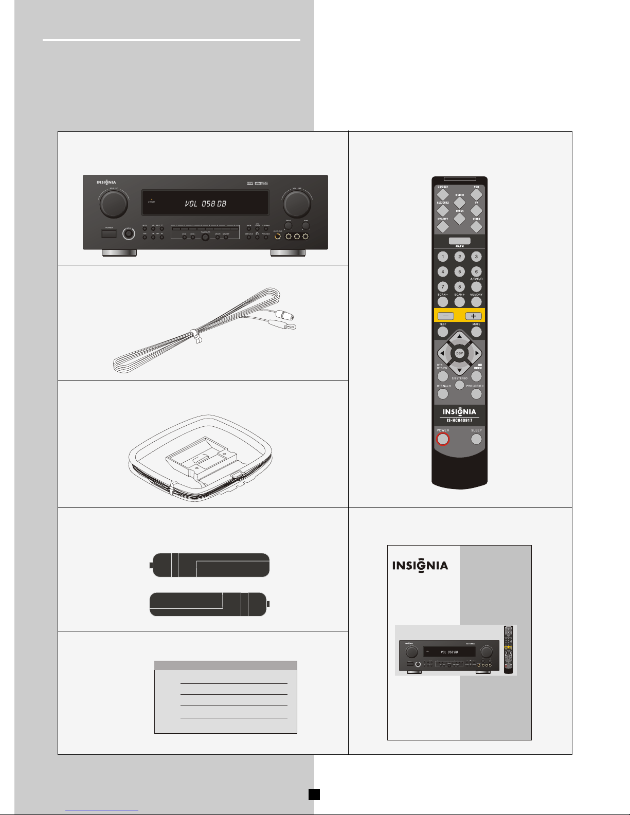
Getting Started
You should receive the following items:
Fittings
One instruction book
Indoor FM antenna
AM loop antenna
One receiver unit
One Remote Control
AAA,R3P,UM-4 batteries
Warranty Card
VOLUME
User's Manual
IS-HC040917
VOLUME
DIGITAL HOME THEATER AMPLIFIER
DIGITAL HOME THEATER AMPLIFIER IS-HC040917
L R V
AUDIO VIDEO INPUT
AAA,R3P,UM-4 batteries
AAA,R3P,UM-4 batteries
DIGITAL HOME THEATER AMPLIFIER IS-HC040917
L R V
AUDIO VIDEO INPUT
DIGITAL HOME THEATER AMPLIFIER IS-HC040917
L R V
AUDIO VIDEO INPUT
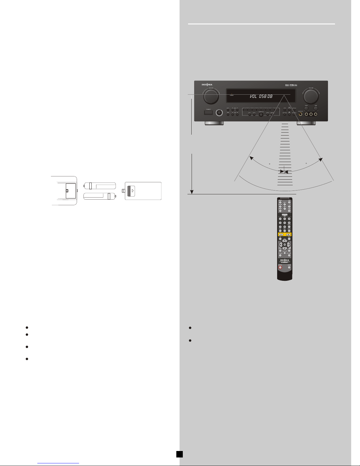
Notes About the Remote Control
If you find that the remote control must be used closer to the
main unit, the batteries are weak. Replace both batteries with
new ones.
Remote Control Operation Range
The area between the remote control and the main unit must be
clear of large obstacles.
Do not expose the remote control sensor to strong lighting,in
particular an inverter type fluorescent lamp.Otherwise,the
remote control may not work properly. If necessary, position the
main unit away from direct lighting.
30
30
Within approximately
6m(19.7feet)
6
VOLUME
Getting Started
Batteries Replacement
Notes
Notes
Since the remote control will be used for many of this unit's
control operations, you should begin by installing the supplied
batteries.
1.Turn the remote control over and slide the battery compartm-
ent cover in the direction of the arrow.
2. Insert the batteries(AAA,R03P,UM-4 TYPE) according to the
polarity markings on the inside of the battery compartment.
3.Close the battery compartment cover.
Use AAA,R3P,UM-4 batteries.
Be sure the polarities are correct.(See the illustration inside the
battery compartment.)
Remove the batteries if the remote control is not used for an
extended period of time.
If batteries leak, dispose of them immediately. Avoid touching
the leaked material and contact with clothing, etc. Clean the
battery compartment thoroughly before installing new batteries.
Installing batteries in the remote controller
7
VIDEO
Getting Started
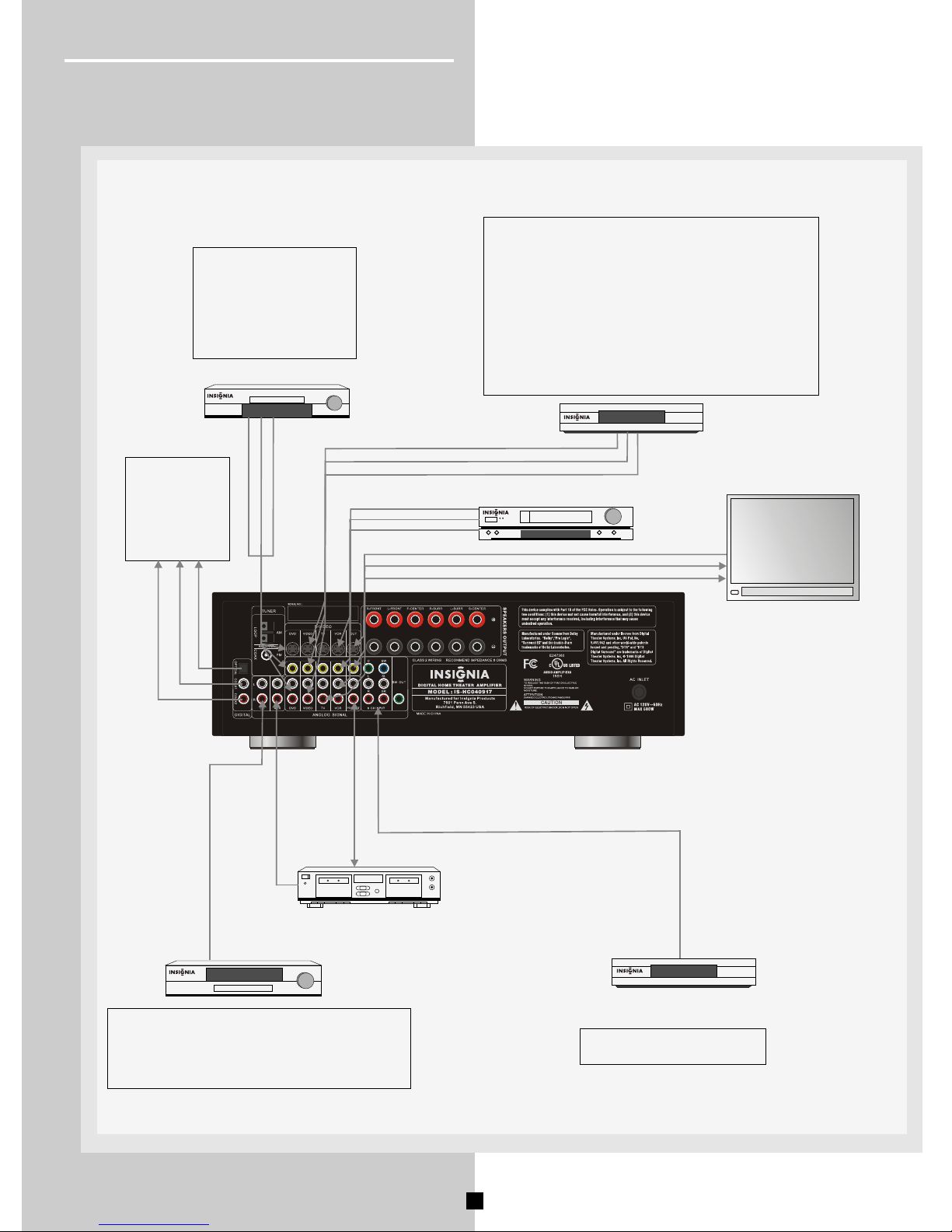
Connecting to Audio-Visual Components
If you have a LD player, DVD player or CD player with a digital output, you can make use of an
optical digital connecting cord(not supplied) or coaxial digital connecting cord (not supplied) to
carry the audio portion of the signal and enjoy Dolby Digital sound quality. One optical or coaxial
cable is needed for each LD player, DVD player or CD player.This receiver provides one optical
and two coaxial digital inputs for the connection of your components. Please connect your com-
ponents(e.g. LD, DVD, or CD) to the appropriate digital inputs and press INPUT button to match
your connection.
Note:
Optical and coax cables carry only the audio portion of the signal. A video connection must also
be established for a LD player and DVD player. S-video provides the best connection for the
video portion of the signal. Composite video (yellow RCA connector) can also be used. It is
important that the same type of cable (S-video or composite) that is connected from the Home
Theater to the TV is used to connect the LD player or DVD player to the Home Theater.
199
aivin
menu
menu
Connect components
capable of outputting Dolby
Digital (e.g. DVD or LD) or
standard PCM(CD) format
digital signals.Read section
on "Digital Connections"
under "Getting Started"
carefully to connect.
CD Player
Tape Deck
VCR
DVD
LD
TV
199
AUDIO OUT(CD)
To LINE IN (Tape Deck)
6 channels output (Decoder etc.)
Multi-Channel
Decoder e.g. DTS
To AUDIO OUT (DVD)
To VIDEO OUT (DVD)
To S-VIDEO OUT (DVD)
To VIDEO OUT (VIDEO)
To AUDIO OUT(VIDEO)
To S-VIDEO OUT (VIDEO)
To AUDIO OUT(VCR)
To VIDEO OUT (VCR)
To S-VIDEO OUT (VCR)
To VIDEO IN (TV)
To AUDIO OUT (TV)
To S-VIDEO IN (TV)
Unit
Rear Panel
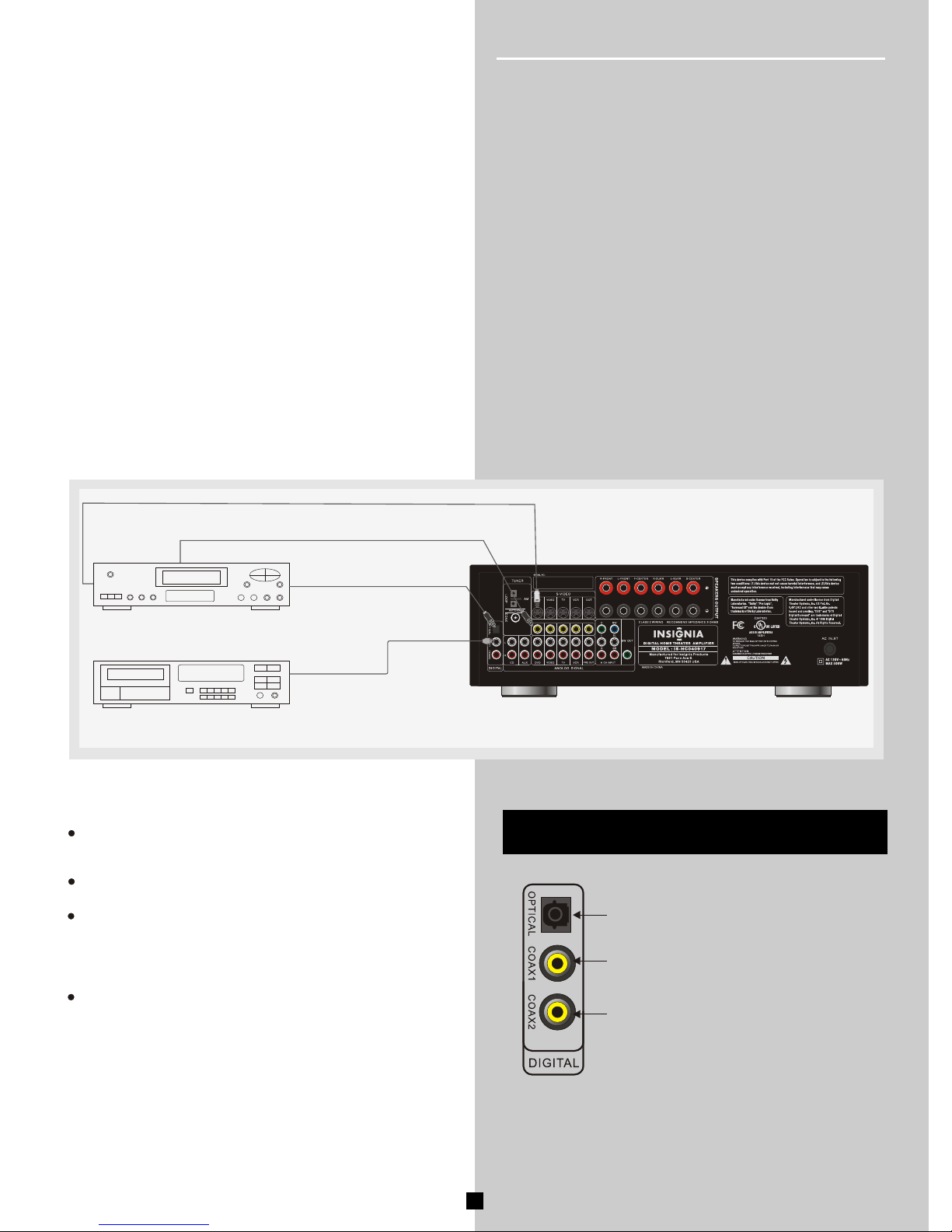
If your CD player is equipped with digital optical jacks, use of optical cable is preferred.
What you need is just one more optical digital connecting cord(not supplied). Plug it in
the digital input jack of the receiver and select OPTICAL.You can enjoy better sound
quality brought to you by the optical cable.
Note: This receiver has one digital optical jack only. Be sure that such connection does
not prevent optical cable connection of other components.
If your video component has a S-Video jack
included, you can make use of it to enjoy
enhanced video quality by connecting it to the
relevant S-Video jack at the rear panel of the
receiver.One Video cable is needed for each
component.
Note: Before plugging in the optical cable or
S-Video cable, make sure to match the shape
of the plug and jack, otherwise, you will not be
able to plug in completely.
See detailed on page 29 chapter "6 Channel External
Input" under "Operating Your Receiver".
VIDEO
Digital Connections
Getting Started
8
It's corresponding video and s-video input
jack is DVD.
It's corresponding video and s-video input
jack is VIDEO.
It's corresponding video and s-video input
jack is TV.
HINT
When you connect an audio/video unit to both of the digital and
analog terminals of this unit, make sure to connect to both
terminals of the same name.
Be sure to attach the covers when the OPTICAL terminals are
not being used, in order to protect the terminals from dust.
In order to make this unit perform successful DTS-decoding the
DTS bitstream must not be altered, manipulated or corrupted in
the process of sending the DTS bitstream from the DIGITAL
OUT terminal of an external unit to a digital signal input terminal
of this unit.
All digital audio signal input terminals are applicable to the
sampling frequency of 32 kHz, 44.1kHz and 48kHz.
If your CD player, LD player, DVD player, TV/satellite tuner, etc,
are equipped with coaxial or optical digital audio signal output
terminals, they can be connected to this unit's COAXIAL or
OPTICAL, or both terminals.
Digital audio signals are transmitted with less loss than analog
audio signals. In addition, digital audio signal connections are
necessary, especially for an LD player, a DVD player or a CD
player to send signals encoded with Dolby Digital or DTS to
this unit.
To make an optical digital connection between this unit and an
external unit, remove the cover from each optical terminal, and
then connect them by using a commercially available optical
fiber cable that conforms to EIAJ standards.Other cables might
not function correctly.
Even if you connect an audio/video unit to the OPTICAL (or
COAXIAL) terminal of this unit, you must keep the unit connec-
ted with the same named analog audio signal terminals of this
unit, because digital signal cannot be recorded by a tape deck
or VCR connected to this unit. You can switch the selection of
input signals between digital and analog easily.
DVD
CD
COAXIAL OUT
OPTICAL OUT
S-VIDEO OUT
VIDEO OUT
Notes
VIDEO
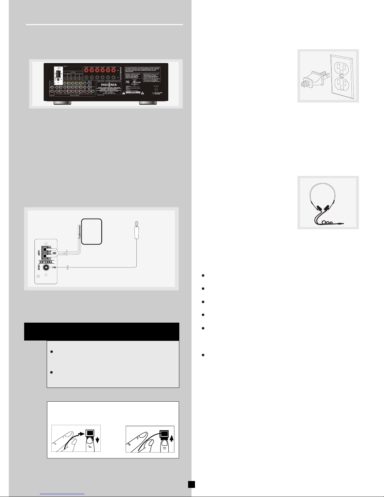
AM Loop Antenna and FM Indoor Antenna
1.
2.
Uncoil the Antenna wire.
Press down on the Antenna tab to open the terminal.
Connecting the Antenna
The AM and FM antennas connect to the AM and FM termInals
nals on the system's back panel.
They must be hooked up in order to receive clear reception.
HINT
For FM reception, extend antenna to its full
length and arrange the Antenna Higher.
For AM reception, rotate the antenna horizontally to get better reception.
1.
2.
AM Antenna
wire Connection
Connecting for Power
Make sure you connect all your
other electronic components and
the speakers before plugging your
receiver into the outlet. Plug the
power cord in the wall outlet,
matching the wide blade of the
plug with the wide slot in the outlet. Be sure to insert the plug
completely.
Using Headphones
To listen privately through your audio
system, use the HEADPHONE jack
on the receiver. However,make sure
you turn down the volume before
you put on the headphones. Increase
the volume to the desired level after
headphones are in place.
Notes:
Do not play your headset at a high volume. Hearing experts
advise against continuous extended play.
If you experience a ringing in your ears, reduce volume or
discontinue use.
Always turn down the volume before connecting your headphones.
The speakers are turned off while the headphones plug is
inserted in the HEADPHONE jack.
When you connect a pair of headphones, the listening mode
is set to Stereo, unless it's already set to 2 CH Stereo. When
you disconnect the headphones, the previous listening mode
is resumed.
When the multichannel input is used, only the front left and
right audio can be heard in the headphones.
9
Getting Started
VIDEO
10
SUB WOOFER
SURROUND RIGHT
SPEAKER
FRONT CENTER
SPEAKER
FRONT RIGHT
SPEAKER
RIGHT
LEFT
RIGHT LEFT
SW OUT
Use this jack on the
middle back panel to
connect another
powered subwoofer
other than the one
supplied.
SURROUND CENTRE
SPEAKER
Getting Started
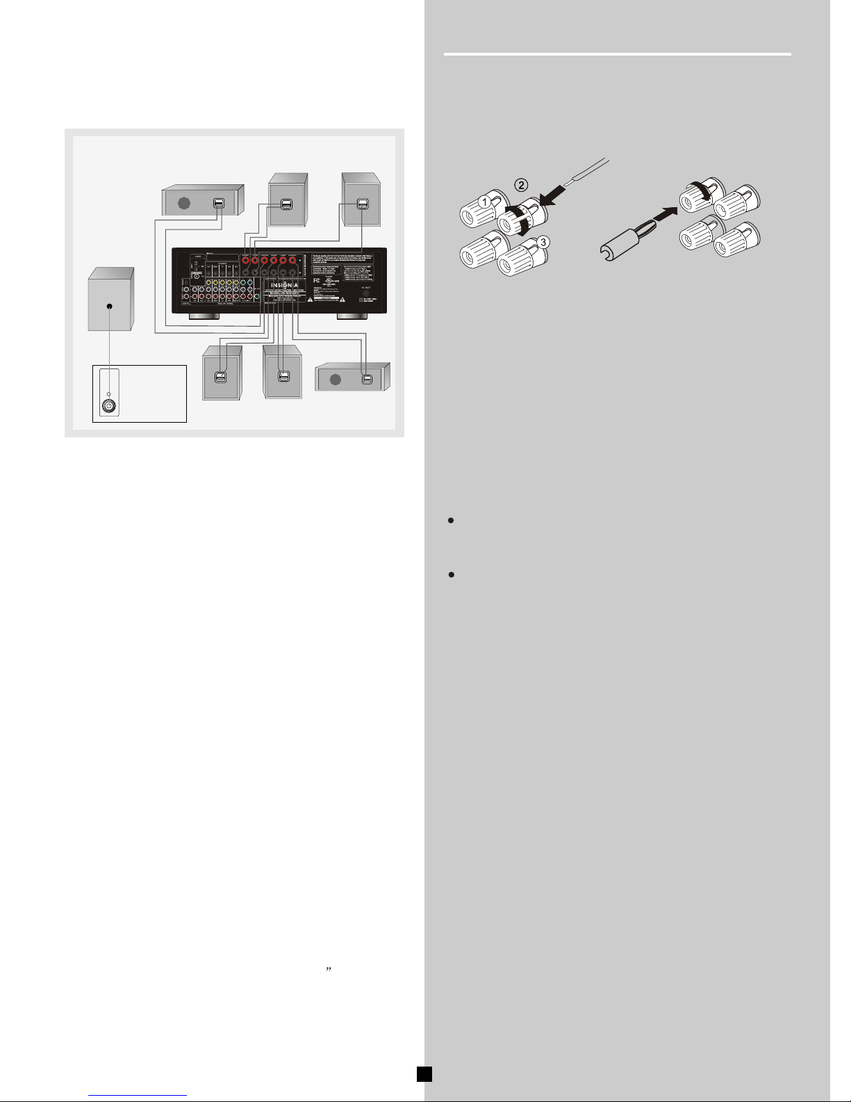
Connecting the Speakers
Speakers
Connecting the Main ,Center, Rear Speaker
Speaker Polarity
When connecting the speakers, make sure the polarities ( "+"
speaker wire to "+" on the receiver) of speaker wires and
terminals are matched. If the cords are reversed, the sound
will be distorted and will lack bass ("out of phase" effect).
Connecting the Subwoofer
To connect your own powered subwoofer, a mono aural audio
cord (not supplied) is needed (RCA terminal).
This receiver offers a high flexibility for user to use a large
variety of speakers and subwoofers. For more information
please refer to section "Speaker Setting" in "Operating Your
Receiver" on page 20.
MAKE SURE TO CONNECT 6-8 OHM SPEAKERS ONLY.
Do not let the bare speaker wires touch each other or any metal
part of this unit. This could damage this unit or the speakers,or both.
Connect the speakers terminals to your speakers with the wire of
the wire of the proper gauge (keep as short as possible). if the
connections are faulty. no sound will be heard from the speakers.
Method 1
Method 2
Or you also may use banana plug.
SURROUND LEFT
SPEAKER
FRONT LEFT
SPEAKER
You will need to use 7 speakers with the unit (Front Left, Front
Right, Front Center, Surround Left Surround center, Surround
Right and subwoofer). In order to enjoy good surround effects
all six speaker need to be connected to the receiver.
At least two front speakers (Front left and right) are required.
For better sound quality, Center speaker, Surround speakers
and Subwoofer should also be connected. Adding Center and
Surround speakers will enhance surround effects. Adding a
Subwoofer will increase bass response.
If you want to enjoy full range of sound effects, with small
speakers,it is a must to use the subwoofer with the speakers to
maintain adequate bass signal.
1.
2.
3.
Loosen the knob.
Insert the bare wire.[Remove approx 5mm(1/4 ) insulation
from the speaker wires.]
Tighten the knob and secure the wire.
Notes
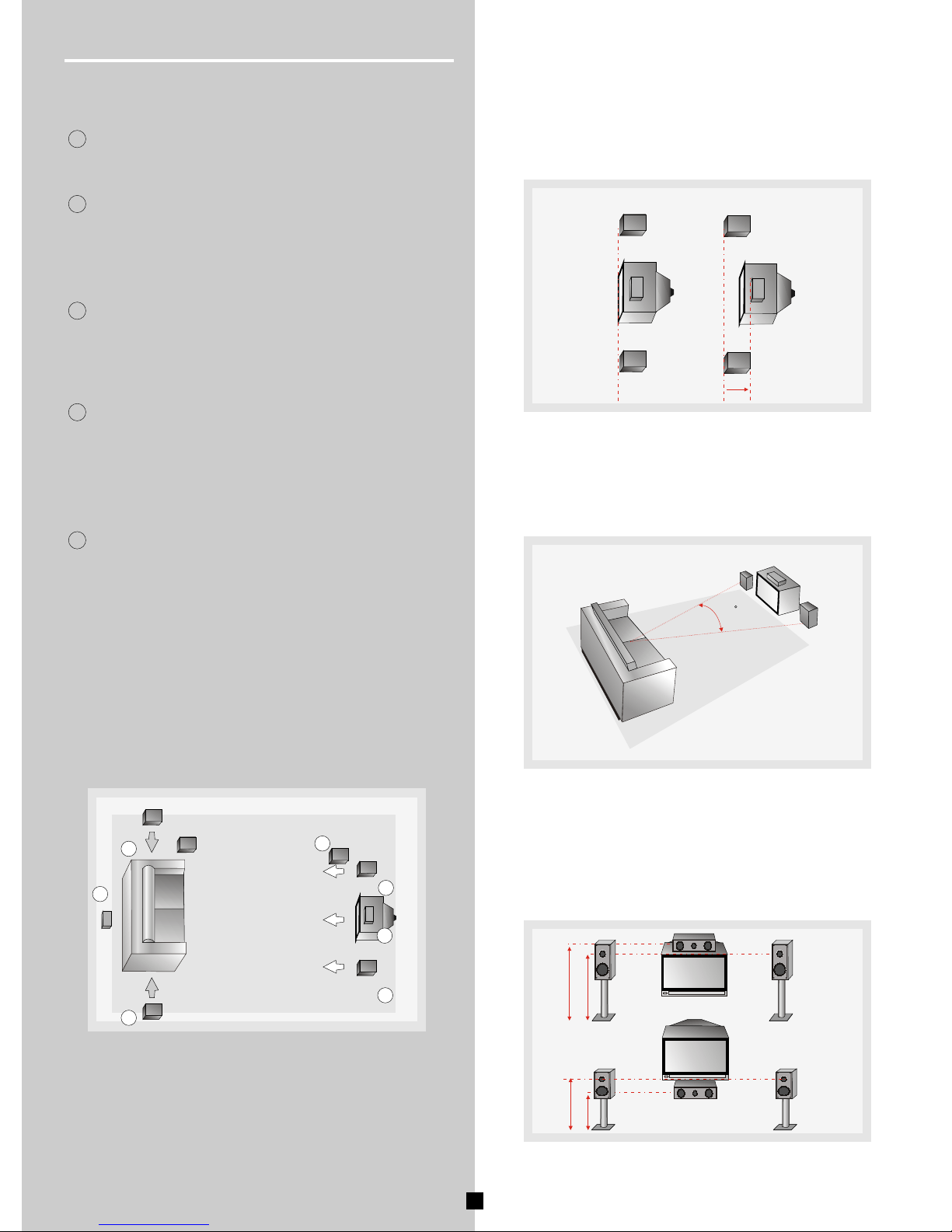
Positioning Your Speaker
Alignment
Align the center speaker evenly with (A),or slightly behind (B),
the left and right speakers, but not ahead of them.
Getting Started
Left, Right(Front Speakers)
1
They carry primarily music and sound effects.
Center
2
In surround mode, the center speaker carries much of the
dialogue as well as music and effects. It should beset between
the left and right speakers.
Surround Left, Right(Rear Speakers)
3
Their overall sound balance should be as close as possible
to the front speakers. Proper placement is vital to establish
an evenly distributed sound field.
Magnetic shielding
Speakers placed less than two feet from the TV set must be
magnetically shielded in order to prevent picture distortion.It is
not recommended to place the rear speakers near the TV set.
Front Speaker Placement
Even if you can't duplicate ideal home theater setup exactly,
the suggestions for speaker placement that follow will help
you get good results.
Angle
Placing the left and right speakers to form a 45-degree angle
with your favorite viewing position will duplicate the soundtrack
mixer's perspective.
Height
The mid-and high-frequency drivers of the three front speakers
should be as possible to the same height. This often requires
placing the center speaker directly atop(A) or beneath(B) the
TV set.
A
B
45
A
B
Surround Center(surround center Speakers)
4
The surround center speaker supplements the surround
speakers and provides for more realistic front-to-back
transitions. Place the speaker directly behind the listening
position and at the same height as the surround speakers.
11
Subwoofer
A subwoofer is designed to reproduce powerful low bass
effects(explosions,the rumble of spaceships, etc.) which
dramatically heightens involvement with the action on the
screen. It is therefore recommended to connect subwoofer
when small speakers are use.
5
1
2
3
3
1
Courtesy Dolby Laboratories
4
5
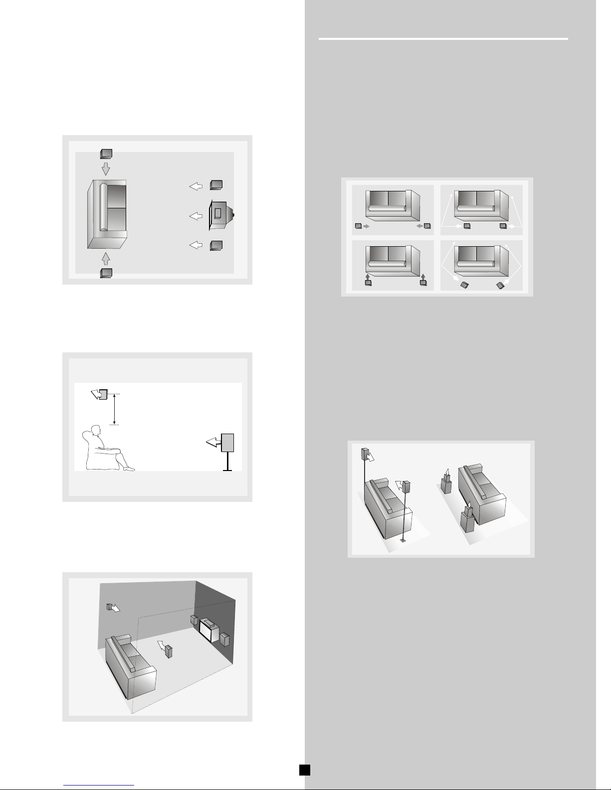
Preferred Surround Placement
Height
If space permits, install surrounds 2-3 feet above viewers.
This helps to minimize localization effects.
If possible, place surround speaker to either side of the listen-
ing area, not behind it.
¶¨Î»
Aiming surrounds straight across the room, not down at
audiences, helps create a more open, spacious surround
sound field.
Alternative Surround Placement
Courtesy Dolby Laboratories
Courtesy Dolby Laboratories
Courtesy Dolby Laboratories
2-3feet
Rear wall
If rear wall mounting is the only choice, aim the speakers at
each other (A),towards the front (B) or even towards the side-
walls (C,D). Experiment with placement until surround sounds
seem to envelop you, rather than coming from behind you.
NO Adjacent Walls
Surrounds can go on stands facing each other to approximate
the preferred sidewall mounting(A), or to the sides or rear of
the viewing area aimed upwards. In the latter case, they can
go right on the floor, or preferably, a few feet off the floor such
as on end tables(B).
Courtesy Dolby Laboratories
Courtesy Dolby Laboratories
A B
A c
DB
Location
12
Getting Started
 Loading...