

Page 1

Before installing or starting this unit for the first
time, this manual should be studied carefully to
obtain a working knowledge of the unit and/or the
duties to be performed while operating and
maintaining the unit.
RETAIN THIS MANUAL WITH UNIT. This Technical
manual contains IMPORTANT SAFETY DATA and
should be kept with the unit at all times.
Ingersoll Rand
X41 System Automation
Operator’s Manual
C.C.N. : 80443617
More Than Air. Answers.
Online answers: http://www.air.irco.com
1
REV. : A
DATE : APRIL 2007
Page 2

SECTION 1 — TABLE OF CONTENTS
SECTION 1 — TABLE OF CONTENTS................................ 2
SECTION 2 — INTRODUCTION........................................ 4
SECTION 3 — SAFETY..................................................... 4
INSTALLATION ............................................................ 4
OPERATION................................................................. 4
MAINTENANCE AND REPAIR ........................................ 5
SECTION 4 — COMPRESSOR CONNECTION & CONTROL.. 6
PRESSURE DETECTION AND CONTROL......................... 6
SECTION 5 — DISPLAY AND MENU OPERATION .............. 7
DISPLAY ITEM STRUCTURE .......................................... 9
NORMAL OPERATIONAL DISPLAY (MENU PAGE P00)..... 9
INFORMATION DISPLAYS ............................................. 9
Status Display.......................................................... 9
Sequence Rotation................................................. 10
OPERATIONAL FUNCTIONS........................................ 11
STOP ..................................................................... 11
START ................................................................... 11
POWER FAILURE AUTO-RESTART ............................ 11
FAILURE MODE....................................................... 11
RESET .................................................................... 11
SECTION 6 — CONTROL FEATURES AND FUNCTIONS.... 12
STANDARD CONTROL FEATURES AND FUNCTIONS.... 12
PRESSURE CONTROL .............................................. 12
ANTI-CYCLING CONTROL ....................................... 13
TOLERANCE ........................................................... 13
DAMPING............................................................... 13
SYSTEM VOLUME ................................................... 14
STANDARD SEQUENCE CONTROL STRATEGY.......... 15
FIRST IN LAST OUT MODE (FILO) ............................ 15
SEQUENCE ROTATION EVENTS ............................... 15
ADVANCED CONTROL FEATURES AND FUNCTIONS ... 16
ADVANCED SEQUENCE CONTROL STRATEGIES ....... 16
Variable Energy Control Mode (VEC) ...................... 16
Priority Settings ..................................................... 16
Tables and the Pressure Schedule.......................... 17
Pressure Schedule ................................................. 18
Pre-fill.................................................................... 18
ALTERNATE CONTROL FEATURES AND FUNCTIONS... 20
Equal Hours Run Mode .......................................... 20
First In First Out Mode (FIFO) ................................. 20
SECTION 7 — INSTALLATION ........................................22
Unit Location .............................................................22
Power Supply .............................................................22
Pressure Sensor Location ...........................................22
Generation Side Pressure Control ...........................22
System (Demand Side) Pressure Control .................23
Pressure Sensor Connection ......................................23
IR-PCB Interface Module.............................................23
Input Functions .........................................................24
Ready Input ............................................................24
Ready Input, Alternative Connection Method ..........25
Run Input ...............................................................26
Warning Input (optional).........................................27
Output Functions.......................................................27
Pressure Switch Regulation.....................................28
Digital Regulation Control Terminal C01 ................29
Service Maintenance Switch ....................................30
Auxiliary Input (Option)..........................................30
Auxiliary Output (Option) .......................................31
RS485 Communications .........................................31
SECTION 8 — FAULT CODES..........................................32
X4I Compressor Fault Indications, Types, and Codes:32
Alarm (Warning) .....................................................32
Not Available..........................................................32
Compressor Inhibited, Removed From Service........33
Service/Maintenance ..............................................33
Communications Disruption ...................................33
Special Controller Fault Codes................................33
Error Log ................................................................33
SECTION 9 — Commissioning .......................................35
Physical Checks .........................................................35
Pressure Display ........................................................35
X4I Quick Set-up Configuration..................................35
SECTION 10 — System Configuration............................36
Accessing the X4I Configuration Screens ...................36
User Configuration: Tab S01......................................37
Real Time Clock Settings ........................................37
Pressure Schedule Settings.....................................38
Auto Restart Settings..............................................39
Rotation Interval Settings .......................................40
2
Page 3

Table Select Settings ............................................. 41
Backlight Adjust Settings ....................................... 42
User Configuration: Tab S02..................................... 42
Units Settings ........................................................ 43
Number of Compressors Settings .......................... 43
Maximum Pressure Alarm Settings ........................ 44
Stop Control Settings............................................. 45
Tolerance Settings ................................................. 46
Damping Settings .................................................. 47
Pressure Change Settings ...................................... 47
Auxiliary Input Settings ......................................... 48
Auxiliary Output Settings ...................................... 49
Error Log Reset...................................................... 50
User Configuration: Tab S03..................................... 50
Pressure Sensor – Offset ........................................ 51
Pressure Sensor – Range Settings .......................... 51
Compressor Configuration: Tab C01 ........................ 52
Compressor Run Hours ......................................... 53
Compressor Configuration: Tab C02 ........................ 53
Compressor Connection Method ........................... 54
Compressor Table Configuration: Tab T01 ............... 57
High Pressure Setpoint Settings............................. 57
Low Pressure Setpoint Settings .............................. 58
Minimum Pressure Alarm Settings ..........................58
Sequence Strategy Settings.....................................59
Compressor #1 Priority Settings .............................60
Compressor #2 through 4 Priority Settings.............60
Pressure Schedule Configuration P01 Tab Screen ......61
Pressure Schedule Settings.....................................61
Pre-fill Configuration P02 Tab Screen .....................62
Pre-fill Function Settings.........................................63
Pre-fill Time Settings ..............................................64
Pre-fill Pressure Settings.........................................65
Pre-fill Compressor #1 Settings ..............................65
Pre-fill Compressor #2 through 4 Settings..............66
Diagnostics D01 Tab Screen ......................................67
Diagnostics Settings...............................................67
X4I Controller Diagnostics......................................68
Digital Inputs .........................................................68
Relay Outputs.........................................................68
Analog Inputs.........................................................69
Analog Output........................................................69
Total Unit Reset and Default Values........................69
Parts List.......................................................................73
Technical Data ..............................................................74
Diagrams ......................................................................75
3
Page 4
SECTION 2 — INTRODUCTION
The X4I is a specialized controller designed to provide safe, reliable, and energy-efficient control of your compressed air
system. The X4I is capable of controlling up to four positive displacement air compressors. The compressors may have
electro-pneumatic or microprocessor based controls. The X4I is completely customizable to meet the specific needs of
your compressed air system.
SECTION 3 — SAFETY
WARNING :
!
WARNING :
WARNING :
!
WARNING :
• Before installing or operating the X4I, take time to carefully read all the instructions contained in this
manual, all compressor manuals, and all manuals of any other peripheral devices that may be installed or
connected to the unit.
• Electricity and compressed air have the potential to cause severe personal injury or property damage.
• The operator should use common sense and good working practices while operating and maintaining this
system. All applicable codes should be strictly adhered to.
• Maintenance must be performed by adequately qualified personnel that are equipped with the proper
tools.
INSTALLATION
• Installation work must only be carried out by a competent person under qualified supervision.
• A fused isolation switch must be fitted between the main power supply and the X4I.
• The X4I should be mounted in such a location as to allow operational and maintenance access without
obstruction or hazard and to allow clear visibility of indicators at all times.
• If raised platforms are required to provide access to the X4I, they must not interfere with normal operation
or obstruct access. Platforms and stairs should be of grid or plate construction with safety rails on all open
sides.
Risk of Danger
Risk of Electric Shock
Risk of High Pressure
Consult Manual
OPERATION
• The X4I must only be operated by competent personnel under qualified supervision.
• Never remove or tamper with safety devices, guards or insulation materials fitted to the X4I.
• The X4I must only be operated at the supply voltage and frequency for which it is designed.
• When main power is switched on, lethal voltages are present in the electrical circuits and extreme caution
must be exercised whenever it is necessary to carry out any work on the unit.
• Do not open access panels or touch electrical components while voltage is applied unless it is necessary
for measurements, tests or adjustments. Such work should be carried out only by a qualified electrician
equipped with the correct tools and wearing appropriate protection against electrical hazards.
• All air compressors and/or other equipment connected to the unit should have a warning sign attached
stating “THIS UNIT MAY START WITHOUT WARNING” next to the display panel.
• If an air compressor and/or other equipment connected to the unit is to be started remotely, attach two
warning signs to the equipment stating “THIS UNIT CAN BE STARTED REMOTELY”. Attach one sign in a
4
Page 5

prominent location on the outside of the equipment, and the other sign inside the equipment control
compartment.
MAINTENANCE AND REPAIR
• Maintenance, repairs or modifications must only be carried out by competent personnel under qualified
supervision.
• If replacement parts are required, use only genuine parts from the original equipment manufacturer, or an
alternative approved source.
• Carry out the following operations before opening or removing any access panels or carrying out any work
on the X4I:
i. Isolate the X4I from the main electrical power supply. Lock the isolator in the “OFF” position and
remove the fuses.
ii. Attach labels to the isolator switch and to the unit stating “WORK IN PROGRESS - DO NOT APPLY
VOLTAGE”. Do not switch on electrical power or attempt to start the X4I if such a warning label is
attached.
• Make sure that all instructions concerning operation and maintenance are strictly followed and that the
complete unit, with all accessories and safety devices, is kept in good working order.
• The accuracy of sensor devices must be checked on a regular basis. They must be calibrated when
acceptable tolerances are exceeded. Always ensure any pressure within the compressed air system is
safely vented to atmosphere before attempting to remove or install a sensor device.
• The X4I must only be cleaned with a damp cloth, using mild detergents if necessary. Avoid the use of any
substances containing corrosive acids or alkalis.
• Do not paint the control faceplate or obscure any indicators, controls, instructions or warnings.
5
Page 6
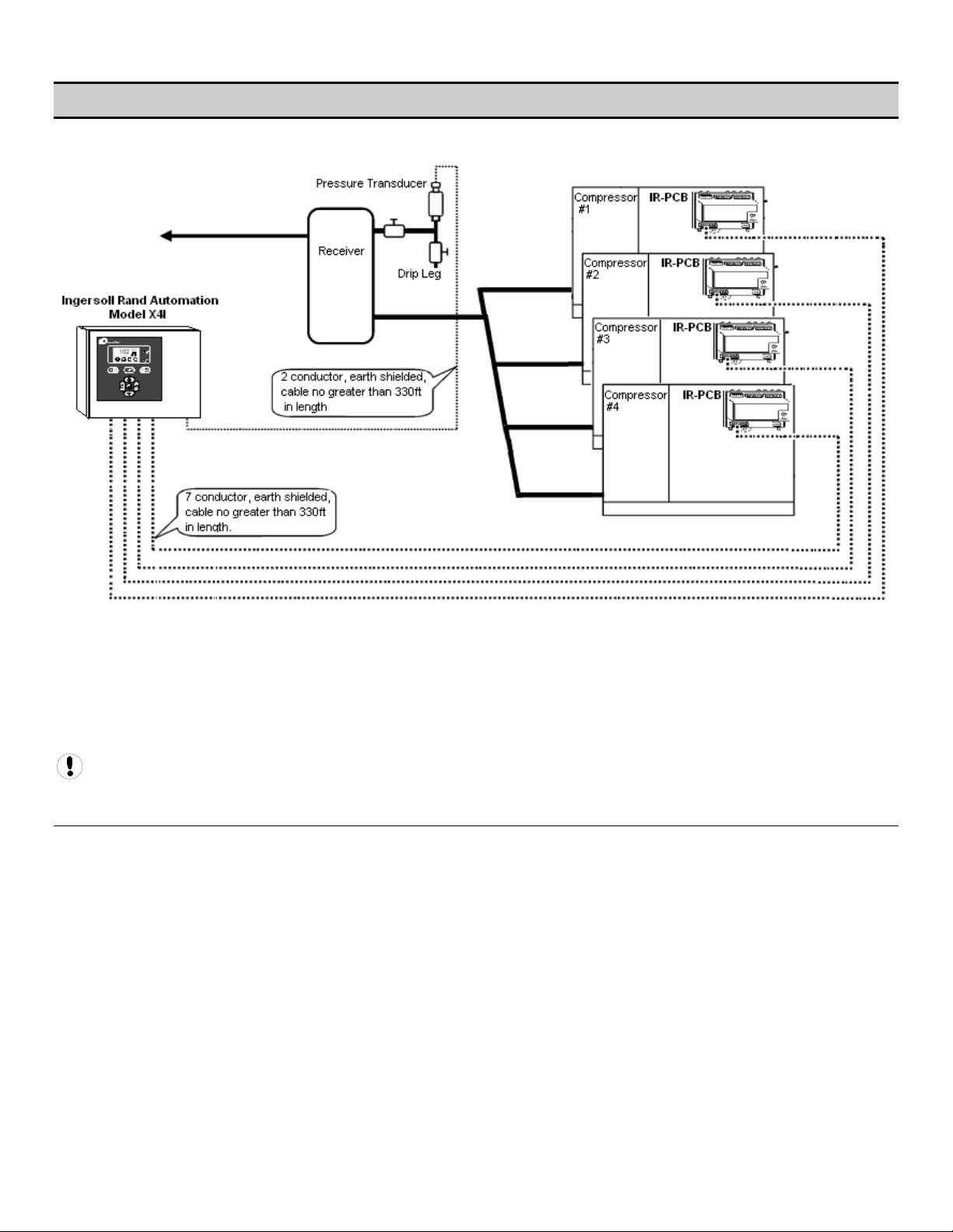
SECTION 4 — COMPRESSOR CONNECTION AND CONTROL
Each air compressor in your system can be interfaced to the X4I using the included IR-PCB interface modules. Any
compressor with an available control voltage of 12-250V (either 50Hz or 60Hz) can be controlled by the X4I.
The interface module is mounted inside the compressor’s starter panel and connected to the X4I by using a shielded 7conductor cable, or individual cables run through conduit.
Each air compressor must be equipped with an online/offline pressure regulation system capable of accepting a remote
load/unload signal through a volt-free switching contact or a single electro-mechanical pressure switch.
Consult the air compressor manual or your air compressor supplier/specialist for details before installing the X4I.
PRESSURE DETECTION AND CONTROL
The X4I utilizes the signal from a 4-20 ma pressure sensor that is mounted remotely from the X4I in a suitable location in
the compressed air system.
The factory default settings for the pressure sensor is 0–232 PSI (16 bar), but the X4I can accept any pressure sensor with
a 4–20 ma output and a range of up to 8700 PSI (600 bar).
6
Page 7

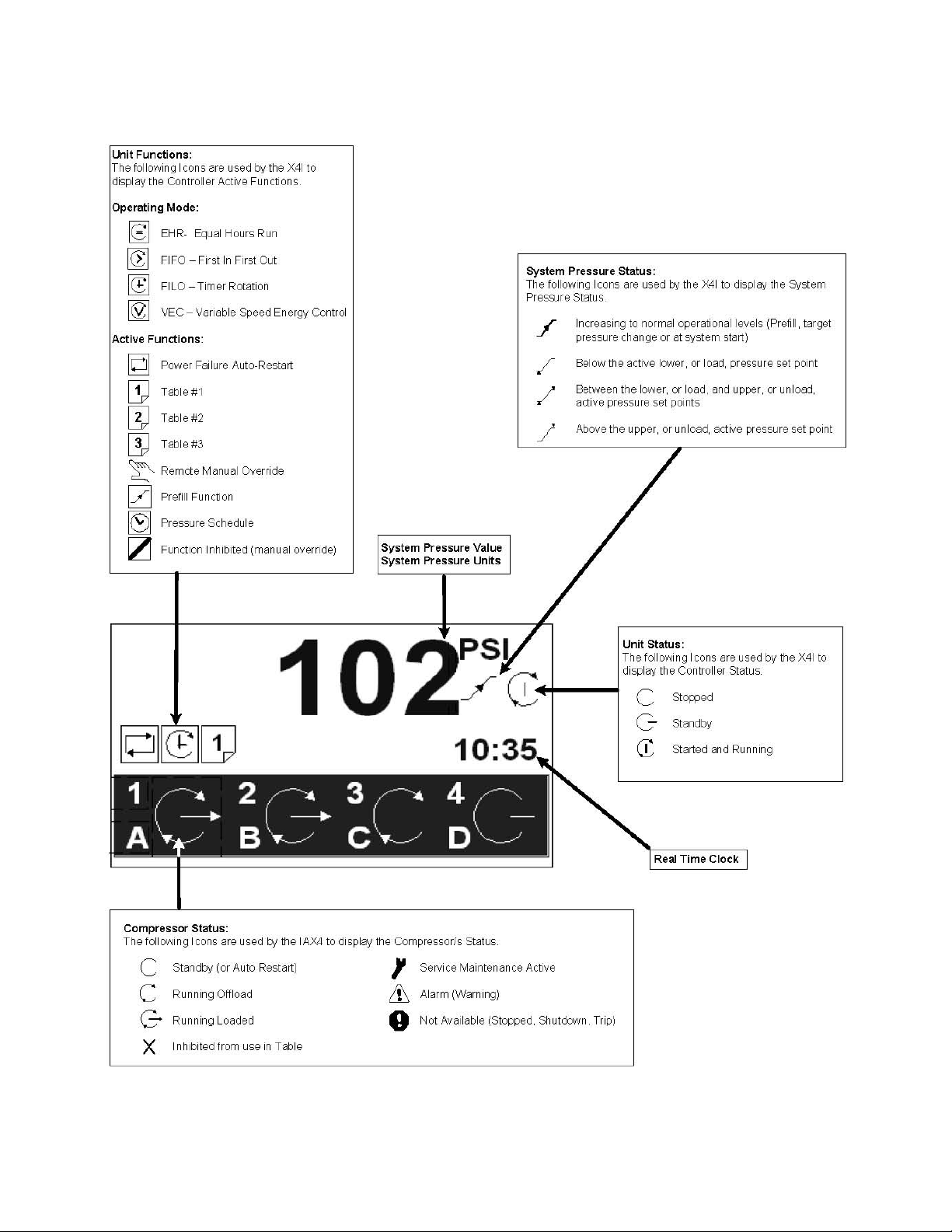
SECTION 5 — DISPLAY AND MENU OPERATION
The Main Display and the keypad and navigation buttons on the X4I are depicted below and provide the following
functionality:
7
Page 8
8
Page 9
DISPLAY ITEM STRUCTURE
Operational system status and values are accessible from the normal user display. To view status or values that are not
normally visible on the default screen, press UP or DOWN. All standard user display items are viewable only and cannot be
adjusted. The standard user display items are regarded as “Menu Page 00” items.
All adjustable value, parameter or option item displays are grouped into “menu mode” lists. Items are assigned to a list
according to type and classification. Item lists are identified by page number (or menu number). All adjustable parameters
and options are assigned to menu mode pages “P01” or higher.
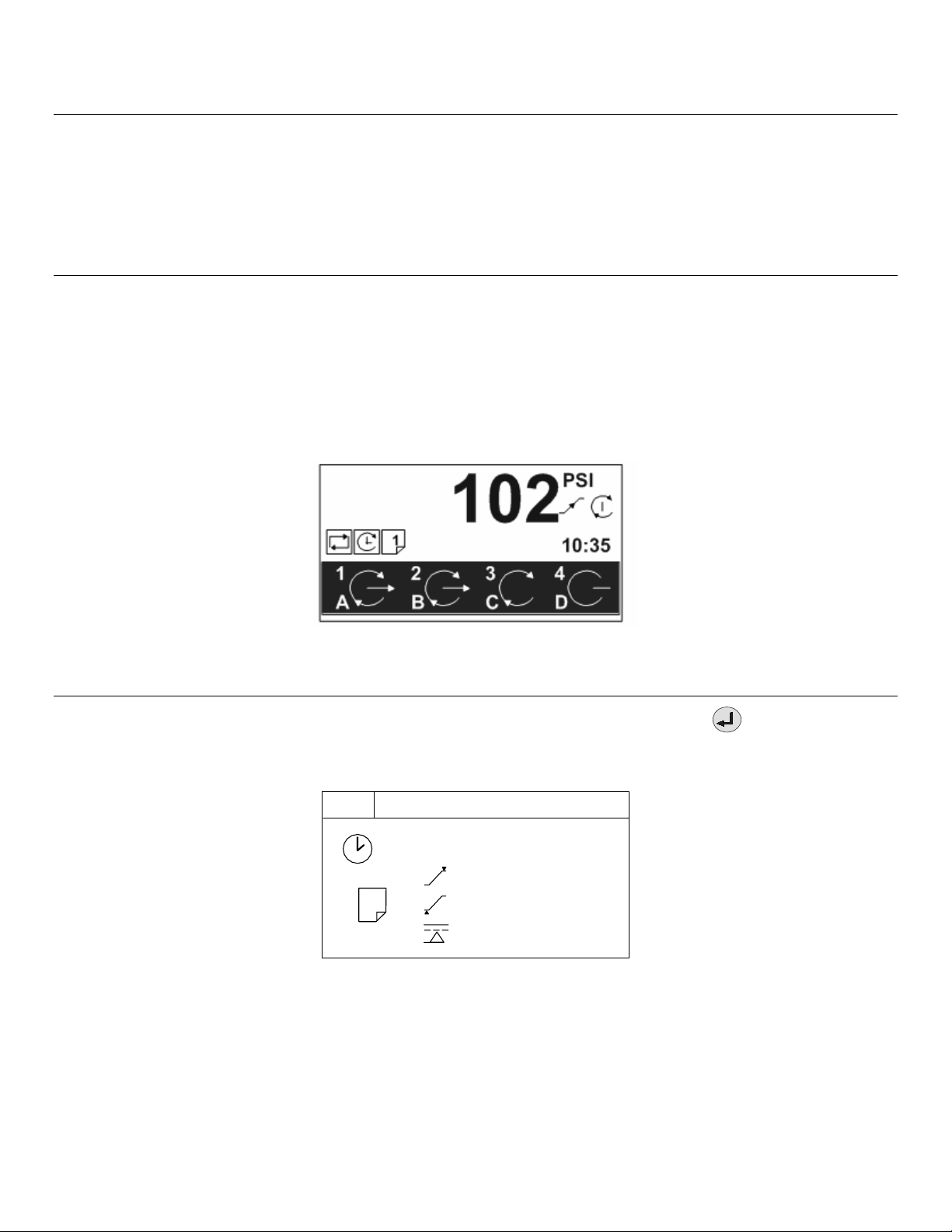
NORMAL OPERATIONAL DISPLAY (MENU PAGE P00)
At controller initialization, all display elements and LED indicators are switched on for three seconds. The display will then
show the software version code for a further three seconds before initialization is complete and the normal operating
display (“Page P00”) is shown. In normal operational display mode, the main display will continuously show the detected
system pressure and the Item display will show the first item of the “Page 00” menu. User menu “items” can be selected
using the UP or DOWN buttons at any time. Pressing the ENTER button will lock any selected item display and inhibit return
to the default display. When an item display is locked, the “lock key” symbol will be shown. To unlock an item display,
press UP or DOWN to view an alternative item display or press RESET or ESCAPE. No item values, options or parameters can
be adjusted in “Page P00”. If a fault condition occurs, the fault code becomes the first list item and the display will
automatically jump to display the fault code. More than one active fault code item can exist at any one time and can be
viewed by pressing UP or DOWN. The most recent “active” fault will be at the top of the list.
Main Status Screen
INFORMATION DISPLAYS
To view detailed information applicable to the selected User menu display item press the ENTER button:
STATUS DISPLAY
P00
#1
1
Status Display Screen
18:00 T02
102
98
80
psi
psi
psi
9
Page 10
If the ‘Pressure Schedule’ feature is active; shows the day of the week (#1), the time of day (18:00) and the table to be
used (T02) of the next scheduled instruction to be executed.
1
The current active ‘Table’ (T01)
Upper, or unload, pressure setpoint
Lower, or load, pressure setpoint
Minimum pressure Alarm (Warning)
Press the ESCAPE
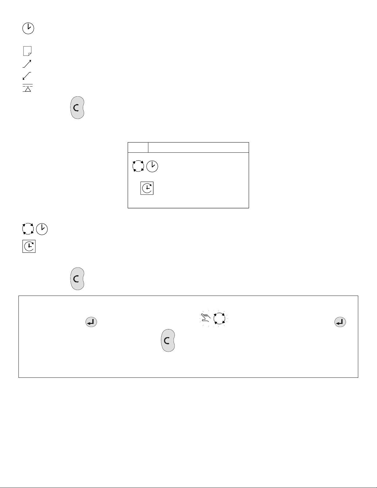
SEQUENCE ROTATION
button to return to the normal operational display screen.
P00
#4 18:00
18 / 05 / 2006
A B C D
Sequence Rotation Display Screen
Day of the week (#4: Thursday), the time of day (18:00) and the date (18/05/2006) of the next automated
sequence rotation event.
The active ‘mode’ of operation
ABCD The current active rotation sequence assignment.
Press the ESCAPE
button to return to the normal operational display screen.
NOTE: The sequence assignment can be manually rotated at any time. When viewing the “Sequence Rotation” information
screen press the ENTER button. The manual rotation symbols will appear and flash. Press the ENTER
button to execute a manual rotation or the ESCAPE button to abandon the manual rotation.
Automated sequence rotation is not disrupted by a manual rotation; the next scheduled automated sequence rotation
event will still occur.
10
Page 11
OPERATIONAL FUNCTIONS
STOP
To stop the X4I, press STOP. Dependent on the setup and configuration of the X4I, the compressors will function as
follows:
• If parameter PC=0, then pressure regulation control is automatically transferred back to each compressor.
The compressor(s) will continue to operate using the pressure settings programmed or set in the
individual compressor controller(s).
• If parameter PC=1, then the X4I will hold each compressor in an offload state. If the compressor is
equipped with a main motor run-on-time function, the compressor will run offload for a period of time and
then stop into a “standby” or “auto restart” state.
The design of some air compressor control systems may inhibit automatic transfer of pressure regulation control to
local operation mode. In this instance, the compressor will not continue production of compressed air. Consult the air
compressor manual or your air compressor supplier/specialist for details before installing the X4I.
START
To start the X4I, press START. If the pre-fill function is enabled, and system pressure is below the set pre-fill pressure, the
system will enter pre-fill mode for the set pre-fill time.
See the section on pre-fill for more information.
To manually skip the pre-fill function, press and hold START for several seconds. When pre-fill is complete, if
applicable, the X4I will enter normal operating mode. The X4I will operate in accordance with the parameters and options
set in the active “table”.
See the section on tables for more information.
Each compressor in the system must be started (running or in a standby or auto restart condition) before X4I control
of the compressor can be established. The X4I will not start a compressor that is in a stopped condition.
POWER FAILURE AUTO-RESTART
If the power failure auto-restart function is enabled, the X4I will automatically start when power is restored after a
disruption or failure, if the X4I was in a “started” state when the power disruption or failure occurred.
NOTE: The X4I will not automatically restart if the X4I was in a stopped state when the power disruption or failure
occurred.
FAILURE MODE
If the X4I experiences a disruption to normal control, or an X4I shutdown fault occurs, pressure regulation control is
automatically transferred back to each compressor. The compressor(s) will continue to operate using the pressure settings
programmed or set in the individual compressor controller(s).
RESET
To reset an X4I alarm (warning) or shutdown condition, press RESET. Compressor alarm (warning) conditions are
automatically reset when the condition has been resolved and reset on the compressor. “Compressor not available”
(shutdown, trip) conditions are automatically reset when the condition has been resolved and reset on the compressor and
the compressor has been restarted.
11
Page 12

SECTION 6 — CONTROL FEATURES AND FUNCTIONS
STANDARD CONTROL FEATURES AND FUNCTIONS
PRESSURE CONTROL
Pressure control is achieved by maintaining the system pressure within an acceptable range, or pressure band, which is
defined and programmed by the user. Pressure will rise in the band when system demand is less than the loaded
compressor’s output. Pressure will fall in the band when system demand is greater than the loaded compressor’s output.
Simply stated, pressure control is achieved by unloading and loading compressors to closely match compressor output
with system demand within a specified pressure band.
Variable speed compressors also operate within the pressure band and actively match compressor output with demand by
speeding up and slowing down around a target pressure defined by the exact midpoint of the pressure band.
Refer to the illustration below. The X4I functions by keeping the system pressure inside of an acceptable pressure range
defined by the user. Compressors will load and unload in order to keep the pressure between the high pressure setpoint
(PH) and the low pressure setpoint (PL), both of which are user adjustable. The pressure control algorithms will attempt to
keep the pressure toward the midpoint of this pressure band. This midpoint is known as the system target pressure (PT).
a
b
PH
PT
PL
Typical System Pressure vs. Time
As pressure rises to point “a”, the compressor will unload based on the sequencing algorithm. System pressure is then
allowed to decrease due to the drop in supply until point “b” is reached. Once point “b” is reached, the X4I will load the
next compressor in the sequence to match the air demand. This cycle will repeat as long as the X4I is able to keep the
system air pressure between PH and PL.
When a compressed air system includes one or more variable speed compressors, each variable speed compressor must
have its target pressure (on its local controller) set to the system target pressure.
The variable speed compressors in the system will run on their target pressure and smooth out the variations in system
pressure. This assumes that system demand does not vary more than the capacity of the variable speed compressor.
A variable speed compressor will be included in the load/unload sequence and be controlled exactly as a fixed speed
machine with the exception of speed control to maintain target pressure.
Refer to the illustration below. If the system demand increases significantly or quickly and the capacity of the loaded
compressor is insufficient to meet the demand, the system pressure will continue to decline at a slower rate. The X4I will
then calculate the instant at which the next compressor is to be loaded. This instant, at point “c”, is dependent on the rate
of change of the system pressure and the user adjustable anti-cycling control settings.
a
b
c
PH
PT
PL
Compressor Supply is Insufficient to Maintain System Pressure
The same logic will come into effect if the system pressure rises above the PH setpoint due to a significant or abrupt
reduction in demand.
12
Page 13
There are many variables that go into determining the stability and control of the system pressure, only some of which are
able to be controlled by the X4I. System storage, air compressor capacity, and air demand all need to be analyzed by
experienced professionals to determine the best installation for your system. Tolerance (TO) and damping (DA) can be
used for minor tuning of the system.
ANTI-CYCLING CONTROL
The most efficient way to utilize most air compressors is either fully loaded or off, with the exception of variable speed
compressors which can operate efficiently at reduced loading. Compressor cycling (start-load-unload-stop, etc.) is essential
to maintain pressure control. Excessive cycling, however, can result in poor compressor efficiency as well as increased
maintenance.
Anti-cycling control is incorporated to help ensure that only the compressors that are actually required are started and
operating while all others are kept off. Anti-cycling control includes a pressure tolerance range or band, defined by the
user, which is outside of the primary pressure band. Inside the tolerance band, an active control ageratum continually
analyzes pressure dynamics to determine the last possible second to add or cycle another compressor into the system.
This control is further enhanced by the ability to fine tune the tolerance band settings and algorithm processing time
(damping).
TOLERANCE
Tolerance is a user adjustable setting that determines how far above the PH setpoint and below the PL setpoint system
pressure will be allowed to stray. Tolerance keeps the X4I from overcompensating in the event of a temporary significant
increase or decrease in system demand.
PH + TO
TO
PH
PT
PL
TO
PL - TO
Tolerance in Relation to PH and PL
Tolerance is expressed as a pressure defining the width of band above PH and below PL in which energy efficient control
will still be in effect.
When system pressure is in the tolerance band, the X4I will continuously calculate the moment at which compressors will
be loaded or unloaded based on the rate of change of system pressure. When the system pressure strays outside of the
tolerance band, the X4I will abandon energy efficiency and begin to protect the system air pressure at all costs.
Tolerance will essentially calculate a new PH or PL setpoint based on the rate of change of the pressure and wait as long as
possible to load or unload a compressor while still maintaining the integrity of the system pressure.
When the compressed air system storage is relatively small compared to the system demand, and fluctuations are large
and quick, the tolerance band setting should be increased to maintain energy efficient operation and avoid a situation in
which multiple compressors are loaded just to be unloaded moments later.
When the compressed air system is relatively large compared to system demand and fluctuations are smaller and slower,
the tolerance band can be reduced to improve pressure control and maintain energy efficient operation.
The factory default setting for tolerance is 3.0 PSI. This setting is user adjustable from 1.4 to 29.0 PSI.
DAMPING
When the X4I has loaded or unloaded a compressor in response to a pressure change, and the system pressure does not
return to the pressure band between PH and PL, then the X4I needs to calculate how much time it has until it needs to load
or unload an additional compressor. The damping (DA) setting is a user adjustable setpoint that determines how quickly or
slowly the X4I will load or unload an additional compressor.
The X4I’s factory default setting for DA is adequate for the majority of compressed air systems but may need to be
adjusted in the following circumstances involving aggressive and disproportionate system pressure changes:
• Inadequate air storage
• High pressure differential across the air treatment equipment
• Incorrectly sized piping
13
Page 14
• Slow or delayed compressor response
In these circumstances, the X4I may overreact and attempt to load additional compressors that may not be necessary if the
system was given time to allow the system pressure to stabilize after the initial compressor is given time to load. If the
tolerance has already been increased and the X4I is still overreacting, then increasing the damping factor is the next step.
Damping will control how quickly the tolerance algorithms recalculate the PH or PL setpoint in order to increase or
decrease the response time of the system.
Damping is adjustable and is scaled from 0.1 to 10 with a factory default of 1. A factor of 0.1 is a reaction time 10 times
faster than the default and a factor of 10 is a reaction time 10 times slower than the default.
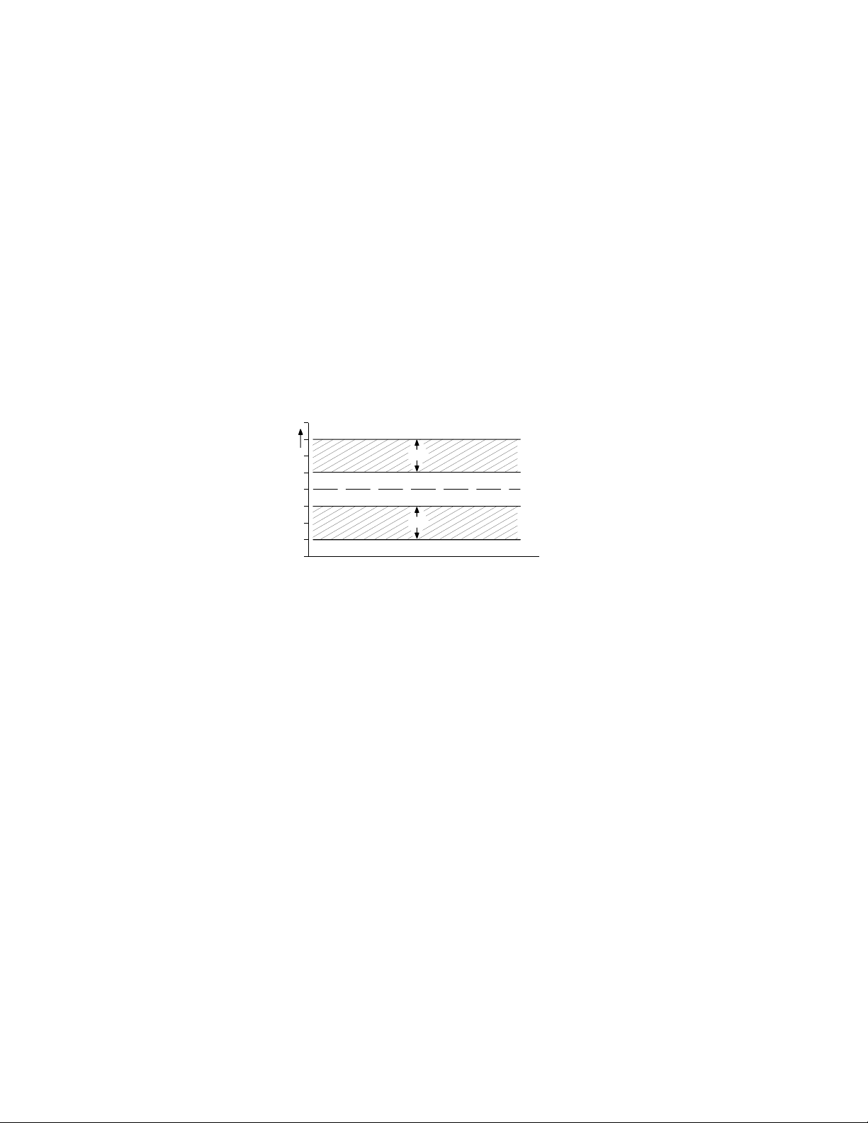
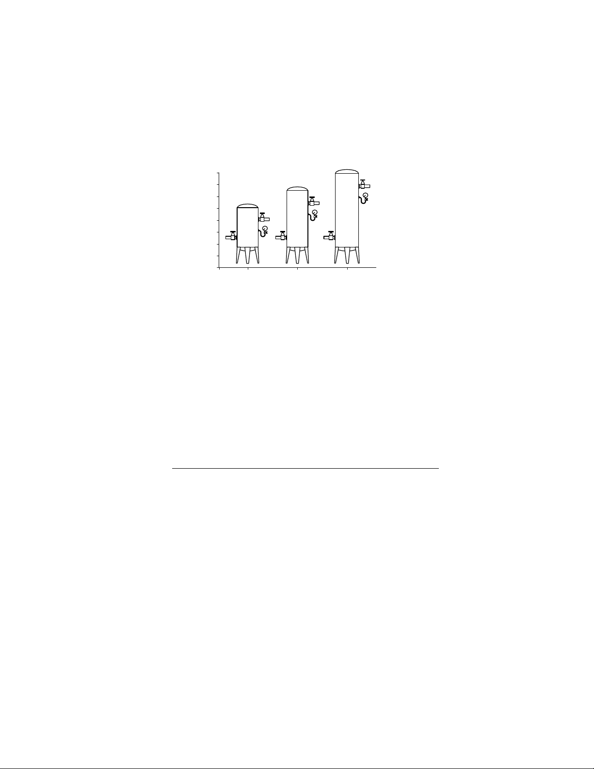
SYSTEM VOLUME
-
+
Assorted Receiver Tanks
System volume defines how fast system pressure will rise or fall in reaction to either increased/decreased demand or
increased/decreased supply. The larger the system volume, the slower the pressure changes in relation to
increased/decreased demand or supply. Adequate system volume enables effective pressure control and avoids system
over-pressurization in response to abrupt pressure fluctuations. Adequate system volume is created by correctly sizing and
utilizing air receivers.
The most accurate way to determine the size of air receivers or the additional volume required would be to measure the
size and duration of the largest demand event that occurs in the system, then size the volume large enough to ride
through the event with an acceptable decrease in system pressure. Sizing the volume for the worst event will ensure
system stability and effective control over all other normal operating conditions.
If measurement is not available, then estimating the largest event is a reasonable alternative. For example, assume that the
largest demand event could be equal to the loss of the largest operating air compressor. System volume would be sized to
allow time for a back-up compressor to be started and loaded with an acceptable decrease.
The following formula determines the recommended minimum storage volume for a compressed air system:
V “volume required” = T “time of the event” (C “demand” x Pa “atmospheric pressure”)
Delta P “pressure drop”
3
Example: T=15 Seconds (.25 minute), C=92 ft
4 - 25 hp compressors at 92 CFM (2.6 m
, Pa = 14.5 PSI (1bar), Delta P = 5 PSI
3
) each / 15 seconds to start and load a compressor.
V = [.25 x (92 x 14.5)]/5
V = (.25 x 1334)/5
V = 333.5/5
V = 67
Gal = 67 x 7.48
Gal = 498.9
14
Page 15
STANDARD SEQUENCE CONTROL STRATEGY
The standard configuration of the X4I provides FILO (First In/Last Out) sequence control strategy.
The sequence control strategy consists of two components:
• The compressor rotation strategy
• The compressor load control strategy
The rotation strategy defines how the compressors are arranged in a new sequence whenever a rotation event occurs.
Rotation events are triggered by a periodic rotation based on a set interval, a set time of day each day, or a set time of day
once a week.
The compressor load control strategy defines when compressors load and unload based on system pressure variations
and whether they run in fixed or variable speed modes.
Each compressor in a system will be assigned a permanent number based on where they are wired into the terminal PCB.
Compressor 1 will always be wired into terminal X01; compressor 2 will always be wired into terminal X02, etc.
Each compressor will also be assigned a letter from A to D based on its location in the sequence:
• A = the base load compressor (the first compressor to be used).
• B = the first trim compressor (the second compressor to be used).
• C = the second trim compressor (the third compressor to be used).
• D = the third trim compressor (the last compressor to be used).
Compressor sequence assignments are reviewed and dynamically changed at a rotation event based on the sequencing
strategy that is selected.
FIRST IN LAST OUT MODE (FILO)
The default configuration of the X4I provides FILO (First In/Last Out) sequence control strategy.
The primary function of FILO (First In/Last Out) mode is to efficiently operate a compressed air system consisting of
fixed speed compressors. The standard FILO rotation assignments can be modified using priority settings, which are
explained later in this section.
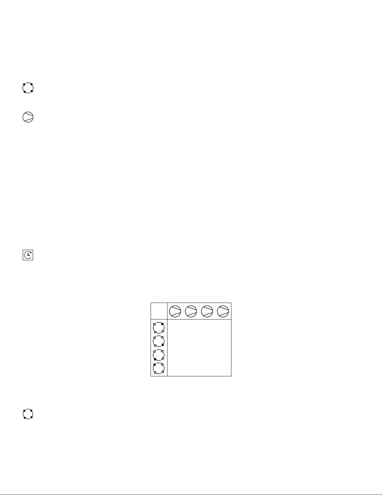
Whenever a rotation event occurs, the sequence assignment for each compressor is rearranged. The compressor that was
assigned as the base load compressor (A) is reassigned to third trim compressor (D) and all other compressors are
incremented by one.
1 2 3 4
#1
ABCD
#2
DABC
#3
CDAB
#4
BCDA
Sequence Rotation Table
SEQUENCE ROTATION EVENTS
A sequence rotation event can be triggered in the following ways: a periodic interval, a pre-determined time each
day, or a pre-determined time day and time each week.
Please refer to the Quick Setup Manual to determine how to configure the rotation events.
15
Page 16

ADVANCED CONTROL FEATURES AND FUNCTIONS
ADVANCED SEQUENCE CONTROL STRATEGIES
The advanced configuration of the X4I provides VEC (Variable Energy Control) sequence control strategy, priority settings,
table selection, and pre-fill operation.
VARIABLE ENERGY CONTROL MODE (VEC)
The primary function of VEC mode is to accommodate a variable speed compressor connected to the X4I using an
IRV-PCB interface.
VEC mode utilizes the FILO sequencing and rotation strategy with the additional control philosophy needed to efficiently
control variable speed compressors.
In any set rotation sequence, the variable speed compressor that is assigned closest to A will be utilized in trim mode and
will be allowed to throttle based on its local target pressure setpoint and the variations in system pressure. Any other
variable speed compressors in the system will be held in fixed speed mode to prevent multiple variable speed compressors
from oscillating.
The compressor that is allowed to run in variable speed mode will be evaluated at each rotation event.
Compressors are brought on or offline in response to changing demand using the FILO strategy. The base load compressor
(A) will be brought online first in the case of system pressure dropping below the low pressure setpoint. If pressure
continues to drop, the first trim compressor (B) will also load. Compressors C and D will load in that order if needed. When
system pressure rises above the high pressure setpoint, the last compressor to load will now be the first to be unloaded.
Compressors C, B, and A will be unloaded, in that order, if system pressure continues to increase.
Compressor A will always be the first to be loaded and last to be unloaded.
PRIORITY SETTINGS
The sequence assignment pattern can be modified by using the priority settings.
Priority settings can be used to modify the rotation sequence assignments. Compressors can be assigned a priority of 1 to
4, where 1 is the highest priority. Any compressor can be assigned any priority and any number of compressors can share
the same priority.
Priorities allow you to set up rotation groups. All compressors that have the same priority number will rotate inside their
own group. The group with the highest priority will always be in the front of the sequence.
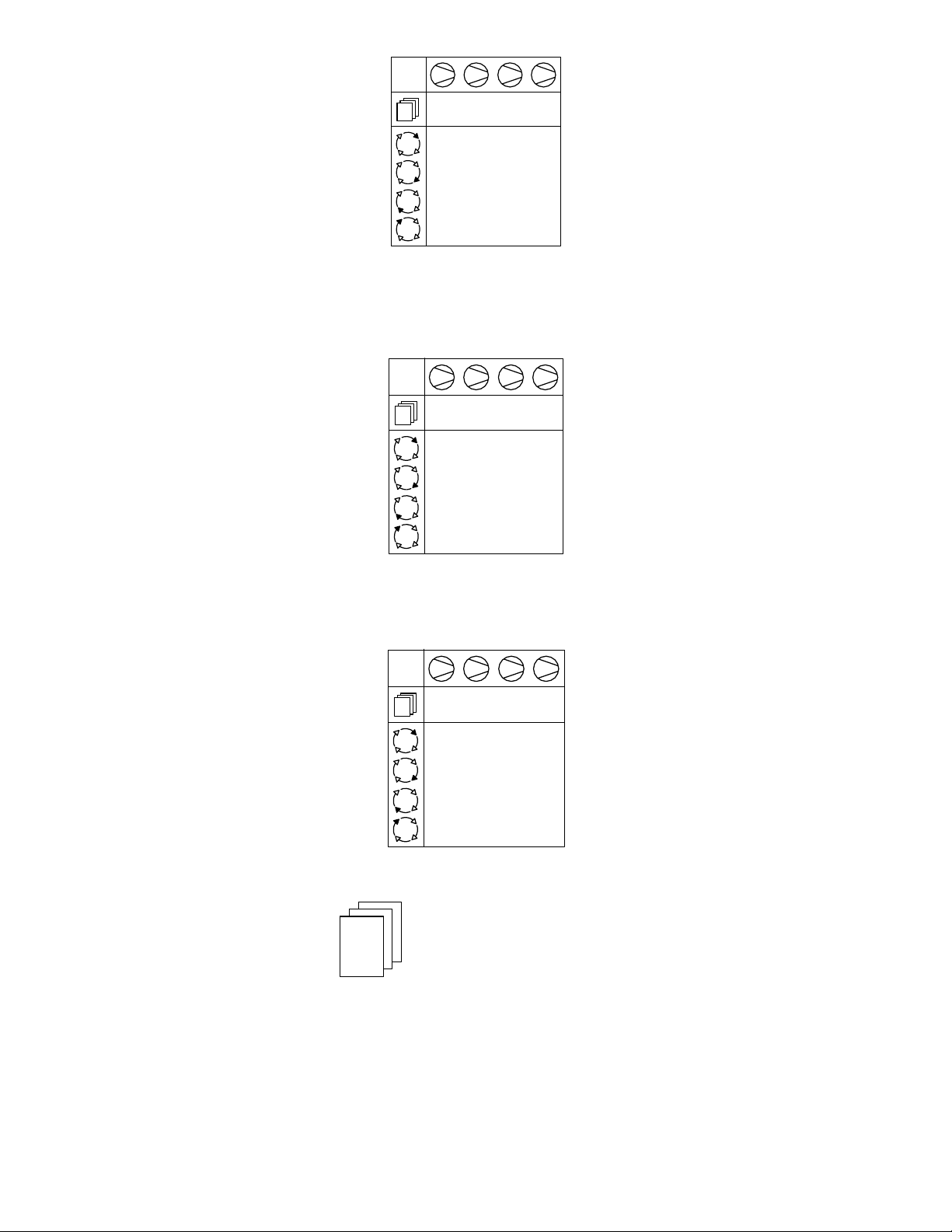
For example, in a four compressor system including one variable speed compressor in the compressor 1 position you may
want the variable speed compressor to always be in the base load position. By assigning compressor 1 a priority of 1 and
the other three compressors a priority of 2, the variable speed compressor will always remain at the front of the sequence:
1 2 3 4
1222
#1
ABCD
#2
ACDB
#3
ADBC
#4
ABCD
Compressor 1 has priority 1, all other compressors have priority 2
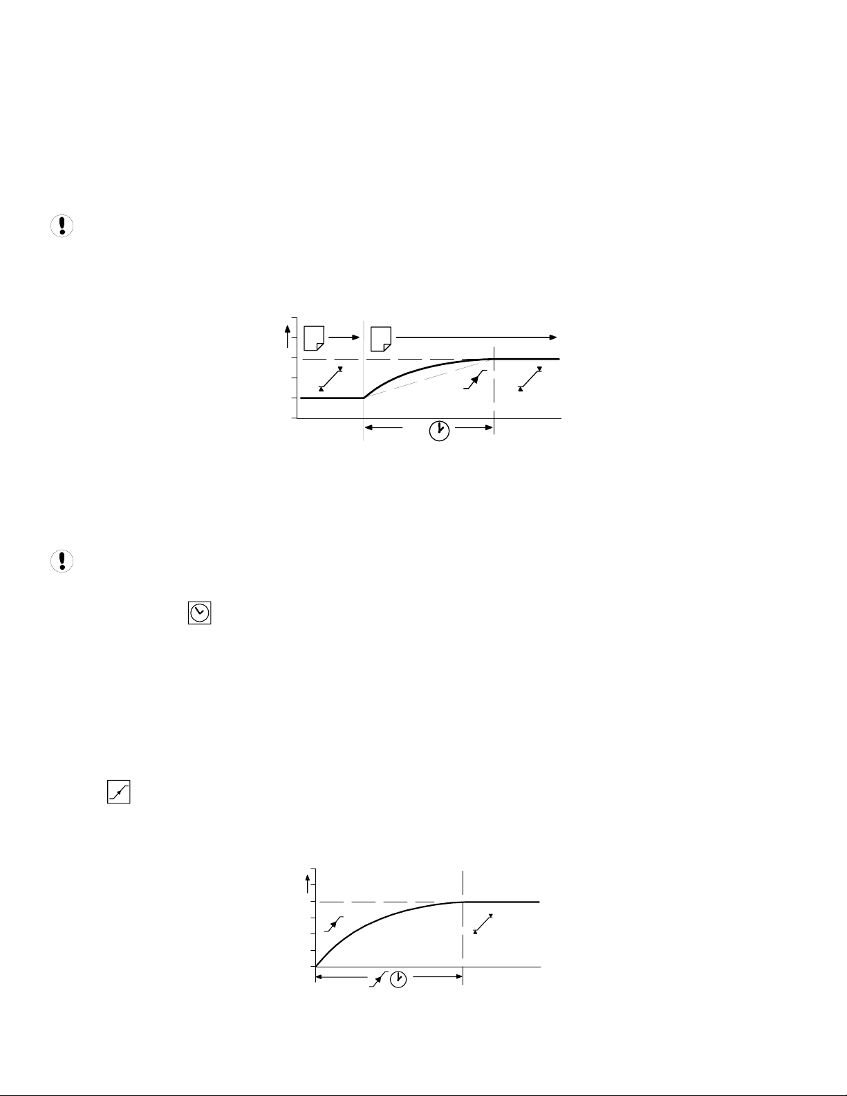
In another example, there is a four compressor system that includes a compressor in the compressor 4 spot that is used
only as an emergency backup compressor. To accomplish this, simply assign compressor 4 a lower priority than any other
compressor in the system:
16
Page 17
1 2 3 4
1112
#1
ABCD
#2
BCAD
#3
CABD
#4
ABCD
Compressor 4 has priority 2, all other compressors have priority 1
In a third example, there is a four compressor system that includes a variable speed compressor designated compressor 1
and a fixed speed compressor that is an emergency backup assigned as compressor 4. To ensure that compressor 1 is
always at the front of the sequence and compressor 4 is always at the end of the sequence, set the priority as shown
below:
1 2 3 4
1223
#1
ABCD
#2
ACBD
#3
ABCD
#4
ACBD
Compressor 1 has priority 1, compressor 4 has priority 3 and all other compressors have priority 2
A last example involves another four compressor system that will be assigned into two independently rotation groups.
Compressors 1 and 2 are given priority 1 and compressors 3 and 4 are given priority 2. This results in the rotation
sequence shown below:
1 2 3 4
1122
#1
ABCD
#2
BADC
#3
ABCD
#4
BADC
Two independently rotating compressor groups
T01
PH
- - - -
PL
- - - -
Pm
- - - -
SQ
TABLES AND THE PRESSURE SCHEDULE
- - - -
The X4I operates based on settings that are configured into one of three tables. Each table defines the operational settings
and sequence control mode of the X4I. The X4I can be instructed to change among the tables at any time based on the
configuration of the pressure schedule.
This functionality allows the X4I to switch among multiple different system configurations without any disruption to
control. This is particularly useful in the case of shift changes, or weekends when the system is to be deactivated.
Each table consists of the following parameters which can be set independently in each table:
• PH – High Pressure Setpoint
17
Page 18
• PL – Low Pressure Setpoint
• Pm – Minimum pressure warning level
• SQ – Sequence Rotation Strategy
• 01 – Compressor 1 Priority
• 02 – Compressor 2 Priority
• 03 – Compressor 3 Priority
• 04 – Compressor 4 Priority
The “maximum” pressure fault level and the rotation interval, or rotation time, are set independently in a
configuration menu and are unchanging regardless of the table selected.
When the X4I is instructed to change between tables, it will not abruptly change the system operating parameters. The X4I
will adjust the system target pressure upward or downward to the next table’s settings. This transition will occur gradually
to preserve energy efficiency and safe, reliable control:
1
The time the system is allotted to change the target pressure is known as the Pressure Change Time (PC). This is a value
that is adjustable in the system settings screen. See the Quick Setup Manual.
If the X4I is able to complete the transition in less time than is allotted without threatening energy efficiency then PC will
be automatically shortened.
An aggressively short time setting will compromise energy efficiency.
PRESSURE SCHEDULE
The X4I is equipped with a real-time clock feature and pressure schedule functionality. The pressure schedule function can
be used to provide system automation.
The pressure schedule consists of 28 individual settings that instruct the system to change from one table to another, or
put the system into standby mode dependent on the time of day and the day of the week. The pressure schedule will cycle
from 00:00 hours Monday (day #1) to 23:59 hours on Sunday (day #7) each calendar week.
The pressure schedule has the capability of changing tables based on the time of day, once each day, and once each day
except weekends. Please see the Quick Setup Manual for detailed information on how to configure the pressure schedule.
2
PC
Changing Target Pressures
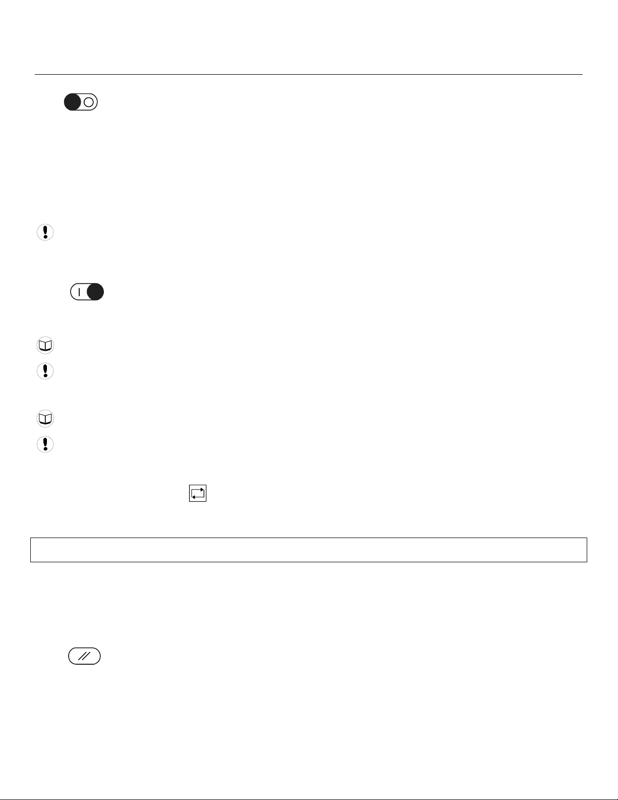
PRE-FILL
The pre-fill feature provides an energy efficient method of increasing pressure to normal operating levels upon system
start. This feature avoids the inefficient potential for all compressors to start and load in an attempt to quickly get the
system pressure up to normal levels:
18
System pressure during pre-fill
Page 19

At system start (manual start or automated start from standby), the X4I will only load compressors that have been pre-set
for pre-fill operation, for a pre-set period of time. The pre-fill time (PT) can be adjusted to suit system characteristics. The
aim is to increase pressure to normal operational levels, using only the pre-determined compressors, prior to the pre-fill
time expiring.
If normal operational pressure is reached prior to the set pre-fill time, the pre-fill function will automatically cease and
normal operational control will begin. If normal operational pressure is not reached by the end of the pre-fill time, the X4I
will utilize as many available compressors as required to achieve normal operational pressure as quickly as possible.
Normal operational control will then begin.
Two pre-fill modes are available. Both function in the same way but differ in response to a failure, or loss, of a pre-fill
compressor.
•
Backup Mode: Compressor(s) can be pre-selected as “primary pre-fill” compressor(s) or “backup
pre-fill” compressor(s). If a primary pre-fill compressor experiences a shutdown, or is stopped, it is
replaced by a pre-defined backup compressor and pre-fill continues.
•
To manually skip pre-fill mode, press and hold START for several seconds.
! X
Standard Mode: If one or more of the pre-defined pre-fill compressors experiences a shutdown,
or is stopped, the pre-fill function is cancelled and normal operation begins.
19
Page 20

ALTERNATE CONTROL FEATURES AND FUNCTIONS
The alternate configuration of the X4I provides EHR (Equal Hours Run) and FIFO (First In/First Out) sequence control
strategy.
EQUAL HOURS RUN MODE
The primary function of EHR mode is to keep the running hours of all compressors in the system as close as possible.
This provides the opportunity to service all of the compressors at the same time, given that the expected service interval
for the compressors is similar.
EHR is not an energy efficient focused mode of operation.
Each time a rotation event occurs, the compressor sequence is examined and will be rearranged based on the running
hours recorded for each compressor. The compressor with the fewest running hours is assigned as the base load
compressor and the compressor with the most running hours is assigned as the third trim compressor. For systems with
more than two compressors, the compressors will be assigned from A to D in accordance with increasing running hours.
Example: The compressors in a four compressor system have the following recorded running hours when a rotation event
occurs:
• Compressor 1 = 2200 hours
• Compressor 2 = 2150 hours
• Compressor 3 = 2020 hours
• Compressor 4 = 2180 hours
The new sequence order after the rotation event would be:
• Compressor 1 = D
• Compressor 2 = B
• Compressor 3 = A
• Compressor 4 = C
Compressor 3, which has the fewest running hours, will now be utilized more frequently in the new sequence, allowing
running hours to accumulate at a faster rate.
The X4I continuously monitors the running status of each compressor and calculates the accumulated running hours.
These readings are viewable and adjustable in the X4I C01 setting screens. The X4I will use these values during EHR mode.
The running hours on the X4I should be routinely checked to see that they match the compressors’ local calculations, and
adjusted if necessary.
If a compressor is operated independently from the X4I, the running hours record may not be accurately updated.
The running hours meter display on most compressors are intended for approximate service interval indication only
and may deviate in accuracy over a period of time.
Compressors will be utilized following the FILO strategy.
FIRST IN FIRST OUT MODE (FIFO)
The primary function of FIFO mode is to keep a compressor loaded for the longest amount of time possible in order
to minimize starts and stops on the motor. The compressors will continuously share pressure regulation.
FIFO is not an energy efficient focused mode of operation.
FIFO does not follow sequence rotation events. Compressors are rotated each time a compressor is loaded. The rotation
strategy becomes the control strategy using the control mode.
When system pressure drops below the low pressure setpoint, compressor 1 (A) will be the first to load as usual. If system
pressure continues to decrease, compressor 2 (B) will be loaded and be reassigned to (A) while compressor 1 is reassigned
20
Page 21

as (D). If this causes system pressure to rise above the high pressure setpoint, then compressor 1 (D) will be unloaded to
allow compressor 2 (A) to maximize its run time. If system pressure decreases further, compressor 3 will be loaded and
reassigned to (A) while Compressor 2 is reassigned to (D) and so on.
The most recently loaded compressor will always be assigned (A) and the longest running compressor will always be
assigned (D).
1
2
3
4
ABCD DABC DABC CDAB BCDA BCDA ABCDBCDA
FIFO Rotation
21
Page 22

SECTION 7 — INSTALLATION
It is recommended that installation and commissioning be carried out by an authorized and trained product supplier.
UNIT LOCATION
The X4I can be mounted on a wall using conventional bolts. The X4I can be located remotely from the compressors as long
as it is within 330 feet (100 meters) of cable length. The X4I must also be located within 330 feet (100 meters) of the
system pressure transducer.
POWER SUPPLY
A fused switching isolator must be installed to the main incoming power supply, external to the X4I. The isolator must be
fitted with a properly sized fuse to provide adequate protection to the power supply cable used (in accordance with local
electrical and safety regulations).
1234
N
L
EE
X01
LNE
XPM-TAC24
X04
VOLTAGE SELECT
X04
VOLTAGE SELECT
1
234
1
234
230Vac
115Vac
Power Supply Terminals
Ensure that the voltage select input is properly jumpered for the incoming power.
PRESSURE SENSOR LOCATION
The system pressure sensor (P) must be located where it will see the air pressure that is common to all of the compressors.
GENERATION SIDE PRESSURE CONTROL
P
1
P
2
Pressure Sensor Located Before Cleanup Equipment
Demand side pressure will be lower than the system pressure due to pressure differential losses across air treatment
equipment. The nominal system pressure will reduce as the air treatment differential pressure increases.
22
Page 23
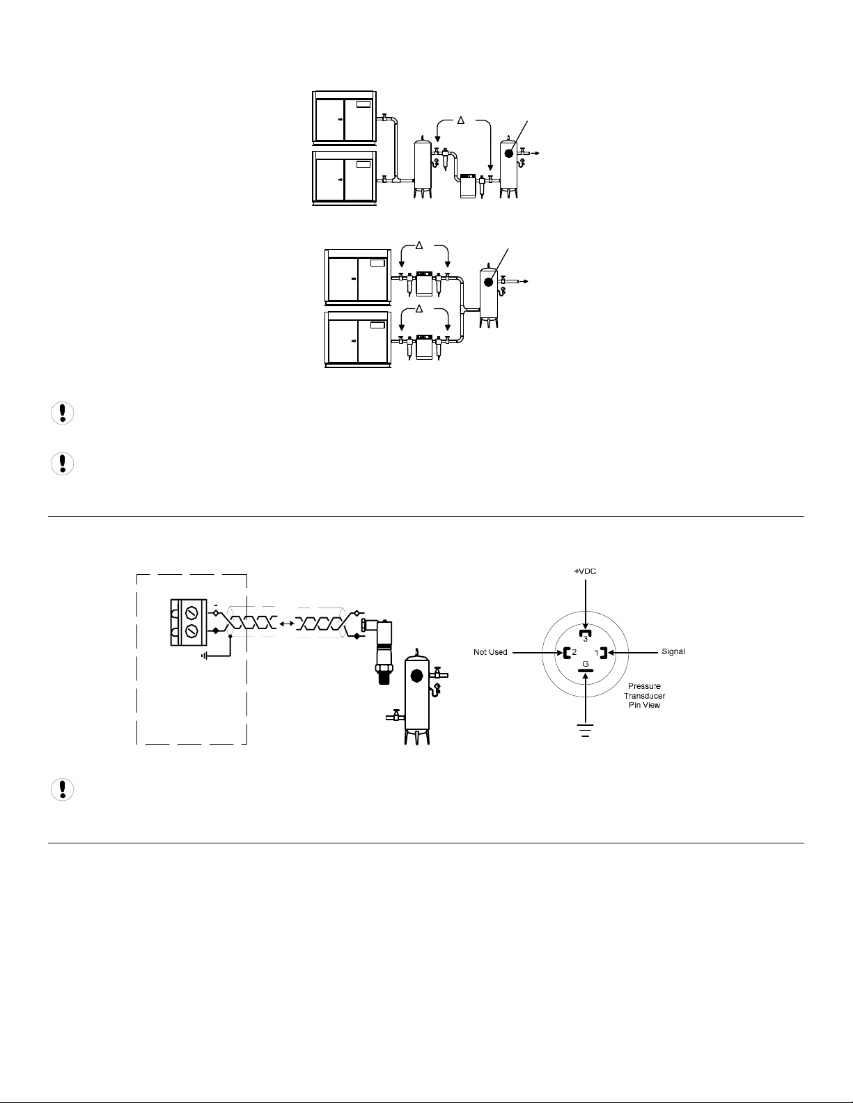
SYSTEM (DEMAND SIDE) PRESSURE CONTROL
1
P
P
2
Pressure Sensor Located After Shared Cleanup Equipment
P
P
1
P
2
Pressure Sensor Located After Individual Cleanup Equipment
Ensure each compressor is equipped with independent excess pressure shutdown. An increase in pressure differential
across air treatment equipment can result in excess compressor discharge pressure.
Regular routine monitoring of pressure differential across air treatment equipment is recommended.
PRESSURE SENSOR CONNECTION
The pressure sensor connects to terminal X05 of the X4I terminal PCB using a shielded 18 AWG maximum 2-conductor
cable no more than 330 feet (100 meters) in length.
X05
26
25
Wire polarity is important.
+
Pressure Sensor Wiring and Location
-
+
4-20mA
IR-PCB INTERFACE MODULE
The IR-PCB is designed to interface a compressor with the X4I using a 7-conductor shielded cable no greater than 330 feet
(100 meters) in length.
Each compressor in the system must be assigned a unique identification number from 1 up to the number of compressors
in the system. The identification number should be clearly indicated on each compressor for operational reference.
For each compressor utilizing an IR-PCB, connection to the X4I the signal wires must be made to the correct X4I terminals
for that compressor number. Compressor 1 should be wired to terminal X01 on the terminal PCB, Compressor 2 should be
wired to terminal X02 on the terminal PCB, etc.
23
Page 24

IR-PCB Interface Module
The IR-PCB is a DIN rail mountable module designed to be installed within the compressor starter enclosure.
Each air compressor must be equipped with a load/unload regulation system and, if not regulated with a single electromechanical pressure switch, have a facility for a remote load/unload control with the ability to accept a volt-free switching
contact input for remote load/unload.
V
For variable speed compressor(s) equipped with a “variable/fixed” digital input function, install a 7-conductor shielded
cable from the IR-PCB to the X4I.
Consult the air compressor manual or your air compressor supplier/specialist for details before installing the X4I.
Each air compressor must be equipped with an online/offline pressure regulation system capable of accepting a remote
load/unload signal through a volt free switching contact or a single electro-mechanical pressure switch.
The IR-PCB accepts a 12V to 250V input voltage detection system and utilizes universal relay contact control outputs (250V
“CE” / 115V “UL” @ 5A maximum) integrated directly into the circuits of an air compressor. The IR-PCB avoids the need for
additional relays or remote inputs. The IR-PCB also acts as an electrical barrier between the compressor and the X4I
providing protection and voltage isolation.
INPUT FUNCTIONS
The IR-PCB is fitted with a six-pin terminal, C04, for compressor monitoring. The IR-PCB uses two inputs, Ready and Run, to
determine compressor status. An alarm input can be used if compressor warning indication is available and required. The
alarm input is optional and is not necessary for system operation.
READY INPUT
The ‘Ready’ connection is intended to indicate that the compressor is in a “started” state, has no alarm condition that has
shut down the compressor, and is ready to respond to X4I regulation without manual intervention.
24
Page 25

+V
READY LAMP
ALARM
RUN
C04
READY
0V
Typical Ready Input Wiring
The READY input will accept 12V to 250V ac (50/60Hz) or dc.
Do not connect a voltage greater than 250Vac/dc to this input.
This input must be connected to a circuit of the compressor control system that will be energized when the compressor is
in a started (standby or running) condition. For example, locate the circuit across the ready or operating lamp as shown.
The voltage to this input must de-energize when the compressor is stopped and unavailable to produce air upon a load
signal, or the emergency stop button is pressed, or when the compressor experiences a fault that prevents the compressor
from running.
When the compressor ready lamp or other control circuit is energized, the IR-PCB will detect the voltage and signal the X4I
that the compressor is ready and available to load and produce air when a load request signal is given.
The IR-PCB common input terminal must always be connected to the neutral, common or 0V line of the applied input
voltage.
READY INPUT, ALTERNATIVE CONNECTION METHOD
In instances where a convenient voltage signal for a compressor ready condition is not available, the “ready” input can be
connected directly to a constant compressor control voltage (12V to 250Vac or dc). This will signal the X4I that the
compressor is ready and available at all times when power is applied to the compressor. The X4I has a built-in function to
determine when a compressor is not responding, or is in a shutdown condition, even if the “ready” signal says otherwise. If
the X4I requests a compressor to run/load, but fails to detect a RUN signal within 60 seconds, the X4I will regard the
compressor as “not ready” and indicate the compressor as not available. If a RUN signal is reacquired at any time, the X4I
will automatically reset the compressor “not ready” condition and re-establish control.
+Vac
F1
0Vac
READY
Alternative Ready Signal Connection
Never connect the “Ready” input positive voltage connection directly to the output of a control system transformer.
Always connect after a fuse or circuit breaker.
If a normally closed contact of an emergency stop button is included in the compressor power supply circuit, connect after
the emergency stop button contacts. This will instantly indicate a compressor “not ready” condition if the emergency stop
button is activated.
25
Page 26

RUN INPUT
MAIN (LINE) CONTACTOR
0V
+V
READY
ALARM
RUN
C04
Run Signal Circuit
The RUN input will accept 12V to 250V AC (50/60Hz) only. DC cannot be used.
Do not connect a voltage greater than 250V to this input.
12V to 250Vac must be applied to the “run” terminals when the compressor motor is running.
This input can be connected to the control terminals A1 and A2 (coil) of the main starter contactor of the compressor.
When the compressor control system energizes the main contactor, the IR-PCB will detect the voltage across the contactor
coil terminals and signal the X4I that the compressor is running.
Alternatively, if the main contactor coil voltage is greater than 250Vac, a contactor auxiliary switch can be used to apply a
suitable voltage to the “run” input terminals.
MAIN (LINE) CONTACTOR
+V
+V
AUXILIARY SWITCH
ALARM
RUN
C04
READY
0V
0V
Run Signal Circuit with Auxiliary Switch
In instances where a motor starter contactor is not available or accessible, any part of a compressor control circuit that is
energized when the compressor is running can be monitored. For example: fan contactor or voltage signal to a remote
starter.
The IR-PCB input common terminal must always be connected to the neutral, common or 0V line of the applied input
voltage.
26
Page 27

WARNING INPUT (OPTIONAL)
The IR-PCB is equipped with a warning input that can be used to detect warning conditions.
An alarm that stops the compressor, and/or prevents the compressor from running is determined from the “run” and
“ready” inputs. Warning detection is optional and is not a requirement.
Alarm Lamp
+V
0V
Alarm Run Ready
C04
Warning Input Circuit
The warning input will accept 12V to 250V AC (50/60Hz) or DC.
Do not connect a voltage greater than 250Vac/DC to this input.
This input can be connected to the terminals of an alarm lamp or other accessible part of the control circuit that is
energized when the compressor is in a warning condition.
If a warning condition is experienced the compressor warning lamp, or warning circuit, will energize. The IR-PCB will detect
the voltage and signal the X4I that a warning has occurred. If the compressor has no accessible warning circuit, or this
function is not required, the IR-PCB alarm terminals can be ignored.
The IR-PCB input common terminal must always be connected to the neutral, common or 0V line of the applied input
voltage.
OUTPUT FUNCTIONS
The X4I will control the IR-PCB load/unload relay outputs based on the active system load and unload pressure setpoints.
The IR-PCB load/unload relay contacts can be used for compressor controllers that have electro-mechanical pressure switch
load/unload regulation.
27
Page 28

OUT
NO
VFD/Fixed
OUT
OUT
NC
IN
1
4
C
2
3
NO
+VDC
Local/Remote
Load/Unload
IN
NC
IN
C
VFD
Relay
4
SEQ
Relay
1&2
LOAD
Relay
3
C03
VFD
SEQ
CONT
LOAD
UNL
GND
+20VDI2DI1
135V246
24Vac
IR-PCB Internal Output Circuits
The C01 and C02 terminals of the IR-PCB are intended to control load and unload regulation of the compressor.
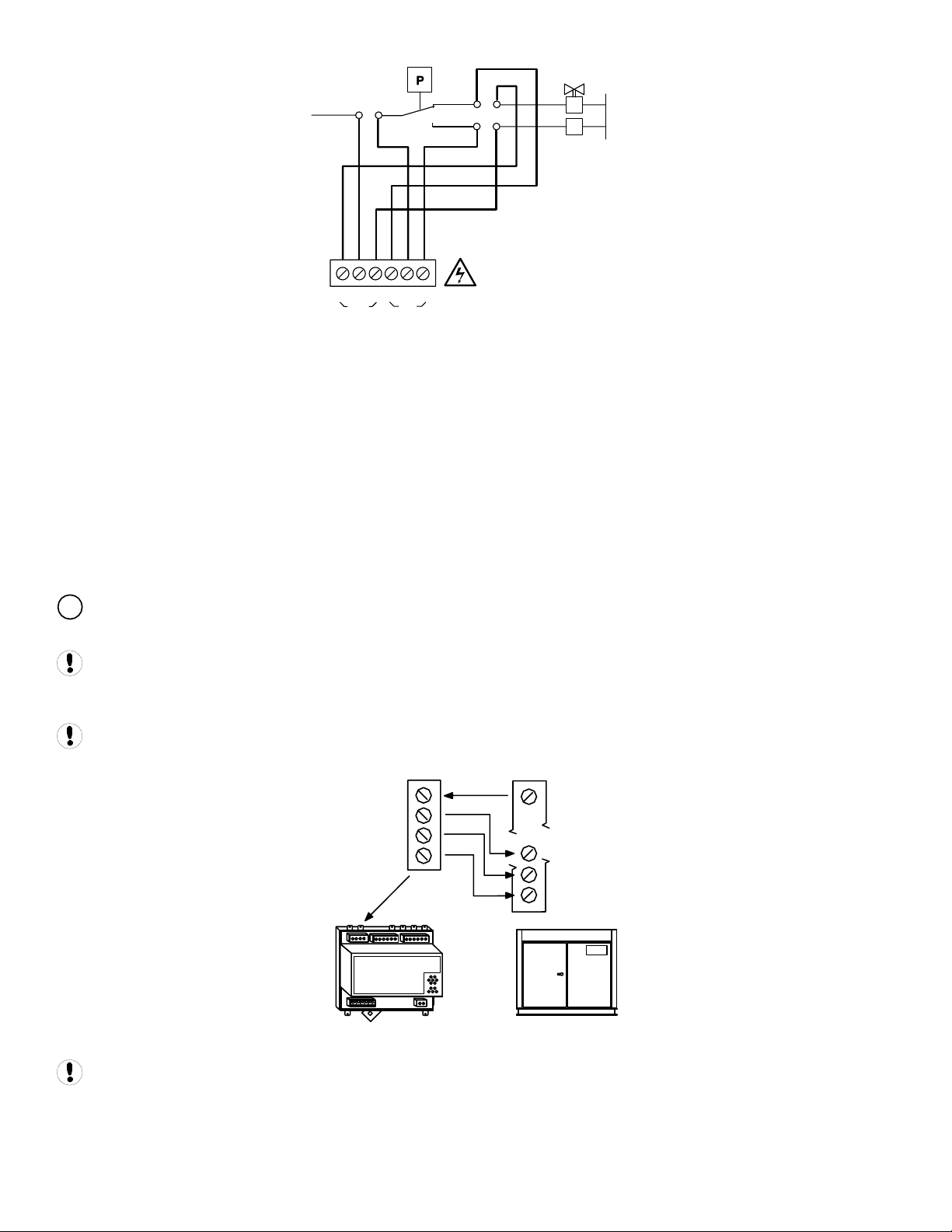
PRESSURE SWITCH REGULATION
For air compressors fitted with an electro-mechanical pressure switch, a six-pin terminal C02 has been provided to enable
connection to a pressure switch that has a two-wire or three-wire connection.
When connected, the pressure switch can be switched in and out of circuit automatically. If the X4I is stopped or
experiences a failure or loss of power, pressure control will automatically revert back to the pressure switch and the
compressor will continue to operate in “local” mode.
The local pressure settings of all compressors in the system should be set in a cascaded manner such that the system
will operate normally in the event of X4I inoperability.
The NC (normally closed) and NO (normally open) terminal references of the IR-PCB are related to internal connection
functions and should not be referenced to the connections of a compressor pressure switch, which will generally be in
reverse order.
Lethal voltages may be present on the terminals of the air compressor pressure switch. Isolate the air compressor
power supply before starting any work.
0V
+V
LOAD
SOLENOID
C
C
C
O
N
N
OUT
C02
C
O
N
N
IN
Two Wire Pressure Switch Connections
28
Page 29
LOAD
SOLENOID
+V
RUN-ON
TIMER
CNC
C
C
OUT
N
C02
O
N
IN
O
N
0V
Three Wire Pressure Switch Connections
DIGITAL REGULATION CONTROL TERMINAL C01
A 4-pin connector, C01, has been provided for air compressor controllers fitted with digital inputs allowing remote
pressure regulation control.
This terminal provides volt free contact closure, referenced to a common terminal pin, for:
• Remote Load Enable (remote/local pressure regulation control)
• Remote Load (remote load/unload)
• Remote Variable Speed Regulation Inhibit (remote variable/fixed speed regulation control)
The “remote load enable” function provides the facility to change the compressor load regulation from internal control to a
remote switching source (local/remote).
V
The “remote variable/fixed” function provides for multiple variable speed compressor regulation control on variable
speed compressor(s) equipped with this facility.
When using the “Variable/Fixed” function, the “V” terminal of the IR-PCB must be connected to the appropriate “V”
terminal of the X4I (according to compressor number) with an additional wire. Use a 7-conductor shielded cable in this
instance.
Compressors that use electronic pressure detection but are not equipped with a remote pressure control enable
feature will not automatically revert to local control if the X4I is stopped or experiences a fault or loss of power.
+VDC
VFD/Fixed
Load Enable
Load/Unload
+VDC
VFD/Fixed
Load Enable
Load/Unload
ir-PCB
Load, Sequence, and VFD Connections
Compressor controller inputs common voltage may be 0V or +V.
The local/remote pressure regulation input and/or remote load input logic of some electronic pressure sensor type
controllers are reversed. In this instance, the “pressure switch” outputs (terminal C02) can be used to establish alternative
logic control connections.
29
Page 30

For Example:
If the compressor controller “Local/Remote Pressure Control” input is a normally open type (local when open, remote when
closed), but the “Remote Load” input is a normally closed type (load when open), the IR-PCB pressure switch terminal
contacts can be used to achieve the correct switching logic.
C02
OUT
NO
C
NC
NO
IN
C
NC
Local/Remote
common
Remote Load
common
Alternate Logic
Examine the “i-PCB” internal output circuit diagram to establish any desired switching logic that may differ from normal
practice.
Do not attempt to utilize “Digital Pressure Regulation Control” (terminal C01) and the “Pressure Switch Control”
(terminal C02) output connections at the same time for different products. These two output functions are internally
connected and a short circuit condition and/or malfunction may result.
The IR-PCB connection examples shown in this manual are intended to provide a guide for the majority of compressor
control systems in use. Some compressors have variations in operation and/or function; consult your compressor
supplier/specialist for advice.
SERVICE MAINTENANCE SWITCH
The IR-PCB is equipped with a volt-free input (terminal C05) that can be used to remove the compressor from X4I control,
without generating a fault condition, during short-term maintenance or servicing periods.
1
C05
2
Service Maintenance Switch Circuit
When the “Service Maintenance Switch” input terminal pins are connected together using a volt-free switching contact, the
X4I will indicate that the compressor is not available but will not generate a warning, alarm, or shutdown condition. The
X4I will also remove the compressor from the sequence strategy and substitute with an alternative available compressor if
necessary. When the “Service Maintenance Switch” input circuit is open again, the compressor will automatically be
accepted back in to the sequence strategy and will be utilized when next required.
The use of a “key switch” is recommended for this purpose in order to prevent the switch contacts being inadvertently left
in the closed circuit condition after service maintenance is complete.
DO NOT connect any external voltage source to the pins of terminal C05.
AUXILIARY INPUT (OPTION)
The X4I is equipped with an auxiliary input at terminals 31 and 32 (X07).
The function of the input is menu selectable and can be adapted for differing application requirements.
X07
32
31
30
Page 31
Auxiliary Input Circuit
The input is designed to detect a remote “volt-free” switching contact (rated for a minimum 24VDC @ 10mA).
AUXILIARY OUTPUT (OPTION)
The X4I is equipped with a remote relay contact output at terminals 33 and 34 (X08).
The function of the output is menu selectable and can be adapted for differing application requirements.
X08
R6
34
33
Auxiliary Output Circuit
The remote output relay contacts are rated for 240V “CE” / 115V “UL” @ 5A maximum.
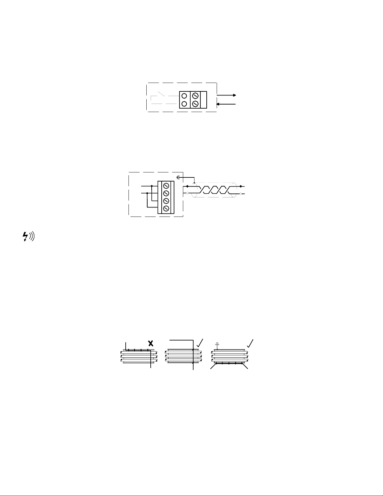
RS485 COMMUNICATIONS
The X4I is equipped with an RS485 network communications capability using the Multi485 protocol. This can be used for
remote connectivity to optional networked units and modules with Multi485 communications capabilities.
X06
L1
L2
30
29
28
27
L1
L2
RS485
RS-485 Connection Circuit
RS485 data communications and other low voltage signals can be subject to electrical interference. This potential can
result in intermittent malfunction or anomaly that is difficult to diagnose. To avoid this possibility, always use shielded
cables, securely bonded to a known ground at one end. In addition, give careful consideration to cable routing during
installation.
• Never route an RS485 data communications or low voltage signal cable alongside a high voltage or 3-
phase power supply cable. If it is necessary to cross the path of a power supply cable(s), always cross at a
right angle.
• If it is necessary to follow the route of power supply cables for a short distance (for example: from a
compressor to a wall along a suspended cable tray), attach the RS485 or signal cable on the outside of a
grounded cable tray such that the cable tray forms a grounded electrical interference shield.
• Where possible, never route an RS485 or signal cable near to equipment or devices that may be a source
of electrical interference. For example: 3-phase power supply transformer, high voltage switchgear unit,
frequency inverter drive module, radio communications antenna.
31
Page 32

SECTION 8 — FAULT CODES
In the event of a unit or system “fault” the X4I will display a fault code. The fault code becomes an item in the user
operational display menu. If more than one “active” fault occurs, each will be displayed as a separate item in the
operational user menu. Press UP or DOWN to view all active fault codes or to view the normal status display.
Alarm (Warning)
Shutdown (Trip)
Fault codes are separated into unit faults (ERR) and system alarms (warning) (SYS).
Each fault type has a unique numeric code.
ERR.01
ERR.04
ERR.05 Emergency Stop
ERR.06
SYS.01
SYS.02
SYS.04
Compressor fault states are displayed as part of the normal operational status display and do not generate fault
codes. Examine the applicable compressor unit to establish the nature or description of the detected fault condition.
Pressure Sensor
Internal 24V Fault
Real Time Clock Error
Excess Pressure (PM)
Min Pressure (Pm)
Insufficient Capacity
X4I COMPRESSOR FAULT INDICATIONS, TYPES, AND CODES:
Compressor fault conditions are displayed on the user compressor status screen and are not regarded as X4I unit fault
conditions.
Compressor fault conditions are displayed symbolically on the main User compressor status screen.
ALARM (WARNING)
• The Alarm input on the “ir-PCB” has been activated.
• The compressor, or remote compressor interface unit, is reporting a general or group alarm condition on
the RS485 network (RS485 network connectivity only).
The X4I fault LED will “slow flash”.
The alarm (warning) symbol will alternate with the normal compressor status symbol every two seconds.
NOT AVAILABLE
The compressor is reporting a general or group trip (shutdown) condition. The compressor has been stopped and taken
out of service, power to the compressor has been isolated/lost or the compressor is not communicating.
• The ready input of the “ir-PCB” is no longer active.
• The run input of the “ir-PCB” is no longer active while the compressor is being requested to run loaded.
• The run input of the “ir-PCB” did not activate within 60 seconds of a load request.
• The compressor is reporting a general or group shutdown or stopped condition (RS485 network
connectivity only).
32
Page 33

• The remote compressor interface unit is in a shutdown condition (RS485 network connectivity only).
The X4I fault LED will “fast flash”.
The “not available” symbol will “slow flash”.
# COMPRESSOR INHIBITED, REMOVED FROM SERVICE
Set in the X4I active “table” (# = table number 1, 2 or 3) as inhibited from use.
In this condition, the status of the compressor is still monitored. The X4I fault LED will not illuminate or flash unless an
actual alarm (warning) or trip (shutdown, not available) condition occurs.
The two symbols will alternate every two seconds.
SERVICE/MAINTENANCE
Inhibited from use by the user using the “ir-PCB” service/maintenance function.
In this condition, compressor fault conditions are ignored. The X4I fault LED will not illuminate or flash.
COMMUNICATIONS DISRUPTION
Network communications with the compressor have been disrupted/lost.
Note: only applicable where the compressor is integrated with the X4I using the RS485 communications network.
SPECIAL CONTROLLER FAULT CODES
• E0836 PLL Unlock Internal failure or excessively high external electrical interference
• E0866 Controller internal power supply fault
• E5000 Internal memory map error
• E5001 Internal memory failure
ERROR LOG
E01
15
- : - - - . - -
01 E : ERR . 01
02
03
04
The error log is presented in chronological order. Entry 01 is the most recent, whereas entry 15 is the oldest. Each error
log item will show the error code. To view details for the selected error log item, press the ENTER
E01
01.01
- : - - - . - -
- : - - - . - -
- : - - - . - -
Error Log Screen
button.
E: ERR.01
16/05/2006 14:25
1
First Error Log Information Screen
33
Page 34

The first error information display shows:
• The error code
• Error code symbols (if applicable)
• The date the error occurred
• The time the error occurred
• The active operational functions of the X4I at the time the error occurred; (see: X4I Status Display for
Icons)
To view the second error information screen, press the ENTER
press the ESCAPE
button.
E01
01.01
button. To return to the main error log menu screen,
1 2 3 4
Second Error Log Information Screen
The operational status of each compressor, at the time the error occurred, is displayed symbolically. See Compressor
Status Displays for Icons.
To return to the first information screen press the ENTER
error log menu screen press the ESCAPE
button.
button or the ESCAPE button. To return to the main
34
Page 35

SECTION 9 — COMMISSIONING
When commissioning the X4I, carry out the following procedures before attempting to start.
It is recommended that an authorized and trained service technician perform the commissioning.
PHYSICAL CHECKS
1. Before applying power to the X4I, ensure the power supply connections are correct and secure and the operating
voltage selector is set correctly for the power supply voltage in use (115Vac or 230Vac (+-10%), 50/60Hz).
2. Open the front panel of the X4I and check the location of the link wire(s) connected to the “Voltage Selection”
terminals of the power supply PCB. If necessary, change the link wire locations to those illustrated for the voltage
in use.
See the section on Installation for more information.
3. Switch on the power supply to the X4I.
4. The control program identification will be displayed for a short period followed by the normal operational user
display.
PRESSURE DISPLAY
Check the displayed system pressure. If the pressure is incorrect, or inaccurate, check the type and range of the sensor
and carry out the pressure sensor commissioning and calibration procedure. If the display shows an error, this will need to
be corrected before continuing. See the Operator’s Manual for troubleshooting and correcting the fault/error condition.
X4I QUICK SET-UP CONFIGURATION
Before successful basic operation can be established specific parameters must be entered prior to startup. Please refer to
the X4I Quick Setup Manual for instruction to accomplish this.
35
Page 36

SECTION 10 — SYSTEM CONFIGURATION
ACCESSING THE X4I CONFIGURATION SCREENS
In order to change the configuration parameters you will first need to input the service access code. The service access
code is 0032. Enter this code as follows:
1. Press the MENU
2. Adjust the first access code digit by using the scroll up (+)
the correct number shows press the ENTER
right.
3. Adjust the remaining digits until the proper access code is shown on the screen. If for any reason you need to go
back to a previous digit press the escape
4. When you’ve adjusted the final digit to the correct number press the ENTER
animation of a key opening a lock. You are now able to access the configuration screens.
5. When in menu mode, if no button activity is detected for a period of time the access code is cancelled and the
display will automatically reset to the normal operational display
6. After successfully entering the access code you should see the screen shown below. The cursor will flash on the
button. This will display the Access Code Screen.
Access Code Screen
and scroll down (-) buttons. When
button. The cursor should then move to the next digit to the
button. This will back the cursor up one digit at a time.
button and you should see an
name of the current page (P00). You can scroll through the tabs by pressing the scroll up (+)
down (-)
36
buttons.
Default Configuration Screen
and scroll
Page 37

USER CONFIGURATION: TAB S01
1. Scroll up (+) or scroll down (-) until the S01 page is highlighted.
S01 Screen
2. Press the ENTER
REAL TIME CLOCK SETTINGS
1. From the S01 home screen scroll up (+)
(Real Time Clock).
button to confirm your selection. The cursor should be flashing on line 01 Ct.
User Configuration Home Screen
or scroll down (-) to move the cursor to highlight 01- Ct
Real Time Clock Setting
2. The default setting for this parameter is - --.--, which indicates the 24 Real Time Clock has not been initialized.
The format for the Real Time Clock is as follows.
• The ‘Day of the Week’ (1= Monday to 7=Sunday) which is automatically calculated and set in accordance
with the Day, Month and Year entered
• The Hours and Minutes (displayed in Military Time)
• The Day, Month, and Year
3. Press the ENTER
highlighting the Hours dash. This sets the Hour for the Real Time Clock. The values for this parameter are “00” to
“23”.
37
button to display the Real Time Clock setup screen. The flashing cursor should be displayed
Page 38

4. Scroll up (+)
or scroll down (-) until the value is set for the correct Hour for the Real Time Clock.
Press the enter
Minutes dash. This sets the Minutes for the Pressure Schedule. The values for this parameter are “0” to “59”.
5. Scroll up (+)
Clock. Press the ENTER
the Day dash. This sets the Day for the Real Time Clock. The values for this parameter are “1” to “31”.
6. Scroll up (+)
Press the ENTER
Month dash. This sets the Month for the Real Time Clock. The values for this parameter are “1” to “12”.
7. Scroll up (+)
Clock. Press the ENTER
the Year dash. This sets the Year for the Real Time Clock. The values for this parameter are “2005” to “2100”.
8. Scroll up (+)
Press the ENTER
just entered should appear next to the Ct parameter.
PRESSURE SCHEDULE SETTINGS
button to accept this parameter. The flashing cursor should be displayed highlighting the
or scroll down (-) until the value is set for the correct Minute for the Real Time
or scroll down (-) until the value is set for the correct Day for the Real Time Clock.
button to accept this parameter. The flashing cursor should be displayed highlighting the
or scroll down (-) until the value is set for the correct Month for the Real Time
or scroll down (-) until the value is set for the correct Year for the Real Time Clock.
button to accept this parameter. You should be returned to the S01 home screen and values
button to accept this parameter. The flashing cursor should be displayed highlighting
button to accept this parameter. The flashing cursor should be displayed highlighting
1. From the S01 home screen scroll up (+)
(Pressure Schedule).
Pressure Schedule Setting
2. The default setting for this parameter is
parameter enables or disables the Pressure Schedule Function in the X4I.
3. Press the ENTER
displayed highlighting the
• “
• “
4. Scroll up (+)
” for the disabling the Pressure Schedule Function
” for enabling the Pressure Schedule Function
button to display the Pressure Schedule setup screen. The flashing cursor should be
. The values for this parameter are:
or scroll down (-) until the value is set for the mode of operation for your air
or scroll down (-) to move the cursor to highlight 02- PS
, which indicates the Pressure Schedule is turned off. This
system. Press the ENTER
5. You should be returned to the S01 home screen and values just entered should appear next to the PS parameter.
38
button to accept this parameter.
Page 39

AUTO RESTART SETTINGS
1. From the S01 home screen scroll up (+)
(Auto Restart).
2. The default setting for this parameter is
power disruption or failure, the X4I will automatically restart when power is restored if the X4I was in an
operational ‘Started’ state when the power loss or disruption occurred. The X4I will not automatically restart if the
X4I was in a “Stopped” state when the power disruption or failure occurred
3. Press the ENTER
4. The flashing cursor should be displayed highlighting the
• “
” for the disabling the Auto Restart Function
button to display the Auto Restart setup screen.
or scroll down (-) to move the cursor to highlight 03- AR
Auto Restart Setting
. The indicates Auto Restart is turned on. When enabled, after a
. The values for this parameter are:
• “
5. Scroll up (+)
system. Press the ENTER
6. You should be returned to the S01 home screen and values just entered should appear next to the AR parameter.
” for enabling the Auto Restart Function
or scroll down (-) until the value is set for the mode of operation for your air
button to accept this parameter.
39
Page 40

ROTATION INTERVAL SETTINGS
1. From the S01 home screen scroll up (+)
(Rotation Interval).
Rotation Interval Setting
2. The default setting for this parameter is 9 00:00. The 9 00:00 indicates a daily rotation at 00:00 hours. The X4I
provides a Timed rotation event that can be automatically triggered on a routine basis using a pre-determined
interval, a pre-determined time each day, or a pre-determined day and time each week.
3. Press the ENTER
4. The Rotation Interval setup screen should be displayed with a cursor highlighting the first dash after the #. This
sets the Rotation Interval. The values for this parameter are:
• “1” for Monday to “7” for Sunday (a specific day of the week)
• “8” for every working day of the week (every day, Monday through Friday, excluding Saturday and Sunday)
• “9’” for every day of the week (every day, Monday through Sunday)
• “t” for an interval of time (more than 1 or more rotations per 24 hours)
• “–“ for disabling the Rotation Interval
button to display the Rotation Interval setup screen.
or scroll down (-) to move the cursor to highlight 04- RP
5. Scroll up (+)
system. Press the ENTER
6. If the parameter chosen in 4.above is “a, b, or c”, the flashing cursor should be displayed highlighting the Hours
dash (Military Time). This sets the Hour for the Rotation Interval. The values for this parameter are:
• “00” to “23”
• “–“ represents the Rotation Interval is disabled.
7. Scroll up (+)
system. Press the ENTER
8. The flashing cursor should be displayed highlighting the Minutes dash. This sets the Minutes for the Rotation
Interval. The values for this parameter are:
• “0” to “59”
• “–“ represents the Rotation Interval is disabled.
9. Scroll up (+)
system. Press the ENTER
10. If the parameter chosen in 4.above is “d”, the flashing cursor should be displayed highlighting the Interval Time
selection. This sets the required number of rotation events per day (1 to 96). The hour and minutes display will
now show the interval time between each rotation event. The values for this parameter are:
• A value of 1 = rotate every 24 hours
40
or scroll down (-) until the value is set for the Rotation Interval required for your air
button to accept this parameter.
or scroll down (-) until the value is set for the Rotation Interval required for your air
button to accept this parameter.
or scroll down (-) until the value is set for the Rotation Interval required for your air
button to accept this parameter.
Page 41

• A value of 2 = rotate every 12 hours
• A value of 3 = rotate every 8 hours
• A value of 4 = rotate every 6 hours
• A value of 6 = rotate every 4 hours
• A value of 8 = rotate every 3 hours
• A value of 12 = rotate every 2 hours
• A value of 24= rotate every 1 hours
• A value of 48 = rotate every 30 minutes
• A value of 72 = rotate every 20 minutes
• A value of 96 = rotate every 15 minutes
• “–“represents the Rotation Interval is disabled.
11. Scroll up (+)
system. Press the ENTER
12. You should be returned to the S01 home screen and values just entered should appear next to the RP parameter
TABLE SELECT SETTINGS
1. From the S01 home screen scroll up (+)
(Table Select).
2. The default setting for this parameter is T01. The T01 indicates Table T01 is selected. This parameter determines
which ‘Table’ will be used by default when the ‘Pressure Schedule’ is not active and when no table is selected
remotely on a digital input.
or scroll down (-) until the value is set for the Rotation Interval required for your air
button to accept this parameter.
or scroll down (-) to move the cursor to highlight 05- TS
Table Select Settings
3. Press the ENTER
4. The flashing cursor should be displayed highlighting the Table Select parameter. The values for this parameter
are:
• “T01” for Table T01
• “T02” for Table T02
• “T03” for Table T03
5. Scroll up (+)
air system. Press the ENTER
6. You should be returned to the S01 home screen and values just entered should appear next to the TS parameter.
41
button to display the Table Select configuration screen.
or scroll down (-) until the value is set for the Table Select setting required for your
button to confirm this selection.
Page 42

BACKLIGHT ADJUST SETTINGS
1. From the S01 home screen scroll up (+)
(Backlight Adjust).
2. The default setting for this parameter is 5. The 5 indicates the current level the backlight is set for. The default
display Backlight Setting level has been set to enable a ‘continuous use service life’ in excess of 90000 hours while
providing good readability in all ambient light conditions. The display will temporarily increase brightness by 2
levels when a button is pressed and return to normal setting after a period of no keypad activity.
3. Press the ENTER
4. The flashing cursor should be displayed highlighting the Backlight Setting parameter. The values for this
parameter are “1” to “7” for 1 being the least amount of Backlight and 7 being the most.
5. Scroll up (+)
button to display the Backlight Setting configuration screen.
or scroll down (-) until the value is set for the Backlight Setting required for
or scroll down (-) to move the cursor to highlight 06- BL
Backlight Settings
visibility. Press the ENTER
and values just entered should appear next to the BL parameter.
6. After you have completed adjusting the settings on the S01 screen press the ESCAPE
page selection screen.
button to confirm this selection. You should be returned to the S01 home screen
button to return to the
USER CONFIGURATION: TAB S02
1. After you have returned to the page selection screen, scroll up (+) or scroll down (-) until the S02
page is highlighted.
S02 Tab Screen
2. Press the ENTER
42
button to confirm your selection. The cursor should be flashing on 01 P>.
Page 43

UNITS SETTINGS
S021 Home Screen
1. From the S02 home screen scroll up (+)
(Units Settings).
2. The default setting for this parameter is PSI. The PSI indicates the pressure units selected for X4I. This parameter
determines the X4I display and operating units.
3. Press the ENTER
4. The flashing cursor should be displayed highlighting the Units parameter. The values for this parameter are:
• “PSI”
• “BAR”
• “kPA”
button to display the Units configuration screen.
or scroll down (-) to move the cursor to highlight 01- P>
Units Settings
5. Scroll up (+)
system. Press the ENTER
6. You should be returned to the S02 home screen and values just entered should appear next to the P> parameter.
NUMBER OF COMPRESSORS SETTINGS
1. From the S02 home screen scroll up (+)
NC (Number of Compressors).
43
or scroll down (-) until the value is set for the Units setting required for your air
button to confirm this selection.
or scroll down (-) to move the cursor to highlight 02-
Page 44

Number of Compressors Settings
2. The default setting for this parameter is 4. The 4 indicates the number of compressors the X4I is configured for
and the number of compressors that will be sequenced by the X4I. This value must be set to match the system at
commissioning.
3. Press the ENTER
4. The flashing cursor should be displayed highlighting the Number of Compressor parameter. The values for this
parameter are:
• “1” for 1 compressor
• “2” for 2 compressors
• “3” for 3 compressors
• “4” for 4 compressors
5. Scroll up (+)
wired into the controller. Press the ENTER
6. You should be returned to the S02 home screen and values just entered should appear next to the NC parameter.
MAXIMUM PRESSURE ALARM SETTINGS
1. From the S02 home screen scroll up (+)
PM (Number of Compressors).
button to display the Number of Compressor configuration screen.
or scroll down (-) until the value matches the number of compressors that you have
button to confirm your selection.
or scroll down (-) to move the cursor to highlight 03-
Maximum Pressure Alarm Settings
2. The default setting for this parameter is 145. The 145 indicates the value used for the High pressure ‘Fault’ level.
This value remains active at all times regardless of which ‘Table’ is active. It should be set at a level just below the
system pressure relief value(s) and below the maximum system pressure rating of all air system components
3. Press the ENTER
4. The flashing cursor should be displayed highlighting the Maximum Pressure Alarm parameter. The values for this
parameter are:
• The highest value for the Maximum Pressure Alarm setpoint = “The maximum range of the pressure
transducer used”
• The lowest value for the Maximum Pressure Alarm setpoint = “The highest value from any Table “PH -
Pressure High” Setpoint plus 2 times the “To – Tolerance”
i. If PH in Table 1 (T01) is set for 100 PSI, and PH in Table 2 (T02) is set for 110 and TO is set for 3.0
5. Scroll up (+)
system requirements. Press the ENTER
6. You should be returned to the S02 home screen and values just entered should appear next to the PM parameter.
button to display the Maximum Pressure Alarm configuration screen.
PSI, then the lowest Maximum Pressure setpoint would be 116 PSI.
or scroll down (-) until the value is set to a pressure that is just below your air
button to confirm your selection.
44
Page 45

STOP CONTROL SETTINGS
Stop Control Settings
1. From the S02 home screen scroll up (+)
(Stop Control Function Settings).
2. The default setting for this parameter is
determines what state the compressors will revert to when the X4I controller is stopped.
3. Press the ENTER
4. The flashing cursor should be displayed highlighting the
• “
• “
” for Stop: return pressure control to the compressors
” for Standby: maintain control and continuously hold compressors an unloaded state
button to display the Stop Control configuration screen.
or scroll down (-) to move the cursor to highlight 04- CF
Stop Control Settings
. This indicates the Stop Control is turned off. This parameter
. The values for this parameter are:
5. Scroll up (+)
system. Press the ENTER
6. You should be returned to the S02 home screen and values just entered should appear next to the CF parameter.
45
or scroll down (-) until the value is set for the mode of operation for your air
button to confirm your selection.
Page 46

TOLERANCE SETTINGS
1. From the S02 home screen scroll up (+)
TO (Tolerance Settings).
2. The default setting for this parameter is 3.0 PSI. This is the width of the Tolerance Band for the X4I. The
Tolerance Band setting is a pressure band above and below the Load and Unload pressure band. This
accommodates for an instance of abrupt and/or significant increase or decrease in demand without compromise
to optimal energy efficient control. The X4I incorporates a Rate of Change algorithm while in the Tolerance Band
to determine when a compressor should be Loaded or Unloaded.
• If air system storage is generous, the rate of the pressure change is slow, and/or demand fluctuations are
insignificant and gradual, then the ‘Tolerance’ band can be decreased to improve pressure control without
compromise to optimum energy efficiency. As the Tolerance Band is decreased, the Loading and
Unloading of compressors while in the band is more rapid.
• If air system storage is inadequate, the rate of the pressure change is fast, and/or demand fluctuations are
significantly large, the ‘Tolerance’ band can be increased to maintain optimum energy efficiency, and
reduce over-reaction, during such transition periods. As the Tolerance Band is increased, the Loading and
Unloading of compressors while in the band is less rapid.
or scroll down (-) to move the cursor to highlight 05-
Tolerance Settings
3. Press the ENTER
4. The flashing cursor should be displayed highlighting the 3.0. The values for this parameter are:
• “1.4” for the minimum Tolerance Band
• “29.0” for the maximum Tolerance Band
5. Scroll up (+)
of for your air system. Press the ENTER
6. You should be returned to the S02 home screen and values just entered should appear next to the TO parameter.
button to display the Tolerance Settings configuration screen.
or scroll down (-) until the number is set to the value required to maintain control
button to confirm your selection.
46
Page 47

DAMPING SETTINGS
1. From the S02 home screen scroll up (+)
DA (Damping Settings).
2. The default setting for this parameter is 1.0. The parameter adjusts the time before an additional compressor is
loaded in accordance with the urgency of the situation to increase air system capacity further. The rate of
pressure change may be aggressive and disproportionate. In such instances the X4I may over-react and attempt to
load an additional compressor that may not be necessary once the initial compressor is running, loaded, and able
to contribute adequate additional generation capacity. The X4I has a dynamic reaction algorithm that is pre-set by
default to accommodate for the majority of installation characteristics. If an increase or decrease in the Tolerance
band is insufficient, the reaction response can be influenced by increasing or decreasing the ‘Damping’ factor.
• If air system storage is generous and the rate of the pressure change is slow to rise, then the ‘Damping’
can be increased to improve pressure control without compromise to optimum energy efficiency. As the
Dampening value is increased, the Loading of additional compressors is less rapid.
• If air system storage is inadequate and the rate of the pressure change is fast to fall, then the ‘Damping’
can be decreased to improve pressure control without compromise to optimum energy efficiency. As the
Damping value is decreased, the Loading of additional compressors is more rapid.
or scroll down (-) to move the cursor to highlight 06-
Damping Settings
3. Press the ENTER
4. The flashing cursor should be displayed highlighting the 1.0. The values for this parameter are “.1” for the fastest
Damping reaction time (10 times faster than the default of 1.0) through “10.0” for the slowest Damping reaction
time (10 times slower than the default of 1.0).
5. Scroll up (+)
of for your air system. Press the ENTER
6. You should be returned to the S02 home screen and values just entered should appear next to the DA parameter.
PRESSURE CHANGE SETTINGS
1. From the S02 home screen scroll up (+)
(Pressure Change Settings).
2. The default setting for this parameter is 4 Min. The 4 minutes is the time the X4I will use implement a smooth and
controlled change from one ‘target’ pressure level to another when a Table change is made.
47
button to display the Dampening Settings configuration screen.
or scroll down (-) until the number is set to the value required to maintain control
button to confirm your selection.
or scroll down (-) to move the cursor to highlight 07- PC
Pressure Change Settings
Page 48

3. Press the ENTER
4. The flashing cursor should be displayed highlighting the 4. The values for this parameter are “1” for 1 minute
between Table target pressure setpoint changes through “120” for 120 minutes between Table target pressure
setpoint changes.
button to display the Pressure Change Settings configuration screen.
5. Scroll up (+)
for your air system. Press the ENTER
6. You should be returned to the S02 home screen and values just entered should appear next to the PC parameter.
AUXILIARY INPUT SETTINGS
1. From the S02 home screen scroll up (+)
(Auxiliary Input Settings).
2. The default setting for this parameter is 05:SS NO. With this setting, the function for the Auxiliary Input for X4I is
set to Remote Start/Stop. The function of the Auxiliary Input as well as the state of the contacts controlling the
Auxiliary Input can be changed.
or scroll down (-) until the number is set to the value required maintain control of
button to confirm your selection.
or scroll down (-) to move the cursor to highlight 08- AI
S01 S03
07
PC 4 Min
08
AI 05:SS NO
09
AO 07:ON NO
10
ER X
01
P> PSI
Auxiliary Input Settings
S02
3. Press the ENTER
4. The flashing cursor should be displayed highlighting the 05:SS parameter. The values for this parameter are:
• “01:T1” Override > Use Table 1
• “02:T2” Override > Use Table 2
• “03:T3” Override > Use Table 3
• “04:TS” Override > Place the X4I in Standby
• “05:SS” Remote Start/Stop (Default)
• “06:AA” Remote Alarm (always active)
• “07:AR” Remote Alarm (active when X4I is running, inhibited when the X4I is stopped or in Standby
• “08:TA” Remote Trip (always active)
• “08:TA” Remote Trip (active when X4I is running, inhibited when the X4I is stopped or in Standby
5. Scroll up (+)
ENTER
6. The flashing cursor should be displayed highlighting the NO. The values for this parameter are:
• “NO” for the function is activated when the input terminals are a closed set of dry contacts
• “NC“ for the function is activated when the input terminals are an open set of dry contacts
button to confirm your selection.
button to display the Auxiliary Input Settings configuration screen.
or scroll down (-) until you have selected the input function desired. Press the
7. Scroll up (+)
button to confirm your selection.
48
or scroll down (-) to select the appropriate input selection. Press the ENTER
Page 49

8. You should be returned to the S02 home screen and values just entered should appear next to the AI parameter.
AUXILIARY OUTPUT SETTINGS
1. From the S02 home screen scroll up (+)
AO (Auxiliary Output Settings).
Auxiliary Output Settings
2. The default setting for this parameter is 07:ON NO. With this setting, the function for the Auxiliary Output for X4I
is set to the X4I is Active. The function of the Auxiliary Output as well as the state of the contacts controlling the
Auxiliary Input can be changed. If it is determined this value requires a change, then this will need to be modified.
3. Press the ENTER
4. The flashing cursor should be displayed highlighting the 05:SS parameter. The values for this parameter are:
• “01:AF Any Fault” Any Alarm (Warning), Shutdown (Trip) or Compressor Not Available.
• “02:AT Any Trip” Any Shutdown (Trip) or Compressor Not Available.
• “03:CF Compressor Fault” Any compressor Alarm (Warning), Shutdown (Trip) or Not Available
• “04:CA Compressor Alarm” Any compressor Alarm (Warning)
• “05:CT Compressor Trip” Any compressor Shutdown (Trip) or Not Available
• “06:SF System Fault” Any X4I Alarm (Warning) or Shutdown (Trip)
• “07:SA System Active” X4I is Active, including pre-fill period (not active when the X4I is stopped or in
standby
• “08:SP System Pressure Control Active” X4I is Active excluding pre-fill (not active when the X4I is stopped,
or in standby, or in pre-fill mode
• “09:LP Low Pressure Alarm”
• 10:HP High Pressure Alarm
• 11:PO Pressure Control Override Normal, or Pressure Schedule operation is being manually overridden
button to display the Auxiliary Output Settings configuration screen.
or scroll down (-) to move the cursor to highlight 09-
5. Scroll up (+)
ENTER
6. The flashing cursor should be displayed highlighting the NO. The values for this parameter are:
• “NO” for the auxiliary output relay contacts are normally open and will close when the set function is
• “NC“ for the auxiliary output relay contacts are normally closed and will open when the set function is
7. Scroll up (+)
the ENTER
8. You should be returned to the S02 home screen and values just entered should appear next to the AO parameter.
49
button to confirm your selection.
active or true
active or true; or in the event of a X4I shutdown or loss of power
or scroll down (-) until you have selected the output function desired. Press the
or scroll down (-) to select the appropriate setting for your output selection. Press
button to confirm your selection.
Page 50

ERROR LOG RESET
1. From the S02 home screen scroll up (+)
(Error Log Reset).
2. The default setting for this parameter is
3. Press the ENTER
4. The flashing cursor should be displayed highlighting the
• “
• “
5. Scroll up (+)
” for not resetting the Error log
“ for resetting the Error log
button to display the Error Log Reset configuration screen.
or scroll down (-) to select the function you want to perform. Note: If you select
or scroll down (-) to move the cursor to highlight 10- ER
Error Log Reset
. This parameter Clears and resets the ‘Error Log’ in the X4I
. The values for this parameter are:
the
to reset the Error Log, the .will revert back to the after selecting the ENTER button. Press the
ENTER
6. You should be returned to the S02 home screen and the
7. After you have completed adjusting the settings on the S02 screen press the ESCAPE
page selection screen.
button to confirm your selection.
should appear next to the ER parameter.
button to return to the
USER CONFIGURATION: TAB S03
1. After you have returned to the page selection screen, scroll up (+) or scroll down (-) until the S03
page is highlighted
S03 Tab Screen
2. Press the ENTER
50
button to confirm your selection. The cursor should be flashing on 01 01.
Page 51

PRESSURE SENSOR – OFFSET
S02 C01
01
1O 0 PSI
02
1R 232 PSI
S03 Home Screen
S03
1. From the S03 home screen scroll up (+)
1O (Pressure Sensor 1 Offset Settings).
S02 C01
01
1O 0 PSI
02
1R 232 PSI
Pressure Sensor Offset Settings
2. The default setting for this parameter is 0 PSI. In most applications, this value will be the minimum value of the
pressure transducer, 0 PSI, 0 BAR, or 0 kPA. It can also be used to create an ‘Offset’ if there is a difference in the
zero value being displayed.
3. Press the ENTER
4. The flashing cursor should be displayed highlighting the 0. The values for this parameter are:
• “0” when using the minimum value of the pressure transducer range
• a value greater than or less than 0 if the display does not read 0 or when using an Offset pressure
transducer (an example of an Offset pressure transducer would be one where the range was minus PSI (-
25) to a positive PSI (200).
i. The pressure transducer must be vented to atmosphere when setting the 0 or offset.
button to display the Pressure Sensor Offset Settings configuration screen.
or scroll down (-) to move the cursor to highlight 01-
S03
5. Scroll up (+)
ENTER
6. You should be returned to the S03 home screen and values just entered should appear next to the 1O parameter.
Correct pressure sensor set-up and calibration is critical for successful system operation. It is recommended that
pressure sensor calibration is examined, and adjusted if necessary, annually or a pre-determined routine periodic basis
PRESSURE SENSOR – RANGE SETTINGS
1. From the S03 home screen scroll up (+)
(Pressure Sensor Range Settings).
51
button to confirm your selection.
or scroll down (-) to change the value until the display indicates 0 PSI. Press the
or scroll down (-) to move the cursor to highlight 02- 1R
Page 52

S02 C01
02
1R 232 PSI
01
1O 0 PSI
Pressure Sensor Range Settings
2. The default setting for this parameter is 232 PSI. In most applications, this will be the maximum range of the
pressure transducer, 232 PSI, 16 BAR, or 1600 kPA. It can also be used to create an ‘Offset’ if there is a difference
in the range value being displayed.
S03
3. Press the ENTER
4. The flashing cursor should be displayed highlighting the 232. The values for this parameter are:
• “232” when using the maximum value of the pressure transducer range
• a value greater than or less than 232 if the display does not read 232.
i. The pressure transducer must have a known, accurate pressure applied to it when changing this
5. Scroll up (+)
Press the ENTER
6. You should be returned to the S03 home screen and values just entered should appear next to the 1R parameter.
Correct pressure sensor set-up and calibration is critical for successful system operation. It is recommended that
pressure sensor calibration is examined, and adjusted if necessary, annually or a pre-determined routine periodic basis
After you have completed adjusting the settings on the S03 screen press the ESCAPE
selection screen.
button to display the Pressure Sensor Range Settings configuration screen.
value to a value other than 232.
or scroll down (-) to change the value until the display indicates the correct PSI.
button to confirm your selection.
button to return to the page
COMPRESSOR CONFIGURATION: TAB C01
1. After you have returned to the page selection screen, scroll up (+) or scroll down (-) until the
C01 page is highlighted.
C01 Tab Screen
2. Press the ENTER button to confirm your selection. The cursor should be flashing on line 01 01.
52
Page 53

COMPRESSOR RUN HOURS
C01 Home Screen
1. From the C01 home screen scroll up (+)
01 (Compressor 1 Run Hours).
S03 C02
01
01 0 hrs
02
02 0 hrs
03
03
04
04 0 hrs
Compressor Run Hours Settings
2. The default setting for this parameter is 0 hours. This value can be manually set to match the running hours of
each compressor. When using the EHR (Equal Run Hours) Sequence mode, the X4I uses these values to maintain
equal run hours among all compressors.
3. Press the ENTER
4. The flashing cursor should be displayed highlighting the 0. The values for this parameter are “0 to x” where x =
the actual run hours for the compressor connected to the #1 control channel.
5. Scroll up (+)
Press the ENTER
6. You should be returned to the C01 home screen and the value entered should appear next to the 01-01 parameter.
button to display the Compressor Run Hours setup screen for compressor #1
or scroll down (-) to change the value to match the run hours on compressor #1.
button to confirm your selection.
or scroll down (-) to move the cursor to highlight 01-
C01
0 hrs
7. Repeat this by scrolling up (+)
remaining compressors and set the run hours to match each of the other compressors.
8. You should be returned to the C01 home screen and values just entered should appear next to the 01 parameter.
Once all run hours have been entered for all compressors, you should be returned to the C01 home screen and all
values entered should appear next each compressor parameter.
9. After you have completed adjusting the settings on the C01 screen press the ESCAPE
page selection screen.
or scrolling down (-) to move the cursor to highlight the
button to return to the
COMPRESSOR CONFIGURATION: TAB C02
1. After you have returned to the page selection screen, scroll up (+) or scroll down (-) until the
C02 page is highlighted.
53
Page 54

C02 Tab Screen
2. Press the ENTER
COMPRESSOR CONNECTION METHOD
1. From the C02 home screen scroll up (+)
01 (Compressor 1 Connection Settings).
button to confirm your selection. The cursor should be flashing on line 01 01.
C02 Home Screen
or scroll down (-) to move the cursor to highlight 01-
Compressor Connection Settings
2. The default setting for this parameter is I-PCB. This setting is used for the type, method of connection, and the
control functionality, of each compressor connected to the X4I. Each air compressor in the system is integrated
with the X4I using an interface module.
3. Press the ENTER
4. The flashing cursor should be displayed highlighting the I-PCB. The values for this parameter are:
• “IR-PCB” for Fixed speed, load/unload; connected to X4I using ‘ir-PCB’ module using 6-wire method.
• “IRV-PCB” for Variable Speed; connected to X4I using ‘ir-PCB’ module emplying the 7-wire ‘V’ terminal
method
• “I-485” for Fixed speed, load/unload; connected to X4I on Multi485 network.
• “V-485” for Variable Capacity/Speed; connected to X4I on Multi485 network
5. IR-PCB Setup: Scroll up (+)
button to confirm your selection.
54
button to display the Compressor Connection setup screen for compressor #1
or scroll down (-) to change the value to IR-PCB. Press the ENTER
Page 55

6. The flashing cursor should be displayed highlighting the Compressor Start Sequence Time. The Default setting for
this parameter is 10 Sec. This is the time required to start the motor and then load the compressor. The values
for this parameter are “0” to “60” seconds.
7. Scroll up (+)
button to confirm your selection.
8. The flashing cursor should be displayed highlighting the ‘i-PCB’ Alarm (Warning) Input. The Default setting for this
parameter is +V=1. If the ‘i-PCB’ Alarm input detects a voltage between 12-250VAC/DC, an alarm (Warning)
condition is generated. The values for this parameter are:
• +V=1 for an Alarm (Warning) condition is generated if the ‘ir-PCB’ Alarm input detects a voltage between
12-250Vac/dc (default)
• +V=0 for an Alarm (Warning) condition is generated if the ‘ir-PCB’ Alarm input detects no voltage.
9. Scroll up (+)
application. Press the ENTER
10. You should be returned to the C02 home screen and ‘ir-PCB’ should appear next to the 01-01 parameter.
11. IRV-PCB Setup: Scroll up (+)
button to confirm your selection.
12. The flashing cursor should be displayed highlighting the Compressor Start Sequence Time. The Default setting for
this parameter is 10 Sec. This is the time required to start the motor and then load the compressor. The values
for this parameter are “0” to “60” seconds.
13. Scroll up (+)
button to confirm your selection.
14. The flashing cursor should be displayed highlighting the ‘i-PCB’ Alarm (Warning) Input. The Default setting for this
parameter is +V=1. If the ‘i-PCB’ Alarm input detects a voltage between 12-250VAC/DC, an alarm (Warning)
condition is generated. The values for this parameter are:
• +V=1 for an Alarm (Warning) condition is generated if the ‘ir-PCB’ Alarm input detects a voltage between
12-250Vac/dc (default)
• +V=0 for an Alarm (Warning) condition is generated if the ‘ir-PCB’ Alarm input detects no voltage.
or scroll down (-) to change the value to the time required. Press the ENTER
or scroll down (-) to change the value for the Alarm condition required for your
button to confirm your selection.
or scroll down (-) to change the value to IRV-PCB. Press the ENTER
or scroll down (-) to change the value to the time required. Press the ENTER
15. Scroll up (+)
application. Press the ENTER
16. The flashing cursor should be displayed highlighting the Compressor Run-On Stop Time. The Default setting for
this parameter is 10 Sec. This is the time that the compressor main motor will continue to run when the
compressor is unloaded. The time is from the moment the compressor unloads until the main motor stops and
the compressor enters a ‘Standby’ or ‘Auto Restart’ condition. This setting is only applicable to ‘IRV-PCB’
connectivity and is not displayed for other connectivity options The values for this parameter are “0” to “999”
seconds.
17. Scroll up (+)
button to confirm your selection.
18. You should be returned to the C02 home screen and ‘irv-PCB’ should appear next to the 01-01 parameter.
19. I-485 Setup: Scroll up (+)
button to confirm your selection.
20. The flashing cursor should be displayed highlighting the Compressor Start Sequence Time. The Default setting for
this parameter is 10 Sec. This is the time required to start the motor and then load the compressor. The values
for this parameter are “0” to “60” Seconds.
55
or scroll down (-) to change the value for the Alarm condition required for your
button to confirm your selection.
or scroll down (-) to change the value to the time required. Press the enter
or scroll down (-) to change the value to I-485. Press the ENTER
Page 56

21. Scroll up (+)
button to confirm your selection.
22. You should be returned to the C02 home screen and ‘i-485’ should appear next to the 01-01 parameter.
or scroll down (-) to change the value to the time required. Press the ENTER
23. V-485 Setup: Scroll up (+)
button to confirm your selection.
24. The flashing cursor should be displayed highlighting the Compressor Start Sequence Time. The Default setting for
this parameter is 10 Sec. This is the time required to start the motor and then load the compressor. The values
for this parameter are “0” to “60” seconds.
25. Scroll up (+)
button to confirm your selection.
26. You should be returned to the C02 home screen and ‘v-485’ should appear next to the 01-01 parameter.
27. Repeat this by scrolling up (+)
remaining compressors and set the Compressor Connection type and the Compressor Connection parameters for
each of the other compressors.
28. You should be returned to the C02 home screen and values just entered should appear next to the 01 parameter
Once all values have been entered for all compressors, you should be returned to the C01 home screen and all ‘iPCB’ values entered should appear next each compressor parameter.
29. After you have completed adjusting the settings on the C01 screen press the ESCAPE
page selection screen.
or scroll down (-) to change the value to the time required. Press the ENTER
or scroll down (-) to change the value to IR-PCB. Press the ENTER
or scrolling down (-) to move the cursor to highlight the
button to return to the
56
Page 57

COMPRESSOR TABLE CONFIGURATION: TAB T01
1. After you have returned to the page selection screen, scroll up (+) or scroll down (-) until the
T01 page is highlighted.
T01 Tab Screen
2. Press the ENTER
HIGH PRESSURE SETPOINT SETTINGS
1. From the T01 home screen scroll up (+)
PH (High Pressure Setpoint).
button to confirm your selection. The cursor should be flashing on line 01 PH.
T01 Home Page
or scroll down (-) to move the cursor to highlight 01-
High Pressure Setpoint Setting
2. The default setting for this parameter is 102 PSI. The 102 PSI indicates the High Pressure Setpoint that is used to
unload the compressor when the Table is active.
3. Press the ENTER
4. The flashing cursor should be displayed highlighting the 102 PSI. The values for this parameter are:
• The highest value for the High Pressure setpoint = PM “Maximum Pressure Alarm” minus 2 times TO
“Tolerance”.
i. If PM is set for 145 PSI and TO is set for 3.0 PSI, then the highest value for the High Pressure
• The lowest value for the High Pressure setpoint = PL “Low Pressure” setpoint plus TO “Tolerance”
57
button to display the High Pressure Setpoint setup screen.
setpoint would be 139 PSI.
Page 58
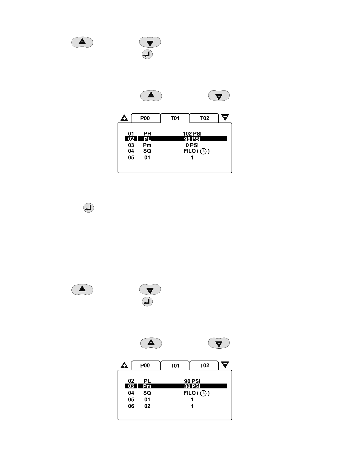
i. If PL is set for 98 PSI and TO is set for 3.0 PSI, then the lowest value for the High Pressure setpoint
would be 101 PSI.
5. Scroll up (+)
of for your air system. Press the ENTER
6. You should be returned to the T01 home screen and values just entered should appear next to the PH parameter.
LOW PRESSURE SETPOINT SETTINGS
1. From the T01 home screen scroll up (+)
(Low Pressure Setpoint).
2. The default setting for this parameter is 98 PSI. The 98 PSI indicates the Low Pressure Setpoint that used to load
the compressor when the Table is active.
3. Press the ENTER
4. The flashing cursor should be displayed highlighting the 98 PSI. The values for this parameter are:
• The highest value for the Low Pressure setpoint = PH “High Pressure” setpoint minus TO “Tolerance”.
i. If PH is set for 102 PSI and TO is set for 3.0 PSI, then the highest value for the Low Pressure
• The lowest value for the Low Pressure setpoint = Pm “Minimum Pressure Alarm” setpoint plus 2 times TO
“Tolerance”
i. If Pm is set for 80 PSI and TO is set for 3.0 PSI, then the lowest value for the Low Pressure setpoint
or scroll down (-) until the number is set to the value required to maintain control
button to confirm your selection.
or scroll down (-) to move the cursor to highlight 02- PL
Low Pressure Setpoint Setting
button to display the Low Pressure Setpoint setup screen.
setpoint would be 99 PSI.
would be 86 PSI...
5. Scroll up (+)
of for your air system. Press the ENTER
6. You should be returned to the T01 home screen and values just entered should appear next to the PL parameter.
MINIMUM PRESSURE ALARM SETTINGS
1. From the T01 home screen scroll up (+)
Pm (Minimum Pressure Alarm).
58
or scroll down (-) until the number is set to the value required to maintain control
button to confirm your selection.
or scroll down (-) to move the cursor to highlight 03-
Page 59

Minimum Pressure Alarm Setting
2. The default setting for this parameter is 80 PSI. The 80 PSI indicates the Minimum Low Pressure Setpoint that is
used to alarm if the pressure in the air system is low when the Table is active.
3. Press the ENTER
4. The flashing cursor should be displayed highlighting the 80 PSI. The values for this parameter are:
• The lowest Minimum Pressure Alarm setpoint = “The minimum range of the pressure transducer used.“
• The highest Minimum Pressure Alarm setpoint = “The value from the Table “PL – Low Pressure Setpoint”
value minus 6 PSI if in PSI, .4 BAR if in BAR, 41 kPA if in kPA.”
i. If PL in Table 1 (T01) is set for 100 PSI, then the highest Minimum Pressure setpoint would be 94
5. Scroll up (+)
of for your air system. Press the ENTER
6. You should be returned to the T01 home screen and values just entered should appear next to the Pm parameter.
SEQUENCE STRATEGY SETTINGS
1. From the S01 home screen scroll up (+)
(Sequence Strategy).
button to display the Minimum Low Pressure Setpoint setup screen.
PSI.
or scroll down (-) until the number is set to the value required to maintain control
button to confirm your selection.
or scroll down (-) to move the cursor to highlight 04- SQ
Sequence Strategy Setting
2. The default setting for this parameter is FILO. The FILO indicates the Sequence Control Strategy mode used when
the Table is active. Each sequence control strategy consists of two sub strategies. The ‘Rotation’ strategy defines
how the compressors are re-arranged, or re-ordered, in to a new sequence at each routine ‘Rotation’ event.
Rotation events are triggered by a cyclic interval time, a set time of day each day, or a set time of day once a week.
The compressor load ‘Control’ strategy defines how the compressors are utilized in response to variations in
system pressure
3. Press the ENTER
4. The flashing cursor should be displayed highlighting the FILO. The values for this parameter are:
• FILO – First In Last Out. The Rotation and Control functionality of the FILO mode is the first compressor
loaded is the last compressor to be unloaded
• FIFO – First In First Out. The Rotation and Control functionality of the FIFO mode is the first compressor
loaded is the first compressor to be unloaded
• VEC – Variable Energy Control. This uses the same Rotation and Control functionality of the FILO mode
with the additional control required for variable speed compressor installations
• EHR – Equal Hours Mode. The Rotation and Control functionality of the EHR mode is to equalize the Run
Hours on all compressors
5. Scroll up (+)
control of for your air system. Press the ENTER
6. You should be returned to the T01 home screen and values just entered should appear next to the SQ parameter
59
button to display the Sequence Strategy Setpoint setup screen.
or scroll down (-) until the control mode is set to the value required to maintain
button to confirm your selection.
Page 60

COMPRESSOR #1 PRIORITY SETTINGS
1. From the T01 home screen scroll up (+)
or scroll down (-) to move the cursor to highlight 05-
01 (Compressor Priority).
Compressor #1 Priority Setting
2. The default setting for this parameter is 1. The 1 indicates the Compressor Priority setting for compressor
number #1 Any compressor can be assigned any priority or remove it from Sequence Rotation and Control and any
number of compressors can have the same priority. By changing the priority setting, it can be used to modify the
‘Rotation’ sequence assignment. For example: The air system configuration is a single variable speed compressor
that should be always loaded first and act a trim compressor and 3 fixed speed compressors that should be
rotated on an equal basis. You would assign the variable speed compressor a Priority of 1 and the 3 fixed speed
compressors a Priority of 2. The variable speed compressor is always loaded first and the 3 fixed speed
compressors would load and rotate based on the Sequence and Rotation setup.
1 2 3 4
1222
#1
ABCD
#2
ACDB
#3
ADBC
#4
ABCD
Priority Example
3. Press the enter
button to display the Compressor Priority setup screen.
4. The flashing cursor should be displayed highlighting the 1. The values for this parameter are “1” for the highest
priority through “4” for the lowest priority. Value “ ” indicates inhibit from use while a table is active. The
compressor will be held unloaded and will not be utilized under any circumstances
5. Scroll up (+)
of for your air system. Press the ENTER
or scroll down (-) until the number is set to the value required to maintain control
button to confirm your selection.
6. You should be returned to the T01 home screen and values just entered should appear next to the 01 parameter.
COMPRESSOR #2 THROUGH 4 PRIORITY SETTINGS
1. Repeat Steps above for Compressor #2, #3, and #4 Priority settings. When complete, the ENTER
button to
confirm your selection. You should be returned to the T01 home screen
2. After you have completed adjusting the settings on the T01 screen, press the ESCAPE
button to return to the
page selection screen.
3. Repeat the T02 and T03 Tabs Screen if you will be using more than one Table in your application.
60
Page 61

4. After you have completed adjusting the settings on the other T0x screens, press the ESCAPE
to the page selection screen.
button to return
PRESSURE SCHEDULE CONFIGURATION P01 TAB SCREEN
1. After you have returned to the page selection screen, such as in figure 3, scroll up (+) or scroll down (-)
until the P01 page is highlighted.
P01 Tab Screen
2. Press ENTER
PRESSURE SCHEDULE SETTINGS
1. From the P01 home screen scroll up (+)
(Pressure Schedule).
to confirm your selection. The cursor should be flashing on line 01 01.
P01 Home Screen
or scroll down (-) to move the cursor to highlight 01- 01
Pressure Schedule Setpoints
2. The default setting for this parameter is -. --:-- - - - . The -. --:-- - - - indicates the Pressure Schedule is turned
off. The Pressure Schedule consists of 28 individual settings that instruct the X4I to change from one Table to
another, or put the system into Standby mode, dependant on time of day and day of the week. T
3. Press the ENTER
61
button to display the Pressure Schedule setup screen.
Page 62

4. The flashing cursor should be displayed highlighting the first dash after the #. This sets the Day of the Week for
the Pressure Schedule. The values for this parameter are:
• “1” for Monday to “7” for Sunday (a specific day of the week)
• “8” for every working day of the week (every day, Monday through Friday, excluding Saturday and Sunday)
• “9’” for every working day of the week (every day, Monday through Sunday)
• “–“ for disabling the Pressure Schedule
5. Scroll up (+)
air system. Press the ENTER
6. The flashing cursor should be displayed highlighting the Hours dash (Military Time). This sets the Hour for the
Pressure Schedule. The values for this parameter are “00” to “23”. The value “–“ indicates the Pressure Schedule is
disabled.
7. Scroll up (+)
air system. Press the ENTER
8. The flashing cursor should be displayed highlighting the Minutes dash. This sets the Minutes for the Pressure
Schedule. The values for this parameter are “0” to “59”. The value “–“ indicates the Pressure Schedule is disabled.
9. Scroll up (+)
air system. Press the ENTER
10. The flashing cursor should be displayed highlighting the Table / Standby mode selection. This instructs the
system to change from one ‘Table’ to another, or put the system in to ‘Standby’ mode for the Pressure Schedule.
The values for this parameter are:
• “T01”, “T02” or ‘T03” for the 3 different Tables
• “–
• “–––“represents the Pressure Schedule is disabled.
– “ for Standby Mode
or scroll down (-) until the value is set for the Pressure Schedule required for your
button to accept this parameter.
or scroll down (-) until the value is set for the Pressure Schedule required for your
button to accept this parameter.
or scroll down (-) until the value is set for the Pressure Schedule required for your
button to accept this parameter.
11. Scroll up (+)
air system. Press the ENTER
12. You should be returned to the P01 home screen and values just entered should appear next to the 01 parameter.
13. Repeat Steps 5.1.A 1 to 12 if additional Pressure Schedules are required. When complete, press the ENTER
button to confirm your selection.
14. You should be returned to the P01 home screen
15. After you have completed adjusting the settings on the P01 screen, press the ESCAPE
page selection screen.
PRE-FILL CONFIGURATION P02 TAB SCREEN
1. After you have returned to the page selection screen, such as in figure 3, scroll up (+)
until the P02 page is highlighted.
or scroll down (-) until the value is set for the Pressure Schedule required for your
button to accept this parameter.
button to return to the
or scroll down (-)
62
Page 63

P02 Tab Screen
2. Press ENTER
PRE-FILL FUNCTION SETTINGS
1. From the P02 home screen scroll up (+)
(pre-fill function).
to confirm your selection. The cursor should be flashing on line 01 PF.
Home Screen
or scroll down (-) to move the cursor to highlight 01- PF
Pre-fill Function Setpoint Screen
2. The default setting for this parameter is
function provides a controlled and energy efficient method of increasing pressure to normal operating levels at
system start. This feature avoids the inefficient potential for all available system compressors to start and load
before pressure reaches the normal operating level.
3. Press the ENTER
4. The flashing cursor should be displayed highlighting the
• “
• “
• “
63
” for the Pre-fill Function is Off
” for Pre-fill, Back-up Mode
i. Compressor(s) can be pre-selected as ‘Primary Pre-fill’ compressor(s) or ‘Backup Pre-fill’
! X
button to display the pre-fill function setpoint screen.
compressor(s). If a primary pre-fill compressor experiences a shutdown, or is stopped, it is
replaced by a pre-defined backup compressor and pre-fill continues.
” for Pre-fill, Standard Mode
. The indicates the pre-fill function is turned off. The pre-fill
. The values for this parameter are:
Page 64

i. If one or more of the pre-defined pre-fill compressors experiences a shutdown, or is stopped, the
pre-fill function is cancelled and normal operation begins.
5. Scroll up (+)
system. Press the ENTER
6. You should be returned to the P02 home screen and values just entered should appear next to the PF parameter.
PRE-FILL TIME SETTINGS
1. From the P02 home screen scroll up (+)
(Pre-fill Time).
2. The default setting for this parameter is – MIN . The – MIN indicates the Pre-fill Time is turned off. The Pre-fill
Time Setpoint (in minutes) determines the time the Pre-fill Function has to start and load the designated
Compressor/s to increase system pressure to normal operational levels
or scroll down (-) until the value is set for the Pre-fill Function required for your air
button to accept this parameter.
or scroll down (-) to move the cursor to highlight 02- PT
Pre-fill Time Setpoint Setting
3. Press the ENTER
4. The flashing cursor should be displayed highlighting the
• “–” for the Pre-fill Time is Off
• “1 to 120” for the number of minutes for the Pre-fill Time Setpoint
5. Scroll up (+)
system. Press the ENTER
6. You should be returned to the P02 home screen and values just entered should appear next to the PT parameter.
button to display the Pre-fill Time Setpoint screen.
. The values for this parameter are:
or scroll down (-) until the value is set for the Pre-fill Time required for your air
button to accept this parameter.
64
Page 65

PRE-FILL PRESSURE SETTINGS
1. From the P02 home screen scroll up (+)
(Pre-fill Pressure).
Pre-fill Pressure Setpoint Setting
2. The default setting for this parameter is 0 PS. The 0 PSI indicates the Pressure Setpoint used by the X4I to
determine if the Pre-fill Function is required at startup. If the system pressure is at, or above, this setting, the prefill function will be abandoned immediately and normal pressure control and sequence strategy will be
implemented. This setting is intended to inhibit ‘Pre-fill’ operation if pressure is already at an acceptable level at
system startup
3. Press the ENTER
4. The flashing cursor should be displayed highlighting the 0. The values for this parameter are:
• 0 to 232 (or the maximum scaling used by the X4I if a different Pressure Transducer range is used)” for
the PSI value for the Pre-fill Pressure
button to display the Pre-fill Pressure Setpoint screen.
or scroll down (-) to move the cursor to highlight 03- PP
5. Scroll up (+)
system. Press the ENTER
6. You should be returned to the P02 home screen and values just entered should appear next to the PP parameter.
PRE-FILL COMPRESSOR #1 SETTINGS
1. From the P02 home screen scroll up (+)
(Pressure Schedule).
2. The default setting for this parameter is
The Pre-fill Time Setpoint (in minutes) determines the time the Pre-fill Function has to start and load the
designated Compressor/s to increase system pressure to normal operational levels
or scroll down (-) until the value is set for the Pre-fill Pressure required for your air
button to accept this parameter.
or scroll down (-) to move the cursor to highlight 04- 01
Pre-fill Time Setting
. The indicates the Pre-fill Function for Compressor #1 s turned off.
3. Press the ENTER
4. The flashing cursor should be displayed highlighting the
• “
65
”” for this compressor will not be used by the Pre-fill Function
button to display the Pre-fill Time Setpoint screen.
. The values for this parameter are:
Page 66

• “
• “!” for this compressor will be used as an emergency Backup compressor by the Pre-fill Function
” for this compressor will be used as a primary compressor by the Pre-fill Function
5. Scroll up (+)
for your air system. Press the enter
6. You should be returned to the P02 home screen and values just entered should appear next to the 04 parameter.
PRE-FILL COMPRESSOR #2 THROUGH 4 SETTINGS
1. Repeat above steps for compressor #2, #3, and #4 Pre-fill Compressor settings. When complete, the ENTER
button to confirm your selection.
2. You should be returned to the P02 home screen
3. After you have been returned to the page selection screen, press the ESCAPE
screen.
or scroll down (-) until the value is set for the compressor Pre-fill Function required
button to accept this parameter.
button to return to the main
66
Page 67

DIAGNOSTICS D01 TAB SCREEN
1. After you have returned to the page selection screen, scroll up (+) or scroll down (-) until the
D01 page is highlighted.
D2 Tab Screen
2. Press ENTER
DIAGNOSTICS SETTINGS
1. From the D01 home screen scroll up (+)
D1 (Digital Input 1).
to confirm your selection. The cursor should be flashing on line 01 D1.
or scroll down (-) to move the cursor to highlight 01-
D01
20 Ao mA4.00
01 D1 0
D2
02
D3
03
D4
04
Diagnostic Setting Screen
2. The X4I is equipped with comprehensive diagnostic functions. Each input can be examined individually and each
output can be manually activated or manipulated individually.
0
1
2
67
Page 68

X4I CONTROLLER DIAGNOSTICS
D1 Digital Input 1
ON
D2 Digital Input 2
D3 Digital Input 3
D4 Digital Input 4
OFF
Pulsing
D5 Digital Input 5
D6 Digital Input 6
D7 Digital Input 7
D8 Digital Input 8
D9 Digital signal detected on A2
DA Digital signal detected on A3
_____________________________________________________________________________________________
R1 Relay Output 1
R2 Relay Output 2
R3 Relay Output 3
OFF
ON
R4 Relay Output 4
R5 Relay Output 5
R6 Relay Output 6
_____________________________________________________________________________________________
A1 Analog Input 1 bar <> mA
A2 Analog Input 2 v
A3 Analog Input 3 v
_____________________________________________________________________________________________
Ao Analog Output 0.0 to 20.0mA
DIGITAL INPUTS
OFF (open circuit)
ON (closed circuit)
Pulsing
The pulse signal from an “ir-PCB” is 0V to 24VDC at 50/60Hz. A typical DC voltage meter, or multimeter, will detect this as
12VDC +-4V.
RELAY OUTPUTS
Each relay output can be energized and de-energized manually by selecting the item. Use UP (plus) and DOWN (minus) to
adjust and ENTER.
68
Page 69

ANALOG INPUTS
The item will alternate between the detected value and the electrical measurement on the controller input terminals. An
independent measuring device can be used to check the displayed electrical measurement.
• A1: System Pressure, 4-20mA
• A2: Digital Input #9, voltage
• A3: Auxiliary Digital Input, voltage
Analog inputs 2 and 3 are equipped with ACM modules designed to conform to the standard specification for a
controller digital input. The inputs are utilized as digital inputs on this X4I.
ANALOG OUTPUT
The analog output can be manually adjusted. Use UP (plus) and DOWN (Minus) to adjust and ENTER. The output will return
to normal operational value upon menu exit.
After you have completed adjusting the settings on the D01 screen press the ESCAPE
selection screen.
After you have been returned to the page selection screen, press the ESCAPE
TOTAL UNIT RESET AND DEFAULT VALUES
If at any time there is a requirement to reset all the parameters and internal memory values to factory default, this can be
accomplished by using the following procedure.
1. Press the MENU
button. This will display the access code screen.
Access Code Screen
button to return to the main screen.
button to return to the page
2. Enter the access code “9750” but do not press the ENTER
flashing.
3. When the flashing cursor is highlighting the last “0”, press and hold the STOP
After 10 seconds, the controller will reset and re-initialize.
All parameters, values and options will be reset to default and the internal permanent memory will be cleared and
reset.
69
button when the last access code character “0” is
button for 10 seconds.
Page 70

The Default Parameters for all X4I settings are shown in the following lists.
TABLE #1
T01
PH High Pressure Setpoint
Default Setting is: 102 PSI
PL Low Pressure Setpoint
Default Setting is: 98 PSI
Pm Minimum Pressure Alarm
Default Setting is: 0 PSI
SQ Sequence Rotation Mode
Default Setting is: FILO
01 Compressor #1 Priority
Default Setting is: 1
02 Compressor #2 Priority
Default Setting is: 1
03 Compressor #3 Priority
Default Setting is: 1
04 Compressor #4 Priority
Default Setting is: 1
TABLE #3
T03
PH High Pressure Setpoint
Default Setting is: 102 PSI
PL Low Pressure Setpoint
Default Setting is: 98 PSI
Pm Minimum Pressure Alarm
Default Setting is: 0 PSI
SQ Sequence Rotation Mode
Default Setting is: FILO
01 Compressor #1 Priority
Default Setting is: 1
02 Compressor #2 Priority
Default Setting is: 1
03 Compressor #3 Priority
Default Setting is: 1
04 Compressor #4 Priority
Default Setting is: 1
TABLE #2
T02
PH High Pressure Setpoint
Default Setting is: 102 PSI
PL Low Pressure Setpoint
Default Setting is: 98 PSI
Pm Minimum Pressure Alarm
Default Setting is: 0 PSI
SQ Sequence Rotation Mode
Default Setting is: FILO
01 Compressor #1 Priority
Default Setting is: 1
02 Compressor #2 Priority
Default Setting is: 1
03 Compressor #3 Priority
Default Setting is: 1
04 Compressor #4 Priority
Default Setting is: 1
Pressure Schedule
P01
01 Schedule Setting #1
Default Setting is: -. - - : - - - - -
to
28 Schedule Setting #28
Default Setting is: -. - - : - - - - -
70
Page 71

Pre-fill
P02
PF Pre-fill Function
Default Setting is: X
PT Pre-fill Time
Default Setting is: - MIN
PP Pre-fill Pressure
Default Setting is: 0 PSI
01 Compressor #1
Default Setting is: X
02 Compressor #2
Default Setting is: X
03 Compressor #3
Default Setting is: X
04 Compressor #4
Default Setting is: X
User Configuration
S01
Ct Real Time Clock Set
Default Setting is: -. - - : - -
PS Pressure Schedule Enable
Default Setting is: X
AR Auto Restart Enable
Default Setting is:
RP Rotation Interval
Default Setting is: 1. 00:00
TS Default Table Select
Default Setting is: T01
BL Display Backlit Adjust
Default Setting is: 5
Configuration
S02
P> Pressure Units
Default Setting is: PSI
NC Number Of Compressors
Default Setting is: 4
PM Maximum Pressure Alarm
Default Setting is: 145 PSI
CF Stop Control Function
Default Setting is: X
TO Tolerance
Default Setting is: 3.0 PSI
DA Damping
Default Setting is: 1.0
PC Pressure Change Time
Default Setting is: 4 MIN
AI Auxiliary Input Function
Default Setting is: 05:SS NO
AO Auxiliary Output Function
Default Setting is: 07 ON NO
ER Error Log Reset
Default Setting is: X
Sensor Calibration
S03
1O Pressure Offset
Default Setting is: 0 PSI
1R Pressure Range
Default Setting is: 232 PSI
71
Page 72

Compressor Running Hours
C01
01 Compressor #1 Running Hours
Default Setting is: 0 HRS
02 Compressor #2 Running Hours
Default Setting is: 0 HRS
03 Compressor #3 Running Hours
Default Setting is: 0 HRS
04 Compressor #4 Running Hours
Default Setting is: 0 HRS
Compressor Configuration
C02
01 Compressor #1 Configuration
Default Setting is: IR-PCB
02 Compressor #2 Configuration
Default Setting is: IR-PCB
03 Compressor #3 Configuration
Default Setting is: IR-PCB
04 Compressor #4 Configuration
Default Setting is: IR-PCB
72
Page 73

PARTS LIST
Item Part No. Description
- 39265889 X4I
- 80443617 Manual, User CD
1 39265897 Unit, Controller
2 39265913 Unit, XPM-TAC24
3 39265905 PCB, Terminal
4 38036703 Gland, Set - Pg11
5 39265921 Module, ir-PCB
6 39265939 Sensor, Pressure
4-20mA, 232psi (16bar)
20mm
IEC
Qty. Part No. Description
10 39265962 IEC Fuse T1.0A
10 39265970 IEC Fuse T1.6A
10 39265988 IEC Fuse T3.15A
5mm
2
3
1
4
5
i-PCB
6
73
Page 74

TECHNICAL DATA
Dimensions 9.45” x 11.45” x 6.0”
241mm x 291mm x 152mm
Weight 14 lb (6.4 kg)
Mounting Wall, 4 x mounting screws
Enclosure IP65, NEMA 4
Power Supply 50VA
230Vac +/- 10% (50 Hz)
115Vac +/- 10% (60 Hz)
Control Power 24Vdc
Temperature 32°F to 115°F (0°C to 46°C)
Humidity 0% to 95% RH
non-condensing
24mm
188mm
24mm
Mounting Dimensions:
238mm
236mm
8mm Ø
286mm
74
Page 75

DIAGRAMS
Wiring Diagram
C031
C032
C09
C010
T1-56-321-R6-CG
A
6
m
0
0
2
X
-
4
A-GND
Ao
9
0
X
8
0
X
5
2
8
#
4
5
8
M
4
P
S
X
R
1
5
8
4
i
t
l
u
M
#
5
8
7
4
0
S
X
R
1
0
X
1
1
L
N
NL
E
230Vac 10%
115Vac 10%
1
L
2
L
1
L
2
L
c
a
V
4
2
2
2
5
0
X
2
0
X
3
0
X
2
0
X
E
E
1
0
X
+VDC
Ai1
+VDC
Ai2
+VDC
Ai3
4
0
X
R5
R6
R1
R3
4
2
C
A
T
M
P
X
C+
R2
R4
X03
1
2
3
4
5
6
7
8
9
2
0
C
c
a
V
0
1
0Vac - earthed
8
2
0
C
2
C019
C020
C021
C022
C023
C024
C025
C026
C027
C013
C014
C015
C016
C017
C018
c
a
V
4
2
24Vac
C03
C04
C05
C06
C07
C08
C011
C012
C01/3
C01/4
0VDC
Terminal PCB
C03
C04
C05
C06
C07
C08
C09
C010
C011
C012
C013
C014
C015
C016
C017
C018
C019
C020
C021
C022
C023
C024
C025
C026
C027
C028
C029
C030
C033
C034
C031
C032
c
a
V
4
2
D
N
G
C01
6
3
5
3
4
4
3
SEQ
2
GND
1
Q
E
S
-
+
D
N
G
C034
24Vac
SEQ
R-SEQ
C06
C08
C07
C010
C09
C04
C03
C019
C024
10k
150k
150k
C012
10k
C023
C027
C018
10k
C022
C026
3
3
3
2
3
1
3
0
3
9
2
8
2
7
2
6
2
5
2
4
2
3
2
2
2
1
2
0
2
9
1
4
V
8
1
7
1
6
1
5
1
4
1
3
1
3
V
2
1
1
1
0
1
9
-
+
R-V1
4-20mA
R-V2
R-V3
C016
R-V4
10k
C021
C025
C015
8
7
2
V
6
5
4
3
2
8
0
X
7
0
X
6
0
X
5
0
X
4
0
X
3
0
X
2
0
X
1
0
X
1
1
V
75
Page 76

Connection Diagram
Terminal PCB
6
3
5
3
4
3
3
3
2
3
1
3
0
3
9
2
8
2
7
2
6
2
5
2
4
2
3
2
2
2
1
2
0
2
9
1
4
V
8
1
7
1
6
1
5
1
4
1
3
1
3
V
2
1
1
1
0
1
9
8
7
2
V
6
5
4
3
2
1
1
V
115V 'UL' @ 5A maximum.
8
0
X
Auxiliary Output #1
7
0
Auxiliary Input #1
X
330ft (100m) max
L1
6
L2
0
X
L1
L2
5
0
X
4
0
X
3
0
X
2
0
X
1
0
X
-
Ai1
+20VDC
Ready/Run
Di5
Alarm/Serv.
Ai2
-
GND
LOAD
R5
SEQ
R1
VFD
V4
+20VDC
Ready/Run
Di4
Alarm/Serv.
Di8
-
GND
LOAD
R4
SEQ
R1
VFD
V3
+20VDC
Ready/Run
Di3
Alarm/Serv.
Di7
-
GND
LOAD
R3
SEQ
R1
VFD
V2
+20VDC
Ready/Run
Di2
Alarm/Serv.
Di6
-
GND
LOAD
R2
SEQ
R1
VFD
V1
System
Pressure
Multi485
L1
L2
330ft (100m) max
+
6
5
4
B
4
C
3
P
330ft (100m) max
-
i
2
1
V
6
5
3
B
4
C
3
P
-
i
2
1
V
6
5
2
B
4
C
3
P
-
i
2
1
V
6
5
1
B
4
C
3
P
-
i
2
1
V
I-PCB 6-core
I-VFD 7-core
330ft (100m) max
I-PCB 6-core
I-VFD 7-core
330ft (100m) max
I-PCB 6-core
I-VFD 7-core
330ft (100m) max
I-PCB 6-core
I-VFD 7-core
-
+
4-20mA
V
V
V
V
76
Page 77

XPM-TAC24
Power Supply Module
6
6
4 x 4.5mm
3
9
8
8
12 mm
BLACK
ORANGE
WHITE
1
234
VOLTAGE SELECT
T1.0A
EENL
X01
230V
115V
FH1
10
1234
230V +-10%
115V +-10%
32
12 mm
IEC
5x20mm
141
FH5
BLUE
A
5
1
.
3
T
BROWN
RED
GREEN
A
A
6
6
.
.
1
1
T
T
X03
212
X02
VIOLET
X04
FH2FH3FH4
A
0
.
1
T
1234
147
T1 S1
24Vac/2
earthed
24Vac/1
isolated
LNE
77
Page 78

Commissioning Form
Customer
Installation/Site
Software
#1
#2
#3
#4
psi
kW
psi
kW
psi
kW
psi
kW
VA
VA
VA
VA
cfm
Hz
cfm
Hz
cfm
Hz
cfm
Hz
Contact
Phone
Ser No.
Customer Ref:
Internal Ref:
Commission Date
Commission Engineer
Comp #1 Manufacturer
Comp #1 Model/Type
Comp #1 Working Pressure psi/bar
Comp #1 Full Load Capacity cfm
Comp #2 Manufacturer
Comp #2 Model/Type
Comp #2 Working Pressure psi/bar
Comp #2 Full Load Capacity cfm
Comp #3 Manufacturer
Comp #3 Model/Type
Comp #3 Working Pressure psi/bar
Comp #3 Full Load Capacity cfm
Comp #4 Manufacturer
Comp #4 Model/Type
Comp #4 Working Pressure psi/bar
Comp #4 Full Load Capacity cfm
T01 PH High Pressure Set Point psi/bar
T01 PL Low pressure Set Point psi/bar
T01 Pm Minimum Pressure Alarm psi/bar
T01 SQ Sequence Rotation Mode
EHR FIFO TR VEC
T01 01 Comp #1 Priority
T01 02 Comp #2 Priority
T01 03 Comp #3 Priority
T01 04 Comp #4 Priority
T02 PH High Pressure Set Point psi/bar
T02 PL Low pressure Set Point psi/bar
T02 Pm Minimum Pressure Alarm psi/bar
T02 SQ Sequence Rotation Mode
EHR FIFO TR VEC
T02 01 Comp #1 Priority
T02 02 Comp #2 Priority
T02 03 Comp #3 Priority
T02 04 Comp #4 Priority
T03 PH High Pressure Set Point psi/bar
T03 PL Low pressure Set Point psi/bar
T03 Pm Minimum Pressure Alarm psi/bar
T03 SQ Sequence Rotation Mode
EHR FIFO TR VEC
T03 01 Comp #1 Priority
T03 02 Comp #2 Priority
T03 03 Comp #3 Priority
T03 04 Comp #4 Priority
78
Page 79

S01 Ct Real Time Clock Set
S01 PS Pressure Schedule Enable
S01 AR Auto Restart Enable
S01 RP Rotation Interval or Time
S01 TS Default Table
T01 T02 T03
S02 P> Pressure Units
S02 NC Number of Compressors
bar psi kPa
1 2 3 4
S02 PM Maximum Pressure Alarm psi/bar
S02 CF Stop Control Function
S02 TO Tolerance
S02 DA Damping
S02 PC Pressure Change Time min
S02 AI Auxiliary Input Function
S02 AO Auxiliary Output Function
S03 1O Pressure Offset
S03 1R Pressure Range
P02 PF Prefill Function
!>X
P02 PT Prefill Time sec
P02 PP Prefill Pressure psi/bar
P02 01 Compressor #1 Prefill Function
P02 02 Compressor #2 Prefill Function
P02 03 Compressor #3 Prefill Function
P02 04 Compressor #4 Prefill Function
!
!
!
!
C01 01 Compressor #1 Running Hours hrs
C01 02 Compressor #2 Running Hours hrs
C01 03 Compressor #3 Running Hours hrs
C01 04 Compressor #4 Running Hours hrs
C02 01 Compressor #1 Connection
I-PCB V-PCB I-485 V-485
C02 Compressor #1 Start Time sec
C02 Compressor #1 Stop Time sec
C02 02 Compressor #2 Connection
I-PCB V-PCB I-485 V-485
C02 Compressor #2 Start Time sec
C02 Compressor #2 Stop Time sec
C02 03 Compressor #3 Connection
I-PCB V-PCB I-485 V-485
C02 Compressor #3 Start Time sec
C02 Compressor #3 Stop Time sec
C02 04 Compressor #4 Connection
I-PCB V-PCB I-485 V-485
C02 Compressor #4 Start Time sec
C02 Compressor #4 Stop Time sec
79
 Loading...